KR100804815B1 - Touch screen using infrared camera resistant to disturbance light - Google Patents
Touch screen using infrared camera resistant to disturbance lightDownload PDFInfo
- Publication number
- KR100804815B1 KR100804815B1KR1020070091409AKR20070091409AKR100804815B1KR 100804815 B1KR100804815 B1KR 100804815B1KR 1020070091409 AKR1020070091409 AKR 1020070091409AKR 20070091409 AKR20070091409 AKR 20070091409AKR 100804815 B1KR100804815 B1KR 100804815B1
- Authority
- KR
- South Korea
- Prior art keywords
- infrared
- touch screen
- light emitting
- light
- infrared camera
- Prior art date
- Legal status (The legal status is an assumption and is not a legal conclusion. Google has not performed a legal analysis and makes no representation as to the accuracy of the status listed.)
- Expired - Fee Related
Links
Images


Classifications
- G—PHYSICS
- G06—COMPUTING OR CALCULATING; COUNTING
- G06F—ELECTRIC DIGITAL DATA PROCESSING
- G06F3/00—Input arrangements for transferring data to be processed into a form capable of being handled by the computer; Output arrangements for transferring data from processing unit to output unit, e.g. interface arrangements
- G06F3/01—Input arrangements or combined input and output arrangements for interaction between user and computer
- G06F3/03—Arrangements for converting the position or the displacement of a member into a coded form
- G06F3/041—Digitisers, e.g. for touch screens or touch pads, characterised by the transducing means
- G06F3/042—Digitisers, e.g. for touch screens or touch pads, characterised by the transducing means by opto-electronic means
- G06F3/0421—Digitisers, e.g. for touch screens or touch pads, characterised by the transducing means by opto-electronic means by interrupting or reflecting a light beam, e.g. optical touch-screen
Landscapes
- Engineering & Computer Science (AREA)
- General Engineering & Computer Science (AREA)
- Theoretical Computer Science (AREA)
- Human Computer Interaction (AREA)
- Physics & Mathematics (AREA)
- General Physics & Mathematics (AREA)
- Position Input By Displaying (AREA)
Abstract
Translated fromKoreanDescription
Translated fromKorean본 발명은 적외선 카메라를 이용한 터치스크린에 관한 것으로, 상세하게는 다수의 적외선 발광소자를 구비한 적외선방사대와 적외선 카메라를 구비하여 터치스크린에서의 외란광에 의한 오작동이 방지되는 외란광에 강한 적외선 카메라를 이용한 터치스크린에 관한 것이다. The present invention relates to a touch screen using an infrared camera, and more particularly, to an infrared radiator having a plurality of infrared light emitting elements and an infrared camera, which is resistant to disturbance light caused by disturbance light on the touch screen. It relates to a touch screen using a camera.
일반적으로 터치스크린(Touch Screen)은 각종 디스플레이를 이용하는 정보통신기기와 사용자간의 인터페이스(24)를 구성하는 여러 방식중의 하나로서, 사용자가 손이나 펜으로 화면을 직접 접촉함으로 기기와 인터페이스 할 수 있는 입력장치이다.In general, the touch screen (Touch Screen) is one of a number of ways to configure the
이와 같은 터치스크린은 디스플레이에 표시되어 있는 버튼을 손가락으로 접촉하는 것만으로 컴퓨터를 대화적, 직감적으로 조작함으로 남녀노소 누구나 쉽게 사용할 수 있는 입력장치이기 때문에 현재 PDA, LCD, CRT, 은행이나 관공서, 각종 의료장비, 관광 및 주요기관의 안내, 교통안내 등 많은 분야에서 적용되고 있다.Such a touch screen is an input device that can be easily used by all ages and genders by manipulating the computer interactively and intuitively just by touching the buttons on the display with a finger. Currently, PDAs, LCDs, CRTs, banks, government offices, It is applied in many fields such as medical equipment, tourism and guidance of major institutions, and transportation guidance.
터치스크린을 구성하는 방식중에 대표적인 방식 중 하나인, 저항막 방식은 유리와 얇은 필름사이에 화학약품이 도포되어 있는 X축과 Y축의 측면에 얇은 금속판이 붙여진 구조로 이루어진다. 이러한 형태의 패널에 전원을 공급하면 일정량의 저항이 형성되고, 어느 한 부위에 손이나 기타 물체가 닿으면 화학약품이 반응하여 저항이 순간적으로 변화하게 되어, 측면의 금속판에서는 저항의 변화로부터 물체가 접촉한 위치좌표를 찾는다.One of the typical methods of constituting the touch screen, the resistive film method consists of a structure in which a thin metal plate is attached to the sides of the X and Y axes where chemicals are applied between the glass and the thin film. When power is supplied to this type of panel, a certain amount of resistance is formed, and when a hand or other object touches any part, chemical reacts and the resistance changes instantaneously. Find the position coordinate that you touched.
그러나 이와 같은 종래의 터치스크린의 저항막 방식은 큰 화상면에 적용하기 어렵고, 저항막이 쉽게 손상되기 때문에 일정한 위치를 계속적으로 사용하는 화상면에 적용할 수 없는 문제점이 있다.However, such a resistive film method of the conventional touch screen is difficult to apply to a large image surface, and since the resist film is easily damaged, there is a problem that it cannot be applied to an image surface that uses a constant position continuously.
또한 종래의 터치스크린을 구성하는 방식중에는 가시광 또는 적외선을 이용하여 터치스크린내의 좌표를 인식하는 방식이 적용되어 왔다. 이중 종래의 적외선을 이용한 터치스크린 방식으로는 적외선 송수신소자를 터치스크린의 외주면 전체에 각각 배열하게 되므로서 배치되는 적외선 송수신소자의 숫자가 많아지기 때문에 제조원가가 높아지는 문제점을 갖고 있으며, 특히 상기 터치스크린이 급작스럽게 강한 빛에 노출되거나 하는 등 외부환경에 크게 영향을 받는 경우에는 외란광에 직접적인 영향을 받게 되어 적외선 수신소자의 수신부의 최대검출값이 비정상적으로 높아지게 되고, 이에 따라 사용자의 터치가 없는 경우에도 적외선 수신부의 검출값이 상기 비정상적으로 높아진 최대검출값에 비하여 현저하게 낮아지게 인식되므로 물체가 존재하는 것으로 인식하게 되는 등 외란광에 매우 취약한 문제점을 갖고 있다.In addition, among the methods of configuring a conventional touch screen, a method of recognizing coordinates in the touch screen using visible light or infrared light has been applied. In the conventional touch screen method using infrared rays, the infrared transceiver elements are arranged on the entire outer circumferential surface of the touch screen, so that the number of infrared transceiver elements is increased, thus increasing the manufacturing cost. In the case of being greatly affected by the external environment such as sudden exposure to strong light, it is directly affected by the disturbance light, and thus the maximum detection value of the receiver of the infrared receiver is abnormally increased. Since the detection value of the infrared receiver is recognized to be significantly lower than the abnormally high maximum detection value, the detection value of the infrared receiver is very vulnerable to disturbance light.
본 발명은 상기와 같은 종래의 문제점을 해결하고자 안출된 것으로, 본 발명은 자연광이나 인공조명등에 의한 외란광을 차단하고 적외선만을 선택적으로 감지할 수 있는 밴드패스필터링기능을 갖는 적외선 카메라를 구비하여 외란광에 의한 오류가 방지될 수 있는 외란광에 강한 적외선 카메라를 이용한 터치스크린을 제공하는 것을 목적으로 한다.The present invention has been made to solve the above conventional problems, the present invention is disturbed by the infrared camera having a band pass filtering function that can block the disturbance light by natural light or artificial light, and selectively detect only infrared light An object of the present invention is to provide a touch screen using an infrared camera resistant to disturbance light, which can prevent errors caused by light.
또한 본 발명은 터치스크린에 적용되는 감지수단의 숫자를 줄이고, 큰화상면에도 적용가능한 저가의 비용으로 고효율의 기능이 구현되는 적외선 카메라를 이용한 터치스크린을 제공하는 것을 목적으로 한다.In addition, an object of the present invention is to reduce the number of sensing means applied to the touch screen, and to provide a touch screen using an infrared camera that is implemented at a high efficiency at a low cost that can be applied to a large image screen.
본 발명은 상기와 같은 목적을 달성하기 위하여 하기와 같은 실시예를 포함한다.The present invention includes the following examples in order to achieve the above object.
본 발명의 제1실시예는, 영상이 출력되는 화면부가 포함된 본체와; 다수개의 적외선 발광소자를 포함하여 상기 화면부를 중심으로 가로와 세로방향으로 각각 배열되는 적외선방사대와; 상기 적외선 발광소자에서 발광된 적외선을 수광하여 상기 적외선 발광소자의 수신유무에 따라 상기 화면부에 접촉된 물체의 위치를 감지하는 적외선 카메라를 포함한다.A first embodiment of the present invention includes a main body including a screen unit for outputting an image; An infrared radiator including a plurality of infrared light emitting elements and arranged in a horizontal direction and a vertical direction with respect to the screen unit; And an infrared camera which receives infrared light emitted from the infrared light emitting device and detects a position of an object in contact with the screen unit according to whether the infrared light emitting device is received.
본 발명의 제2실시예는, 제1실시예에 있어서, 상기 적외선 카메라는 상기 적외선 발광소자가 배열되지 않는 상기 화면부의 일측에서 상호 교차되는 지향각을 갖도록 적어도 두 개가 설치된다.In the second embodiment of the present invention, in the first embodiment, at least two infrared cameras are provided to have directing angles intersecting with each other on one side of the screen unit in which the infrared light emitting devices are not arranged.
본 발명의 제3실시예는, 제2실시예에 있어서, 상기 적외선 카메라는 다수개의 적외선 수신셀이 포함되는 적외선 감지수단과; 상기 터치스크린의 전면에서 발생된 적외선을 수광하기 화각을 갖는 렌즈와; 상기 렌즈를 투과한 광의 파장대역을 필터링하여 적외선만을 투과시키는 밴드패스필터와; 상기 밴드패스필터에서 필터링된 적외선이 수신되는 적외선 감지수단과; 상기 적외선 감지수단으로부터 물체의 접촉이 감지되면, 이를 본체에 출력하는 인터페이스를 포함한다.According to a third embodiment of the present invention, in the second embodiment, the infrared camera comprises: infrared sensing means including a plurality of infrared reception cells; A lens having an angle of view for receiving infrared rays generated in front of the touch screen; A band pass filter for filtering the wavelength band of the light transmitted through the lens and transmitting only infrared rays; Infrared detecting means for receiving infrared light filtered by the band pass filter; When the contact of the object is detected from the infrared sensing means, it comprises an interface for outputting it to the main body.
본 발명의 제4실시예는, 제3실시예에 있어서, 상기 적외선 감지수단은 CCD 또는 CMOS 이미지센서가 포함된다.In a fourth embodiment of the present invention, in the third embodiment, the infrared sensing means includes a CCD or a CMOS image sensor.
본 발명의 제5실시예는, 제3실시예에 있어서, 상기 적외선 감지수단은 각각 상기 터치스크린의 전면에서 적어도 90도 이상의 지향각을 갖도록 설치되어 해당 지향각내에 설치된 상기 적외선 발광소자에서 발광된 적외선을 수신한다.In a fifth embodiment of the present invention, in the third embodiment, the infrared detecting means are installed to have a directing angle of at least 90 degrees or more at the front of the touch screen, respectively, to emit light from the infrared light emitting element installed within the corresponding directing angle. Receive infrared light.
본 발명의 제6실시예는, 제5실시예에 있어서, 상기 적외선 감지수단은 다수개의 적외선 수신셀을 포함하고 있으며, 각각의 셀은 서로 다른 지향각을 갖고 설치되어 상기 적외선방사대의 적외선 발광소자로부터 발광된 적외선을 수광하는 것을 특징으로 한다.In the sixth embodiment of the present invention, in the fifth embodiment, the infrared sensing means includes a plurality of infrared receiving cells, each cell having a different directing angle, so that the infrared light emitting device of the infrared radiation band And receiving infrared rays emitted from the light.
본 발명의 제7실시예는, 제6실시예에 있어서, 상기 적외선방사대는 상기 적외선 발광소자가 지향되는 전면에 적외선을 확산시키는 확산수단을 더 포함하는 것을 특징으로 한다.According to a seventh embodiment of the present invention, in the sixth embodiment, the infrared radiation zone further includes diffusing means for diffusing infrared rays to the entire surface to which the infrared light emitting element is directed.
본 발명은 외란광을 차단하고 적외선을 차단하는 밴드패스필터가 포함된 적외선 카메라를 구비함에 따라 외란광에 의한 오작동이 없으므로 제품의 신뢰도 및 성능이 대폭 개선되는 효과가 있다.According to the present invention, since the infrared camera includes a band pass filter that blocks disturbance light and blocks infrared light, there is no malfunction due to disturbance light, thereby greatly improving the reliability and performance of the product.
또한 본 발명은 적외선 카메라와 적외선 발광소자를 구비함에 따라 종래에 비하여 감지센서의 숫자가 대폭 감소됨에 따라 제조비용이 낮아지는 효과가 있다.In addition, the present invention has an effect that the manufacturing cost is lowered as the number of the sensor is significantly reduced compared to the prior art by having an infrared camera and an infrared light emitting element.
이하에서는 본 발명에 따른 적외선 카메라를 이용한 터치스크린의 바람직한 실시예를 첨부된 도면을 참조하여 상세히 설명한다.Hereinafter, a preferred embodiment of a touch screen using an infrared camera according to the present invention will be described in detail with reference to the accompanying drawings.
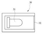
도 1은 본 발명에 따른 적외선 카메라를 이용한 터치스크린을 나타낸 평면도이다.1 is a plan view showing a touch screen using an infrared camera according to the present invention.
도 1을 참조하면, 본 발명에 따른 적외선 카메라(20)를 이용한 터치스크린은 영상이 출력되는 화면부(11)를 포함하는 본체(10)와, 상기 화면부(11)를 중심으로 X축과 Y축으로 배열되되, 다수개의 구획되어 각각이 구획공간에 적외선을 발광하는 적외선 발광소자(31)가 안착되는 적외선방사대(30)와, 상기 적외선 발광소자(31)에서 발광된 적외선의 차단유무를 통해 상기 화면부(11)의 접촉물체의 유무 및 그 위치를 감지하는 적외선 카메라(20)를 포함한다.Referring to FIG. 1, the touch screen using the
여기서 상기 적외선방사대(30)는, 도 1에 도시된 바를 예를 들자면, 상단 모서리를 제외한 X축과 Y축방향의 모서리에 세로방향과 가로방향으로 설치되며, 상기 적외선방사대(30)에 각각 안착된 적외선 발광소자(31)는 상기 화면부(11)를 지향하여 설치된다.Here, the
상기 적외선 카메라(20)는 상기 적외선방사대(30)가 설치되지 않은 상기 화면부(11)의 상단에서 좌측과 우측에 각각 하나씩 설치되며, 각각의 적외선 카메라(20)는 상호 교차되는 지향각을 갖고 상기 화면부(11)의 전면을 촬영한다.The
도 2는 본 발명에 따른 적외선 카메라를 이용한 터치스크린에서 적외선 카메라를 나타낸 블럭도이다.2 is a block diagram illustrating an infrared camera in a touch screen using an infrared camera according to the present invention.
도 2를 참조하면, 상기 적외선 카메라(20)는 적어도 90도 이상의 화각을 갖는 렌즈(21)와, 850~940nm의 파장대역을 갖는 적외광만을 투과시키고 그외 파장대역은 차단하는 밴드패스필터(22)와, 다수개의 수신셀(예를들면 512개의 수신셀)을 갖고 각각의 수신셀은 서로 다른 방향을 지향하여 각 적외선 발광소자(31)에서 발광된 적외광을 수광하는 적외선 감지수단(23)과, 상기 적외선 감지수단(23)의 광신호를 전기적신호로 변환시켜 제어장치에 출력하는 인터페이스(24)를 포함한다. 여기서 상기 제어부(도시되지 않음)는 본체(10)의 내부에 설치되며 상기 인터페이스(24)를 통해 출력된 상기 적외선 카메라(20)의 물체감지신호를 수신하여 해당 제어신호를 출력하게 된다.Referring to FIG. 2, the
상기 렌즈(21)는 상기 화면부(11)의 전면을 지향하여 상기 화면부(11)의 상단 모서리를 제외한 양측과 하단모서리에서 배열되는 적외선방사대(30)에서 발광되는 적외광을 수광하여 이를 투과시킨다. 이때 상기 적외선 카메라(20)는 상기 화면부(11)의 상단 모서리의 양측에서 서로 교차되는 지향각을 갖고 설치됨에 따라 상기 렌즈(21)의 화각 역시 적어도 90도 이상이 되어 일측 모서리에서 타측 모서리에 배열된 적외선방사대(30)를 지향하는 것이 바람직하다.The
상기 밴드패스필터(22)는 상기 렌즈(21)를 통해 투과되는 자연광이나 인공조명 및 상기 적외선방사대(30)에서 발광된 적외선이 입사되면, 이중에서 적외선 파장대역인 850~940nm 대역의 적외광만을 선택적으로 투과시킨다. 바람직하게는 상기 밴드패스필터(22)는 상기 적외선 발광소자(31)에서 발광된 적외선 파장대역(예를들면, 780~1100nm) 보다 더 좁은 파장 대역(850~940nm)만을 투과하도록 하여 외란광의 투과를 방지하도록 한다.The
상기 적외선 감지수단(23)은 CMOS나 CCD 이미지센서가 적용될 수 있으며, 각각의 이미지센서는 다수개의 적외선 수신셀, 예를들면 1~512번으로 고유색인번호가 정해진 적외선 수신셀이 설치되므로서 각각 서로 다른 방향을 지향하고 있어 상기 적외선 발광소자(31)에서 발광된 적외광을 수신한다. 상기 적외선 수신셀은 상기 터치스크린에 전원이 온되면, 상기 화면부(11)에 물체가 접촉되지 않은 상태에서는 상기 적외선 발광소자(31)의 광을 수신하게 된다. 그러나 상기 적외선 수신셀은 상기 화면부(11)에 물체가 접촉되면, 접촉된 물체에 의해 적외선이 막히므로 적외선이 수광되지 않게 되면 감지신호를 출력하게 된다. 이때 상기 적외선 수신셀 각각은 상술한 바와 같이 서로 다른 각도를 지향하게 되며, 상기 화면부(11)에 물체가 접촉되면 자신의 색인번호를 의미하는 코드와 함께 감지신호를 출력한다. 따라서 상기 제어부는 해당 수신셀의 색인번호를 통해 그 수신셀의 지향각을 판단하여 물체의 접촉위치를 인지하게 된다.The infrared detecting means 23 may be applied to a CMOS or CCD image sensor, each of the image sensor is a plurality of infrared receiving cells, for example, 1 to 512, the infrared receiving cell is assigned a unique index number They are directed in different directions to receive the infrared light emitted from the infrared
상기 인터페이스(24)는 상기 적외선 감지수단(23)에서 출력된 신호를 신호를 전기적인 신호 또는 아날로그 신호를 디지탈신호로 변환시켜 상기 제어부에서 인지 가능한신호로 출력한다. 여기서 상기 인터페이스(24)는 사용자의 응용에 따라 다양한 변형이 가능하다. 예를들면, 상기 적외선 감지수단(23)에서 광신호로써 물체의 접촉감지신호를 출력하면 이를 전기적인 신호로 변환시켜 출력하던가 또는 상기 적외선 감지수단(23)에서 아날로그 전기신호로 출력하면 이를 디지탈 신호로 변환시켜 상기 제어부에 출력한다.The
도 3은 본 발명에 따른 적외선 카메라를 이용한 터치스크린에서 적외선 방사대를 확대한 평면도, 도 4는 상기 적외선 방사대의 전면도, 도 5는 상기 적외선방사대의 확산수단을 나타낸 평면도이다.3 is an enlarged plan view of an infrared radiation band in a touch screen using an infrared camera according to the present invention, FIG. 4 is a front view of the infrared radiation band, and FIG. 5 is a plan view showing a diffusion means of the infrared radiation band.
도 3 내지 도 5를 참조하면, 적외선방사대는 도 3에 도시된 바와 같이 다수개의 구획공간이 형성되며, 각 구획공간내에는 상기 적외선 발광소자가 안착된다.3 to 5, the infrared radiation zone is formed with a plurality of compartments as shown in Figure 3, the infrared light emitting element is mounted in each compartment.
상기 적외선 발광소자(31)는 상기 화면부를 지향하여 설치되며, 각 적외선 발광소자(31)에서 발광된 적외선은 상기 화면부를 통해 상기 적외선 카메라(20)에서 수광된다. 또한 상기 적외선 발광소자(31)는 광이 발광되는 캡부분의 반대쪽에 전극이 위치되며, 각 전극은 인쇄회로기판(도시되지 않음)에 고정되거나 와이어를 통해 고정된다. 즉, 하나의 적외선 방사대(30)는 하나의 인쇄회로 기판 또는 여러개의 인쇄회로기판을 포함하며, 각각의 인쇄회로기판에는 상기 적외선 발광소자(31)가 적어도 하나 이상, 많게는 일측 모서리에 배열되는 상기 적외선방사대(30)의 모든 적외선 발광소자(31)가 하나의 인쇄회로 기판에 고정됨도 가능하다. 따라서 상기 제어부(도시되지 않음)의 제어신호에 따라 상기 인쇄회로기판을 통해 전원이 인가되면 상기 적외선 발광소자(31)는 발광한다.The infrared
아울러 상기 적외선방사대(30)는 상기 화면부(11)를 향하는 상기 적외선 발광소자(31)의 전면에서 확산수단(32)을 구비하고 있으며, 상기 확산수단(32)은 상기 적외선 발광소자(31)에서 발광된 적외선을 확산시키므로 상기 화면부(11)를 중심으로 하여 전체 영역에 상기 화면부(11)의 양측 모서리와 하단쪽에서 발광된 적외선이 입사된다. 따라서 종래와 같이 상기 화면부(11)의 상단과 하단, 양측모서리에 걸쳐 적외선 발광소자(31)를 배열할 필요가 없다.In addition, the
본 발명은 상기와 같은 구성을 포함하며, 그 작용설명은 하기의 도 6 내지 도 8을 참조하여 상세히 설명한다.The present invention includes the configuration as described above, the operation thereof will be described in detail with reference to Figures 6 to 8 below.
도 6은 본 발명에 따른 적외선 카메라를 이용한 터치스크린의 접촉 위치의 감지를 나타낸 평면도, 도 7은 본 발명에 따른 적외선 카메라를 이용한 터치스크린에서 물체의 접촉위치를 감지하는 적외선 감지수단의 실시예를 나타낸 개략도, 도 8은 본 발명에 따른 적외선 카메라를 이용한 터치스크린에서 상기 적외선 카메라에서 촬영된 접촉위치의 일예를 나타낸 도면이다.6 is a plan view showing the detection of the touch position of the touch screen using the infrared camera according to the present invention, Figure 7 is an embodiment of the infrared sensing means for detecting the contact position of the object in the touch screen using the infrared camera according to the present invention 8 is a diagram illustrating an example of a contact position captured by the infrared camera in a touch screen using an infrared camera according to the present invention.
도 6 내지 도 8을 참조하면, 본 발명에 따른 외란광에 강한 적외선 카메라(20)를 이용한 터치스크린은 사용자가 온하면, 상기 적외선 발광소자(31)가 적외선을 발광한다. 따라서 상기 적외선 카메라(20)에서 상기 렌즈(21)는 지향되는 각도 내의 적외선을 수광하게 되며, 상기 밴드패스필터(22)는 850~940nm의 적외선 대역만을 통과시키고 나머지는 대역대의 광을 차단한다. 그리고 상기 적외선 감지수단(23)은 상기 밴드패스필터(22)를 통과한 적외선을 자체 형성되는 다수개의 적외선 수신셀에서 수광한다.6 to 8, when the user turns on the touch screen using the
이후, 상기 화면부(11)에 사용자가 손가락 또는 터치스크린용 막대용 봉등을 이용하여 화면부(11)의 일부분(A)을 접촉하면, 해당 각도를 지향하여 발광된 적외선은 접촉된 물체에 의해 가로막히게 된다.Subsequently, when the user contacts a portion A of the
이때 상기 적외선 카메라(20)는 상기 적외선방사대(30)를 통해 방사되는 적외선을 기준으로 화면의 전면을 관측하다가 상술한 바와 같이 화면을 터치하는 물체가 화면에 들어올때 그 대상물에 의해 적외선이 수광되지 않는다. 이는 도 8에 도시된 바와 같다. 상기 적외선 카메라(20)는 도 8에 도시된 바와 같이 상기 화면부(11)가 수평의 띠모양으로 관측되며, 상기 화면부(11)를 터치하는 물체가 있으면, 해당 부분에서의 적외선이 수광되지 않으므로 상기 수평의 띠모양에서 가로막히지 않은 부분과 다른 색상을 갖는 것처럼 관측된다.At this time, the
좀 더 설명하자면, 상기 적외선 카메라(20)는 상기 화면부(11)가 적외선에 의해 발광되는 영역으로서 관측되기 때문에 흑 또는 백색으로서만 관측된다. 예를들면, 화면에 물체가 터치되기 이전에는 상기 화면부(11)가 흑색의 수평모양의 띠로서 관측되나 물체가 터치되면 그 부분만이 백색으로서 관측된다.More specifically, the
그러므로 상기 적외선 카메라(20)의 적외선 감지수단(23)은 다수의 적외선 수신셀에서 서로 다른 각도를 지향하면서 적외선을 수광하게 되므로서 상기 접촉부분을 지향하는 적외선 수신셀에서는 상술한 바와 같이 적외선을 수광하지 못하게 된다. 따라서 해당 적외선 수신셀은 감지신호를 상기 인터페이스(24)에 출력하며, 상기 제어부(도시되지 않음)는 인터페이스(24)를 통해 감지신호를 수신하여 그 물체의 위치를 판단한다.Therefore, the infrared detecting means 23 of the
즉, 상기 제어부(도시되지 않음)는 두 개의 적외선 카메라(20a, 20b)에서 물체의 감지신호를 출력한 적외선 수신셀을 확인하므로 해당 수신셀의 지향각을 인지하게 된다. 예를들면 화면부(11)의 좌측상단에 위치된 적외선 카메라(20a)의 적외선 수신셀중에서 311번 수신셀과, 우측상단에 위치된 적외선 카메라(20b)의 적외선 수신셀중에서 214번 수신셀에서 물체의접촉을 감지하게 되면, 상기 좌측의 311번 수신셀과 우측의 214번 수신셀의 지향각중에서 서로 만나는 점이 바로 물체의 접촉위치가 된다.That is, the controller (not shown) checks the infrared receiving cell which outputs the sensing signal of the object from the two
이와 같이 본 발명에 따른 외란광에 강한 적외선 카메라(20)를 이용한 터치스크린은 밴드패스필터(22)를 이용한 적외선 카메라(20)를 구비함에 따라 종래와 같이 화면부(11)를 중심으로 하여 적외선 발광소자(31)와 수광소자를 쌍으로서 배열할 필요가 없고, 외란광에 의한 오작동이 방지될 수 있다. 아울러, 본 발명은 적외선방사대(30)에 확산수단(32)을 구비할 수 있음에 따라 적외선 발광소자(31)의 숫자를 줄일 수 있다.As described above, the touch screen using the
도 1은 본 발명에 따른 외란광에 강한 적외선 카메라를 이용한 터치스크린을 나타낸 평면도,1 is a plan view showing a touch screen using an infrared camera resistant to disturbance light according to the present invention,
도 2는 본 발명에 따른 외란광에 강한 적외선 카메라를 이용한 터치스크린에서 적외선 카메라를 나타낸 블럭도,2 is a block diagram illustrating an infrared camera in a touch screen using an infrared camera resistant to disturbance light according to the present invention;
도 3은 본 발명에 따른 외란광에 강한 적외선 카메라를 이용한 터치스크린에서 적외선방사대를 확대한 평면도,3 is an enlarged plan view of an infrared radiation band in a touch screen using an infrared camera resistant to disturbance light according to the present invention;
도 4는 본 발명에 따른 외란광에 강한 적외선 카메라를 이용한 터치스크린에서 적외선방사대의 전면도,Figure 4 is a front view of the infrared radiation in the touch screen using an infrared camera resistant to disturbance light according to the present invention,
도 5는 본 발명에 따른 외란광에 강한 적외선 카메라를 이용한 터치스크린에서 적외선방사대의 확산수단을 나타낸 평면도,5 is a plan view showing the diffusion means of the infrared radiation in the touch screen using an infrared camera resistant to disturbance light according to the present invention,
도 6은 본 발명에 따른 외란광에 강한 적외선 카메라를 이용한 터치스크린의 접촉 위치의 감지를 나타낸 평면도,6 is a plan view showing the detection of the touch position of the touch screen using an infrared camera resistant to disturbance light according to the present invention,
도 7은 본 발명에 따른 외란광에 강한 적외선 카메라를 이용한 터치스크린에서 물체의 접촉위치를 감지하는 적외선 감지수단의 실시예를 나타낸 개략도,Figure 7 is a schematic diagram showing an embodiment of the infrared sensing means for detecting the contact position of the object in the touch screen using an infrared camera resistant to disturbance light according to the present invention,
도 8은 본 발명에 따른 외란광에 강한 적외선 카메라를 이용한 터치스크린에서 상기 적외선 카메라에서 촬영된 접촉위치의 일예를 나타낸 도면이다.8 is a view illustrating an example of a contact position photographed by the infrared camera in a touch screen using an infrared camera resistant to disturbance light according to the present invention.
*도면의 주요부분을 나타내는 부호의 설명** Description of Symbols Representing Major Parts of Drawings *
10: 본체 11 : 화면부10: main body 11: screen portion
20 : 적외선 카메라 21 : 렌즈20: infrared camera 21: lens
22 : 밴드패스필터 23 : 적외선 감지수단22: band pass filter 23: infrared detection means
24 : 인터페이스 30 : 적외선방사대24: interface 30: infrared radiation
31 : 적외선 발광소자 32 : 확산수단31: infrared light emitting device 32: diffusion means
Claims (7)
Translated fromKoreanPriority Applications (3)
| Application Number | Priority Date | Filing Date | Title |
|---|---|---|---|
| KR1020070091409AKR100804815B1 (en) | 2007-09-10 | 2007-09-10 | Touch screen using infrared camera resistant to disturbance light |
| PCT/KR2008/005119WO2009035227A2 (en) | 2007-09-10 | 2008-09-01 | Touch screen using infrared camera hardly affected by external disturbance light |
| US12/283,209US8139046B2 (en) | 2007-09-10 | 2008-09-10 | Touch screen using infrared camera hardly affected by external disturbance light |
Applications Claiming Priority (1)
| Application Number | Priority Date | Filing Date | Title |
|---|---|---|---|
| KR1020070091409AKR100804815B1 (en) | 2007-09-10 | 2007-09-10 | Touch screen using infrared camera resistant to disturbance light |
Publications (1)
| Publication Number | Publication Date |
|---|---|
| KR100804815B1true KR100804815B1 (en) | 2008-02-20 |
Family
ID=39382483
Family Applications (1)
| Application Number | Title | Priority Date | Filing Date |
|---|---|---|---|
| KR1020070091409AExpired - Fee RelatedKR100804815B1 (en) | 2007-09-10 | 2007-09-10 | Touch screen using infrared camera resistant to disturbance light |
Country Status (3)
| Country | Link |
|---|---|
| US (1) | US8139046B2 (en) |
| KR (1) | KR100804815B1 (en) |
| WO (1) | WO2009035227A2 (en) |
Cited By (13)
| Publication number | Priority date | Publication date | Assignee | Title |
|---|---|---|---|---|
| KR100919437B1 (en)* | 2009-05-26 | 2009-09-29 | 호감테크놀로지(주) | Illumination apparatus set of camera type touch panel |
| KR100968205B1 (en) | 2008-05-07 | 2010-07-06 | 전자부품연구원 | Infrared camera space touch sensing device, method and screen device |
| KR100974894B1 (en)* | 2009-12-22 | 2010-08-11 | 전자부품연구원 | 3d space touch apparatus using multi-infrared camera |
| KR101013757B1 (en)* | 2009-10-21 | 2011-02-14 | 주식회사위오스 | Tablet Fish Touch Screen |
| KR101022659B1 (en)* | 2008-06-12 | 2011-03-22 | 삼성에스디아이 주식회사 | Display device having a touch screen function, a method of detecting a touch position using the same, and a plasma display device |
| CN102096522A (en)* | 2010-11-05 | 2011-06-15 | 友达光电股份有限公司 | Light sensing control system |
| KR101205113B1 (en) | 2010-03-17 | 2012-11-26 | (주)더게이트테크놀러지스 | Optical Multi Touch System |
| US8493361B2 (en) | 2008-12-24 | 2013-07-23 | Lg Display Co., Ltd. | Touch type display device |
| KR101312805B1 (en) | 2012-03-19 | 2013-09-27 | (주)아이타키온 | Signal processing method of infrared type touch-screen system for multiple signal |
| KR101359731B1 (en) | 2012-03-29 | 2014-02-07 | (주)아이타키온 | System for recognizing touch-point using mirror |
| US8817001B2 (en) | 2010-11-01 | 2014-08-26 | Au Optronics Corp. | Optical sense-control system having light filters |
| KR101796857B1 (en) | 2016-04-25 | 2017-11-10 | 이준구 | Infrared touch screen device |
| WO2019054524A1 (en)* | 2017-09-12 | 2019-03-21 | 이준구 | Infrared touch screen device |
Families Citing this family (26)
| Publication number | Priority date | Publication date | Assignee | Title |
|---|---|---|---|---|
| KR100982331B1 (en)* | 2008-12-01 | 2010-09-15 | 삼성에스디아이 주식회사 | Plasma display device |
| TWM371272U (en)* | 2009-04-01 | 2009-12-21 | Pixart Imaging Inc | Optical touch control module |
| CN102597796B (en)* | 2009-06-16 | 2015-02-04 | 百安托国际有限公司 | Two-dimensional position sensing system and its sensor |
| US20110025646A1 (en)* | 2009-07-31 | 2011-02-03 | Wu xin-min | Extended infrared-sourced multi-touch screen |
| CN102053757B (en)* | 2009-11-05 | 2012-12-19 | 上海精研电子科技有限公司 | Infrared touch screen device and multipoint positioning method thereof |
| CN102129328A (en)* | 2010-01-16 | 2011-07-20 | 鸿富锦精密工业(深圳)有限公司 | Infrared touch screen |
| EP3129858A4 (en)* | 2013-11-22 | 2018-01-10 | FlatFrog Laboratories AB | A touch sensitive apparatus with improved spatial resolution |
| US11297284B2 (en)* | 2014-04-08 | 2022-04-05 | Udisense Inc. | Monitoring camera and mount |
| US10708550B2 (en)* | 2014-04-08 | 2020-07-07 | Udisense Inc. | Monitoring camera and mount |
| US9530080B2 (en)* | 2014-04-08 | 2016-12-27 | Joan And Irwin Jacobs Technion-Cornell Institute | Systems and methods for configuring baby monitor cameras to provide uniform data sets for analysis and to provide an advantageous view point of babies |
| DE102014206995A1 (en) | 2014-04-11 | 2015-10-15 | Osram Opto Semiconductors Gmbh | Optoelectronic semiconductor element, optoelectronic semiconductor component and method for producing a plurality of optoelectronic semiconductor elements |
| USD854074S1 (en) | 2016-05-10 | 2019-07-16 | Udisense Inc. | Wall-assisted floor-mount for a monitoring camera |
| CN110300950B (en) | 2017-02-06 | 2023-06-16 | 平蛙实验室股份公司 | Optical coupling in touch sensing systems |
| USD855684S1 (en) | 2017-08-06 | 2019-08-06 | Udisense Inc. | Wall mount for a monitoring camera |
| US11256371B2 (en) | 2017-09-01 | 2022-02-22 | Flatfrog Laboratories Ab | Optical component |
| CN107577377A (en)* | 2017-09-26 | 2018-01-12 | 哈尔滨工业大学 | The touch signal harvester of view-based access control model and infrared technique |
| EP3713487A4 (en) | 2017-11-22 | 2021-07-21 | UdiSense Inc. | BREATHING MONITOR |
| CN108449531B (en)* | 2018-03-26 | 2020-03-06 | 京东方科技集团股份有限公司 | Suspension touch camera module, electronic device and touch method |
| WO2020080992A1 (en) | 2018-10-20 | 2020-04-23 | Flatfrog Laboratories Ab | Frame for a touch-sensitive device and tool therefor |
| USD900431S1 (en) | 2019-01-28 | 2020-11-03 | Udisense Inc. | Swaddle blanket with decorative pattern |
| USD900429S1 (en) | 2019-01-28 | 2020-11-03 | Udisense Inc. | Swaddle band with decorative pattern |
| USD900428S1 (en) | 2019-01-28 | 2020-11-03 | Udisense Inc. | Swaddle band |
| USD900430S1 (en) | 2019-01-28 | 2020-11-03 | Udisense Inc. | Swaddle blanket |
| ES2991658T3 (en) | 2019-11-25 | 2024-12-04 | Flatfrog Lab Ab | A touch device |
| US12282653B2 (en) | 2020-02-08 | 2025-04-22 | Flatfrog Laboratories Ab | Touch apparatus with low latency interactions |
| US11893189B2 (en) | 2020-02-10 | 2024-02-06 | Flatfrog Laboratories Ab | Touch-sensing apparatus |
Citations (2)
| Publication number | Priority date | Publication date | Assignee | Title |
|---|---|---|---|---|
| JP2000132340A (en)* | 1998-06-09 | 2000-05-12 | Ricoh Co Ltd | Coordinate input/detecting device and electronic blackboard system |
| KR20070082958A (en)* | 2006-02-20 | 2007-08-23 | 호감테크놀로지(주) | Coordinate calculation method of touch point of infrared touch screen device and infrared touch screen |
Family Cites Families (3)
| Publication number | Priority date | Publication date | Assignee | Title |
|---|---|---|---|---|
| JP2000105671A (en)* | 1998-05-11 | 2000-04-11 | Ricoh Co Ltd | Coordinate input / detection device and electronic blackboard system |
| MXPA02005431A (en)* | 1999-12-02 | 2003-02-12 | Elo Touchsystems Inc | Apparatus and method to improve resolution of infrared touch systems. |
| KR20070024969A (en)* | 2005-08-31 | 2007-03-08 | (주)제니텀 엔터테인먼트 컴퓨팅 | Wall-type display device having an infrared sensing user interface and its operation method |
- 2007
- 2007-09-10KRKR1020070091409Apatent/KR100804815B1/ennot_activeExpired - Fee Related
- 2008
- 2008-09-01WOPCT/KR2008/005119patent/WO2009035227A2/enactiveApplication Filing
- 2008-09-10USUS12/283,209patent/US8139046B2/ennot_activeExpired - Fee Related
Patent Citations (2)
| Publication number | Priority date | Publication date | Assignee | Title |
|---|---|---|---|---|
| JP2000132340A (en)* | 1998-06-09 | 2000-05-12 | Ricoh Co Ltd | Coordinate input/detecting device and electronic blackboard system |
| KR20070082958A (en)* | 2006-02-20 | 2007-08-23 | 호감테크놀로지(주) | Coordinate calculation method of touch point of infrared touch screen device and infrared touch screen |
Cited By (18)
| Publication number | Priority date | Publication date | Assignee | Title |
|---|---|---|---|---|
| KR100968205B1 (en) | 2008-05-07 | 2010-07-06 | 전자부품연구원 | Infrared camera space touch sensing device, method and screen device |
| KR101022659B1 (en)* | 2008-06-12 | 2011-03-22 | 삼성에스디아이 주식회사 | Display device having a touch screen function, a method of detecting a touch position using the same, and a plasma display device |
| US8508488B2 (en) | 2008-06-12 | 2013-08-13 | Samsung Sdi Co., Ltd. | Display apparatus having touch screen function |
| US8493361B2 (en) | 2008-12-24 | 2013-07-23 | Lg Display Co., Ltd. | Touch type display device |
| KR100919437B1 (en)* | 2009-05-26 | 2009-09-29 | 호감테크놀로지(주) | Illumination apparatus set of camera type touch panel |
| KR101013757B1 (en)* | 2009-10-21 | 2011-02-14 | 주식회사위오스 | Tablet Fish Touch Screen |
| US8786576B2 (en) | 2009-12-22 | 2014-07-22 | Korea Electronics Technology Institute | Three-dimensional space touch apparatus using multiple infrared cameras |
| KR100974894B1 (en)* | 2009-12-22 | 2010-08-11 | 전자부품연구원 | 3d space touch apparatus using multi-infrared camera |
| KR101205113B1 (en) | 2010-03-17 | 2012-11-26 | (주)더게이트테크놀러지스 | Optical Multi Touch System |
| US8817001B2 (en) | 2010-11-01 | 2014-08-26 | Au Optronics Corp. | Optical sense-control system having light filters |
| CN102096522B (en)* | 2010-11-05 | 2013-04-17 | 友达光电股份有限公司 | Light sensing control system |
| CN102096522A (en)* | 2010-11-05 | 2011-06-15 | 友达光电股份有限公司 | Light sensing control system |
| KR101312805B1 (en) | 2012-03-19 | 2013-09-27 | (주)아이타키온 | Signal processing method of infrared type touch-screen system for multiple signal |
| KR101359731B1 (en) | 2012-03-29 | 2014-02-07 | (주)아이타키온 | System for recognizing touch-point using mirror |
| KR101796857B1 (en) | 2016-04-25 | 2017-11-10 | 이준구 | Infrared touch screen device |
| WO2019054524A1 (en)* | 2017-09-12 | 2019-03-21 | 이준구 | Infrared touch screen device |
| CN111065995A (en)* | 2017-09-12 | 2020-04-24 | 李准九 | Infrared touch panel device |
| CN111065995B (en)* | 2017-09-12 | 2023-07-21 | 李准九 | Infrared touch screen device |
Also Published As
| Publication number | Publication date |
|---|---|
| WO2009035227A3 (en) | 2009-06-04 |
| WO2009035227A2 (en) | 2009-03-19 |
| US8139046B2 (en) | 2012-03-20 |
| US20090066671A1 (en) | 2009-03-12 |
Similar Documents
| Publication | Publication Date | Title |
|---|---|---|
| KR100804815B1 (en) | Touch screen using infrared camera resistant to disturbance light | |
| US8659578B2 (en) | Optical sensing unit, display module and display device using the same | |
| US11182000B2 (en) | Smartphone | |
| EP3706036A1 (en) | Fingerprint recognition apparatus and electronic device | |
| KR100942293B1 (en) | Touch sensing method using light and touch panel device and system | |
| JP5389776B2 (en) | Reference setting method for optical touch input device and optical touch input device to which the method is applied | |
| EP3260956B1 (en) | Non-contact input device and method | |
| WO2010084640A1 (en) | Area sensor and liquid crystal display device with area sensor | |
| JP5296738B2 (en) | LCD with built-in touch screen | |
| CN112070018A (en) | Fingerprint identification device and electronic equipment | |
| JPH01195526A (en) | Touch panel device | |
| JP2011081766A (en) | Liquid crystal display device with built-in touch screen | |
| WO2012008168A1 (en) | Input device using touch panel and input method thereof | |
| US10180761B2 (en) | Touch-panel-equipped display device including side surface electrodes | |
| WO2005031554A1 (en) | Optical position detector | |
| KR101732957B1 (en) | Pen type and orientation recognition apparatus for optical touch screen | |
| KR20210103317A (en) | Fingerprint-touch combined sensor and electronic apparatus including the same | |
| CN111312793B (en) | Electronic equipment | |
| CN105022533A (en) | display module | |
| KR20130136313A (en) | Touch screen system using touch pen and touch recognition metod thereof | |
| KR102499513B1 (en) | Non-touch sensor module with improved recognition distance | |
| KR100955812B1 (en) | An interactive touch screen system for electric lecture | |
| KR20050077230A (en) | Pen-type position input device | |
| KR20200072670A (en) | Fingerprint sensing apparatus | |
| US20130170185A1 (en) | Display device with optical recognition of inputting instrument |
Legal Events
| Date | Code | Title | Description |
|---|---|---|---|
| A201 | Request for examination | ||
| PA0109 | Patent application | St.27 status event code:A-0-1-A10-A12-nap-PA0109 | |
| PA0201 | Request for examination | St.27 status event code:A-1-2-D10-D11-exm-PA0201 | |
| A302 | Request for accelerated examination | ||
| PA0302 | Request for accelerated examination | St.27 status event code:A-1-2-D10-D17-exm-PA0302 St.27 status event code:A-1-2-D10-D16-exm-PA0302 | |
| D13-X000 | Search requested | St.27 status event code:A-1-2-D10-D13-srh-X000 | |
| D14-X000 | Search report completed | St.27 status event code:A-1-2-D10-D14-srh-X000 | |
| E902 | Notification of reason for refusal | ||
| PE0902 | Notice of grounds for rejection | St.27 status event code:A-1-2-D10-D21-exm-PE0902 | |
| P11-X000 | Amendment of application requested | St.27 status event code:A-2-2-P10-P11-nap-X000 | |
| P13-X000 | Application amended | St.27 status event code:A-2-2-P10-P13-nap-X000 | |
| E701 | Decision to grant or registration of patent right | ||
| GRNT | Written decision to grant | ||
| PE0701 | Decision of registration | St.27 status event code:A-1-2-D10-D22-exm-PE0701 | |
| PR0701 | Registration of establishment | St.27 status event code:A-2-4-F10-F11-exm-PR0701 | |
| PR1002 | Payment of registration fee | St.27 status event code:A-2-2-U10-U11-oth-PR1002 Fee payment year number:1 | |
| PG1601 | Publication of registration | St.27 status event code:A-4-4-Q10-Q13-nap-PG1601 | |
| G170 | Re-publication after modification of scope of protection [patent] | ||
| PG1701 | Publication of correction | St.27 status event code:A-5-5-P10-P19-oth-PG1701 Patent document republication publication date:20080411 Republication note text:Request for Correction Notice (Document Request) Gazette number:1008048150000 Gazette reference publication date:20080220 | |
| PN2301 | Change of applicant | St.27 status event code:A-5-5-R10-R11-asn-PN2301 | |
| PN2301 | Change of applicant | St.27 status event code:A-5-5-R10-R14-asn-PN2301 | |
| S14-X000 | Exclusive voluntary license recorded | St.27 status event code:A-4-4-S10-S14-lic-X000 | |
| R18-X000 | Changes to party contact information recorded | St.27 status event code:A-5-5-R10-R18-oth-X000 | |
| S15-X000 | Recordation of exclusive voluntary license amended | St.27 status event code:A-4-4-S10-S15-lic-X000 | |
| FPAY | Annual fee payment | Payment date:20110201 Year of fee payment:4 | |
| PR1001 | Payment of annual fee | St.27 status event code:A-4-4-U10-U11-oth-PR1001 Fee payment year number:4 | |
| PN2301 | Change of applicant | St.27 status event code:A-5-5-R10-R11-asn-PN2301 | |
| PN2301 | Change of applicant | St.27 status event code:A-5-5-R10-R14-asn-PN2301 | |
| P14-X000 | Amendment of ip right document requested | St.27 status event code:A-5-5-P10-P14-nap-X000 | |
| P14-X000 | Amendment of ip right document requested | St.27 status event code:A-5-5-P10-P14-nap-X000 | |
| P16-X000 | Ip right document amended | St.27 status event code:A-5-5-P10-P16-nap-X000 | |
| Q16-X000 | A copy of ip right certificate issued | St.27 status event code:A-4-4-Q10-Q16-nap-X000 | |
| P15-X000 | Request for amendment of ip right document rejected | St.27 status event code:A-5-5-P10-P15-nap-X000 | |
| PN2301 | Change of applicant | St.27 status event code:A-5-5-R10-R11-asn-PN2301 | |
| PN2301 | Change of applicant | St.27 status event code:A-5-5-R10-R14-asn-PN2301 | |
| PN2301 | Change of applicant | St.27 status event code:A-5-5-R10-R13-asn-PN2301 St.27 status event code:A-5-5-R10-R11-asn-PN2301 | |
| PN2301 | Change of applicant | St.27 status event code:A-5-5-R10-R11-asn-PN2301 | |
| LAPS | Lapse due to unpaid annual fee | ||
| PC1903 | Unpaid annual fee | St.27 status event code:A-4-4-U10-U13-oth-PC1903 Not in force date:20120213 Payment event data comment text:Termination Category : DEFAULT_OF_REGISTRATION_FEE | |
| PN2301 | Change of applicant | St.27 status event code:A-5-5-R10-R14-asn-PN2301 | |
| PN2301 | Change of applicant | St.27 status event code:A-5-5-R10-R11-asn-PN2301 | |
| PN2301 | Change of applicant | St.27 status event code:A-5-5-R10-R14-asn-PN2301 | |
| P14-X000 | Amendment of ip right document requested | St.27 status event code:A-5-5-P10-P14-nap-X000 | |
| P16-X000 | Ip right document amended | St.27 status event code:A-5-5-P10-P16-nap-X000 | |
| Q16-X000 | A copy of ip right certificate issued | St.27 status event code:A-4-4-Q10-Q16-nap-X000 | |
| PC1903 | Unpaid annual fee | St.27 status event code:N-4-6-H10-H13-oth-PC1903 Ip right cessation event data comment text:Termination Category : DEFAULT_OF_REGISTRATION_FEE Not in force date:20120213 | |
| R18-X000 | Changes to party contact information recorded | St.27 status event code:A-5-5-R10-R18-oth-X000 | |
| R18-X000 | Changes to party contact information recorded | St.27 status event code:A-5-5-R10-R18-oth-X000 |