KR100804697B1 - Battery Management System and Its Driving Method - Google Patents
Battery Management System and Its Driving MethodDownload PDFInfo
- Publication number
- KR100804697B1 KR100804697B1KR1020060076148AKR20060076148AKR100804697B1KR 100804697 B1KR100804697 B1KR 100804697B1KR 1020060076148 AKR1020060076148 AKR 1020060076148AKR 20060076148 AKR20060076148 AKR 20060076148AKR 100804697 B1KR100804697 B1KR 100804697B1
- Authority
- KR
- South Korea
- Prior art keywords
- key
- soc
- ocv
- battery
- error range
- Prior art date
- Legal status (The legal status is an assumption and is not a legal conclusion. Google has not performed a legal analysis and makes no representation as to the accuracy of the status listed.)
- Expired - Fee Related
Links
Images


Classifications
- B—PERFORMING OPERATIONS; TRANSPORTING
- B60—VEHICLES IN GENERAL
- B60W—CONJOINT CONTROL OF VEHICLE SUB-UNITS OF DIFFERENT TYPE OR DIFFERENT FUNCTION; CONTROL SYSTEMS SPECIALLY ADAPTED FOR HYBRID VEHICLES; ROAD VEHICLE DRIVE CONTROL SYSTEMS FOR PURPOSES NOT RELATED TO THE CONTROL OF A PARTICULAR SUB-UNIT
- B60W20/00—Control systems specially adapted for hybrid vehicles
- B—PERFORMING OPERATIONS; TRANSPORTING
- B60—VEHICLES IN GENERAL
- B60L—PROPULSION OF ELECTRICALLY-PROPELLED VEHICLES; SUPPLYING ELECTRIC POWER FOR AUXILIARY EQUIPMENT OF ELECTRICALLY-PROPELLED VEHICLES; ELECTRODYNAMIC BRAKE SYSTEMS FOR VEHICLES IN GENERAL; MAGNETIC SUSPENSION OR LEVITATION FOR VEHICLES; MONITORING OPERATING VARIABLES OF ELECTRICALLY-PROPELLED VEHICLES; ELECTRIC SAFETY DEVICES FOR ELECTRICALLY-PROPELLED VEHICLES
- B60L50/00—Electric propulsion with power supplied within the vehicle
- B60L50/50—Electric propulsion with power supplied within the vehicle using propulsion power supplied by batteries or fuel cells
- B—PERFORMING OPERATIONS; TRANSPORTING
- B60—VEHICLES IN GENERAL
- B60K—ARRANGEMENT OR MOUNTING OF PROPULSION UNITS OR OF TRANSMISSIONS IN VEHICLES; ARRANGEMENT OR MOUNTING OF PLURAL DIVERSE PRIME-MOVERS IN VEHICLES; AUXILIARY DRIVES FOR VEHICLES; INSTRUMENTATION OR DASHBOARDS FOR VEHICLES; ARRANGEMENTS IN CONNECTION WITH COOLING, AIR INTAKE, GAS EXHAUST OR FUEL SUPPLY OF PROPULSION UNITS IN VEHICLES
- B60K6/00—Arrangement or mounting of plural diverse prime-movers for mutual or common propulsion, e.g. hybrid propulsion systems comprising electric motors and internal combustion engines
- B60K6/20—Arrangement or mounting of plural diverse prime-movers for mutual or common propulsion, e.g. hybrid propulsion systems comprising electric motors and internal combustion engines the prime-movers consisting of electric motors and internal combustion engines, e.g. HEVs
- B60K6/22—Arrangement or mounting of plural diverse prime-movers for mutual or common propulsion, e.g. hybrid propulsion systems comprising electric motors and internal combustion engines the prime-movers consisting of electric motors and internal combustion engines, e.g. HEVs characterised by apparatus, components or means specially adapted for HEVs
- B60K6/28—Arrangement or mounting of plural diverse prime-movers for mutual or common propulsion, e.g. hybrid propulsion systems comprising electric motors and internal combustion engines the prime-movers consisting of electric motors and internal combustion engines, e.g. HEVs characterised by apparatus, components or means specially adapted for HEVs characterised by the electric energy storing means, e.g. batteries or capacitors
- B—PERFORMING OPERATIONS; TRANSPORTING
- B60—VEHICLES IN GENERAL
- B60L—PROPULSION OF ELECTRICALLY-PROPELLED VEHICLES; SUPPLYING ELECTRIC POWER FOR AUXILIARY EQUIPMENT OF ELECTRICALLY-PROPELLED VEHICLES; ELECTRODYNAMIC BRAKE SYSTEMS FOR VEHICLES IN GENERAL; MAGNETIC SUSPENSION OR LEVITATION FOR VEHICLES; MONITORING OPERATING VARIABLES OF ELECTRICALLY-PROPELLED VEHICLES; ELECTRIC SAFETY DEVICES FOR ELECTRICALLY-PROPELLED VEHICLES
- B60L58/00—Methods or circuit arrangements for monitoring or controlling batteries or fuel cells, specially adapted for electric vehicles
- B60L58/10—Methods or circuit arrangements for monitoring or controlling batteries or fuel cells, specially adapted for electric vehicles for monitoring or controlling batteries
- B60L58/12—Methods or circuit arrangements for monitoring or controlling batteries or fuel cells, specially adapted for electric vehicles for monitoring or controlling batteries responding to state of charge [SoC]
- B60L58/15—Preventing overcharging
- B—PERFORMING OPERATIONS; TRANSPORTING
- B60—VEHICLES IN GENERAL
- B60L—PROPULSION OF ELECTRICALLY-PROPELLED VEHICLES; SUPPLYING ELECTRIC POWER FOR AUXILIARY EQUIPMENT OF ELECTRICALLY-PROPELLED VEHICLES; ELECTRODYNAMIC BRAKE SYSTEMS FOR VEHICLES IN GENERAL; MAGNETIC SUSPENSION OR LEVITATION FOR VEHICLES; MONITORING OPERATING VARIABLES OF ELECTRICALLY-PROPELLED VEHICLES; ELECTRIC SAFETY DEVICES FOR ELECTRICALLY-PROPELLED VEHICLES
- B60L58/00—Methods or circuit arrangements for monitoring or controlling batteries or fuel cells, specially adapted for electric vehicles
- B60L58/10—Methods or circuit arrangements for monitoring or controlling batteries or fuel cells, specially adapted for electric vehicles for monitoring or controlling batteries
- B60L58/24—Methods or circuit arrangements for monitoring or controlling batteries or fuel cells, specially adapted for electric vehicles for monitoring or controlling batteries for controlling the temperature of batteries
- B60L58/26—Methods or circuit arrangements for monitoring or controlling batteries or fuel cells, specially adapted for electric vehicles for monitoring or controlling batteries for controlling the temperature of batteries by cooling
- B—PERFORMING OPERATIONS; TRANSPORTING
- B60—VEHICLES IN GENERAL
- B60W—CONJOINT CONTROL OF VEHICLE SUB-UNITS OF DIFFERENT TYPE OR DIFFERENT FUNCTION; CONTROL SYSTEMS SPECIALLY ADAPTED FOR HYBRID VEHICLES; ROAD VEHICLE DRIVE CONTROL SYSTEMS FOR PURPOSES NOT RELATED TO THE CONTROL OF A PARTICULAR SUB-UNIT
- B60W10/00—Conjoint control of vehicle sub-units of different type or different function
- B60W10/04—Conjoint control of vehicle sub-units of different type or different function including control of propulsion units
- B60W10/06—Conjoint control of vehicle sub-units of different type or different function including control of propulsion units including control of combustion engines
- B—PERFORMING OPERATIONS; TRANSPORTING
- B60—VEHICLES IN GENERAL
- B60W—CONJOINT CONTROL OF VEHICLE SUB-UNITS OF DIFFERENT TYPE OR DIFFERENT FUNCTION; CONTROL SYSTEMS SPECIALLY ADAPTED FOR HYBRID VEHICLES; ROAD VEHICLE DRIVE CONTROL SYSTEMS FOR PURPOSES NOT RELATED TO THE CONTROL OF A PARTICULAR SUB-UNIT
- B60W10/00—Conjoint control of vehicle sub-units of different type or different function
- B60W10/04—Conjoint control of vehicle sub-units of different type or different function including control of propulsion units
- B60W10/08—Conjoint control of vehicle sub-units of different type or different function including control of propulsion units including control of electric propulsion units, e.g. motors or generators
- B—PERFORMING OPERATIONS; TRANSPORTING
- B60—VEHICLES IN GENERAL
- B60W—CONJOINT CONTROL OF VEHICLE SUB-UNITS OF DIFFERENT TYPE OR DIFFERENT FUNCTION; CONTROL SYSTEMS SPECIALLY ADAPTED FOR HYBRID VEHICLES; ROAD VEHICLE DRIVE CONTROL SYSTEMS FOR PURPOSES NOT RELATED TO THE CONTROL OF A PARTICULAR SUB-UNIT
- B60W10/00—Conjoint control of vehicle sub-units of different type or different function
- B60W10/24—Conjoint control of vehicle sub-units of different type or different function including control of energy storage means
- B60W10/26—Conjoint control of vehicle sub-units of different type or different function including control of energy storage means for electrical energy, e.g. batteries or capacitors
- B—PERFORMING OPERATIONS; TRANSPORTING
- B60—VEHICLES IN GENERAL
- B60K—ARRANGEMENT OR MOUNTING OF PROPULSION UNITS OR OF TRANSMISSIONS IN VEHICLES; ARRANGEMENT OR MOUNTING OF PLURAL DIVERSE PRIME-MOVERS IN VEHICLES; AUXILIARY DRIVES FOR VEHICLES; INSTRUMENTATION OR DASHBOARDS FOR VEHICLES; ARRANGEMENTS IN CONNECTION WITH COOLING, AIR INTAKE, GAS EXHAUST OR FUEL SUPPLY OF PROPULSION UNITS IN VEHICLES
- B60K1/00—Arrangement or mounting of electrical propulsion units
- B60K2001/003—Arrangement or mounting of electrical propulsion units with means for cooling the electrical propulsion units
- B60K2001/005—Arrangement or mounting of electrical propulsion units with means for cooling the electrical propulsion units the electric storage means
- B—PERFORMING OPERATIONS; TRANSPORTING
- B60—VEHICLES IN GENERAL
- B60W—CONJOINT CONTROL OF VEHICLE SUB-UNITS OF DIFFERENT TYPE OR DIFFERENT FUNCTION; CONTROL SYSTEMS SPECIALLY ADAPTED FOR HYBRID VEHICLES; ROAD VEHICLE DRIVE CONTROL SYSTEMS FOR PURPOSES NOT RELATED TO THE CONTROL OF A PARTICULAR SUB-UNIT
- B60W2510/00—Input parameters relating to a particular sub-units
- B60W2510/24—Energy storage means
- B60W2510/242—Energy storage means for electrical energy
- B60W2510/244—Charge state
- B—PERFORMING OPERATIONS; TRANSPORTING
- B60—VEHICLES IN GENERAL
- B60W—CONJOINT CONTROL OF VEHICLE SUB-UNITS OF DIFFERENT TYPE OR DIFFERENT FUNCTION; CONTROL SYSTEMS SPECIALLY ADAPTED FOR HYBRID VEHICLES; ROAD VEHICLE DRIVE CONTROL SYSTEMS FOR PURPOSES NOT RELATED TO THE CONTROL OF A PARTICULAR SUB-UNIT
- B60W2510/00—Input parameters relating to a particular sub-units
- B60W2510/24—Energy storage means
- B60W2510/242—Energy storage means for electrical energy
- B60W2510/246—Temperature
- Y—GENERAL TAGGING OF NEW TECHNOLOGICAL DEVELOPMENTS; GENERAL TAGGING OF CROSS-SECTIONAL TECHNOLOGIES SPANNING OVER SEVERAL SECTIONS OF THE IPC; TECHNICAL SUBJECTS COVERED BY FORMER USPC CROSS-REFERENCE ART COLLECTIONS [XRACs] AND DIGESTS
- Y02—TECHNOLOGIES OR APPLICATIONS FOR MITIGATION OR ADAPTATION AGAINST CLIMATE CHANGE
- Y02T—CLIMATE CHANGE MITIGATION TECHNOLOGIES RELATED TO TRANSPORTATION
- Y02T10/00—Road transport of goods or passengers
- Y02T10/60—Other road transportation technologies with climate change mitigation effect
- Y02T10/62—Hybrid vehicles
- Y—GENERAL TAGGING OF NEW TECHNOLOGICAL DEVELOPMENTS; GENERAL TAGGING OF CROSS-SECTIONAL TECHNOLOGIES SPANNING OVER SEVERAL SECTIONS OF THE IPC; TECHNICAL SUBJECTS COVERED BY FORMER USPC CROSS-REFERENCE ART COLLECTIONS [XRACs] AND DIGESTS
- Y02—TECHNOLOGIES OR APPLICATIONS FOR MITIGATION OR ADAPTATION AGAINST CLIMATE CHANGE
- Y02T—CLIMATE CHANGE MITIGATION TECHNOLOGIES RELATED TO TRANSPORTATION
- Y02T10/00—Road transport of goods or passengers
- Y02T10/60—Other road transportation technologies with climate change mitigation effect
- Y02T10/70—Energy storage systems for electromobility, e.g. batteries
Landscapes
- Engineering & Computer Science (AREA)
- Transportation (AREA)
- Mechanical Engineering (AREA)
- Chemical & Material Sciences (AREA)
- Combustion & Propulsion (AREA)
- Life Sciences & Earth Sciences (AREA)
- Sustainable Development (AREA)
- Sustainable Energy (AREA)
- Power Engineering (AREA)
- Automation & Control Theory (AREA)
- Secondary Cells (AREA)
- Electric Propulsion And Braking For Vehicles (AREA)
Abstract
Translated fromKoreanDescription
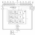
Translated fromKorean도 1은 본 발명의 실시예에 따른 배터리, BMS 및 BMS의 주변장치를 개략적으로 보여주는 도면이다.1 is a view schematically showing a battery, a BMS, and a peripheral device of a BMS according to an embodiment of the present invention.
도2 는 본 발명의 실시예에 따른 BMS(1)의 MCU(20)를 개략적으로 보여주는 도면이다.2 is a diagram schematically showing the
도3 은 본 발명의 실시예에 따라 MCU(20)에서 수행되는 초기 SOC의 산출과정을 개략적으로 보여주는 순서도이다.3 is a flowchart schematically illustrating a process of calculating an initial SOC performed by the
본 발명은 배터리 관리 시스템(Battery Management System)에 관한 것으로, 특히, 전기 에너지를 이용하는 자동차에 사용될 수 있는 배터리 관리 시스템 및 그의 구동방법에 관한 것이다.BACKGROUND OF THE
가솔린이나 중유를 주연료로 사용하는 내연 엔진을 이용하는 자동차는 대기오염 등 공해발생에 심각한 영향을 주고 있다. 따라서 최근에는 공해발생을 줄이기 위하여, 전기 자동차 또는 하이브리드(Hybrid) 자동차의 개발에 많은 노력을 기울 이고 있다.Automobiles using internal combustion engines that use gasoline or heavy oil as their main fuels have serious effects on pollution, such as air pollution. Therefore, in recent years, in order to reduce the occurrence of pollution, much efforts have been made in the development of electric vehicles or hybrid vehicles.
전기 자동차는 배터리(battery)에서 출력되는 전기에너지에 의해 동작하는 배터리 엔진을 이용하는 자동차이다. 이러한 전기 자동차는 충방전이 가능한 다수의 2차 전지(cell)가 하나의 팩(pack)으로 형성된 배터리를 주동력원으로 이용하기 때문에 배기가스가 전혀 없으며 소음이 아주 작은 장점이 있다.An electric vehicle is a vehicle using a battery engine operated by electric energy output from a battery. Such an electric vehicle uses no battery as a main power source because a plurality of secondary cells capable of charging and discharging are used as a pack has no exhaust gas and has a very small noise.
한편, 하이브리드 자동차라 함은 내연 엔진을 이용하는 자동차와 전기 자동차의 중간 단계의 자동차로서, 두 가지 이상의 동력원, 예컨대 내연 엔진 및 배터리 엔진을 사용하는 자동차이다. 현재에는, 내연 엔진과 수소와 산소를 연속적으로 공급하면서 화학반응을 일으켜 직접 전기 에너지를 얻는 연료 전지를 이용하거나, 배터리와 연료 전지를 이용하는 등 혼합된 형태의 하이브리드 자동차가 개발되고 있다.A hybrid vehicle, on the other hand, is an intermediate vehicle between an automobile using an internal combustion engine and an electric vehicle, and a vehicle using two or more power sources such as an internal combustion engine and a battery engine. At present, a hybrid vehicle of a hybrid type has been developed, such as using a fuel cell that directly generates an electric energy by chemical reaction while continuously supplying an internal combustion engine and hydrogen and oxygen, or uses a battery and a fuel cell.
이와 같이 배터리 엔진을 이용하는 자동차는 동력원 향상을 위해 2차 전지(CELL)의 수가 점차 증가되고 있으며, 연결된 다수의 셀을 효율적으로 관리 할 수 있는 셀밸런싱 제어방법이 배터리 관리 시스템(Battery Management System, 이하 BMS)에 필요하다As such, a vehicle using a battery engine is gradually increasing the number of secondary cells (CELL) to improve the power source, and a cell balancing control method for efficiently managing a plurality of connected cells is a battery management system (hereinafter referred to as a battery management system). BMS)
특히, 배터리의 충전상태(state of charge: 이하 'SOC'라함.)는 키온(KEY ON)시 개방 회로 전압(Open Circuit Voltage: 이하 'OCV'라함.)을 측정하고, SOC 및 온도에 대응하는 OCV에 관한 테이블 이용하여 초기 SOC를 추정한다.In particular, the state of charge (hereinafter referred to as 'SOC') of the battery measures the open circuit voltage (hereinafter referred to as 'OCV') when the key is ON and corresponds to the SOC and temperature. Estimates the initial SOC using a table of OCVs.
그러나 종래 초기 SOC 추정은 키오프 뒤 다시 키온이 될 때까지의 키오프시간과, 키온 시 측정된 온도 및 OCV와 키오프 시 측정된 온도 및SOC의 오차범위에 대응하는 OCV의 오차범위를 고려하지 않고 SOC 및 온도에 대응하는 OCV에 관한 테이블을 이용하여 초기 SOC를 추정하였기 때문에, 키온 시 정확한 초기 SOC를 추정하는데 문제점이 있다.However, the conventional initial SOC estimation does not take into account the keyoff time from keyoff to keyon and the error range of OCV corresponding to the temperature and OCV measured at keyon and the temperature and OCV measured at keyoff. Since the initial SOC was estimated using the table of the OCV corresponding to the SOC and the temperature, there is a problem in estimating the correct initial SOC at the time of key-on.
본 발명이 이루고자 하는 기술적 과제는 키오프 뒤 다시 키온이 될 때까지의 키오프시간과 키온 및 키오프 시 배터리의 상태를 고려하여 보다 정확하게 초기 SOC를 추정하는 배터리 관리 시스템 및 그 구동 방법을 제공하는 것이다.SUMMARY OF THE INVENTION The present invention provides a battery management system and a method of driving the same, which more accurately estimate an initial SOC in consideration of the key-off time from the key-off to the key-on and the state of the battery during key-on and key-off. will be.
본 발명의 한 특징에 따른 엔진 콘트롤 유닛(engine controller unit) 및 상기 엔진 콘트롤 유닛에 의해 제어되는 모터제너레이터를 포함하며, 복수의 전지 셀이 하나의 팩으로 구성되어 적어도 하나의 팩을 포함하는 배터리에 연결되는 하이브리드(Hybrid) 자동차의 배터리 관리 시스템에 있어서, 상기 배터리의 온도, 전류 및 키온 시 OCV(open circuit voltage)를 측정하는 센싱부, 및 상기 온도, 전류 및 키온 시 OCV를 전달받아, 배터리의 키오프 뒤 다시 키온이 될 때까지의 키오프시간과 키온 및 키오프 시 온도차를 산출하고, 키오프 시SOC의 오차범위에 대응하는 OCV의 오차범위를 산출하여 키온 시 상기 배터리의 초기 SOC를 추정하는 MCU를 포함한다. 그리고, 상기 MCU는 상기 키오프시간이 기준시간보다 짧으면, 상기 키오프 시 SOC를 상기 배터리의 초기 SOC로 추정한다. 이때, 상기 MCU는 상기 키오프시간이 기준시간보다 길면, 상기 배터리의 키온 및 키오프 시 온도와 키온 시 OCV를 전달받고, 상기 키오프 시 SOC의 오차범위에 대응하는 OCV의 오차범위를 산출하고, 상기 키온 시 OCV가 상기 키오프 시 SOC의 오차범위에 대응하는 OCV의 오차범위 사이의 전압이 아니면, SOC 및 온도에 대응하는 OCV에 관한 테이블을 이용하여 초기 SOC를 추정한다. 또한, 상기 MCU는 상기 키온 시 OCV가 상기 키오프 시SOC의 오차범위에 대응하는 OCV의 오차범위 사이의 전압이고, 상기 키온 및 키오프 시 측정된 온도차가 기준온도차이보다 작으면, 상기 키오프 시SOC를 상기 배터리의 초기 SOC로 추정한다. 그러나, 상기 MCU는 상기 키온 시 OCV가 상기 키오프 시 SOC의 오차범위에 대응하는 OCV의 오차범위 사이의 전압이고, 상기 키온 및 키오프 시 측정된 온도차가 상기 기준온도차이보다 크면, SOC 및 온도에 대응하는 OCV에 관한 테이블을 이용하여 초기 SOC를 추정한다. 이때, 상기 기준시간은 초기 SOC추정 시 상기 키오프시간과 비교되는 시간이며, 키온 시 상기 OCV가 안정화 상태에 도달될 때까지의 시간이다. 그리고, 상기 기준온도차이는 초기 SOC를 추정하기 위해 키온 및 키오프 시 온도차와 비교되는 온도이며, 키온 및 키오프 시 측정된 각각의 온도에 대응하여 결정되는 온도차이다.According to an aspect of the present invention, there is provided a battery including an engine controller unit and a motor generator controlled by the engine control unit, wherein a plurality of battery cells are configured as one pack and include at least one pack. In a battery management system of a hybrid vehicle to be connected, a sensing unit for measuring the temperature, current and open circuit voltage (OCV) of the battery and the OCV received at the temperature, current and keyon of the battery, Calculate the key-off time from key-off to key-on and the temperature difference at key-on and key-off, and calculate the error range of OCV corresponding to the error range of SOC at key-off to estimate the initial SOC of the battery at key-on It includes an MCU. If the keyoff time is shorter than the reference time, the MCU estimates the SOC as the initial SOC of the battery during the keyoff. In this case, when the key-off time is longer than the reference time, the MCU receives the key-on and key-off temperature of the battery and the OCV at the key-on, and calculates an error range of the OCV corresponding to the error range of the SOC at the key-off. When the OCV at the key-on is not a voltage between the error ranges of the OCV corresponding to the error range of the SOC at the key-off, the initial SOC is estimated using a table relating to the SOC and the OCV corresponding to the temperature. The MCU may be a voltage between the error range of the OCV corresponding to the error range of the SOC when the key-on OCV, and when the temperature difference measured at the key-on and key-off is less than a reference temperature difference, Assume SOC as the initial SOC of the battery. However, the MCU is a voltage between the error range of the OCV corresponding to the error range of the SOC when the key-on OCV, and when the temperature difference measured at the key-on and key-off is greater than the reference temperature difference, SOC and temperature The initial SOC is estimated using the table for the corresponding OCV. In this case, the reference time is a time compared with the key-off time at the time of initial SOC estimation, and is a time until the OCV reaches a stabilization state during key-on. The reference temperature difference is a temperature that is compared with a temperature difference at key-on and key-off to estimate an initial SOC, and is a temperature difference determined corresponding to each temperature measured at key-on and key-off.
본 발명의 다른 특징에 따른 엔진 콘트롤 유닛(engine controller unit) 및 상기 엔진 콘트롤 유닛에 의해 제어되는 모터제너레이터를 포함하며, 복수의 전지 셀이 하나의 팩으로 구성되어 적어도 하나의 팩을 포함하는 배터리에 연결되는 하이브리드(Hybrid) 자동차의 배터리 관리 시스템의 구동방법에 있어서,According to another aspect of the present invention, there is provided a battery including an engine controller unit and a motor generator controlled by the engine control unit, wherein a plurality of battery cells are configured as one pack and include at least one pack. In a method of driving a battery management system of a hybrid vehicle to be connected,
a) 상기 배터리의 키오프시간을 기준시간과 비교 하는 단계,a) comparing the key off time of the battery with a reference time,
b) 상기 키온 시 OCV가 상기 키오프 시 SOC의 오차범위에 대응하는 OCV의 오차범위 사이의 전압인지 비교하는 단계,b) comparing whether the OCV at the key-on is a voltage between the error ranges of the OCV corresponding to the error range of the SOC at the key-off;
c) 상기 키온 및 키오프 시 온도차를 상기 기준온도차이와 비교하는 단계, 및c) comparing the temperature difference during the key-on and key-off with the reference temperature difference, and
d) 상기 a), b) 및 c)비교결과에 대응하여, 초기 SOC를 추정하는 단계를 포함한다. 이때, 상기 d)단계에서 상기 a)비교결과, 상기 키오프시간이 상기 기준간보다 짧으면, 키오프 시 SOC를 상기 배터리의 초기 SOC로 추정한다. 그리고, 상기 d)단계에서 상기 a)비교결과, 상기 키오프시간이 상기 기준시간보다 길면, 키온 및 키오프 시 온도와 키온 시 OCV를 전달받고, 상기 키오프 시 SOC의 오차범위에 대응하는 OCV의 오차범위를 생성하는 단계를 포함한다. 또한, 상기 d)단계에서 상기 b)비교결과, 상기 키온 시 OCV가 상기 키오프 시 SOC의 오차범위에 대응하는 OCV의 오차범위 사이의 전압이 아니면, SOC 및 온도에 대응하는 OCV에 관한 테이블을 이용하여 초기 SOC를 추정하는 단계를 포함한다. 그리고, 상기 d)단계에서 상기 b) 및 c)비교결과, 상기 키온 시 OCV가 상기 키오프 시 SOC의 오차범위에 대응하는 OCV의 오차범위 사이의 전압이고, 상기 키온 및 키오프 시 측정된 온도차가 기준온도차이보다 작으면, 상기 키오프 시 SOC를 상기 배터리의 초기 SOC로 추정한다. 그러나, 상기 d)단계에서 상기 b) 및 c)비교결과, 상기 키온 시 OCV가 상기 키오프 시SOC의 오차범위에 대응하는 OCV의 오차범위 사이의 전압이고, 상기 키온 및 키오프 시 측정된 온도차가 상기 기준온도차이보다 크면, SOC 및 온도에 대응하는 OCV에 관한 테이블을 이용하여 초기 SOC를 추정한다. 그리고, 상기 a)단계의 기준시간은 키온 시 OCV가 안정화 상태에 도달될 때까지 걸리는 시간이다. 또한, 상기 c)단계의 기준온도차이는 키온 및 키오프 시 측정된 각각의 온도에 대응하여 결정되는 온도차이다.d) estimating an initial SOC, corresponding to the comparison results a), b) and c). In this case, if the keyoff time is shorter than the reference result in step d), the SOC is estimated as the initial SOC of the battery. When the keyoff time is longer than the reference time in step d), the keyon and the keyoff temperature and the OCV at the keyon are received, and the OCV corresponding to the error range of the SOC at the keyoff time. Generating an error range of. Further, in step d), if the comparison result of b) indicates that the OCV at the key-on is not a voltage between the error ranges of the OCV corresponding to the error range of the SOC at the key-off, a table relating to the OCV corresponding to the SOC and the temperature is provided. Estimating an initial SOC. And, in the step d) and b) and c) comparison result, the OCV at the key-on is the voltage between the error range of the OCV corresponding to the error range of the SOC at the key-off, the temperature difference measured at the key-on and key-off Is smaller than the reference temperature difference, the SOC at the keyoff is estimated as the initial SOC of the battery. However, as a result of comparing b) and c) in the step d), the temperature difference between the error range of the OCV corresponding to the error range of the SOC at the time of turning off the key when the OCV at the time of turning off the key is measured. If is greater than the reference temperature difference, the initial SOC is estimated using a table relating to the SOC and the OCV corresponding to the temperature. In addition, the reference time of step a) is a time taken until the OCV reaches a stabilization state during key-on. In addition, the reference temperature difference of step c) is a temperature difference determined corresponding to each temperature measured at the time of key-on and key-off.
아래에서는 첨부한 도면을 참고로 하여 본 발명의 실시예에 대하여 본 발명 이 속하는 기술 분야에서 통상의 지식을 가진 자가 용이하게 실시할 수 있도록 상세히 설명한다. 그러나 본 발명은 여러 가지 상이한 형태로 구현될 수 있으며 여기에서 설명하는 실시예에 한정되지 않는다. 도면에서 본 발명을 명확하게 설명하기 위해서 설명과 관계없는 부분은 생략하였다. 명세서 전체를 통하여 유사한 부분에 대해서는 동일한 도면 부호를 붙였다.Hereinafter, exemplary embodiments of the present invention will be described in detail with reference to the accompanying drawings so that those skilled in the art may easily implement the present invention. As those skilled in the art would realize, the described embodiments may be modified in various different ways, all without departing from the spirit or scope of the present invention. In the drawings, parts irrelevant to the description are omitted in order to clearly describe the present invention. Like parts are designated by like reference numerals throughout the specification.
명세서 전체에서, 어떤 부분이 다른 부분과 "연결"되어 있다고 할 때, 이는 "직접적으로 연결"되어 있는 경우뿐 아니라, 그 중간에 다른 소자를 사이에 두고 "전기적으로 연결"되어 있는 경우도 포함한다. 또한 어떤 부분이 어떤 구성요소를"포함"한다고 할 때, 이는 특별히 반대되는 기재가 없는 한 다른 구성요소를 제외하는 것이 아니라 다른 구성요소를 더 포함할 수 있는 것을 의미한다.Throughout the specification, when a part is "connected" to another part, this includes not only "directly connected" but also "electrically connected" with another element in between. . In addition, when a part is said to "include" a certain component, this means that it may further include other components, except to exclude other components unless specifically stated otherwise.
도 1은 본 발명의 실시예에 따른 배터리, BMS 및 BMS의 주변장치를 개략적으로 보여주는 도면이다.1 is a view schematically showing a battery, a BMS, and a peripheral device of a BMS according to an embodiment of the present invention.
도 1에 도시된 바와 같이, 자동차 시스템은, BMS(battery management system)(1), 배터리(2), 전류센서(3), 냉각팬(4), 퓨즈(5), 메인 스위치(6), ECU(engine controller unit, 7), 인버터(8) 및 모터제너레이터(9)를 포함한다.As shown in FIG. 1, the automotive system includes a battery management system (BMS) 1, a
먼저, 배터리(2)는 복수의 전지 셀이 서로 직렬로 연결된 복수의 서브팩(2a ~ 2h), 출력단자(2_OUT1), 출력단자(2_OUT2) 및 서브팩(2d)과 서브팩(2e) 사이에 마련되는 안전스위치(2_SW)를 포함한다. 여기서 서브팩(2a ~ 2h)은 예시적으로 8개로 표시되고 서브팩은 복수의 전지 셀을 하나의 그룹으로 표시한 것에 불과한 것이고, 이에 한정되는 것은 아니다. 또한 안전 스위치(2_SW)는 서브팩(2d)과 서브 팩(2e) 사이에 마련되는 스위치로서 배터리를 교체하거나 배터리에 대한 작업을 수행할 때 작업자의 안전을 위하여 수동적으로 온 오프할 수 있는 스위치이다. 본 발명에 따른 실시예에서는 서브팩(2d)과 서브팩(2e) 사이에 안전 스위치(2_SW)를 포함하고 있으나, 본 발명은 이에 한정되는 것은 아니다. 출력단자(2_OUT1) 및 출력단자(2_OUT2)는 인버터(8)에 연결된다.First, the
전류센서(3)는 배터리(2)의 출력전류 량을 측정하여 BMS(1)의 센싱부(10)로 출력한다. 구체적으로 전류센서(3)는 홀(Hall) 소자를 이용하여 전류를 측정하고 측정된 전류에 대응되는 아날로그 전류 신호로 출력하는Hall CT(Hall current transformer)일 수 있다.The
냉각팬(4)은 BMS(1)의 제어신호에 기초하여 배터리(2)의 충방전에 의해 발생할 수 있는 열을 냉각하여 온도 상승으로 인한 배터리(2)의 열화 및 충방전 효율의 저하를 방지한다.The cooling fan 4 cools heat that may be generated by the charging and discharging of the
퓨즈(5)는 배터리(2)의 단선 또는 단락에 의해 과전류가 배터리(2)에 전달되는 것을 방지한다. 즉 과전류가 발생하면 퓨즈(5)는 단선되어 과전류가 배터리(2)에 전달되는 것을 차단한다.The
메인 스위치(6)는 과전압, 과전류, 고온 등 이상 현상이 발생하면 BMS(1) 또는 자동차의 ECU(7)의 제어신호에 기초하여 배터리(2)를 온오프 한다.The main switch 6 turns on and off the
BMS(1)는 센싱부(10), MCU(Main control unit, 20), 내부전원 공급부(30), 셀밸런싱부(40), 저장부(50), 통신부(60), 보호회로부(70), 파워온 리셋부(80) 및 외부인터페이스(90)를 포함한다.The
센싱부(10)는 배터리 전체 팩전류(이하, '팩전류'), 배터리 전체 팩전압(이하, '팩전압'), 팩온도 및 셀 주변온도를 측정하여 MCU(20)에 전달한다.The
MCU(20)는 센싱부(10)로부터 전달받은 배터리 전체 팩전류, 배터리 전체 팩전압, 각 전지 셀전압, 셀온도 및 주변온도에 기초하여 배터리의 충전상태(state of charging, 이하 SOC)를 추정하여 배터리(2)의 상태를 알려주는 정보를 생성한다. 그리고, MCU(20)는 시동이 켜진 키온상태가 인식되면, 키온 및 키오프 시간을 측정하여 키오프 뒤 다시 키온이 될 때까지의 키오프시간을 산출한다. 그러면 MCU(20)는 산출된 키오프시간과 기준시간을 비교하고, 그 비교결과에 대응하여 초기 SOC를 추정한다. 본 발명의 실시예에 따른 초기 SOC추정 방법은 키오프 시 SOC를 초기 SOC로 추정하는 방법과 SOC 및 온도에 대응하는 OCV에 관한 테이블을 이용하여 초기 SOC를 추정하는 방법을 사용한다. 또한, MCU(20)는 키온 시 온도, 전류 및 OCV와 키오프 시 온도 및 SOC를 전달받는다. 그리고, MCU(20)는 전달받은 키오프 시 SOC의 오차범위에 대응하는 OCV의 오차범위를 검출한다. 그러면, MCU(20)는 키온 시 OCV와 키오프 시 SOC의 오차범위에 대응하는 OCV의 오차범위를 비교한다. 이때, 비교결과 키온 시 OCV가 키오프 시 SOC의 오차범위에 대응하는 OCV의 오차범위 사이의 전압이 아니면, MCU(20)는 SOC 및 온도에 대응하는 OCV에 관한 테이블을 이용하여 초기 SOC를 추정한다. 그리고, 키온 시 OCV와 키오프 시 SOC의 오차범위에 대응하는 OCV의 오차범위 사이의 전압이면, MCU(20)는 키온 및 키오프 시 온도차를 산출하고, 그 온도차의 절대값과 기준온도차이를 비교한다. 그러면, MCU(20)는 비교결과에 대응하여 초기 SOC를 추정한다. 따라서, MCU(20)는 키오프시간이 짧거나, 키온 시 OCV가 키오프 시 SOC의 오차범위에 대응하는 OCV의 오차범위 사이의 전압이고, 키온 및 키오프 시 온도차가 기준온도차이보다 작은 조건이 만족되면, 키오프 시 SOC를 초기 SOC로 추정한다.The
내부전원 공급부(30)는 일반적으로 보조 배터리를 이용하여 BMS(1)에 전원을 공급하는 장치이다. 셀밸런싱부(40)는 각 셀의 충전상태의 균형을 맞춘다. 즉, 충전상태가 비교적 높은 셀은 방전시키고 충전상태가 비교적 낮은 셀은 충전시킬 수 있다. 저장부(50)는 BMS(1)의 전원이 오프될 때, 현재의 SOC, SOH 등의 데이터들을 저장한다. 여기서 저장부(50)는 전기적으로 쓰고 지울 수 있는 비휘발성 저장장치로서 EEPROM일 수 있다. 통신부(60)는 자동차의 ECU(7)와 통신을 수행한다. BMS(1)로부터 ECU(7)로 SOC 및 SOH에 관한 정보를 전송하거나, ECU(7)로부터 자동차 상태에 관한 정보를 수신하여 MCU(20) 로 전송한다. 보호회로부(70)는 펌웨어(firm ware)를 이용하여 외부의 충격, 과전류, 저전압 등으로부터 배터리(2)를 보호하기 위한 회로이다. 파워온 리셋부(80)는 BMS(1)의 전원이 켜지면 전체 시스템을 리셋한다. 외부 인터페이스(90)는 냉각팬(4), 메인 스위치(6) 등 BMS의 보조장치들을 MCU(20)에 연결하기 위한 장치이다. 본 실시에에서는 냉각팬(4) 및 메인 스위치(6)만이 도시되었지만 이에 한정되는 것은 아니다.The internal
ECU(7)는 자동차의 액셀러레이터(accelerator), 브레이크(brake), 자동차 속도 등의 정보에 기초하여 현재 자동차의 운행 상태를 파악하고, 필요한 토크 정도등의 정보를 결정한다. 구체적으로, 현재 자동차의 운행 상태란, 시동을 켜는 키온(KEY ON), 시동을 끄는 키오프(KEY OFF), 종속운행 및 가속도 운행등을 말한다. ECU(7)는 자동차 상태에 관한 정보를 BMS(1)의 통신부(60)로 전송한다. ECU(7)는 모터제너레이터(9)의 출력이 토크 정보에 맞도록 제어한다. 즉 ECU(7)는 인버터(8)의 스위칭을 제어하여 모터제너레이터(9)의 출력이 토크 정보에 맞도록 제어한다. 또한 ECU(7)는 BMS(1)의 통신부(60)를 통하여 MCU(20)로부터 전달되는 배터리(2)의 SOC를 전달받아 배터리(2)의 SOC가 목표값(예컨대 55%)이 되도록 제어한다. 예를 들면 MCU(20)로부터 전달된 SOC가 55% 이하이면 인버터(8)의 스위치를 제어하여 전력이 배터리(10) 방향으로 출력되도록 하여 배터리(2)를 충전시키고 이때 팩전압(Ip)는 '-'값이 된다. 한편, SOC가 55% 이상이면 인버터(8)의 스위치를 제어하여 전력이 모터제너레이터(9) 방향으로 출력되도록 하여 배터리(2)를 방전시키고 이때 팩전류(Ip)는 '+'값이 된다.The ECU 7 grasps the current driving state of the vehicle on the basis of information such as an accelerator, brake, vehicle speed, etc. of the vehicle, and determines information such as the required torque degree. Specifically, the driving state of the current vehicle refers to KEY ON for turning on the engine, KEY OFF for turning off the engine, dependent driving, and acceleration driving. The ECU 7 transmits the information regarding the vehicle state to the
인버터(8)는 ECU(7)의 제어신호에 기초하여 배터리(2)가 충전 또는 방전되도록 한다.The inverter 8 causes the
모터 제너레이터(9)는 배터리(2)의 전기에너지를 이용하여 ECU(7)로부터 전달되는토크 정보에 기초하여 자동차를 구동한다.The motor generator 9 drives the motor vehicle based on the torque information transmitted from the ECU 7 using the electric energy of the
결국 ECU(7)는 SOC에 기초하여 충방전 할 수 있는 파워만큼 충방전함으로써 배터리(2)가 과충전이나 과방전되는 것을 방지하여 배터리(2)를 효율적으로 오랫동안 사용할 수 있도록 한다. 그러나 배터리(2)가 자동차에 장착된 후에는 배터리(2)의 실제 SOC를 측정하기는 어려우므로, BMS(1)는 센싱부(10)에서 센싱한 팩전압, 팩전압 및 셀온도등을 이용하여 SOC를 정확하게 추정하여 ECU(7)에 전달하여야 한다.As a result, the ECU 7 charges and discharges as much as the power capable of charging and discharging based on the SOC, thereby preventing the
이하, 도 2 및 도 3을 참조하여 본 발명의 실시 예에 따른 초기 SOC추정과정을 구체적으로 설명한다.Hereinafter, an initial SOC estimation process according to an embodiment of the present invention will be described in detail with reference to FIGS. 2 and 3.
도2 및 도3의 설명을 위해, 본 발명의 실시예에서 사용되는 용어를 정의하면, 키오프시간은 키오프 뒤 다시 키온이 될 때까지의 방치시간이며, 기준시간은 키온 시 OCV가 안정화 상태에 도달될 때까지의 시간이다. 그리고, 기준온도차이는 키온 및 키오프 시 측정된 각각의 온도에 대응하여 결정되는 값으로, 초기 SOC 추정을 위해 키온 및 키오프시 측정된 온도차와 비교된다. 또한, 키오프 시 SOC의 오차범위에 대응하는 OCV의 오차범위의 최대값(Vmax) 및 최소값(Vmin)은 BMS(1)의 전압검출장치의 센싱능력에 따라 결정된다. 본 발명의 실시예에 따른 MCU(20)는 측정된 OCV의 값이 OCV 오차 범위 내인 경우, 새로운 초기 SOC를 추정하지 않고, 키오프시 SOC를 신뢰하여, 초기 SOC로 추정한다.2 and 3, for defining the terms used in the embodiment of the present invention, the key-off time is the stand-by time until the key-on after the key-off again, the reference time is the OCV stabilization state at the key-on Time to reach. The reference temperature difference is a value determined corresponding to each temperature measured at the key on and the key off, and is compared with the temperature difference measured at the key on and the key off for initial SOC estimation. In addition, the maximum value Vmax and the minimum value Vmin of the error range of the OCV corresponding to the error range of the SOC at the time of keying off are determined according to the sensing capability of the voltage detection device of the
도2 는 본 발명의 실시예에 따른 BMS(1)의 MCU(20)를 개략적으로 보여주는 도면이다.2 is a diagram schematically showing the
도2에 도시된 바와같이, MCU(20)는 타이머(210), 제어부(220), SOC추정부(230) 및 데이터저장부(240)를 포함한다.As shown in FIG. 2, the
타이머(210)는 제어부(220)에 의해 제어되며, 키온 및 키오프 시 그 시간을 측정하여 데이터 저장부(240)로 전달한다.The
제어부(220)는 시동이 켜진 키온상태가 인식되면, 타이머(210), SOC추정부(230) 및 데이터 저장부(240)를 제어한다. 이때, 제어부(220)는 키온 및 키오프 시간을 데이터저장부(240)로부터 전달받는다. 그러면, 제어부(220)는 키오프 뒤 다시 키온이 될 때까지의 키오프시간을 산출한다. 그리고 제어부(220)는 산출된 키오프시간과 기준시간을 비교한다. 이때, 비교결과 키오프시간이 기준시간보다 짧으면, 제어부(220)는 키오프 시 SOC를 초기 SOC로 추정하여 SOC추정부(230)로 전달한다. 그러나, 키오프시간이 기준시간보다 길면, 제어부(220)는 키온 시 온도 및 OCV를 센싱부(10)로부터 전달받는다. 그리고 제어부(220)는 키오프 시 온도 및 SOC를 데이터저장부(240)로부터 전달받는다. 그러면, 제어부(220)는 키오프 시 SOC의 오차범위에 대응하는 OCV의 오차범위를 검출한다. 그리고, 키온 시 OCV와 키오프 시SOC의 오차범위에 대응하는 OCV의 오차범위를 비교한다. 이때, 비교결과 키온 시OCV가 키오프 시 SOC의 오차범위에 대응하는 OCV의 오차범위 사이의 전압이 아니면, 제어부(220)는 SOC 및 온도에 대응하는 OCV에 관한 테이블을 이용하여 초기 SOC를 추정하여 SOC추정부(230)로 전달한다. 그러나, 키온 시 OCV가 키오프 시 SOC의 오차범위에 대응하는 OCV의 오차범위 사이의 전압이면, 제어부(220)는 키온 및 키오프 시 온도차를 산출하고, 그 온도차의 절대값과 기준온도차이와 비교한다. 이때, 비교결과 키온 및 키오프 시 온도차의 절대값이 기준온도차이보다 작으면, 제어부(220)는 키오프 시 SOC를 초기 SOC로 추정하여 SOC추정부(230)로 전달한다. 그러나, 키온 및 키오프 시 측정된 온도차의 절대값이 기준온도차이보다 크면, 제어부(220)는 SOC 및 온도에 대응하는 OCV에 관한 테이블을 이용하여 초기 SOC를 추정하여 SOC추정부(230)로 전달한다.The
SOC추정부(230)는 제어부(220)로부터 초기 SOC를 전달받는다. 그리고 SOC추정부(230)는 센싱부(10)로부터 전류를 전달받는다. 그러면, 본 발명의 실시예에 따 른 SOC추정부(230)는 전달받은 초기 SOC를 초기값으로하고, 그 초기값에 전달받은 전류를 누적하는 전류적산방법에 의해 SOC를 추정하였으나, 본 발명은 이에 한정되지 않으며 다른 방법에 의해 SOC를 추정할 수도 있다.The
데이터 저장부(240)는 제어부(220)에 의해 제어되며, 키온 및 키오프 시 배터리의 상태정보가 저장된다. 즉, 데이터 저장부(240)는 키온 및 키오프 시 시간과 키오프 시 온도을 저장하며, 키오프 시 SOC의 오차범위에 대응하는 OCV의 오차범위를 저장한다.The
도3 은 본 발명의 실시예에 따라 MCU(20)에서 수행되는 초기 SOC의 추정과정을 나타내는 순서도이다.3 is a flowchart illustrating an initial SOC estimation process performed by the
먼저, MBS(1)의 MCU(20)는 키온(KEY ON)이 되었는지 판단한다.(S100) S100 단계에서 판단결과, 키온이 아닌 경우, S100 단계부터 다시 시작한다. S100 단계에서 판단결과, 키온이면, 제어부(220)는 데이터 저장부(240)로부터 키온 및 키오프 시간을 전달받아 키오프시간을 산출하여, 키오프시간과 기준시간을 비교한다.(S200)First, the
S200 단계에서 판단결과, 키오프시간이 기준시간보다 짧으면, 제어부(220)는 키오프 시SOC를 초기 SOC로 추정하여 SOC추정부(230)로 전달한다.(S700) S200 단계에서 판단결과, 키오프시간이 기준시간보다 길면, 데이터저장부(240)는 키오프 시 온도 및 SOC를 제어부(220)로 전달한다.(S300) 그리고, 센싱부(10)는 키온 시 온도 및 OCV를 제어부(220)로 전달한다.(S400) 그러면, 제어부(220)는 키오프 시 SOC의 오차범위에 대응하는 OCV의 오차범위를 검출한다.As a result of the determination in step S200, if the keyoff time is shorter than the reference time, the
제어부(220)는 키온 시OCV와 키오프 시 SOC의 오차범위에 대응하는 OCV의 오차범위를 비교한다.(S500) S500 단계에서 판단결과, 키온 시 OCV가 키오프 시SOC의 오차범위에 대응하는 OCV의 오차범위 사이의 전압이 아니면, 제어부(220)는 SOC 및 온도에 대응하는 OCV에 관한 테이블을 이용하여 초기 SOC를 추정하여 SOC추정부(230)로 전달한다.(S800) S500 단계에서 판단결과, 키온 시 OCV가 키오프 시 SOC의 오차범위에 대응하는 OCV의 오차범위 사이의 전압이면, 제어부(220)는 키온 및 키오프 시 온도차를 산출하고, 그 온도차의 절대값과 기준온도차이를 비교한다.(S600)The
S600 단계에서 판단결과, 키온 및 키오프 시 온도차의 절대값이 기준온도차이보다 작으면, 제어부(220)는 키오프 시 SOC를 초기 SOC로 추정하여 SOC추정부(230)로 전달한다.(S700) S600 단계에서 판단결과, 키온 및 키오프 시 온도차의 절대값이 기준온도차이보다 크면, 제어부(220)는 SOC 및 온도에 대응하는 OCV에 관한 테이블을 이용하여 초기 SOC를 추정하여 SOC추정부(230)로 전달한다.(S800)As a result of the determination in step S600, if the absolute value of the temperature difference at the time of key-on and key-off is smaller than the reference temperature difference, the
이와 같이, 본 발명의 실시예에 따른 배터리 관리 시스템 및 그 구동방법에 따르면, 키오프시간이 기준시간보다 짧으면, 키오프 시 배터리의 SOC 값을 신뢰하여, 그 값을 초기 SOC값으로 산출한다. 또한, 키온 시OCV가 키오프 시 SOC의 오차범위에 대응하는 OCV의 오차범위 사이의 전압이고, 키온 및 키오프 시 온도차의 절대값이 기준온도차이 보다 작은 조건을 만족하면, 키오프 시 배터리의 SOC를 신뢰하여, 그 값을 초기 SOC값으로 산출한다. 따라서, 현재 배터리의 상태에 기초하여 초기 SOC를 추정하기 때문에, 종전 SOC 및 온도에 대응하는 OCV에 관한 테이블을 이용하여 초기 SOC를 추정했던 것보다 더 정확성을 높여 초기 SOC를 추정 할 수 있다.As described above, according to the battery management system and the driving method thereof according to the embodiment of the present invention, when the keyoff time is shorter than the reference time, the SOC value of the battery is trusted at the time of keyoff, and the value is calculated as the initial SOC value. Also, if the OCV at the key-on is the voltage between the error range of the OCV corresponding to the error range of the SOC at the key-off, and the absolute value of the temperature difference at the key-on and the key-off meets a condition smaller than the reference temperature difference, Trust the SOC and calculate the value as the initial SOC value. Therefore, since the initial SOC is estimated based on the current state of the battery, the initial SOC can be estimated with higher accuracy than the initial SOC is estimated using the table of the OCV corresponding to the previous SOC and the temperature.
이상에서 본 발명의 실시예에 대하여 상세하게 설명하였지만 본 발명의 권리범위는 이에 한정되는 것은 아니고 다음의 청구범위에서 정의하고 있는 본 발명의 기본 개념을 이용한 당업자의 여러 변형 및 개량 형태 또한 본 발명의 권리범위에 속하는 것이다.Although the embodiments of the present invention have been described in detail above, the scope of the present invention is not limited thereto, and various modifications and improvements of those skilled in the art using the basic concepts of the present invention defined in the following claims are also provided. It belongs to the scope of rights.
본 발명의 실시예에 따른 배터리 관리 시스템 및 그 구동방법에 따라, 키온이 되면, 키오프시간과 기준시간과 비교한 결과에 대응하여 초기 SOC를 추정하거나, 키온 시 측정된 온도 및 OCV와 키오프 시 측정된 온도 및 SOC의 오차범위에 대응하는 OCV의 오차범위를 각각 비교한 결과에 대응하여 초기 SOC를 추정한다. 따라서, 종래 SOC 및 온도에 대응하는 OCV에 관한 테이블을 이용하여 초기 SOC를 추정했던 것과 달리 현재 배터리의 상태에 기초하여 초기 SOC를 추정할 수 있기 때문에 보다 정확하게 초기 SOC를 추정 할 수 있다.According to the battery management system and a driving method thereof according to an embodiment of the present invention, when the key is turned on, the initial SOC is estimated according to the result of comparing the key-off time and the reference time, or the temperature measured at the key-on and the OCV and key-off The initial SOC is estimated based on a result of comparing the temperature measured at the time and the error range of the OCV corresponding to the error range of the SOC. Accordingly, unlike the conventional SOC and the OCV corresponding to the temperature, the initial SOC can be estimated based on the current state of the battery, unlike the initial SOC.
Claims (15)
Translated fromKoreanPriority Applications (2)
| Application Number | Priority Date | Filing Date | Title |
|---|---|---|---|
| KR1020060076148AKR100804697B1 (en) | 2006-08-11 | 2006-08-11 | Battery Management System and Its Driving Method |
| US11/767,094US8669741B2 (en) | 2006-08-11 | 2007-06-22 | Battery management system and driving method thereof |
Applications Claiming Priority (1)
| Application Number | Priority Date | Filing Date | Title |
|---|---|---|---|
| KR1020060076148AKR100804697B1 (en) | 2006-08-11 | 2006-08-11 | Battery Management System and Its Driving Method |
Publications (2)
| Publication Number | Publication Date |
|---|---|
| KR20080014439A KR20080014439A (en) | 2008-02-14 |
| KR100804697B1true KR100804697B1 (en) | 2008-02-18 |
Family
ID=39050084
Family Applications (1)
| Application Number | Title | Priority Date | Filing Date |
|---|---|---|---|
| KR1020060076148AExpired - Fee RelatedKR100804697B1 (en) | 2006-08-11 | 2006-08-11 | Battery Management System and Its Driving Method |
Country Status (2)
| Country | Link |
|---|---|
| US (1) | US8669741B2 (en) |
| KR (1) | KR100804697B1 (en) |
Cited By (1)
| Publication number | Priority date | Publication date | Assignee | Title |
|---|---|---|---|---|
| CN102991496A (en)* | 2011-09-15 | 2013-03-27 | 北汽福田汽车股份有限公司 | Energy recycling control method and system used for hybrid electric vehicle |
Families Citing this family (92)
| Publication number | Priority date | Publication date | Assignee | Title |
|---|---|---|---|---|
| US6850037B2 (en) | 1997-11-03 | 2005-02-01 | Midtronics, Inc. | In-vehicle battery monitor |
| US8872517B2 (en) | 1996-07-29 | 2014-10-28 | Midtronics, Inc. | Electronic battery tester with battery age input |
| US6566883B1 (en) | 1999-11-01 | 2003-05-20 | Midtronics, Inc. | Electronic battery tester |
| US7705602B2 (en) | 1997-11-03 | 2010-04-27 | Midtronics, Inc. | Automotive vehicle electrical system diagnostic device |
| US8958998B2 (en)* | 1997-11-03 | 2015-02-17 | Midtronics, Inc. | Electronic battery tester with network communication |
| US7398176B2 (en) | 2000-03-27 | 2008-07-08 | Midtronics, Inc. | Battery testers with secondary functionality |
| US7446536B2 (en)* | 2000-03-27 | 2008-11-04 | Midtronics, Inc. | Scan tool for electronic battery tester |
| US7154276B2 (en) | 2003-09-05 | 2006-12-26 | Midtronics, Inc. | Method and apparatus for measuring a parameter of a vehicle electrical system |
| US9255955B2 (en) | 2003-09-05 | 2016-02-09 | Midtronics, Inc. | Method and apparatus for measuring a parameter of a vehicle electrical system |
| US9018958B2 (en) | 2003-09-05 | 2015-04-28 | Midtronics, Inc. | Method and apparatus for measuring a parameter of a vehicle electrical system |
| US8344685B2 (en) | 2004-08-20 | 2013-01-01 | Midtronics, Inc. | System for automatically gathering battery information |
| US9496720B2 (en) | 2004-08-20 | 2016-11-15 | Midtronics, Inc. | System for automatically gathering battery information |
| KR100814883B1 (en)* | 2006-10-16 | 2008-03-20 | 삼성에스디아이 주식회사 | Battery Management System and Its Driving Method |
| GB2463829B (en)* | 2007-07-17 | 2012-11-21 | Midtronics Inc | Battery tester for electric vehicle |
| US9274157B2 (en) | 2007-07-17 | 2016-03-01 | Midtronics, Inc. | Battery tester for electric vehicle |
| US20090327165A1 (en)* | 2008-06-30 | 2009-12-31 | Kaufman Jonathan J | System and method for re-supplying energy to a battery-powered electric vehicle |
| US20100301815A1 (en)* | 2009-06-02 | 2010-12-02 | Dai Side | Electric vehicle having a generator |
| DE102009045526A1 (en)* | 2009-10-09 | 2011-04-14 | SB LiMotive Company Ltd., Suwon | Method for initialization and operation of a battery management system |
| IT1397174B1 (en)* | 2009-10-27 | 2013-01-04 | F I A M M Spa | METHOD FOR THE CONTINUOUS DETECTION OF THE EFFICIENCY OF A SPECIES BATTERY OF A BATTERY INSTALLED IN MOTOR VEHICLES AND USING DEVICE SUCH A METHOD |
| KR101057547B1 (en)* | 2010-01-26 | 2011-08-17 | 에스비리모티브 주식회사 | Battery Management System and Its Driving Method |
| DE102010001529A1 (en)* | 2010-02-03 | 2011-08-04 | SB LiMotive Company Ltd., Kyonggi | Adaptive method for determining the performance parameters of a battery |
| FR2956493B1 (en)* | 2010-02-18 | 2012-03-09 | Peugeot Citroen Automobiles Sa | DEVICE FOR STORING INFORMATION ON THE STATUS OF ELECTRIC STORAGE BATTERIES |
| US9588185B2 (en) | 2010-02-25 | 2017-03-07 | Keith S. Champlin | Method and apparatus for detecting cell deterioration in an electrochemical cell or battery |
| WO2011109343A2 (en) | 2010-03-03 | 2011-09-09 | Midtronics, Inc. | Monitor for front terminal batteries |
| US9229062B2 (en) | 2010-05-27 | 2016-01-05 | Midtronics, Inc. | Electronic storage battery diagnostic system |
| US20110300416A1 (en) | 2010-06-03 | 2011-12-08 | Bertness Kevin I | Battery pack maintenance for electric vehicle |
| US11740294B2 (en) | 2010-06-03 | 2023-08-29 | Midtronics, Inc. | High use battery pack maintenance |
| US8738309B2 (en) | 2010-09-30 | 2014-05-27 | Midtronics, Inc. | Battery pack maintenance for electric vehicles |
| US10046649B2 (en) | 2012-06-28 | 2018-08-14 | Midtronics, Inc. | Hybrid and electric vehicle battery pack maintenance device |
| US9419311B2 (en) | 2010-06-18 | 2016-08-16 | Midtronics, Inc. | Battery maintenance device with thermal buffer |
| WO2011161781A1 (en) | 2010-06-23 | 2011-12-29 | トヨタ自動車株式会社 | Control device for vehicle and control method for vehicle |
| JP5327151B2 (en)* | 2010-07-01 | 2013-10-30 | 株式会社デンソー | Emergency call system |
| US9201120B2 (en) | 2010-08-12 | 2015-12-01 | Midtronics, Inc. | Electronic battery tester for testing storage battery |
| WO2012078727A2 (en) | 2010-12-07 | 2012-06-14 | Allison Transmission, Inc. | Energy storage system for hybrid electric vehicle |
| JP5847837B2 (en)* | 2010-12-09 | 2016-01-27 | ボルボ トラック コーポレイション | Method for controlling a hybrid self-propelled vehicle and a hybrid vehicle adapted to such a method |
| WO2012169061A1 (en)* | 2011-06-10 | 2012-12-13 | 日立ビークルエナジー株式会社 | Battery control device and battery system |
| CN102854372B (en)* | 2011-06-29 | 2015-01-21 | 北汽福田汽车股份有限公司 | High-voltage bus current detection device and battery management system |
| US8766597B2 (en)* | 2011-10-21 | 2014-07-01 | Linear Technology Corporation | Optimized bi-directional balancing method and system |
| CN102381210A (en)* | 2011-10-28 | 2012-03-21 | 清华大学 | Lithium ion battery management system and method |
| KR101498757B1 (en)* | 2011-10-31 | 2015-03-05 | 주식회사 엘지화학 | Method for detecting abnormal power-off of battery management system and battery management system using the same |
| WO2013070850A2 (en) | 2011-11-10 | 2013-05-16 | Midtronics, Inc. | Battery pack tester |
| KR101648889B1 (en) | 2011-12-06 | 2016-08-18 | 삼성에스디아이 주식회사 | Apparatus for controlling battery pack, and energy storage system including the battery pack |
| KR101270877B1 (en)* | 2011-12-27 | 2013-06-05 | 넥스콘 테크놀러지 주식회사 | Function testing equipment for battery management system |
| US9851411B2 (en) | 2012-06-28 | 2017-12-26 | Keith S. Champlin | Suppressing HF cable oscillations during dynamic measurements of cells and batteries |
| US11325479B2 (en) | 2012-06-28 | 2022-05-10 | Midtronics, Inc. | Hybrid and electric vehicle battery maintenance device |
| US9244100B2 (en) | 2013-03-15 | 2016-01-26 | Midtronics, Inc. | Current clamp with jaw closure detection |
| US9312575B2 (en) | 2013-05-16 | 2016-04-12 | Midtronics, Inc. | Battery testing system and method |
| KR101635665B1 (en)* | 2013-10-31 | 2016-07-01 | 주식회사 엘지화학 | Apparatus and method that controls the data of application modules |
| CN104670031A (en)* | 2013-11-29 | 2015-06-03 | 国家电网公司 | Device and method for monitoring batteries of electric vehicle |
| US10843574B2 (en) | 2013-12-12 | 2020-11-24 | Midtronics, Inc. | Calibration and programming of in-vehicle battery sensors |
| EP2897229A1 (en) | 2014-01-16 | 2015-07-22 | Midtronics, Inc. | Battery clamp with endoskeleton design |
| KR102165937B1 (en)* | 2014-05-30 | 2020-10-14 | 삼성전자주식회사 | Method and apparatus for managing battery |
| US10473555B2 (en) | 2014-07-14 | 2019-11-12 | Midtronics, Inc. | Automotive maintenance system |
| US10222397B2 (en) | 2014-09-26 | 2019-03-05 | Midtronics, Inc. | Cable connector for electronic battery tester |
| US10033213B2 (en)* | 2014-09-30 | 2018-07-24 | Johnson Controls Technology Company | Short circuit wake-up system and method for automotive battery while in key-off position |
| WO2016123075A1 (en) | 2015-01-26 | 2016-08-04 | Midtronics, Inc. | Alternator tester |
| US10749362B2 (en)* | 2015-08-28 | 2020-08-18 | Panasonic Intellectual Property Management Co., Ltd. | Method for server apparatus to detect abnormality in electrical-power storage device |
| US9966676B2 (en) | 2015-09-28 | 2018-05-08 | Midtronics, Inc. | Kelvin connector adapter for storage battery |
| CN105871033B (en)* | 2016-05-30 | 2018-04-06 | 江苏罗思韦尔电气有限公司 | A kind of power battery pack fast uniform control method and control device |
| CN105857109B (en)* | 2016-06-03 | 2018-03-16 | 河北工业大学 | A power management system for electric vehicles based on single-chip microcomputer |
| GB2551139B (en)* | 2016-06-06 | 2020-08-12 | Hyperdrive Innovation Ltd | Methods and apparatus for monitoring electricity storage systems |
| US10608353B2 (en) | 2016-06-28 | 2020-03-31 | Midtronics, Inc. | Battery clamp |
| US20190176657A1 (en)* | 2016-08-05 | 2019-06-13 | Mahindra & Mahindra Limited | Estimation of soc of a lead-acid battery |
| US12320857B2 (en) | 2016-10-25 | 2025-06-03 | Midtronics, Inc. | Electrical load for electronic battery tester and electronic battery tester including such electrical load |
| US11054480B2 (en)* | 2016-10-25 | 2021-07-06 | Midtronics, Inc. | Electrical load for electronic battery tester and electronic battery tester including such electrical load |
| KR20180001524U (en) | 2016-11-15 | 2018-05-24 | 박로럴 | Delivering food wrapper with cloth |
| US10195953B2 (en)* | 2016-12-30 | 2019-02-05 | Textron Innovations Inc. | Charging a lithium battery on a utility vehicle |
| KR102805831B1 (en) | 2017-01-17 | 2025-05-12 | 삼성전자주식회사 | Method and apparatus for estimating state of battery |
| CN109428356B (en)* | 2017-08-31 | 2022-02-08 | 比亚迪股份有限公司 | Battery equalization method, system, vehicle, storage medium and electronic device |
| KR102515395B1 (en) | 2017-12-15 | 2023-03-30 | 현대자동차주식회사 | Vehicle and controlling method thereof |
| US11513160B2 (en) | 2018-11-29 | 2022-11-29 | Midtronics, Inc. | Vehicle battery maintenance device |
| US11018512B2 (en) | 2018-12-06 | 2021-05-25 | Hitachi Automotive Systems Americas, Inc. | Energy storage device charge balancing |
| CN109599953B (en)* | 2018-12-07 | 2021-04-13 | 阳光电源股份有限公司 | Energy storage system and energy management method |
| JP7172690B2 (en)* | 2019-02-12 | 2022-11-16 | トヨタ自動車株式会社 | BATTERY SYSTEM AND SECONDARY BATTERY SOC ESTIMATION METHOD |
| CN109991548A (en)* | 2019-04-19 | 2019-07-09 | 中国计量大学 | An OCV-SOC calibration experiment method, battery equivalent model parameter identification method and SOC estimation method |
| KR102687127B1 (en)* | 2019-05-15 | 2024-07-23 | 에스케이온 주식회사 | An apparatus and a control method for battery management system |
| US11566972B2 (en) | 2019-07-31 | 2023-01-31 | Midtronics, Inc. | Tire tread gauge using visual indicator |
| US11545839B2 (en) | 2019-11-05 | 2023-01-03 | Midtronics, Inc. | System for charging a series of connected batteries |
| US11668779B2 (en) | 2019-11-11 | 2023-06-06 | Midtronics, Inc. | Hybrid and electric vehicle battery pack maintenance device |
| US11474153B2 (en) | 2019-11-12 | 2022-10-18 | Midtronics, Inc. | Battery pack maintenance system |
| US11973202B2 (en) | 2019-12-31 | 2024-04-30 | Midtronics, Inc. | Intelligent module interface for battery maintenance device |
| DE102020216599A1 (en) | 2019-12-31 | 2021-07-01 | Midtronics, Inc. | Intelligent module interface for a battery maintenance device |
| US11486930B2 (en) | 2020-01-23 | 2022-11-01 | Midtronics, Inc. | Electronic battery tester with battery clamp storage holsters |
| CN111332154B (en)* | 2020-03-06 | 2021-11-26 | 江西江铃集团新能源汽车有限公司 | Automatic electric vehicle power supply control method and system |
| KR102722630B1 (en) | 2020-04-22 | 2024-10-28 | 주식회사 엘지에너지솔루션 | Method for low voltage cell detection and battery management system providing the same |
| CN112339687A (en)* | 2020-10-16 | 2021-02-09 | 南昌航空大学 | Solar energy trickle energy supplement device and method for preventing car battery from depleting power |
| WO2022094794A1 (en)* | 2020-11-04 | 2022-05-12 | 高飞飞 | Battery management system of electric vehicle |
| CN114312618B (en)* | 2021-12-09 | 2023-12-26 | 中汽创智科技有限公司 | Control method and system for Internet of vehicles system |
| US12330513B2 (en) | 2022-02-14 | 2025-06-17 | Midtronics, Inc. | Battery maintenance device with high voltage connector |
| US12392833B2 (en) | 2022-05-09 | 2025-08-19 | Midtronics, Inc. | Electronic battery tester |
| KR20230161103A (en)* | 2022-05-18 | 2023-11-27 | 에스케이하이닉스 주식회사 | Apparatus for Power Supply, Method for Health Monitoring Therefor and Storage System Having the Same |
| CN116148668A (en)* | 2022-12-15 | 2023-05-23 | 湖北亿纬动力有限公司 | Battery management system and its SOC correction method, computer-readable storage medium |
Citations (3)
| Publication number | Priority date | Publication date | Assignee | Title |
|---|---|---|---|---|
| KR970002338A (en)* | 1995-06-30 | 1997-01-24 | 김광호 | Battery remaining capacity measuring method and device |
| JP2000137062A (en)* | 1998-10-30 | 2000-05-16 | Denso Corp | Method and apparatus for detecting remaining capacity of secondary battery |
| KR20010059081A (en)* | 1999-12-30 | 2001-07-06 | 이계안 | COMPLEMENT METHOD FOR THE FIRST STATE Of CHARGE OF ELECTRIC VEHICLE |
Family Cites Families (13)
| Publication number | Priority date | Publication date | Assignee | Title |
|---|---|---|---|---|
| KR200159081Y1 (en) | 1997-03-20 | 1999-10-15 | 김희택 | Sheikh Slush Machine |
| JP4152573B2 (en)* | 2000-07-28 | 2008-09-17 | 本田技研工業株式会社 | Power storage device remaining capacity detection device |
| JP4292721B2 (en)* | 2001-02-14 | 2009-07-08 | 株式会社日本自動車部品総合研究所 | Battery state control method for hybrid vehicle |
| JP3839761B2 (en)* | 2001-09-14 | 2006-11-01 | 松下電器産業株式会社 | Battery control device |
| MXPA04003146A (en)* | 2001-10-03 | 2005-01-25 | Trojan Battery Co | System and method for battery charging. |
| JP4228760B2 (en)* | 2002-07-12 | 2009-02-25 | トヨタ自動車株式会社 | Battery charge state estimation device |
| US7190171B2 (en)* | 2002-10-11 | 2007-03-13 | Canon Kabushiki Kaisha | Detecting method and detecting apparatus for detecting internal of rechargeable battery, rechargeable battery pack having said detecting apparatus therein, apparatus having said detecting apparatus therein, program in which said detecting method is incorporated, and medium in which said program is stored |
| JP3960241B2 (en)* | 2003-03-11 | 2007-08-15 | トヨタ自動車株式会社 | Secondary battery remaining capacity estimation device, secondary battery remaining capacity estimation method, and computer-readable recording medium storing a program for causing a computer to execute processing by the secondary battery remaining capacity estimation method |
| JP4583765B2 (en)* | 2004-01-14 | 2010-11-17 | 富士重工業株式会社 | Remaining capacity calculation device for power storage device |
| JP4211715B2 (en)* | 2004-08-23 | 2009-01-21 | 株式会社デンソー | In-vehicle power supply system |
| JP4767558B2 (en)* | 2005-03-07 | 2011-09-07 | 日立ビークルエナジー株式会社 | Power supply state detection device, power supply device, and initial characteristic extraction device used for power supply device |
| JP4571000B2 (en)* | 2005-03-29 | 2010-10-27 | 富士重工業株式会社 | Remaining capacity calculation device for power storage device |
| KR100759706B1 (en)* | 2005-05-11 | 2007-09-17 | 주식회사 엘지화학 | Method of estimating soc of battery for hybrid electric vehicle |
- 2006
- 2006-08-11KRKR1020060076148Apatent/KR100804697B1/ennot_activeExpired - Fee Related
- 2007
- 2007-06-22USUS11/767,094patent/US8669741B2/ennot_activeExpired - Fee Related
Patent Citations (3)
| Publication number | Priority date | Publication date | Assignee | Title |
|---|---|---|---|---|
| KR970002338A (en)* | 1995-06-30 | 1997-01-24 | 김광호 | Battery remaining capacity measuring method and device |
| JP2000137062A (en)* | 1998-10-30 | 2000-05-16 | Denso Corp | Method and apparatus for detecting remaining capacity of secondary battery |
| KR20010059081A (en)* | 1999-12-30 | 2001-07-06 | 이계안 | COMPLEMENT METHOD FOR THE FIRST STATE Of CHARGE OF ELECTRIC VEHICLE |
Cited By (2)
| Publication number | Priority date | Publication date | Assignee | Title |
|---|---|---|---|---|
| CN102991496A (en)* | 2011-09-15 | 2013-03-27 | 北汽福田汽车股份有限公司 | Energy recycling control method and system used for hybrid electric vehicle |
| CN102991496B (en)* | 2011-09-15 | 2016-01-13 | 北汽福田汽车股份有限公司 | For energy recovery control method and the system of hybrid vehicle |
Also Published As
| Publication number | Publication date |
|---|---|
| US20080036421A1 (en) | 2008-02-14 |
| US8669741B2 (en) | 2014-03-11 |
| KR20080014439A (en) | 2008-02-14 |
Similar Documents
| Publication | Publication Date | Title |
|---|---|---|
| KR100804697B1 (en) | Battery Management System and Its Driving Method | |
| KR100766982B1 (en) | Battery management system and driving method thereof | |
| KR100740114B1 (en) | Battery management system and its driving method | |
| KR100859688B1 (en) | Battery Management System and Its Driving Method | |
| KR100839385B1 (en) | Battery Management System and Its Driving Method | |
| KR100669476B1 (en) | SOC calibration method of battery and battery management system using same | |
| KR100796668B1 (en) | Battery Management System and Its Driving Method | |
| KR100805116B1 (en) | Battery management system and its driving method | |
| KR100669475B1 (en) | SOC calibration method of battery and battery management system using same | |
| KR100863956B1 (en) | Battery management system and driving method thereof | |
| KR100669470B1 (en) | SOO correction method of battery and battery management system using same | |
| KR100814883B1 (en) | Battery Management System and Its Driving Method | |
| KR100869801B1 (en) | Battery management system and its driving method | |
| KR100839384B1 (en) | Battery management system and its driving method | |
| KR100740097B1 (en) | SOC estimation method of battery and battery management system using same | |
| KR100839382B1 (en) | Battery Management System and Its Driving Method | |
| KR101223735B1 (en) | Battery management system and control method thereof | |
| KR100749422B1 (en) | Battery Management System and Its Driving Method | |
| KR100846712B1 (en) | Battery Management System and Its Driving Method | |
| KR101552903B1 (en) | Battery management system and method | |
| KR100740108B1 (en) | Battery management system and SOC determination method | |
| KR100709260B1 (en) | Battery life determination method and battery management system using same | |
| KR100814811B1 (en) | Battery management system and method for resetting its remaining capacity | |
| KR100708854B1 (en) | SOC estimation method of battery and battery management system using same | |
| KR100740113B1 (en) | Battery life determination method and battery management system using same |
Legal Events
| Date | Code | Title | Description |
|---|---|---|---|
| A201 | Request for examination | ||
| PA0109 | Patent application | St.27 status event code:A-0-1-A10-A12-nap-PA0109 | |
| PA0201 | Request for examination | St.27 status event code:A-1-2-D10-D11-exm-PA0201 | |
| D13-X000 | Search requested | St.27 status event code:A-1-2-D10-D13-srh-X000 | |
| R17-X000 | Change to representative recorded | St.27 status event code:A-3-3-R10-R17-oth-X000 | |
| D14-X000 | Search report completed | St.27 status event code:A-1-2-D10-D14-srh-X000 | |
| E902 | Notification of reason for refusal | ||
| PE0902 | Notice of grounds for rejection | St.27 status event code:A-1-2-D10-D21-exm-PE0902 | |
| E13-X000 | Pre-grant limitation requested | St.27 status event code:A-2-3-E10-E13-lim-X000 | |
| P11-X000 | Amendment of application requested | St.27 status event code:A-2-2-P10-P11-nap-X000 | |
| P13-X000 | Application amended | St.27 status event code:A-2-2-P10-P13-nap-X000 | |
| E701 | Decision to grant or registration of patent right | ||
| PE0701 | Decision of registration | St.27 status event code:A-1-2-D10-D22-exm-PE0701 | |
| GRNT | Written decision to grant | ||
| PR0701 | Registration of establishment | St.27 status event code:A-2-4-F10-F11-exm-PR0701 | |
| PR1002 | Payment of registration fee | St.27 status event code:A-2-2-U10-U11-oth-PR1002 Fee payment year number:1 | |
| PG1501 | Laying open of application | St.27 status event code:A-1-1-Q10-Q12-nap-PG1501 | |
| PG1601 | Publication of registration | St.27 status event code:A-4-4-Q10-Q13-nap-PG1601 | |
| R18-X000 | Changes to party contact information recorded | St.27 status event code:A-5-5-R10-R18-oth-X000 | |
| R18-X000 | Changes to party contact information recorded | St.27 status event code:A-5-5-R10-R18-oth-X000 | |
| PR1001 | Payment of annual fee | St.27 status event code:A-4-4-U10-U11-oth-PR1001 Fee payment year number:4 | |
| PR1001 | Payment of annual fee | St.27 status event code:A-4-4-U10-U11-oth-PR1001 Fee payment year number:5 | |
| FPAY | Annual fee payment | Payment date:20130122 Year of fee payment:6 | |
| PR1001 | Payment of annual fee | St.27 status event code:A-4-4-U10-U11-oth-PR1001 Fee payment year number:6 | |
| FPAY | Annual fee payment | Payment date:20140123 Year of fee payment:7 | |
| PR1001 | Payment of annual fee | St.27 status event code:A-4-4-U10-U11-oth-PR1001 Fee payment year number:7 | |
| R18-X000 | Changes to party contact information recorded | St.27 status event code:A-5-5-R10-R18-oth-X000 | |
| FPAY | Annual fee payment | Payment date:20150120 Year of fee payment:8 | |
| PR1001 | Payment of annual fee | St.27 status event code:A-4-4-U10-U11-oth-PR1001 Fee payment year number:8 | |
| FPAY | Annual fee payment | Payment date:20160119 Year of fee payment:9 | |
| PR1001 | Payment of annual fee | St.27 status event code:A-4-4-U10-U11-oth-PR1001 Fee payment year number:9 | |
| LAPS | Lapse due to unpaid annual fee | ||
| PC1903 | Unpaid annual fee | St.27 status event code:A-4-4-U10-U13-oth-PC1903 Not in force date:20170213 Payment event data comment text:Termination Category : DEFAULT_OF_REGISTRATION_FEE | |
| PC1903 | Unpaid annual fee | St.27 status event code:N-4-6-H10-H13-oth-PC1903 Ip right cessation event data comment text:Termination Category : DEFAULT_OF_REGISTRATION_FEE Not in force date:20170213 | |
| P22-X000 | Classification modified | St.27 status event code:A-4-4-P10-P22-nap-X000 | |
| R18-X000 | Changes to party contact information recorded | St.27 status event code:A-5-5-R10-R18-oth-X000 | |
| P22-X000 | Classification modified | St.27 status event code:A-4-4-P10-P22-nap-X000 |