KR100804302B1 - Filter cartridge coupling structure for water purifier - Google Patents
Filter cartridge coupling structure for water purifierDownload PDFInfo
- Publication number
- KR100804302B1 KR100804302B1KR1020060131411AKR20060131411AKR100804302B1KR 100804302 B1KR100804302 B1KR 100804302B1KR 1020060131411 AKR1020060131411 AKR 1020060131411AKR 20060131411 AKR20060131411 AKR 20060131411AKR 100804302 B1KR100804302 B1KR 100804302B1
- Authority
- KR
- South Korea
- Prior art keywords
- filter cartridge
- coupled
- fastening
- plate
- coupling structure
- Prior art date
- Legal status (The legal status is an assumption and is not a legal conclusion. Google has not performed a legal analysis and makes no representation as to the accuracy of the status listed.)
- Active
Links
Images


Classifications
- B—PERFORMING OPERATIONS; TRANSPORTING
- B01—PHYSICAL OR CHEMICAL PROCESSES OR APPARATUS IN GENERAL
- B01D—SEPARATION
- B01D35/00—Filtering devices having features not specifically covered by groups B01D24/00 - B01D33/00, or for applications not specifically covered by groups B01D24/00 - B01D33/00; Auxiliary devices for filtration; Filter housing constructions
- B01D35/30—Filter housing constructions
- B01D35/301—Constructions of two or more housings
- B01D35/303—Constructions of two or more housings the housings being modular, e.g. standardised
- B—PERFORMING OPERATIONS; TRANSPORTING
- B01—PHYSICAL OR CHEMICAL PROCESSES OR APPARATUS IN GENERAL
- B01D—SEPARATION
- B01D35/00—Filtering devices having features not specifically covered by groups B01D24/00 - B01D33/00, or for applications not specifically covered by groups B01D24/00 - B01D33/00; Auxiliary devices for filtration; Filter housing constructions
- B01D35/30—Filter housing constructions
- B01D35/306—Filter mounting adapter
- C—CHEMISTRY; METALLURGY
- C02—TREATMENT OF WATER, WASTE WATER, SEWAGE, OR SLUDGE
- C02F—TREATMENT OF WATER, WASTE WATER, SEWAGE, OR SLUDGE
- C02F1/00—Treatment of water, waste water, or sewage
- C02F1/001—Processes for the treatment of water whereby the filtration technique is of importance
- C02F1/003—Processes for the treatment of water whereby the filtration technique is of importance using household-type filters for producing potable water, e.g. pitchers, bottles, faucet mounted devices
- B—PERFORMING OPERATIONS; TRANSPORTING
- B01—PHYSICAL OR CHEMICAL PROCESSES OR APPARATUS IN GENERAL
- B01D—SEPARATION
- B01D2201/00—Details relating to filtering apparatus
- B01D2201/29—Filter cartridge constructions
- B—PERFORMING OPERATIONS; TRANSPORTING
- B01—PHYSICAL OR CHEMICAL PROCESSES OR APPARATUS IN GENERAL
- B01D—SEPARATION
- B01D2201/00—Details relating to filtering apparatus
- B01D2201/30—Filter housing constructions
- C—CHEMISTRY; METALLURGY
- C02—TREATMENT OF WATER, WASTE WATER, SEWAGE, OR SLUDGE
- C02F—TREATMENT OF WATER, WASTE WATER, SEWAGE, OR SLUDGE
- C02F2201/00—Apparatus for treatment of water, waste water or sewage
- C02F2201/002—Construction details of the apparatus
- C02F2201/006—Cartridges
Landscapes
- Chemical & Material Sciences (AREA)
- Chemical Kinetics & Catalysis (AREA)
- Life Sciences & Earth Sciences (AREA)
- Hydrology & Water Resources (AREA)
- Engineering & Computer Science (AREA)
- Environmental & Geological Engineering (AREA)
- Water Supply & Treatment (AREA)
- Organic Chemistry (AREA)
- Water Treatment By Sorption (AREA)
Abstract
Translated fromKoreanDescription
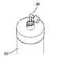
Translated fromKorean도 1은 종래 필터카트리지의 사시도이다.1 is a perspective view of a conventional filter cartridge.
도 2 및 도 3은 본 발명에 의한 필터카트리지 결합구조의 분해사시도이다.2 and 3 are exploded perspective view of the filter cartridge coupling structure according to the present invention.
도 4는 본 발명에 의한 필터카트리지 결합구조에 적용되는 상판의 사시도이다.Figure 4 is a perspective view of the top plate applied to the filter cartridge coupling structure according to the present invention.
도 5는 본 발명에 의한 필터카트리지 결합구조에 적용되는 하판의 사시도이다.5 is a perspective view of the lower plate applied to the filter cartridge coupling structure according to the present invention.
도 6은 본 발명에 의한 필터카트리지 결합구조에 적용되는 체결브라켓의 분해사시도이다.6 is an exploded perspective view of the fastening bracket applied to the filter cartridge coupling structure according to the present invention.
도 7은 본 발명에 의한 필터카트리지 결합구조의 단면도이다.7 is a cross-sectional view of the filter cartridge coupling structure according to the present invention.
<도면의 주요부분에 대한 부호의 설명><Description of the symbols for the main parts of the drawings>
100 : 플로우 키트120 : 키트유로100: flow kit 120: kit euro
122 : 출수구124 : 입수구122: outlet 124: inlet
200 : 플레이트 밸브210 : 상판200: plate valve 210: top plate
220 : 하판300 : 체결브라켓220: lower plate 300: tightening bracket
310 : 브라켓 하우징320 : 커넥터310: bracket housing 320: connector
330 : 실링시트340 : 오링330: sealing sheet 340: O-ring
400 : 모듈헤드 하우징410 : 체결홀400: module head housing 410: fastening hole
420 : 슬라이드 블록430 : 고정돌기420: slide block 430: fixed protrusion
500 : 필터카트리지510 : 입수홀500: filter cartridge 510: inlet hole
520 : 정수홀530 : 생활용수홀520: water purification hole 530: living water hole
540 : 체결블록542 : 체결돌기540: fastening block 542: fastening protrusion
543 : 고정홈543: fixing groove
본 발명은 정수기용 필터카트리지 결합구조에 관한 것으로, 보다 상세하게는 필터카트리지를 모듈헤드 하우징에 장착시켰을 때 물이 유입 및 유출되는 유로가 개방되고 상기 필터카트리지를 모듈헤드 하우징으로부터 분리시켰을 때 상기 유로가 폐쇄되도록 구성되는 정수기용 필터카트리지 결합구조에 관한 것이다.The present invention relates to a filter cartridge coupling structure for a water purifier, and more particularly, when a filter cartridge is mounted in a module head housing, a flow path through which water flows in and out is opened, and the flow path is separated when the filter cartridge is separated from the module head housing. It relates to a filter cartridge coupling structure for the water purifier is configured to be closed.
최근에는 수도수를 다단계의 여과 과정(Filtering)을 경유하여 얻어지는 양질의 음용수를 제공하는 정수기가 식당, 가정은 물론 기업, 공사 현장에 까지 널리 보급되어 사용되고 있는 실정이다.Recently, water purifiers that provide high-quality drinking water obtained through multi-step filtration of tap water have been widely used in restaurants, homes, businesses, and construction sites.
정수기에는 수도수로부터 미생물, 미립자, 광물질 또는 냄새를 제거하기 위 한 다수의 여과단계를 행하는 필터카트리지를 정수기내에 설치하여 수도수가 통과하면서 여과된 정수는 저수조에 저장된다.In the water purifier, a filter cartridge which performs a plurality of filtration steps to remove microorganisms, particulates, minerals or odors from tap water is installed in the water purifier, and the purified water is stored in the water tank while the tap water passes.
정수기에 장착되는 필터의 수명은 수질에 따라서 차이가 나겠지만 소정 기간의 여과과정을 거치게 되면 필터 내에는 이물이 쌓이게 되고 이로 인하여 필터 기능이 저하되기 때문에 필터가 내장된 필터카트리지를 주기적으로 교환을 해주어야 한다.The life of the filter installed in the water purifier may vary depending on the water quality, but after a certain period of filtration, foreign matter will accumulate in the filter and the filter function will be degraded. Therefore, the filter cartridge with the built-in filter should be replaced periodically. .
그런데 종래의 필터카트리지는 도 1에 도시된 바와 같이 필터카트리지(20)의 상부에 형성된 물 유입구에 별도의 피팅(fitting)(30)을 연결한 다음 수돗물 유입관을 연결하여 사용하여 왔었는데 이것은 소정기간이 지나 필터카트리지를 교체하기 위해서는 별도 공구인 니플을 이용하여 피팅을 분리한 다음 필터카트리지를 교체하여야 하므로 일반 소비자들이 교체하기에는 너무 어려워 전문가에게 별도로 비용을 지불하면서 교체해야하는 문제점이 있었다.By the way, the conventional filter cartridge has been used by connecting a separate fitting (30) to the water inlet formed in the upper portion of the
또한 필터카트리지 교체 시 수도수의 누출을 방지하기 위하여 유수관의 적정한 위치에 설치된 개폐밸브를 폐쇄위치로 조작한 다음 교체작업을 수행해야만 되므로 교체작업 시 별도의 개폐밸브를 여러 번 조작하여야 하는 번거로운 문제점이 있었다.In addition, in order to prevent leakage of tap water when replacing the filter cartridge, it is necessary to operate the on / off valve installed at the proper position of the water supply pipe to the closed position, and then perform the replacement work. There was this.
본 발명은 상기와 같은 문제점을 해결하기 위하여 제안된 것으로, 별도의 공구 없이도 필터카트리지를 용이하게 교체할 수 있으며, 필터카트리지가 장착되었을 때에만 유로가 개방되도록 구성됨으로써 상기 필터카트리지 교체 시 유로 개폐밸브를 조작할 필요가 없는 필터카트리지 결합구조를 제공하는데 목적이 있다.The present invention has been proposed to solve the above problems, it is possible to easily replace the filter cartridge without a separate tool, the flow path opening and closing valve when replacing the filter cartridge is configured to open only when the filter cartridge is mounted The purpose is to provide a filter cartridge coupling structure that does not need to be manipulated.
상기와 같은 목적을 달성하기 위한 본 발명에 의한 필터카트리지 결합구조는, 출수구 및 입수구가 외부에 형성되는 플로우 키트; 상호 간의 회전 각도에 따라 내부 유로를 개방시키거나 폐쇄시키도록 적층되는 상판과 하판으로 구성되며, 상기 상판이 상기 출수구 및 입수구와 대응되는 부위에 고정 결합되는 플레이트 밸브; 상기 하판과 일체로 회전되는 구조로 결합되는 체결브라켓; 상기 플레이트 밸브와 체결브라켓이 내부에 장착되도록, 상기 플로우 키트와 결합되는 모듈헤드 하우징; 및 상기 플레이트 밸브의 내부 유로와 연통되도록 상기 모듈헤드 하우징에 회전 방식으로 결합되며, 상기 모듈헤드 하우징과 결합되는 방향으로 회전될 때 상기 플레이트 밸브의 내부 유로가 개방되도록 상기 체결브라켓을 회전시키고, 상기 모듈헤드 하우징과 분리되는 방향으로 회전될 때 상기 플레이트 밸브의 내부 유로가 폐쇄되도록 상기 체결브라켓을 회전시키는 필터카트리지; 를 포함하여 구성된다.Filter cartridge coupling structure according to the present invention for achieving the above object, the flow kit is formed in the outlet and the inlet opening; A plate valve having an upper plate and a lower plate stacked to open or close the inner flow path according to rotation angles between the upper and lower plates, wherein the upper plate is fixedly coupled to a portion corresponding to the outlet and the inlet; A fastening bracket coupled to the lower plate and integrally rotated; A module head housing coupled to the flow kit such that the plate valve and the fastening bracket are mounted therein; And rotationally coupled to the module head housing so as to communicate with an inner flow path of the plate valve, and rotating the fastening bracket to open the inner flow path of the plate valve when rotated in a direction coupled with the module head housing. A filter cartridge for rotating the fastening bracket so that the inner flow path of the plate valve is closed when rotated in a direction separate from the module head housing; It is configured to include.
상기 필터카트리지는, 상단이 상기 모듈헤드 하우징 내부로 인입된 후 회전함으로써 상기 모듈헤드 하우징과 결합되도록 형성되며, 상기 모듈헤드 하우징 내부로 인입되는 부위의 외주면에 측방으로 돌출되는 체결블록이 형성되고, 상기 모듈헤드 하우징은, 상기 체결블록이 내부로 인입된 후 상기 필터카트리지가 회전될 때 상기 체결블록이 안착되어 슬라이딩되는 슬라이드 블록이 형성될 수 있다.The filter cartridge is formed to be coupled to the module head housing by rotating the upper end is introduced into the module head housing, the fastening block protruding laterally on the outer circumferential surface of the portion introduced into the module head housing, The module head housing may have a slide block in which the fastening block is seated and slides when the filter cartridge is rotated after the fastening block is inserted into the module head housing.
상기 체결브라켓은 상기 필터카트리지의 상단이 상기 모듈헤드 하우징 내부로 인입되었을 때 상기 체결블록과 대응되는 부위에 체결홈이 형성되고, 상기 체결블록은 상기 필터카트리지의 상단이 상기 모듈헤드 하우징 내부로 인입될 때 상기 체결홈으로 인입되는 체결돌기가 형성될 수 있다.The fastening bracket has a fastening groove formed at a portion corresponding to the fastening block when the upper end of the filter cartridge is inserted into the module head housing, and the fastening block is inserted into the module head housing at the upper end of the filter cartridge. When the fastening protrusions are introduced into the fastening groove may be formed.
상기 체결브라켓은, 상기 필터카트리지와 일체로 회전하도록 체결되는 브라켓 하우징; 및 상기 플레이트 필터의 내부 유로를 상기 필터카트리지에 연통시키는 관통구가 형성되어 상기 브라켓 하우징에 결합되며, 상기 하판과 결합되는 걸림돌기가 상측에 형성되는 커넥터; 를 포함하여 구성될 수 있다.The fastening bracket may include a bracket housing fastened integrally with the filter cartridge; And a through hole through which an inner flow path of the plate filter communicates with the filter cartridge, is coupled to the bracket housing, and a connector having an engaging protrusion coupled to the lower plate is formed at an upper side thereof. It may be configured to include.
상기 브라켓 하우징은, 중심축을 회전축으로 하여 회전 가능한 구조로 상기 플로우 키트에 결합될 수 있다.The bracket housing may be coupled to the flow kit in a rotatable structure with a central axis as the rotation axis.
상기 걸림돌기는 상기 커넥터의 상측 외주면에 형성되며, 상기 브라켓 하우징은 상기 커넥터가 장착되었을 때 상기 걸림돌기의 하단부가 인입되는 걸림홈이 형성될 수 있다.The locking protrusion may be formed on an upper outer circumferential surface of the connector, and the bracket housing may have a locking groove into which the lower end of the locking protrusion is inserted when the connector is mounted.
상기 체결브라켓은, 상기 관통구와 대응되는 부위에 유로구가 형성되어 상기 하판의 저면과 커넥터의 저면 사이에 결합되는 실링시트를 더 포함할 수 있다.The fastening bracket may further include a sealing sheet formed at a portion corresponding to the through-hole so as to be coupled between the bottom of the lower plate and the bottom of the connector.
상기 상판은 외주면에 상판 위치결정홈이 형성되고, 상기 플로우키트는 상기 상판이 결합될 때 상기 상판 위치결정홈으로 인입되는 상판 위치결정돌기가 형성되며, 상기 하판은 외주면에 하판 위치결정홈이 형성되고, 상기 체결브라켓은 상기 하판이 장착될 때 상기 하판 위치결정홈으로 인입되는 하판 위치결정돌기가 형성될 수 있다.The upper plate is formed with an upper plate positioning groove on the outer circumferential surface, the flow kit is formed with an upper plate positioning projection which is introduced into the upper plate positioning groove when the upper plate is coupled, the lower plate is formed with a lower plate positioning groove on the outer peripheral surface The fastening bracket may be provided with a lower plate positioning projection that is inserted into the lower plate positioning groove when the lower plate is mounted.
상기 상판과 하판은 세라믹 또는 플라스틱으로 제작될 수 있다.The upper and lower plates may be made of ceramic or plastic.
이하 첨부된 도면을 참조하여 본 발명에 의한 필터카트리지 결합구조의 실시예를 상세히 설명한다.Hereinafter, embodiments of the filter cartridge coupling structure according to the present invention will be described in detail with reference to the accompanying drawings.
도 2 및 도 3은 본 발명에 의한 필터카트리지 결합구조의 분해사시도이고, 도 4 및 도 5는 각각 본 발명에 의한 필터카트리지 결합구조에 적용되는 상판과 하판의 사시도이며, 도 6은 본 발명에 의한 필터카트리지 결합구조에 적용되는 체결브라켓의 분해사시도이다.2 and 3 is an exploded perspective view of the filter cartridge coupling structure according to the present invention, Figures 4 and 5 are perspective views of the upper and lower plates respectively applied to the filter cartridge coupling structure according to the present invention, Figure 6 is Is an exploded perspective view of the fastening bracket applied to the filter cartridge coupling structure.
도 2 및 도 3에 도시된 바와 같이 본 발명에 의한 필터카트리지 결합구조는, 물이 흐르는 키트 유로(120)(도 7 참조)가 내부에 형성된 플로우 키트(100)와, 상기 플로우 키트(100)로부터 외부로 물이 유출되거나 유입되는 것을 제어하기 위한 플레이트 밸브(200)와, 수직 중심축을 회전축으로 하는 회전운동을 통해 상기 플레 이트 밸브(200)의 내부 유로를 개폐시키는 체결브라켓(300)과, 상기 플레이트 밸브(200)와 체결브라켓(300)이 내부에 인입되도록 상기 플로우 키트(100)에 결합되는 모듈헤드 하우징(400)과, 상기 체결브라켓(300)과 연결되도록 상기 모듈헤드 하우징(400)에 결합되는 필터카트리지(500)를 포함하여 구성된다.As shown in FIG. 2 and FIG. 3, the filter cartridge coupling structure according to the present invention includes a
이때 본 발명에 의한 필터카트리지 결합구조는, 상기 필터카트리지(500)가 상기 모듈헤드 하우징(400)에 결합되었을 때 상기 플로우 키트(100)의 키트 유로(120)가 외부와 연통되도록 상기 플레이트 밸브(200)의 내부 유로가 개방되고, 상기 필터카트리지(500)가 상기 모듈헤드 하우징(400)으로부터 분리되었을 때 상기 플로우 키트(100)의 키트 유로(120)가 외부와 격리되도록 상기 플레이트 밸브(200)의 내부 유로가 폐쇄되도록 구성된다.At this time, the filter cartridge coupling structure according to the present invention, when the
이하, 상기와 같은 동작을 가능하게 하기 위한 각 부의 구성을 보다 상세히 설명한다.Hereinafter, the configuration of each part for enabling the above operation will be described in more detail.
상기 플로우 키트(100)는 일정한 방향으로 물이 흐를 수 있도록 내부에 키트 유로(120)가 형성되며, 저면에 출수구(122)와 입수구(124)가 형성된다(도 7 참조). 상기 플로우 키트(100)는 종래에 사용되고 있는 플로우 키트(100)와 구성 및 동작이 동일하므로, 이에 대한 상세한 설명은 생략한다.The
상기 플레이트 밸브(200)는 수직방향으로 적층되는 상판(210)과 하판(220)으로 구성된다.The
상기 상판(210)에는 도 4에 도시된 바와 같이 상기 플로우 키트(100)로부터 물이 유입되는 상측 입수유로(212)와, 필터카트리지(500)를 거쳐 정수된 물을 상기 플로우 키트(100)로 보내기 위한 상측 정수유로(214)와, 상기 필터카트리지(500)로부터 인출되는 생활용수를 상기 플로우 키트(100)로 보내기 위한 상측 생활용수유로(216)가 각각 형성된다.As shown in FIG. 4, the
또한 상기 하판(220)에는 상기 상측 입수유로(212)와 상측 정수유로(214)와 상측 생활용수유로(216)와 대응되는 하측 입수유로(222), 하측 정수유로(224), 하측 생활용수유로(226)가 각각 형성된다. 본 실시예에서는 상기 필터카트리지(500)에 물이 유입되는 입수홀(510)과 정수와 생활용수를 구분하여 각각 별도로 인출하도록 정수홀(520)과 생활용수홀(530)이 각각 별도로 구성되어 있으므로, 상기 상판(210)과 하판(220)에도 각각 정수유로(214, 224)와 생활용수유로(216, 226)가 형성되어 있으나, 상기 필터카트리지(500)가 정수만을 인출하도록 구성되는 경우 상기 생활용수유로(216, 226)는 생략될 수 있다.In addition, the
이때, 상기 상판(210)과 하판(220)은 적층된 상태를 유지하면서 수직 중심축을 회전축으로 하여 각각 독립적으로 회전 가능하므로, 상호 간의 회전 각도에 따라 대응되는 유로들이 동일 수직선상에 위치되어 개방되거나 서로 어긋나게 위치되어 폐쇄될 수 있도록 구성된다.At this time, the
또한, 상기 상판(210)과 하판(220) 사이로 물이 새지 아니하도록, 상기 상판(210)과 하판(220)은 세라믹, 플라스틱 등과 같이 표면이 매우 매끄럽게 가공될 수 있는 재료로 제작됨이 바람직하다.In addition, the
상기 상판(210)의 외주면에는 수직방향으로 길이를 갖는 상판 위치결정홈(218)이 형성되고, 상기 플로우 키트(100)의 하측 부위에는 상기 상판(210)이 결합될 때 상기 상판 위치결정홈(218)으로 인입되는 상판 위치결정돌기(미도시)가 형성된다. 따라서 상기 상판(210)은 항상 일정한 방향으로만 상기 플로우 키트(100)에 결합되므로, 상기 상판(210)을 상기 플로우 키트(100)에 결합시킬 때 플로우 키트(100)에 형성된 출수구(122) 및 입수구(124)와 상기 상판(210)에 형성된 각 유로(212, 214, 216)를 일일이 맞출 필요가 없어 조립이 간편해진다.An upper
또한 상기 하판(220)의 외주면에는 하판 위치결정홈(228)이 형성되고, 상기 체결브라켓(300)의 상측 부위에는 상기 하판(220)이 장착될 때 상기 하판 위치결정홈(228)으로 인입되는 하판 위치결정돌기(도 2의 312)가 형성된다. 이와 같이 상기 하판(220) 역시 결합 방향이 일정하게 설정되어 있으므로 상기 체결브라켓(300)에 조립이 잘못될 우려가 없게 된다.In addition, a lower
상기 체결브라켓(300)은, 상기 필터카트리지(500)와 일체로 회전하도록 체결되는 브라켓 하우징(310)과, 상기 플레이트 필터의 내부 유로를 상기 필터카트리지(500)에 연통시키는 관통구(322)가 형성되어 상기 브라켓 하우징(310)에 결합되는 커넥터(320)와, 상기 관통구(322)와 대응되는 부위에 유로구(332)가 형성되어 상기 하판(220)의 저면과 커넥터(320)의 저면 사이에 결합되는 실링시트(330)와, 상기 커넥터(320)와 브라켓 하우징(310) 사이로 물이 새지 아니하도록 상기 커넥 터(320)의 하단부에 결합되는 오링(340)을 포함하여 구성된다.The
상기 브라켓 하우징(310)은, 상기 커넥터(320)의 하측 끝단이 가운데 부위를 관통하여 상기 필터카트리지(500)와 연통되도록 중공 형상으로 형성되며, 상기 필터카트리지(500)가 중심축을 회전축으로 하여 회전함에 따라 상기 필터카트리지(500)와 일체로 회전될 수 있도록 회전 가능한 구조로 상기 플로우 키트(100)에 결합된다.The
상기 실링시트(330)는 상기 하판(220)의 저면과 커넥터(320)의 상면 사이로 물이 새지 아니하도록 하는 패킹 역할을 하는 구성요소로서, 상기 하판(220)을 지나는 물의 유로 확보를 위해 상기 하판(220)의 각 유로(222, 224, 226)와 대응되는 부위에 유로구(332)가 형성된다. 또한 상기 하판(220)의 각 유로(222, 224, 226)와 상기 유로구(332)를 지나는 물이 상기 하판(220)의 저면과 상기 실링시트(330)의 상면 사이로 유출되지 아니하도록, 상기 실링시트(330)의 각 유로구(332) 주변을 감싸는 형상으로 상향 돌출되는 실링돌출부(334)가 형성된다.The sealing
상기 커넥터(320)는 상기 하판(220)과 브라켓 하우징(310)이 일체로 회전되도록 상기 하판(220)과 브라켓을 연결시키는 구성요소로서, 상측 외주면에는 걸림돌기(324)가 형성되며, 상기 브라켓 하우징(310)에는 상기 걸림돌기(324)의 하단부가 슬라이딩 방식으로 인입되는 걸림홈(314)이 형성된다. 즉, 상기 걸림돌기(324)와 걸림홈(314)은 상기 커넥터(320)와 브라켓 하우징(310)이 일체로 회전될 수 있 도록 회전력을 전달하는 역할을 한다.The
또한 상기 걸림돌기(324)는 상향으로 돌출되도록 형성되고, 상기 하판(220)의 저면에는 도 5에 도시된 바와 같이 상기 각 걸림돌기(324)와 대응되는 부위에 삽입홀(229)이 각각 형성되어, 상기 커넥터(320)와 하판(220)은 일체로 회전되도록 결합된다.In addition, the locking
결과적으로, 상기 필터카트리지(500)와 브라켓 하우징(310), 커넥터(320), 하판(220)은 일체로 회전하게 된다.As a result, the
상기 모듈헤드 하우징(400)은 상기 체결브라켓(300)에 안착된 상기 플레이트 밸브(200)가 상기 플로우 키트(100)의 저면에 밀착되도록 상기 플레이트 밸브(200)와 체결브라켓(300)의 결합위치를 고정시키기 위한 구성요소로서, 상기 체결브라켓(300)의 하측 부위에는 상기 필터카트리지(500)의 상단이 인입될 수 있도록 개구부가 형성되어 있다.The
따라서 상기 필터카트리지(500)는 상단이 상기 개구부를 관통하여 상기 브라켓 하우징(310)과 일체로 회전 가능한 구조로 결합된다. 또한 상기 필터카트리지(500)는, 상단이 상기 모듈헤드 하우징(400) 내부로 인입된 이후 수직 중심축을 회전축으로 하여 회전함으로써 상기 모듈헤드 하우징(400)과 결합되도록 구성된다.Therefore, the
이와 같은 구성이 가능해지도록, 상기 필터카트리지(500)는 상기 모듈헤드 하우징(400) 내부로 인입되는 부위 즉, 상단측 외주면에 측방으로 돌출되는 체결블록(540)이 형성되고, 상기 모듈헤드 하우징(400)은 상기 체결블록(540)이 내부로 인입된 후 상기 필터카트리지(500)가 회전될 때 상기 체결블록(540)이 상면에 안착되어 슬라이딩되는 슬라이드 블록(420)이 형성된다.In order to enable such a configuration, the
즉, 상기 체결블록(540)이 상기 모듈헤드 하우징(400)의 개구부 내측면에 형성된 체결홀(410)을 지나도록 상기 필터카트리지(500)의 상단이 상기 모듈헤드 하우징(400) 내부로 인입되면, 상기 체결블록(540)의 상면에 형성된 체결돌기(542)가 상기 체결브라켓(300)의 하측 끝단에 형성된 체결홈(302)으로 인입되어 상기 필터카트리지(500)와 체결브라켓(300)이 일체로 회전될 수 있도록 체결된다. 또한, 상기 체결돌기(542)가 체결홈(302)으로 인입된 상태에서 상기 필터카트리지(500)가 회전되면, 상기 체결블록(540)이 상기 슬라이드 블록(420)의 상면을 타고 슬라이딩됨으로써 상기 필터카트리지(500)가 상기 모듈헤드 하우징(400)으로부터 하향으로 빠지지 아니하게 된다.That is, when the upper end of the
또한, 상기 체결블록(540)의 저면에는 고정홈(543)이 형성되고, 상기 체결블록(540)의 슬라이딩이 완료되었을 때 즉, 상기 필터카트리지(500)의 회전이 완료되었을 때 상기 고정홈(543)과 대응되는 부위의 상기 슬라이드 블록(420)의 상면에는 상기 고정홈(543)에 인입되는 고정돌기(430)가 형성되어, 사용자는 상기 고정돌기(430)가 고정홈(543)에 인입되는 클릭감을 통해 상기 필터카트리지(500)가 끝까지 회전되었음을 인지할 수 있게 된다. 물론, 상기 고정돌기(430)는 상기 체결블록(540)의 슬라이딩 동작에 방해가 되지 아니하도록 매우 낮은 높이로 형성되어야 한다.In addition, the bottom of the
이하 첨부된 도면을 참조하여 본 발명에 의한 필터카트리지 결합구조의 동작에 대하여 상세히 설명한다.Hereinafter, the operation of the filter cartridge coupling structure according to the present invention will be described in detail with reference to the accompanying drawings.
도 7은 본 발명에 의한 필터카트리지 결합구조의 단면도이다.7 is a cross-sectional view of the filter cartridge coupling structure according to the present invention.
도 7에 도시된 바와 같이 상기 브라켓 하우징(310)이 상기 플로우 키트(100)에 결합되면, 상기 실링시트(330)의 상면이 상기 하판(220)의 저면에 밀착되며, 상기 커넥터(320)의 걸림돌기(324) 상측 끝단은 상기 실링시트(330)의 커넥터홀(336)을 관통하여 상기 하판(220)의 삽입홀(229)에 인입된다. 또한, 필터카트리지(500)가 상기 모듈헤드 하우징(400)에 결합되면, 상기 커넥터(320)의 하단 일부가 상기 필터카트리지(500)의 정수홀(520)로 인입되어 상기 체결브라켓(300)과 필터카트리지(500)가 상호 연통되고, 상기 필터카트리지(500)의 상단 외주면에 형성된 체결돌기(542)가 상기 브라켓 하우징(310)의 체결홈(302)에 인입되어 상기 브라켓 하우징(310)과 일체로 회전하게 된다(도 2 참조).As shown in FIG. 7, when the
이때 상기 상판(210)은 상기 플로우 키트(100)에 고정 결합되므로, 상기 필터카트리지(500)를 상기 모듈헤드 하우징(400)에 결합되는 방향으로 회전시키면, 상기 하판(220)이 회전되어 상기 하판(220)의 하측 입수유로(222)와 하측 정수유로(224)와 하측 생활용수유로(226)가 각각 상판(210)의 상측 입수유로(212)와 상측 정수유로(214)와 상측 생활용수유로(216)와 일치하게 된다. 즉, 상기 카트리지필터를 상기 모듈헤드 하우징(400)에 결합시키는 과정을 통해 상기 플레이트 밸브(200)의 내부 유로가 개방되어 상기 플로우 키트(100)와 상기 필터카트리지(500)가 연통 되게 된다.In this case, since the
반대로, 상기 필터카트리지(500)를 상기 모듈헤드 하우징(400)으로부터 분리되는 방향으로 회전시키면, 상기 하판(220)이 반대로 회전되어 상기 하판(220)의 하측 입수유로(222)와 하측 정수유로(224)와 하측 생활용수유로(226)가 각각 상판(210)의 상측 입수유로(212)와 상측 정수유로(214)와 상측 생활용수유로(216)와 어긋나도록 배치된다. 즉, 상기 카트리지필터를 상기 모듈헤드 하우징(400)으로부터 분리시키는 과정을 통해 상기 플레이트 밸브(200)의 내부 유로가 폐쇄되어 상기 플로우 키트(100)와 상기 필터카트리지(500)를 연통시키는 유로가 연통되지 아니하게 된다.On the contrary, when the
이와 같이 본 발명에 의한 필터카트리지 결합구조는 필터카트리지(500)를 교체할 때 상기 플레이트 밸브(200)가 자동으로 개폐되므로, 필터카트리지(500) 개폐 시 플로우 키트(100) 내부의 물이 외부로 인출될 우려가 없어지고, 필터카트리지(500) 교체 시 별도의 공구를 이용하여 유로를 개폐할 필요가 없으므로 필터카트리지(500) 교체가 매우 간편해진다는 장점이 있다.As described above, the filter cartridge coupling structure according to the present invention automatically opens and closes the
이상, 본 발명을 바람직한 실시 예를 사용하여 상세히 설명하였으나, 본 발명의 범위는 특정 실시 예에 한정되는 것은 아니며, 첨부된 특허청구범위에 의하여 해석되어야 할 것이다. 또한, 이 기술분야에서 통상의 지식을 습득한 자라면, 본 발명의 범위에서 벗어나지 않으면서도 많은 수정과 변형이 가능함을 이해하여야 할 것이다.As mentioned above, although this invention was demonstrated in detail using the preferable embodiment, the scope of the present invention is not limited to a specific embodiment, Comprising: It should be interpreted by the attached Claim. In addition, those skilled in the art should understand that many modifications and variations are possible without departing from the scope of the present invention.
본 발명에 의한 정수기용 필터카트리지 결합구조는, 별도의 공구 없이도 필터카트리지를 용이하게 교체할 수 있고, 필터카트리지가 장착되었을 때에만 유로가 개방되므로 필터카트리지 교체 시 유로 개폐밸브를 조작할 필요가 없으며, 필터카트리지 교체 시 플로우 키트 내의 물이 외부로 유출될 우려가 없어진다는 장점이 있다.The filter cartridge coupling structure for the water purifier according to the present invention can easily replace the filter cartridge without a separate tool, and since the flow path is opened only when the filter cartridge is mounted, there is no need to operate the flow shutoff valve when replacing the filter cartridge. When replacing the filter cartridge, there is an advantage that the water in the flow kit is not leaked to the outside.
Claims (9)
Translated fromKoreanPriority Applications (1)
| Application Number | Priority Date | Filing Date | Title |
|---|---|---|---|
| KR1020060131411AKR100804302B1 (en) | 2006-12-20 | 2006-12-20 | Filter cartridge coupling structure for water purifier |
Applications Claiming Priority (1)
| Application Number | Priority Date | Filing Date | Title |
|---|---|---|---|
| KR1020060131411AKR100804302B1 (en) | 2006-12-20 | 2006-12-20 | Filter cartridge coupling structure for water purifier |
Publications (1)
| Publication Number | Publication Date |
|---|---|
| KR100804302B1true KR100804302B1 (en) | 2008-02-18 |
Family
ID=39382321
Family Applications (1)
| Application Number | Title | Priority Date | Filing Date |
|---|---|---|---|
| KR1020060131411AActiveKR100804302B1 (en) | 2006-12-20 | 2006-12-20 | Filter cartridge coupling structure for water purifier |
Country Status (1)
| Country | Link |
|---|---|
| KR (1) | KR100804302B1 (en) |
Cited By (35)
| Publication number | Priority date | Publication date | Assignee | Title |
|---|---|---|---|---|
| WO2010017003A3 (en)* | 2008-08-08 | 2010-04-08 | Kx Technologies Llc | Push filter with floating key lock |
| KR101002092B1 (en) | 2009-02-20 | 2010-12-16 | 권진철 | Water Purifier Filter Installation Structure |
| KR101148053B1 (en) | 2010-07-02 | 2012-05-24 | (주)워피온 | Filter Assembly for Water Purifier |
| WO2012086892A1 (en)* | 2010-12-21 | 2012-06-28 | Kwon Jin Chul | Filter unit |
| KR101176315B1 (en) | 2010-12-21 | 2012-08-23 | 권진철 | Filter unit |
| KR101239330B1 (en)* | 2011-05-13 | 2013-03-05 | 정휘동 | Filter unit and filter assembly using thereof |
| WO2013100478A1 (en)* | 2011-12-28 | 2013-07-04 | Coway Co., Ltd. | Water purifying filter assembly module and water purifier having the same |
| KR101284444B1 (en)* | 2010-12-28 | 2013-07-09 | 권진철 | Reverse osmotic membrane filter unit |
| KR200467907Y1 (en) | 2011-01-05 | 2013-07-23 | 권진철 | Filter unit |
| KR101318423B1 (en) | 2011-06-24 | 2013-10-15 | 위니맥스 주식회사 | Water filter assembly and refrigerator and water purifier having the same |
| KR101447907B1 (en)* | 2014-05-26 | 2014-10-10 | (주)한독크린텍 | Water Purification Filter Assembly |
| US9233322B1 (en) | 2008-08-08 | 2016-01-12 | Kx Technologies Llc | Push filter with floating key lock |
| KR101712971B1 (en) | 2016-09-28 | 2017-03-07 | (주)씨디씨뉴매틱 | Filter connection apparatus for water purifier piping |
| US9901852B2 (en) | 2008-08-08 | 2018-02-27 | Kx Technologies Llc | Push filter with floating key lock |
| US10040703B2 (en) | 2008-08-08 | 2018-08-07 | Kx Technologies Llc | Reverse osmosis push filter with floating key lock |
| CN108567338A (en)* | 2018-06-25 | 2018-09-25 | 金华市宏昌电器有限公司 | A kind of integrating water route plate |
| CN110538502A (en)* | 2019-09-27 | 2019-12-06 | 空山科技有限公司 | a filter device |
| KR20200027678A (en)* | 2018-09-05 | 2020-03-13 | 주식회사 엠씨엠 | Connecting structure for filter and water purifier having the same |
| KR20210123935A (en)* | 2020-04-06 | 2021-10-14 | 엘지전자 주식회사 | water purifying apparatus refrigerator |
| US11273397B2 (en) | 2018-09-13 | 2022-03-15 | Electrolux Home Products, Inc. | Filter base for electronic connection to mating filter housing assembly |
| USD946703S1 (en) | 2019-11-18 | 2022-03-22 | Electrolux Home Products, Inc. | Filter cartridge |
| USD946699S1 (en) | 2019-11-18 | 2022-03-22 | Electrolux Home Products, Inc. | Filter cartridge |
| USD946701S1 (en) | 2019-11-18 | 2022-03-22 | Electrolux Home Products, Inc. | Filter cartridge |
| USD946700S1 (en) | 2019-11-18 | 2022-03-22 | Electrolux Home Products, Inc. | Filter cartridge |
| USD946702S1 (en) | 2019-11-18 | 2022-03-22 | Electrolux Home Products, Inc. | Filter cartridge |
| USD948659S1 (en) | 2019-11-18 | 2022-04-12 | Electrolux Home Products, Inc. | Filter cartridge |
| USD948660S1 (en) | 2019-11-18 | 2022-04-12 | Electrolux Home Products, Inc. | Filter cartridge |
| KR20220085318A (en)* | 2020-12-15 | 2022-06-22 | 엘지전자 주식회사 | Water purifier |
| US11413560B2 (en) | 2019-11-18 | 2022-08-16 | Electrolux Home Products, Inc. | Push filter with floating key lock |
| US11426685B2 (en) | 2008-08-08 | 2022-08-30 | Kx Technologies Llc | Push filter with floating key lock |
| USD969270S1 (en) | 2019-11-18 | 2022-11-08 | Electrolux Home Products, Inc. | Filter cartridge |
| USD987772S1 (en) | 2020-07-02 | 2023-05-30 | Qingdao Ecopure Filter Co., Ltd. | Water filter |
| US11872510B2 (en) | 2021-07-01 | 2024-01-16 | Qingdao Ecopure Filter Co., Ltd | Water filter |
| USD1016970S1 (en) | 2021-09-03 | 2024-03-05 | Qingdao Ecopure Filter Co., Ltd | Water filter |
| USD1019884S1 (en) | 2021-08-03 | 2024-03-26 | Qingdao Ecopure Filter Co., Ltd. | Water filter |
Citations (5)
| Publication number | Priority date | Publication date | Assignee | Title |
|---|---|---|---|---|
| US5154823A (en) | 1991-10-30 | 1992-10-13 | Woon-Hawk Engineering Plastics, Inc. | Filter apparatus and distributor plate therefor |
| KR19990012584U (en)* | 1997-09-10 | 1999-04-06 | 이종민 | Water Direct Type Water Purifier |
| US20050092661A1 (en) | 2002-09-09 | 2005-05-05 | William Warren | Single-use long-life faucet-mounted water filtration devices |
| KR200392670Y1 (en) | 2005-05-12 | 2005-08-17 | 김근태 | connect structure of a filter-cartrige for clean water appliance |
| KR20060029491A (en)* | 2004-10-01 | 2006-04-06 | 삼성전자주식회사 | Water Purifier |
- 2006
- 2006-12-20KRKR1020060131411Apatent/KR100804302B1/enactiveActive
Patent Citations (5)
| Publication number | Priority date | Publication date | Assignee | Title |
|---|---|---|---|---|
| US5154823A (en) | 1991-10-30 | 1992-10-13 | Woon-Hawk Engineering Plastics, Inc. | Filter apparatus and distributor plate therefor |
| KR19990012584U (en)* | 1997-09-10 | 1999-04-06 | 이종민 | Water Direct Type Water Purifier |
| US20050092661A1 (en) | 2002-09-09 | 2005-05-05 | William Warren | Single-use long-life faucet-mounted water filtration devices |
| KR20060029491A (en)* | 2004-10-01 | 2006-04-06 | 삼성전자주식회사 | Water Purifier |
| KR200392670Y1 (en) | 2005-05-12 | 2005-08-17 | 김근태 | connect structure of a filter-cartrige for clean water appliance |
Cited By (59)
| Publication number | Priority date | Publication date | Assignee | Title |
|---|---|---|---|---|
| US8673146B2 (en) | 2008-08-08 | 2014-03-18 | Kx Technologies Llc | Push filter with floating key lock |
| US11433327B2 (en) | 2008-08-08 | 2022-09-06 | Kx Technologies Llc | Filter housing with filter key attachment |
| US8137551B1 (en) | 2008-08-08 | 2012-03-20 | Kx Technologies, Llc | Push filter with floating key lock |
| US10857492B2 (en) | 2008-08-08 | 2020-12-08 | Kx Technologies Llc | Push filter with floating key lock |
| US10695698B2 (en) | 2008-08-08 | 2020-06-30 | Kx Technologies Llc | Reverse osmosis push filter with floating key lock |
| US10675571B2 (en) | 2008-08-08 | 2020-06-09 | Kx Technologies Llc | Filter housing with filter key attachment |
| US8366930B2 (en) | 2008-08-08 | 2013-02-05 | Kx Technologies, Llc | Push filter with floating key lock |
| WO2010017003A3 (en)* | 2008-08-08 | 2010-04-08 | Kx Technologies Llc | Push filter with floating key lock |
| US12083455B2 (en) | 2008-08-08 | 2024-09-10 | Kx Technologies Llc | Filter housing with filter key attachment |
| US11426685B2 (en) | 2008-08-08 | 2022-08-30 | Kx Technologies Llc | Push filter with floating key lock |
| US10207211B2 (en) | 2008-08-08 | 2019-02-19 | Kx Technologies Llc | Push filter with floating key lock |
| US12042752B2 (en) | 2008-08-08 | 2024-07-23 | Kx Technologies Llc | Push filter with floating key lock |
| US11045753B2 (en) | 2008-08-08 | 2021-06-29 | Kx Technologies Llc | Push filter with floating key lock |
| US11376530B2 (en) | 2008-08-08 | 2022-07-05 | Kx Technologies Llc | Reverse osmosis push filter with floating key lock |
| US10040703B2 (en) | 2008-08-08 | 2018-08-07 | Kx Technologies Llc | Reverse osmosis push filter with floating key lock |
| US9233322B1 (en) | 2008-08-08 | 2016-01-12 | Kx Technologies Llc | Push filter with floating key lock |
| US11845025B2 (en) | 2008-08-08 | 2023-12-19 | Kx Technologies Llc | Push filter with floating key lock |
| US9901852B2 (en) | 2008-08-08 | 2018-02-27 | Kx Technologies Llc | Push filter with floating key lock |
| US11958003B2 (en) | 2008-08-08 | 2024-04-16 | Kx Technologies Llc | Push filter with floating key lock |
| KR101002092B1 (en) | 2009-02-20 | 2010-12-16 | 권진철 | Water Purifier Filter Installation Structure |
| KR101148053B1 (en) | 2010-07-02 | 2012-05-24 | (주)워피온 | Filter Assembly for Water Purifier |
| KR101176315B1 (en) | 2010-12-21 | 2012-08-23 | 권진철 | Filter unit |
| WO2012086892A1 (en)* | 2010-12-21 | 2012-06-28 | Kwon Jin Chul | Filter unit |
| KR101284444B1 (en)* | 2010-12-28 | 2013-07-09 | 권진철 | Reverse osmotic membrane filter unit |
| KR200467907Y1 (en) | 2011-01-05 | 2013-07-23 | 권진철 | Filter unit |
| KR101239330B1 (en)* | 2011-05-13 | 2013-03-05 | 정휘동 | Filter unit and filter assembly using thereof |
| US8746003B2 (en) | 2011-06-24 | 2014-06-10 | Winimax Co., Ltd. | Water filter assembly and refrigerator and water purifier having the same |
| KR101318423B1 (en) | 2011-06-24 | 2013-10-15 | 위니맥스 주식회사 | Water filter assembly and refrigerator and water purifier having the same |
| WO2013100478A1 (en)* | 2011-12-28 | 2013-07-04 | Coway Co., Ltd. | Water purifying filter assembly module and water purifier having the same |
| KR101447907B1 (en)* | 2014-05-26 | 2014-10-10 | (주)한독크린텍 | Water Purification Filter Assembly |
| KR101712971B1 (en) | 2016-09-28 | 2017-03-07 | (주)씨디씨뉴매틱 | Filter connection apparatus for water purifier piping |
| CN108567338B (en)* | 2018-06-25 | 2024-01-16 | 浙江宏昌电器科技股份有限公司 | Integrated waterway plate |
| CN108567338A (en)* | 2018-06-25 | 2018-09-25 | 金华市宏昌电器有限公司 | A kind of integrating water route plate |
| KR20200027678A (en)* | 2018-09-05 | 2020-03-13 | 주식회사 엠씨엠 | Connecting structure for filter and water purifier having the same |
| KR102207308B1 (en)* | 2018-09-05 | 2021-01-25 | 주식회사 엠씨엠 | Connecting structure for filter and water purifier having the same |
| US11273397B2 (en) | 2018-09-13 | 2022-03-15 | Electrolux Home Products, Inc. | Filter base for electronic connection to mating filter housing assembly |
| US11865479B2 (en) | 2018-09-13 | 2024-01-09 | Electrolux Home Products, Inc. | Filter base for electronic connection to mating filter housing assembly |
| CN110538502A (en)* | 2019-09-27 | 2019-12-06 | 空山科技有限公司 | a filter device |
| USD948659S1 (en) | 2019-11-18 | 2022-04-12 | Electrolux Home Products, Inc. | Filter cartridge |
| USD946699S1 (en) | 2019-11-18 | 2022-03-22 | Electrolux Home Products, Inc. | Filter cartridge |
| US11413560B2 (en) | 2019-11-18 | 2022-08-16 | Electrolux Home Products, Inc. | Push filter with floating key lock |
| USD946703S1 (en) | 2019-11-18 | 2022-03-22 | Electrolux Home Products, Inc. | Filter cartridge |
| USD948660S1 (en) | 2019-11-18 | 2022-04-12 | Electrolux Home Products, Inc. | Filter cartridge |
| USD969270S1 (en) | 2019-11-18 | 2022-11-08 | Electrolux Home Products, Inc. | Filter cartridge |
| USD1065432S1 (en) | 2019-11-18 | 2025-03-04 | Electrolux Consumer Products, Inc. | Filter cartridge |
| USD946702S1 (en) | 2019-11-18 | 2022-03-22 | Electrolux Home Products, Inc. | Filter cartridge |
| USD946700S1 (en) | 2019-11-18 | 2022-03-22 | Electrolux Home Products, Inc. | Filter cartridge |
| USD946701S1 (en) | 2019-11-18 | 2022-03-22 | Electrolux Home Products, Inc. | Filter cartridge |
| KR20210123935A (en)* | 2020-04-06 | 2021-10-14 | 엘지전자 주식회사 | water purifying apparatus refrigerator |
| KR102436312B1 (en)* | 2020-04-06 | 2022-08-25 | 엘지전자 주식회사 | water purifying apparatus refrigerator |
| USD1080804S1 (en) | 2020-07-02 | 2025-06-24 | Qingdao Ecopure Filter Co., Ltd. | Water filter |
| USD987772S1 (en) | 2020-07-02 | 2023-05-30 | Qingdao Ecopure Filter Co., Ltd. | Water filter |
| US12162743B2 (en) | 2020-12-15 | 2024-12-10 | Lg Electronics Inc. | Liquid dispenser |
| KR102661752B1 (en)* | 2020-12-15 | 2024-04-26 | 엘지전자 주식회사 | Water purifier |
| KR20220085318A (en)* | 2020-12-15 | 2022-06-22 | 엘지전자 주식회사 | Water purifier |
| US12083460B2 (en) | 2021-07-01 | 2024-09-10 | Qingdao Ecopure Filter Co., Ltd. | Water filter |
| US11872510B2 (en) | 2021-07-01 | 2024-01-16 | Qingdao Ecopure Filter Co., Ltd | Water filter |
| USD1019884S1 (en) | 2021-08-03 | 2024-03-26 | Qingdao Ecopure Filter Co., Ltd. | Water filter |
| USD1016970S1 (en) | 2021-09-03 | 2024-03-05 | Qingdao Ecopure Filter Co., Ltd | Water filter |
Similar Documents
| Publication | Publication Date | Title |
|---|---|---|
| KR100804302B1 (en) | Filter cartridge coupling structure for water purifier | |
| KR100668767B1 (en) | Filter cartridge connector with self-locking valve and filter assembly comprising the same | |
| US8746003B2 (en) | Water filter assembly and refrigerator and water purifier having the same | |
| KR100873294B1 (en) | Filter assembly | |
| US10293287B2 (en) | Water filter assembly | |
| KR100761025B1 (en) | Filter cartridge connector with self-locking valve by opening and closing cover and filter assembly comprising the same | |
| KR20100081827A (en) | Water filter assembly and valve assembly and water purifier having the same | |
| US20070284296A1 (en) | Filter cartridge and head assembly with internal shutoff valve | |
| MX2007011738A (en) | Water purification filter easily replaced using a connector, and a water purification system using the same. | |
| KR20110007147A (en) | Modular drinking water filtration system with removable and replaceable spindle | |
| KR20110015520A (en) | Modular drinking water filtration system with replaceable cartridge ring | |
| KR20110007146A (en) | Modular drinking water filtration system with bottom stack cartridge | |
| KR101447907B1 (en) | Water Purification Filter Assembly | |
| KR200384558Y1 (en) | Attaching mechanism of filter assembly for water purifier | |
| KR200296361Y1 (en) | Filter assembly for water purifier | |
| US20040238428A1 (en) | Wet sump filter adapter | |
| KR101776256B1 (en) | The Piping Onebody Cover for Water purifier | |
| KR20150002961U (en) | A connector for water purifiers cartridge filter | |
| JP2000210661A (en) | Multiple way valve and water purifier | |
| JP3702530B2 (en) | Water purifier | |
| KR101206645B1 (en) | Filter Assembly with rise and fall type auto shut-off valve | |
| KR20060115436A (en) | Filter cartridge connection structure for water purifier | |
| KR200190745Y1 (en) | Filter assembly for rectifier | |
| KR0156714B1 (en) | Filtration device for water purifier | |
| KR101712971B1 (en) | Filter connection apparatus for water purifier piping |
Legal Events
| Date | Code | Title | Description |
|---|---|---|---|
| A201 | Request for examination | ||
| PA0109 | Patent application | Patent event code:PA01091R01D Comment text:Patent Application Patent event date:20061220 | |
| PA0201 | Request for examination | ||
| E902 | Notification of reason for refusal | ||
| PE0902 | Notice of grounds for rejection | Comment text:Notification of reason for refusal Patent event date:20070928 Patent event code:PE09021S01D | |
| E701 | Decision to grant or registration of patent right | ||
| PE0701 | Decision of registration | Patent event code:PE07011S01D Comment text:Decision to Grant Registration Patent event date:20080130 | |
| GRNT | Written decision to grant | ||
| PR0701 | Registration of establishment | Comment text:Registration of Establishment Patent event date:20080211 Patent event code:PR07011E01D | |
| PR1002 | Payment of registration fee | Payment date:20080212 End annual number:3 Start annual number:1 | |
| PG1601 | Publication of registration | ||
| PR1001 | Payment of annual fee | Payment date:20101221 Start annual number:4 End annual number:4 | |
| PR1001 | Payment of annual fee | Payment date:20120116 Start annual number:5 End annual number:5 | |
| FPAY | Annual fee payment | Payment date:20130111 Year of fee payment:6 | |
| PR1001 | Payment of annual fee | Payment date:20130111 Start annual number:6 End annual number:6 | |
| FPAY | Annual fee payment | Payment date:20131211 Year of fee payment:7 | |
| PR1001 | Payment of annual fee | Payment date:20131211 Start annual number:7 End annual number:7 | |
| FPAY | Annual fee payment | Payment date:20141222 Year of fee payment:8 | |
| PR1001 | Payment of annual fee | Payment date:20141222 Start annual number:8 End annual number:8 | |
| FPAY | Annual fee payment | Payment date:20160104 Year of fee payment:9 | |
| PR1001 | Payment of annual fee | Payment date:20160104 Start annual number:9 End annual number:9 | |
| FPAY | Annual fee payment | Payment date:20161227 Year of fee payment:10 | |
| PR1001 | Payment of annual fee | Payment date:20161227 Start annual number:10 End annual number:10 | |
| FPAY | Annual fee payment | Payment date:20171222 Year of fee payment:11 | |
| PR1001 | Payment of annual fee | Payment date:20171222 Start annual number:11 End annual number:11 | |
| FPAY | Annual fee payment | Payment date:20200203 Year of fee payment:13 | |
| PR1001 | Payment of annual fee | Payment date:20200203 Start annual number:13 End annual number:13 | |
| PR1001 | Payment of annual fee | Payment date:20210201 Start annual number:14 End annual number:14 | |
| PR1001 | Payment of annual fee | Payment date:20231226 Start annual number:17 End annual number:17 | |
| PR1001 | Payment of annual fee | Payment date:20241224 Start annual number:18 End annual number:18 |