KR100800120B1 - Dental medical examination device - Google Patents
Dental medical examination deviceDownload PDFInfo
- Publication number
- KR100800120B1 KR100800120B1KR1020067008792AKR20067008792AKR100800120B1KR 100800120 B1KR100800120 B1KR 100800120B1KR 1020067008792 AKR1020067008792 AKR 1020067008792AKR 20067008792 AKR20067008792 AKR 20067008792AKR 100800120 B1KR100800120 B1KR 100800120B1
- Authority
- KR
- South Korea
- Prior art keywords
- light
- handpiece
- light source
- light emitting
- dental
- Prior art date
- Legal status (The legal status is an assumption and is not a legal conclusion. Google has not performed a legal analysis and makes no representation as to the accuracy of the status listed.)
- Expired - Fee Related
Links
Images


Classifications
- A—HUMAN NECESSITIES
- A61—MEDICAL OR VETERINARY SCIENCE; HYGIENE
- A61C—DENTISTRY; APPARATUS OR METHODS FOR ORAL OR DENTAL HYGIENE
- A61C1/00—Dental machines for boring or cutting ; General features of dental machines or apparatus, e.g. hand-piece design
- A61C1/08—Machine parts specially adapted for dentistry
- A—HUMAN NECESSITIES
- A61—MEDICAL OR VETERINARY SCIENCE; HYGIENE
- A61B—DIAGNOSIS; SURGERY; IDENTIFICATION
- A61B1/00—Instruments for performing medical examinations of the interior of cavities or tubes of the body by visual or photographical inspection, e.g. endoscopes; Illuminating arrangements therefor
- A61B1/04—Instruments for performing medical examinations of the interior of cavities or tubes of the body by visual or photographical inspection, e.g. endoscopes; Illuminating arrangements therefor combined with photographic or television appliances
- A61B1/043—Instruments for performing medical examinations of the interior of cavities or tubes of the body by visual or photographical inspection, e.g. endoscopes; Illuminating arrangements therefor combined with photographic or television appliances for fluorescence imaging
- A—HUMAN NECESSITIES
- A61—MEDICAL OR VETERINARY SCIENCE; HYGIENE
- A61B—DIAGNOSIS; SURGERY; IDENTIFICATION
- A61B1/00—Instruments for performing medical examinations of the interior of cavities or tubes of the body by visual or photographical inspection, e.g. endoscopes; Illuminating arrangements therefor
- A61B1/06—Instruments for performing medical examinations of the interior of cavities or tubes of the body by visual or photographical inspection, e.g. endoscopes; Illuminating arrangements therefor with illuminating arrangements
- A61B1/0605—Instruments for performing medical examinations of the interior of cavities or tubes of the body by visual or photographical inspection, e.g. endoscopes; Illuminating arrangements therefor with illuminating arrangements for spatially modulated illumination
- A—HUMAN NECESSITIES
- A61—MEDICAL OR VETERINARY SCIENCE; HYGIENE
- A61B—DIAGNOSIS; SURGERY; IDENTIFICATION
- A61B1/00—Instruments for performing medical examinations of the interior of cavities or tubes of the body by visual or photographical inspection, e.g. endoscopes; Illuminating arrangements therefor
- A61B1/06—Instruments for performing medical examinations of the interior of cavities or tubes of the body by visual or photographical inspection, e.g. endoscopes; Illuminating arrangements therefor with illuminating arrangements
- A61B1/0615—Instruments for performing medical examinations of the interior of cavities or tubes of the body by visual or photographical inspection, e.g. endoscopes; Illuminating arrangements therefor with illuminating arrangements for radial illumination
- A—HUMAN NECESSITIES
- A61—MEDICAL OR VETERINARY SCIENCE; HYGIENE
- A61B—DIAGNOSIS; SURGERY; IDENTIFICATION
- A61B1/00—Instruments for performing medical examinations of the interior of cavities or tubes of the body by visual or photographical inspection, e.g. endoscopes; Illuminating arrangements therefor
- A61B1/06—Instruments for performing medical examinations of the interior of cavities or tubes of the body by visual or photographical inspection, e.g. endoscopes; Illuminating arrangements therefor with illuminating arrangements
- A61B1/0661—Endoscope light sources
- A61B1/0684—Endoscope light sources using light emitting diodes [LED]
- A—HUMAN NECESSITIES
- A61—MEDICAL OR VETERINARY SCIENCE; HYGIENE
- A61B—DIAGNOSIS; SURGERY; IDENTIFICATION
- A61B1/00—Instruments for performing medical examinations of the interior of cavities or tubes of the body by visual or photographical inspection, e.g. endoscopes; Illuminating arrangements therefor
- A61B1/24—Instruments for performing medical examinations of the interior of cavities or tubes of the body by visual or photographical inspection, e.g. endoscopes; Illuminating arrangements therefor for the mouth, i.e. stomatoscopes, e.g. with tongue depressors; Instruments for opening or keeping open the mouth
- A—HUMAN NECESSITIES
- A61—MEDICAL OR VETERINARY SCIENCE; HYGIENE
- A61B—DIAGNOSIS; SURGERY; IDENTIFICATION
- A61B5/00—Measuring for diagnostic purposes; Identification of persons
- A61B5/0059—Measuring for diagnostic purposes; Identification of persons using light, e.g. diagnosis by transillumination, diascopy, fluorescence
- A61B5/0082—Measuring for diagnostic purposes; Identification of persons using light, e.g. diagnosis by transillumination, diascopy, fluorescence adapted for particular medical purposes
- A61B5/0088—Measuring for diagnostic purposes; Identification of persons using light, e.g. diagnosis by transillumination, diascopy, fluorescence adapted for particular medical purposes for oral or dental tissue
- A—HUMAN NECESSITIES
- A61—MEDICAL OR VETERINARY SCIENCE; HYGIENE
- A61C—DENTISTRY; APPARATUS OR METHODS FOR ORAL OR DENTAL HYGIENE
- A61C1/00—Dental machines for boring or cutting ; General features of dental machines or apparatus, e.g. hand-piece design
- A61C1/08—Machine parts specially adapted for dentistry
- A61C1/088—Illuminating devices or attachments
- A—HUMAN NECESSITIES
- A61—MEDICAL OR VETERINARY SCIENCE; HYGIENE
- A61C—DENTISTRY; APPARATUS OR METHODS FOR ORAL OR DENTAL HYGIENE
- A61C19/00—Dental auxiliary appliances
- A61C19/003—Apparatus for curing resins by radiation
- A61C19/004—Hand-held apparatus, e.g. guns
- A—HUMAN NECESSITIES
- A61—MEDICAL OR VETERINARY SCIENCE; HYGIENE
- A61C—DENTISTRY; APPARATUS OR METHODS FOR ORAL OR DENTAL HYGIENE
- A61C19/00—Dental auxiliary appliances
- A61C19/04—Measuring instruments specially adapted for dentistry
Landscapes
- Health & Medical Sciences (AREA)
- Life Sciences & Earth Sciences (AREA)
- Surgery (AREA)
- Animal Behavior & Ethology (AREA)
- General Health & Medical Sciences (AREA)
- Public Health (AREA)
- Veterinary Medicine (AREA)
- Engineering & Computer Science (AREA)
- Physics & Mathematics (AREA)
- Oral & Maxillofacial Surgery (AREA)
- Biomedical Technology (AREA)
- Biophysics (AREA)
- Optics & Photonics (AREA)
- Pathology (AREA)
- Heart & Thoracic Surgery (AREA)
- Medical Informatics (AREA)
- Molecular Biology (AREA)
- Radiology & Medical Imaging (AREA)
- Nuclear Medicine, Radiotherapy & Molecular Imaging (AREA)
- Dentistry (AREA)
- Epidemiology (AREA)
- Microelectronics & Electronic Packaging (AREA)
- Audiology, Speech & Language Pathology (AREA)
- Dental Tools And Instruments Or Auxiliary Dental Instruments (AREA)
Abstract
Translated fromKoreanDescription
Translated fromKorean본 발명은 치과 진료 장치에 관한 것으로, 특히 치아의 치료에 사용하는 공구류 등의 치료구가 구비된 핸드피스 등의 치과 진료 기구에, 치아에 관한 이변부를 특징적으로 추출할 수 있는 광을 조사할 수 있는 광원을 포함한 광 조사 수단을 설치하여 상기 이변부에 대한 치료를 용이하게 한 치과 진료 장치에 관한 것이다.BACKGROUND OF THE
종래부터, 치과 진료에 있어서, 치과의는 치아의 절삭, 치구나 치석의 제거, 치료 부위의 세정, 절삭된 조각이나 타액 회수 등의 처치를 하기 위한 공구류가 설치된 치과용 에어 터빈 핸드피스, 치과용 마이크로 모터 핸드피스, 치과용 스케일러 핸드피스, 치과용 쓰리 웨이(three-way) 실린지, 덴탈 미러, 버큠 실린지, 치과용 광중합 조사기, 레이저 핸드피스, 치과용 치면 청소기 등의 각종 핸드피스(또는 인스트루먼트)를 사용해왔다. 이와 같은 핸드피스를 사용하여 구강 내의 진료를 실시하는 경우에는 진료대 등에 별도로 설치된 무영등을 점등하여 구강 내를 조명하면서, 환부에 대한 진료 또는 치료 작업을 하였다.Background Art Conventionally, in dental practice, dentists use dental air turbine handpieces, dental micros, which are equipped with tools for cutting teeth, removing dental plaque or tartar, cleaning treatment areas, collecting cut pieces and saliva, etc. Various handpieces (or instruments such as motor handpieces, dental scaler handpieces, dental three-way syringes, dental mirrors, vacuum syringes, dental photopolymerizers, laser handpieces, dental tooth cleaners, etc.) ) Has been used. In the case of conducting medical treatment in the oral cavity using such a handpiece, the muyoung lamp installed separately in the medical table was lit to illuminate the oral cavity, and the treatment or treatment of the affected area was performed.
그러나, 환자의 자세, 치료 부위, 또한 치과의 등의 작업자의 작업 방향에 따라서는 구강 내의 조명이 부족하여 관찰이 어려워지는 경우도 있어서, 그 때마다 무영등의 위치 조정 작업이 필요하게 되어 치료의 작업성 저하를 일으킨다.However, depending on the posture of the patient, the treatment site, and the worker's working direction, such as a dentist, the lighting in the oral cavity may be insufficient, making it difficult to observe the position. Causes sex deterioration.
이에, 최근에는 치과용 핸드피스의 본체에 할로겐 램프 등의 광원과 라이트가이드를 내장하고, 핸드피스 선단에서 광원으로부터의 광을 출사하여, 치아 등의 치료 부위를 조명하도록 한 핸드피스가 개발되어 실용화되어 있다 (예를 들면, 특허 문헌 1을 참조).Recently, a handpiece has been developed that incorporates a light source such as a halogen lamp and a light guide in the main body of the dental handpiece, and emits light from the light source at the tip of the handpiece, thereby illuminating a treatment area such as a tooth. (For example, refer patent document 1).
이 핸드피스의 예에서는 핸드피스 본체의 전단부에 칩을 가지는 스케일러를 개시하고 있는데, 이 경우에는 칩의 형상이나 길이가 다양하고, 칩 선단의 위치가 일정하지 않기 때문에, 광이 특정한 방향에 집중되지 않고 어느 정도 퍼져 출사되도록, 라이트 가이드의 출사단을 핸드피스 본체의 전단부에 링의 형태로 배치하고 있다. 이 경우, 라이트 가이드가 특수한 형상이 되어, 비용이 매우 비싸진다. 또한 이러한 형상의 라이트 가이드를 핸드피스의 본체 내에 수납하기 위한 구조가 복잡하게 되어, 제조 비용이 높아진다. 또한, 라이트 가이드 출사단 부근을 유지하는 기구가 스케일러의 기본 진동을 방해하기 때문에, 제품의 진동 특성에 악영향을 준다고 하는 문제점이 있다.In this example of the handpiece, a scaler having a chip at the front end of the handpiece main body is disclosed. In this case, since the shape and length of the chip vary and the position of the tip of the chip is not constant, the light concentrates in a specific direction. The output end of the light guide is arranged in the form of a ring in the front end of the handpiece main body so as to spread out to some extent. In this case, the light guide has a special shape, and the cost is very expensive. In addition, the structure for accommodating such a shape of the light guide in the body of the handpiece becomes complicated, resulting in high manufacturing costs. In addition, since the mechanism holding the light guide exit end interferes with the basic vibration of the scaler, there is a problem that adversely affects the vibration characteristics of the product.
이에 라이트 가이드를 사용하지 않고, 한 개 또는 복수 개의 발광소자를 핸드피스 본체의 전단부에 배치하고, 치료 대상 부위에 대한 조사광을 발광소자로부터 직접 출사하도록 구성하는 것이 제안되어 있다(예를 들면, 특허 문헌 2를 참조).Therefore, it is proposed to arrange one or a plurality of light emitting devices at the front end of the handpiece main body without using the light guide, and to emit the irradiation light to the treatment target area directly from the light emitting devices (for example, , Patent document 2).
이 핸드피스에 구비되는 발광소자로서는 백색광을 방사하는 발광 다이오드(LED), 또는 레이저광을 방사하는 반도체 소자가 사용되고, 복수 개의 발광소자가 본체의 선단부에 있어서, 공구류의 축을 둘러싸도록 환상으로 배치되거나 또는 복수 개의 발광소자를 집합하여 발광소자 유닛으로 형성되고, 또한 이러한 발광소자가 기구 본체에 대하여 착탈이 자유롭게 설치되어 있다.As the light emitting element provided in the handpiece, a light emitting diode (LED) emitting white light or a semiconductor element emitting laser light is used, and a plurality of light emitting elements are arranged in an annular shape so as to surround the axis of the tool at the tip of the main body. Alternatively, a plurality of light emitting elements are collected to form a light emitting element unit, and such a light emitting element is detachably attached to the mechanism body.
이 제안된 핸드피스의 구성에 의하면, 발광소자를 사용함으로써, 라이트 가이드를 사용하지 않아도 되고, 라이트 가이드에 기인하는 고비용이나 구조의 복잡화, 광의 감쇠 등의 문제를 없애고, 또한 광원의 냉각이 불필요하게 되므로, 소망 하는 성능을 가진 치과용 기구를 비교적 저비용으로 얻을 수 있게 된다.According to the structure of the proposed handpiece, by using the light emitting element, the light guide does not need to be used, eliminating problems such as high cost, complicated structure, attenuation of light, etc. due to the light guide, and unnecessary cooling of the light source. Therefore, it is possible to obtain a dental instrument having the desired performance at a relatively low cost.
전술한 치과용 핸드피스는 치료 대상 부위를 관찰하기 쉽도록 하기 위하여 광원으로부터의 광이 조사되어 조명하는 것이었다. 이것과 관련하여, 치료 대상 부위, 예를 들면, 치아의 우식부, 치구, 치석 등이라고 판정하기 위하여, 대상 부위에 특정한 파장을 가지는 광을 조사하는 방법이 실시되고 있다(예를 들면, 특허 문헌 3, 4를 참조).The dental handpiece described above was illuminated with light from a light source to make it easier to observe the site of treatment. In connection with this, a method of irradiating light having a specific wavelength to a target site has been carried out in order to determine that it is a treatment target site, for example, a caries part, a dental plaque, a tartar, or the like (for example, a patent document). 3, 4).
이들 특허 문헌에 개시된 것은 검출 정밀도 및 신뢰성이 높은 우식, 치구, 박테리아에 의한 치아의 감염 등을 인식하는 치아 상태의 인식 장치이다. 이 인식 장치는 검사하여야 할 치아에 향하고, 그 치아에 있어서 형광성 방사광을 여기시키는 여기 방사광을 발생하는 광원과, 그 치아로부터의 형광성 방사광을 검출하는 검출 장치와, 상기 검출 장치의 앞부분에 설치된 스펙트럼 필터를 구비하고 있고, 광원의 여기 방사광의 파장이 600 nm에서 670 nm의 사이에 설정되어 있다. 이러한 구성으로 함으로써, 우식 영역의 형광 스펙트럼과 건강한 치아 영역의 형광 스펙트럼의 강도 차가 확대된 것을 검출하고, 관찰 대상 치아에 우식이 있다고 인식한다.Disclosed in these patent documents is a tooth state recognition device that recognizes caries, jig, teeth infection by bacteria, and the like with high detection accuracy and reliability. This recognition device is directed to a tooth to be inspected, a light source for generating excitation radiation for exciting the fluorescent radiation on the tooth, a detection device for detecting the fluorescent radiation from the tooth, and a spectral filter provided at the front of the detection device. The wavelength of the excitation emission light of the light source is set between 600 nm and 670 nm. By such a configuration, it is detected that the difference in intensity between the fluorescence spectrum of the caries region and the fluorescence spectrum of the healthy tooth region is enlarged, and it is recognized that the tooth to be observed is caries.
한편, 최근에는 구강 내 조명의 부족에 의한 진료 또는 치료의 작업성 저하 를 개선한 조명 장치가 다양하게 개발되어 있다. 이 조명 장치의 상당수는 전술한 핸드피스의 선단부에 광원이 설치되도록 하여, 진료 또는 치료 시에, 구강 내를 조명할 수 있도록 한 것이다.On the other hand, in recent years, a variety of lighting devices have been developed to improve the workability of the treatment or treatment due to the lack of oral lighting. Many of these lighting devices allow a light source to be installed at the tip of the handpiece described above so that the light can be illuminated in the oral cavity during treatment or treatment.
예를 들면, 콘트라앵글 타입의 치과·의과용 핸드피스에 있어서, 복수의 발광 다이오드 (LED)가 공구 장착부에 장착되는 공구를 둘러싸도록 배치하는 것으로, 공구 주변의 360도의 넓은 범위에 걸쳐서 진료 또는 치료 중인 환부를 밝게 조명할 수 있도록 하고 있다(예를 들면, 특허 문헌 5를 참조). 이 핸드피스에서는 복수의 LED를 점등하는 전력은 핸드피스 본체 내에 설치된 가요성 리드선 또는 플렉서블 기판 배선에 의하여 공급되고 있다. 그러나, 특허 문헌 5의 기술에서는 LED로부터 조사되는 조사광의 파장이 구강 내의 이변부를 추출할 수 있는 것이 아니라, 단순한 조명에 지나지 않기 때문에 이변부를 추출하지는 못한다.For example, in a dental-type dental handpiece, a plurality of light emitting diodes (LEDs) are disposed to surround a tool mounted on a tool mounting portion, and are treated or treated over a wide range of 360 degrees around the tool. The affected part can be brightly illuminated (see
또한, 핸드피스에 이변부를 추출할 수 있는 광, 즉, 여기광을 조사하는 광원을 조립하여 구비하고, 레이저 다이오드와 라이트 가이드를 치과용 스케일러 등의 핸드피스 내부에 내장하고, 핸드피스 선단으로부터 구강 내에 출사된 광에 의하여 발생한 형광을 포토 다이오드로 검출하여 평가할 수 있는 치과용 핸드피스가 알려져 있다(예를 들면, 특허 문헌 6을 참조). 이 핸드피스에 의하여, 우식, 플라크, 세균의 감염, 결석, 치석 등에 대한 처치를, 그것들을 검출하고 평가하면서 간단하게 실시할 수 있는 것이다.In addition, the handpiece is provided with a light source for irradiating a side portion, that is, an excitation light, is assembled and provided, and a laser diode and a light guide are built in a handpiece such as a dental scaler, and the oral cavity is provided from the front end of the handpiece. BACKGROUND ART A dental handpiece capable of detecting and evaluating fluorescence generated by light emitted from inside with a photodiode is known (see
그러나, 이 핸드피스의 경우에는 구강 내에 있어서 환부 상태를 검출하고, 평가하면서 진료 또는 치료를 할 수 있지만, 레이저 다이오드로 여기광을 조사한 스포트 부분에 대하여만 우식이 있는 지를 포토 다이오드로 검출하고, 평가할 수 있을 뿐이며, 우식 부분의 분포에 대한 것까지는 인식할 수 없었다. 또한, 치과의가 구입한 후 시술에 사용중인 치과용 인스트루먼트에 설치하여 사용할 수 없는 것이었다.In the case of the handpiece, however, the treatment or treatment can be performed while detecting and evaluating the affected state in the oral cavity.However, the photodiode can detect and evaluate the presence of caries only on the spot portion irradiated with the excitation light with the laser diode. It could only be, but not even about the distribution of caries. In addition, it was not possible to install and use the dental instrument used in the procedure after the dentist purchased.
또한, 핸드피스 본체 내에 라이트 가이드나 광원을 설치하고, 구강 내를 조명하는 조명광을 핸드피스 선단부로부터 조사할 수 있도록 한 것도 개발되어 있지만, 이들은 모두 조명광을 조사하는 것이지, 여기광을 조사하는 것은 아니었다.Moreover, although a light guide and a light source were installed in the handpiece main body and the illumination light which illuminates the oral cavity can be irradiated from the tip of the handpiece, all of them are irradiated with illumination light, but not with excitation light. .
또한, 전술한 특허 문헌 2에 제안되어 있는 핸드피스에서는 라이트 가이드를 사용하지 않고, 한 개 또는 복수 개의 발광소자를 핸드피스 본체의 전단부에 배치하고, 진료 또는 치료 대상 부위에 대한 조사광을 발광소자로부터 직접 출사하도록 하고 있다.In addition, in the handpiece proposed in the
이 핸드피스에 구비되는 발광소자로서는 백색광을 방사하는 LED, 또는 레이저광을 방사하는 반도체 레이저 소자(LD)가 사용되고 있으며, LED를 구성하는 베어 칩을 복수 개 집적하여 발광소자 모듈을 형성하고, 상기 발광소자 모듈을 구강 내의 진료 또는 치료하여야 할 부위를 조명하는 조명 장치로서 조립하여 구비할 수 있는 치과용 핸드피스가 개발되어 있다(예를 들면, 특허 문헌 7을 참조). 이 발광 모듈에는 전극 핀을 구비할 수 있고, 이 전극 핀을 핸드피스 선단의 소켓에 접속함으로써, 핸드피스 후단에 접속된 전원 코드로부터 LED의 구동용 전력이 공급된다.As the light emitting device provided in the handpiece, a white light emitting diode (LED) or a semiconductor laser device (LD) emitting laser light is used. A plurality of bare chips constituting the LED are integrated to form a light emitting device module. Dentistry handpieces have been developed which can be assembled and provided with a light emitting device module as a lighting device for illuminating the area to be treated or treated in the oral cavity (see, for example, Patent Document 7). The light emitting module may be provided with an electrode pin, and by connecting the electrode pin to a socket at the front end of the handpiece, power for driving the LED is supplied from a power cord connected to the rear end of the handpiece.
그러나, 특허 문헌 2, 7에 대하여도, 이들 광원으로부터 조사되는 광은 모두 조명광이며, 이변부를 추출하는 여기광이 아니고, 또한 치과의가 이미 구입한 치과 용 인스트루먼트에 설치하여 사용할 수 없는 것이었다. 또한, 최근에 LED나 반도체 레이저의 출력이 커지기 시작하고 있고, 육안에 의하여 이변부의 관찰이 가능해졌다.However, with respect to
특허 문헌 1: 일본 공개 특허 공보 평7-275261호Patent Document 1: Japanese Patent Application Laid-Open No. 7-275261
특허 문헌 2: 일본 공개 특허 공보 2000-316874호Patent Document 2: Japanese Unexamined Patent Publication No. 2000-316874
특허 문헌 3: 일본 공개 특허 공보 평5-337142호Patent document 3: Unexamined-Japanese-Patent No. 5-337142
특허 문헌 4: 일본 공개 특허 공보 평9-189659호Patent Document 4: Japanese Unexamined Patent Publication No. Hei 9-189659
특허 문헌 5: 일본 공개 특허 공보 2001-112779호Patent Document 5: Japanese Unexamined Patent Publication No. 2001-112779
특허 문헌 6: 일본 공개 특허 공보 2001-299699호Patent Document 6: Japanese Unexamined Patent Publication No. 2001-299699
특허 문헌 7: 일본 공개 특허 공보 2002-306512호Patent Document 7: Japanese Unexamined Patent Publication No. 2002-306512
그러나, 제안되어 있는 전술한 치과용 핸드피스에서는 범용적인 LED 디바이스를 단지 치과용으로 전용한 것이다. 그러므로, 구강 내에서 진료시에 사용하려면, 치과용 핸드피스로서 충분한 광량이 필요하고, 그 때문에 대출력의 큰 LED 디바이스를 사용하거나, 또는 LED 디바이스의 개수를 늘릴 필요가 있다. 그 경우, 치과용 핸드피스가 대형화되기 때문에 실용적이지 않다.However, in the dental handpiece described above, the general purpose LED device is only for dental use. Therefore, in order to use at the time of medical treatment in the oral cavity, a sufficient amount of light is required as a dental handpiece, and therefore, it is necessary to use a large LED device with a large output or to increase the number of LED devices. In that case, it is not practical because the dental handpiece is enlarged.
통상, 육안으로 우식의 검출을 실시하지만, 한편, 전술한 치아 상태의 인식 장치에서는 대상 부위에, 형광성 방사광을 여기시키는 여기 방사광을 조사하고, 예를 들면, 그 부위가 우식이라는 검출을 실시하도록 되어 있다. 그 때문에, 우식을 치료하는 경우에는 먼저, 검출용 프로브를 사용하여, 구강 내의 치아를 조명하여 관찰하고, 우식이 있는 것으로 보이는 치아를 발견하였을 때, 해당 치아가 우식이 있는 치아인지를, 전술한 인식 장치로 확인하게 된다. 또한, 해당 치아에 우식이 발생한 것을 확인할 수 있었을 경우에는, 예를 들면 절삭 공구를 장착한 핸드피스를 준비하고, 해당 치아를 치료한다.Normally, the caries are detected by the naked eye. On the other hand, in the above-described tooth state recognition device, the excitation radiation that excites fluorescent radiation is irradiated to the target site, and for example, the site is detected by caries. have. Therefore, in the case of treating caries, first, by using a detection probe, when the tooth in the oral cavity is illuminated and observed, and the tooth is found to be caries, it is determined whether the tooth is a carious tooth. Confirmation with the recognition device. In addition, when it was confirmed that caries occurred in the tooth, for example, a handpiece equipped with a cutting tool was prepared, and the tooth was treated.
이와 같이, 예를 들면 우식의 치료는 여러 종류의 용도의 핸드피스가 사용되고, 우식 부위를 확인하면서 실시되어 치료 작업이 번잡하게 된다. 그 때문에, 치료 작업 중에 있어서는 우식의 부위를 정확하게 파악하기 어렵고, 또한 치료 정도를 확인하는 것이 곤란하였다. 특히, 완전히 우식부가 제거되었는지 절삭할 때마다 확인하기 어렵다는 결점이 있었다. 또한, 전술한 종래 기술에서는 치료기와 조합하여 치료를 실시할 때에 이변부의 화상을 추출하는 기술 사상이 없었다.In this way, for example, the treatment of caries is carried out while using handpieces of various types of use and confirming the caries area, which makes the treatment work complicated. Therefore, during the treatment operation, it was difficult to accurately grasp the site of caries, and it was difficult to confirm the degree of treatment. In particular, there was a drawback that it was difficult to check every time the caries was completely removed. In addition, in the above-described prior art, there is no technical idea of extracting an image of the condyle when performing treatment in combination with a treatment device.
또한, 통상, 예를 들면 치과의가 우식에 대한 치료를 하는 경우, 구강 내를 무영등 또는 조명 기능이 있는 핸드피스로 조명하고, 치과의가 육안으로 우식 검출을 행한다. 이와 같은 육안으로 우식 등의 검출을 하는 것은 우식이 진행되어 현재화(顯在化)된 것은 검출할 수 있으나, 우식이 진행되지 않고 육안으로 검출하기 어려운 것까지는 알 수 없었다. 대상 부위, 즉, 이변부를 추출할 수 있도록 형광을 여기시키는 여기광을 조사하는 여기광 조사용 핸드피스를 사용하는 경우, 형광이 발광되었는 지를 확인함으로써 그 부위에 우식이 발생하였다는 것을 검출하고 있다. 즉, 당해 치아가 우식이 발생한 치아인 것을 특정할 수 있었다. 그러나, 형광은 약한 광이어서, 형광만을 관찰하는 경우에서는 정상 조직은 윤곽 정도밖에 보이지 않는 어두운 상이었다.In general, for example, when a dentist treats caries, the oral cavity is illuminated with a lightless light or a handpiece having an illumination function, and the dentist performs caries detection visually. Such detection of caries by the naked eye can detect that caries have progressed and are presently present, but until caries have not progressed, it has not been known that it is difficult to detect by caring. When using a handpiece for excitation light irradiation that irradiates an excitation light that excites fluorescence to extract a target site, that is, a concomitant region, it is detected that caries has occurred in the site by confirming that the fluorescence is emitted. . That is, it was possible to specify that the tooth was a tooth having caries. However, the fluorescence was weak light, and when only fluorescence was observed, the normal tissue was a dark image showing only the outline degree.
이와 같이, 예를 들면, 우식의 치료는 여러 종류의 용도의 핸드피스를 사용하여 우식 부위를 확인하면서 이루어져 치료 작업이 번잡한 것이 되었다. 그 때문에, 진료 또는 치료 작업 중에 있어서는 우식 부위를 정확하게 파악하는 것이 어렵고, 또한 치료 정도를 확인하는 것이 곤란하였다. 특히, 완전하게 우식부가 제거되었는 지에 대하여 절삭할 때마다 확인하기 어려운 것이었다.In this way, for example, the treatment of caries has been performed while identifying the caries area using handpieces of various types, which has made the treatment work complicated. For this reason, it was difficult to accurately identify the caries part during medical treatment or treatment work, and to confirm the degree of treatment. In particular, it was difficult to check every time the cut was completely removed.
그러므로, 여러 가지 기존의 핸드피스에, 진료 또는 치료용의 공구 등이 장착될 뿐만 아니라, 여기광을 조사하는 조사 광원 등을 착탈이 자유롭게 함으로써, 복수 종류의 용도의 핸드피스 모두를 우식 등의 이변부를 검출 가능한 핸드피스로서 사용할 수 있는 것이면 좋다. 또한, 구강 내를 조명하는 조명광과 우식 등의 이변부를 추출할 수 있는 여기광 모두를 조사할 수 있는 기능을 구비할 수 있으면, 우식 등의 이변부 뿐만 아니라, 이변부 주변의 정상적인 생체 조직도 선명하게 시인할 수 있으므로, 핸드피스의 편리성이 향상되고, 진료 또는 치료를 확실하게, 그리고 효율적으로 실시할 수 있게 된다.Therefore, various conventional handpieces are not only equipped with tools for treatment or treatment, but also detachable to an irradiation light source for irradiating excitation light, and the like. What is necessary is just to be able to use a part as a detectable handpiece. In addition, if it can be provided with the function of irradiating both the illumination light illuminating the oral cavity and the excitation light which can extract the extraordinary part such as caries, not only the extraordinary part such as caries, but also the normal biological tissue around the extraordinary part clearly Since it can be visually recognized, the convenience of a handpiece can be improved and medical treatment or treatment can be performed reliably and efficiently.
전술한 특허 문헌 2 및 5에 개시된 치과용 핸드피스에서는 공구 설치부에 설치된 공구의 주변을 조명할 수 있고, 예를 들면, 공구에 의한 치아의 절삭 작업중에도 해당 치아를 밝게 조명할 수 있다. 그러나, 절삭 작업 중에 해당 치아를 조명할 수 있다고 하더라도, 육안으로는 파악하기 어려운 해당 치아의 우식의 정도, 특히, 가벼운 정도의 우식 등을 확인하기가 곤란하다. 또한, 치석이나 치구의 검출도 용이하지 않다.In the dental handpieces disclosed in
또한, 전술한 특허 문헌 6에 개시되어 있는 치과용 핸드피스에서는 레이저 다이오드 또는 포토 다이오드와 라이트 가이드가 핸드피스 내부에 내장되고, 핸드피스 선단으로부터 출사된 광에 의하여 발생한 형광을 검출하면서, 즉 여기광을 조사한 점의 형광의 강도를 검출하는 것은 가능하고, 몇 군데를 측정하여 이변부가 어느 정도로 퍼져있는지를 파악하고나서, 비로소 치료를 할 수 있다. 그러나, 형광이 발생한 장소가 어느 정도 퍼진 상태로 분포하고 있는 지에 대하여, 한 눈에 파악할 수 있는 관찰은 불가능하였다. 또한, 구강 내의 조명을 실시할 수 없다.In addition, in the dental handpiece disclosed in
또한, 전술한 특허 문헌 7에 개시되어 있는 치과용 핸드피스에서 공구류가 설치되는 유형의 것으로는 발광소자 모듈이 핸드피스 본체에 내장되어 있고, 또한 방사할 수 있는 광은 백색과 청색에 한정되고, 치아의 우식 부위나 치석을 추출 가능한 특정 파장을 방사하는 것은 아니다.In addition, in the dental handpiece disclosed in
이와 같이, 종래에 개발된 핸드피스에서는 구강 내의 진료 또는 치료의 기능과, 구강 내의 조명 기능과, 구강 내의 이변부의 추출 기능이 각기 다른 핸드피스에 들어 있었고, 이러한 기능을 겸비한 핸드피스는 없었다. 따라서, 의료 시술자는 진료 또는 치료시에 여러 가지 기능이 있는 핸드피스를 모두 준비하여야 했기 때문에 번거로웠다. 또한, 한 개의 핸드피스에 이들 기능들이 구비된 핸드피스로 하려면 새로 개발할 필요가 있어 핸드피스의 가격이 비싸진다고 하는 문제가 있다.As described above, in the conventionally developed handpiece, the functions of medical treatment or treatment in the oral cavity, the illumination function in the oral cavity, and the extraction function of the condyle in the oral cavity are contained in different handpieces, and there is no handpiece having such a function. Therefore, the medical operator was troublesome because he had to prepare all the handpieces having various functions at the time of treatment or treatment. In addition, there is a problem that a handpiece having these functions in one handpiece needs to be newly developed, thereby increasing the cost of the handpiece.
이에, 본 발명의 목적은 소형화, 고휘도화할 수 있는 발광소자를 구비하고, 발광소자로부터 방출되는 광으로서 우식부, 치석부 등의 구강 내의 이변부를 특징적으로 추출할 수 있는 광을 채용한 치과 진료 장치를 제공하는 것이다. 발광소자로부터 방출되는 광이 여기광이 되고, 우식부, 치석부 등의 구강 내의 이변부에 조사되면 이변부로부터 형광이 발광되고, 시술자는 그 형광을 관찰하면서 진료한다. 특히 적외선은 직진성이 좋기 때문에 필터를 통하여 관찰하면, 치아의 표층 부근의 병변을 잘 알 수 있다.Accordingly, an object of the present invention is to provide a dental care device which includes a light emitting device capable of miniaturization and high brightness, and employs light which can characteristically extract the extraordinary part of the oral cavity such as a caries part and a calculus part as light emitted from the light emitting device. To provide. When the light emitted from the light emitting element becomes the excitation light and is irradiated to the side area in the oral cavity such as the caries part and the calculus part, the fluorescence is emitted from the side area and the practitioner examines while observing the fluorescence. In particular, since infrared rays have a good linearity, when viewed through a filter, lesions near the surface of the tooth can be well understood.
또한 본 발명의 다른 목적은 광원으로부터 방사되는 여기광 또는 조명광을 구강 내의 이변부에 조사할 수 있는 어댑터를 상기 이변부를 진료 또는 치료하는 핸드피스에 착탈이 자유롭게 설치할 수 있도록 하고, 기존의 핸드피스에 다른 기능을 간단하게 부가할 수 있는 구강용 조명 장치를 구비한 치과 진료 장치를 제공하는 것이다.In addition, another object of the present invention is to allow the detachable detachable to the handpiece for treating or treating the deformable part to the adapter that can irradiate excitation light or illumination light emitted from the light source to the deformable part in the oral cavity, Another object of the present invention is to provide a dental examination apparatus having an oral illumination device that can simply add another function.
본 발명은 전술한 문제를 해결하기 위하여 치과 진료 장치에 있어서, 구강 내의 이변부를 진료하는 진료구를 구비한, 또는 장착할 수 있는 선단부를 가지는 인스트루먼트와, 상기 선단부 또는 상기 선단부의 근방에 배치된 광원을 가지는 광 조사 수단을 구비하고, 상기 광원으로부터 상기 이변부를 특징적으로 추출시키는 광을 여기하는 여기광을 상기 이변부를 향하여 조사한다.The present invention provides a dental treatment apparatus for solving the above-mentioned problems, comprising: an instrument having a medical treatment unit for treating a lip in an oral cavity, or having an attachable distal end, and a light source disposed near the distal end or the distal end; And a light irradiation means having an excitation light, which excites the light that is characteristically extracted from the light source from the light source.
상기 여기광의 파장은 405±50 nm의 근자외선 영역, 470±30 nm의 청색 영역, 700±100 nm의 적색 영역, 적외선 영역, 또는 근적외선 영역의 어느 한 영역으로부터 선택된다.The wavelength of the excitation light is selected from any of a near ultraviolet region of 405 ± 50 nm, a blue region of 470 ± 30 nm, a red region of 700 ± 100 nm, an infrared region, or a near infrared region.
상기 광 조사 수단은 상기 여기광을 방출하는 광원과, 상기 구강 내에 조명광을 방출하는 광원을 포함하는 것으로 하고, 상기 여기광과 상기 조명광을 동시에 방출할 수도 있고, 또는 상기 광 조사 수단은 상기 여기광과 상기 조명광을 선택적으로 방출할 수 있고, 또는 상기 여기광과 상기 조명광을 동시에 방출할 수도 있다. 또한 상기 조명광으로서 백색광을 방출한다.The light irradiation means may include a light source for emitting the excitation light and a light source for emitting illumination light in the oral cavity, and may simultaneously emit the excitation light and the illumination light, or the light irradiation means may be the excitation light. And the illumination light may be selectively emitted, or the excitation light and the illumination light may be emitted simultaneously. It also emits white light as the illumination light.
상기 광원에는 LED 또는 반도체 레이저에 의한 발광소자를 포함하고, 또한 상기 광원에 백색광을 방출하는 발광소자를 포함한다.The light source includes a light emitting device by an LED or a semiconductor laser, and further includes a light emitting device emitting white light to the light source.
상기 광 조사 수단은 상기 여기광을 방출하는 광원과, 상기 구강 내에 조명광을 방출하는 광원을 포함하고, 상기 여기광과 상기 조명광을 동시에 방출할 수도 있고, 또한 상기 광 조사 수단은 상기 광원과 관련된 방출 광량을 가변 조절한다.The light irradiation means includes a light source for emitting the excitation light and a light source for emitting illumination light in the oral cavity, and may emit the excitation light and the illumination light at the same time, and the light irradiation means also emits light associated with the light source. Adjust the amount of light variably.
상기 광 조사 수단은 방출하는 광의 파장역이 다른 복수의 광원을 포함하고, 상기 복수의 광원을 절환하여 하나의 파장역의 광을 조사할 수 있고, 또는 적어도 한쪽의 광원에 관한 방출 광량을 가변 조절한다.The light irradiation means includes a plurality of light sources having different wavelength ranges of light to be emitted, and can switch the plurality of light sources to irradiate light in one wavelength range, or variably adjust the amount of emitted light for at least one light source. do.
상기 광 조사 수단은 여기광을 방출하는 여기광 광원과 백색광을 방출하는 백색광 광원을 포함하고, 상기 여기광 광원과 상기 백색광 광원을 절환하여 상기 여기광과 상기 백색광의 어느 하나를 조사할 수 있고, 또한 적어도 한쪽 광원에 관한 방출 광량을 가변 조절한다.The light irradiation means may include an excitation light source emitting an excitation light and a white light source emitting white light, and may switch between the excitation light source and the white light source to irradiate any one of the excitation light and the white light, Furthermore, the amount of emitted light with respect to at least one light source is variably adjusted.
상기 광 조사 수단은 방출하는 여기광의 파장역이 다른 복수의 광원을 포함하고, 상기 복수의 광원을 절환하여 하나의 파장역의 여기광을 조사할 수 있고, 또는 적어도 한쪽의 광원에 관한 여기광의 방출 광량을 가변 조절한다.The light irradiation means includes a plurality of light sources having different wavelength ranges of excitation light to be emitted, and can switch the plurality of light sources to irradiate excitation light of one wavelength range, or emit excitation light for at least one light source. Adjust the amount of light variably.
상기 광 조사 수단은 파장역이 다른 여기광을 방출하는 여기광 광원과, 백색광을 방출하는 백색광 광원을 포함하고, 상기 복수의 여기광 광원과 상기 백색광 광원을 절환하여 상기 여기광과 상기 백색광을 조사할 수 있고, 또는 상기 복수의 여기광 광원과 상기 백색광 광원의 적어도 하나의 광원에 관한 방출 광량을 가변 조절한다.The light irradiation means includes an excitation light source that emits excitation light having a different wavelength range, and a white light source that emits white light, and switches the plurality of excitation light sources and the white light source to irradiate the excitation light and the white light. Alternatively, the amount of emitted light of the plurality of excitation light sources and at least one light source of the white light source is variably adjusted.
상기 광원은 할로겐 램프, 크세논 램프, 나트륨 램프, 메탈 할라이드 램프, 수은 램프 또는 블랙 라이트 램프 중 어느 하나의 발광소자를 포함하는 것으로 하고, 또한 상기 광 조사 수단은 상기 광원으로부터 방출되는 광으로부터 소정 파장의 광을 선택하는 광학 필터를 가지고, 상기 소정 파장의 광은 특성이 다른 상기 필터의 교환에 의하여 선택된다.The light source may include a light emitting element of any one of a halogen lamp, a xenon lamp, a sodium lamp, a metal halide lamp, a mercury lamp, or a black light lamp, and the light irradiation means may have a predetermined wavelength from light emitted from the light source. With an optical filter for selecting light, the light of the predetermined wavelength is selected by replacing the filter having different characteristics.
상기 광 조사 수단은 방출하는 광의 파장이 다른 복수의 광원을 포함하고, 상기 복수의 광원을 순차적으로 절환하여 광의 방출을 선택하고, 다른 파장의 상기 광을 시분할하여 차례차례 조사한다.The light irradiation means includes a plurality of light sources having different wavelengths of light to be emitted, selects emission of light by sequentially switching the plurality of light sources, and time-divisionally irradiates the light having different wavelengths.
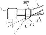
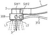
상기 조사부는 상기 진료구 또는 상기 진료구의 장착부의 근방에 설치되고, 상기 여기광이 상기 진료구를 둘러싸는 주변 부위로부터 상기 이변부를 향하여 조사된다.The irradiation section is provided in the vicinity of the treatment chamber or the mounting portion of the treatment chamber, and the excitation light is irradiated toward the side region from the peripheral portion surrounding the treatment chamber.
상기 광원은 상기 선단부와는 별체(別體)로 형성된 별체 부재에 설치되고, 상기 별체 부재는 상기 선단부와 착탈이 자유롭게 계합할 수 있고, 상기 선단부와 계합되었을 때, 상기 광원에 급전하는 접속 부재를 가진다.The light source is provided in a separate member formed separately from the distal end, and the separate member is freely engaged with the distal end, and when connected with the distal end, connects the connecting member to feed the light source. Have
치료용 레이저광을 조사하는 상기 진료구가 상기 선단부에 구비되고, 상기 광 조사 수단의 광원이 상기 선단부에 배치되고, 또한 상기 광 조사 수단은 상기 여기광과 상기 치료용 레이저광을 시분할로 상기 이변부에 조사한다.The treatment tool for irradiating a treatment laser light is provided at the distal end portion, a light source of the light irradiating means is disposed at the distal end portion, and the light irradiating means time-divisions the excitation light and the treatment laser light at the two sides. Investigate the department.
상기 조사부는 상기 인스트루먼트의 선단부에 착탈이 자유롭게 장착할 수 있는 장착 부재가 있는 어댑터에 구비되고, 상기 광원은 복수의 발광소자를 포함하고, 상기 복수의 발광소자가 상기 어댑터의 단면부에 병설되어 있다.The irradiation section is provided in an adapter having a mounting member that can be detachably attached to the distal end of the instrument. The light source includes a plurality of light emitting elements, and the plurality of light emitting elements are arranged in a cross section of the adapter. .
상기 어댑터는 상기 인스트루먼트의 선단부에 착탈이 자유롭게 끼워지는 링 형상을 가지고, 상기 광원을 구동 조작하는 조작부를 구비하고, 또한 상기 광원을 구동하는 전원을 구비하고, 상기 전원은 일차전지 또는 이차전지이다.The adapter has a ring shape to be detachably attached to the distal end of the instrument, includes an operation unit for driving and operating the light source, and further includes a power source for driving the light source, wherein the power source is a primary battery or a secondary battery.
상기 광원을 구동하는 전원은 상기 어댑터와 분리하여 설치되고, 또한 상기 전원은 상기 인스트루먼트의 본체에 착탈이 자유롭게 설치된다.The power source for driving the light source is installed separately from the adapter, and the power source is detachably attached to the main body of the instrument.
상기 광원을 구동 조작하는 조작부가 상기 인스트루먼트의 본체에 착탈이 자유롭게 장착되는 것으로 하고, 상기 장착 부재는 상기 어댑터를 상기 인스트루먼트의 선단부에 탄성적으로 유지하는 것으로 하였다.It is assumed that the operation unit for driving the light source is detachably attached to the main body of the instrument, and the mounting member elastically holds the adapter at the tip of the instrument.
상기 어댑터는 상기 인스트루먼트의 본체의 축방향과 직교하고, 상기 본체의 주변으로 퍼지는 평면을 가지는 필터판을 구비하고 있다.The adapter is provided with a filter plate having a plane orthogonal to the axial direction of the main body of the instrument and spreading around the main body.
상기 어댑터는 상기 구강 내를 조명하는 조명 수단이 상기 인스트루먼트에 설치되어 있는 경우, 상기 조명 수단으로부터의 조명광을 차단하는 위치에 설치된다.The adapter is installed at a position that blocks the illumination light from the illumination means when the illumination means for illuminating the oral cavity is provided in the instrument.
상기 인스트루먼트가 치료용 레이저광과 상기 치료용 레이저광의 조사 위치를 조준하는 가이드 광을 상기 구강 내에 조사할 수 있는 레이저 핸드피스이며, 상기 여기광이 상기 가이드광에 포함되는 것으로 하였다.Said instrument is a laser handpiece which can irradiate a therapeutic laser beam and guide light which aims at the irradiation position of said therapeutic laser light in the oral cavity, and the excitation light is included in the guide light.
상기 조사부는 상기 진료구의 장착부 근방에 배치된 상기 발광소자를 가지고, 상기 발광소자가 상기 진료구를 둘러싸는 형태로 배치되고, 또한 상기 발광소자가 상기 진료구의 장착부 근방에 수납되어 있다.The irradiation section has the light emitting element arranged near the mounting portion of the medical treatment chamber, the light emitting element is arranged in a form surrounding the medical treatment instrument, and the light emitting element is housed near the mounting portion of the medical treatment instrument.
상기 광 조사 수단이 파장이 다른 광을 방출하는 복수의 광원을 가지고, 상기 복수의 광원을 절환하여 선택할 수 있고, 또는 적어도 하나의 광원에 관한 방출 광량을 가변 조절할 수 있는 조작부가 상기 인스트루먼트에 설치된다.The light irradiation means has a plurality of light sources that emit light having different wavelengths, and an operation unit capable of switching and selecting the plurality of light sources, or variablely adjusting the amount of emitted light with respect to at least one light source, is provided in the instrument. .
발명의 효과Effects of the Invention
이상의 구성에 의한 발명에 의하면, 치과 진료 장치의 진료구의 근방에 이변부를 특징적으로 추출하는 광을 대상 부위에 방사하는 광원을 포함한 광 조사 수단을 구비하고 있으므로, 치료 작업자는 이 치과 진료 장치를 가지고 진료하는 경우, 방사된 광에 의하여 여기되어 발생하는 형광 또는 반사광을 검출하는 필터 등을 사용하여, 육안으로 구강 내의 이변부, 예를 들면, 우식 부위, 연화 치아의 주체가 되는 조직부, 치석, 치구, 바이오 필름, 결손, 금 등을 보다 명료하게 관찰할 수 있게 되어, 진료 작업 중에도 진료 범위나 진료 정도를 확인할 수 있다.According to the invention by the above-mentioned structure, since the light irradiation means which includes the light source which emits the light which characteristically extracts a side part in the vicinity of the medical examination of the dental examination apparatus to a target site | part is provided, the treatment worker treats with this dental examination apparatus In this case, using a filter that detects fluorescence or reflected light generated by being excited by the emitted light, the peripheral part of the oral cavity, for example, a caries part, a tissue part which is the subject of softened teeth, tartar, jig, Biofilms, defects, gold, etc. can be observed more clearly, so that you can check the scope of care and the degree of care even during the treatment work.
또한, 복수 파장의 발광소자나 백색광원 등의 조명용 광원을 조합함으로써, 복수 종류의 환부 추출 기능을 시분할 또는 수동으로 절환하여 사용하거나 조명용으로서 사용할 수도 있다. 이로써, 환부의 종류나 치료 목적에 따라 핸드피스나 진료 기구를 교체할 필요가 없어 작업 효율이 올라간다.Further, by combining a light source for illumination such as a light emitting element having a plurality of wavelengths, a white light source, or the like, a plurality of kinds of affected part extraction functions can be used for time division or manual switching, or for illumination. As a result, there is no need to replace the handpiece or the medical device according to the type of the affected part or the treatment purpose, thereby increasing work efficiency.
또한, 치과 진료 장치의 진료구의 근방에, 대상 부위를 조명하는 광 조사 수단을 병용할 수 있으므로, 진료 작업자는 조명 장치와 진료 장치를 바꾸어가면서, 진료 작업을 진행시킬 수 있게 되어 작업 효율이 향상된다.In addition, since the light irradiation means for illuminating the target site can be used in the vicinity of the treatment ward of the dental treatment apparatus, the treatment worker can advance the treatment work while changing the lighting apparatus and the treatment apparatus, thereby improving work efficiency. .
이상과 같이, 본 발명에 의하면 기존의 조명 기능을 가지는 핸드피스에 본 발명의 구강 내 조명 장치를 설치하는 경우, 구강 내의 조명 기능에 부가하여, 구강 내의 이변부를 추출할 수 있는 기능을 간단하게 구비할 수 있게 되고, 또한 조명 기능이 없는 치과용 핸드피스에 본 발명의 구강 내 조명 장치를 장착하는 경우, 이와 같은 구강 내의 이변부를 추출할 수 있는 기능을 구비한 핸드피스로 용이하게 변경할 수 있고, 또한 통상의 조명 기능을 부가하면, 진료대에 부속되어 있는 무영등보다, 구강 내의 이변부 뿐만 아니라, 이변부 주변의 생체 조직을 관찰하기 쉬워서 치료가 용이하게 된다.As described above, according to the present invention, in the case of installing the intraoral illumination device of the present invention on a handpiece having an existing illumination function, in addition to the illumination function in the oral cavity, it is simply provided with the function of extracting the extraordinary part in the oral cavity. When the intraoral illumination device of the present invention is attached to a dental handpiece without a lighting function, it can be easily changed to a handpiece having a function for extracting the extraordinary part in the oral cavity, In addition, when a normal lighting function is added, it is easier to observe not only the marginal part in the oral cavity, but also the living tissue surrounding the marginal part, rather than the shadowless lamp attached to the treatment table, thereby making the treatment easier.
또한, 전술한 바와 같이, 이변부를 추출하는 여기광을 방사하는 기능을 가지고 있지 않은 각종 치과용 핸드피스에, 본 발명의 구강 내 조명 장치를 장착하고 여기광을 조사함으로써, 구강 내의 이변부에서 여기된 형광을 관찰하면서 이변부의 분포 상황을 기초로 하여 진료 또는 치료를 실시할 수 있으므로, 이변부가 치료하여야 할 부위라는 것을 면 형태의 화상 정보로서 명확하게 인식할 수 있어, 환부만을 선택적으로 치료할 수 있다.In addition, as described above, by mounting the intraoral illumination device of the present invention and irradiating the excitation light to various dental handpieces which do not have a function of emitting excitation light for extracting the excursion part, excitation is performed at the concave part in the oral cavity. Since fluorescence is observed, treatment or treatment can be performed based on the distribution status of the marginal region, so that the marginal region can be clearly recognized as image information in the form of a plane, and only the lesion can be selectively treated. .
또한, 구강 내를 조명하는 조명광과 우식 등의 이변부를 추출할 수 있는 여기광 두 가지 모두를 동시에 조사할 수 있는 기능이 구비되므로, 우식 등의 이변부뿐만 아니라 이변부 주변의 정상적인 생체 조직도 동시에 선명하게 시인할 수 있으므로, 핸드피스의 편리성이 향상되고, 진료 또는 치료를 확실하고, 또한 효율적으로 실시할 수 있다.In addition, since the illumination light illuminating the oral cavity and the excitation light for extracting the extraordinary part such as caries are simultaneously provided, not only the extraordinary part such as the caries but also the normal biological tissue around the extraordinary part are simultaneously cleared. Since it can be visually recognized, the convenience of a handpiece can be improved and medical treatment or a treatment can be reliably and efficiently performed.
본 발명에 의한 구강 내 조명 장치는 상기 이변부를 추출하는 파장 및/또는 상기 이변부를 조명하는 파장의 광으로서 백색광, 단색광, 적외광 및 자외광 중 어느 하나 이상의 광을 조사할 수 있으므로, 여러 가지 이변부에 대응하는 최적의 여기광이나 조명광을 병용할 수 있다. 또한, 상기 광원으로부터 방사되는 상기 광의 강도가 조정되도록 되어 있으므로, 여기광이나 조명광을 이변부를 시인하기 쉬운 광량으로 조정할 수 있다.The intraoral illumination device according to the present invention can irradiate any one or more of white light, monochromatic light, infrared light, and ultraviolet light as light having a wavelength for extracting the two-sided portion and / or a wavelength for illuminating the two-sided portion. The most suitable excitation light and illumination light corresponding to a negative part can be used together. In addition, since the intensity of the light emitted from the light source is adjusted, the excitation light and the illumination light can be adjusted to the amount of light that is easy to see the two-sided portion.
본 발명에 의하면, 상기 광원은 발광 다이오드 또는 반도체 레이저의 발광소자로 이루어지므로 제품을 소형화하기 쉽고, 시판품을 입수할 수 있으므로, 비용이 적게 드는 제품으로 할 수 있다. 또한, 상기 광원은 할로겐 램프, 크세논 램프, 나트륨 램프, 메탈 할라이드 램프 또는 수은 램프 중 어느 하나의 램프를 포함하므로, 상기 램프로부터 방사되는 폭 넓은 파장을 가지기 때문에, 조명광으로서도 사용할 수 있다. 또한, 상기 램프로부터 방사되는 폭 넓은 파장의 광으로부터, 이변부를 추출하는 특정 파장을 선택하여 방사하도록 광학 필터를 구비함으로써, 여러 가지 파장의 여기광을 발생할 수 있다. 또한, 이러한 광학 필터를 착탈이 자유롭게 하여 두면, 램프 광원의 광을 조명광으로서도 여기광의 광으로서도 사용할 수 있다.According to the present invention, since the light source is made of a light emitting element of a light emitting diode or a semiconductor laser, it is easy to miniaturize a product and a commercially available product can be obtained. In addition, since the light source includes any one of halogen lamps, xenon lamps, sodium lamps, metal halide lamps or mercury lamps, the light source can be used as illumination light because it has a broad wavelength emitted from the lamp. In addition, by providing an optical filter to select and radiate a specific wavelength for extracting a side portion from the light having a broad wavelength emitted from the lamp, excitation light having various wavelengths can be generated. In addition, when such an optical filter is detachably attached, the light of the lamp light source can be used as the illumination light or the excitation light.
또한, 상기 이변부를 추출하는 파장은 405±50 nm의 근자외선 영역, 470±30 nm의 청색 영역, 700±100 nm의 적색 영역, 적외선 영역, 또는 근적외선 영역이므로, 치석이나 우식, 충전물의 유무, 세세한 균열 등을 식별할 수 있다. 상기 광원으로부터 방사되는 광은 광중합 수지의 경화에 적합한 파장의 광을 포함하므로, 우식이나 균열 부분에 대하여 바로 광중합 수지를 충전하는 치료를 실시할 수 있다.In addition, the wavelength of extracting the two-sided portion is near-ultraviolet region of 405 ± 50 nm, blue region of 470 ± 30 nm, red region of 700 ± 100 nm, infrared region, or near infrared region, the presence or absence of tartar, caries, filler, Fine cracks can be identified. Since the light emitted from the light source includes light having a wavelength suitable for curing the photopolymerized resin, treatment for filling the photopolymerized resin directly to the caries or cracks can be performed.
본 발명에 의하면, 상기 광원은 복수의 파장의 광을 방사할 수 있고, 상기 광원으로부터 방사되는 광의 파장을 절환하여 조사할 수 있으므로, 예를 들면, 주지의 파장으로 절환 가능한 발광 다이오드나 반도체 레이저를 사용할 수 있기 때문에, 복수의 여기광을 선택하여 사용할 수 있다.According to the present invention, since the light source can emit light of a plurality of wavelengths, and can be irradiated by switching the wavelength of light emitted from the light source, for example, a light emitting diode or a semiconductor laser that can be switched to a known wavelength can be used. Since it can be used, several excitation light can be selected and used.
본 발명의 구강 내 조명 장치에서는 복수의 파장을 방사할 수 있는 발광소자를 구비하고, 이 발광소자의 구동을 절환되도록 하고, 파장 선택을 가능하게 하였으므로, 예를 들면, 조명 기능과 이변부 추출 기능의 역할을 기존의 핸드피스에 부가할 수 있어서, 이변부 추출 기능이 있는 복수의 파장을 변경할 수 있다. 이것에 의하여, 치아의 우식 치료 중에 있어서, 조명 기능과 이변부 추출 기능을 모두 구사하면서, 우식으로부터 발광되는 형광이 없어질 때까지 제거하면 되기 때문에, 환부의 제거에 대한 기준을 얻을 수 있다. 또한, 우식과 치석 등, 다른 이변부에 각각 최적의 여기광의 파장을 선택 사용함으로써 시인성이 높아진다.The intraoral illumination device of the present invention includes a light emitting element capable of emitting a plurality of wavelengths, switches the driving of the light emitting element, and enables the wavelength selection, for example, an illumination function and a two-sided extraction function. The role of can be added to the existing handpiece, so that a plurality of wavelengths having a side-side extraction function can be changed. Thereby, in the treatment of caries of a tooth, it is necessary to remove both the illumination function and the lateral extraction function while removing until the fluorescence emitted from the caries disappears, thereby obtaining a standard for removing the affected part. Moreover, visibility is improved by selecting and using the optimal wavelength of excitation light, respectively, in the other side parts, such as caries and calculus.
또한, 본 발명에 의하면, 상기 광원이 상기 램프를 포함하는 경우에, 상기 램프로부터 방사되는 광으로부터, 다른 파장의 광이 광학 필터의 교환에 의하여 선택되므로, 광학 필터의 교환에 의하여, 조명 기능과 이변부 추출 기능을 겸비하게 하여, 다른 이변부에 대하여 최적의 이변부 추출 기능을 하도록 할 수 있다.Further, according to the present invention, when the light source includes the lamp, since light of a different wavelength is selected from the light emitted from the lamp by replacing the optical filter, the lighting function and By combining the two-sided extraction function, it is possible to perform the optimum two-sided extraction function for the other side.
본 발명에 의하면, 상기 광원은 복수의 발광소자를 포함하고, 상기 복수의 발광소자가 상기 어댑터의 단부에 있어서 병설되어 있으므로, 효율 좋은 방사를 실시할 수 있다. 상기 어댑터는 치과용 인스트루먼트의 선단부에 착탈이 자유롭게 끼워지는 링 형상을 하고 있기 때문에, 어느 각도로부터도 방사할 수 있으므로, 그림자가 생기지 않고, 치과용 인스트루먼트를 사용할 수 있다. 또한, 상기 광원에 포함되는 복수의 발광소자가 상기 어댑터의 단부에 대하여 환상으로 배치되어 있으므로, 그림자가 생기지 않고 치과용 인스트루먼트를 사용할 수 있다.According to the present invention, since the light source includes a plurality of light emitting elements, and the plurality of light emitting elements are arranged at the ends of the adapter, efficient radiation can be performed. Since the adapter has a ring shape to be detachably attached to the distal end of the dental instrument, the adapter can be radiated from any angle, so that no shadow is generated and the dental instrument can be used. In addition, since a plurality of light emitting elements included in the light source are arranged in an annular shape with respect to the end of the adapter, a dental instrument can be used without a shadow.
또한, 본 발명에 의하면, 상기 광원을 구동 조작하는 조작부가 상기 어댑터에 설치되어 있으므로, 어댑터에 설치되어 있는 스위치 등을 조작하는 것만으로, 광원의 온·오프 등의 조작을 실시할 수 있다. 또한, 상기 전원은 상기 어댑터에 설치되어 있으므로, 전원을 버튼 전지 등의 소형의 것을 사용하면, 장치를 전체적으로 소형화할 수 있다. 상기 전원은 일차전지 또는 이차전지이므로, 간단하게 착탈 교환하여 사용할 수 있다.Further, according to the present invention, since the operation unit for driving the light source is provided in the adapter, the operation such as turning on and off the light source can be performed only by operating a switch or the like provided in the adapter. In addition, since the power supply is provided in the adapter, when a small power source such as a button battery is used, the device can be miniaturized as a whole. Since the said power supply is a primary battery or a secondary battery, it can be used simply detachably replacing.
본 발명에 의하면, 상기 광원은 상기 어댑터와는 분리되어 설치된 전원에 의하여 구동되고, 크고 무거운 전원을 광원으로부터 분리해둘 수 있기 때문에, 인스트루먼트의 조작에 지장이 없게 할 수 있다.According to the present invention, since the light source is driven by a power source installed separately from the adapter, and the large and heavy power source can be separated from the light source, operation of the instrument can be prevented.
이상과 같이, 본 발명의 구강 내 조명 장치에는 전원이 어댑터에 내장되고, 또는 어댑터에 접속되어 있으므로, 기존의 인스트루먼트에 전원이 구비되어 있지 않아도, 어댑터에 구비된 발광소자를 점등 구동할 수 있어, 조명 기능 또는 이변부 추출 기능을 달성할 수 있다. 한편, 기존의 인스트루먼트에 전력이 공급되는 구성으로 되어 있는 경우에도, 구강 내 조명 장치용으로 전력 공급의 접속 구성을 특별히 구비할 필요가 없고, 비용이 올라가는 경우가 없다.As described above, since the power supply is built in the adapter or connected to the adapter, the light emitting element included in the adapter can be lighted and driven, as described above. Illumination or two-sided extraction can be achieved. On the other hand, even when the power supply is provided to an existing instrument, it is not necessary to particularly provide a connection configuration of power supply for the intraoral lighting device, and the cost does not increase.
본 발명에 의하면, 상기 전원은 치과용 인스트루먼트의 본체에 착탈이 자유롭게 설치되므로, 본체에 설치하지 않는 경우에 비하여 복잡하지 않고, 전원의 교환이 쉬워진다. 또한, 상기 광원을 구동 조작하는 조작부가 치과용 인스트루먼트의 본체에 착탈이 자유롭게 설치되므로 조작성이 좋아진다.According to the present invention, since the power supply is detachably attached to the main body of the dental instrument, the power supply is not as complicated as the case where the power supply is detached from the main body, and the power supply can be easily replaced. In addition, since the operation unit for driving the light source is detachably attached to the main body of the dental instrument, the operability is improved.
또한, 본 발명에 의하면, 상기 장착 부재가 상기 어댑터를 치과용 인스트루먼트의 본체에 탄성적으로 유지되므로, 착탈이 용이하게 된다. 또한, 본 발명의 구강 내 조명 장치에서는 각종 핸드피스에 설치하기 위한 장착 부재가 전용 형상이 아니라, 코일 등으로 탄성적으로 유지할 수 있도록 하였으므로, 절삭용 핸드피스, 예를 들면, 에어 터빈 핸드피스, 마이크로 모터 핸드피스, 스케일러 핸드피스 등, 모든 종류의 핸드피스에 있어서의 선단부에 사용할 수 있게 되어, 염가의 핸드피스 시스템을 구성할 수 있다.Further, according to the present invention, since the mounting member elastically holds the adapter to the main body of the dental instrument, the attachment and detachment is facilitated. In addition, in the intraoral lighting apparatus of the present invention, the mounting member for mounting to various handpieces is not a dedicated shape, but can be elastically held by a coil or the like. Therefore, a cutting handpiece, for example, an air turbine handpiece, It can be used at the front end of all kinds of handpieces, such as a micromotor handpiece and a scaler handpiece, and can form an inexpensive handpiece system.
본 발명에 의하면, 상기 어댑터에는 떨어져 있는 광원으로부터 방사된 광이 도광부재에 의하여 도광되기 때문에, 광원과 도광부재의 출사단과의 거리를 둘 수 있어서 인스트루먼트의 조작성을 좋게 하고, 시야를 확보하기 쉬운 구성으로 할 수 있다.According to the present invention, since the light emitted from the light source away from the light guide is guided by the light guiding member, the distance between the light source and the exit end of the light guiding member can be set to improve the operability of the instrument and to secure the field of view. You can do
본 발명에 의하면, 상기 어댑터는 치과용 인스트루먼트 본체의 축방향과 직교하는 평면을 가지는 필터판을 구비할 수 있으므로, 시술자는 상기 필터판을 투과한 형광만을 관찰함으로써, 이변부를 시인하기 쉬워진다. 이와 같이, 본 발명의 구강 내 조명 장치에는 여기광만을 제거하고, 또는 형광을 통과시키는 필터판을 조합하는 것이 가능하므로, 종래와 같이 그러한 필터 기능이 있는 안경 또는 고글을 사용하지 않아도 되고, 특히 복수의 파장을 선택하여 사용하는 경우에는 염가의 필터판을 그 파장에 맞추어 준비하면 된다.According to the present invention, since the adapter can include a filter plate having a plane orthogonal to the axial direction of the dental instrument body, the operator can easily visualize the two-sided part by observing only the fluorescence transmitted through the filter plate. In this way, the intraoral illumination device of the present invention can be combined with a filter plate that removes only excitation light or allows fluorescence to pass, so that it is not necessary to use glasses or goggles having such a filter function as in the prior art, and in particular, a plurality of What is necessary is just to prepare a cheap filter board according to the wavelength, when selecting and using the wavelength.
또한, 본 발명에 의하면, 치과용 인스트루먼트가 상기 이변부를 조명하는 조명 수단을 구비하고 있는 경우, 상기 어댑터는 상기 조명수단으로부터의 조명광을 차단하는 위치, 즉, 기존의 조명 광 조사 기능부 핸드피스에 있어서, 조사광이 조사되는 조사단에 설치되므로, 시술자는 기존의 조명광의 조사 각도나 위치와 그다지 변화되지 않는 상태로 사용할 수 있다.In addition, according to the present invention, when the dental instrument is provided with lighting means for illuminating the side portion, the adapter is located at a position to block the illumination light from the lighting means, that is, the existing illumination light irradiation function handpiece In this case, since the irradiation light is provided to the irradiation stage to be irradiated, the operator can use it in a state that does not change so much with the irradiation angle or position of the existing illumination light.
본 발명에 의하면, 치과용 인스트루먼트가 치과용 에어 터빈 핸드피스, 치과용 마이크로 모터 핸드피스, 치과용 스케일러 핸드피스, 치과용 쓰리 웨이 실린지, 덴탈 미러 버큠 실린지, 치과용 광중합 조사기, 레이저 핸드피스, 치과용 치면 청소기 중 어느 하나이므로, 어느 인스트루먼트에 있어서도, 이변부를 간단하게 추출할 수 있다.According to the present invention, the dental instrument is a dental air turbine handpiece, dental micromotor handpiece, dental scaler handpiece, dental three-way syringe, dental mirror vacuum syringe, dental light polymerization irradiator, laser handpiece Since the dental tooth cleaner is any one of the dental tooth cleaners, the two-sided portion can be easily extracted in any instrument.
예를 들면, 조사하는 여기광으로서 예를 들면, 400 nm 부근의 파장의 광을 채용하고 있으므로, 우식 부위, 치석, 치구로부터 특징적인 형광을 효율적으로 여기시킬 수 있다.For example, as the excitation light to be irradiated, for example, light having a wavelength of around 400 nm is employed, so that characteristic fluorescence can be efficiently excited from the caries site, calculus and jig.
이들 환부의 제거를 목적으로 하는 치과용 에어 터빈 핸드피스, 치과용 마이크로 모터 핸드피스, 치료용 스케일러 핸드피스, 레이저 핸드피스, 치과용 치면 청소기 등의 조명용으로서 최적이 된다. 이 400 nm 부근의 파장은 LED나, LD를 포함한 반도체 레이저 등에 의하여 간단하게 얻을 수 있다. 특히, 파장이 405 nm인 광은 DVD용의 반도체 소자에 의하여 얻을 수 있다. 또한, 레이저 핸드피스의 경우에는 여기광이나 조명광을 가이드 빔으로서 사용할 수 있다.It is optimal for illumination of dental air turbine handpieces, dental micromotor handpieces, therapeutic scaler handpieces, laser handpieces, dental tooth cleaners and the like for the purpose of removing these lesions. The wavelength around 400 nm can be easily obtained by LED, semiconductor laser containing LD, or the like. In particular, light having a wavelength of 405 nm can be obtained by a semiconductor element for DVD. In the case of a laser handpiece, excitation light or illumination light can be used as the guide beam.
또한, 예를 들면, 에어 터빈 핸드피스 전용, 스케일러 핸드피스 전용의 형상의 구강 내 조명 장치를 채용하면, 각각의 핸드피스용 어댑터 광원 하나를 사용할 때 마다 장착하면 되기 때문에, 각각에 대하여 조명이 부착된 핸드피스를 구비하는 것 보다는, 조명 기능이 없는 핸드피스와 본 발명의 구강 내 조명 장치의 하나를 준비하는 것이 저렴하다.For example, if an intraoral lighting device having a shape dedicated to an air turbine handpiece or a scaler handpiece is employed, it is only necessary to attach it each time one adapter light source for each handpiece is used. Rather than having a handpiece provided, it is cheaper to prepare one of the handpiece without the illumination function and the intraoral illumination device of the present invention.
본 발명의 구강 내 조명 장치는 또한, 치과용 쓰리 웨이 실린지나 버큠 실린지에 탑재되는 것이 가능하게 되므로, 치과의가 절삭용 인스트루먼트로 치아를 치료하고 있을 때, 절삭용 인스트루먼트의 조작성을 악화시키지 않으면서, 치아의 환부를 명시하는 것이 가능해진다. 이것은 통상, 치과용 쓰리 웨이 실린지나 버큠 실린지는 위생사가 사용하는 인스트루먼트이고, 치과용 쓰리 웨이 실린지가 치료 부위에 물이나 공기를 뿌리고, 버큠 실린지가 치료 부위로부터의 물이나 절삭분 등을 흡입하면서, 함께 치료 부위의 방향을 향하고 있기 때문이다. 이들 인스트루먼트에 여기 광원을 설치하면, 치과의가 사용하는 절삭용 인스트루먼트에 일부러 여기용 광원을 장비하지 않아도 되므로, 그 조작성을 악화시키지 않는다.Since the intraoral illumination device of the present invention can also be mounted on a dental three-way syringe or a vacuum syringe, when the dentist is treating a tooth with a cutting instrument, the operability of the cutting instrument is not deteriorated. It becomes possible to specify the affected part of the tooth. This is usually an instrument used by a hygienist for dental three-way syringes and vacuum syringes, while dental three-way syringes spray water or air onto the treatment site, and the vacuum syringe inhales water or cutting powder from the treatment site, This is because they are facing the treatment site together. When an excitation light source is provided in these instruments, the excitation light source does not need to be provided intentionally in the cutting instrument used by a dentist, and it does not deteriorate the operability.
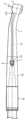
도 1A 및 1B는 본 발명을 에어 터빈 핸드피스에 적용한 실시예 1에 의한 개략 구성을 설명하는 도면이다.1A and 1B are views for explaining a schematic configuration according to
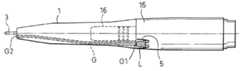
도 2는 실시예 1에 의한 핸드피스 선단부에 있어서의 광 조사 수단의 설치에 관한 구체예 1을 설명하는 도면이다.It is a figure explaining the specific example 1 regarding installation of the light irradiation means in the front-end | tip of the handpiece which concerns on Example 1. FIG.
도 3은 실시예 1에 의한 핸드피스 선단부에 있어서의 광 조사 수단의 설치에 관한 구체예 2를 설명하는 도면이다.FIG. 3 is a view for explaining a specific example 2 of the installation of the light irradiation means at the tip of the handpiece according to the first embodiment. FIG.
도 4A 및 도4B는 실시예 1에 의한 핸드피스 선단부에 있어서의 광 조사 수단의 설치에 관한 구체예 3을 설명하는 도면이다.4A and 4B are views for explaining a specific example 3 relating to the installation of the light irradiation means at the tip of the handpiece according to the first embodiment.
도 5는 실시예 1에 의한 핸드피스 선단부에 있어서의 광 조사 수단의 설치에 관한 구체예 4를 설명하는 도면이다.5 is a view for explaining a specific example 4 of the installation of the light irradiation means at the tip of the handpiece according to the first embodiment.
도 6A 및 도6B는 실시예 1에 의한 핸드피스 선단부에 있어서의 광 조사 수단의 설치에 관한 구체예 5를 설명하는 도면이다.6A and 6B are views for explaining a specific example 5 of the installation of the light irradiation means at the tip of the handpiece according to the first embodiment.
도 7은 구체예 5에 있어서의 광 조사 수단의 광원부의 상세를 설명하는 사시도이다.It is a perspective view explaining the detail of the light source part of the light irradiation means in the specific example 5. FIG.
도 8A 및 도8B는 실시예 1에 의한 핸드피스 선단부에 있어서의 광 조사 수단의 설치에 관한 구체예 6을 설명하는 도면이다.8A and 8B are views for explaining a specific example 6 of the installation of the light irradiation means at the tip of the handpiece according to the first embodiment.
도 9A 및 9 B는 실시예 1에 의한 핸드피스 선단부에 있어서의 광 조사 수단의 설치에 관한 구체예 7을 설명하는 도면이다.9A and 9B are views for explaining a specific example 7 of the installation of the light irradiation means at the tip of the handpiece according to the first embodiment.
도 10은 실시예 1에 의한 핸드피스 선단부에 있어서의 광 조사 수단의 설치에 관한 구체예 8을 설명하는 도면이다.10 is a view for explaining a specific example 8 of the installation of the light irradiation means at the tip of the handpiece according to the first embodiment.
도 11은 구체예 8에 있어서의 광 조사 수단의 광원부의 상세를 설명하는 도면이다.It is a figure explaining the detail of the light source part of the light irradiation means in the specific example 8. FIG.
도 12는 실시예 1에 의한 광 조사 수단의 설치에 관한 구체예 9를 설명하는 도면이다.12 is a view for explaining a specific example 9 of the installation of the light irradiation means according to the first embodiment.
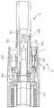
도 13은 본 발명을 마이크로 모터 핸드피스에 적용한 실시예 2에 의한 핸드피스 선단부에 있어서의 광 조사 수단의 설치에 관한 구체예 10를 설명하는 도면이다.It is a figure explaining the specific example 10 regarding installation of the light irradiation means in the front-end | tip part of the handpiece by Example 2 which applied this invention to the micromotor handpiece.
도 14는 실시예 2에 의한 핸드피스 선단부에 있어서의 광 조사 수단의 설치 에 관한 구체예 11을 설명하는 도면이다.FIG. 14 is a view for explaining a specific example 11 relating to the installation of the light irradiation means at the tip of the handpiece according to the second embodiment.
도 15는 구체예 11에 있어서의 광 조사 수단의 광원부의 상세를 설명하는 도면이다.It is a figure explaining the detail of the light source part of the light irradiation means in Specific Example 11. FIG.
도 16A 및 도 16B는 실시예 1에 의한 핸드피스 선단부에 있어서의 광 조사 수단의 설치에 관한 구체예 12와 그 변형예를 설명하는 도면이다.16A and 16B are views for explaining a specific example 12 and modifications thereof regarding the installation of the light irradiation means at the tip of the handpiece according to the first embodiment.
도 17A 및 도 17B는 본 발명을 스케일러 핸드피스에 적용한 실시예 3에 의한 개략 구성을 설명하는 도면이다.17A and 17B are views for explaining a schematic configuration according to
도 18A 및 도 18B는 실시예 3에 의한 핸드피스 선단부에 있어서의 광 조사 수단의 설치에 관한 구체예 13을 설명하는 도면이다.18A and 18B are views for explaining a specific example 13 of the installation of the light irradiation means at the tip of the handpiece according to the third embodiment.
도 19는 실시예 3에 의한 핸드피스 선단부에 있어서의 광 조사 수단의 설치에 관한 구체예 14를 설명하는 도면이다.FIG. 19 is a view for explaining a specific example 14 of the installation of the light irradiation means at the tip of the handpiece according to the third embodiment. FIG.
도 20A 및 도 20B는 실시예 3에 의한 핸드피스 선단부에 있어서 광 조사 수단의 설치에 관한 구체예 15를 설명하는 도면이다.20A and 20B are views for explaining a specific example 15 regarding the installation of the light irradiation means at the tip of the handpiece according to the third embodiment.
도 21는 실시예 3에 의한 핸드피스 선단부에 있어서의 광 조사 수단의 설치에 관한 구체예 16을 설명하는 도면이다.FIG. 21 is a view for explaining a specific example 16 of the installation of the light irradiation means at the tip of the handpiece according to the third embodiment. FIG.
도 22는 본 발명을 쓰리 웨이 실린지에 적용한 실시예 4에 의한 광 조사 수단의 설치에 관한 구체예 l7를 설명하는 도면이다.It is a figure explaining the specific example l7 regarding installation of the light irradiation means by Example 4 which applied this invention to a three way syringe.
도 23은 실시예 4에 의한 핸드피스 선단부에 있어서의 광 조사 수단의 설치에 관한 구체예 18를 설명하는 도면이다.FIG. 23 is a view for explaining a specific example 18 of the installation of the light irradiation means in the tip of the handpiece according to the fourth embodiment. FIG.
도 24는 본 발명을 라이트 프로브에 적용한 실시예 5에 의한 광 조사 수단의 설치에 관한 구체예 19를 설명하는 도면이다.It is a figure explaining the specific example 19 which concerns on installation of the light irradiation means by Example 5 which applied this invention to the light probe.
도 25는 실시예 5에 의한 핸드피스 선단부에 있어서의 광 조사 수단의 설치에 관한 구체예 20을 설명하는 도면이다.FIG. 25 is a view for explaining a specific example 20 of the installation of the light irradiation means at the tip of the handpiece according to the fifth embodiment. FIG.
도 26은 본 발명을 덴탈 미러에 적용한 실시예 6에 의한 광 조사 수단의 설치에 관한 구성을 설명하는 도면이다.It is a figure explaining the structure regarding installation of the light irradiation means by Example 6 which applied this invention to the dental mirror.
도 27A 및 도 27B는 본 발명을 치과용 광중합기에 적용한 실시예 7에 의한 광 조사 수단의 설치에 관한 구성을 설명하는 도면이다.27A and 27B are views for explaining the configuration of the installation of the light irradiation means according to the seventh embodiment to which the present invention is applied to a dental photopolymerizer.
도 28A 및 도 28B는 본 발명을 덴탈 레이저 치료기에 적용한 실시예 8에 의한 광 조사 수단의 설치에 관한 구체예 21을 설명하는 도면이다.28A and 28B are views for explaining a specific example 21 of the installation of the light irradiation means according to the eighth embodiment to which the present invention is applied to a dental laser treatment machine.
도 29는 본 발명이 적용된 레이저 핸드피스를 사용하여 진료하고 있는 모습을 설명하는 도면이다.29 is a view for explaining the state of the doctor using the laser handpiece to which the present invention is applied.
도 30은 본 발명을 레이저 핸드피스에 적용한 실시예 8에 의한 광 조사 수단의 설치에 관한 구체예 22를 설명하는 도면이다.30 is a view for explaining a specific example 22 relating to the installation of the light irradiation means according to the eighth embodiment to which the present invention is applied to a laser handpiece.
도 31은 본 발명을 레이저 핸드피스에 적용한 실시예 8에 의한 광 조사 수단의 설치에 관한 구체예 23을 설명하는 도이다.FIG. 31 is a view for explaining a specific example 23 of the installation of the light irradiation means according to the eighth embodiment to which the present invention is applied to a laser handpiece. FIG.
도 32A 내지 도 32C는 본 발명을 레이저 핸드피스에 적용한 실시예 8에 의한 광 조사 수단의 설치에 관한 구체예 24를 설명하는 도면이다.32A to 32C are views for explaining a specific example 24 of the installation of the light irradiation means according to the eighth embodiment to which the present invention is applied to a laser handpiece.
도 33A 및 도 33B는 본 발명에 의한 전원 일체형의 구강 내 조명 장치와 관련되는 실시예 9에 대하여, 핸드피스 본체에 설치한 경우의 구체예 25를 설명하는 도면이다.33A and 33B are views for explaining a specific example 25 in the case where the handpiece body is installed in the ninth embodiment related to the intraoral lighting device of a power source integrated body according to the present invention.
도 34A 및 도 34B는 실시예 9의 구강 내 조명 장치를 핸드피스 헤드에 설치한 경우를 나타내는 구체예 26을 설명하는 도면이다.34A and 34B are views for explaining a specific example 26 showing the case where the intraoral illumination device of Example 9 is installed on the handpiece head.
도 35A 내지 도 35C는 구체예 26에 있어서의 구강 내 조명 장치의 변형예를 설명하는 도면이다.35A to 35C are diagrams illustrating a modification of the intraoral illumination device in Specific Example 26. FIG.
도 36은 구강 내 조명 장치에 있어서의 링 형상의 어댑터의 내부 구성예를 설명하는 도면이다.It is a figure explaining the internal structural example of the ring-shaped adapter in an intraoral lighting apparatus.
도 37은 다른 핸드피스 헤드에 설치되는 실시예 9에 관한 구강 내 조명 장치의 구체예 27을 설명하는 도면이다.37 is a view for explaining a specific example 27 of the intraoral illumination device according to the ninth embodiment installed on the other handpiece head.
도 38은 구체예 27의 구강 내 조명 장치를 핸드피스 헤드에 설치한 상태를 설명하는 도면이다.It is a figure explaining the state which installed the intraoral illumination device of the specific example 27 in the handpiece head.
도 39A 및 39B는 본 발명에 의한 전원 분리형의 구강 내 조명 장치에 관한 실시예 10에 대하여, 핸드피스 본체에 설치한 경우를 나타내는 구체예 28을 설명하는 도면이다.39A and 39B are views for explaining a specific example 28 showing a case in which the handpiece main body is installed in the tenth embodiment of the intraoral illumination device of the power separation type according to the present invention.
도 40A 및 40B는 실시예 10의 구강 내 조명 장치에 있어서의 스위치 조작부를 핸드피스 본체에 설치하였을 경우를 나타내는 구체예 29를 설명하는 도면이다.40A and 40B are views for explaining a specific example 29 showing the case where the switch operation portion in the intraoral illumination device of Example 10 is provided in the handpiece main body.
도 41은 구체예 29에 의한 구강 내 조명 장치를 다른 치과용 인스트루먼트에 설치하였을 경우를 나타내는 구체예 30를 설명하는 도면이다.FIG. 41 is a view for explaining a specific example 30 showing the case where the intraoral illumination device according to the specific example 29 is provided in another dental instrument. FIG.
도 42A 및 42B는 구체예 29의 구강 내 조명 장치에 있어서의 스위치 조작부에 전원부를 일체화하였을 경우를 나타내는 구체예 31을 설명하는 도면이다.42A and 42B are views for explaining a specific example 31 showing the case where the power supply unit is integrated with the switch operation unit in the oral cavity lighting apparatus of the specific example 29;
도 43A 및 43B는 구체예 26의 구강 내 조명 장치를 전원 분리형으로 변형한 경우를 나타내는 구체예 32를 설명하는 도면이다.43A and 43B are views for explaining the specific example 32 showing the case where the intraoral lighting device of specific example 26 is modified to a power disconnect type.
도 44A 및 44B는 링 형상의 어댑터를 가지는 구강 내 조명장치를 구체예 29에 적용한 경우를 나타내는 구체예 33을 설명하는 도이다.44A and 44B are views for explaining specific example 33 showing the case where an intraoral illumination device having a ring-shaped adapter is applied to specific example 29;
도 45A 및 45B는 구강 내 조명 장치에 있어서의 링 형상의 어댑터의 다른 내부 구성예를 설명하는 도면이다.45A and 45B are views for explaining another example of the internal configuration of a ring-shaped adapter in the intraoral lighting device.
도 46은 구체예 27의 구강 내 조명 장치를 전원 분리형으로 변형한 경우를 나타내는 구체예 34를 설명하는 도면이다.FIG. 46 is a view for explaining specific example 34 showing the case where the intraoral lighting device of specific example 27 is deformed as a power disconnect type. FIG.
도 47은 구체예 34의 구강 내 조명 장치를 치과용 인스트루먼트에 설치한 상태를 설명하는 도면이다.47 is a view for explaining a state in which the intraoral illumination device of
도 48은 본 발명에 의한 도광형의 구강 내 조명 장치에 관한 실시예 11에 대하여, 핸드피스 본체에 설치한 경우의 구체예 35를 설명하는 도면이다.FIG. 48 is a view for explaining a specific example 35 when the handpiece body is mounted in the eleventh embodiment according to the light guide type intraoral illumination device according to the present invention. FIG.
도 49는 구체예 35의 도광형의 구강 내 조명 장치를 레이저 핸드피스 본체에 설치한 경우의 구체예 36을 설명하는 도이다.FIG. 49 is a view for explaining a specific example 36 when the light guide type intraoral illumination device of specific example 35 is provided in the laser handpiece main body; FIG.
도 50은 구체예 35의 도광형의 구강 내 조명 장치를 변형하여 레이저 핸드피스 본체에 설치한 경우의 구체예 37을 설명하는 도면이다.FIG. 50 is a view for explaining a specific example 37 when the light guide type intraoral illumination device of specific example 35 is modified and installed in the laser handpiece main body. FIG.
도 51은 본 발명에 의한 구강 내 조명 장치에 아이 프로텍터 부재를 구비한 실시예 12에 대하여, 전원 일체형의 경우에 적용한 구체예 38을 설명하는 도면이다.FIG. 51 is a view for explaining a specific example 38 applied to a case of integrated power source of Example 12 having an eye protector member in the intraoral illumination device according to the present invention; FIG.
도 52는 실시예 12에 대하여, 전원 분리형의 경우에 적용한 구체예 39를 설명하는 도면이다.52 is a view for explaining a specific example 39 applied to a twelfth embodiment in the case of separate power supply type.
도 53은 실시예 12에 대하여, 전원 분리형이고, 스위치 조작부를 구비한 경우에 적용한 구체예 40을 설명하는 도면이다.53 is a view for explaining a specific example 40 applied to a twelfth embodiment when the power supply is separated and the switch operation unit is provided.
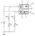
도 54는 복수의 발광소자를 점등 제어하는 구동 회로를 설명하는 도면이다.54 is a diagram illustrating a driving circuit for controlling lighting of a plurality of light emitting elements.
도 55는 발광소자를 시분할로 점등할 때의 스위치의 제어에 대하여 설명하는 타임 차트도이다.Fig. 55 is a time chart illustrating the control of the switch when the light emitting element is turned on in time division.
도 56은 여기광과 조명광의 광량 밸런스를 조절할 수 있는 전기 회로의 예를 나타내는 도면이다.56 is a diagram illustrating an example of an electric circuit capable of adjusting the light amount balance of the excitation light and the illumination light.
도 57은 여기광과 조명광과의 광량 밸런스를 공장 출하시의 초기설정과 사용자에 의한 임의 조절로 절환할 수 있는 전기 회로를 도시한 도면이다.Fig. 57 is a diagram showing an electric circuit capable of switching the light quantity balance between the excitation light and the illumination light to the initial setting at the time of factory shipment and arbitrary adjustment by the user.
도 58은 여기광과 조명광의 광량 밸런스를 조절할 수 있는 다른 전기 회로예를 나타내는 도면이다.58 is a diagram showing another example of the electric circuit capable of adjusting the light quantity balance of the excitation light and the illumination light.
도 59는 여기광의 조사에 대한 건강 에나멜질과 우식 에나멜질의 형광 발광 상태에 관한 예를 설명하는 그래프이다.Fig. 59 is a graph for explaining an example of the fluorescence emission states of the healthy enamel and caries enamel for irradiation with excitation light;
도 60은 여기광의 조사에 대한 건강 에나멜질과 우식 에나멜질의 형광 발광 상태에 관한 다른 예를 설명하는 그래프이다.Fig. 60 is a graph for explaining another example of the fluorescence emission states of the healthy enamel and the caries enamel for irradiation with excitation light.
도 61은 구강 내의 치아에 있어서의 이변부를 설명하는 도면이다.Fig. 61 is a diagram illustrating a wide side portion in teeth in the oral cavity.
도 62는 핸드피스를 구비한 구강 치료 장치의 개요를 설명하는 도면이다.62 is a view for explaining an outline of an oral treatment device having a handpiece.
본 발명에 의한 치과 진료 장치의 실시 형태를 설명하기 전에, 구강 내의 이변부를 특징적으로 추출할 수 있는 원리에 대하여, 도 59 내지 61을 참조하여 설명 한다.Before describing an embodiment of the dental care apparatus according to the present invention, the principle of characteristically extracting the extraordinary part in the oral cavity will be described with reference to FIGS. 59 to 61.
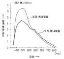
먼저, 도 59에는 여기광의 조사에 대한 건강 에나멜질과 우식 에나멜질의 형광 발광 상태를 설명하는 그래프가 도시되어 있다. 치아에 대하여, 특정 파장을 가지는 여기광이 조사되었을 때에, 치아 상태에 영향을 미친 형광 반사파의 모습이 나타나 있다. 도 59에서는 건강한 치아의 에나멜질의 경우와 우식된 치아의 에나멜질의 경우에 있어서, nm 단위로 나타낸 파장에 대한 치아에 의하여 반사된 방사선의 상대치로 나타낸 방사선 강도 I가 플롯되어 있다. 입사 방사선, 즉, 여기광은 406 nm의 파장을 가진다.First, FIG. 59 is a graph illustrating the fluorescent state of health enamel and caries enamel with respect to excitation light irradiation. When the excitation light having a specific wavelength is irradiated to the tooth, a state of the fluorescence reflected wave which affects the tooth state is shown. In FIG. 59, radiation intensity I is plotted as a relative value of radiation reflected by the tooth with respect to the wavelength expressed in nm in the case of enamel of healthy teeth and of enamel of caries. Incident radiation, ie excitation light, has a wavelength of 406 nm.
도 59의 그래프로부터 알 수 있는 바와 같이, 도시된 각각의 커브는 서로 차이가 난다. 특히, 우식된 치아의 에나멜질에 대한 방사선 강도의 커브는 636 nm와 673 nm와 700 nm인 곳에서 3개의 큰 산을 이루는 강도를 나타내고 있다. 이 건강한 치아의 에나멜질과 우식된 치아의 에나멜질에 있어서의 형광 거동의 차이를 이용하면, 636 nm와 673 nm와 700 nm의 반사광을 확인할 수 있다, 즉, 이들 적색의 형광이 눈에 보이는 것인데, 이러한 적색 부분을 관찰함으로써, 우식의 유무나 대략적인 우식의 진행 정도를 진단할 수 있다.As can be seen from the graph of FIG. 59, each curve shown is different from each other. In particular, the curves of the radiation intensity for enamel of carious teeth show the intensity of three large acids at 636 nm and 673 nm and 700 nm. Using the difference in fluorescence behavior between the enamel of healthy teeth and the enamel of caries, the reflected light at 636 nm, 673 nm and 700 nm can be seen, ie these red fluorescences are visible. By observing such a red part, the presence or absence of caries and the approximate degree of caries can be diagnosed.
또한, 도 60에는 여기광의 조사에 대한 건강 에나멜질과 우식 에나멜질의 형광 발광 상태에 관한 다른 예를 설명하는 그래프가 도시되어 있다. 치아에 대하여, 특정 파장을 가지는 여기광이 조사되었을 때에, 치아 상태에 영향을 미친 형광 반사파의 모습이 나타나 있다. 도 60에서는 건강한 치아의 에나멜질의 경우와 우식된 치아의 에나멜질의 경우에 있어서의, nm 단위로 나타낸 파장에 대한 치아에 의하여 반사된 방사선의 상대치로 표시한 방사선 강도가 플롯되어 있다. 이 경우에 조사한 입사 방사선, 즉, 여기광은 488 nm의 파장을 가지고 있다.In addition, FIG. 60 shows a graph for explaining another example of the fluorescence emission states of the health enamel and the caries enamel against irradiation of excitation light. When the excitation light having a specific wavelength is irradiated to the tooth, a state of the fluorescence reflected wave which affects the tooth state is shown. In FIG. 60, the radiation intensity expressed by the relative value of the radiation reflected by the tooth with respect to the wavelength expressed in nm in the case of enamel of healthy teeth and of enamel of caries is plotted. In this case, the incident radiation, that is, the excitation light, irradiated has a wavelength of 488 nm.
도 60에 도시한 다른 형광 발광 상태의 그래프로부터 알 수 있는 바와 같이, 도시된 각각의 커브는 서로 차이가 나는데, 그 차이가 나는 형태가 도 59에 나타내는 형광 발광 상태의 그래프와 다르다. 건강 에나멜질과 우식 에나멜질의 각각의 방사선 강도 커브는 모두, 여기광의 파장 부근에서 피크를 이루고 있으나, 그 피크의 높이가 차이가 난다. 이러한 사실로부터, 이 건강한 치아의 에나멜질과 우식된 치아의 에나멜질에 있어서의 형광 반사 강도의 차이를 이용하면, 우식의 유무나, 대략적인 우식의 진행 정도에 관한 진단을 실시할 수 있다.As can be seen from the graphs of the different fluorescence states shown in FIG. 60, the curves shown are different from each other, and the form of the difference is different from the graph of the fluorescence states shown in FIG. The radiation intensity curves of the healthy enamel and caries enamel each have a peak near the wavelength of the excitation light, but the heights of the peaks differ. From this fact, by using the difference in the fluorescence reflection intensity between the enamel of the healthy tooth and the enamel of the carious tooth, it is possible to diagnose the presence or absence of caries and the approximate degree of caries progression.
이상에서 설명한 바와 같이, 건강 에나멜질과 우식 에나멜질에 조사된 방사선에 대한 형광 거동의 차이 또는 반사 강도의 차이를 이용하면, 해당 치아가 건강한지, 또는 우식되어 있는 지 판단할 수 있다.As described above, it is possible to determine whether the tooth is healthy or caries by using the difference in the fluorescence behavior or the difference in the reflection intensity with respect to the radiation applied to the healthy enamel and the caries enamel.
이에, 실제로 치아에 있어서의 이변부, 예를 들면, 우식되었거나 또는 치석이나 치구가 부착되어 있는 치아에, 전술한 여기광을 조사하였을 때의 모습을 도 6l에 도시하였다. 도중에서는 예시로서 구강 내의 치열이 도시되고, 대표적으로 치아 Tl 내지 T4로 이루어지는 치열이 도시되어 있다. 도 61에서는 치아 T2와 T3에, 우식 부위 B1, B2가 존재하는 경우를 예시하고 있다. 우식 부위 B1는 완전하게 우식되어 큰 구멍 형상이 된 경우(실선으로 도시)이며, 우식 부위 B2는 치아 내부가 침범되어 있는 경우(파선으로 도시)이다.Thus, Fig. 6L shows a state when the above-mentioned excitation light is actually irradiated on the side of the tooth, for example, a carious tooth or a tooth having tartar or jig attached thereto. The dentition in the oral cavity is shown by way of example in the middle, and the dentition which consists of teeth Tl-T4 is shown typically. In FIG. 61, the case where caries parts B1 and B2 exist in the teeth T2 and T3 is illustrated. The caries part B1 is completely caries and becomes a large hole shape (shown by a solid line), and the caries part B2 is when the inside of a tooth is invaded (shown by a broken line).
이 때, 특정 파장이 선택된 여기광이 조사되면, 치아로부터 형광이 발생한 다. 이 때, 도 59 또는 도 60의 그래프에 도시하는 바와 같이, 건강한 부위와 우식이 발생한 부위는 형광 반사 강도가 다르므로, 치료 작업자가 이 형광을 검출할 수 있는 필터 기능을 구비한 안경 또는 고글을 사용하여 육안으로 관찰하거나, 또는 핸드피스에 배치된 해당 필터 기능을 구비한 프로텍트판 등을 통하여 보면, 우식 부위 B1 및 B2를 다른 건전부와 구별하여 인식할 수 있다. 또한, 이 필터 기능은 단순하게 여기광을 차단하는 특성을 가진 것이면 된다. 예를 들면, 405 nm의 여기광이면, 440 nm 보다 긴 파장의 영역만을 투과하는 필터이면 좋다.At this time, when excitation light with a specific wavelength is selected, fluorescence is generated from the tooth. At this time, as shown in the graph of FIG. 59 or FIG. 60, since the healthy site and the site of caries have different fluorescence reflection intensities, glasses or goggles equipped with a filter function capable of detecting this fluorescence can be treated by a treatment worker. When viewed visually or through a protect plate equipped with a corresponding filter function disposed on the handpiece, caries sites B1 and B2 can be recognized separately from other healthy parts. In addition, this filter function should just have the characteristic which interrupts excitation light. For example, as long as it is 405 nm excitation light, what is necessary is just the filter which permeate | transmits only the area | region of wavelength longer than 440 nm.
우식 부위 B2는 우식 부위 B1보다 그 강도가 약해 보인다. 그 때문에, 진료 작업 중에 있어서, 이 여기광을 계속 조사함으로써, 우식 부위 B1, B2의 존재를 파악할 수 있고, 또한 어느 우식 부위를 먼저 치료하면 좋은지 판단하기 쉬워진다. 또한 치료를 개시한 후에도, 치료 대상 부분을 특정할 수 있고, 치료 진행 상태를 명확하게 파악할 수 있어, 치료하지 못하고 남기는 부분이 생기거나, 지나치게 많이 깎게 되는 것을 없앨 수 있다. 또한, 진료 기구를 일일이 바꿀 필요가 없기 때문에 작업 효율이 향상된다. 기본적으로, 우식 부위에서는 본래의 부위의 색과 다른 형광색이 나오므로, 그 색을 발하는 부분을 치료한다. 치석, 치구의 부착 부위도 마찬가지이다.The caries site B2 appears to be less intense than the caries site B1. Therefore, by continuously irradiating this excitation light during a medical examination work, it is possible to grasp the presence of caries sites B1 and B2, and to easily determine which caries sites should be treated first. In addition, even after the start of treatment, the portion to be treated can be specified, and the progress of treatment can be clearly understood, and the portion left behind without treatment or cut off too much can be eliminated. In addition, the work efficiency is improved because there is no need to change the treatment apparatus. Basically, since the caries part has a fluorescent color different from that of the original part, the part giving off the color is treated. The same also applies to the tartar and plaque attachment sites.
치아와 관련되는 이변부로서, 예를 들면 우식 부위, 연화 상아질, 치석, 치구, 바이오 필름, 결손, 금 등을 들 수 있으나, 이들 이변부에 조사되었을 때에 형광 거동의 차이 또는 반사 강도의 차이를 나타내는 특정의 파장으로서는 405±50 nm의 근자외선 영역, 470±30 nm의 청색 영역, 700±100 nm의 적색 영역, 적외선 영역, 또는 근적외선 영역의 광을 들 수 있지만 이러한 파장에 한정되는 것은 아니다. 또한, 적외선 영역, 또는 근적외선 영역의 광은 여기광으로서 사용하기도 하지만, 적외선 그 자체의 반사광을 관찰하는 것도 가능하다. 상기는 일례이며 본 발명은 이것에 한정되는 것은 아니다.Examples of the abdominal region associated with the teeth include caries, softening dentin, calculus, plaque, biofilm, defects, and gold. Specific wavelengths shown include light in the near ultraviolet region of 405 ± 50 nm, the blue region of 470 ± 30 nm, the red region of 700 ± 100 nm, the infrared region, or the near infrared region, but are not limited to these wavelengths. In addition, although the light of an infrared region or a near infrared region is used as excitation light, it is also possible to observe the reflected light of infrared rays itself. The above is an example and this invention is not limited to this.
이들 광은 발광 다이오드(LED)나, 레이저 다이오드(LD)를 포함한 반도체 레이저 소자 등의 발광소자를 사용함으로써 간단하게 발생할 수 있고, 이들 소자는 렌즈부를 구비한 소자 모듈에 형성되어 소형의 광원으로서 사용할 수 있다. LED 소자로서는 백색 LED를 사용하여도 좋다. 또한, 이들 소자 이외에도, 발광소자로서 램프 광원, 예를 들면, 할로겐 램프 등에 의한 백색광을 사용할 수도 있다. 이 때에는 소정의 파장을 낼 수 있는 광학 필터를 조합함으로써 실현할 수 있다.These lights can be easily generated by using light emitting elements such as light emitting diodes (LEDs) and semiconductor laser elements including laser diodes (LDs), and these elements are formed in an element module having a lens portion to be used as a compact light source. Can be. As the LED element, a white LED may be used. In addition to these elements, a white light source using a lamp light source, for example, a halogen lamp, may be used as the light emitting element. In this case, this can be achieved by combining an optical filter capable of producing a predetermined wavelength.
우식 부위에는, 예를 들면, 상술한 파장이 405 nm인 여기광을 사용할 수 있고, 우식 부위로부터의 형광에 의하여 검출 가능하고, 연화 치아의 주체가 되는 조직에 대하여도, 그 여기광의 조사에 의한 형광으로 검출할 수 있다. 치석, 치구, 바이오 필름에 대하여도, 여기광을 조사하면, 치석, 치구로부터의 형광으로 검출이 가능하다. 또한, 치석이나 치구에 관하여는 부착 상태를 잘 알 수 있으므로, 세부의 형태를 잘 알 수 있는 적외광을 조사함으로써, 치석이나 치구의 존재를 확인할 수 있다.As the caries site, for example, excitation light having the above-described wavelength of 405 nm can be used. The excitation light can also be detected by the fluorescence from the caries site, and the irradiated light is also exposed to the tissue that is the subject of the softened tooth. It can be detected by fluorescence. Also in the calculus, the plaque, and the biofilm, when excitation light is irradiated, it can be detected by the fluorescence from the plaque, the plaque. In addition, since the attachment state can be known well about the tartar and the jig, the presence of the tartar or the jig can be confirmed by irradiating the infrared light which is well known in detail.
치석, 치구, 바이오 필름의 검출에 대하여서는 400±30 nm, 바람직하게는 405 nm 또는 375 nm의 광을 조사하면, 명확하게 구별할 수 있고, 스케일러 등의 핸드피스에 광 조사 수단의 광으로서 적용하는데 최적이다. 이 때, 450 nm 이상의 장 파장을 통과시키는 광학 필터를 통하여 관찰하면, 400±30 nm, 바람직하게는 405 nm 또는 375 nm의 조사된 여기광이 차단되어 더 명료하게 관찰할 수 있다. 또한, 이 절단 파장은 일례이며, 발명은 이것에 한정되는 것은 아니다.The detection of tartar, jig, and biofilm can be clearly distinguished by irradiation with light of 400 ± 30 nm, preferably 405 nm or 375 nm, and is applied as light of light irradiation means to a handpiece such as a scaler. It is most suitable to. At this time, when observed through an optical filter passing a long wavelength of 450 nm or more, the irradiated excitation light of 400 ± 30 nm, preferably 405 nm or 375 nm is blocked and can be observed more clearly. In addition, this cutting wavelength is an example, and invention is not limited to this.
또한, 녹색계의 광을 조사하면, 결손, 금 등을 보다 명료하게 관찰할 수 있다. 또한 부위가 다르면, 광의 반사 강도, 흡수의 정도가 다르므로, 반사·흡수의 차이가 현저한 파장의 광을 조사하고, 그 차이를 확인함으로써, 이변부를 확인할 수도 있다.In addition, when green light is irradiated, defects, gold, and the like can be observed more clearly. In addition, since the reflection intensity and the degree of absorption of the light are different when the sites are different, the two-sided part can be confirmed by irradiating light having a wavelength with a significant difference in reflection and absorption and confirming the difference.
또한, 이 이변부의 확인 시에, 전술에서는 치료 작업자가 여기광에 의한 형광을 검출할 수 있는 필터 기능을 구비한 안경 또는 고글을 사용하고, 또는 인스트루먼트에 배치된 해당 필터 기능을 구비한 프로텍트판 등을 통하여 육안으로 관찰한다고 하였지만, 이 경우에는 형광만이 검출되어 치료 작업자에게는 이변부의 상황이 부각되어 보이고, 주변 부분은 어둡게 보인다. 그 때문에, 이변부는 명확하게 되지만, 다른 건전부의 상황은 파악되지 않거나, 또는 해당 이변부의 정확한 위치를 인식할 수 없게 된다.In addition, in confirming this two-sided part, in the above description, the treatment worker uses the glasses or goggles provided with the filter function which can detect the fluorescence by an excitation light, or the protector board with the said filter function arrange | positioned in the instrument, etc. Although it is said that it is observed through the naked eye, in this case, only the fluorescence is detected so that the situation of the condyle is highlighted by the treatment worker, and the surrounding part is dark. For this reason, the two-sided portion becomes clear, but the situation of the other healthy portion is not grasped or the exact position of the two-sided portion cannot be recognized.
그러나, 이변부에 조사하는 여기광의 파장이 가시광선 영역에 있는 경우에는, 특히 형광을 검출하는 필터 기능을 가지는 기구를 사용하지 않아도, 치료 작업자는 이변부에 대하여, 그 주변의 색과 다른 색으로 관찰할 수 있고, 또한 여기광의 색에 따라서 이변부 주변의 상황도 파악할 수 있다.However, in the case where the wavelength of the excitation light irradiated to the side region is in the visible region, the treatment worker has a color different from that of the surrounding region with respect to the side region even if a device having a filter function for detecting fluorescence is not used. It can observe and can also grasp | a situation of the periphery part according to the color of excitation light.
또한, 여기광의 투과를 배제하는 필터 기능을 구비한 안경 또는 고글을 사용하거나, 또는 인스트루먼트에 배치된 해당 필터 기능을 구비한 프로텍트판 등을 통 하여 육안으로 보면, 치료 작업자는 이변부로부터의 형광에 의하여 이변부의 상황을 인식할 수 있고, 또한 여기광만을 조사하고 있는 경우에는 여기광의 조사에 방해를 받지 않고, 외부로부터 구강 내에 들어가는 광에 의하여, 이변부 주변의 상황을 파악할 수 있다. 또는 여기광과 조명용 백색광의 양쪽 모두를 동시에 조사하고 있는 경우에도, 이변부 뿐만 아니라 이변부의 주변 조직의 상황을 정확하게 파악할 수 있고, 또한 이변부의 주변도 밝아져, 그 상황을 인식하기 쉬워진다. 그 주변 조직의 색조도 충실하게 표현된다.In addition, using the eyeglasses or goggles provided with the filter function which excludes the transmission of excitation light, or visually through the protective plate equipped with the said filter function arrange | positioned at the instrument, the treatment worker is exposed to the fluorescence from a side part. By this, the situation of the concave part can be recognized, and when only the excitation light is irradiated, the situation around the convex part can be grasped by the light which enters the oral cavity from the outside without being disturbed by the irradiation of the excitation light. Alternatively, even when both the excitation light and the illumination white light are irradiated at the same time, the situation of the surrounding tissue as well as the side of the side can be grasped accurately, and the periphery of the side of the side is also brightened, making it easy to recognize the situation. The tone of the surrounding tissues is also faithfully expressed.
또한 소정 파장의 광을 방사하는 발광소자가 하나만 구비되어 있어도 무방하나, 파장이 다른 광을 방사하는 복수의 발광소자를 준비하여 두면, 절환 스위치의 조작으로 발광소자의 구동을 제어함으로써, 특정 파장의 여기광만의 선정 조사, 다른 파장의 여기광으로의 절환 조사, 또는 조명광과 여기광의 절환 조사 등의 조사 패턴을 실현할 수 있다. 조명광과 여기광의 절환 조사의 경우에는 조명광과 여기광의 시분할의 점등 제어에 의하여, 구강 내의 조명과 이변부의 추출을 동시에 실시할 수 있다.In addition, only one light emitting device for emitting light having a predetermined wavelength may be provided. However, if a plurality of light emitting devices for emitting light having different wavelengths are prepared, the driving of the light emitting device can be controlled by operating a switching switch. Irradiation patterns such as selection irradiation of only the excitation light, switching irradiation to excitation light of different wavelengths, or switching irradiation of illumination light and excitation light can be realized. In the case of the switching irradiation of the illumination light and the excitation light, the illumination in the oral cavity and extraction of the concave part can be simultaneously performed by the lighting control of the time division of the illumination light and the excitation light.
다음으로, 본 발명에 의한 구강 내를 치료하는 치료 진료 장치의 제1 실시 형태에 대하여, 전술한 바와 같이, 구강 내의 이변부를 특징적으로 추출할 수 있는 광을 조사할 수 있는 광 조사 수단을 구비한 핸드피스의 적용예를 실시예 1 내지 7로 나누어 설명한다.Next, with respect to the first embodiment of the treatment treatment apparatus for treating the oral cavity according to the present invention, as described above, the light irradiation means capable of irradiating light that can extract the characteristic region of the oral cavity is provided. Application examples of the handpiece will be described by dividing them into Examples 1 to 7.
또한, 본 발명에 있어서는 광 조사 수단은 적어도 여기광을 방출하는 광원을 포함한 광을 조사하는 수단이며, 광원만으로 이루어지는 경우에도, 광원과 상기 광 원으로부터의 상기 여기광을 상기 이변부를 향하여 조사하는 조사부로 이루어지는 경우도 있을 수 있다.Further, in the present invention, the light irradiation means is a means for irradiating light including at least a light source for emitting excitation light, and an irradiation unit for irradiating the excitation light from the light source and the light source toward the two-sided portion, even when only the light source is used. It may be made of.
조사부로서는 예를 들면 광원으로부터의 광을 도광하고, 상기 이변부를 향하여 조사하는 광가이드 부재의 출사면이나, 광섬유의 선단부(광가이드 부재나 광섬유로부터 도광되는 투광부재가 설치되고, 상기 투광부재로부터 이변부에 조사하는 경우에는 그 투광부재)나, 광원으로부터의 광에서 소정 파장의 광을 걸러내어 상기 이변부를 향하여 조사하는 광학 필터 등이 있다.As the irradiating portion, for example, an emission surface of the light guide member for guiding light from a light source and irradiating toward the two side portions, or a distal end portion of the optical fiber (a light guide member or a light transmitting member that is guided from the optical fiber) is provided, In the case of irradiating to the part, the light transmitting member), an optical filter for filtering the light having a predetermined wavelength from the light from the light source, and irradiating the light toward the two side parts.
또한, 광원은 예를 들면 발광소자이며, 단수의 발광소자로 이루어지는 경우도 포함되고, 복수로 이루어지는 경우도 포함된다.In addition, a light source is a light emitting element, for example, includes the case where it consists of a single light emitting element, and includes the case where it consists of a plurality.
실시예 1Example 1
실시예 1에서는 본 실시 형태에 의한 광 조사 수단을 에어 터빈 핸드피스에 적용한 경우이고, 도 1A 및 1B에, 그 에어 터빈 핸드피스의 헤드부에, 광 조사 수단을 설치한 개략 구성이 나타나 있다.In Example 1, it is a case where the light irradiation means which concerns on this embodiment is applied to an air turbine handpiece, and the schematic structure which provided the light irradiation means in the head part of the air turbine handpiece is shown by FIG. 1A and 1B.
도 1A 및 1B에 있어서, 1은 핸드피스 본체, 2는 핸드피스 헤드부, 3은 바 등의 공구류인 치료구(진료구의 일례)를 나타내고 있다. 도 1A 및 1B에서는 핸드피스의 선단측의 일부가 도시되어 있고, 설명을 간단화하기 위하여, 다른 부분의 도시를 생략하고 있으나, 실제로는 핸드피스는 헤드부(2)와 반대측에 있어서 핸드피스(1)와 착탈이 자유롭게 장착할 수 있는 조인트부를 구비하고 있고, 그 조인트부가 튜브를 사이에 두고 에어 등의 공급 장치에 접속되어 있다.1A and 1B, 1 shows a treatment tool (an example of a treatment tool) which is a tool such as a handpiece main body, 2 a handpiece head portion, and 3 a bar. In FIGS. 1A and 1B, a part of the front end side of the handpiece is shown, and for the sake of simplicity, the illustration of other parts is omitted, but in reality, the handpiece is located on the side opposite to the
도 1A에서는 광 조사 수단으로서 LED 또는 반도체 레이저에 의한 발광소 자(L)가 치료구(3)가 장착되는 핸드피스 헤드부(2)의 근방 부분의 한 지점에, 발광소자(L)를 노출한 상태로 배치하고 있다. 그 발광소자(L)의 설치 자세를, 치료구(3)의 축방향에 비하여 약간 경사시켰고, 치료구(3)의 설치시에 있어서, 그 광의 조사 방향이 도중에 파선으로 나타내는 바와 같이, 치료구(3)의 축방향 전방을 조사하도록 선정되어 있다. 또한, 발광소자(L)는 투광성 보호 커버 등으로 가릴 수도 있다. 또한, 발광소자(L)의 사용수는 광출력이 충분하면 1개라도 좋지만, 출력이 부족한 경우에는 필요한 출력을 얻을 수 있도록, 복수개의 발광소자(L)을 사용하여도 된다. 또한, 복수개의 발광소자(L)를 사용하는 경우는 파장이 다른 발광소자를 조합하여도 좋다. 1개의 발광소자로 파장이 다른 광을 발광할 수 있는 발광소자를 사용하여도 된다.In FIG. 1A, the light emitting element L by the LED or the semiconductor laser as the light irradiation means exposes the light emitting element L at a point in the vicinity of the
한편, 도 1B에서는 광 조사 수단으로서 복수의 발광소자(L)를 설치한 예가 도시되어 있고, 발광소자(L)가 치료구(3)의 축을 둘러싸고, 각 발광소자(L)의 조사 방향이 그 축과 거의 평행하도록 하고, 핸드피스 헤드부(2)의 선단부 주연에 배치되어 있다. 도 1A의 경우에는 발광소자(L)의 설치 각도에 따라서는 치료구(3)에 의한 그림자가 발생하기도 하지만, 도 1B의 경우에는 발광소자(L)의 복수가 치료구(3)를 둘러싸고 배치되어 있기 때문에, 도중에 파선으로 나타내는 바와 같이, 그것들에 의한 조사광은 각 발광소자(L)로부터 직접 출사되어, 치료구(3)의 전방을 조사하고, 치료구(3)에 의한 그림자는 발생하지 않는다.1B shows an example in which a plurality of light emitting elements L are provided as light irradiation means, the light emitting elements L enclosing the axis of the
다음으로, 핸드피스에 있어서의 광 조사 수단으로서 도 1A에 도시된 한 지점에 집중하여 발광소자(L)를 설치하였을 경우의 구체예 1에 대하여, 도 2에 나타내 었다. 도 2에서도, 핸드피스 헤드부(2)를 중심으로 하여 도시되어 있다.Next, FIG. 2 shows a specific example 1 in the case where the light emitting element L is provided with focus on one point shown in FIG. 1A as the light irradiation means in the handpiece. In FIG. 2, the
도 2에 도시하는 바와 같이, 핸드피스 본체(1)와 핸드피스 헤드부(2)의 접합부 부근으로서, 치료구가 장착되는 측에 개구된 오목부(4)가 형성된다. 이 오목부(4)의 크기는 발광소자(L)가 들어갈 수 있는 크기로 선정되고, 그 오목부(4)의 내벽면에는 도금 등에 의한 반사재(5)가 피착되어 있다. 또한, 오목부(4)의 통로에, 투명한 보호 부재가 설치되어도 좋다.As shown in FIG. 2, the recessed
오목부(4)의 내부에 설치된 발광소자(L)의 단자로부터는 도시되어 있지 않지만, 점등시키는 급전을 위한 배선이 핸드피스 본체(1)의 내부에 뻗어 있다. 이 배선은 핸드피스의 조인트부에 접속된 튜브를 거쳐 공급 장치까지 연장되고, 예를 들면, 핸드피스 본체(1)에 설치된 스위치의 조작으로, 발광소자(L)의 점등 또는 소등이 제어된다. 또는 별도로 설치된 스위치 조작에 의한 것이라도 좋다.Although not shown from the terminal of the light emitting element L provided in the recessed
오목부(4) 내에 설치되는 발광소자(L)는, 전술한 바와 같이, 405±50 nm의 근자외선 영역, 470±30 nm의 청색 영역, 700±100nm의 적색 영역, 적외선 영역, 또는 근적외선 영역의 광 중 어느 하나를 발광하는 LED 또는 반도체 레이저가 선택된다. 이 발광소자(L)가 1개만 설치되어 있어도 되나, 출력이 부족한 경우에는 도 2에 나타내는 발광소자의 정면도와 같이, 1개의 큰 발광소자로 할 수도 있다. 또한, 도 2에 나타내는 발광소자의 다른 예에 의한 정면도와 같이, 동일 파장 또는 다른 파장의 광을 발광하는 복수의 발광소자를 설치할 수도 있다.As described above, the light emitting element L provided in the
오목부(4) 내에, 발광소자(L)을 복수개 설치하는 경우에는, 각각 다른 파장의 광을 발광하는 발광소자를 설치할 수도 있다. 이 경우에는 배선 중에 설치되는 스위치의 절환에 의하여, 다른 이변부의 치료에 대하여 편리한 것이 된다. 또한, 복수개의 발광소자 중, 몇 가지를 단순한 조명용으로 할 수도 있다. 이 경우에는 조명용 발광소자(L)를 점등하여 구강 내를 관찰하고, 이변부로 보이는 부위를 발견하였을 때, 여기광의 조사로 곧바로 절환되어 편리한 것이 된다.In the case where a plurality of light emitting elements L are provided in the
도 2에 나타낸 구체예 1에서는 발광소자(L)로서 LED 또는 반도체 레이저의 발광소자를 사용하였지만, 도 3에는 발광소자(L)로서, 할로겐 램프 등의 램프 광원을 사용한 제2 구체예를 나타내었다. 도 3에 도시한 핸드피스는 도 2에 나타낸 구성과 같지만, 오목부(4)에 설치되는 발광소자 (L)가, 예를 들면 할로겐 램프인 것이 특징이다.In Example 1 shown in FIG. 2, a light emitting element of an LED or a semiconductor laser is used as the light emitting element L. In FIG. 3, a second example of using a light source such as a halogen lamp as the light emitting element L is shown. . Although the handpiece shown in FIG. 3 is the same as the structure shown in FIG. 2, the light emitting element L provided in the recessed
할로겐 램프의 접속 단자(6)는 핸드피스(1) 측에 설치된 접속 단자(번호 없음)에 설치되어 고정된다. 또한, 핸드피스(1)의 오목부(4)의 개구에, 할로겐 램프로부터 방출되는 광으로부터, 소정의 여기광을 선택하는 개구(4)에 착탈 가능하게 한 광 필터 (F)가 구비된다. 광 필터(F)를 주파수 선택 종류가 다른 광 필터(F)에 착탈 교환 가능하게 하면, 다른 파장의 여기광을 조사할 수 있다. 이 광 필터(F) 대신에, 단순한 투명한 유리 등의 보호 부재로 교환하면, 일반적으로 사용되는 조명 장치로 할 수 있다.The connecting
이상에서 설명한 제1 및 제2 구체예에서는 광조명 수단으로서의 발광소자(L)가 고정적으로 설치된 상태의 것이었지만, 광조명 수단을 필요로 하지 않는 경우, 또는 발광소자(L)로부터의 여기광의 종류를 변경하고 싶은 경우, 또한 단순한 조명 장치를 설치하고 싶은 경우가 있다. 이러한 경우에 대처할 수 있도록, 광조명 수단 을 핸드피스 헤드부에 있어서, 착탈이 자유롭게 할 수 있는 구체예 3을, 도 4A 및 4B에 나타내었다.In the first and second specific examples described above, the light emitting element L as the light illuminating means is in a fixed state, but when no light illuminating means is required or the kind of excitation light from the light emitting element L If you want to change, you may also want to install a simple lighting device. In order to cope with such a case, the specific example 3 which can be attached or detached at the handpiece head part by the light illumination means is shown to FIG. 4A and 4B.
구체예 3에 의한 핸드피스의 구성은 구체예 1 및 2의 경우와 같지만, 구체예 3에서는 발광소자(L)가 설치되는 오목부(4)를 포함한 핸드피스 헤드부(2)의 선단 부분이 헤드부와 별체로 형성된 헤드 별체 부재(9)로 구성되어 있다. 이 헤드 별체 부재(9)에는 헤드부(2)에 형성된 계합부에 계합하는 계합 부재(11)가 상기 부재와 일체적으로 형성되어 있고, 또는 상기 부재(9)를 핸드피스 본체(l)에 고정하는 나사구멍(10)을 가지고 있다.The structure of the handpiece according to
도 4A에는 헤드 별체 부재(9)가 핸드피스 헤드부(2)에 고정된 상태가, 그리고, 도 4B에는 헤드 별체 부재(9)가 핸드피스 헤드부(2)로부터 분리된 상태가 도시되어 있다. 발광소자(L)은 헤드 별체 부재(9)에 형성된 오목부(4) 내에 설치되어 있고, 헤드 별체 부재(9)가 헤드부(2)에 고정되었을 때, 발광소자(L)에 급전하기 위한 접속 단자(12)가 설치되어 있다.4A shows a state in which the head
이 때, 광 조명 수단을 필요로 하지 않는 경우에는 발광소자(L)를 설치하지 않은 헤드 별체 부재로 하거나, 또는 오목부(4) 자체를 설치하지 않은 헤드 별체 부재로 한다. 또한, 발광소자(L)로부터의 여기광의 종류를 변경하고 싶은 경우에는 종류가 다른 여기광을 발광하는 발광소자를 설치한 헤드 별체 부재를 준비하여 두고, 이것을 교환하도록 한다. 또한, 단순한 조명 장치를 설치하고 싶은 경우에는 백색광을 발광하는 발광소자를 설치한 헤드 별체 부재를 준비하여, 이것을 교환하면 좋다. 또한, 다른 파장의 여기광을 발광하는 LED 등의 발광소자와 백색광을 발 광하는 LED 등의 발광소자를 갖춘 헤드 별체 부재를 준비하여 두면 스위치의 전환에 의하여 발광소자의 선택을 실시할 수 있다.At this time, when no light illuminating means is required, the head separate member without the light emitting element L is provided, or the head separate member without the
이상의 도 2 내지 도 4에 도시한 구체예 1 내지 3은 도 1A에 도시한 바와 같이, 발광소자(L)가 치료구(3)가 설치되는 핸드피스 헤드부(2)의 근방 부분의 한 지점에 설치되는 경우였지만, 이하에, 도 1B에 도시하는 바와 같이, 복수의 발광소자(L)가 치료구(3)의 축을 둘러싸고, 각 발광소자(L)의 조사 방향이 상기 축과 거의 평행이 되는 경우에 대하여, 도 5 내지 도 7을 참조하여, 그 구체예를 설명한다.2 to 4, the specific examples 1 to 3 shown in FIG. 1A show a point of the vicinity of the portion of the
도 5에, 구체예 4가 개시되어 있으나, 도 5에 있어서 핸드피스에 관한 도시 방법은 도 2와 같다. 구체예 3에서는, 도 5에 도시하는 바와 같이 복수의 발광소자(L)가 핸드피스 헤드부(2)의 선단부 주연에 설치된 치료구(3)를 둘러싸도록 설치된 홈(8) 내에 설치되어 있다. 치료구(3)의 선단 방향에서 본 핸드피스 헤드부(2)의 선단부의 모습이 도 5에 개시되어 있다. 홈(8) 대신에, 복수의 오목부를 설치하여도 좋다.Although FIG. 5 discloses a specific example 4, the drawing method of the handpiece in FIG. 5 is the same as that of FIG. In the specific example 3, as shown in FIG. 5, the some light emitting element L is provided in the groove |
구체예 4의 경우에도, 개구된 홈(8)의 깊이 및 폭은 발광소자(L)가 수납되도록 선정되고 그 홈(8)의 내벽면에는 도금 등에 의한 반사재(5)가 피착되어 있다. 또한, 홈 (8)의 개구에 투명한 보호 부재가 설치되어 있어도 좋다.Also in the case of the specific example 4, the depth and width of the
홈(8)의 내부에 설치된 발광소자(L)의 단자로부터는, 도시되어 있지 않지만, 점등시키는 급전을 위한 배선이 핸드피스 본체(1)의 내부에 뻗어 있다. 이 배선은 핸드피스의 조인트부에 접속된 튜브를 거쳐 공급 장치에까지 연결되어 있고, 예를 들면, 핸드피스 본체(1)에 설치된 스위치의 조작으로, 발광소자(L)의 점등 또는 소등이 제어된다. 또는 별도로 설치된 스위치 조작에 의하는 것이라도 좋다.Although not shown from the terminal of the light emitting element L provided in the
홈(8) 내에 설치되는 발광소자(L)는 전술한 바와 같이, 405±50 nm의 근자외선 영역, 470±30 nm의 청색 영역, 700±100nm의 적색 영역, 적외선 영역, 또는 근적외선 영역의 광의 어느 하나를 발광하는 LED 또는 반도체 레이저가 선택된다. 복수의 발광소자(L) 모두가 동일광을 발광하도록 설치될 수도 있지만, 복수의 발광소자(L) 중에서, 다른 파장의 광을 발광하도록 설치할 수도 있다. 이 경우에는 배선 중에 설치되는 스위치의 변경에 의하여, 다른 이변부의 치료에 대하여 편리한 것이 된다. 또한, 복수개의 발광소자 중에서, 몇 개를 단순한 조명용으로 할 수도 있다. 이 경우에는 조명용의 발광소자(L)를 점등하여, 구강 내를 관찰하고, 이변부로 보이는 부위를 발견하였을 때, 여기광의 조사로 곧바로 절환되어 편리한 것이 된다. 각 발광소자의 점등의 절환은 시분할로 자동적으로 절환하여도 좋고, 절환 스위치등에 의하여 수동으로 실시하여도 된다.As described above, the light emitting element L provided in the
도 5에 도시한 구체예 4에서는 광 조사 수단으로서의 발광소자(L)가 진료구의 장착부 근방에 고정적으로 설치된 상태의 것이지만, 광 조사 수단을 필요로 하지 않는 경우, 또는 발광소자(L)로부터의 여기광의 종류를 변경하고자 하는 경우, 또한 단순한 조명 장치를 설치하고자 하는 경우, 광 조사 수단을 핸드피스 헤드부에 착탈 교환할 수 있는 구체예 5를 도 6A 및 6B, 도 7에 도시하였다.In the specific example 4 shown in FIG. 5, although the light emitting element L as a light irradiation means is fixedly installed in the vicinity of the attachment part of a medical office, excitation from the light emitting element L when the light irradiation means is not needed, or 6A and 6B and 7 show a specific example 5 in which the light irradiation means can be attached and detached from the handpiece head part when the type of light is to be changed or when a simple lighting device is to be provided.
구체예 5에 의한 핸드피스의 구성은 광 조사 수단을 핸드피스 헤드부(2)에 착탈 교환이 자유롭게 하기 위하여, 발광소자가 설치되어 있는 헤드 별체 부재(43) 를 헤드부(2)에 대하여 나합에 의하여 착탈할 수 있는 구성으로 하고 있다. 핸드피스 헤드부(2)의 선단부의 형상에 맞추어 원환상(圓環狀)의 배선 기판(49)에, 예를 들면, 도 7에 도시하는 바와 같이, 복수의 발광소자(L)를 배치하고 있다. 이 배선 기판(49)이 핸드피스 헤드부(2)의 선단부에 헤드 별체 부재(43)를 사용하여 설치되고, 각 발광소자(L)가 급전을 위한 배선(미도시)에 접속된다.In the structure of the handpiece according to the fifth embodiment, the head
도 7은 구체예 5에 있어서의 도 6A와 동일한 구성의 일부 파단 사시도를 나타내고 있다. 헤드 별체 부재(43)는 중앙에 치료구(3)을 받아들이기 위한 중공부분이 있는 원환상의 부재이며, 핸드피스 헤드부(2)의 저부와 거의 동일한 외경을 가진다. 헤드 별체 부재 (43)의, 핸드피스 헤드부(2)에 장착시에 대면하는 면(49c)에는 원환상의 홈(49a)이 헤드 별체 부재(43)의 원환상의 형태에 따라서 설치되고, 이 원환상의 홈(49a)에 배선 기판(49)이 끼워지도록 되어 있다. 원환상의 홈(49a)의 저부에는 배선 기판(49)에 설치되는 발광소자(L)의 배치에 대응하는 위치에, 관통공(49b)이 설치되어 있다. 관통공(49b)은 원환상의 홈(49a)의 저부로부터, 헤드 별체 부재(43)의 원환상의 홈(49a)의 개방측과 반대측의 면(49d)까지 관통하고 있다.FIG. 7: shows the partially broken perspective view of the structure similar to FIG. 6A in the specific example 5. As shown in FIG. The head
헤드 별체 부재(43)에는 원환상의 홈(49a)이 형성되므로, 원환상의 홈(49a)의 내측에, 헤드 별체 부재(43)의 일부가 헤드 별체 내벽부재(46a)로서 형성되고,원환상의 홈(49A)의 외측에, 헤드 별체 부재(43)의 일부가 헤드 별체 외벽부재(46b)로서 형성된다. 헤드 별체 내벽부재(46a)의 외주에는 도 6A, 도 6B에 나타내는 핸드피스 헤드부(2)의 저부로부터 돌출하는 헤드측 계합부(44)에 착탈이 자유 롭게 나합하기 위한 나합부(47)가 설치되어 있다. 헤드 별체 부재(43)에는 핸드피스 헤드부(2)에의 장착시에는 원환상의 홈(49a)에 배선 기판(49)을 발광소자(L)를 저부측을 향하여 끼우고, 헤드측 계합부(44)에 나합부(47)를 나합한다.Since the
배선 기판(49)에는 헤드 별체 부재(43)의 핸드피스 헤드부(2)에의 장착시에, 도 6B의 헤드측 계합부(44)의 외주에 설치된 2개의 띠모양 도전 부재로 이루어지는 링 형상의 접속 단자(45)에 접하도록, 접점(50)을 가지는 접점 부재(51)가 설치되어 있다. 접점 (50)은 헤드 별체 부재(43)의 핸드피스 헤드부(2)에의 장착시에, 링모양 접속 단자(45)의 어느 부분에 접하고, 급전되도록 위치 결정되어 있다. 접점 부재(51)는 배선 기판(49)에 설치하여도 좋지만, 헤드 별체 부재(43)에 설치하여, 배선 기판(49)에 접속하여 급전되도록 하여도 된다.In the
이 때, 복수의 발광소자(L)가 치료구(3)의 축을 둘러싸듯이 환상으로 배치되고, 도 6B에서 도시하는 바와 같이, 각 발광소자(L)의 광 방출 방향이 치료구(3)를 설치하였을 때에 치료구(3)의 선단의 방향으로 향하도록, 발광소자(L)를 약간 내측에 경사시켜 설치하였다. 여기에 설치되는 발광소자(L)로서는 도 5에 나타낸 구체예 4의 경우와 같다.At this time, the plurality of light emitting elements L are arranged annularly so as to surround the axis of the
이와 같은 구체예 5의 구성으로 하면, 광 조사 수단이 핸드피스 헤드(2)의 일부를 형성하도록 할 수 있으므로, 광 조사 수단으로서의 공간을 작게 할 수 있는 동시에, LED 또는 반도체 레이저에 의한 소자를 이용하고 있으므로 광원의 냉각 기구가 불필요하게 되고, 핸드피스 등의 기구를 대형화하지 않고 조명 기능을 부가할 수 있어, 소형 경량으로 사용하기 쉬운 치과용 핸드피스를 얻게 된다.According to the structure of this specific example 5, since the light irradiation means can form a part of the
이상에 설명한 구체예 4는 발광소자(L)는 핸드피스 헤드부에 고정적으로 설치되어 있는 경우였지만, 도 7에 나타낸 구체예 5는 발광소자를 포함한 광 조사 수단이 핸드피스 헤드부와 착탈이 자유롭게 구성된 경우의 일례이다.In the specific example 4 described above, the light emitting element L is fixedly installed in the handpiece head portion. In the specific example 5 shown in FIG. 7, the light irradiation means including the light emitting element is detachably attached to the handpiece head portion. This is an example of the case.
다음으로, 도 8A 및 8B에, 복수의 발광소자(L)를 상기 선단부 주연에 직접 노출시켜 설치하는 구체예 6을 나타내었다. 구체예 6은 구체예 4에 있어서의 발광소자의 설치 방법을 변경한 것이고, 스케일러의 핸드피스 헤드부(2)에 관한 선단부의 형상에 맞추어 원환상의 배선 기판(13)에, 예를 들면, 도 8A에 도시하는 바와 같이, 8개의 발광소자(L)를 배치하고 있다. 이 배선 기판(13)이 핸드피스 헤드부(2)의 선단부에 설치되고, 각 발광소자(L)가 급전을 위한 배선에 접속된다.Next, Fig. 8A and 8B show a specific example 6 in which a plurality of light emitting elements L are directly exposed to the periphery of the tip portion. The specific example 6 changes the installation method of the light emitting element in the specific example 4, and fits in the
이 때, 8개의 발광소자(L)가 치료구(3)의 축을 둘러싸도록 환상으로 배치되고, 도 8B의 단면도에서 도시하는 바와 같이, 각 발광소자(L)의 광 방출 방향이 치료구(3)의 선단의 방향을 향하도록, 발광소자(L)를 약간 내측에 경사시켜 설치하였다. 여기에 설치되는 발광소자(L)로서는 도 5에 나타낸 구체예 4의 경우와 동일하다. 이와 같은 구체예 6의 구성으로 하면, 광 조사 수단으로서의 공간을 작게 할 수 있는 동시에, LED 또는 반도체 레이저에 의한 소자를 사용하고 있으므로 광원의 냉각 기구가 불필요하게 되고, 핸드피스 등의 기구를 대형화하지 않고 조명 기능을 부가할 수 있어, 소형 경량으로 사용하기 쉬운 치과용 핸드피스를 얻을 수 있다.At this time, eight light emitting elements L are annularly arranged to surround the axis of the
이상에 설명한 구체예 4 및 6은 발광소자(L)는 핸드피스 헤드부에 고정적으로 설치되어 있는 경우였지만, 도 7에는 구체예 5로서 발광소자를 포함한 광 조사 수단이 착탈이 자유롭게 구성된 경우가 도시되어 있다. 도 7에 나타낸 구체예 5는 구체예 4에 있어서의 구성에 기초하여 착탈을 자유롭게 한 일례이다.Although the light emitting element L was fixedly installed in the handpiece head part, the specific example 4 and 6 demonstrated above show the case where the light irradiation means containing a light emitting element was detachably detached as a specific example 5 in FIG. It is. Specific example 5 shown in FIG. 7 is an example which detached and detached freely based on the structure in specific example 4. FIG.
도 9A 및 9B는 구체예 7을 나타내고, 이 구체예는 구체예 6에 있어서의 도 8A와 같은 구성을 도시하고 있으나, 구체예 6에 있어서의 구성에 기초하여 착탈이 자유롭게 한 점이 다르다. 도 9B에 도시하는 바와 같이, 스케일러의 핸드피스 헤드부(2)의 선단부를 헤드 별체 부재(14)로 형성하고, 이 헤드 별체 부재(14)의 선단에, 복수의 발광소자(L)를 배치한 배선 기판(13)을 설치한다. 또한, 헤드 별체 부재(14)에 있어서, 배선 기판(13)의 설치와 반대측의 주연부에는 각 발광소자(L)에 급전하기 위한 접속 단자(12)가 세워져 설치되어 있다.9A and 9B show a specific example 7, which shows the same configuration as that of FIG. 8A in the specific example 6, but differs in that detachment is free based on the configuration in the specific example 6. As shown in FIG. As shown in FIG. 9B, the front end of the
그 접속 단자(12)는 도 9B에서는 2개가 도시되어 있으나, 배치된 발광소자(L)의 종류에 따른 복수 조(組)분의 갯수이며, 핸드피스 헤드부(2)에 설치된 소켓부에 삽입되게 되어 있다. 이 소켓부에 접속 단자(12)가 삽입됨으로써, 헤드 별체 부재(14)가 장착되어 고정된다. 헤드 별체 부재(14)에 설치되는 발광소자(L)의 종류 선정의 방법은 도 4A 및 4B에 도시한 구체예 3의 경우와 같다. 또한, 광조명 수단을 필요로 하지 않는 경우에는, 접속 단자(12)를 설치한 채로 발광소자(L)만을 없애면 좋다.Although two connecting
이상에 설명한 구체예 1 내지 7에서는 광 조사 수단으로서의 발광소자(L)로부터 방출되는 광이 직접적으로 치료구(3)의 전방을 조사하는 경우였다. 이러한 구체예에 대하여, 도 l0 내지 도 13을 참조하여, 이하에 설명되는 구체예에서는 핸드피스 본체의 내부에 광 조사 수단으로서의 광원을 배치하고, 이 광원으로부터 방출되는 광을, 광섬유 다발 등의 광 가이드 부재에 의하여, 핸드피스 헤드부의 출사면 까지 도광하는 것이다.In the specific examples 1 to 7 described above, the light emitted from the light emitting element L as the light irradiation means directly irradiated the front of the
도 10에 나타낸 구체예 8에서는 에어 터빈 핸드피스의 핸드피스 본체(1)는 원 터치 조인트부(15), 즉, 자재 이음부에 의하여 착탈되는 기부(16)의 선단 중앙에 발광소자(L)가 구비된다. 발광소자(L)의 전방에는 핸드피스 본체(1) 내에 설치된 광 가이드 부재(G)의 입사면(G1)이 근접 배치되어 있다. 광 가이드 부재(G)가 입사면(G1)에 입사된 발광소자(L)로부터의 광을, 핸드피스 헤드부(2)까지 전달한다. 또한, 광 가이드 부재(G)의 출사면(G2)이 도 1A에 도시되어 있는 경우와 같이, 핸드피스 헤드부(2)의 근방에 위치되고 출사면(G2)으로부터 방사되는 광이 치료구(3)의 전방을 향하여 조사된다. 이 출사면(G2)에 있어서, 전방을 향하여 조사되는 광의 확산을 조정하기 위하여, 확산부를 구비하여 두면 좋다. 이 확산부는 렌즈계이어도 좋고, 광섬유 다발의 선단 형상에 의하여도 좋다. 조면(粗面)으로 한 투광부재로 덮을 수도 있다.In
도 10의 구체예 8에 도시한 기부(12)에 있어서의 발광소자(L)의 설치의 상세에 대하여, 도 11에 나타내었다. 도 11에서는 기부(16)의 주요부 단면도가 도시된다. 기부(16)의 선단에는 분리 가능한 캡 (1l0)이 설치되고, 그 내측에 발광소자(L)를 장착한다. 발광소자(L)는 도 10에 도시한 반사재(5)에 상당하는 반사면 (107)을 구비하고 있다. 발광소자(L)는 캡(110) 내부에서, 스프링(109)에 의하여 유지되고, 발광소자(L)의 단자(112)가 전기 단자(106)에 접속되도록 되어 있다. 전기 단자 (106)는 전선(105)을 통하여 공급 장치에 있는 외부 전원에 접속되어 발광소자(L)에 전원을 공급한다.The details of the installation of the light emitting element L in the base 12 shown in the specific example 8 of FIG. 10 are shown in FIG. In FIG. 11 a cross-sectional view of the main part of the
기부(16)에는 급기 및 냉각용의 공기가 흐르는 에어 관로(103)와 물이 흐르는 수관로(101)가 형성되고, 도시되어 있지 않은 핸드피스 본체에, 개구부(102, 104)로부터 공기 및 물을 공급한다. 캡(110)에는 공기구멍(108)이 설치되고, 공기관로 (103)로부터 발광소자(L)의 주위를 흐른 공기가 지나가는데, 이 공기에 의하여 발광소자(L)가 냉각된다. 발광소자(L)로부터의 광은 캡(110)의 선단의 관통 구멍(111)을 지나, 도시되어 있지 않은 핸드피스 본체의 라이트 가이드의 입사면에 입사한다.The
이 때, 기부(16)의 선단에 구비되는 발광소자(L)가 LED 또는 반도체 레이저에 의한 것인 경우에는 그 발광소자의 선정 방법은 도 2에 도시한 구체예 1의 경우와 동일하므로, 그 설명을 생략한다. 또한, 발광소자(L)로서 할로겐 램프 등의 램프 광원을 사용하는 경우에는 광 조사 수단으로서의 구성은 LED 등의 소자를 사용하였을 경우와 다르지 않지만, 소정의 파장을 가지는 여기광으로 하기 위하여, 캡(110)의 선단의 관통공(11)에 광학 필터를 설치하게 된다. 단지 조명광으로 하는 경우에는 그 광학 필터는 불필요하다.At this time, when the light emitting element L provided at the tip of the
다음으로, 도 10에 도시된 구체예 8의 응용예로서 도 12에, 핸드피스 본체 내에 촬상 수단을 조립해 넣은 구체예 9를 도시하였다. 구체예 9에 있어서의 광 조사 수단의 구성은 기본적으로 구체예 8과 동일한 것이지만, 또한 핸드피스 본체 내의 빈 공간에, 치료구의 전방을 촬영할 수 있는 촬상 수단이 추가되어 있다.Next, as an application example of the specific example 8 shown in FIG. 10, the specific example 9 which assembled the imaging means in the handpiece main body is shown in FIG. Although the structure of the light irradiation means in the specific example 9 is basically the same as that of the specific example 8, Furthermore, the imaging means which can image the front of a treatment tool is added to the empty space in the handpiece main body.
에어 터빈 핸드피스의 핸드피스 본체(1)에, 도 12에 도시하는 바와 같이, CCD 등의 촬상 소자(17)가 배치되어 있다. 광 조사 수단에 관한 광 가이드 부재(G) 에 대하여 병행 설치된 다른 이미지 가이드 부재(PG)가 설치되고, 이미지 가이드 부재(PG)의 입사면(PG1)는 광 조사 수단의 방사면(G2)의 근방에 위치되고 치료구(3)의 전방으로부터의 형광 또는 반사광을 수광한다. 이미지 가이드 부재(PG)의 출사면(PG2)은 촬상 소자(17)에 대향하고 있고, 광학 필터 F를 거쳐, 수광한 형광이 촬상 소자(17)에 입광되고, 치료구(3)의 전방에 있어서 형광이 촬상된다. 이 형광에 의한 화상을, 핸드피스와 떨어진 위치에 있는 모니터에 비추어, 치료구(3)의 전방에 있어서의 구강 내의 이변부의 모습을 관찰할 수 있다. 또한, 반사광을 관찰하는 경우에는 광학 필터 F는 불필요하다.In the handpiece
도 12에 도시한 구체예 9에서는 광학 소자 L로부터 방출된 광이, 핸드피스 헤드부(2)의 근방에 있어서, 2개의 출사면(G2)으로부터 치료구(3)의 전방을 조사하게 되어 있고, 그 전방으로부터의 반사광을 수광하는 입사면(PG1)은 그 출사면(G2) 사이에 배치되어 있다. 이 입사면(PG1)의 배치의 방법은 도 12는 단순한 예시이며, 이것에 한정되는 것은 아니다.In the specific example 9 shown in FIG. 12, the light emitted from the optical element L irradiates the front of the
또한, 촬상 소자(17)의 배치 위치는 제9의 구체예에 나타나는 경우에 한정되지 않고, 이미지 가이드 부재(PG)를 사용하지 않고, 예를 들면, 핸드피스 헤드부(2)에 가까운 위치에서, 치료구(3)의 전방을 향하기 쉬운 부분에, 직접, 촬상 소자(17)을 배치할 수도 있다. 이 때에도, 광학 필터 F가 필요하다.In addition, the arrangement position of the
구체예 9와 같이 구성함으로써, 여기광을 조사하면서, 그 여기광에 의한 반사광을 촬상 소자(l7)로 촬상하고, 모니터로 이변부의 모습을 관찰할 수 있으므로, 우식부 등의 상태를 관찰하면서, 해당 이변부를 진단 또는 치료하는 것이 가능해진 다.By constructing in the same manner as in Example 9, while reflecting the excitation light, the reflected light due to the excitation light can be picked up by the imaging element l7, and the state of the concave portion can be observed by a monitor, while observing the state of the caries part or the like, It becomes possible to diagnose or treat the affected area.
실시예 2Example 2
지금까지 설명한 실시예 1에서는 주로, 본 실시 형태에 의한 광 조사 수단을 에어 터빈 핸드피스에 적용하였을 경우에 대한(도 8, 9에 대하여서는 스케일러에 적용한 예를 나타낸다) 구체예 1 내지 9가 개시되어 있으나, 다음으로, 실시예 2에서는 본 실시 형태에 의한 광 조사 수단을 마이크로 모터 핸드피스에 적용하였을 경우가 설명된다.In Example 1 described so far, specific examples 1 to 9 are disclosed mainly when the light irradiation means according to the present embodiment is applied to an air turbine handpiece (FIGS. 8 and 9 show examples of applying to a scaler). Although, in Example 2, the case where the light irradiation means which concerns on this embodiment is applied to a micromotor handpiece is demonstrated.
마이크로 모터 핸드피스에는 2개의 타입이 있고, 한 개는 마이크로 모터의 손잡이부의 축에 대하여, 치료구(진료구)(3)의 회전축 방향이 거의 직교하는 콘트라 앵글 핸드피스의 경우와, 다른 하나는 마이크로 모터의 손잡이부의 축과 치료구(진료구)(3)의 회전축 방향이 일치하는 스트레이트 핸드피스의 경우가 있다. 전자의 경우는 도 13에 구체예 10으로서 도시되고, 후자의 경우는 도 14에 구체예 11로서 도시되어 있다.There are two types of micromotor handpieces, one of which is the case of a contra-angle handpiece in which the direction of rotation of the treatment tool (therapeutic tool) 3 is substantially orthogonal to the axis of the handle of the micromotor. There may be a case of a straight handpiece in which the axis of the handle portion of the micromotor coincides with the rotation axis direction of the treatment tool (therapeutic tool) 3. The former case is shown as
도 13에 도시한 구체예 10의 유형에 의한 마이크로 모터 핸드피스에 광 조사 수단을 설치할 때, 전술한 실시예 1에 관한 구체예 1 내지 5에 있어서의 발광소자의 설치 방법을 그대로 채용하고, 광 조사 수단으로서 발광소자를 핸드피스 선단부의 치료구(3)의 설치부 근방에 직접 배치할 수 있다. 또한, 도 14에 도시된 구체예 11에 있어서는, 전술한 실시예 1에 관한 구체예 6 및 7에 있어서 발광소자의 설치 방법을 그대로 적용할 수 있다.When the light irradiation means is provided in the micromotor handpiece according to the type of the specific example 10 shown in Fig. 13, the light emitting element installation method according to the specific examples 1 to 5 according to the first embodiment is employed as it is, As the irradiation means, the light emitting element can be arranged directly in the vicinity of the installation portion of the
다만, 마이크로 모터 핸드피스의 경우에는 핸드피스 본체(1) 내의 기부(16) 의 중심축에 마이크로 모터의 손잡이부의 축이 지나고 있다. 그 때문에, 전술한 실시예1에 관한 도 10, 12에 도시하는 구체예 8 또는 9에 도시하는 바와 같이, 기부(16)의 선단에 발광소자(L)를 배치시키지 못하고, 마이크로 모터 핸드피스의 경우에는 구체예 8 또는 9와 같이 광 가이드 부재(G)를 설치할 수 없다.However, in the case of the micromotor handpiece, the axis of the handle portion of the micromotor passes through the central axis of the base 16 in the handpiece
이에, 도 13 및 14에 도시하는 바와 같이, 발광소자(L)를 기부(16)의 부분을 벗어난 위치에서, 조인트부(15)에 설치하도록 한다. 또한, 광 가이드 부재(G)의 입사면(G1)을 발광소자(L)에 대향시키고, 광 가이드 부재(G)를 회전축에 따라서 설치한 구성으로, 광 가이드 부재(G)의 타단인 출사면(G2)을 핸드피스의 선단에 임하게 한다.Thus, as shown in FIGS. 13 and 14, the light emitting element L is provided in the
구체예 10에 있어서는 구체예 8의 경우와 마찬가지로, 그 출사면(G2)은 핸드피스 헤드부(2)의 근방에 배치된다. 또한, 구체예 12에 있어서는 핸드피스 헤드부가 없기 때문에, 출사면(G2)은 핸드피스 본체(1)의 선단에 있어서, 치료구(3)와 거의 평행하게 조사할 수 있도록 배치된다.In the specific example 10, similarly to the specific example 8, the exit surface G2 is arrange | positioned in the vicinity of the
또한, 도 14에 도시한 구체예 11의 경우에는 출사면(G2)은 핸드피스 본체(1)의 선단에 대하여, 한 지점에 모아서 배치하고 있으나, 광 가이드 부재(D)가 광섬유 다발로 형성되어 있는 경우에는, 출사면(G2)을 치료구(3)를 둘러싸도록, 핸드피스 본체(1)의 선단면에 있어서의 주연에 분산시킬 수도 있다. 이러한 출사면(G2)을 분산 형상으로 함으로써, 스포트적 조사를 광범위한 조사로 변경할 수 있다.In addition, in the specific example 11 shown in FIG. 14, the exit surface G2 is arrange | positioned at the point with respect to the front-end | tip of the handpiece
이 때, 구체예 10 및 11에 있어서의 발광소자의 설치를 설명하기 위하여, 도 15에, 기부(16)를 포함하는 조인트부(15)의 주요부 단면도를 나타내었다. 기부(16) 의 선단은 중앙부가 돌출되어 있다. 그 주위의 일부에 발광소자(L)가 설치된다. 발광소자(L)의 단자(204)가 상기 단자(203)에 접속되어 전원이 공급된다. 기부(16)에는 급기 및 냉각용 공기가 흐르는 에어 관로(202, 209)와 물이 흐르는 수관로(201, 207)가 형성되고, 도시되어 있지 않은 핸드피스 본체에는 개구부(208, 210)로부터 공기 및 물이 공급된다. 에어 관로(209)에는 에어 구멍(206)이 형성되고 에어 관로(209)로부터 공급된 공기가 발광소자(L)의 주위를 흘러 발광소자(L)를 냉각하도록 되어 있다. 발광소자(L)는 반사재(205)를 구비하고 있다. 발광소자(L)는 광 가이드 부재(G)의 입사면(G2)에 대향하여 면하고 있고, 발광소자(L)로부터의 광은 도시되어 있지 않은 핸드피스 본체의 선단에 전달된다.At this time, in order to explain the installation of the light emitting element in the specific examples 10 and 11, the principal part sectional drawing of the
이상에서 설명한 실시예 2와 관련된 구체예 10 및 11에서는 광원이 되는 발광소자(L)로서 LED나 반도체 레이저 등을 사용하였을 경우를 예를 들었으나 도 16A 및 16B에, 발광소자(L)로서 램프 광원을 채용하였을 경우인 구체예 12를 도시하였다. 램프 광원에는 할로겐 램프, 크세논 램프, 나트륨 램프, 메탈 할라이드 램프, 수은 램프, 블랙 라이트 램프 등으로부터 선택할 수 있고, 조명광을 조사하는 경우에는 램프 광원으로부터 광 가이드 부재에 그대로 도광하고, 특정 파장을 가지는 광을 조사하는 경우에는 광 필터를 통하여 광 가이드 부재로 도광한다.In Examples 10 and 11 related to Example 2 described above, a case in which an LED, a semiconductor laser, or the like is used as the light emitting element L serving as a light source is illustrated. In FIGS. 16A and 16B, a lamp as the light emitting element L is illustrated. The specific example 12 when the light source is employ | adopted is shown. The lamp light source can be selected from halogen lamps, xenon lamps, sodium lamps, metal halide lamps, mercury lamps, black light lamps, and the like, and when irradiated with illumination light, light is guided directly from the lamp light source to the light guide member and has a specific wavelength. When irradiated with light, the light guide member is guided through the optical filter.
도 16A에서는 광 조사 수단 이외의 내부 기구를 생략하였다. 구체예 10에 도시하는 마이크로 모터 핸드피스에, 램프 광원에 의한 광 조사 수단을 넣었을 경우를 나타내고, 핸드피스 본체(l)의 일부를 잘라내어 도시하고 있다. 램프 광원(L)은 핸드피스 본체(1) 내에 설치되고, 램프 광원 L로부터 방출되는 광은 핸드피스 헤 드(2)의 근방까지, 광 가이드 부재(G1 및 G2)로 도광되고 치료구(3)의 선단 방향으로 조사된다.In FIG. 16A, internal mechanisms other than the light irradiation means are omitted. The case where the light irradiation means by a lamp light source is inserted into the micromotor handpiece shown in the specific example 10 is shown, and the part of the handpiece
광 가이드 부재(G1 및 G2)의 도중에는 광 가이드 부재(G1) 중을 도광되는 광을 차단하는 광 셔터 부재(SH1)가, 또한 광 가이드 부재(G2) 중을 도광하는 광을 차단하는 광 셔터 부재(SH2)가 도광방향에 대하여 직각 방향으로 가동하도록 구비되어 있다. 광 가이드 부재의 광 입사면은 램프 광원(L)에 대향하고 있으나, 광 가이드 부재(G1 및 G2) 중 어느 하나에, 또는 양쪽 모두에 소정의 파장을 투과하는 광 필터가 배치되어 있다. 도 16A의 경우에는 광 필터(F)가 광 가이드 부재(G2)측에 배치되어 있다. 광 필터(F)를 양쪽 광 가이드 부재에 배치하는 경우에는 선택하는 파장을 다르게 할 수 있다.In the middle of the light guide members G1 and G2, the optical shutter member SH1 that blocks light guided in the light guide member G1 further blocks the light that guides light in the light guide member G2. SH2 is provided to move in a direction perpendicular to the light guiding direction. Although the light incident surface of the light guide member faces the lamp light source L, an optical filter transmitting a predetermined wavelength is disposed on either or both of the light guide members G1 and G2. In the case of FIG. 16A, the optical filter F is arrange | positioned at the light guide member G2 side. When arrange | positioning the optical filter F to both light guide members, the wavelength to select can be made different.
광 셔터 부재(SH1와 SH2)를 이동시키고, 광 가이드 부재(G1)로부터 백색광의 조명광만을 조사하고, 광 가이드 부재(G2)로부터 여기광만을 조사할 수 있고, 또는 조명광과 여기광의 양쪽을 조사할 수 있다. 광 셔터 부재(SH1와 SH2)는 독립하여 이동할 수 있도록 하여도 좋고, 일체적으로 이동하도록 하여도 좋다.The optical shutter members SH1 and SH2 are moved, and only the illumination light of white light can be irradiated from the light guide member G1, and only the excitation light can be irradiated from the light guide member G2, or both the illumination light and the excitation light can be irradiated. Can be. The optical shutter members SH1 and SH2 may be moved independently or may be moved integrally.
도 16B에는 도 16A에 도시된 구체예 12의 변형예가 도시되어 있고, 두 개의 램프 광원 (L1, L2)를 사용하여, 조명광과 여기광 각각의 광량을 조절할 수 있도록 구성되어 있다. 이 변형예에서는 각각의 광량을 독립적으로 조절하기 위하여, 램프 광원이 두 개가 필요하다. 도 16B의 변형예에서는 램프 광원(L1)으로부터 조명광이 광 가이드 부재(Gl)에 입사되고, 램프 광원(L2)으로부터 여기광이 광 가이드 부재(G2)에 입사하게 되어 있다. 램프 광원(L1와 L2)의 사이에는 차폐판(52)이 배치 되어 있고, 양광원으로부터의 광이 간섭하지 않게 되어 있다.FIG. 16B shows a variation of
전원 V로부터, 램프 광원(L1와 L2)의 점등용 전력이 공급되고, 램프 광원(L1)의 온·오프는 스위치(SW1)로 이루어지고, 램프 광원(L2)의 온·오프는 스위치(SW2)로 이루어진다. 스위치(SW1)와 접지와의 사이에는 가변 저항기(R1)이 접속되고, 또한, 스위치(SW2)와 접지와의 사이에는 가변 저항기(R2)가 접속되고, 이러한 가변 저항기(R1, R2)를 조절함으로써, 램프 광원(L1, L2)의 방출 광량이 독립적으로 조절된다. 광 조사 수단의 광원이 램프 광원인 경우이며, 핸드피스 본체 내에 램프 광원이 설치되어 있는 전술한 다른 구체예에 대하여도, 이 광량의 조절의 방법을 적용할 수 있다.Power for lighting the lamp light sources L1 and L2 is supplied from the power source V, the on / off of the lamp light source L1 is made of a switch SW1, and the on / off of the lamp light source L2 is made a switch SW2. ) The variable resistor R1 is connected between the switch SW1 and the ground, and the variable resistor R2 is connected between the switch SW2 and the ground, and the variable resistors R1 and R2 are adjusted. By this, the amount of emitted light of the lamp light sources L1 and L2 is independently adjusted. It is a case where the light source of a light irradiation means is a lamp light source, and the method of adjustment of this light quantity is applicable also to the above-mentioned other specific example in which the lamp light source is provided in the handpiece main body.
실시예 3Example 3
다음으로, 본 실시 형태에 의한 광 조사 수단을 실시예 3으로서 스케일러 핸드피스에 적용하였을 경우에 대하여, 도 17 내지 도 21를 참조하여 설명한다. 도 17A 및 17B에는 본 실시형태에 의한 광 조사 수단을 스케일러 핸드피스에 적용하는 개요가 도시되어 있고, 특히, 도 17A 및 17B에서는 핸드피스 본체(1)의 선단부를 중심으로 도시하고 있다.Next, the case where the light irradiation means according to the present embodiment is applied to the scaler handpiece as Example 3 will be described with reference to FIGS. 17 to 21. 17A and 17B show an outline of applying the light irradiation means according to the present embodiment to the scaler handpiece. In particular, FIGS. 17A and 17B show the front end of the handpiece
도 17A에서는 전단부(18)의 치료구(진료구)(3)가 장착되는 부분에 가까운 한 지점에, 발광소자(L)를 노출시킨 상태로 배치되어 있다. 그 설치 자세를 약간 경사시켜, 장착시의 광축이 파선으로 표시되도록, 치료구(3), 즉 스케일러의 형상에 따라서, 그 선단의 방향을 향하도록 선정된다. 또한, 발광소자(L)를 투광성 보호 커버 등으로 덮을 수도 있다.In FIG. 17A, the light emitting element L is exposed at a point near the portion where the treatment tool (medical tool) 3 of the
여기서 설치되는 발광소자(L)에 대하여는, 전술한 실시예 1에 관한 구체예 1 및 2에 있어서의 경우와 동일한 설치 방법 및 사용수 등의 선정 방법을 그대로 적용할 수 있다. 그러나, 스케일러의 치료구는 통상 설치시에는 회전 나합되므로, 설치되었을 때에 그 방향은 일정하지 않다.As for the light emitting element L provided here, the same installation method as in the specific examples 1 and 2 relating to the above-described first embodiment, and a selection method such as the number of use can be applied as it is. However, since the treatment tool of the scaler is usually screwed together during installation, the direction thereof is not constant when installed.
그 때문에, 도 17A에 도시하는 바와 같이, 발광소자(L)가 고정적으로 1개소에 모아져 있으면, 스케일러 장착시에, 스케일러의 선단이 도시와는 다른 방향을 향하여 버리는 경우가 있고, 이 때에는 발광소자(L)로부터의 방사광은 그 선단으로부터 벗어난 부위를 조사하게 된다. 이와 같은 상태에서는 치료중에 있어서의 치석 등의 관찰에 지장을 초래한다.Therefore, as shown in Fig. 17A, when the light emitting elements L are fixedly gathered in one place, the tip of the scaler may face in a direction different from that shown in the case of mounting the scaler. Radiated light from (L) is irradiated to the part away from the tip. In such a state, it interferes with observation of calculus etc. during treatment.
이에 도 17B에 도시하는 바와 같이, 핸드피스 본체(1)의 전단부(18)의 주연에 복수의 발광소자(L)를 배치할 수 있다. 이와 같은 배치로 함으로써, 발광소자(L)의 출력이 부족한 경우에는, 필요 수(數)로서 출력을 얻을 수 있게 되고, 또한 복수종의 광을 방출하도록 할 수도 있어 좋다. 도 17B에서는 핸드피스 본체(1)의 전단부(18)에, 후에 상술하는 도광 어댑터(19)를 설치하고, 그 선단의 출사부(20)로부터 광이 출사된다. 도광 어댑터(19)는, 예를 들면 투광성의 내열성 합성 수지의 성형품이지만, 경우에 따라서는 광섬유 다발을 사용할 수도 있다.As shown in FIG. 17B, a plurality of light emitting elements L can be arranged at the periphery of the
도 18A 및 18B에, 도 17B에 도시된 경우에 관한 구체예 13를 나타내었다. 구체예 13에서는 전술한 실시예 1에 관한 도 5에 도시된 구체예 4에 있어서 발광소자의 설치 방법 및 사용수, 종류 등의 선정 방법을 그대로 적용하고 있고, 핸드피스 본체(1)의 전단부(18)의 선단에서 치료구(3)의 장착부 근방에 설치된 홈(21)에, 복 수의 발광소자(L)가 설치되고, 그 홈(21)의 내면에는 반사재(5)가 피착되어 있다.18A and 18B show a specific example 13 relating to the case shown in FIG. 17B. In
또한, 도 18A 및 18B에 도시된 구체예 13에서는 복수의 발광소자(L)가 전단부(18)에 설치된 홈(21), 또는 복수의 오목부에 설치되는 경우였지만, 실시예 1에 관한 구체예 6과 같이, 이 설치 방법 대신에, 환상의 배선 기판 상에 복수의 발광소자를 배치하는 설치 방법을 채용할 수 있다.In addition, in the specific example 13 shown in FIG. 18A and 18B, although the some light emitting element L was provided in the groove |
다음으로, 도 19는 구체예 14를 설명하는 것으로, 도 19에 도시한 도광 어댑터(19)를 사용하고, 광 조사 수단을 착탈이 자유롭게 설치할 수 있도록 하였다. 여기에서는 발광소자(L)를 핸드피스 본체(1)의 전단부(18)에 직접 설치하지 않고, 전술한 실시예 1에 관한 구체예 6에 있어서의 착탈이 자유로운 구성을 채용하고, 전단부(18)의 선단에 계합하는 원환상의 헤드 별체 부재(24)를 가지는 유닛을 준비한다.Next, FIG. 19 explains a specific example 14, using the
헤드 별체 부재(24)에는 복수의 발광소자(L)가 그 접속 단자(23)와 함께 몰드되어 있다. 또한, 이들 발광소자(L)를 덮는 형태로, 도광 어댑터(19)가 고착되어 있다. 이 도광 어댑터(19)는 전체적으로 원통 형상으로 형성되고, 이 중공부에 스케일러의 각부(脚部)가 끼워진다. 발광소자(L)로부터 방사된 광은 도광 어댑터(19) 내에 전달되어 선단부(20)에 도광된다.A plurality of light emitting elements L are molded together with the
이와 같이 형성된 유닛은 전단부(18)에 계합되고, 핸드피스 본체(1)에 장착되지만, 이 때, 접속 단자(23)가 전단부(18)에 구비된 소켓에 삽입되고, 발광소자(L)로의 급전이 가능하게 된다. 이 유닛은 도광 어댑터(19)에 의하여, 발광소자(L)가 밀봉되고, 외기가 차단되고, 또한 수증기나 열기의 침입을 방지할 수 있 고, 발광소자(L)의 보호는 충분히 이루어지게 되고, 예를 들면, 유닛을 핸드피스 본체에 설치한 채로 오토클레이브(autoclave) 처리를 실시할 수 있게 된다.The unit thus formed is engaged with the
또한, 도 l9에 나타낸 구체예 14에 있어서의 도광 어댑터는 가늘고 길게 돌출된 형상으로 되어 있으나, 필요에 따라 이 길이를 선택할 수 있고, 또한 도광 어댑터를 렌즈상으로 할 수도 있다. 또한, 이 도광 어댑터는 실시예 1에 관한 구체예 6의 경우에도 적용 가능하다.In addition, although the light guide adapter in the specific example 14 shown in FIG. 9 is a shape which protrudes long, it can select this length as needed and can also make a light guide adapter into a lens shape. This light guide adapter is also applicable to the case of specific example 6 according to the first embodiment.
다음으로, 광 조사 수단으로서 발광소자(L)를 핸드피스 본체에 착탈이 자유롭게 설치할 수 있는 구체예 15를 도 20A 및 20B에 나타내었다. 전술한 구체예 14에서는 유닛의 설치시의 유지는, 주로 접속 단자와 소켓의 결합에 의하여 이루어지고 있으나, 이 구체예 15에서는 선단에 갈고리를 가지는 계합 부재를 구비하는 것으로 하였다.Next, Fig. 20A and 20B show a specific example 15 in which the light emitting element L can be detachably attached to the handpiece main body as the light irradiation means. In the specific example 14 mentioned above, holding | maintenance at the time of installation of a unit is mainly performed by coupling | bonding of a connection terminal and a socket. In this specific example 15, the engagement member which has a hook in the front end was provided.
도 20A의 경우에서는 발광소자(L)의 모듈 자체에, 선단에 갈고리가 있는 계합 부재 (25)를 두 개 구비하고, 접속 단자(23)를 세워서 설치하였다. 이 계합 부재가 설치된 발광소자 모듈을 필요한 부분에 장착할 수 있도록 하였다. 또한, 도 20B의 경우에서는 발광소자(L)를 유닛으로 하여 헤드 별체 부재(24)를 형성하고, 이 헤드 별체 부재(24)에 선단에 갈고리가 있는 계합 부재(25)를 구비하여 두고, 핸드피스 본체의 전단부(18)에 장착하도록 하고 있다.In the case of FIG. 20A, the module itself of the light emitting element L is provided with two
지금까지 설명한 실시예 3에 관한 구체예 13 내지 15에서는, 주로 스케일러 핸드피스의 전단부에 복수의 발광소자가 직접 설치되고, 각 발광소자로부터의 광이 스케일러의 선단 방향을 조사하는 것이었지만, 도 21에 핸드피스 본체 내에 발광소 자를 내장하고, 핸드피스 전단부에 발광소자로부터 방출한 광을 도광하는 구체예 16을 도시하였다.In specific examples 13 to 15 according to the third embodiment described so far, a plurality of light emitting elements are directly provided at the front end of the scaler handpiece, and light from each light emitting element irradiates the front end direction of the scaler. 21 shows a specific example 16 in which a light emitting element is incorporated in the handpiece main body and light guides the light emitted from the light emitting element at the front end of the handpiece.
이 구체예 16은 전술한 실시예 2에 관한 구체예 11에 있어서 광 조사 수단을 그대로 적용할 수 있다. 발광소자(L)는 구체예 11의 경우와 마찬가지로, 스케일러 핸드피스의 기부(27)의 측부에 배치되고, 광 가이드 부재(G)의 입사면(G1)이 발광소자(L)에 대향하여 배치되어 있다. 발광소자(L)로부터 방출된 광은 입사면(G1)으로부터 입사되어 광 가이드 부재(G)의 출사면(G2)에 도광되고, 출사면(G2)로부터 스케일러(3)의 전방이 조사된다. 출사면(G2)은 치료구(3)의 장착부 근방에 설치되어 있다.This specific example 16 can apply the light irradiation means as it is in the specific example 11 which concerns on Example 2 mentioned above. The light emitting element L is disposed on the side of the
다만, 구체예 16으로서, 전술한 구체예 11에 있어서의 광 조사 수단을 그대로 적용하였을 경우에는 도 17A에서 설명한 한 지점으로부터 광 조사하는 경우에 상당한다. 이에 도 21에 도시한 구체예 16에서는 도 17B에서 설명한 바와 같이, 스케일러(3)가 어느 방향으로 장착되어도 스케일러의 선단 방향을 조사할 수 있도록, 전단부(18)에 있어서 광 가이드 부재(G) 자체를 원통형으로 설치하고, 그 출사면(G2)이 전단부(18)의 선단에 있어서 원환상이 되도록 하였다. 이와 같은 구성의 광 조사 수단으로 함으로써, 스케일러가 어떠한 방향으로 장착되어도, 스케일러의 전방에서 그림자를 만들지 않고 광범위하게 광을 조사시킬 수 있다.However, as the specific example 16, when the light irradiation means in specific example 11 mentioned above is applied as it is, it corresponds to the case where light irradiation from one point demonstrated in FIG. 17A. In the specific example 16 illustrated in FIG. 21, as described in FIG. 17B, the light guide member G is provided at the
실시예 4Example 4
실시예 4에서는 본 실시 형태에 의한 광 조사 수단을 쓰리 웨이 실린지에 적용한 예를 도시한다. 도 22에 도시된 구체예 17에 있어서, 쓰리 웨이 실린지는 실 린지 본체(28) 내에 발광소자(L)를 구비하고, 발광소자(L)로부터 방출된 광은 안개상의 물을 분사하는 선단부(진료구)(30)까지 광 가이드 부재(G)로 전달되고, 그 분사 방향으로 조사되도록 되어 있다. 광 가이드 부재(G)의 출사면(G2)은 도 22에 도시한 선단부의 정면도와 같이, 중앙에 설치된 에어 및 물의 분사구 주위에 환상으로 설치되어 있다. 발광소자(L)에는 반사재(5)가 설치되어 있다.In Example 4, the example which applied the light irradiation means by this embodiment to a three way syringe is shown. In
이 구체예 17에 있어서의 광 조사 수단의 발광소자(L)의 설치 방법 및 종류의 선택 방법은 전술한 실시예 1에 관한 구체예 8의 경우와 동일하므로, 여기에서는 그 설명을 생략한다.Since the installation method and the kind of selection method of the light emitting element L of the light irradiation means in this specific example 17 are the same as those in the specific example 8 of Example 1 mentioned above, the description is abbreviate | omitted here.
다음으로, 도 23에 구체예 17에 있어서 채용한 광 가이드 부재를 없앤 쓰리 웨이 실린지의 구체예 18가 도시되어 있다. 선단부(30)에 설치된 홈(21) 내에 복수의 발광소자(L)가 배치되어 있다. 도 23에 도시된 쓰리 웨이 실린지에 있어서 발광소자의 설치 방법은 도 18B에 도시된 전술한 실시예 3에 관한 구체예 13의 경우와 동일하다. 또한, 홈(21)의 내벽면에는 반사재(5)가 피착되어 있다. 또는 홈(21)의 개구부를 덮는 투명한 보호 부재가 설치되어도 좋다.Next, specific example 18 of the three-way syringe which removed the light guide member employ | adopted in the specific example 17 is shown in FIG. A plurality of light emitting elements L are disposed in the
또한, 선단부(30)에 설치된 홈 내에 복수의 발광소자를 설치하는 대신에, 실시예1에 관한 구체예 6 및 7과 같이, 원환상의 배선 기판에 복수의 발광소자를 설치하도록 하여도 좋다.Instead of providing a plurality of light emitting elements in the grooves provided in the
실시예 5Example 5
실시예 5에서는 본 실시 형태에 의한 광 조사 수단을 라이트 프로브에 적용한 경우이고, 도 24에는 라이트 프로브 본체(31)의 출광단인 선단부(32)에 발광소 자(L)가 설치된 구체예 19가 도시되어 있다. 여기서의 발광소자(L)의 선단부에 대한 설치 방법은 전술한 실시예 1에 관한 구체예 1과 동일하고, 선단부(진료구)(32)에 형성된 오목부 내에 발광소자(L)가 설치된다. 라이트 프로브 본체(1)는 조인트부(31)에 장착되어 사용된다. 발광소자(L)에 대한 급전은 다른 구체예와 동일하다.In Example 5, the light irradiation means according to the present embodiment is applied to the light probe, and FIG. 24 shows a specific example 19 in which the light emitting element L is provided at the
도 25에는 라이트 프로브 본체(31) 내에, 발광소자(L)를 구비하고, 광 가이드 부재(G)에서 발광소자(L)로부터의 광을 전달하고, 라이트 프로브 본체(31)의 선단부(진료구) (33)로부터 조사하도록 한 구체예 20이 도시되어 있다. 발광소자(L)에는 반사재(5)가 설치된다. 이 구체예 20에 채용되어 있는 광 조사 수단은 전술한 실시예1에 관한 구체예 8의 경우와 동일하고, 발광소자(L)에 대향 배치된 입사면(G1)으로부터 광이 입사되고, 선단부(33)에 설치된 출사면(G2)에 도광되고, 이 출사면(G2)으로부터 전방으로 조사된다.In FIG. 25, the light probe
또한, 구체예 20에 있어서도, 실시예1에 관한 구체예 9와 마찬가지로, CCD 등의 촬상 소자를 라이트 프로브 본체(31) 내에 내장하고, 광 가이드 부재를 별도 설치함으로써, 출사면(G2)로부터 조사한 여기광에 의한 대상 부위로부터의 형광 반사광을 화상으로서 관측하도록 구성할 수 있다.Moreover, also in the specific example 20, similarly to the specific example 9 about Example 1, the imaging element, such as CCD, was built in the light probe
실시예 6Example 6
실시예 6은 본 실시 형태에 의한 광 조사 수단을 조명이 부착된 덴탈 미러에 적용한 경우이며, 도 26에 그 덴탈 미러의 구체예를 나타내었다.Example 6 is the case where the light irradiation means which concerns on this embodiment is applied to the illuminated digital mirror, The specific example of the dental mirror was shown in FIG.
덴탈 미러는 기구 본체(34)로부터 착탈할 수 있는 선단부(35)를 구비하고 있고, 그 선단부(35)의 단(端)에는 미러 유지 부재(36)가 설치되어 있다. 또한, 선단 부(25)의 축부에는 조명 수단(38)을 구비하고 있다. 조명 수단(38)은 화살표로 나타내는 바와 같이, 미러(진료구)(37)를 향하여 조명광을 조사하게 되어 있다. 미러 유지 부재 (36)의 미러측의 주연 또는 그 일부에 복수의 발광소자(L)가 배치되어 있다. 발광소자(L)의 설치 방법, 배치 방법 등은 전술한 실시예 1에 관한 구체예 4의 광 조사 수단을 채용할 수 있다.The dental mirror has a
또한, 미러(37)의 표면에는 캡상으로 구성된 필터를 착탈 교환 가능하게 장착할 수 있게 되어 있다. 이 캡상 필터는 목적에 따라 다른 특정 파장의 광만을 미러(37)에 의하여 반사하는 것이다. 특정 파장으로서는 405±50 nm의 근자외선 영역, 470±30 nm의 청색 영역, 700±100 nm의 적색 영역, 적외선 영역, 또는 근적외선 영역의 광을 들 수 있으나, 이들 파장에 한정되는 것은 아니다.In addition, the surface of the
또한, 이 캡상 필터는 미러 부분의 표면에 겹쳐서 배치하고, 이 때, 발광소자(L)로부터의 광은 그대로 환부에 조사되도록 발광소자(L)의 전면에는 유리 또는 공간이 되도록 구성되어 있다. 또한, 조명 수단(38)은 없어도 좋다. 또한, 이 덴탈 미러는 기구 본체(34) 또는 미러 유지부(36)에 배터리를 내장하여 배터리 구동함으로써 코드리스화하여도 된다.In addition, this cap-shaped filter is arrange | positioned on the surface of a mirror part, and it is comprised so that the light from the light emitting element L may become glass or space on the front surface of the light emitting element L so that it may irradiate an affected part as it is. In addition, the lighting means 38 may be omitted. In addition, the dental mirror may be cordless by incorporating a battery in the mechanism
이와 같은 구성된 조명 부착 덴탈 미러에 의하면, 구강 내를 조명광으로 관찰하고 있을 때, 이변부로 보이는 부위를 발견한 경우, 발광소자(L)로부터의 여기광을 해당 부위에 조사하면, 그 반사광에 대하여 광학 필터 기능을 가지는 안경 등으로 관찰하면, 이변부를 간단하게 검출할 수 있다. 미러 표면에 광학 필터를 붙여놓으면, 이변부를 육안으로 관찰할 수 있다. 또한, 상기 특정의 다른 파장만 반사 하는 복수의 광학 필터를 미러 표면에 착탈이 자유롭게 해두면, 광학 필터를 교환하고 목적에 따른 이변부를 관찰하는 것이 가능하다. 또한, 광학 필터는 미러 표면에 코팅을 실시하는 등 미러와 일체화하여 구성하고, 광학 필터가 부착된 미러를 미러 유지 부재(36)에 대하여 착탈 교환 가능하게 하여도 된다.According to such a configured dental mirror, when the inside of the oral cavity is observed with illumination light, and when a site visible to the side is found, when the excitation light from the light emitting element L is irradiated to the site, the reflected light When observed with glasses or the like having a filter function, the two-sided portion can be easily detected. If an optical filter is affixed on the mirror surface, the edge part can be visually observed. In addition, if the plurality of optical filters that reflect only the specific different wavelengths are detachably attached to the mirror surface, it is possible to replace the optical filters and to observe the side portions according to the purpose. In addition, the optical filter may be integrally formed with the mirror, such as coating the mirror surface, and the mirror with the optical filter may be detachably attached to the
실시예 7Example 7
실시예 7은 본 실시 형태에 의한 광 조사 수단을 치과용 광중합기에 적용하였을 경우이며, 도 27A 및 27B에 그 선단부를 도시한다. 이 광중합기는 중합기 본체(40)와, 중합기 머리 부분(진료구)(41)으로 이루어지고, 중합기 머리 부분(41)의 전면부에는 중합에 도움이 되는 청색광을 방사하는 발광 다이오드로 이루어지는 복수의 발광소자(LA)와, 또한 여기광을 방사하는 발광소자(L)가 설치된다. 또한, 중합기 본체(40)에는 발광소자에게 급전하기 위한 접속 단자(42)가 세워져 설치되어 있다.The seventh example is a case where the light irradiation means according to the present embodiment is applied to a dental photopolymerizer, and its tip is shown in Figs. 27A and 27B. This photopolymerizer consists of a polymerizer main body 40 and a polymerizer head part (clinic tool) 41, and a front part of the polymerizer
중합기 본체(40)는 접속 단자(42)가 핸드피스 부재(미도시)에 있는 소켓에 삽입됨으로써, 핸드피스 본체에 고정되는 동시에, 발광 소자에 급전되도록 되어 있다. 또한 이 예에서는 발광 소자는 발광소자(42)에서 핸드피스 부재(미도시)에 있는 소켓으로부터 급전되는 예을 도시하였으나, 핸드피스 본체에 광중합 조사 광원용의 배터리를 가지고 있는 구성이어도 되고, 중합기 본체(40)가 핸드피스 본체에 분할 불가능한 형태로 일체로 구성되어 있어도 된다.The polymerizer main body 40 is connected to the socket in the handpiece member (not shown) so that the
이 구성에 의하여 광중합기와 핸드피스 본체가 착탈이 자유롭게 되고, 핸드피스 본체를 다른 치료용 뿐만이 아니라 광중합기로서 겸용할 수 있도록 되기 때문 에 편리하고, 그것에 따라서 기기의 설치 비용도 절약된다. 광중합기로서 사용하는 경우에는 치료구류가 사용되지 않기 때문에 중합기 본체(40)를 적절하게 만곡시킬 수 있고, 또한 그 길이 방향으로 관통하는 구멍을 구비할 필요가 없기 때문에 발광 소자(3)에의 전원 리드만을 구비한 가늘고 긴 것으로 할 수 있다.This configuration allows the photopolymerizer and the handpiece main body to be freely attached and detached, and is convenient because the handpiece main body can be used as a photopolymerizer as well as for other treatments, thereby saving the installation cost of the device. When used as a photopolymerizer, since the treatment tool is not used, it is possible to bend the polymer body main body 40 appropriately, and it is not necessary to provide a hole penetrating in the longitudinal direction, so that the power supply to the
또한 중합용의 발광소자와 동일하게 하여, 여기광 방사용의 발광 소자를 설치할 수 있기 때문에 구성이 간단하게 되고, 여기광도 동시에 조사 가능하기 때문에 중합 치료하면서, 그 반사광에 대하여 광학 필터 기능을 가지는 안경 등으로 관찰하면, 이변부를 간단하게 검출할 수 있다.In addition, since the light emitting element for emitting excitation light can be provided in the same manner as the light emitting element for polymerization, the configuration is simplified, and since the excitation light can be irradiated simultaneously, the glasses having an optical filter function for the reflected light while polymerization treatment. If observed with the back, the two-sided portion can be easily detected.
또한, 상기 설명에서 진료기구라 함은, 에어 터빈 핸드피스, 마이크로 모터 핸드피스, 스케일러, 쓰리 웨이 실린지, 버큠 실린지, 레이저 핸드피스, 덴탈 미러, 치과용 광중합기를 의미한다. 또한 핸드피스라 함은 상기 진료기구 중에서 시술자가 손에 가지고 시술하는 부분을 말한다. 또한 도22, 23, 24, 25, 26, 27, 62에 나타내는 실시예에서는 절삭공구 등의 치료구(진료구)는 장착하지 않지만, 진료용 조명이나 유체의 사출구가 진료 기구에는 구비되어 있으므로, 이들에 대하여도 치료구를 포함한 진료구의 일종으로서 포함하는 것이다.In addition, in the above description, the medical device means an air turbine handpiece, a micromotor handpiece, a scaler, a three-way syringe, a vacuum syringe, a laser handpiece, a dental mirror, a dental photopolymerizer. In addition, the handpiece refers to the portion of the treatment apparatus to be carried out by the operator in the hand. 22, 23, 24, 25, 26, 27, and 62, although the treatment tool (medical tool) such as a cutting tool is not mounted, the treatment instrument is provided with the treatment light or the fluid injection port. In addition, these are also included as a kind of medical treatment including a treatment.
실시예 8Example 8
실시예 8은 본 실시 형태에 의한 광 조사 수단을 덴탈 레이저 치료기에 적용한 경우이다. 도 29A 및 29B에 그 구체예 21가 도시되어 있다. 종래부터, 덴탈 레이저 치료기는 구강 내에 있어서의 생체 조직의 증산(蒸散)·절개, 응고·지혈 또는 가온·진통 완화, 그리고 치아의 절삭 등의 목적으로 사용되고, 조사되는 레이 저광은 도 62에 도시하는 구동 제어장치(S) 내에 구비된 레이저 광원에서 발생되고, 튜브(TU) 내를 삽통된 광섬유 등의 광 가이드 부재를 거쳐 핸드피스(HP)의 선단부(진료구)까지 도광되도록 되어 있다.Example 8 is a case where the light irradiation means which concerns on this embodiment is applied to the dental laser treatment machine.
이 레이저 광원으로서는 반도체 레이저, 탄산가스 레이저, Er:YAG 레이저, Nd:YAG 레이저, Ho:YAG 레이저 등이 사용된다. 레이저광의 강도가 높고, 출력 파워를 필요로 하는 경우에는, 이와 같이 레이저 광원을 구동 제어장치(S) 내에 구비하지 않을 수 없지만, 비교적 그 강도가 작은 경우에는 레이저 광원을 핸드피스(HP) 내에 설치하고 발광된 레이저광을 핸드피스(HP)의 선단부에 광 가이드 부재로 도광할 수 있다.As the laser light source, a semiconductor laser, a carbon dioxide laser, an Er: YAG laser, an Nd: YAG laser, a Ho: YAG laser, or the like is used. When the intensity of the laser light is high and the output power is required, the laser light source must be provided in the drive control device S in this way. However, when the intensity is relatively small, the laser light source is installed in the handpiece HP. Then, the emitted laser light can be guided to the tip of the handpiece HP by the light guide member.
도 28A에 도시하는 바와 같이, 덴탈 레이저 치료기에 있어서, 치료용 레이저광을 위한 광 가이드 부재(LG)가 핸드피스 내의 거의 중심에 삽통되어 있는 경우에는 본 실시 형태에 의한 광 조사 수단의 적용 방법은 도 15에 도시한 실시예 2에 관한 구체예 12에 있어서의 광 조사 수단과 마찬가지로 할 수 있다.As shown in Fig. 28A, in the dental laser therapy apparatus, when the light guide member LG for the therapeutic laser beam is inserted into the center of the handpiece almost at the center, the application method of the light irradiation means according to the present embodiment is It can be performed similarly to the light irradiation means in the specific example 12 which concerns on Example 2 shown in FIG.
도 28A에 도시된 예에서는, 발광소자(L)를 광학 가이드 부재 (LG)의 삽통로를 벗어난 위치에서 조인트부(15)에 설치하도록 한다. 또한, 광 조사 수단에 관한 광 가이드 부재(G)의 입사면(G1)을 발광소자(L)에 대향시켜, 광 가이드 부재(G)를 광 가이드 부재(LG)를 따라서 설치하고, 광 가이드 부재(G)의 타단인 출사면(G2)을 핸드피스의 선단에 임하게 한다.In the example shown in FIG. 28A, the light emitting element L is provided in the
도 28A에 도시된 덴탈 레이저 치료기의 경우에는 핸드피스 헤드부가 없기 때문에, 출사면(G2)은 핸드피스 본체(1)의 선단에 있어서, 광 가이드 부재(LG)의 출 사면(LG2)과 동일한 면에, 출사되는 레이저광과 거의 평행하게 조사할 수 있도록 배치된다.In the case of the dental laser treatment device shown in Fig. 28A, since there is no handpiece head portion, the exit surface G2 is the same plane as the exit surface LG2 of the light guide member LG at the tip of the handpiece
또한, 도 28A에 도시된 덴탈 레이저 치료기의 경우에는 출사면(G2)은 핸드피스 본체(1)의 선단에 있어서, 한 지점에 모아서 배치되어 있으나, 광 가이드 부재(G)가 광섬유 다발로 형성되어 있을 때에는 도 21에 도시한 구체예 16과 같이, 출사면(G2)을 출사면(LG2)를 둘러싸도록, 핸드피스 본체(1)의 선단면에 있어서의 주연에 분산시킬 수도 있다. 이와 같은 출사면(G2)을 분산 형상으로 함으로써, 스포트적 조사를 광범위한 조사로 변경할 수 있다.In addition, in the case of the dental laser treatment device shown in Fig. 28A, the exit surface G2 is arranged at one point at the tip of the handpiece
또한, 도 28A에 도시된 덴탈 레이저 치료기의 경우에서는 광 조사 수단은 하나의 특정 파장을 가지는 광을 조사하도록 구성되어 있으나, 복수의 특정 파장의 광을 조사하고 싶은 경우에는, 조인트부(15)에 광 가이드 부재(LG)를 둘러싸도록 복수의 발광소자(L)를 배치하고, 각각의 발광소자(L)에 대응한 광 가이드 부재(G)를 설치할 수 있다. 도 28B에 도시하는 바와 같이, 핸드피스 본체(1)의 선단에 있어서, 복수의 광 가이드 부재(G)의 출사면(G21 내지 G25)이 광 가이드 부재(LG)의 출사면(LG2)의 주위에 배치된다.Incidentally, in the case of the dental laser treatment device shown in Fig. 28A, the light irradiation means is configured to irradiate light having one specific wavelength. However, in the case where it is desired to irradiate light having a plurality of specific wavelengths, the
도 28B에 도시된 예에서는 특정 파장의 광을 조사하면서, 그 광에 의한 반사광을 촬상 소자로 촬상하고, 모니터로 이변부의 모습을 관찰할 수 있고, 우식부 등의 상태를 관찰하면서, 당해 이변부를 진단 또는 치료할 수 있도록 하고 있다. 도 28A에 도시하지 않았지만, 도 12에 도시된 실시예 1에 관한 구체예 9에 도시하는 바와 같이 촬상 소자를 조인트부(15)에 설치할 수 있다. 그 촬상 소자에 반사광을 도광하는 이미지 가이드 부재(PG)의 입사면(PG1)이 핸드피스 본체(1)의 선단에 배치되어 있다. 이 촬상 소자는 덴탈 레이저 치료기의 구동 제어장치 내에 구비되어 있어도 된다.In the example shown in FIG. 28B, while irradiating light of a specific wavelength, the reflected light by the light can be picked up by an image pickup device, and the state of the side of the side can be observed on a monitor, and the side of the side of the side is observed while observing the state of the caries. It can be diagnosed or treated. Although not shown in FIG. 28A, as shown in the specific example 9 of
도 28B에 도시하는 바와 같이, 복수의 특정 파장을 광 조사 수단으로부터 조사하는 경우에는 전술한 바와 같이, 도 54에 도시한 제어 회로를 사용하여 점등 제어되고, 각 발광소자의 점등을 절환시키고, 또는 도 55에 도시하는 바와 같이 각 발광소자의 시분할 점등될 수 있다.As shown in FIG. 28B, when irradiating a plurality of specific wavelengths from the light irradiation means, as described above, the lighting is controlled using the control circuit shown in FIG. 54, and the lighting of each light emitting element is switched, or As shown in FIG. 55, the time division of each light emitting element can be turned on.
또한, 도 28A 및 28B에서는 발광소자가 핸드피스 내에 설치된 경우를 예를 들어 설명하였지만, 실시예 3에 관한 구체예 13 내지 15, 실시예 4에 관한 구체예 18에 도시하는 바와 같이, 덴탈 레이저 치료기의 핸드피스 본체(1)의 선단에 있어서, 광 가이드 부재(LG)의 출사면(LG2)의 주위에 복수의 발광소자(L)를 임하게 하여 배치할 수도 있다. 또한, 복수의 발광소자(L)를 핸드피스 본체(1)와 별체 부재에 설치하고, 핸드피스 본체(1)의 선단에서 착탈이 자유롭게 할 수도 있다.In addition, although the case where the light emitting element was installed in the handpiece was demonstrated in FIGS. 28A and 28B as an example, as shown in the specific example 13-15 regarding Example 3, and the specific example 18 concerning Example 4, the dental laser therapy apparatus At the distal end of the handpiece
광 조사 수단의 광원인 발광소자(L)는 덴탈 레이저 치료기의 구동 제어장치 내에 구비하여도 된다. 이 경우에는 발광소자(L)로부터 방출된 광은 치료용 레이저광과 마찬가지로, 튜브(TU)에 삽통된 광 가이드 부재(G)에 의하여, 핸드피스 본체(1)의 선단까지 도광된다.The light emitting element L, which is a light source of the light irradiation means, may be provided in the drive control device of the dental laser treatment machine. In this case, the light emitted from the light emitting element L is guided to the tip of the handpiece
이 경우에, 복수의 특정 파장의 광을 방출하는 복수의 발광소자가 포함될 때에는 각각 광 가이드 부재(G)를 사용하는 대신에, 한 개의 광 가이드 부재(G)에 의하여 핸드피스 본체(1)의 선단까지 도광할 수도 있다. 각 발광소자를 절환 점등시 키거나, 또는 도 55에 도시하는 바와 같이, 각 발광소자를 시분할 점등할 수도 있다. 또한, 복수의 발광소자를 동시에 점등할 때에는 각 발광소자로부터 방출된 광을 믹싱하여 광 가이드 부재(G)로 도광할 수 있다.In this case, when a plurality of light emitting elements emitting light of a plurality of specific wavelengths is included, instead of using the light guide member G, respectively, one hand of the handpiece
광 조사 수단의 광원으로서 백색광을 방출하는 램프가 덴탈 레이저 치료기의 구동 제어장치 내에 구비되는 경우에는, 그 램프에 대응하여 놓여진 광 가이드 부재(G)의 입사면(G1)에 특정 파장을 선택하는 광 필터(F)를 배치할 수 있고, 조명광과 특정 파장의 광을 절환할 수 있다. 또한 복수의 광 필터를 절환하도록 구성하여, 복수의 특정 파장을 선택할 수도 있다.When a lamp that emits white light as a light source of the light irradiation means is provided in the drive control device of the dental laser treatment machine, light for selecting a specific wavelength on the incident surface G1 of the light guide member G placed corresponding to the lamp. The filter F can be arrange | positioned and can switch illumination light and the light of a specific wavelength. It is also possible to configure a plurality of optical filters so as to select a plurality of specific wavelengths.
한편, 통상의 레이저 핸드피스에 있어서는 작업광인 레이저광이 어느 위치를 조사 대상으로 하고 있는 지를 조준할 수 있는 가시광선이 가이드광으로서 동일한 핸드피스로부터 조사되게 되어 있다. 이 가이드광은 적어도 레이저 핸드피스 선단부로부터 방사될 때까지, 작업광과 동일한 경로를 통과하여 조사되고, 이 때, 작업광과 가이드광의 쌍방에 의한 혼성광(WG)이 된다.On the other hand, in a normal laser handpiece, visible light which can aim at which position the laser light as working light is to be irradiated is irradiated from the same handpiece as guide light. The guide light is irradiated through the same path as the working light until it is emitted from at least the laser handpiece tip, and at this time, it becomes the mixed light WG by both the working light and the guide light.
이에, 이 혼성광(WG)을 조사할 수 있는 레이저 핸드피스에 있어서, 혼성광(WG)에 포함되는 가이드광 대신에, 이변부를 특징적으로 추출할 수 있는 여기광을 조사하도록 한 실시예 8에 관한 구체예에 대하여 설명한다. 도 29에, 여기광을 혼성광(WG)에 포함한 레이저 핸드피스의 사용 상황에 대하여 도시하였다.Therefore, in the eighth embodiment, in the laser handpiece which can irradiate the mixed light WG, instead of the guide light included in the mixed light WG, the excitation light which can extract the characteristic region can be irradiated. The specific example concerning this is demonstrated. In FIG. 29, the use situation of the laser handpiece including the excitation light in the mixed light WG is illustrated.
레이저 핸드피스 본체(1)의 선단에 구비된 레이저 프로브(진료구)(LP)로부터, 작업광과 가이드광으로 이루어지는 혼성광(WG)이 피조사 부위인 치아(T)를 향하여 조사된다. 치과의인 작업자가 레이저 핸드피스 본체(1)를 손에 들고, 피조사 부위를 조사하고 치료를 실시한다. 피조사 부위의 치아(T)가 우식 등의 이변이 발생하는 경우에는 여기광인 가이드광에 의하여 형광 등을 발광하기 때문에, 작업자는 어느 부분을 조사하고 있는지, 혼성광(WG) 중의 가이드광에 의하여 확인할 수 있는 동시에, 우식 등의 이변부가 있으면, 상기 이변부의 위치를 확인하면서, 혼성광(WG) 중의 작업광을 조사할 수 있다. 피조사 부위를 육안으로 보아도 좋지만, 특히 형광을 선명하게 보기 위하여는 여기광을 차단하는 광 필터(F)를 구비한 고글(43)을 사용하여도 좋다. 이로써, 선명하게 이변부를 관찰할 수 있다. 후술하는 바와 같이, 촬상 수단을 구비한 핸드피스의 경우에는 모니터 등의 표시 수단을 사용하여 관찰하도록 하여도 좋다.From the laser probe (medical tool) LP provided at the tip of the laser handpiece
이에, 도 30에 촬상 수단을 내부에 구비한 레이저 핸드피스의 구체예 22가 도시되어 있다. 도 30에 도시되는 바와 같이, 레이저 발생 장치(45)에는 작업용 레이저광 발생 수단 (46)과 가이드 광 레이저 발생 수단(44)이 구비되어 있고, 레이저 발생 장치(45)의 내부에 있어서, 작업광용 레이저광 발생 수단(46)에서 발생된 레이저광의 경로 내에 다이클로익 미러(HM)가 배치되어 있다. 가이드광용 레이저광 발생 수단(44)으로부터 발생된 가이드광이 이 다이클로익 미러(HM)로 반사된다. 이 때, 작업광용 레이저광과 가이드광이 혼성되어 생성된 혼성광(WG)은 광 가이드 부재(G1)에 의하여 레이저 핸드피스 본체의 선단부에 고정된 레이저 프로브(LP)까지 도광되어 피조사 부위에 조사된다.30 shows a specific example 22 of the laser handpiece having the imaging means therein. As shown in FIG. 30, the
또한, 가이드광용 레이저광 발생 수단(44) 내에서, 여기광용 레이저광을 발생하도록 하여도 좋고, 이것과는 별도로 여기광용 레이저광 발생 수단을 설치하고 다이클로익 미러로 작업광용 레이저광에 혼성할 수도 있다. 또한, 광 가이드 부재(G1)를 거쳐 여기광을 조사하는 대신에, LED나 LD에 의한 발광소자로 이루어지는 광원을 레이저 핸드피스 본체(1)의 선단부에 있어서 레이저 프로브(LP) 근방에 설치하고, 레이저 프로브(LP)로부터의 작업용 레이저광의 방향으로, 상기 광원으로부터 여기광을 조사할 수도 있다.The excitation light laser light may be generated in the guide light laser light generating means 44, and separately from this, an excitation light laser light generating means may be provided and mixed with the working light laser light by a dichroic mirror. It may be. Instead of irradiating excitation light via the light guide member G1, a light source composed of a light emitting element by LED or LD is provided near the laser probe LP at the distal end of the laser handpiece
한편, 레이저 핸드피스 본체(1)의 내부에는 CCD 촬상 소자를 포함한 촬상 수단(17)이 설치되어 있다. 핸드피스 본체(1)의 선단부에는 피조사 부위로부터의 반사광을 수광하는 광학계를 가지는 입사부(PG1)가 구비되고, 입사부(PG1)에 입사된 반사광은 이미지 가이드 부재(PG)에 의하여, 촬상 수단(17)에 도광되어, 피조사 부위의 촬영이 이루어진다. 촬영된 피조사 부위의 화상의 전기 신호는 화상 처리 장치(47)의 화상 처리 수단(48)에 전송되고, 여기서 화상 처리된 피조사 부위의 화상이 표시 수단(49)의 모니터 화면에 표시된다.On the other hand, the imaging means 17 including a CCD imaging element is provided inside the laser handpiece
다음으로, 도 31에 도시된 레이저 핸드피스에 관한 구체예 23은 도 30에 도시된 구체예 22의 레이저 핸드피스에 있어서의 가이드광의 발생의 방법을 변형한 것이다. 구체예 22의 경우에는 가이드광용 레이저광 발생 수단은 레이저광 발생 장치(45)의 내부에 구비되고, 다이클로익 미러에 의하여 혼성광(WG)가 생성되어 있었지만, 구체예 (23)에서는 가이드광용 레이저광 발생 수단을 레이저 핸드피스 본체 내부에 구비하였다. 그 때문에, 혼성광(WG)의 생성은 핸드피스 본체 내에서 이루어진다.Next, the specific example 23 of the laser handpiece shown in FIG. 31 is a modification of the method of generating the guide light in the laser handpiece of the specific example 22 shown in FIG. In the specific example 22, the laser beam generating means for the guide light was provided inside the laser
도 31에 도시하는 바와 같이, 작업용 레이저광은 레이저 발생 장치(45) 내의 작업광용 레이저광 발생 수단(46)에서 발생된다. 또한, 광 가이드 부재(G1)에 의하여, 핸드피스 본체(1) 내에 도광되고, 또한 레이저 프로브(LP)까지 도광되어 피조사 부위에 조사된다. 한편, 가이드광용 레이저광은 핸드피스 본체(1)의 내부에 구비된 가이드광용 레이저광 발생 수단(44)에서 발생되고, 미러(M)와 다이클로익 미러(HM)에 의하여, 작업광용 레이저광과 혼성된다. 여기광용 레이저광은 이 가이드광용 레이저광 발생 수단(44)에 있어서 발생할 수 있다.As shown in FIG. 31, the working laser light is generated by the laser light generating means 46 for working light in the
이상에서 설명한 구체예 22 및 23에 의한 레이저 핸드피스에서는 핸드피스 본체(1)의 선단부, 즉, 레이저광의 조사단에 레이저 프로브(LP)가 구비된 형태의 것이었지만, 도 32A 내지 32C에 도시된 레이저 핸드피스의 구체예 24와 같이, 레이저 프로브 LP를 사용하지 않는 형태로 할 수도 있다. 작업광용 레이저광과 가이드광이 동일한 경로를 지날 필요가 없고, 서로 근접하고 있으면 충분한 것을 이용하여, 구체예 24의 경우에는 도 32A에 도시하는 바와 같이, 작업광용 레이저광을 도광하는 광 가이드 부재(G1)의 주위에 복수의 가이드광용 레이저 발생 수단(44-1 내지 44-4)을 배치하였다. 또한, 도 32A에 도시된 핸드피스 본체(1)의 절결 단면도는 도 32B의 핸드피스 본체(1)의 선단 방향에서 본 정면도에 있어서의 X-X에 있어서의 단면이다.In the laser handpieces according to the specific examples 22 and 23 described above, the laser probe LP is provided at the tip of the handpiece
작업광용 레이저광은 광 가이드 부재(G1)로부터 출사하고, 핸드피스 본체(1)의 조사단(LO)(진료구)으로부터 피조사 부위에 조사되지만, 가이드광용 레이저광은 이 작업광용 레이저광과 평행하게 피조사 부위에 조사된다. 도 32B에 도시된 바와 같이, 복수의 가이드광용 레이저 발생 수단(44-1 내지 44-4)은 핸드피스 본체(1)의 내부에서, 광 가이드 부재(G1)의 주위에 동심원상으로 배치되지만, 복수의 가이드광용 레이저 발생 수단(44-1 내지 44-4) 중에서, 모두 여기광용 레이저광을 발생할 수 있도록 할 수도 있고, 일부의 가이드광용 레이저 발생 수단으로 가이드광을 발생시키고, 다른 가이드광용 레이저 발생 수단으로 여기광용 레이저광을 발생시켜도 좋다. 또한, 여기광의 파장을 모두 동일한 것으로 하여도 좋고, 서로 다른 파장으로 하여도 좋다. 여기광용 광은 레이저광에 한정되지 않고, LED 등의 발광소자로부터 방출하는 것이라도 좋다.The laser light for working light exits from the light guide member G1 and is irradiated to the irradiated part from the irradiation end LO (medical port) of the handpiece
도 32C에는 도 32A 및 32B의 구체예 24에 의한 레이저 핸드피스를 사용하고, 피조사 부위에 조사된 작업광용 레이저광과 가이드광용 레이저광의 스포트 형상이 나타나 있다. 굵은 선으로 나타낸 원이 작업광용 레이저광의 조사 스포트를 나타내고, 그 조사 스포트와 일부가 겹치도록, 상기 스포트의 주위에 놓인, 가는 선으로 나타낸 4개의 원이 각 가이드광의 스포트를 나타내고 있다.In FIG. 32C, the spot shape of the laser beam for working light and the laser beam for guide light irradiated to the irradiated site | part is shown using the laser handpiece by specific example 24 of FIGS. 32A and 32B. The circle represented by the thick line represents the irradiation spot of the laser beam for working light, and the four circles represented by the thin line which periphered the said spot represent the spot of each guide light so that the irradiation spot may partially overlap with the irradiation spot.
다음으로, 본 발명에 의한 구강 내 조명 장치를 구비한 치과 진료 장치의 제2 실시 형태에 대하여, 전술한 바와 같이, 기존의 핸드피스에 착탈이 자유롭게 설치하는 것을 가능하게 한 구강 내의 이변부를 특징적으로 추출할 수 있는 광을 조사할 수 있는 광 조사 수단의 구체예를, 실시예 9 내지 12로 나누어 설명한다.Next, with respect to the second embodiment of the dental examination apparatus provided with the intraoral illumination device according to the present invention, as described above, the extraordinary part in the oral cavity which enables the detachable installation to the existing handpiece freely. The specific example of the light irradiation means which can irradiate the light which can be extracted is divided and described in Examples 9-12.
실시예 9Example 9
실시예 9는 본 실시 형태에 의한 치과 진료 장치에 사용되는 구강 내 조명 장치로서 전술한 이변부 추출 원리에 기초한 광 조사 수단을 가지고 치과용 인스트루먼트에 착탈이 자유롭게 장착되는 어댑터에, 상기 광 조사 수단을 점등 구동하는 전원이 일체적으로 구비된 전원 일체형의 경우이며, 치과용 인스트루먼트에 장착되는 구강 내 조명 장치의 구체예 25 내지 27이 도 33 내지 도 38에 도시되어 있다.Example 9 is an intraoral illumination device for use in the dental care apparatus according to the present embodiment, wherein the light irradiation means is attached to an adapter having light irradiation means based on the above-described two-sided extraction principle, and detachably attached to the dental instrument. 33 to 38 show specific examples of an intraoral lighting device that is integrated with a dental instrument, the power source being integrally provided with a driving power.
도 33A에는 치과용 인스트루먼트의 전체가 도시되고, 1은 치과용 인스트루먼트의 하나인 에어 터빈 핸드피스 본체를, 2는 그 핸드피스 헤드부, 3은 상기 헤드부에 설치되는 바 등의 공구류인 치료구(진료구의 일례)를 나타내고 있다. 또한, 그 핸드피스 본체(1)는 헤드부(2)와 반대측에 있어서 핸드피스 본체(1)와 착탈이 자유롭게 설치할 수 있는 조인트부를 구비하고 있고, 그 조인트부가 튜브(4)를 거쳐, 에어 등의 공급 장치에 접속되어 있다.Fig. 33A shows the entirety of a dental instrument, with 1 being a tool such as an air turbine handpiece body which is one of the dental instruments, 2 being a handpiece head portion, and 3 being a bar installed on the head portion. (An example of a medical tool) is shown. Moreover, the handpiece
도 33A에는 구체예 25에 의한 구강 내 조명 장치가 핸드피스 본체(1)에 설치된 상태로 도시되어 있다. 구체예 25의 구강 내 조명 장치는 어댑터 본체(305), 전원 박스 (306), 그리고, 장착 부재(307)로 구성되어 있다. 어댑터 본체(305)는 헤드부가 구강 내에 삽입되는 것을 고려하여, 방해가 되지 않도록, 편평하게 형성되고, 본체의 일단부에, 광 조사 수단을 구비하고 있다. 또한, 어댑터 본체(305)는 핸드피스 외주의 형상에 따른 원형상으로 성형하여도 된다.33A shows the intraoral illumination device according to
이 광 조사 수단은 적어도 하나의 발광소자(L)를 포함하는 것이고, 복수의 발광소자(L)를 구비되는 경우에는 어댑터 본체(305)의 편평한 형상에 맞추고, 복수의 발광소자(L)는 일렬로 병설된다. 이 복수의 발광소자 각각에는 집광렌즈가 구비되어 있는 것으로 하고, 각 발광소자 광 방사 방향은 구강 내 조명 장치가 핸드피스 본체(1)에 장착된 때에, 치료구(3)의 전방을 조사하도록 조정되어 있다. 이 때, 광 조사 수단으로서, 복수의 발광소자(L)를 설치하는 경우에는 방사되는 광의 파장 이 모두 같아도 좋고, 또는 서로 다른 파장이어도 좋다. 예를 들면, 조명광과 여기광의 조합으로 할 수 있다.The light irradiating means includes at least one light emitting element L. When the plurality of light emitting elements L are provided, the light irradiation means is adapted to the flat shape of the adapter
도 33A에 도시된 구체예 25의 경우는 치과용 인스트루먼트가 에어 터빈 핸드피스이므로, 각 발광소자의 광 방사 방향은 핸드피스 본체(1)의 중심축과 일정한 각도를 이루면서 향하게 할 수 있다. 예를 들면, 구체예 25의 구강 내 조명 장치가 마이크로 모터 핸드피스, 스케일러 핸드피스 등과 같이, 치료구(3)가 핸드피스 본체(1)의 중심축을 따른 방향으로 설치되는 경우에는, 어댑터 본체(305)에 설치되는 복수의 발광소자의 광 방사 방향은 이 중심 축을 따른 방향으로 향하여진다.In the case of
어댑터 본체(305)의 헤드부측과 반대측의 단부에는 복수의 발광소자를 점등 구동하기 위한 전원을 내장한 전원 박스(306)가 설치되어 있다. 이 전원은 소형의 일차전지 또는 이차전지이며, 일차전지의 경우에는 버튼형 수은전지 등이 사용되고, 이차전지의 경우에는 버튼형 또는 봉형의 리튬전지 등이 사용된다. 이들 전지는 전원 박스(306)에 교환 가능하게 삽입되는 것이 일반적이다. 그러나, 이차전지의 경우에는 상기 전지를 고정적으로 내장해두고 외부로부터 충전할 수 있는 단자를 전원 박스(306)의 측벽에 설치하여 두어도 좋다.At the end of the adapter
도 33A에 도시하는 바와 같이, 어댑터 본체(5)에 광 조사 수단으로서 복수의 발광소자(L)가 구비되어 있는 경우에는, 전원 박스(306)에 내장된 전원을 각 발광소자(L)에 변경하여 공급하는 스위치(SW1)가 어댑터 본체(305)의 측벽에 설치된다. 이 스위치(SW1)로 전원의 온·오프를 실시할 수 있도록 하여도 좋으나, 전원 박스(306) 자체를 어댑터 본체(305)와 착탈이 자유롭게 핀 접속할 수 있도록 해두고, 전원 박스(306)를 어댑터 본체(305)에 장착하였을 때, 전원 온이 되도록 하여도 좋다.As shown in FIG. 33A, when a plurality of light emitting elements L are provided as the light irradiation means in the adapter
또한 어댑터 본체(305)의 측벽에 있어서, 스위치(SW1)와 함께, 또 하나의 스위치(SW2)를 설치하여 둔다. 이 스위치(SW2)의 조작에 의하여, 각 발광소자(L)의 발광 광량이 조절되도록 할 수도 있다. 예를 들면, 스위치(SW2)의 온·오프 조작으로, 2 단계의 발광색량을 출력할 수 있다. 스위치(SW2)를 소형 볼륨에 교체하고, 무단계로 광량을 조절할 수도 있다.Moreover, on the side wall of the adapter
또한, 구체예 25에 의한 구강 내 조명 장치를 치과용 인스트루먼트에 착탈이 자유롭게 장착하기 때문에, 어댑터 본체(305)에 장착 부재(307)가 설치되어 있다. 구강 내 조명 장치가 치과용 인스트루먼트에 설치되었을 때에, 상기 장치가 이 인스트루먼트의 구강 내에서의 조작성을 저해하지 않도록 배려하여야 한다. 그 때문에, 이 장착 부재(307)는 도33A에 도시된 경우에는 어댑터 본체(305)의 상면에 구비되고 에어 터빈 핸드피스에 있어서의 헤드부의 목 부분을 탄성적으로 협지한다.In addition, since attachment or detachment of the intraoral illumination device according to the specific example 25 is freely attached to the dental instrument, the
도 33B는 구체예 25에 의한 구강 내 조명 장치의 사용 상태를 나타내고, 도33A에 도시된 에어 터빈 핸드피스의 선단부분을 확대한 측면도를 나타내고 있다. 도33B에서는 발광소자(L)로부터 방사되는 광을, 파선으로 나타내고 있다. 도시되어 있는 바와 같이, 발광소자(L)로부터의 조명광 또는 여기광은 치료구(3)의 축방향에서, 그 전방을 조사하고 있다.FIG. 33B shows a state of use of the intraoral lighting device according to
이상에서, 실시예 9에 있어서의 전원 일체형의 구강 내 조명 장치의 구체예 25가 설명되어 있지만, 이 구체예 25에서는 에어 터빈 핸드피스를 예를 들어 그 헤 드부(2)의 목부분에 착탈이 자유롭게 설치되었지만, 도 34A 및 34B에는 헤드부(2)의 치료구 설치 부분에 관한 선단부에 착탈이 자유롭게 설치할 수 있는 전원 일체형의 구강 내 조명 장치의 구체예 26이 도시되어 있다.In the above, although the specific example 25 of the power supply type | mold intraoral lighting apparatus in Example 9 was demonstrated, in this specific example 25, an air turbine handpiece is removable, for example to the neck part of the
도 34A에서도, 치과용 인스트루먼트로서 에어 터빈 핸드피스의 경우를 예로 들고 있고, 도 33A에서 도시된 부분과 동일한 부분에는 동일한 부호가 붙여져 있다. 도 34A에 도시한 구체예 26의 구강 내 조명 장치는 헤드부(2)의 선단부에 끼워져 설치되는 것이 특징으로 되어 있고, 장치 전체가 편평 형상이 아니라 링 형상으로 되어 있고, 어댑터 본체(308)가 링 형상으로 되어 있다.34A, the case of the air turbine handpiece is taken as an example of the dental instrument, and the same code | symbol is attached | subjected to the part shown in FIG. 33A. The intraoral lighting device of specific example 26 shown in FIG. 34A is characterized in that it is fitted to the front end of the
그 링 형상으로 되어 있기 때문에, 구체예 26의 구강 내 조명 장치에 있어서의 광 조사 수단은 복수의 발광소자(L)가 치료구(3)를 둘러싸도록, 링 형상으로 배치된다. 각 발광소자(L)에 급전하기 위한 전원 박스(306)는 어댑터 본체(308)의 외주 측벽에 구비되고, 장치가 헤드부(2)에 설치되었을 때에 방해가 되지 않도록, 전원 박스(306)가 헤드부(2)의 밑부분에 위치하도록 설치된다. 구체예 26에 의한 구강 내 조명 장치에 있어서의 스위치(SW1 및 SW2)의 설치 방법은 구체예 1의 경우와 마찬가지이고, 전원 박스(306)도 마찬가지이다.Since it is a ring shape, the light irradiation means in the intraoral lighting apparatus of specific example 26 is arrange | positioned in ring shape so that the some light emitting element L may surround the
도 34B는 구체예 26에 의한 구강 내 조명 장치의 사용 상태를 도시하고 있고 도 34A에 도시된 에어 터빈 핸드피스의 선단 부분을 확대한 측면도를 나타내고 있다. 도 34B에서는 2종류의 파장으로 발광하는 발광소자(L1, L2)로부터 방사되는 광을 파선으로 나타내고 있다. 도시되어 있는 바와 같이, 예를 들면, 발광소자(L1)로부터 조명광이 발광소자(L2)로부터 여기광이 방사되는 경우에는 발광소자(Ll, L2) 가 교호적으로 배열되어 있고, 발광이 치료구(3)의 축방향과 평행하게, 그 전방을 조사하고 있다. 이와 같이, 복수의 발광소자가 링 형상으로 배열됨으로써, 발광이 치료구(3)의 축을 둘러싸게 되고, 전방의 이변부에 대하여, 무영 상태의 조사가 가능하게 된다.FIG. 34B shows a state of use of the intraoral lighting device according to Embodiment 26, and shows an enlarged side view of the tip portion of the air turbine handpiece shown in FIG. 34A. In FIG. 34B, light emitted from the light emitting elements L1 and L2 that emits light at two kinds of wavelengths is indicated by broken lines. As shown, for example, when the illumination light is emitted from the light emitting element L1 and the excitation light is emitted from the light emitting element L2, the light emitting elements Ll and L2 are alternately arranged, and the light emission is a treatment tool. The front is irradiated in parallel with the axial direction of (3). In this way, by arranging a plurality of light emitting elements in a ring shape, the light emission surrounds the axis of the
이 때, 구체예 26의 구강 내 조명 장치의 어댑터 본체(308)에 있어서의 복수의 발광소자의 배치예를 도 35A 내지 35C에 나타내었다. 도 35A는 발광소자가 포탄형 LED인 경우를, 도 35B는 칩형 LED의 경우를, 그리고, 도 35C는 베어 팁형 LED의 경우를 나타내고 있고, 어느 경우에도 링 형상의 어댑터 본체(308)의 단부에 있어서의 원주상에 복수의 발광소자(L1, L2)가 배열되고, 원환상의 배선 기판 등을 거쳐 전원 박스(306)로부터 급전된다. 또한, 링 상태로 배열된 복수의 발광소자(L1, L2)의 중앙 부분에는 적어도 치료구(3)가 자유롭게 삽통되는 통로가 설치되어 있다.At this time, the arrangement example of the some light emitting element in the adapter
도 36에, 구체예 26에 의한 구강 내 조명 장치에 있어서의 어댑터 본체(308)에 대하여, 치료구(3)의 축에 관한 단면도로 도시하였다. 어댑터 본체(308)의 중앙에는 헤드부(2)의 선단이 삽입되는 공간이 형성되고, 또한 치료구(3)가 삽통되는 개구가 열려 있다. 또한, 어댑터 본체(308)의 내주면에는 복수의 미끄럼 방지 부재(381)가 접착되어 있고, 어댑터 본체(308)가 헤드부(2)의 선단에 밀어넣어져서 설치되었을 때, 탈락하지 않도록 되어 있다.36, the adapter
또한, 어댑터 본체(308)가 헤드부(2)에 설치될 때, 탈락 방지의 미끄럼 방지 부재 대신에, 나사에 의한 계합 수단이나, 클로(claw)에 의한 계합 수단을 채용할 수 있다. 또한, 구체예 2의 설명에는 에어 터빈 핸드피스의 예를 들었지만, 마이크로 모터 핸드피스, 스케일러 핸드피스, 버큠 실린지 등의 치과용 인스트루먼트에 있어서와 마찬가지로, 치료구(진료구) (3)의 축이 핸드피스 본체(2)의 중심 축을 따르고 있는 경우에 있어서도 설치 가능하다.Moreover, when the adapter
지금까지 설명한 구체예 26에 의한 구강 내 조명 장치에 있어서의 어댑터 본체(308)는 비교적으로 딱딱한 합성 수지 등으로 일체적 성형되어 있다. 그런데, 설치 대상인 치과용 인스트루먼트의 선단부는 종류에 따라 여러가지 지름을 가진 것이 많고, 이것에 대응시키려면, 각각의 지름에 맞춘 구강 내 조명 장치를 준비하여야하기 때문에, 비경제적이다. 이에 선단부의 지름이 바뀌어도, 하나의 장치로 유연하게 대처할 수 있도록 한 구체예 27에 의한 구강 내 조명 장치가 도 37에 나타나 있다.The
도 37에 도시된 구체예 27의 구강 내 조명 장치는 어댑터 본체(308)와 전원 박스(310)와 코일 장착 부재(311)로 구성되어 있다. 어댑터 본체(308)는 복수의 발광소자(L1, L2)와 광원 설치 부재(309)로 이루어지고, 이 장착 부재(9)는 링 형상으로 형성되고, 배선 기판을 포함하고 있고, 복수의 발광소자(L1, L2)가 링 형상으로 배열된다.The intraoral lighting device of
광 조사 수단으로서의 발광소자의 배치 방법은 구체예 26의 경우와 같지만, 절환용 스위치는 전원 박스(311)의 측벽에 설치된다. 일차전지 또는 이차전지를 내장하는 전원 박스(310)로부터의 리드선에 의하여, 광원 설치 부재(309)에 배열된 발광소자(L1, L2)에 급전된다.The method of arranging the light emitting element as the light irradiation means is the same as that of the specific example 26, but the switching switch is provided on the side wall of the
광원 설치 부재(309)에는 이 부재측의 내경은 작고, 또한 서서히 내경이 커지는 코일 장착 부재(311)가 설치되어 있다. 이 코일 장착 부재(311)를 구비한 구강 내 조명 장치는, 주로 치과용 인스트루먼트 중에서도 직선형 마이크로 모터 핸드피스, 스케일러 핸드피스, 버큠 실린지 등의 치과용 인스트루먼트에 있어서와 마찬가지로, 치료구(3)의 축이 핸드피스 본체(2)의 중심 축에 따른 경우에 유효하다.The light
도 38에, 구체예 27의 구강 내 조명 장치를 스케일러 핸드피스에 설치한 경우의 사용예를 나타내었다. 도 38으로부터도 알 수 있는 바와 같이, 코일 장착 부재(311)의 내부에, 핸드피스 본체(1)의 선단부가 압입되는 형태로 밀어넣어지고, 코일이 선단부의 지름을 따라 확장되고, 또한 코일의 탄력으로 죄이는 힘이 발생하고, 구강 내 조명 장치가 스케일러 핸드피스의 선단부에 장착된다. 이 때, 각 발광소자의 방사 방향은 핸드피스 본체(1)의 중심축과 평행하게 되고, 광은 스케일러의 공구인 치료구(3)을 둘러싸도록 조사되고, 치료구(3)의 전방에 있어서 무영 상태로 조사된다.38 shows an example of use when the intraoral illumination device of
실시예 10Example 10
실시예 9의 구강 내 조명 장치에서는 어댑터에 설치된 광 조사 수단에 급전하는 전원이 상기 어댑터에 일체적으로 넣어지는 전원 일체형의 경우였지만, 실시예 10에서는 전술한 이변부 추출 원리에 기초한 광 조사 수단을 가지고 치과용 인스트루먼트에 착탈이 자유롭게 장착되는 어댑터와, 상기 광 조사 수단을 점등 구동하는 전원이 분리된 전원 분리형의 경우이고, 치과용 인스트루먼트에 장착되는 구강 내 조명 장치의 구체예 (28 내지 34)가 도 39 내지 도 47에 도시되어 있다.In the intraoral illumination device of Example 9, the power supply unit for supplying power to the light irradiation means provided in the adapter is integrated with the adapter, but in the tenth embodiment, the light irradiation means based on the above-mentioned two-sided extraction principle is used. In the case of the power separation type in which the adapter which is detachably attached to a dental instrument, and the power supply which light-drives the said light irradiation means is isolate | separated, the specific example (28-34) of the intraoral lighting apparatus mounted to a dental instrument is 39 to 47 are shown.
도 39A 및 39B에는 실시예 10에 관한 구강 내 조명 장치의 구체예 28가 도시되어 있다. 그 어댑터 본체의 기본 구성은 실시예 9의 구체예 25에 개시한 전원 일체형의 구강 내 조명 장치에 있어서의 것과 같지만, 어댑터 본체에 구비된 광 조사 수단에 급전하기 위한 전원이 상기 어댑터로부터 떨어진 장소에 놓여져 있고, 전원 공급선에 의하여 접속되어 있는 점이 다르다. 도 39A 및 39B에서는 도 33A 및 33B에 도시된 부분과 동일한 부분에는 동일한 부호가 붙여져 있다.39A and 39B show an
도 39A에 있어서도, 치과용 인스트루먼트의 하나인 에어 터빈, 핸드피스 본체(1)에, 구강 내 조명 장치의 어댑터 본체(305)가 장착 부재(307)에 의하여 장착되어 있다. 또한, 도 39B에 있어서도, 도 33B에 도시한 구체예 25의 경우와 마찬가지로, 구체예 28에 의한 구강 내 조명 장치의 사용예가 도시되어 있다.Also in FIG. 39A, the adapter
구체예 28의 구강 내 조명 장치는 광 조사 수단인 복수의 발광소자(L)를 선단에 구비한 어댑터 본체(305)와 발광소자(L)를 점등 구동하는 전원을 내장하는 전원 박스 (312)로 이루어지고, 어댑터 본체(305)와 전원 박스(312)는 전원 공급선(313)에 의하여 접속되어 있다. 전원 박스(312)에는 일차전지 또는 이차전지가 수납되어 있는 유형의 전원이어도 좋고, 또한 상용 전등선으로부터의 교류 전원을 정전압화한 직류 전원이라도 좋다. 도 39A에서는 핸드피스 본체(1)의 근처에 놓여져 있도록 도시되어 있으나, 설명의 형편상, 관계를 알기 쉽게 한 것이고, 실제로는 전원 박스(312)는 예를 들면, 치과용 인스트루먼트의 에어 공급 제어장치에 넣어져 있어도 좋고, 또는 치료 작업자에게 장착되어도 좋다.The intraoral illumination device of the specific example 28 is an
구체예 28의 구강 내 조명 장치에 있어서의 광 조사 수단도, 구체예 25의 경 우와 마찬가지로, 적어도 하나 이상의 발광소자(L)를 포함하는 것이고, 어댑터 본체(305)의 편평 형상에 맞추어, 복수의 발광소자(L)는 일렬로 병설된다. 이 복수의 발광소자 개개에는 집광렌즈가 구비되어 있는 것으로 하고, 각 발광소자의 광 방사 방향은 구강 내 조명 장치가 핸드피스 본체(1)에 장착되었을 때에, 치료구(3)의 전방을 조사하도록 조정되어 있다. 이 때, 광 조사 수단으로서 복수의 발광소자(L)를 설치하는 경우에는 방사되는 광의 파장이 모두 같아도 좋고, 또는 서로 다른 파장이라도 좋다. 예를 들면, 조명광과 여기광의 조합으로 할 수 있다.The light irradiation means in the intraoral illumination device of the specific example 28 also includes at least one light emitting element L, similarly to the case of the specific example 25, in accordance with the flat shape of the
도 39B에 도시된 구체예 28의 사용예와 같이, 치과용 인스트루먼트가 에어 터빈 핸드피스이기 때문에, 각 발광소자의 광 방사 방향은 핸드피스 본체(1)의 중심축과 일정 각도를 가지도록 향하여 있다. 예를 들면, 구체예 28의 구강 내 조명 장치가 마이크로 모터 핸드피스, 스케일러 핸드피스 등과 같이, 치료구(3)가 핸드피스 본체(1)의 중심 축에 따른 방향으로 설치되는 경우에는, 어댑터 본체(305)에 설치되는 복수의 발광소자의 광방사 방향은 이 중심 축을 따른 방향으로 향하여진다.As in the use example of
어댑터 본체(305)의 헤드부측과 반대측의 단부에는 복수의 발광소자를 점등 구동하기 위한 전원을 가지는 전원 복스(312)로부터 뻗은 전원 공급선(313)이 접속되어 있다. 어댑터 본체(305)에, 광 조사 수단으로서 복수의 발광소자(L)가 구비되어 있는 경우에는, 전원 공급선(313)에 공급되는 전원을 각 발광소자(L)로 절환되어 공급하는 스위치(SW)가 어댑터 본체(305)의 측벽에 설치된다. 전원의 온·오프용의 스위치에 대하여는 어댑터 본체(305)에 설치하여도 좋고, 전원 박스(312)에 또는 전원 공급선의 도중에 설치하여도 좋다.A
또한, 어댑터 본체(305)의 측벽에 있어서, 스위치(SW1)와 나란하게, 또 하나의 스위치(SW2)를 설치하고 이 스위치(SW2)의 조작에 의하여, 각 발광소자(L)의 발광 광량이 조절되도록 할 수도 있다. 예를 들면, 스위치(SW2)의 온·오프 조작으로, 2 단계의 발광광량을 출력할 수 있다. 스위치(SW2)를 소형 볼륨으로 바꾸고, 무단계로 광량을 조절할 수도 있다.In addition, on the side wall of the adapter
이상으로, 실시예10에 있어서 전원 분리형 구강 내 조명 장치의 구체예 28을 설명하였는데, 이 구체예 28에서는 에어 터빈 핸드피스를, 예를 들어 그 헤드부(2)의 목부분에 착탈이 자유롭게 설치되었지만, 도 40A 및 40B에는 구체예 28의 구강 내 조명 장치의 어댑터 본체를 간소한 구성으로 하고, 또한 설치 부피가 커지지 않고 착탈이 자유로운 구체예 29의 구강 내 조명 장치가 도시되어 있다.As mentioned above, Example 28 of the power disconnectable intraoral lighting apparatus was described in Example 10. In this example 28, the air turbine handpiece is detachably attached to the neck of the
도 40A에 있어서도, 치과용 인스트루먼트의 하나인 에어 터빈 핸드피스 본체(1)에, 구체예 29에 의한 구강 내 조명 장치가 장착되어 있다. 또한, 도 40B에 있어서도, 도 33B에 도시된 구체예 25의 경우와 마찬가지로, 구체예 29에 의한 구강 내 조명 장치의 사용예가 헤드부(2) 근방만을 확대하여 나타내었다.Also in FIG. 40A, the intraoral illumination apparatus by the specific example 29 is attached to the air turbine handpiece
구체예 29의 구강 내 조명 장치는 광 조사 수단으로서의 발광소자(L)와, 이 발광소자(L)를 유지하는 광원 장착 부재(314)와, 스위치 유지 부재(315)와, 전원 박스 (316)로 구성된다. 광원 장착 부재(314)는 상기 부재와 일체 성형된 장착 부재(307)의 탄성에 의하여, 핸드피스 본체(1)의 헤드부(2)의 목부분에 착탈이 자유롭게 유지된다. 또한, 스위치 유지 부재(315)도, 일체 성형되어 탄성 구조를 가지 고, 핸드피스 본체(1)의 몸통 부분을 착탈이 자유롭게 협지한다.The intraoral illumination device of the specific example 29 includes a light emitting element L as a light irradiation means, a light
스위치 유지 부재(315)에는 스위치(SW1, SW2)에 의한 스위치부가 형성되고, 전원 박스(316)로부터의 전원이 전원 공급선(13)을 거쳐 발광소자(L)에 공급되게 되어 있고, 스위치부가 발광소자(L)의 점등 구동을 제어한다. 이 때, 발광소자(L)는 한 종류의 파장의 광만을 방사하는 것도 사용할 수 있지만, 하나의 소자에 서로 다른 파장의 광을 방사하는 복수의 소자가 구비된 것도 사용할 수 있다. 구체예 28에서는 복수의 소자가 넣어진 발광소자가 사용되고 있는 경우이다.The
스위치 유지 부재(315)의 측벽에 있어서, 발광소자(L)의 발광을 절환하는 스위치(SW1)와 나란하게 또 하나의 스위치(SW2)가 설치되어 있고 이 스위치(SW2)의 조작에 의하여 각 발광소자(L)의 발광색량이 조절되도록 할 수도 있다. 예를 들면, 스위치(SW2)의 온·오프 조작으로 2 단계의 발광색량을 출력할 수 있다. 스위치(SW2)를 소형 볼륨으로 교체하고, 무단계로 광량을 조절할 수도 있다.On the sidewall of the
도 40B의 구체예 29의 사용예에서는 도 39B에 도시된 구체예 28의 사용예의 경우와 마찬가지로, 치과용 인스트루먼트가 에어 터빈 핸드피스이므로, 각 발광소자의 광 방사 방향은 핸드피스 본체(1)의 중심축과 일정 각도가 되도록 향하여 있다. 예를 들면, 구체예 29의 구강 내 조명 장치가 마이크로 모터 핸드피스, 스케일러 핸드피스 등과 같이, 치료구(3)가 핸드피스 본체(1)의 중심축을 따른 방향으로 설치되는 경우에는 발광소자(L)의 광방사 방향은 이 중심 축을 따른 방향으로 향하여진다. 구체예 29에 의한 구강 내 조명 장치에서는 구체예 28과 같이, 부피를 차지하는 어댑터를 형성하고 있지 않기 때문에, 전원 공급선을 필요로 하기는 하지 만, 전체적으로 날씬한 형상으로 할 수 있다.In the use example of
다음으로, 구체예 29에 의한 착탈이 자유롭게 구성된 구강 내 조명 장치를, 예를 들면 치과용 인스트루먼트의 하나인 치면 청소기에 설치한 구체예 30을 도 41에 도시하였다. 구체예 30에 의한 구강 내 조명 장치는 치면 청소용의 유체를 핸드피스 헤드부를 형성하는 노즐(2)의 선단(진료구)(3)으로부터 분사하는 이외에는 구체예 (29)의 구성과 동일하고, 광 조사 수단으로서의 발광소자(L)와, 이 발광소자(L)를 유지하는 광원 장착 부재(314)와, 스위치 유지 부재(315), 전원 박스(316)으로 구성된다. 도 (41)에서는 전원 박스(316)의 도시를 생략하고 있다.Next, FIG. 41 shows the specific example 30 in which the intraoral lighting apparatus with which attachment and detachment by the specific example 29 was comprised freely was installed in the tooth surface cleaner which is one of dental instruments, for example. The intraoral illumination device according to the specific example 30 is the same as the configuration of the specific example 29 except that the fluid for cleaning the tooth surface is ejected from the tip (medical port) 3 of the
실린지나 버큠은 통상, 위생사가 사용하는 인스트루먼트이며, 쓰리 웨이 실린지는 치료 부위에 물이나 공기를 뿌리고, 버큠 실린지는 치료 부위로부터의 물이나 절삭분 등을 흡입하는 것이므로, 이들의 선단(진료구)은 치료 부위의 방향을 향하고 있다. 이와 같이, 구체예 30에서 도시하는 바와 같이, 여기 광원이 있는 구강 내 조명 장치를 쓰리 웨이 실린지나 버큠 실린지에 설치하면, 치료 작업자가 구강 내에서 사용하는 다른 치과용 인스트루먼트, 예를 들면, 절삭용 인스트루먼트의 조작성을 악화하지 않고, 구강 내의 환부를 명시하는 것이 가능해진다. 그 때문에, 위생사가 사용하는 인스트루먼트에 여기 광원을 장착할 수 있도록 하면, 치과의 치료 작업자인 치과의가 사용하는 인스트루먼트에, 여기용 광원을 장착하지 않아도 되므로 조작성을 악화시키지 않는다.Syringes and burrs are usually instruments used by hygienists, and the three-way syringes spray water or air on the treatment site, and the syringes inhale water or cutting powder from the treatment site, and thus the tip (medical tool). Is pointing in the direction of the treatment site. Thus, as shown in the specific example 30, when the intraoral lighting apparatus with an excitation light source is installed in a three way syringe or a syringe syringe, the other dental instrument which a therapeutic worker uses in an oral cavity, for example, for cutting It is possible to specify the affected area in the oral cavity without deteriorating the operability of the instrument. Therefore, if the excitation light source can be attached to the instrument used by the hygienist, it is not necessary to attach the excitation light source to the instrument used by the dentist who is a dental treatment worker, so that operability is not deteriorated.
도 42A 및 42B에 도시한 구강 내 조명 장치의 구체예 31은 도 40A 및 40B에 도시된 구체예 29의 구강 내 조명 장치의 구성을 변형한 것이고, 구강 내 조명 장 치가 광 조사 수단으로서의 발광소자(L)와 이 발광소자(L)를 유지하는 광원 설치 부재(314)와 스위치 유지 부재(315)와, 전원 공급선(313), 전원 박스(316)로 구성되는 것을 기본으로 하고 있다.
그러나, 도 40A에 도시한 구체예 29의 구강 내 조명 장치에서는 전원 박스(316)가 스위치부에 전원 공급선(313)을 거쳐 접속되고, 떨어져서 설치되어 있었던 것에 대하여, 도 42A에 도시한 구체예 31의 구강 내 조명 장치에서는 전원 박스(316)가 스위치부를 형성하는 스위치 유지 부재(315)에 구비되고, 그 사이의 전원 공급선이 생략되어 있다. 이와 같이, 구체예 31의 구강 내 조명 장치는 전원 분리형의 구성으로 되어 있으나, 핸드피스 본체(1)의 측면에 모아서 장착되고, 전체적으로 컴팩트화되어 있다. 구강 내 조명 장치로서의 기능은 구체예 29의 것과 같다.However, in the intraoral lighting apparatus of the specific example 29 shown in FIG. 40A, the
다음으로, 도 43A 및 43B에는 실시예 9의 구체예 26으로서 도시된 전원 일체형의 구강 내 조명 장치를 기본으로 하고, 전원 분리형으로 변형한 구강 내 조명 장치의 구체예 32가 도시되어 있다. 구체예 26의 경우와 같이, 도 43A에서는 치과용 인스트루먼트의 하나인 에어 터빈 핸드피스에 장착한 예가 도시되어 있고, 도 43B에서도, 그 헤드부 부근이 확대되어, 그 사용 상태가 도시되어 있다.43A and 43B show the specific example 32 of the intraoral lighting device based on the power source-integrated oral illumination device shown as Embodiment 26 of Example 9 and modified to the power separation type. As in the case of the specific example 26, in FIG. 43A, the example which attached to the air turbine handpiece which is one of the dental instruments is shown, In FIG. 43B, the vicinity of the head part is expanded and the use state is shown.
구체예 32의 구강 내 조명 장치(8)는 구체예 26에 사용된 어댑터 본체(308)의 구성을 그대로 사용하고 있고, 그 광 조사 기능은 구체예 26의 것과 동일하다. 여기에서는 그 설명을 생략한다. 다만, 구체예 26에서는 전원 박스(306)가 어댑터 본체(308)의 측벽에 설치되고, 전원 일체형의 구강 내 조명 장치로 하고 있었던 것 에 대하여, 구체예 32의 경우에는 어댑터 본체(308)에 구비된 광 조사 수단인 발광소자(L)에 대한 급전은 어댑터 본체(308)와는 떨어진 장소에 놓여진 전원 박스(312)로부터 전원 공급선(313)을 거쳐 이루어진다. 이 전원 박스(312)의 놓는 방법은 구체예 28의 경우와 동일하다.The
또한, 도 44A 및 44B에 도시된 구강 내 조명 장치의 구체예 33은 도 43A 및 43B에 도시된 구강 내 조명 장치의 구체예 32를 기본으로 하고 있고, 광 조사 수단의 구동 제어를 실시하는 스위치(SWl, SW2)를 어댑터 본체(308)의 측벽에 설치하는 것이 아니라, 구체예 29 또는 30의 경우와 같이, 핸드피스 본체(1)의 몸체부 측벽에 착탈이 자유로운 스위치 유지 부재(315)에, 스위치(SWl, SW2)로 이루어지는 스위치부를 구비하였다. 이와 같이 하면, 구강 내에서 뜻하지 않게 스위치부가 치아 등에 부딪혀 조작되는 경우가 없다.Further,
이 때, 구체예 33의 구강 내 조명 장치에 있어서의 어댑터 본체(308)가 헤드부(2)에 설치되는 구성에 대하여, 도 45A 및 45B를 참조하여 설명한다. 도 45A는 어댑터 본체(308)를 헤드부(2)에 설치한 때의 외관을 나타내고, 도 45B는 어댑터 본체(308)만을 종단면으로 나타낸 설치 구성을 도시하고 있다.At this time, the structure in which the adapter
어댑터 본체(308)의 헤드부(2)에의 설치에 있어서는 도 36에 도시된 구체예 26의 구강 내 조명 장치에 있어서 어댑터 본체(308)의 설치 구성을 채용할 수 있으나, 도 36에 도시된 설치 구성에서는 미끄럼방지 부재(381)를 사용하므로, 설치 상태가 불충분한 경우가 있다.In the installation of the
이에, 이 설치 상태를 보다 확실하게 하기 위하여, 어댑터 본체(308)를 헤드 부(2)에 부착한 때에, 복수의 미끄럼 방지 부재(381)가 헤드부(2)의 측벽에 강제적으로 눌려지는 구조로 하였다. 어댑터 본체(308)는 케이스 부재(382)와 복수의 발광소자(L)를 설치하는 링 형상의 광원 장착 부재(383)와, 그리고, 선단부에 미끄럼 방지 부재(381)가 설치된 복수의 계합편 부재(384)와 용수철체(385)를 구비하고 있다. 어느 부재나 합성 수지로 할 수 있다.Therefore, in order to make this installation state more certain, when attaching the adapter
계합편 부재(384)는 광원 장착 부재(383)와 일체적으로 성형되어 세워서 설치되고, 외측으로 약간 경사되어 있다. 한편, 케이스 부재(382)의 내주면에는 계합 편 부재(384)의 세워서 설치하는 위치에 대응하는 부위에, 또는 내주면의 전부에, 계합편 부재(384)의 경사면에 슬라이딩하는 돌기부를 형성하여 둔다. 또한, 케이스 부재(82)에 설치된 돌기부와 광원 장착 부재(383)의 사이에는 용수철체(385)가 개재되어 있다.The
이와 같은 구조를 가지는 어댑터 본체(308)를 헤드부(2)에 설치할 때에는 먼저, 케이스 부재(382)와 광원 장착 부재(383)를 용수철체(385)의 반발력에 대항하여 누른다. 그와 같이 하면 돌기가 아래 방향으로 내려가게 되고, 계합편 부재(384)가 바깥쪽으로 휘어서 헤드부(2)를 삽입 가능 상태가 된다.When installing the adapter
이에 어댑터 본체(308) 내에 형성된 공간에 헤드부(2)를 삽입하고, 그 후, 누름을 해제하면, 용수철체(385)의 반발력에 의하여, 케이스 부재(382)의 돌기가 계합편 부재(384)의 경사면을 미끄러져, 미끄럼 방지 부재(381)를 헤드부(2)의 외주면을 누르도록 한다. 이것으로, 어댑터 본체(308)의 헤드부(2)에의 설치가 완료되고, 돌기의 슬라이딩에 의하여 계합편 부재(384)는 규제되어 어댑터 본체(308)는 확실하게 유지된다.When the
다음으로, 도 46에는 실시예 9의 구체예 27로서 도시된 전원 일체형의 구강 내 조명 장치를 기본으로 하여 전원 분리형으로 변형한 구강 내 조명 장치의 구체예 34가 도시되어 있다. 구체예 34의 구강 내 조명 장치에서는 도 37에 도시된 구체예 27에서 사용된 어댑터 본체(308)의 구성을 그대로 사용하고 있고, 그 광 조사 기능은 구체예 27의 것과 동일하므로, 여기에서는 그 설명을 생략한다.Next, Fig. 46 shows a specific example 34 of the intraoral lighting device, which is modified to the power separation type based on the power supply-integrated intraoral lighting device shown as
다만, 구체예 27에서는 전원 박스(310)가 어댑터 본체인 광원 설치 부재(309)에 리드선을 사이에 두고 설치되고, 전원 일체형의 구강 내 조명 장치로 한 것에 대하여, 구체예 34의 경우에는 어댑터 본체(308)인 광원 설치 부재(309)에 구비된 광 조사 수단인 발광소자(L)에의 급전은 어댑터 본체(308)와는 떨어진 장소에 놓여진 전원 박스(310)로부터 전원 공급선(313)을 거쳐 이루어진다. 이 전원 박스(310)의 놓는 방법은 도 39A에 도시한 구체예 28의 경우와 같다.However, in the specific example 27, the
도 47에는 도 38에 도시된 구체예 27의 전원 일체형 구강 내 조명 장치를 스케일러 핸드피스에 장착하였을 경우와 마찬가지로, 도 46에 도시된 구체예 34의 전원 분리형 구강 내 조명 장치를 스케일러 핸드피스에 장착한 예가 도시되어 있다. 전원 분리형의 경우에는 어댑터 본체(308)에 전원 공급선(313)이 수중에 존재하고, 이것이 치료 작업성을 악화시킬 가능성이 있기 때문에, 전원 공급선(313)은 핸드피스 본체(1)의 몸체부에, 착탈이 자유롭게 형성된 장착 부재(307)에 의하여 유지된다.FIG. 47 shows the detachable intraoral illumination device of
실시예 11Example 11
지금까지 설명한 실시예 9 및 실시예 10에 관한 구강 내 조명 장치에서는 발광소자를 포함한 광 조사 수단이 어댑터 본체에 설치되고, 그 광 조사 수단으로부터 방사되는 광이 치료구의 축 방향의 전방을 조사하는 것이고, 실시예 10에 있어서는 전원 분리형으로 구성되고 전원 박스가 어댑터 본체가 된 장소에 놓여져 있다. 이에 실시예 11에서는 구강 내 조명 장치에 있어서 광 조사 수단의 광원도 어댑터 본체와 떨어진 장소에 두도록 하고, 구강 내 조명 장치의 치과용 인스트루먼트에의 설치 구성을 간단화하는 것으로 하였다.In the oral cavity illumination apparatus according to the ninth and tenth embodiments described so far, light irradiation means including a light emitting element is provided in the adapter body, and the light emitted from the light irradiation means irradiates the front of the treatment instrument in the axial direction. In Example 10, it is comprised by the power supply separation type | mold, and a power box is put in the place which became the adapter main body. In Example 11, the light source of the light irradiation means was also placed away from the adapter main body in the intraoral lighting device, and the installation configuration of the intraoral lighting device to the dental instrument was simplified.
도 48에, 실시예 11에 의한 구강 내 조명 장치의 구체예 35가 도시되어 있다. 도 48에서는 구강 내 조명 장치가 치과용 인스트루먼트의 하나인 에어 터빈 핸드피스에 장착된 예를 나타내고 있다. 구강 내 조명 장치로서의 광 조사 수단의 광원은 핸드피스 본체(1)로부터 떨어진 장소에 놓여진 광원 박스(317)에 내장되어 있다. 이 광원 박스(317)은 진료하는데 지장을 주지 않는 장소에 놓여져 있으면 좋다.48, there is shown
광원 박스(317)로부터는 도광부재인 광섬유(318)가 핸드피스 본체(1)까지 뻗어있고, 이 광섬유(318)는 핸드피스 본체(1)에 동체부와 헤드부(2)의 목부에 있어서, 장착 부재(307)에 의하여 착탈이 자유롭게 유지된다.From the
광원 박스(317)에는 광 조사 수단의 광원을 온·오프 하는 스위치가 구비되어 있고, 서로 다른 파장의 광을 방사하는 복수의 발광소자가 광원으로서 포함되는 경우에는 그러한 발광소자의 구동을 선택 제어하는 스위치도 구비된다. 또한, 발광소자로부터 발광량을 조정할 수 있는 스위치를 구비하여도 좋다. 이러한 스위치로 제어되어 방사된 광은 광섬유(318)에 의하여, 핸드피스 본체(1)까지 도광된다. 또한, 광원 박스(317)에는 파장 선택 스위치나 광량의 조절 스위치가 설치되어 있어도 좋다.The
광섬유(318)의 선단부에 있어서는 광 조사부가 형성되어 있고, 도 48에 도시되는 바와 같이, 구강 내 조명 장치가 에어 터빈 핸드피스에 설치되는 경우에는 광 조사부는 치료구(3)의 축방향 전방의 범위를 조사할 수 있도록 향하고 있다. 또한, 마이크로 모터 핸드피스, 스케일러 핸드피스 등에 장착된 경우에는 이 광 조사부는 핸드피스 본체(1)의 중심축과 평행하게 되고, 치료구의 전방을 조사하게 된다.At the distal end of the
구체예 35의 구강 내 조명 장치의 조사 기능은 도 42B에 도시하는 구체예 21의 경우와 동일하므로, 여기에서는 그 설명을 생략한다.Since the irradiation function of the intraoral illumination device of the specific example 35 is the same as that of the specific example 21 shown in FIG. 42B, the description is abbreviate | omitted here.
또한, 도 49에는 도 48에 나타난 구체예 35의 구강 내 조명 장치를 레이저 핸드피스에 설치한 구체예 36이 나타나 있다. 이 구체예 36에 사용된 구강 내 조명 장치에서는 광섬유(318)의 선단부가 레이저 핸드피스에 설치시에, 레이저 프로브 (LP)의 전방을 향하도록 조절되어 있다.49 shows
그 다음으로, 도 50에, 구체예 36과는 형태가 다른 구강 내 조명 장치를 레이저 핸드피스에 장착하는 구체예 37이 도시되어 있다. 이 구체예 37에 의한 구강 내 조명 장치의 형태는 기본적으로 도 42A에 나타난 구체예 31에 있어서의 구강 내 조명 장치와 동일한 것이지만, 광원 설치 부재(314)에 설치된 발광소자(L)의 조사 방향이, 구체예(31)의 경우에서는, 치료구(3)의 선단의 전방인데 대하여, 구체예 37에 있어서의 발광소자(L)가 레이저 프로브(LP)의 축선과 평행한 방향이 되도록, 광원 설치 부재 (314)가 레이저 핸드피스 본체(1)에 장착된다. 발광소자(L)에 의한 여기광의 조사 방향이 핸드피스 본체(1)의 축선과 평행이 되기 때문에, 광원 설치 부재(314)는 핸드피스 본체(1)에의 장착시에는 이 축선 주위의 어디에 설치되어도 좋다.Next, in FIG. 50, there is shown
실시예 12Example 12
지금까지 설명한 실시예 9 내지 11에 관한 구강 내 조명 장치는 구강 내의 이변부를 추출할 수 있는 여기광을 조사하는 광 조사 수단을 구비하고 있으나, 실제로 치료 작업자가 이 구강 내 조명 장치를 치과용 인스트루먼트에 장착하고, 치료 작업을 할 경우에는 여기광에 의한 형광 반사광을 통과시키고, 또는 여기광만을 배제하는 필터 기능을 가지는 안경 또는 고글을 사용할 필요가 있었다.The intraoral lighting apparatus according to the
그러나, 이 안경 또는 고글을 착용하고, 이들을 투과시켜서 이변부를 추출하는 경우에 있어서, 복수의 다른 파장을 바꾸어 광 조사할 경우에는 광의 파장에 따른 필터 특성을 가지는 안경 등을 각각 준비하여야 하기 때문에, 비용이 올라가게 되고, 또한 그 절환시마다 안경 등을 바꾸어 착용하여야 하는 번거로움이 있다.However, in the case of wearing these glasses or goggles and extracting the two-sided portion by transmitting them, when changing the plurality of different wavelengths to irradiate light, glasses or the like having filter characteristics according to the wavelength of light must be prepared, respectively. This goes up, and there is a hassle to change the glasses and the like every time the switching.
이에 실시예 12에 관한 구강 내 조명 장치에서는 이변부를 추출할 수 있는 필터 기능을, 안경 또는 고글 등의 형식에 의한 것이 아니고, 이 필터 기능을 가지는 평면 필터판을 치과용 인스트루먼트의 근방에 배치시켜, 치료 작업자는 이 필터판을 사이에 두고 이변부를 관찰하도록 하였다.In the intraoral illumination device according to the twelfth embodiment, the filter function capable of extracting the extraneous part is not based on glasses or goggles, but a flat filter plate having the filter function is arranged near the dental instrument. The treatment worker was asked to observe the condyle with this filter plate in between.
도 51에 도시한 실시예 12에 관한 구강 내 조명 장치의 구체예 38은 도 33A 및 33B에 도시한 구체예 25의 구강 내 조명 장치와 필터판(319)를 조합하였을 경우 를 나타내고 있다. 도 52에 도시한 실시예 12에 관한 구강 내 조명 장치의 구체예 39는 도 42A 및 42B에 도시한 구체예 31의 구강 내 조명 장치와 필터판(319)을 조합한 경우를, 또한 도 53에 도시한 실시예 12에 관한 구강 내 조명 장치의 구체예 40은 도 43A 및 43B에 도시한 구체예 32의 구강 내 조명 장치와 필터판(319)을 조합한 경우를 나타내고 있다.Specific example 38 of the intraoral illumination device according to the twelfth embodiment shown in FIG. 51 shows a case where the intraoral illumination device and the
구체예 38 내지 40 중 어느 구강 내 조명 장치에 있어서도, 필터판(319)는 착탈이 자유롭게 설치 가능하게 되어 있고, 그 면이 핸드피스 본체(1)의 중심축과 직교하도록 설치된다. 필터판(319)의 크기는 구강 내에 있어 치과용 인스트루먼트로 치료 작업을 할 때, 장해가 되지 않는 정도로 선택된다.Also in any of the intraoral lighting apparatuses of specific examples 38-40, the
이와 같이, 필터판(319)이 배치됨으로써, 치료 작업자는 구강 내의 이변부에 대한 치료 작업을 실시하면서, 이변부를 관찰할 수 있다. 조사하는 광의 파장을 변경할 때에는 이 필터판(19)을 교환할 뿐이므로, 안경 등을 갈아끼는 경우와 비교하여 간편하게 된다. 필터판 형식으로 함으로써 비용이 저렴하게 되었다.Thus, by arrange | positioning the
이상에 설명한 실시예 1 내지 12에 관한 각 구체예에 있어서는 치과 진료 장치에 구비된 광 조사 수단의 구성이 주로 도시되었다. 다음으로, 이 광 조사 수단에 포함되는 발광소자의 구동 방법에 있어서, 전술한 각 구체예에 공통적으로 적용할 수 있는 회로 구성을 나타내고 설명한다.In each of the specific examples related to Examples 1 to 12 described above, the configuration of the light irradiation means provided in the dental treatment apparatus is mainly shown. Next, in the method of driving a light emitting element included in this light irradiation means, a circuit configuration that can be commonly applied to the above-described specific examples will be shown and described.
도 54는 복수의 발광소자를 점등 제어하는 구동 회로를 나타내는 도면이다. 이 구동 회로는, 예를 들면 도 33A에 나타난 구체예 25의 경우이면, 스위치(SW1)에 대응한 것이 될 수 있다. 이 구동 회로는 서로 파장이 다른 광을 조사하는 복수의 발광소자(L1 내지 L4)를 포함한 조사 수단을 구비하고, 이 조사 수단은 적외광(LE1)을 발광하는 LED의 발광소자(L1)와, 백색광(LE2)을 발광하는 LED의 발광소자(L2)로 이루어지는 조명광 발광부와, 파장이 다른 자외광(LE3, LE4)을 발광하는 LED의 발광소자(L3, L4)로 이루어지는 여기광 발광부로 형성되어 있다.54 is a diagram illustrating a driving circuit for controlling lighting of a plurality of light emitting elements. For example, in the case of the specific example 25 shown in Fig. 33A, this drive circuit may correspond to the switch SW1. The drive circuit includes irradiation means including a plurality of light emitting elements L1 to L4 for irradiating light having different wavelengths, the irradiation means comprising: a light emitting element L1 of an LED that emits infrared light LE1; An illumination light emitting portion comprising an LED light emitting element L2 for emitting white light LE2 and an excitation light emitting portion comprising LED light emitting elements L3 and L4 for emitting ultraviolet light LE3 and LE4 having different wavelengths. It is.
또한, 구동 회로는 전원(60)과 각 발광소자(L1 내지 L4)와의 사이에 접속되어 각 발광소자를 개별적으로 점등 제어할 수 있는 스위치 회로(SW)와, 복수의 발광소자(L1 내지 L4) 중에서 어느 하나 또는 복수의 발광소자(L1 내지 L4)의 점등을 선택하는 발광 선택 지시기(62)와, 이 발광 선택 지시기(62)의 지시에 의하여 스위치 SW를 구동 제어하기 위한 제어 회로(61)을 구비하고 있다.In addition, the driving circuit is connected between the
예를 들면, 발광 선택 지시기(62)에 있어서 제1 광원 선택 스위치의 온 조작에 의하여, 적외광을 발하는 발광소자(L1)를 기동시킬 수 있다. 마찬가지로 제2 광원 선택 스위치를 구동하고, 백색광을 발하는 발광소자(L2)를 기동시킬 수 있고, 제3 광원 선택 스위치를 구동하고, 제1 자외광을 발하는 발광소자(L3)를, 그리고, 제4 광원 선택 스위치를 구동하고, 제2 자외광을 발하는 발광소자(L4)를 기동시킬 수 있다. 이러한 조작으로, 임의의 종류의 조사광을 선택할 수 있다.For example, in the light
또한, 백색광을 발하는 발광소자(L2)에 관한 제2 광원 선택 스위치와, 제1 자외광을 발하는 발광소자(L3)에 관한 제3 광원 선택 스위치 또는 제2 자외광을 발하는 발광소자(L4)에 관한 제4 광원 선택 스위치를 동시에 온 조작함으로써, 백색광의 조명광과 제1 자외광 또는 제2 자외광을 동시에 조사할 수 있다.Further, the second light source selection switch for the light emitting element L2 for emitting white light, the third light source selection switch for the light emitting element L3 for emitting the first ultraviolet light, or the light emitting element L4 for emitting the second ultraviolet light. By simultaneously turning on the fourth light source selection switch, the illumination light of the white light and the first ultraviolet light or the second ultraviolet light can be irradiated simultaneously.
이러한, 동시 조사에 의하여, 전술한 바와 같이, 여기광 조사에 의한 이변부 의 형광상과 조명광의 조사에 의한 이변부 주변 부위에 관한 정상 조직의 반사상이 명료하게 시인되고, 이변부의 위치나 정도가 적확하게 파악된다.By the simultaneous irradiation, as described above, the fluorescence image of the edge portion by irradiation of excitation light and the reflection image of normal tissue with respect to the periphery of the edge portion by irradiation of illumination light are clearly seen, and the position and degree of the edge portion are clearly observed. It is correctly identified.
또한, 도 55에 도시하는 바와 같이, 예를 들면, 스위치 회로(SW)에 설치된 발광소자(L1) 점등 제어용 스위치(SW1)와, 발광소자(L2) 점등 제어용 스위치(SW2)에 대하여, 시분할 제어하고, 발광소자(L1와 L2)에 의한 조사를 시분할 제어할 수 있다. 시분할 조사의 예로서는 조사광과 여기광을 1/60초씩 조사하는 짧은 조사시간 분할로 분할하여도 좋고, 또는 조명광을 2초, 여기광을 1/2초와 같은 비교적 긴 조사 시간으로 시분할할 수도 있고, 이 시분할에 의한 조사 시간은 이변부의 형광 발광 상태로 변경할 수 있다. 또한, 조명광과 여기광을 짧은 펄스의 시분할로 조사하는 시퀀스를 미리 정하는 것과 동시에, 발광 선택 지시기(62)에 그 전용 스위치를 설치하여 둘 수도 있다. 이 전용 스위치의 조작에 의하여, 임의의 시간으로 개별적으로 조사하도록 하면, 조사 대상 부위를 직접 시인하는 경우에는 관찰자에 있어서 눈의 망막의 잔상 현상에 의하여, 동시 조사의 경우와 동일한 효과를 얻을 수 있다. 또한, 적외광의 조사에 의한 반사광상과 조합하여 진단 화상 정보로 할 수도 있다.As shown in FIG. 55, for example, time-division control for the light emitting element L1 lighting control switch SW1 and the light emitting element L2 lighting control switch SW2 provided in the switch circuit SW. Then, time division control of the irradiation by the light emitting elements L1 and L2 can be performed. As an example of time-division irradiation, it may be divided into a short irradiation time division in which the irradiation light and the excitation light are irradiated by 1/60 seconds, or the time light may be divided into a relatively long irradiation time such as 2 seconds and the excitation light by 1/2 second. Irradiation time by this time division can be changed to the fluorescent light emission state of a side part. In addition, a sequence for irradiating the illumination light and the excitation light with a short pulse time division may be determined in advance, and a dedicated switch may be provided in the light
또한, 전술한 실시예에 있어서, 특히, 발광소자를 점등 구동하는 전원 박스가 어댑터 본체와 분리되어 배치되는 경우에는, 또는 광원 박스가 어댑터 본체와 떨어져 있는 경우에는 조사 수단의 온·오프 제어를, 풋 페달 스위치에 의하여 실시하도록 하여도 좋다.In addition, in the above-described embodiment, in particular, when the power box for lighting and driving the light emitting element is arranged separately from the adapter main body, or when the light source box is separated from the adapter main body, on / off control of the irradiation means is performed. It may be performed by a foot pedal switch.
도 56은 전술한 각 구체예에 적용 가능하고, 여기광과 백색광을 동시 조사하 는 경우에, 여기광과 백색광의 광량 밸런스가 광량 조절 수단인 가변 저항기의 조절로 실현되는 전기 회로를 나타낸다. R1는 백색광을 발하는 LED를 포함한 조명광 발광소자(L1)의 광량 조절용 가변 저항기이다. R2는 여기광을 발하는 LED를 포함한 여기광 발광소자(L2)의 광량 조절용 가변 저항기이다. 이들 각 가변 저항기를 사용하여, 각 LED에 흐르는 전류를 조절하고, 각각의 발광부의 광량을 조절한다. 또한, 이 때, 각 발광소자(L1, L2)의 광량 조절용 가변 저항기(R1, R2)의 조작 방법에 의하여, 예를 들면, 각 LED의 어느 광량을 0으로 조절함으로써, 상기 동시 조사 모드 외에, 조명광으로서의 백색광만의 조사 모드, 또는 여기광만의 조사 모드의 선택도 가능해지고, 동시 조사 모드, 조명 광 조사 모드 또는 여기 광 조사 모드의 모드 선택 수단을 구성할 수 있다.Fig. 56 shows an electric circuit which is applicable to each of the above-described embodiments, and in the case of irradiating the excitation light and the white light at the same time, the light amount balance between the excitation light and the white light is realized by the adjustment of the variable resistor which is the light amount adjusting means. R1 is a variable resistor for adjusting the amount of light of the illumination light emitting device L1 including the LED emitting white light. R2 is a variable resistor for adjusting the amount of light of the excitation light emitting element L2 including the LED emitting the excitation light. Each of these variable resistors is used to adjust the current flowing through each LED and to adjust the amount of light in each light emitting unit. In addition, at this time, by adjusting the amount of light of each LED to 0, for example, by the operation method of the light quantity adjustment variable resistors R1 and R2 of each light emitting element L1, L2, besides the said simultaneous irradiation mode, The irradiation mode of only white light as illumination light or the irradiation mode of only excitation light can also be selected, and the mode selection means of simultaneous irradiation mode, illumination light irradiation mode, or excitation light irradiation mode can be comprised.
또한, 공장 출하시에 각 LED의 광량 조절용 가변 저항기(R1, R2)를 조작하고, 최적 설정에서의 조사 모드를 가지도록 고정하여 출하할 수도 있다. 바람직하게는 조명광의 백색광은 여기광의 광량보다 적은 설정으로 함으로써, 조명광 중에 형광이 묻히는 것을 피할 수 있고, 또한 이변부와 이변부 주변 조직이 양쪽 모두 동시에 시인될 수 있다. 이와 같은 광량 설정을 공장 출하시의 초기설정으로 하는 것이 좋다.In addition, at the time of shipment from the factory, the variable resistors R1 and R2 for adjusting the amount of light of each LED may be operated and fixed to be shipped so as to have an irradiation mode at an optimum setting. Preferably, the white light of the illumination light is set to be smaller than the light amount of the excitation light, thereby avoiding fluorescence in the illumination light, and both the periphery and the tissue surrounding the periphery can be visually recognized at the same time. It is good to make such a light quantity setting into the initial setting at the time of factory shipment.
또한, 시술자의 취향에 따라 다르지만, 이변부의 주변 조직을 중심으로 관찰하고, 이변부를 참고 정도로 표시하는 경우에는 조명용 백색광의 광량이 증가되도록 조정하면 좋고, 물론 단순하게 밝은 상을 얻고 싶은 경우에도, 조명용 백색광의 광량이 증가되도록 조정하여도 된다. 또한, 전술한 실시예에서는 조명광으로서 백 색광을 사용하는 예를 도시하였지만, 조명광으로서는 필요에 따라서, 붉은 색을 띤 색이나 노란 색을 띤 색을 사용하여도 된다. 이 경우에도, 여기광의 광량의 조정 이외에, 조명광의 광량을 조정하면, 여기광에 의한 이변부의 강조 정도를 조정할 수도 있다. 물론, 붉은 색의 정도 조정이나 노란 색의 정도의 조정도 조명광의 조정으로 가능하다.In addition, although it depends on the taste of the operator, when the observation is made around the surrounding tissue of the lateral part and the lateral part is displayed as a reference level, the amount of white light for illumination may be adjusted to increase, and of course, even when a simple bright image is desired, You may adjust so that the light quantity of white light may increase. In addition, in the above-mentioned embodiment, although the example which uses white light as illumination light was shown, you may use reddish color or yellowish color as illumination light as needed. Also in this case, in addition to the adjustment of the light quantity of the excitation light, if the light quantity of the illumination light is adjusted, the degree of emphasis of the two-sided portion due to the excitation light can be adjusted. Of course, the adjustment of the degree of red color and the adjustment of the degree of yellow color can also be performed by the adjustment of the illumination light.
도 57은 공장 출하시에 있어서, 최적 설정의 초기 설정을 실시하고, 또한 사용자에 있어서도 임의로 광량 조절용 가변 저항기를 조작함으로써, 백색광 발광의 LED를 포함한 조명 발광소자(L1)와 여기광 발광의 LED를 포함한 여기광 발광 소자(L2)를, 임의의 광량으로 조절할 수 있도록 한 회로도를 나타낸다. 절환 스위치(SW3)는 도에 실선과 파선으로 나타내는 바와 같이, 출하시의 초기 설정측과 사용자에서의 임의 조절측으로 변경이 가능하게 되어 있다.Fig. 57 shows the lighting light emitting element L1 including the white light emitting LED and the excitation light emitting LED by performing initial setting of the optimum setting at the time of factory shipment, and by arbitrarily operating the variable resistor for adjusting the amount of light even in the user. The circuit diagram which made it possible to adjust the included excitation light emitting element L2 to arbitrary light quantities is shown. The switching switch SW3 can be changed to the initial setting side at the time of shipment and the arbitrary adjustment side by a user, as shown by a solid line and a broken line in a figure.
절환 스위치(SW3)를, 실선으로 나타내는 바와 같이, 사용자에서의 임의 조절측으로 변경한 경우에서는, 백색 LED 조절 가변 저항기(R1)와, 여기광 조절용 가변 저항기(R2)를 개별적으로 임의로 조절할 수 있다. 공장 출하시의 최적의 초기 설정은 절환 스위치(SW3)를 백색 LED 조절용 고정 저항기(R3)와 여기광 조절용 고정 저항기 (R4)에 의하여, 최적의 여기광과 백색광의 밸런스로 조절할 수 있다. 사용자는 절환 스위치(SW3)를 변경 조작함으로써, 출하시의 초기설정과 사용자의 임의 조절을 절환할 수 있다. 이러한 광량 조절 수단은 전술한 어느 실시예에도 적용 가능하다.As shown by the solid line, when switching switch SW3 is changed to the arbitrary adjustment side in a user, white LED adjustment variable resistor R1 and excitation light adjustment variable resistor R2 can be arbitrarily adjusted individually. The optimum initial setting at the time of factory shipment can be adjusted to the optimum balance between the excitation light and the white light by the switching switch SW3 by the fixed resistor R3 for adjusting the excitation light and the fixed resistor R4 for adjusting the excitation light. The user can switch between the initial setting at the time of shipment and the arbitrary adjustment of the user by changing the switching switch SW3. Such light quantity adjusting means is applicable to any of the above-described embodiments.
다음으로, 도 58에는 광량 조정 수단의 다른 회로 구성예가 도시되어 있다. 이 예에서는 조사광의 광량 조정 수단으로서 백색광 LED 등에 의한 조명광 조사용 발광소자(L1)의 광량을 조절하기 위하여, 발광소자(L1)와 접지와의 사이에, 로터리 스위치(SW41)를 사이에 두고 다른 저항값을 가진 고정 저항기(R51 내지 R54)가 병렬적으로 배치된다. 로터리 스위치(SW41)에 의하여 발광소자(L1)에 택일적으로 선택 접속되고, 발광소자(L1)에 다른 값의 전류가 공급된다. 여기 광 조사용의 발광소자(L2)에 대하여도, 동일한 회로 구성에 의하여, 여기광의 광량을 조절하기 위한 다른 저항값을 가진 고정 저항기(R61 내지 R64)가 로터리 스위치(SW42)로 택일적으로 접속되어 발광소자(L2)에 다른 값의 전류가 공급된다.Next, another circuit configuration example of the light amount adjusting means is shown in FIG. In this example, in order to adjust the light quantity of the light emitting element L1 for illuminating light irradiation by a white light LED or the like as the light quantity adjusting means of the irradiation light, the rotary switch SW41 is disposed between the light emitting element L1 and the ground. Fixed resistors R51 to R54 having resistance values are arranged in parallel. The rotary switch SW41 is selectively selected and connected to the light emitting element L1, and a current having a different value is supplied to the light emitting element L1. Also for the light emitting element L2 for irradiating the excitation light, fixed resistors R61 to R64 having different resistance values for adjusting the amount of the excitation light are alternatively connected to the rotary switch SW42 by the same circuit configuration. Thus, a different value of current is supplied to the light emitting element L2.
예를 들면, 조명광 광량 조절용의 고정 저항기 R51 내지 R54의 각각에 있어서, 예를 들면, 광량이 2%, 35%, 75%, 100%가 되도록 적절하게 저항치를 설정하고, 또한 여기광 광량 조절용 고정 저항기(R61 내지 R64)의 각각에 대하여도 예를 들면, 광량이 2%, 35%, 75%, 100%가 되도록 적절하게 저항값을 설정할 수 있다. 이와 같은 저항치의 설정에 의하여, 로터리 스위치(SW1 및 SW42)를 적절하게 목적에 따라 선택함으로써, 조명광과 여기광을 동시에 조사하면서, 조명광과 여기광의 광량 밸런스를 조절할 수 있다.For example, in each of the fixed resistors R51 to R54 for illumination light quantity adjustment, for example, the resistance value is appropriately set so that the light quantity is 2%, 35%, 75%, 100%, and the excitation light quantity adjustment is fixed. For each of the resistors R61 to R64, for example, the resistance value can be appropriately set such that the amount of light is 2%, 35%, 75%, 100%. By setting the resistances as described above, by appropriately selecting the rotary switches SW1 and SW42 according to the purpose, the light quantity balance of the illumination light and the excitation light can be adjusted while simultaneously irradiating the illumination light and the excitation light.
예를 들면, 우식 등의 병변부 상태를 특히 시인하는 경우에는, 여기광을 광량 l00%로 설정된 저항값을 가지는 고정 저항기(R64)를 선정하고, 여기광이 강하게 조사되도록 하고, 조명광에 대하여는 광량 2%로 설정된 저항값을 가지는 고정 저항기(R51)를 선정한다. 이렇게 함으로써, 병변부 주변의 정상 조직은 어두워지지만, 형광을 발하는 병변부의 분포가 명료하게 시인될 수 있다.For example, in the case of visually recognizing the condition of lesions such as caries, a fixed resistor R64 having a resistance value set to the amount of excitation light at l00% is selected so that the excitation light is strongly irradiated, and the amount of light to the illumination light The fixed resistor R51 having a resistance value set to 2% is selected. By doing so, normal tissue around the lesion darkens, but the distribution of the fluorescence lesion can be clearly seen.
또한, 병변부 주변의 정상 조직에 주목하는 경우에는 여기광의 광량 100%에 대응하는 고정 저항기(R64)를 로타리 스위치(SW2)로 선정하고, 조명광의 광량 35%에 대응하는 고정 저항기(R52)를 로터리 스위치(SW41)로 선정한다. 이로써, 형광을 발하는 병변부의 위치를 인식하면서, 정상 조직의 상황도 시인할 수 있다. 또한, 병변부와 병변부 주변의 정상 조직을 자연스러운 색조로 시인할 수도 있다. 또한, 상기 광량 2%, 35%, 75%, 100%는 일례이고, 적절한 광량을 설정하면 좋다.In addition, when paying attention to the normal structure around the lesion, the fixed resistor R64 corresponding to 100% of the excitation light is selected as the rotary switch SW2, and the fixed resistor R52 corresponding to the 35% of the illumination light is selected. Select with rotary switch (SW41). Thereby, the situation of normal tissue can also be visually recognized while recognizing the position of the lesion part which emits fluorescence. In addition, the lesion and the normal tissue around the lesion can also be visually recognized. In addition, 2%, 35%, 75%, and 100% of the light amounts are just examples, and an appropriate light amount may be set.
이렇게 하면, 조명광 중에 형광이 묻히지 않고, 병변부와 병변부 주변의 정상 조직이 동시에 명료하게 시인될 수 있다. 또한, 조사 수단에 있어서의 조명광과 여기광의 광량 밸런스를 변경하는 광량 조정 수단으로서 상기에서는 로터리 스위치와 고정 저항기를 사용하여 구성하였지만, 이것에 한정되는 것이 아니고, 주지의 여러가지 회로를 사용할 수 있다.In this way, the fluorescence is not buried in the illumination light, and the lesion and the normal tissue around the lesion can be visually recognized at the same time. In addition, although it comprised in the above using a rotary switch and a fixed resistor as light quantity adjustment means which changes the light quantity balance of illumination light and excitation light in irradiation means, it is not limited to this, Various well-known circuits can be used.
도 56 내지 58의 실시예에서는 L1를 조명광 조사용의 발광소자, L2를 여기 광 조사용의 발광소자로서 설명하였지만, 도 54의 각 발광 소자 L1 내지 L4의 각각, 도 56에서 설명한 가변 저항기나, 도 57에서 설명한 가변 저항기 및 고정 저항기나, 도 58에서 설명한 로터리 스위치 및 고정 저항기를 접속하고, L1 내지 L4를 각각 독립적으로 광량 조정할 수 있도록 하여도 된다.In the embodiments of Figs. 56 to 58, L1 is described as a light emitting element for illuminating light irradiation, and L2 as a light emitting element for excitation light irradiation. The variable resistors and fixed resistors described with reference to FIG. 57 or the rotary switch and fixed resistors described with reference to FIG. 58 may be connected to each other so that the amount of light may be independently adjusted.
이 경우, 백색광을 발광하는 LED와 여기광을 발광하는 LED 사이에서의 광량 조정도, 서로 파장이 다른 여기광을 발광하는 복수의 LED 사이에서의 광량 조정도, 백색광을 발광하는 LED와, 파장이 다른 여기광을 발광하는 복수의 LED 모두 사이에서의 광량 조정도 가능하게 된다.In this case, the light amount adjustment between the LED emitting white light and the LED emitting the excitation light, the light amount adjustment between the plurality of LEDs emitting the excitation light having different wavelengths, the LED emitting white light, and the wavelength It is also possible to adjust the amount of light between all of the plurality of LEDs emitting other excitation light.
또한, 증례나 사용 목적에 맞추어, 조명용 광원의 광량과 여기광 광원의 광량과의 조합을 사전에 임의로 설정해 두고, 증례나 사용 목적에 따른 선택 스위치를 선택함으로써, 조명광 광원을 임의로 설정한 광량과 여기광 광원을 임의로 설정한 광량이 되도록 한 세트로, 변경하여도 좋다.In addition, according to the case and the purpose of use, the combination of the amount of light of the illumination light source and the amount of light of the excitation light source is arbitrarily set in advance, and the selection of the selection switch according to the case or the purpose of use is performed to select the amount of light and excitation of the illumination light source arbitrarily The light source may be changed in one set so as to arbitrarily set the amount of light.
다음으로, 치과 진료 장치에 구비된 광 조사 수단에 의하여 조사할 수 있는 조명광과 여기광의 조사에 대하여서는 여러 가지 패턴이 있으며, 그 구체적인 패턴예를 이하에 나타내었다. 여기에서는 조명광으로서 백색광이 선택된 예이다.Next, there are various patterns regarding the irradiation of the illumination light and the excitation light which can be irradiated by the light irradiation means provided in the dental treatment apparatus, and specific examples of the patterns are shown below. Here, white light is selected as illumination light.
a) 백색광 광원과 여기광 광원의 1 종류를 구비한 경우, 백색광 광원만 또는 여기광 광원만으로 절환하고, 백색광 또는 여기광을 조사한다.a) When one type of white light source and an excitation light source are provided, it switches to only a white light source or only an excitation light source, and irradiates white light or an excitation light.
b) 백색광 광원과 여기광 광원의 1 종류를 구비한 경우, 백색광 광원만 또는 여기광 광원만을 광량 조절하고, 백색광과 여기광을 조사한다. 이 때, 어느 하나로 변경하여 광량 조절하여도, 또는 동시에 쌍방을 조사하여 이방을 광량 조절하여도 좋다.b) When one type of a white light source and an excitation light source is provided, only a white light source or only an excitation light source is adjusted in light quantity, and white light and an excitation light are irradiated. At this time, the amount of light may be adjusted by changing to either one, or the amount of light may be adjusted by irradiating both sides at the same time.
c) 백색광 광원과 여기광 광원의 1 종류를 구비하는 경우, 백색광 광원과 여기광 광원을 동시에 점등 구동하고, 쌍방을 광량 조절하고, 백색광과 여기광을 조사한다. 이 때, 개별적으로 광량 조절하여도, 또는 비례한 양으로 광량 조절하여도 좋다.c) When one type of a white light source and an excitation light source is provided, a white light source and an excitation light source are simultaneously light-driven, both light quantity is adjusted, and white light and an excitation light are irradiated. At this time, the amount of light may be individually adjusted or the amount of light may be adjusted in proportion.
d) 여기광 광원의 복수종을 구비한 경우, 여기광 광원의 하나로 절환하고, 여기광을 조사한다.d) When multiple types of excitation light sources are provided, it switches to one of an excitation light sources, and irradiates an excitation light.
e) 여기광 광원의 복수종을 구비한 경우, 여기광 광원의 하나에만 광량 조절 하고, 복수의 여기광을 조사한다. 이 때, 어느 하나로 절환하여 광량 조절하여도, 또는 동시에 쌍방을 조사하여 일방을 광량 조절하여도 좋다.e) When a plurality of types of excitation light sources are provided, the amount of light is adjusted to only one of the excitation light sources, and a plurality of excitation lights are irradiated. At this time, the amount of light may be adjusted by switching to either one, or the amount of light may be adjusted by irradiating both at the same time.
f) 여기광 광원의 복수종을 구비한 경우, 복수종의 여기광 광원을 동시에 점등 구동하여 복수종의 여기광을 조사하고, 각각을 광량 조절한다. 이 때, 개별적으로 광량 조절하여도 되고, 또는 비례한 양으로 광량 조절하여도 좋다.f) When a plurality of types of excitation light sources are provided, a plurality of types of excitation light sources are simultaneously turned on and irradiated to irradiate a plurality of types of excitation light, and the amount of light is adjusted. At this time, the light quantity may be adjusted individually, or the light quantity may be adjusted in proportion.
g) 백색광 광원과 복수종의 여기광 광원을 구비한 경우, a) 내지 f)의 조사 패턴을 조합할 수 있다.g) When the white light source and the plural kinds of excitation light sources are provided, the irradiation patterns of a) to f) can be combined.
Claims (41)
Translated fromKoreanApplications Claiming Priority (4)
| Application Number | Priority Date | Filing Date | Title |
|---|---|---|---|
| JP2003409197 | 2003-12-08 | ||
| JPJP-P-2003-00409197 | 2003-12-08 | ||
| JPJP-P-2004-00135338 | 2004-04-30 | ||
| JP2004135338AJP4822673B2 (en) | 2004-04-30 | 2004-04-30 | Intraoral lighting device |
Publications (2)
| Publication Number | Publication Date |
|---|---|
| KR20060086381A KR20060086381A (en) | 2006-07-31 |
| KR100800120B1true KR100800120B1 (en) | 2008-02-01 |
Family
ID=34656243
Family Applications (1)
| Application Number | Title | Priority Date | Filing Date |
|---|---|---|---|
| KR1020067008792AExpired - Fee RelatedKR100800120B1 (en) | 2003-12-08 | 2004-12-08 | Dental medical examination device |
Country Status (4)
| Country | Link |
|---|---|
| US (1) | US8371848B2 (en) |
| EP (1) | EP1693021A4 (en) |
| KR (1) | KR100800120B1 (en) |
| WO (1) | WO2005053562A1 (en) |
Cited By (4)
| Publication number | Priority date | Publication date | Assignee | Title |
|---|---|---|---|---|
| KR101195952B1 (en) | 2012-02-29 | 2012-10-31 | (주)동일기연 | Medical handpiece of control system and method |
| KR101787721B1 (en)* | 2015-08-28 | 2017-10-18 | 부산대학교 산학협력단 | Device for diagnosis of incipient caries using fluorescence spectrum |
| WO2024096426A3 (en)* | 2022-10-31 | 2024-11-07 | 송동혁 | Medical laser device |
| US12350014B2 (en) | 2021-07-06 | 2025-07-08 | Saeum Meditec Co., Ltd. | Dental caries diagnostic device |
Families Citing this family (95)
| Publication number | Priority date | Publication date | Assignee | Title |
|---|---|---|---|---|
| DE20306789U1 (en)* | 2003-04-30 | 2003-09-04 | Tiede GmbH + Co Rissprüfanlagen, 73457 Essingen | Hand lamp, especially for magnetic crack testing |
| US20060200212A1 (en)* | 2005-02-17 | 2006-09-07 | Brawn Peter R | Light therapy device for treatment of bone disorders and biostimulation of bone and soft tissue |
| US20070248930A1 (en) | 2005-02-17 | 2007-10-25 | Biolux Research Ltd. | Light therapy apparatus and methods |
| SI3311770T1 (en) | 2006-04-20 | 2023-11-30 | Sonendo, Inc. | Apparatus for treating root canals of teeth |
| US12114924B2 (en) | 2006-08-24 | 2024-10-15 | Pipstek, Llc | Treatment system and method |
| US7980854B2 (en) | 2006-08-24 | 2011-07-19 | Medical Dental Advanced Technologies Group, L.L.C. | Dental and medical treatments and procedures |
| EP1932489B1 (en)* | 2006-11-30 | 2019-07-03 | W & H Dentalwerk Bürmoos GmbH | Medical handpiece with a lighting device |
| US8506565B2 (en)* | 2007-08-23 | 2013-08-13 | Covidien Lp | Electrosurgical device with LED adapter |
| DE102007061741A1 (en)* | 2007-12-20 | 2009-06-25 | Robert Bosch Gmbh | Machine tool with a work area lighting |
| US20090289200A1 (en)* | 2008-05-22 | 2009-11-26 | Fujifilm Corporation | Fluorescent image obtainment method and apparatus, fluorescence endoscope, and excitation-light unit |
| US20100036260A1 (en)* | 2008-08-07 | 2010-02-11 | Remicalm Llc | Oral cancer screening device |
| EP2330966B1 (en) | 2008-08-25 | 2013-06-19 | Koninklijke Philips Electronics N.V. | System for detection, treatment and coverage feedback of oral health conditions |
| US20180014909A1 (en)* | 2008-12-08 | 2018-01-18 | Cao Group, Inc. | Dental handpieces |
| US20100309302A1 (en)* | 2009-06-09 | 2010-12-09 | Jiandong Yang | Apparatus and a System for Visualizing Teeth Cleaning |
| US8768016B2 (en)* | 2009-06-19 | 2014-07-01 | Carestream Health, Inc. | Method for quantifying caries |
| US9028251B2 (en)* | 2009-09-22 | 2015-05-12 | Topstore Pty Ltd | Illuminating dental instrument, coupling and method of use |
| DE102009045189A1 (en)* | 2009-09-30 | 2011-04-28 | Sirona Dental Systems Gmbh | Lighting device for medical or tooth-medical tool holder, has LED connected anti-parallel to another LED, where former LED is switched in forward direction and latter LED is switched opposite in locking direction |
| CN102724929B (en) | 2009-11-13 | 2016-04-13 | 索南多股份有限公司 | For liquid jet equipment and the method for dental treatment |
| WO2011112218A1 (en)* | 2010-03-12 | 2011-09-15 | Xiao Pei Tao | A system and method for providing a laser-based lighting system for smokable material |
| US10064698B2 (en)* | 2010-05-26 | 2018-09-04 | Zhengzhou Zezheng Technical Services Ltd. | Dental drill head |
| JP5371920B2 (en)* | 2010-09-29 | 2013-12-18 | 富士フイルム株式会社 | Endoscope device |
| CN103347462B (en) | 2010-10-21 | 2017-05-10 | 索南多股份有限公司 | Devices, methods and combinations for endodontics |
| EP2648651B1 (en) | 2010-12-08 | 2016-11-23 | Biolux Research Limited | Apparatuses useful for regulating bone remodeling or tooth movement using light therapy and a functional appliance |
| US9539073B2 (en) | 2011-03-10 | 2017-01-10 | Ultradent Products, Inc. | Low pass filter attachments for use with dental curing lights |
| US9622833B2 (en) | 2011-09-02 | 2017-04-18 | Convergent Dental, Inc. | Laser based computer controlled dental preparation system |
| EP2572630A1 (en)* | 2011-09-22 | 2013-03-27 | W & H Dentalwerk Bürmoos GmbH | Device for the determination of an anomaly of a tooth |
| RU2573630C9 (en)* | 2011-10-12 | 2016-07-10 | Чжэнчжоу Цзэчжэн Текникал Сервисиз Лтд. | Head of dental drill |
| US20130143175A1 (en)* | 2011-12-02 | 2013-06-06 | Charles F. Betyeman | Illuminated micro-motor hand piece in a veterinary dental device |
| US9901256B2 (en) | 2012-01-20 | 2018-02-27 | University Of Washington Through Its Center For Commercialization | Dental demineralization detection, methods and systems |
| WO2013173334A2 (en) | 2012-05-14 | 2013-11-21 | Convergent Dental, Inc. | Apparatus and method for controlled fluid cooling during laser based dental treatments |
| JP6103824B2 (en)* | 2012-06-04 | 2017-03-29 | オリンパス株式会社 | Fluorescence endoscope device |
| CA2937886C (en) | 2013-01-25 | 2021-03-30 | M. Wade Clayton | Light for oral anesthesia injection syringe |
| US8911409B2 (en)* | 2013-01-25 | 2014-12-16 | M. Wade Clayton | Light for oral anesthesia injection syringe |
| US9486297B2 (en) | 2013-01-25 | 2016-11-08 | M. Wade Clayton | Light for oral anesthesia injection syringe |
| US10413191B2 (en) | 2013-02-08 | 2019-09-17 | Forward Science Technologies, LLC | Oral examination |
| USD715937S1 (en) | 2013-02-08 | 2014-10-21 | Forward Science, Llc | Oral cancer screening device |
| USD938095S1 (en) | 2013-04-01 | 2021-12-07 | Pathy Medical, Llc | Lighting device |
| RU2705046C2 (en) | 2013-04-01 | 2019-11-01 | Винод В. ПАТХИ | Lighting device |
| EP2796108B1 (en)* | 2013-04-24 | 2017-08-23 | W & H Dentalwerk Bürmoos GmbH | Medical, in particular dental, handpiece |
| US10345680B2 (en) | 2013-05-21 | 2019-07-09 | Forward Science Technologies, LLC | Optical filtering attachment |
| US9877801B2 (en) | 2013-06-26 | 2018-01-30 | Sonendo, Inc. | Apparatus and methods for filling teeth and root canals |
| EP3060159B1 (en) | 2013-10-22 | 2020-04-01 | Biolux Research Holdings, Inc. | Intra-oral light-therapy apparatuses |
| CA2940519A1 (en)* | 2014-01-27 | 2015-07-30 | M. Wade Clayton | Light for oral anesthesia injection syringe |
| US10080484B2 (en) | 2014-01-31 | 2018-09-25 | University Of Washington | Multispectral wide-field endoscopic imaging of fluorescence |
| US20150238279A1 (en)* | 2014-02-27 | 2015-08-27 | Gnatus Equipamentos Médico Odontológicos Ltda | Disclosing light of dental restorative materials for a high speed handpiece setting and disclosing light device of dental restorative materials |
| EP2915502B1 (en)* | 2014-03-06 | 2019-11-20 | W & H Dentalwerk Bürmoos GmbH | Medical, in particular dental system |
| KR101470426B1 (en)* | 2014-08-11 | 2014-12-12 | 주식회사 올비트앤 | Apparatus for endodontic treament provided with universal endo-ruler |
| US9839491B2 (en)* | 2014-09-02 | 2017-12-12 | Cao Group, Inc. | Dental handpieces |
| WO2016073569A2 (en)* | 2014-11-05 | 2016-05-12 | Carestream Health, Inc. | Video detection of tooth condition using green and red fluorescence |
| US9870613B2 (en) | 2014-11-05 | 2018-01-16 | Carestream Health, Inc. | Detection of tooth condition using reflectance images with red and green fluorescence |
| CN104382666B (en)* | 2014-11-19 | 2016-08-31 | 浙江舒康五金制品有限公司 | Dental air water spray gun |
| US12259231B2 (en) | 2015-01-18 | 2025-03-25 | Dentlytec G.P.L. Ltd. | Intraoral scanner |
| US10966614B2 (en) | 2015-01-18 | 2021-04-06 | Dentlytec G.P.L. Ltd. | Intraoral scanner |
| BR112017018293A2 (en)* | 2015-02-25 | 2018-07-24 | Cao Group Inc | dental drills. |
| JP6835729B2 (en)* | 2015-02-25 | 2021-02-24 | デントスプリー インターナショナル インコーポレイテッド | How to Measure Wear on Dental Scaler Instruments and Holders for Their Instruments |
| DE102015103402B4 (en)* | 2015-03-09 | 2017-07-27 | Ferton Holding S.A. | Optical component, lighting device and handpiece of a dental treatment device |
| KR101684685B1 (en)* | 2015-03-31 | 2016-12-08 | 주식회사 세양 | Light module and handpiece for dental treatment with the same |
| US9547903B2 (en)* | 2015-04-16 | 2017-01-17 | Carestream Health, Inc. | Method for quantifying caries |
| US11737739B2 (en)* | 2015-04-21 | 2023-08-29 | Ascentcare Dental Products, Inc. | Dental instrument assemblies and components for use within dental instrument assemblies |
| WO2016178212A1 (en) | 2015-05-01 | 2016-11-10 | Dentlytec G.P.L. Ltd | System, device and methods for dental digital impressions |
| MA44324A (en) | 2015-06-29 | 2018-05-02 | Fundacio Inst Dinvestigacio En Ciencies De La Salut Germans Trias I Pujol | LIGHTING OR ASSISTANCE DEVICES IN A MEDICAL PROCEDURE |
| KR101591328B1 (en)* | 2015-09-21 | 2016-02-03 | (주)디엑스엠 | Dental crack detectig tip conneted to light curling device |
| EP3471627A4 (en) | 2016-06-16 | 2020-02-19 | Ark Surgical Ltd. | TISSUE CONTAINMENT DEVICE FOR USE IN SURGICAL INTERVENTIONS |
| CA3030676A1 (en) | 2016-07-27 | 2018-02-01 | Align Technology, Inc. | Intraoral scanner with dental diagnostics capabilities |
| US10507087B2 (en) | 2016-07-27 | 2019-12-17 | Align Technology, Inc. | Methods and apparatuses for forming a three-dimensional volumetric model of a subject's teeth |
| EP3509501B1 (en) | 2016-09-10 | 2025-06-25 | Ark Surgical Ltd. | Laparoscopic workspace device |
| US12285188B2 (en) | 2016-09-10 | 2025-04-29 | Ark Surgical Ltd. | Laparoscopic workspace device |
| WO2018081637A1 (en) | 2016-10-28 | 2018-05-03 | University Of Washington | System and method for ranking bacterial activity leading to tooth and gum disease |
| GB201700317D0 (en)* | 2017-01-09 | 2017-02-22 | Calcivis Ltd | Detection device |
| EP3648703B1 (en) | 2017-07-04 | 2023-04-26 | Dentlytec G.P.L. Ltd. | Dental scanner with ultrasonic sensor component for augmentation of optical data |
| WO2019021285A1 (en) | 2017-07-26 | 2019-01-31 | Dentlytec G.P.L. Ltd | INTRA-BUCCAL SCANNER |
| US10813727B2 (en) | 2018-01-26 | 2020-10-27 | Align Technology, Inc. | Diagnostic intraoral tracking |
| CA3011873A1 (en)* | 2018-02-19 | 2019-08-19 | Millennium Healthcare Technologies, Inc. | Dental lasing device system and method |
| WO2019191290A1 (en)* | 2018-03-27 | 2019-10-03 | Onvi, Inc. | Double-ended illuminated dental tool with replaceable attachments |
| US11589971B2 (en) | 2018-11-14 | 2023-02-28 | Garrison Dental Solutions, L.L.C. | Dental curing light and method |
| USD928958S1 (en) | 2018-11-15 | 2021-08-24 | Forward Science Technologies, LLC | Skin cancer screening device |
| USD888957S1 (en) | 2018-11-15 | 2020-06-30 | Forward Science Technologies, LLC | Skin cancer screening device |
| EP3890649A2 (en) | 2018-11-28 | 2021-10-13 | Biolux Research Holdings, Inc. | Orthodontic appliance compliance monitoring systems, devices, and methods |
| EP3744288A1 (en)* | 2019-05-29 | 2020-12-02 | DENTSPLY SIRONA Inc. | Illuminating instrument for diagnostics, surgery or therapy |
| US20230404730A1 (en)* | 2019-07-29 | 2023-12-21 | Cao Group, Inc. | Curing light and therapeutic laser systems and related methods |
| US20230346530A1 (en)* | 2022-01-30 | 2023-11-02 | Cao Group, Inc. | Curing light and theraputic laser systems and related methods |
| US11607289B2 (en)* | 2019-10-02 | 2023-03-21 | Santa Echevarria | Silent handpiece with lights |
| USD1071927S1 (en) | 2019-11-29 | 2025-04-22 | Calcivis Limited | Detection device dock assembly |
| CN220348268U (en) | 2020-02-24 | 2024-01-16 | 米沃奇电动工具公司 | Impact tool and rotary power tool |
| USD1042180S1 (en) | 2020-05-28 | 2024-09-17 | Calcivis Limited | Dental detection device |
| US20220031379A1 (en)* | 2020-07-30 | 2022-02-03 | Medtronic Inc, | Single instrument electrosurgery apparatus and its method of use |
| USD997355S1 (en) | 2020-10-07 | 2023-08-29 | Sonendo, Inc. | Dental treatment instrument |
| CN112773313B (en)* | 2021-01-14 | 2024-11-19 | 王炳贤 | An oral examination mirror with magnification, lighting, video and wireless transmission functions |
| JP7075161B1 (en)* | 2021-01-29 | 2022-05-25 | 英世 宇治 | Illuminated oral suction device |
| US12329358B2 (en)* | 2021-05-18 | 2025-06-17 | Align Technology, Inc. | Intraoral scanner sleeve |
| USD1073069S1 (en) | 2021-05-18 | 2025-04-29 | Align Technology, Inc. | Protective sleeve for an intraoral scanner |
| US11890731B2 (en)* | 2021-06-08 | 2024-02-06 | Makita Corporation | Power tool having illumination device |
| US12377525B2 (en)* | 2021-12-13 | 2025-08-05 | Makita Corporation | Impact tool |
| US20230321851A1 (en)* | 2022-03-23 | 2023-10-12 | Richard Porter | Illuminated Tool Device |
| WO2023224987A1 (en)* | 2022-05-17 | 2023-11-23 | Designs For Vision, Inc. | Lighted dental mirror assembly |
Citations (3)
| Publication number | Priority date | Publication date | Assignee | Title |
|---|---|---|---|---|
| JPH05337142A (en)* | 1992-01-14 | 1993-12-21 | Kaltenbach & Voigt Gmbh & Co | Detector for dental caries |
| JP2000024013A (en)* | 1998-06-04 | 2000-01-25 | Kaltenbach & Voigt Gmbh & Co | Method and instrument for discrimination of decay, scale, nodule, or bacterial infection of tooth |
| JP2000316874A (en)* | 1999-05-07 | 2000-11-21 | Morita Mfg Co Ltd | Dental instrument with lighting |
Family Cites Families (12)
| Publication number | Priority date | Publication date | Assignee | Title |
|---|---|---|---|---|
| US4479499A (en)* | 1982-01-29 | 1984-10-30 | Alfano Robert R | Method and apparatus for detecting the presence of caries in teeth using visible light |
| JPH07275261A (en) | 1994-04-11 | 1995-10-24 | Morita Mfg Co Ltd | Dental handpiece with built-in lighting |
| DE19541686B4 (en) | 1995-11-08 | 2009-08-06 | Kaltenbach & Voigt Gmbh & Co. Kg | Device for detecting caries, plaque or bacterial infestation of teeth |
| JP3121812B1 (en)* | 1999-10-20 | 2001-01-09 | 株式会社ナカニシ | Lighting equipment for dental and medical instruments |
| DE10013210A1 (en)* | 2000-03-17 | 2001-09-20 | Kaltenbach & Voigt | Device for the detection of caries, plaque, bacterial infestation, calculus, tartar and other fluorescent substances on teeth |
| DE10117347B4 (en) | 2001-04-06 | 2006-04-13 | W&H Dentalwerk Bürmoos Gesellschaft m.b.H. | Laser treatment devices with lighting system |
| US6769911B2 (en) | 2001-04-16 | 2004-08-03 | Advanced Research & Technology Institue | Luminescence assisted caries excavation |
| US20020151941A1 (en)* | 2001-04-16 | 2002-10-17 | Shinichi Okawa | Medical illuminator, and medical apparatus having the medical illuminator |
| JP2002306512A (en) | 2001-04-16 | 2002-10-22 | Morita Mfg Co Ltd | Medical lighting device, medical photopolymerizer provided with the lighting device, medical instrument, and medical unit |
| DE10133451B4 (en)* | 2001-07-10 | 2012-01-26 | Ferton Holding S.A. | Device for detecting caries, plaque, concrements or bacterial infestation of teeth |
| JP2004089239A (en) | 2002-08-29 | 2004-03-25 | Matsushita Electric Ind Co Ltd | Oral tissue observation device |
| DE102004001856B4 (en)* | 2003-01-14 | 2019-05-23 | J. Morita Mfg. Corp. | Imaging device for diagnostic purposes |
- 2004
- 2004-12-08KRKR1020067008792Apatent/KR100800120B1/ennot_activeExpired - Fee Related
- 2004-12-08EPEP04807031Apatent/EP1693021A4/ennot_activeWithdrawn
- 2004-12-08WOPCT/JP2004/018672patent/WO2005053562A1/enactiveApplication Filing
- 2004-12-08USUS10/582,302patent/US8371848B2/ennot_activeExpired - Fee Related
Patent Citations (3)
| Publication number | Priority date | Publication date | Assignee | Title |
|---|---|---|---|---|
| JPH05337142A (en)* | 1992-01-14 | 1993-12-21 | Kaltenbach & Voigt Gmbh & Co | Detector for dental caries |
| JP2000024013A (en)* | 1998-06-04 | 2000-01-25 | Kaltenbach & Voigt Gmbh & Co | Method and instrument for discrimination of decay, scale, nodule, or bacterial infection of tooth |
| JP2000316874A (en)* | 1999-05-07 | 2000-11-21 | Morita Mfg Co Ltd | Dental instrument with lighting |
Cited By (4)
| Publication number | Priority date | Publication date | Assignee | Title |
|---|---|---|---|---|
| KR101195952B1 (en) | 2012-02-29 | 2012-10-31 | (주)동일기연 | Medical handpiece of control system and method |
| KR101787721B1 (en)* | 2015-08-28 | 2017-10-18 | 부산대학교 산학협력단 | Device for diagnosis of incipient caries using fluorescence spectrum |
| US12350014B2 (en) | 2021-07-06 | 2025-07-08 | Saeum Meditec Co., Ltd. | Dental caries diagnostic device |
| WO2024096426A3 (en)* | 2022-10-31 | 2024-11-07 | 송동혁 | Medical laser device |
Also Published As
| Publication number | Publication date |
|---|---|
| US8371848B2 (en) | 2013-02-12 |
| KR20060086381A (en) | 2006-07-31 |
| US20070121786A1 (en) | 2007-05-31 |
| EP1693021A1 (en) | 2006-08-23 |
| WO2005053562A1 (en) | 2005-06-16 |
| EP1693021A4 (en) | 2010-10-13 |
Similar Documents
| Publication | Publication Date | Title |
|---|---|---|
| KR100800120B1 (en) | Dental medical examination device | |
| JP4576377B2 (en) | Biological observation equipment, intraoral imaging device, and medical instrument | |
| JP4485948B2 (en) | Dental instruments and methods for tooth surface inspection | |
| CN1307936C (en) | System and method for detecting dental tartar | |
| JP4521180B2 (en) | Diagnostic camera | |
| JP5085732B2 (en) | Dental treatment imaging device and dental treatment instrument device with imaging device | |
| US7150629B2 (en) | Lighted ultrasonic handpiece and color code grip system | |
| JP2006081842A (en) | Auxiliary device for shooting | |
| US20050282102A1 (en) | Kit for use by dental professionals | |
| JP4822698B2 (en) | Dental treatment equipment | |
| JP4764612B2 (en) | Dental biological observation equipment, intraoral observation equipment, dental irradiation frame device and dental mirror | |
| EP2895106A1 (en) | A dental irradiation device, a dental irradiation system | |
| US11975214B2 (en) | Devices utilizing fluorescent enhancement theragnosis technology | |
| JP2006122335A (en) | Camera device | |
| JP4822673B2 (en) | Intraoral lighting device | |
| CN100558314C (en) | Dental diagnosis and treatment device | |
| JP2005304599A (en) | Light irradiation device for head-mounted diagnosis | |
| US20230225842A1 (en) | Dental hand-held device for curing material and stimulating fluorescence | |
| US20220378283A1 (en) | Lighted Mirror System Utilizing Fluorescence Enhanced Theragnosis |
Legal Events
| Date | Code | Title | Description |
|---|---|---|---|
| E13-X000 | Pre-grant limitation requested | St.27 status event code:A-2-3-E10-E13-lim-X000 | |
| PA0105 | International application | St.27 status event code:A-0-1-A10-A15-nap-PA0105 | |
| A201 | Request for examination | ||
| PA0201 | Request for examination | St.27 status event code:A-1-2-D10-D11-exm-PA0201 | |
| P11-X000 | Amendment of application requested | St.27 status event code:A-2-2-P10-P11-nap-X000 | |
| P13-X000 | Application amended | St.27 status event code:A-2-2-P10-P13-nap-X000 | |
| P11-X000 | Amendment of application requested | St.27 status event code:A-2-2-P10-P11-nap-X000 | |
| P13-X000 | Application amended | St.27 status event code:A-2-2-P10-P13-nap-X000 | |
| PG1501 | Laying open of application | St.27 status event code:A-1-1-Q10-Q12-nap-PG1501 | |
| E902 | Notification of reason for refusal | ||
| PE0902 | Notice of grounds for rejection | St.27 status event code:A-1-2-D10-D21-exm-PE0902 | |
| P11-X000 | Amendment of application requested | St.27 status event code:A-2-2-P10-P11-nap-X000 | |
| P13-X000 | Application amended | St.27 status event code:A-2-2-P10-P13-nap-X000 | |
| E701 | Decision to grant or registration of patent right | ||
| PE0701 | Decision of registration | St.27 status event code:A-1-2-D10-D22-exm-PE0701 | |
| GRNT | Written decision to grant | ||
| PR0701 | Registration of establishment | St.27 status event code:A-2-4-F10-F11-exm-PR0701 | |
| PR1002 | Payment of registration fee | St.27 status event code:A-2-2-U10-U12-oth-PR1002 Fee payment year number:1 | |
| PG1601 | Publication of registration | St.27 status event code:A-4-4-Q10-Q13-nap-PG1601 | |
| PR1001 | Payment of annual fee | St.27 status event code:A-4-4-U10-U11-oth-PR1001 Fee payment year number:4 | |
| PR1001 | Payment of annual fee | St.27 status event code:A-4-4-U10-U11-oth-PR1001 Fee payment year number:5 | |
| FPAY | Annual fee payment | Payment date:20121206 Year of fee payment:6 | |
| PR1001 | Payment of annual fee | St.27 status event code:A-4-4-U10-U11-oth-PR1001 Fee payment year number:6 | |
| FPAY | Annual fee payment | Payment date:20131204 Year of fee payment:7 | |
| PR1001 | Payment of annual fee | St.27 status event code:A-4-4-U10-U11-oth-PR1001 Fee payment year number:7 | |
| FPAY | Annual fee payment | Payment date:20141209 Year of fee payment:8 | |
| PR1001 | Payment of annual fee | St.27 status event code:A-4-4-U10-U11-oth-PR1001 Fee payment year number:8 | |
| FPAY | Annual fee payment | Payment date:20151211 Year of fee payment:9 | |
| PR1001 | Payment of annual fee | St.27 status event code:A-4-4-U10-U11-oth-PR1001 Fee payment year number:9 | |
| LAPS | Lapse due to unpaid annual fee | ||
| PC1903 | Unpaid annual fee | St.27 status event code:A-4-4-U10-U13-oth-PC1903 Not in force date:20170126 Payment event data comment text:Termination Category : DEFAULT_OF_REGISTRATION_FEE | |
| PC1903 | Unpaid annual fee | St.27 status event code:N-4-6-H10-H13-oth-PC1903 Ip right cessation event data comment text:Termination Category : DEFAULT_OF_REGISTRATION_FEE Not in force date:20170126 | |
| R18-X000 | Changes to party contact information recorded | St.27 status event code:A-5-5-R10-R18-oth-X000 |