KR100799839B1 - Phosphor mixture for wavelength conversion and white light emitting device using the same - Google Patents
Phosphor mixture for wavelength conversion and white light emitting device using the sameDownload PDFInfo
- Publication number
- KR100799839B1 KR100799839B1KR1020050026708AKR20050026708AKR100799839B1KR 100799839 B1KR100799839 B1KR 100799839B1KR 1020050026708 AKR1020050026708 AKR 1020050026708AKR 20050026708 AKR20050026708 AKR 20050026708AKR 100799839 B1KR100799839 B1KR 100799839B1
- Authority
- KR
- South Korea
- Prior art keywords
- light emitting
- phosphor
- white
- emitting device
- white light
- Prior art date
- Legal status (The legal status is an assumption and is not a legal conclusion. Google has not performed a legal analysis and makes no representation as to the accuracy of the status listed.)
- Expired - Lifetime
Links
Images


Classifications
- C—CHEMISTRY; METALLURGY
- C09—DYES; PAINTS; POLISHES; NATURAL RESINS; ADHESIVES; COMPOSITIONS NOT OTHERWISE PROVIDED FOR; APPLICATIONS OF MATERIALS NOT OTHERWISE PROVIDED FOR
- C09K—MATERIALS FOR MISCELLANEOUS APPLICATIONS, NOT PROVIDED FOR ELSEWHERE
- C09K11/00—Luminescent, e.g. electroluminescent, chemiluminescent materials
- C09K11/08—Luminescent, e.g. electroluminescent, chemiluminescent materials containing inorganic luminescent materials
- C09K11/77—Luminescent, e.g. electroluminescent, chemiluminescent materials containing inorganic luminescent materials containing rare earth metals
- C09K11/7728—Luminescent, e.g. electroluminescent, chemiluminescent materials containing inorganic luminescent materials containing rare earth metals containing europium
- C09K11/7737—Phosphates
- C09K11/7738—Phosphates with alkaline earth metals
- C09K11/7739—Phosphates with alkaline earth metals with halogens
- E—FIXED CONSTRUCTIONS
- E03—WATER SUPPLY; SEWERAGE
- E03C—DOMESTIC PLUMBING INSTALLATIONS FOR FRESH WATER OR WASTE WATER; SINKS
- E03C1/00—Domestic plumbing installations for fresh water or waste water; Sinks
- E03C1/12—Plumbing installations for waste water; Basins or fountains connected thereto; Sinks
- E03C1/122—Pipe-line systems for waste water in building
- C—CHEMISTRY; METALLURGY
- C09—DYES; PAINTS; POLISHES; NATURAL RESINS; ADHESIVES; COMPOSITIONS NOT OTHERWISE PROVIDED FOR; APPLICATIONS OF MATERIALS NOT OTHERWISE PROVIDED FOR
- C09K—MATERIALS FOR MISCELLANEOUS APPLICATIONS, NOT PROVIDED FOR ELSEWHERE
- C09K11/00—Luminescent, e.g. electroluminescent, chemiluminescent materials
- C09K11/08—Luminescent, e.g. electroluminescent, chemiluminescent materials containing inorganic luminescent materials
- C09K11/77—Luminescent, e.g. electroluminescent, chemiluminescent materials containing inorganic luminescent materials containing rare earth metals
- C09K11/7728—Luminescent, e.g. electroluminescent, chemiluminescent materials containing inorganic luminescent materials containing rare earth metals containing europium
- C09K11/7729—Chalcogenides
- C09K11/7731—Chalcogenides with alkaline earth metals
- C—CHEMISTRY; METALLURGY
- C09—DYES; PAINTS; POLISHES; NATURAL RESINS; ADHESIVES; COMPOSITIONS NOT OTHERWISE PROVIDED FOR; APPLICATIONS OF MATERIALS NOT OTHERWISE PROVIDED FOR
- C09K—MATERIALS FOR MISCELLANEOUS APPLICATIONS, NOT PROVIDED FOR ELSEWHERE
- C09K11/00—Luminescent, e.g. electroluminescent, chemiluminescent materials
- C09K11/08—Luminescent, e.g. electroluminescent, chemiluminescent materials containing inorganic luminescent materials
- C09K11/77—Luminescent, e.g. electroluminescent, chemiluminescent materials containing inorganic luminescent materials containing rare earth metals
- C09K11/7728—Luminescent, e.g. electroluminescent, chemiluminescent materials containing inorganic luminescent materials containing rare earth metals containing europium
- C09K11/77342—Silicates
- H—ELECTRICITY
- H01—ELECTRIC ELEMENTS
- H01L—SEMICONDUCTOR DEVICES NOT COVERED BY CLASS H10
- H01L2224/00—Indexing scheme for arrangements for connecting or disconnecting semiconductor or solid-state bodies and methods related thereto as covered by H01L24/00
- H01L2224/01—Means for bonding being attached to, or being formed on, the surface to be connected, e.g. chip-to-package, die-attach, "first-level" interconnects; Manufacturing methods related thereto
- H01L2224/42—Wire connectors; Manufacturing methods related thereto
- H01L2224/47—Structure, shape, material or disposition of the wire connectors after the connecting process
- H01L2224/48—Structure, shape, material or disposition of the wire connectors after the connecting process of an individual wire connector
- H01L2224/4805—Shape
- H01L2224/4809—Loop shape
- H01L2224/48091—Arched
- H—ELECTRICITY
- H01—ELECTRIC ELEMENTS
- H01L—SEMICONDUCTOR DEVICES NOT COVERED BY CLASS H10
- H01L2224/00—Indexing scheme for arrangements for connecting or disconnecting semiconductor or solid-state bodies and methods related thereto as covered by H01L24/00
- H01L2224/01—Means for bonding being attached to, or being formed on, the surface to be connected, e.g. chip-to-package, die-attach, "first-level" interconnects; Manufacturing methods related thereto
- H01L2224/42—Wire connectors; Manufacturing methods related thereto
- H01L2224/47—Structure, shape, material or disposition of the wire connectors after the connecting process
- H01L2224/48—Structure, shape, material or disposition of the wire connectors after the connecting process of an individual wire connector
- H01L2224/481—Disposition
- H01L2224/48151—Connecting between a semiconductor or solid-state body and an item not being a semiconductor or solid-state body, e.g. chip-to-substrate, chip-to-passive
- H01L2224/48221—Connecting between a semiconductor or solid-state body and an item not being a semiconductor or solid-state body, e.g. chip-to-substrate, chip-to-passive the body and the item being stacked
- H01L2224/48245—Connecting between a semiconductor or solid-state body and an item not being a semiconductor or solid-state body, e.g. chip-to-substrate, chip-to-passive the body and the item being stacked the item being metallic
- H01L2224/48247—Connecting between a semiconductor or solid-state body and an item not being a semiconductor or solid-state body, e.g. chip-to-substrate, chip-to-passive the body and the item being stacked the item being metallic connecting the wire to a bond pad of the item
- H—ELECTRICITY
- H01—ELECTRIC ELEMENTS
- H01L—SEMICONDUCTOR DEVICES NOT COVERED BY CLASS H10
- H01L2224/00—Indexing scheme for arrangements for connecting or disconnecting semiconductor or solid-state bodies and methods related thereto as covered by H01L24/00
- H01L2224/01—Means for bonding being attached to, or being formed on, the surface to be connected, e.g. chip-to-package, die-attach, "first-level" interconnects; Manufacturing methods related thereto
- H01L2224/42—Wire connectors; Manufacturing methods related thereto
- H01L2224/47—Structure, shape, material or disposition of the wire connectors after the connecting process
- H01L2224/48—Structure, shape, material or disposition of the wire connectors after the connecting process of an individual wire connector
- H01L2224/481—Disposition
- H01L2224/48151—Connecting between a semiconductor or solid-state body and an item not being a semiconductor or solid-state body, e.g. chip-to-substrate, chip-to-passive
- H01L2224/48221—Connecting between a semiconductor or solid-state body and an item not being a semiconductor or solid-state body, e.g. chip-to-substrate, chip-to-passive the body and the item being stacked
- H01L2224/48245—Connecting between a semiconductor or solid-state body and an item not being a semiconductor or solid-state body, e.g. chip-to-substrate, chip-to-passive the body and the item being stacked the item being metallic
- H01L2224/48257—Connecting between a semiconductor or solid-state body and an item not being a semiconductor or solid-state body, e.g. chip-to-substrate, chip-to-passive the body and the item being stacked the item being metallic connecting the wire to a die pad of the item
- H—ELECTRICITY
- H10—SEMICONDUCTOR DEVICES; ELECTRIC SOLID-STATE DEVICES NOT OTHERWISE PROVIDED FOR
- H10H—INORGANIC LIGHT-EMITTING SEMICONDUCTOR DEVICES HAVING POTENTIAL BARRIERS
- H10H20/00—Individual inorganic light-emitting semiconductor devices having potential barriers, e.g. light-emitting diodes [LED]
- H10H20/80—Constructional details
- H10H20/85—Packages
- H10H20/851—Wavelength conversion means
- H10H20/8511—Wavelength conversion means characterised by their material, e.g. binder
- H10H20/8512—Wavelength conversion materials
- H10H20/8513—Wavelength conversion materials having two or more wavelength conversion materials
- Y—GENERAL TAGGING OF NEW TECHNOLOGICAL DEVELOPMENTS; GENERAL TAGGING OF CROSS-SECTIONAL TECHNOLOGIES SPANNING OVER SEVERAL SECTIONS OF THE IPC; TECHNICAL SUBJECTS COVERED BY FORMER USPC CROSS-REFERENCE ART COLLECTIONS [XRACs] AND DIGESTS
- Y02—TECHNOLOGIES OR APPLICATIONS FOR MITIGATION OR ADAPTATION AGAINST CLIMATE CHANGE
- Y02B—CLIMATE CHANGE MITIGATION TECHNOLOGIES RELATED TO BUILDINGS, e.g. HOUSING, HOUSE APPLIANCES OR RELATED END-USER APPLICATIONS
- Y02B20/00—Energy efficient lighting technologies, e.g. halogen lamps or gas discharge lamps
Landscapes
- Chemical & Material Sciences (AREA)
- Engineering & Computer Science (AREA)
- Inorganic Chemistry (AREA)
- Materials Engineering (AREA)
- Organic Chemistry (AREA)
- Environmental & Geological Engineering (AREA)
- Structural Engineering (AREA)
- Health & Medical Sciences (AREA)
- Life Sciences & Earth Sciences (AREA)
- Hydrology & Water Resources (AREA)
- Public Health (AREA)
- Water Supply & Treatment (AREA)
- Luminescent Compositions (AREA)
- Led Device Packages (AREA)
Abstract
Translated fromKoreanDescription
Translated fromKorean도1은 종래의 YAG:Ce 형광체와 청색 발광소자를 포함한 백색 발광장치로부터 얻어진 광의 파장을 나타내는 그래프이다.1 is a graph showing wavelengths of light obtained from a white light emitting device including a conventional YAG: Ce phosphor and a blue light emitting device.
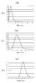
도2a 내지 도2c는 본 발명에 채용된 청색, 녹색, 적색 형광체의 근자외선에 대한 발광파장을 나타내는 그래프이다.2A to 2C are graphs showing light emission wavelengths of near ultraviolet rays of blue, green and red phosphors employed in the present invention.
도2a 및 도2b는 본 발명에 따른 백색 발광 장치의 예를 나타내는 측단면도이다.2A and 2B are side cross-sectional views showing an example of a white light emitting device according to the present invention.
도4는 본 발명의 일 측면에 따른 형광체혼합물로 구현가능한 색범위를 나타내는 색도좌표계이다.Figure 4 is a chromaticity coordinate system showing a color range that can be implemented with a phosphor mixture according to an aspect of the present invention.
도5는 본 발명의 다른 측면에 따른 백색 형광체 혼합물의 색범위를 나타내는 색도좌표계이다.5 is a chromaticity coordinate system showing a color range of a white phosphor mixture according to another aspect of the present invention.
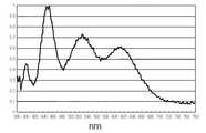
도6은 본 발명의 다른 측면에 따른 백색 형광체 혼합물에 의해 근자외선광이 변환된 백색광의 파장을 나타내는 그래프이다.6 is a graph showing wavelengths of white light converted from near-ultraviolet light by a white phosphor mixture according to another aspect of the present invention.
<도면의 주요부분에 대한 부호설명><Code Description of Main Parts of Drawing>
20,30: 백색발광장치22a,22b,32a,32b: 리드 프레임20,30: White
25,35; 근자외선 LED26a,26b,36a,36b: 와이어25,35; Near
28: 외형 몰딩부29,39: 파장변환부28:
31: 패키지 기판31: package substrate
본 발명은 파장변환용 형광체 혼합물에 관한 것으로서, 보다 상세하게는 다양한 색표현이 가능한 파장변환용 형광체 혼합물, 나아가 연색지수가 우수하여 자연광에 가까운 백색광을 제공할 수 있는 형광체 혼합물과 이를 이용한 백색 발광장치에 관한 것이다.The present invention relates to a phosphor mixture for wavelength conversion, and more particularly, a phosphor mixture for wavelength conversion capable of various color expressions, and a phosphor mixture capable of providing white light close to natural light with excellent color rendering index and a white light emitting device using the same. It is about.
일반적으로, 파장변환용 형광체물질은 다양한 광원의 특정 파장광을 원하는 파장광으로 변환시키는 물질로 사용되고 있다. 특히, 다양한 광원 중 발광다이오드는 저전력 구동 및 우수한 광효율으로 인해 LCD 백라이트와 자동차 조명 및 가정용 조명장치로서 유익하게 적용될 수 있으므로, 최근에 형광체 물질은 백색광 LED를 제조하기 위한 핵심기술로 각광받고 있다.In general, the phosphor material for wavelength conversion is used as a material for converting specific wavelength light of various light sources into the desired wavelength light. In particular, since light emitting diodes among various light sources can be advantageously applied as LCD backlights, automobile lights, and home lighting devices due to low power driving and excellent light efficiency, phosphor materials have recently been spotlighted as a core technology for manufacturing white light LEDs.
상기 백색광 발광장치는 대개 청색 LED에 황색 형광체를 도포하는 방식으로 제조되고 있다. 보다 구체적으로, GaN/InGaN 활성층을 갖는 청색 LED의 광방출면에 YAG(Y3Al5O12):Ce인 황색 형광체를 도포하여 청색광의 일부를 황색으로 변환시키고, 변환된 황색과 다른 일부의 청색광이 결합되어 백색광을 제공할 수 있다.The white light emitting device is usually manufactured by applying a yellow phosphor to a blue LED. More specifically, a yellow phosphor of YAG (Y3 Al5 O12 ): Ce is applied to the light emitting surface of the blue LED having the GaN / InGaN active layer to convert a part of the blue light to yellow, and to convert the part of the blue light to yellow. Blue light may be combined to provide white light.
상기한 YAG:Ce형광체(또는 TAG계 형광체)-청색LED로 구성된 종래의 백색발광장치는 낮은 연색성(color rendering)을 갖는다는 단점이 있다. 즉, 황색 형광체를 이용하여 얻어진 백색광의 파장은 도1에 도시된 그래프와 같이 청색과 황색에만 분포하고 있으므로 연색성이 낮아, 원하는 천연 백색광을 구현하는데 한계가 있다. 또한, 장시간 사용에 의해 작동온도가 증가되면, 황변현상(yellowing)이 발생되는 문제가 있다.The conventional white light emitting device composed of the above-described YAG: Ce phosphor (or TAG phosphor) -blue LED has a disadvantage of low color rendering. That is, since the wavelength of the white light obtained using the yellow phosphor is distributed only in blue and yellow as shown in the graph shown in FIG. 1, the color rendering is low, and thus there is a limit in implementing desired natural white light. In addition, when the operating temperature is increased by the use for a long time, there is a problem that yellowing occurs.
한편, 종래의 파장변환용 형광체물질은 특정 광원의 발광색과 특정 출력광의 색에 한정되어 제공되어 왔으며, 구현가능한 색분포도 매우 제한되므로, 사용자의 필요에 따라 다양한 광원의 발광색 및/또는 다양한 출력광의 색에 적용되는데 한계가 있다.On the other hand, the conventional wavelength conversion phosphor material has been provided limited to the light emission color of the specific light source and the color of the specific output light, and the color distribution that can be implemented is also very limited, so that the light emission color of the various light sources and / or the color of the various output light according to the user There is a limit to this.
이러한 문제를 해결하기 위해서, 최근에 본 출원인은, 대한민국 특허출원 2004-0076300호(2004.9.23일 출원)에서 3종의 특정 청색,녹색,적색 형광체의 혼합물를 제시한 바 있다.In order to solve this problem, the applicant has recently presented a mixture of three specific blue, green, and red phosphors in Korean Patent Application No. 2004-0076300 (filed September 23, 2004).
이와 같이, 당 기술분야에서는 황변현상을 완화시키는 동시에 연색지수(color rendering index: CRI)가 우수하고, 나아가, 폭넓은 색분포를 구현할 수 있 는 다양한 형광체 혼합물이 요구되어 왔다.As such, there is a need in the art for various phosphor mixtures to mitigate yellowing and to have excellent color rendering index (CRI), and to realize a wide color distribution.
본 발명은 상기한 종래 기술의 문제를 해결하기 위한 것으로서, 제1 목적은 다양한 색표현이 가능하도록 형광체 물질이 조합된 새로운 파장변환용 형광체 혼합물을 제공하는데 있다.The present invention is to solve the above-mentioned problems of the prior art, a first object is to provide a novel wavelength conversion phosphor mixture in which the phosphor material is combined to enable a variety of color expression.
또한, 본 발명의 제2 목적은 근자외선 LED에 적용되어 황변현상이 저감되고 우수한 연색지수를 갖는 백색광을 제공하기 위해서, 청색, 황색 및 적색 형광체물질이 혼합된 새로운 백색 발광 형광체 혼합물을 제공하는데 있다.In addition, a second object of the present invention is to provide a new white light emitting phosphor mixture in which blue, yellow and red phosphor materials are mixed in order to be applied to near-ultraviolet LED to reduce yellowing and provide white light having an excellent color rendering index. .
나아가, 본 발명의 제3 목적은 근자외선 LED에 상기한 백색 발광 형광체 혼합물이 적용된 우수한 특성의 백색 발광장치를 제공하는데 있다.Furthermore, a third object of the present invention is to provide a white light emitting device having excellent characteristics in which the white light emitting phosphor mixture is applied to a near ultraviolet LED.
상기한 기술적 과제를 달성하기 위해서, 본 발명의 제1 측면은 A5(PO4)3Cl:Eu2+, D2SiO4:Eu 및 MS:Eu인 3종의 형광체물질을 포함하고, 여기서, A는 Sr, Ca, Ba 및 Mg 중 적어도 하나의 원소이며, D는 Ba, Sr 및 Ca 중 적어도 하나의 원소이며, M는 Sr 및 Ca 중 적어도 하나의 원소인 파장변환용 형광체 혼합물을 제 공한다.In order to achieve the above technical problem, the first aspect of the present invention comprisesthree phosphor materials A5 (PO4 )3 Cl: Eu2+ , D2 SiO4 : Eu and MS: Eu, wherein , A is at least one element of Sr, Ca, Ba and Mg, D is at least one element of Ba, Sr and Ca, and M is at least one element of Sr and Ca to provide a phosphor mixture for wavelength conversion do.
본 발명의 제2 측면은, 근자외선 파장광을 CIE 색도좌표가 0.25≤x≤0.45와 0.25≤y≤0.43을 만족하는 색좌표 (x, y)에 위치하는 출력광으로 변환시키는 배합비로, A5(PO4)3Cl:Eu2+, D2SiO4:Eu 및 MS:Eu인 3종의 형광체물질을 혼합하여 이루어지며, 여기서, A는 Sr, Ca, Ba 및 Mg 중 적어도 하나의 원소이며, D는 Ba, Sr 및 Ca 중 적어도 하나의 원소이며, M는 Sr 및 Ca 중 적어도 하나의 원소인 백색 형광체 혼합물을 제공한다.A second aspect of the present invention, a near-ultraviolet light having a wavelength in the compounding ratio of the CIE chromaticity coordinates are converted to the output light which is located in the color coordinate (x, y) satisfying 0.25≤x≤0.45 and 0.25≤y≤0.43, A5 (PO4 )3 Cl: Eu2+ , D2 SiO4 : Eu and MS: Eu It is made by mixing three kinds of phosphor material, wherein A is at least one element of Sr, Ca, Ba and Mg. , D is at least one element of Ba, Sr and Ca, and M is at least one element of Sr and Ca to provide a white phosphor mixture.
또한, 본 발명의 제3 측면은, 근자외선 발광다이오드와, 상기 발광다이오드의 광방출방향에 형성되며, CIE 색도좌표가 0.25≤x≤0.45와 0.25≤y≤0.43을 만족하는 색좌표 (x, y)에 위치하며, A5(PO4)3Cl:Eu2+, D2SiO4:Eu 및 MS:Eu인 3종의 형광체물질을 포함하고, 여기서, A는 Sr, Ca, Ba 및 Mg 중 적어도 하나의 원소이며, D는 Ba, Sr 및 Ca 중 적어도 하나의 원소이며, M는 Sr 및 Ca 중 적어도 하나의 원소인 백색 형광체 혼합물과 경화성 수지로 이루어진 파장변환부를 포함하는 백색 발광장치를 제공한다. ,In addition, a third aspect of the present invention is a near-ultraviolet light-emitting diode and a color coordinate (x, y that is formed in the light emitting direction of the light-emitting diode, and the CIE chromaticity coordinates satisfy 0.25≤x≤0.45 and 0.25≤y≤0.43. ) Andthree phosphors A5 (PO4 )3 Cl: Eu2+ , D2 SiO4 : Eu and MS: Eu, wherein A is one of Sr, Ca, Ba and Mg It provides at least one element, D is at least one element of Ba, Sr and Ca, M is at least one element of Sr and Ca provides a white light emitting device comprising a wavelength conversion unit consisting of a white phosphor mixture and a curable resin. . ,
바람직하게, 상기 근자외선 발광다이오드의 광파장은 300∼450 ㎚일 수 있다. 또한, 특정 실시형태에서 상기 경화성 수지는 실리콘 또는 에폭시 수지일 수 있다.Preferably, the light wavelength of the near ultraviolet light emitting diode may be 300 to 450 nm. In addition, in certain embodiments the curable resin may be a silicone or epoxy resin.
바람직하게는, 상기 백색 발광장치의 출력광은 자연광에 가까운 80이상, 보다 바람직하게는 90%의 연색지수를 가질 수 있다.Preferably, the output light of the white light emitting device may have a color rendering index of 80 or more, more preferably 90% close to natural light.
본 명세서에서 사용되는 "근자외선"이라는 용어는 특별한 기재가 없는 한 300∼450㎚범위를 말한다. 형광체 또는 형광체 혼합물의 색도좌표 및 연색지수을 설명할 때에, 특별한 기재가 없는 한 근자외선광이 상기 형광체 또는 형광체 혼합물에 의해 변환된 출력광에 대한 색도좌표 및 연색지수를 말하는 것으로 이해될 수 있다. 또한, "백색 형광체 혼합물"이라 함은 특정 광(예, 근자외선광)을 백색광으로 여기시키는 형광체 혼합물을 말한다.The term "near ultraviolet" as used herein refers to a range of 300 to 450 nm unless otherwise specified. In describing the chromaticity coordinates and the color rendering index of the phosphor or the phosphor mixture, it can be understood that near ultraviolet light refers to the chromaticity coordinates and the color rendering index for the output light converted by the phosphor or the phosphor mixture unless otherwise specified. In addition, the term "white phosphor mixture" refers to a phosphor mixture that excites specific light (eg, near ultraviolet light) into white light.
이하, 첨부된 도면을 참조하여, 본 발명을 보다 상세히 설명하기로 한다.Hereinafter, with reference to the accompanying drawings, the present invention will be described in more detail.
본 발명에 따른 파장변환용 형광체는 다양한 색표현이 가능하도록 적절한 적색, 녹색 및 청색 형광체를 조합하여 얻어진다. 도2a 내지 도2c는 본 발명에 채용된 청색, 녹색, 적색 형광체의 근자외선에 대한 발광파장을 나타내는 그래프이다.The wavelength conversion phosphor according to the present invention is obtained by combining appropriate red, green and blue phosphors to enable various color expressions. 2A to 2C are graphs showing light emission wavelengths of near ultraviolet rays of blue, green and red phosphors employed in the present invention.
본 발명에 채용되는 청색형광체는 A5(PO4)3Cl:Eu2+이며, 여기서 A는 Sr, Ca, Ba 및 Mg 중 적어도 하나의 원소이다. 상기 청색형광체는 430∼460㎚의 피크파장을 갖는다. 예를 들어, (Sr,Ca)5(PO4)3Cl:Eu2+의 피크파장은 도2a에 도시된 바와 같이 약 450㎚을 갖는다.The blue phosphor employed in the present invention is A5 (PO4 )3 Cl: Eu2+ , where A is at least one element of Sr, Ca, Ba and Mg. The blue phosphor has a peak wavelength of 430-460 nm. For example, the peak wavelength of (Sr, Ca)5 (PO4 )3 Cl: Eu2+ has about 450 nm, as shown in FIG. 2A.
본 발명에 채용되는 녹색 형광체는 D2SiO4:Eu로서, 여기서 Ba, Sr 및 Ca 중 적어도 하나의 원소이다. 상기 녹색 형광체는 490∼525㎚의 피크파장을 갖는다. 예를 들어, (Ba,Sr)2SiO4:Eu의 피크파장은 도2b에 도시된 바와 같이 약 514㎚을 갖는다.The green phosphor employed in the present invention is D2 SiO4 : Eu, wherein at least one element of Ba, Sr and Ca is used. The green phosphor has a peak wavelength of 490-525 nm. For example, the peak wavelength of (Ba, Sr)2 SiO4 : Eu has about 514 nm, as shown in FIG. 2B.
적색 형광체는 MS:Eu이며, 여기서, M는 Sr 및 Ca 중 적어도 하나의 원소이다. 여기서 Sr 및 Ca 중 적어도 하나의 원소이다. 상기 적색 형광체는 585∼615㎚의 피크파장을 갖는다. 예를 들어, (Sr,Ca)S:Eu의 피크파장은 도2c에 도시된 바와 같이 약 602㎚을 갖는다.The red phosphor is MS: Eu, where M is at least one element of Sr and Ca. Wherein at least one of Sr and Ca is an element. The red phosphor has a peak wavelength of 585 to 615 nm. For example, the peak wavelength of (Sr, Ca) S: Eu has about 602 nm as shown in FIG. 2C.
본 발명의 제1 측면에 따르면, 상기한 청색, 녹색 및 적색인 3종의 형광체물질을 조합하여 색을 폭넓은 색도범위를 구현할 수 있다.According to the first aspect of the present invention, a combination of the three kinds of phosphor materials of blue, green, and red described above can implement a wide chromaticity range of colors.
아래의 제1 실시예에서 확인되는 바와 같이, 근자외선광원을 사용할 경우에 본 발명에 따른 형광체 혼합물로 구현가능한 색범위는 CIE 색도좌표에서 (0.15, 0.03), (0.19, 0.63) 및 (062, 0.37)을 꼭지점으로 갖는 좌표 상의 삼각형영역 내에 위치하는 것으로 정의될 수 있다(도3 참조).As can be seen in the first embodiment below, the color ranges that can be realized by the phosphor mixture according to the present invention when using a near ultraviolet light source are (0.15, 0.03), (0.19, 0.63) and (062, 0.37) may be defined as being located in a triangular region on a coordinate having a vertex (see FIG. 3).
이러한 색범위는 종래의 단색 형광체 또는 2개의 형광체물질의 조합에서는 구현하기 어려운 색도범위였으나, 본 발명에 따른 파장변환용 형광체 혼합물은 적 절한 배합비로서 상기한 다양한 색범위를 효과적으로 구현할 수 있다.This color range was a chromaticity range that is difficult to implement in the conventional monochromatic phosphor or a combination of two phosphor materials, the wavelength mixture phosphor mixture according to the present invention can effectively implement the above-mentioned various color ranges with an appropriate compounding ratio.
또한, 본 발명에 따른 파장변환용 형광체 혼합물은 특정 배합비에서 근자외선광(약 300㎚∼약 450㎚)을 우수한 특성을 갖는 백색광으로 변환시킬 수 있는 백색 형광체 혼합물을 제공한다.In addition, the phosphor mixture for wavelength conversion according to the present invention provides a white phosphor mixture capable of converting near-ultraviolet light (about 300 nm to about 450 nm) into white light having excellent characteristics at a specific compounding ratio.
상기 백색 형광체 혼합물은 바람직하게 근자외선광에 대한 출력광의 연색지수(CRI)를 향상시킬 수 있다. 상기 연색지수는 바람직하게는 80이상, 보다 바람직하게 90이상, 가장 바람직하게 95까지 높힐 수 있다. 또한, 황변현상을 탁월하게 저감시킬 수 있다.The white phosphor mixture may preferably improve the color rendering index (CRI) of the output light to near ultraviolet light. The color rendering index is preferably 80 or more, more preferably 90 or more, most preferably to 95. In addition, the yellowing phenomenon can be excellently reduced.
이러한 연색지수를 만족하는 형광체 혼합물의 배합비는 전체 중량을 기준으로 A5(PO4)3Cl:Eu2+는 40∼88wt%이고, D2SiO4:Eu는 10∼58wt%이며, MS:Eu는 2∼50wt%인 것이 바람직하며, 전체 중량을 기준으로 A5(PO4)3Cl:Eu2+는 70∼83wt%이고, D2SiO4:Eu는 13∼27wt%이며, MS:Eu는 3∼7wt%인 것이 보다 바람직하다.The compounding ratio of the phosphor mixture satisfying the color rendering index is 40 to 88 wt% of A5 (PO4 )3 Cl: Eu2+ based on the total weight, D2 SiO4 : Eu is 10 to 58 wt%, and MS: It is preferable that Eu is 2 to 50 wt%, A5 (PO4 )3 Cl: Eu2+ is 70 to 83 wt%, D2 SiO4 : Eu is 13 to 27 wt%, based on the total weight. As for Eu, it is more preferable that it is 3-7 wt%.
본 발명에 따른 백색 형광체 혼합물은 YAG계 형광체-청색 LED와 달리 근자외선광과 함께 구현될 수 있으며, 종래의 형광체와 달리, 황변현상과 같은 작동시간에 따른 색변현상을 최소화시킬 수 있다는 장점이 있다.Unlike the YAG-based phosphor-blue LED, the white phosphor mixture according to the present invention may be implemented with near-ultraviolet light, and unlike the conventional phosphor, there is an advantage of minimizing color change due to operating time such as yellowing. .
상기한 배합비는 특정 형광체에서는 백색 형광체 혼합물을 한정하는 범위로 활용될 수 있으나, 다양한 제조공정 또는 조성범위에 따라 비교적 큰 형광체 효율 의 차이(±100%)가 있을 수 있으며, 패키지구조 등에 따라 상기 조성범위는 실제 차이가 있을 수 있다.The above compounding ratio may be utilized in a range of limiting the white phosphor mixture in a particular phosphor, there may be a relatively large difference in phosphor efficiency (± 100%) according to various manufacturing processes or composition range, the composition according to the package structure, etc. The range may differ in practice.
상기한 백색 형광체 혼합물의 적절한 배합비와 연색지수 등의 개선효과는 아래의 제2 실시예에서 보다 상세히 설명하기로 한다.The improvement effect of the appropriate mixing ratio and the color rendering index of the white phosphor mixture will be described in more detail in the second embodiment below.
본 발명의 제3 측면에 따르면, 상기한 백색 형광체 혼합물과 근자외선 LED를 결합하여 우수한 조명기구로 사용될 수 있는 백색 발광장치가 제공될 수 있다. 이러한 백색 발광장치를 다양한 형태로 구현될 수 있으며, 도2a 및 도2b에 본 발명에 따른 백색 발광장치가 예시되어 있다.According to the third aspect of the present invention, a white light-emitting device which can be used as an excellent luminaire by combining the white phosphor mixture and the near-ultraviolet LED can be provided. The white light emitting device may be implemented in various forms, and the white light emitting device according to the present invention is illustrated in FIGS. 2A and 2B.
도3a에 도시된 백색 발광장치(20)는 외형몰딩부(28)와 2개의 리드프레임(22a,22b)을 포함할 수 있다. 일측 리드프레임(22a)은 컵구조를 형성된 일단을 가지며, 근자외선 LED(25)는 그 컵구조부에 실장된다. 상기 근자외선 발광다이오드(25)의 두 전극(미도시)은 각각 와이어(26a,26b)를 통해 상기 리드프레임(22a,22b)에 연결된다. 또한, 상기 LED(25)가 실장된 컵구조 상에 상기한 백색 형광체 혼합물과 경화성 수지를 포함한 파장변환부(29)가 제공된다. 상기 경화성 수지로는, 에폭시 수지, 실리콘 수지 또는 실리콘에폭시 혼합수지가 사용될 수 있다.The white
도3b에 도시된 백색 발광장치(30)는, 2개의 리드프레임(32a,32b)이 형성된 기판(31)을 포함한다. 상기 기판(31) 상에 근자외선 발광다이오드(35)가 배치되며. 상기 근자외선 발광다이오드(35)의 두 전극(미도시)은 각각 와이어(36a,36b)를 통해 상기 리드프레임(32a,32b)에 연결된다. 또한, 상기한 백색발광용 형광체 혼합물을 이용하여 상기 발광다이오드(35)를 둘러싸도록 파장변환부(39)가 형성된다. 상기 파장변환부(39)는 상기한 백색 형광체 혼합물뿐만 아니라, 에폭시 수지, 실리콘 수지 또는 실리콘에폭시 혼합수지를 적절하게 혼합하여 사용된다. 또한, 상기 파장변환부(39)의 형성공정은 당업자에게 자명한 바와 같이, 트랜스퍼 몰딩과 같은 몰딩공정을 통해 용이하게 구현될 수 있다.The white
상술된 백색발광장치(20,30)에 사용되는 근자외선 발광다이오드(25,35)는 300∼450㎚의 파장광을 방출하는 발광다이오드일 수 있다. 상기 파장변환부(29,39)는 상기한 백색발광용 형광체 혼합물에 의해 상기 LED(25,35)로부터 방출된 근자외선광을 황변현상이 저감되고 우수한 연색성을 갖는 백색광으로 변환시킬 수 있다.The near ultraviolet
이하, 본 발명의 구체적인 실시예를 통해 그 작용과 효과에 대해서 보다 상세히 설명한다.Hereinafter, the operation and effects will be described in more detail with reference to specific embodiments of the present invention.
(실시예 1)(Example 1)
본 실시예는 본 발명에 따른 파장변환용 형광체 혼합물을 통해 구현가능한 색도좌표범위를 확인하기 위해서 실시되었다.This embodiment was carried out to check the chromaticity coordinate range that can be implemented through the wavelength conversion phosphor mixture according to the present invention.
우선, 본 실시예에서 사용될 파장변환용 형광체 혼합물을 제조하기 위해서, 청색, 녹색 및 적색 형광체로, 각각 (Sr,Ca)5(PO4)3Cl:Eu2+, (Ba,Sr)2SiO4:Eu 및, (Sr,Ca)S:Eu를 마련하였다.First, in order to prepare the wavelength conversion phosphor mixture to be used in this embodiment, blue, green and red phosphors were respectively (Sr, Ca)5 (PO4 )3 Cl: Eu2+ , (Ba, Sr)2 SiO4 : Eu and (Sr, Ca) S: Eu were prepared.
상기 각 형광체분말에 대해, 405㎚의 근자외선광으로부터 변환된 광의 색도를 측정하여 CIE 색도좌표계에 해당하는 좌표를 구하고, 각 좌표를 CIE 색도좌표계에 나타내었다. 그 결과 얻어진 각 샘플에 대한 색도좌표는 하기 표2와 같이 나타났으며, 도4의 색도좌표계에 도시할 수 있었다.For each of the phosphor powders, the chromaticity of the light converted from the near-ultraviolet light of 405 nm was measured to obtain coordinates corresponding to the CIE chromaticity coordinate system, and each coordinate was shown in the CIE chromaticity coordinate system. The chromaticity coordinates for each sample obtained as shown in the following Table 2, it could be shown in the chromaticity coordinate system of FIG.
상기 표1 함께 도4를 참조하면, 본 실시예에 따른 파장변환용 형광체는 CIE 색도좌표에서 (0.15, 0.03), (0.19, 0.33) 및 (0.62, 0.37)을 꼭지점으로 갖는 좌표 상의 삼각형영역 내에 위치하는 것으로 정의될 수 있다. 이와 같이, 본 발명의 파장변환용 형광체는 종래의 형광체물질에서 구현할 수 없던 광범위한 분포를 갖는 색도를 적절한 배합비를 통해 구현할 수 있다는 것을 확인할 수 있었다.Referring to FIG. 4 together with Table 1, the wavelength conversion phosphor according to the present embodiment is in a triangular region on the coordinates having (0.15, 0.03), (0.19, 0.33) and (0.62, 0.37) as vertices in the CIE chromaticity coordinates. Can be defined as being located. As described above, it was confirmed that the wavelength conversion phosphor of the present invention can realize chromaticity having a wide distribution which cannot be realized in the conventional phosphor material through an appropriate blending ratio.
(실시예 2)(Example 2)
본 실시예는 본 발명에 따른 백색 형광체 혼합물의 색도 및 백색 특성(황변현상 및 연색지수)를 확인하기 위해서 실시되었다.This example was carried out to check the chromaticity and white characteristics (yellowing and color rendering index) of the white phosphor mixture according to the present invention.
우선, 본 실시예에서 사용될 백색 형광체 혼합물을 제조하기 위해서, 제1 실시예와 같이, 청색, 녹색 및 적색 형광체로, 각각 (Sr,Ca)5(PO4)3Cl:Eu2+, (Ba,Sr)2SiO4:Eu 및, (Sr,Ca):Eu를 마련하였다.First, in order to prepare a white phosphor mixture to be used in this embodiment, as in the first embodiment, blue, green and red phosphors were respectively (Sr, Ca)5 (PO4 )3 Cl: Eu2+ , (Ba , Sr)2 SiO4 : Eu and (Sr, Ca): Eu were prepared.
이어, 상기 형광체의 조합을 통해 구현가능한 색범위를 살펴보기 위해서, 하기 표2와 같은 배합비로 7개의 샘플을 마련하였다.Subsequently, in order to examine a color range that can be realized through the combination of the phosphors, seven samples were prepared at a compounding ratio as shown in Table 2 below.
상기한 표2의 배합비로 제조된 각 형광체혼합물과 동일한 근자외선 LED(약 405㎚)를 이용하여 도3b와 같은 구조를 갖는 7개의 백색 발광장치(발명예1 내지 6, 비교예1)를 제조하였다.Seven white light emitting devices (Inventive Examples 1 to 6 and Comparative Example 1) having the structure as shown in FIG. 3B were manufactured using the same near-ultraviolet LEDs (about 405 nm) as the respective phosphor mixtures prepared at the mixing ratios of Table 2 above. It was.
한편, 종래 기술에 따라 황색형광체인 Tb3Al5O12와 청색 LED(약 468㎚)를 이용하여 실리콘수지 배합비와 패키지제조를 다른 조건으로 하여 3개의 백색 발광장치(비교예2 내지 4)를 제조하였다.Meanwhile, according to the prior art, three white light emitting devices (Comparative Examples 2 to 4) were fabricated using Tb3 Al5 O12 , which is a yellow phosphor, and a blue LED (about 468 nm) under different conditions of silicone resin compounding ratio and package manufacturing. Prepared.
다음으로, 각 백색 발광장치로부터 변환된 광의 색도를 각 샘플별로 조사하여 연색지수를 측정하였으며, 또한, 인가전압을 동일하게 적용하여 5시간동안 발광시킨 후에, 색도변화에 따라 황변현상의 여부를 검사하였다. 그 결과를 아래의 표3에 나타내었으며, 각 색도좌표를 도5에 도시하였다.Next, the color rendering index was measured by irradiating the chromaticity of the light converted from each white light emitting device for each sample. Also, after applying the same applied voltage and emitting the light for 5 hours, the yellowing phenomenon was examined according to the chromaticity change. It was. The results are shown in Table 3 below, and each chromaticity coordinate is shown in FIG.
상기한 표3과 같이, 비교예1을 제외한 발명예 1 내지 6 및 비교예 2 내지 4은 CIE 색도좌표가 0.25≤x≤0.45와 0.25≤y≤0.43을 만족하는 색좌표 (x, y)(도5에서 W로 표시된 점선박스)에 위치하는 출력광으로 변환시키는 것으로 나타났다. 즉, 청색, 녹색 적색 형광체가 적정한 배합비를 벗어난 비교예1의 경우에는 백색특성이 떨어지는 것으로 나타났다.As shown in Table 3, Inventive Examples 1 to 6 and Comparative Examples 2 to 4, except for Comparative Example 1, have color coordinates (x, y) where the CIE chromaticity coordinates satisfy 0.25≤x≤0.45 and 0.25≤y≤0.43 (Fig. It is shown that the light is converted into the output light located at the dotted line box marked W at 5). That is, in the case of Comparative Example 1 in which the blue, green and red phosphors deviated from the proper blending ratio, the white characteristics were inferior.
또한, 자연광에 가까운 특성을 결정하는 연색지수(CRI)에 있어서, 비교예 2 내지 4은 백색을 나타내더라도, 비교예1과 유사하게 CRI가 약 72∼78수준으로 낮게 나타났으며 황변현상도 다소 관찰되었다. 반면에, 발명예1 내지 6의 경우에, 80이상으로 나타났으며, 발명예1, 4 및 6의 경우에는 90이상의 높은 값을 나타냈다. 물론, 종래의 TAG계 황색 형광체에서 발생되던 황변현상과 같은 색도변화현상이 거의 나타나지 않았다.In addition, in the color rendering index (CRI), which determines the characteristics close to natural light, although the Comparative Examples 2 to 4 show white color, similarly to Comparative Example 1, the CRI was lowered to about 72 to 78 level and the yellowing phenomenon was somewhat different. Was observed. On the other hand, in the case of the invention examples 1 to 6, it appeared as 80 or more, and in the case of invention examples 1, 4 and 6 showed a high value of 90 or more. Of course, color change such as yellowing which occurred in the conventional TAG-based yellow phosphor was hardly observed.
특히, 발명예6의 경우에는 95%라는 높은 수준의 연색지수를 나타냈다. 발명예6에 따른 백색 출력광파장을 도6에 도시하였다.In particular, in the case of Inventive Example 6, a high color rendering index of 95% was shown. The white output light wavelength according to Inventive Example 6 is shown in FIG.
도6을 참조하면, 여기된 발광파장이 가시광의 전영역에 걸쳐 광범위하면서 비교적 균일하게 발광되는 것을 나타났다. 이러한 파장분포는 종래의 황색 형광체(YAG계) 및 청색 LED의 조합에 의한 결과(도1 참조)에 비교하면, 상당히 개선된 것을 확인할 수 있다.Referring to FIG. 6, it is shown that the excited light emission wavelength emits a wide range and relatively uniform light over the entire region of visible light. This wavelength distribution can be confirmed to be considerably improved compared to the result of the combination of the conventional yellow phosphor (YAG system) and the blue LED (see FIG. 1).
본 실시예에서 사용된 샘플의 배합비를 기초하여 적절한 백색 형광체 혼합물의 배합비를 정의할 수 있다.The blending ratio of the appropriate white phosphor mixture can be defined based on the blending ratio of the samples used in this example.
바람직한 형광체 혼합물의 배합비는 전체 중량을 기준으로 A5(PO4)3Cl:Eu2+는 40∼88wt%이고, D2SiO4:Eu는 10∼58wt%이며, MS:Eu는 2∼50wt%인 것으로 정의할 수 있다. 보다 바람직한 배합비는 전체 중량을 기준으로 A5(PO4)3Cl:Eu2+는 70∼83wt%이고, D2SiO4:Eu는 13∼27wt%이며, MS:Eu는 3∼7wt%로 정의할 수 있다.Preferred compounding ratios for the mixture are 40 to 88 wt% of A5 (PO4 )3 Cl: Eu2+, 10 to 58 wt% of D2 SiO4 : Eu, and 2 to 50 wt% of MS: Eu, based on the total weight. Can be defined as%. A more preferable compounding ratio is 70 to 83 wt% of A5 (PO4 )3 Cl: Eu2+ based on the total weight, 13 to 27 wt% of D2 SiO4 : Eu, and 3 to 7 wt% of MS: Eu. Can be defined
이 경우에, 앞서 설명한 바와 같이, 통상적인 형광체물질의 효율과 근자외선광의 파장범위 및 조성범위와, 패키지구조와 같은 외부변수를 고려해야 하므로, 실제 형광체 혼합물의 배합비는 보다 넓게 설정될 수 있다.In this case, as described above, since the efficiency of the conventional phosphor material, the wavelength range and composition range of the near ultraviolet light, and external variables such as the package structure should be taken into consideration, the compounding ratio of the actual phosphor mixture can be set wider.
본 발명은 상술한 실시형태 및 첨부된 도면에 의해 한정되는 것이 아니며, 첨부된 청구범위에 의해 한정하고자 한다. 따라서, 청구범위에 기재된 본 발명의 기술적 사상을 벗어나지 않는 범위 내에서 당 기술분야의 통상의 지식을 가진 자에 의해 다양한 형태의 치환, 변형 및 변경이 가능할 것이며, 이 또한 본 발명의 범위에 속한다고 할 것이다.It is intended that the invention not be limited by the foregoing embodiments and the accompanying drawings, but rather by the claims appended hereto. Accordingly, various forms of substitution, modification, and alteration may be made by those skilled in the art without departing from the technical spirit of the present invention described in the claims, which are also within the scope of the present invention. something to do.
상술한 바와 같이, 본 발명에 따르면, 특정의 청색, 녹색, 적색의 형광체를 배합함으로써 넓은 색표현이 가능한 파장변환용 형광체 혼합물을 제공할 수 있으며, 또한 이를 적절한 배합비로서 백색 형광체 혼합물로 구현함으로써, 황변현상과 같은 색변화현상을 최소화하고, 연색지수가 우수한 천연 백색을 제공할 수 있다. 나아가, 본 발명은 상기한 백색발광용 형광체 혼합물과 근자외선 LED를 이용하여 우수한 백색광을 출력하는 발광장치를 제공할 수 있다.As described above, according to the present invention, by mixing a specific blue, green, and red phosphor, it is possible to provide a wavelength mixture phosphor capable of expressing a wide color, and by implementing this as a white phosphor mixture as an appropriate blending ratio, It can minimize color change such as yellowing and provide natural white with excellent color rendering index. Furthermore, the present invention can provide a light emitting device that outputs excellent white light by using the white light emitting phosphor mixture and the near-ultraviolet LED.
Claims (16)
Translated fromKoreanPriority Applications (6)
| Application Number | Priority Date | Filing Date | Title |
|---|---|---|---|
| KR1020050026708AKR100799839B1 (en) | 2005-03-30 | 2005-03-30 | Phosphor mixture for wavelength conversion and white light emitting device using the same |
| US11/320,137US7911127B2 (en) | 2005-03-30 | 2005-12-28 | Phosphor blend for wavelength conversion and white light emitting device using the same |
| DE102006001399ADE102006001399B4 (en) | 2005-03-30 | 2006-01-11 | Wavelength conversion phosphor white phosphor and white light emitting diode for which it is used |
| CNB2006100019018ACN100516168C (en) | 2005-03-30 | 2006-01-19 | Phosphor mixture and white light emitting device for wavelength conversion |
| JP2006013071AJP4310315B2 (en) | 2005-03-30 | 2006-01-20 | Phosphor mixture for wavelength conversion and white light emitting device using the same |
| TW095103413ATWI324174B (en) | 2005-03-30 | 2006-01-27 | Phosphor blend for wavelength conversion and white light emitting device using the same |
Applications Claiming Priority (1)
| Application Number | Priority Date | Filing Date | Title |
|---|---|---|---|
| KR1020050026708AKR100799839B1 (en) | 2005-03-30 | 2005-03-30 | Phosphor mixture for wavelength conversion and white light emitting device using the same |
Publications (2)
| Publication Number | Publication Date |
|---|---|
| KR20060104492A KR20060104492A (en) | 2006-10-09 |
| KR100799839B1true KR100799839B1 (en) | 2008-01-31 |
Family
ID=36999077
Family Applications (1)
| Application Number | Title | Priority Date | Filing Date |
|---|---|---|---|
| KR1020050026708AExpired - LifetimeKR100799839B1 (en) | 2005-03-30 | 2005-03-30 | Phosphor mixture for wavelength conversion and white light emitting device using the same |
Country Status (6)
| Country | Link |
|---|---|
| US (1) | US7911127B2 (en) |
| JP (1) | JP4310315B2 (en) |
| KR (1) | KR100799839B1 (en) |
| CN (1) | CN100516168C (en) |
| DE (1) | DE102006001399B4 (en) |
| TW (1) | TWI324174B (en) |
Cited By (1)
| Publication number | Priority date | Publication date | Assignee | Title |
|---|---|---|---|---|
| KR101607400B1 (en) | 2014-10-29 | 2016-03-29 | 엘지전자 주식회사 | Light emitting device |
Families Citing this family (16)
| Publication number | Priority date | Publication date | Assignee | Title |
|---|---|---|---|---|
| US9084328B2 (en) | 2006-12-01 | 2015-07-14 | Cree, Inc. | Lighting device and lighting method |
| US8513875B2 (en) | 2006-04-18 | 2013-08-20 | Cree, Inc. | Lighting device and lighting method |
| US9441793B2 (en) | 2006-12-01 | 2016-09-13 | Cree, Inc. | High efficiency lighting device including one or more solid state light emitters, and method of lighting |
| KR100946015B1 (en)* | 2007-01-02 | 2010-03-09 | 삼성전기주식회사 | White light emitting device and light source module for LCD backlight using the same |
| KR100862446B1 (en)* | 2007-01-26 | 2008-10-08 | 삼성전기주식회사 | White LED Light Source Module |
| US7568815B2 (en)* | 2007-03-26 | 2009-08-04 | Avago Technologies Ecbu Ip (Singapore) Pte. Ltd. | Light source having a plurality of white LEDs with different output spectra |
| US7744243B2 (en)* | 2007-05-08 | 2010-06-29 | Cree Led Lighting Solutions, Inc. | Lighting device and lighting method |
| JP2010527510A (en)* | 2007-05-08 | 2010-08-12 | クリー エル イー ディー ライティング ソリューションズ インコーポレイテッド | Lighting device and lighting method |
| EP2015614B1 (en)* | 2007-07-12 | 2010-12-15 | Koito Manufacturing Co., Ltd. | Light emitting device |
| US20100232135A1 (en)* | 2007-11-23 | 2010-09-16 | Kawamura Munehiro | Photosynthesis inhibiting light source and illuminating device that uses the same |
| JP5444619B2 (en) | 2008-02-07 | 2014-03-19 | 株式会社ジェイテクト | Multi-layer circuit board and motor drive circuit board |
| US20100290230A1 (en)* | 2009-05-15 | 2010-11-18 | Dirk Carl W | Protective Light Filters and Illuminants Having Customized Spectral Profiles |
| FI20095967L (en)* | 2009-09-18 | 2011-03-19 | Valoya Oy | Lighting arrangement |
| EP2516256B1 (en)* | 2009-12-22 | 2017-11-22 | Tufts University | Inflatable and rigidizable support element |
| EP2962530B1 (en) | 2013-02-28 | 2017-05-03 | Vilnius University | Solid-state sources of light for preferential colour rendition |
| WO2018013905A2 (en) | 2016-07-14 | 2018-01-18 | Helios Applied Science | Photoinitiation-based deployable structures |
Citations (2)
| Publication number | Priority date | Publication date | Assignee | Title |
|---|---|---|---|---|
| KR200360280Y1 (en)* | 2004-06-04 | 2004-08-25 | 안재현 | A descending device for escape |
| KR200369010Y1 (en)* | 2004-07-07 | 2004-12-03 | 최병수 | Yellow soil pad for roast food |
Family Cites Families (19)
| Publication number | Priority date | Publication date | Assignee | Title |
|---|---|---|---|---|
| JPS5241484A (en)* | 1975-09-25 | 1977-03-31 | Gen Electric | Fluorescent lamp structure using two kinds of phospher |
| US4423349A (en)* | 1980-07-16 | 1983-12-27 | Nichia Denshi Kagaku Co., Ltd. | Green fluorescence-emitting material and a fluorescent lamp provided therewith |
| AT410266B (en)* | 2000-12-28 | 2003-03-25 | Tridonic Optoelectronics Gmbh | LIGHT SOURCE WITH A LIGHT-EMITTING ELEMENT |
| DE10129464A1 (en)* | 2001-06-19 | 2003-01-02 | Philips Corp Intellectual Pty | Low pressure gas discharge lamp with mercury-free gas filling |
| KR100894372B1 (en) | 2001-10-01 | 2009-04-22 | 파나소닉 주식회사 | Semiconductor light emitting device and light emitting device using same |
| JP3985486B2 (en) | 2001-10-01 | 2007-10-03 | 松下電器産業株式会社 | Semiconductor light emitting element and light emitting device using the same |
| TW518773B (en) | 2001-12-31 | 2003-01-21 | Solidlite Corp | Manufacturing method of white LED |
| KR100497339B1 (en) | 2002-01-08 | 2005-06-23 | 주식회사 이츠웰 | Light emitting diode device and illuminator, display, and back light using the same |
| JP4191937B2 (en) | 2002-02-15 | 2008-12-03 | 株式会社日立製作所 | White light source and image display apparatus using the same |
| AU2003215785A1 (en) | 2002-03-25 | 2003-10-08 | Philips Intellectual Property And Standards Gmbh | Tri-color white light led lamp |
| US20060093852A1 (en)* | 2002-06-04 | 2006-05-04 | Dirk Marsitzky | Phosphorescent and luminescent conjugated polymers and their use in electroluminescent assemblies |
| US6809471B2 (en) | 2002-06-28 | 2004-10-26 | General Electric Company | Phosphors containing oxides of alkaline-earth and Group-IIIB metals and light sources incorporating the same |
| US6809781B2 (en) | 2002-09-24 | 2004-10-26 | General Electric Company | Phosphor blends and backlight sources for liquid crystal displays |
| KR20040076300A (en) | 2003-02-25 | 2004-09-01 | 주식회사 하이닉스반도체 | Method of forming a metal wiring in a semiconductor device |
| US7723740B2 (en)* | 2003-09-18 | 2010-05-25 | Nichia Corporation | Light emitting device |
| US7488432B2 (en)* | 2003-10-28 | 2009-02-10 | Nichia Corporation | Fluorescent material and light-emitting device |
| US7229573B2 (en)* | 2004-04-20 | 2007-06-12 | Gelcore, Llc | Ce3+ and Eu2+ doped phosphors for light generation |
| WO2005124878A1 (en)* | 2004-06-22 | 2005-12-29 | Konica Minolta Holdings, Inc. | White light-emitting diode and method for producing same |
| US7443094B2 (en)* | 2005-03-31 | 2008-10-28 | Dowa Electronics Materials Co., Ltd. | Phosphor and manufacturing method of the same, and light emitting device using the phosphor |
- 2005
- 2005-03-30KRKR1020050026708Apatent/KR100799839B1/ennot_activeExpired - Lifetime
- 2005-12-28USUS11/320,137patent/US7911127B2/enactiveActive
- 2006
- 2006-01-11DEDE102006001399Apatent/DE102006001399B4/enactiveActive
- 2006-01-19CNCNB2006100019018Apatent/CN100516168C/enactiveActive
- 2006-01-20JPJP2006013071Apatent/JP4310315B2/enactiveActive
- 2006-01-27TWTW095103413Apatent/TWI324174B/enactive
Patent Citations (2)
| Publication number | Priority date | Publication date | Assignee | Title |
|---|---|---|---|---|
| KR200360280Y1 (en)* | 2004-06-04 | 2004-08-25 | 안재현 | A descending device for escape |
| KR200369010Y1 (en)* | 2004-07-07 | 2004-12-03 | 최병수 | Yellow soil pad for roast food |
Cited By (2)
| Publication number | Priority date | Publication date | Assignee | Title |
|---|---|---|---|---|
| KR101607400B1 (en) | 2014-10-29 | 2016-03-29 | 엘지전자 주식회사 | Light emitting device |
| US9518719B2 (en) | 2014-10-29 | 2016-12-13 | Lg Electronics Inc. | Light emitting device |
Also Published As
| Publication number | Publication date |
|---|---|
| US7911127B2 (en) | 2011-03-22 |
| TW200634130A (en) | 2006-10-01 |
| DE102006001399A1 (en) | 2006-10-05 |
| TWI324174B (en) | 2010-05-01 |
| JP2006282994A (en) | 2006-10-19 |
| JP4310315B2 (en) | 2009-08-05 |
| US20060221635A1 (en) | 2006-10-05 |
| CN1840611A (en) | 2006-10-04 |
| DE102006001399B4 (en) | 2013-03-14 |
| CN100516168C (en) | 2009-07-22 |
| KR20060104492A (en) | 2006-10-09 |
Similar Documents
| Publication | Publication Date | Title |
|---|---|---|
| JP4310315B2 (en) | Phosphor mixture for wavelength conversion and white light emitting device using the same | |
| CN101184823B (en) | Lighting system comprising luminescent material compensating for color defects | |
| KR100862695B1 (en) | White light emitting diode | |
| KR101616013B1 (en) | Alpha-sialon phosphor | |
| EP1733441B1 (en) | Light emitting device and phosphor for the same | |
| US20170047488A1 (en) | Light emitting device | |
| JP2019054286A (en) | Light emitting device | |
| KR101220669B1 (en) | Phosphor and led lamp using the phosphor | |
| KR100638619B1 (en) | Phosphor mixture for wavelength conversion and white light emitting device using the same | |
| KR102503519B1 (en) | Oxyfluoride phosphor compositions and lighting apparatus thereof | |
| TWI354384B (en) | Light emitting device | |
| US20190097093A1 (en) | Light-emitting device | |
| KR101059119B1 (en) | High color rendering white light emitting diode | |
| KR20080072945A (en) | Phosphor and its manufacturing method | |
| KR100735287B1 (en) | Red light emitting phosphor and light emitting device | |
| JP2007197608A (en) | Phosphor and process for producing the same, and lamp | |
| CN101619136B (en) | Organic thin film and light-emitting diode chip packaging module for converting spectrum | |
| KR102092676B1 (en) | Light emitting device | |
| KR20100110646A (en) | Green light emitting phosphor and light emitting device | |
| KR101809098B1 (en) | Light emitting device | |
| KR101524946B1 (en) | White phosphor composition having high color rendering properties, and light emitting diode comprising the same | |
| KR101476217B1 (en) | Phosphor emitting yellow light and light emitting device package using the same |
Legal Events
| Date | Code | Title | Description |
|---|---|---|---|
| A201 | Request for examination | ||
| PA0109 | Patent application | Patent event code:PA01091R01D Comment text:Patent Application Patent event date:20050330 | |
| PA0201 | Request for examination | ||
| E902 | Notification of reason for refusal | ||
| PE0902 | Notice of grounds for rejection | Comment text:Notification of reason for refusal Patent event date:20060830 Patent event code:PE09021S01D | |
| PG1501 | Laying open of application | ||
| AMND | Amendment | ||
| E601 | Decision to refuse application | ||
| PE0601 | Decision on rejection of patent | Patent event date:20070111 Comment text:Decision to Refuse Application Patent event code:PE06012S01D Patent event date:20060830 Comment text:Notification of reason for refusal Patent event code:PE06011S01I | |
| J201 | Request for trial against refusal decision | ||
| PJ0201 | Trial against decision of rejection | Patent event date:20070209 Comment text:Request for Trial against Decision on Refusal Patent event code:PJ02012R01D Patent event date:20070111 Comment text:Decision to Refuse Application Patent event code:PJ02011S01I Appeal kind category:Appeal against decision to decline refusal Decision date:20071126 Appeal identifier:2007101001634 Request date:20070209 | |
| AMND | Amendment | ||
| PB0901 | Examination by re-examination before a trial | Comment text:Amendment to Specification, etc. Patent event date:20070312 Patent event code:PB09011R02I Comment text:Request for Trial against Decision on Refusal Patent event date:20070209 Patent event code:PB09011R01I Comment text:Amendment to Specification, etc. Patent event date:20061030 Patent event code:PB09011R02I | |
| B601 | Maintenance of original decision after re-examination before a trial | ||
| E801 | Decision on dismissal of amendment | ||
| PB0601 | Maintenance of original decision after re-examination before a trial | Comment text:Report of Result of Re-examination before a Trial Patent event code:PB06011S01D Patent event date:20070420 | |
| PE0801 | Dismissal of amendment | Patent event code:PE08012E01D Comment text:Decision on Dismissal of Amendment Patent event date:20070420 Patent event code:PE08011R01I Comment text:Amendment to Specification, etc. Patent event date:20070312 Patent event code:PE08011R01I Comment text:Amendment to Specification, etc. Patent event date:20061030 | |
| J301 | Trial decision | Free format text:TRIAL DECISION FOR APPEAL AGAINST DECISION TO DECLINE REFUSAL REQUESTED 20070209 Effective date:20071126 | |
| PJ1301 | Trial decision | Patent event code:PJ13011S01D Patent event date:20071126 Comment text:Trial Decision on Objection to Decision on Refusal Appeal kind category:Appeal against decision to decline refusal Request date:20070209 Decision date:20071126 Appeal identifier:2007101001634 | |
| PS0901 | Examination by remand of revocation | ||
| S901 | Examination by remand of revocation | ||
| GRNO | Decision to grant (after opposition) | ||
| PS0701 | Decision of registration after remand of revocation | Patent event date:20071227 Patent event code:PS07012S01D Comment text:Decision to Grant Registration Patent event date:20071127 Patent event code:PS07011S01I Comment text:Notice of Trial Decision (Remand of Revocation) | |
| GRNT | Written decision to grant | ||
| PR0701 | Registration of establishment | Comment text:Registration of Establishment Patent event date:20080124 Patent event code:PR07011E01D | |
| PR1002 | Payment of registration fee | Payment date:20080124 End annual number:3 Start annual number:1 | |
| PG1601 | Publication of registration | ||
| PR1001 | Payment of annual fee | Payment date:20101215 Start annual number:4 End annual number:4 | |
| PR1001 | Payment of annual fee | Payment date:20120116 Start annual number:5 End annual number:5 | |
| FPAY | Annual fee payment | Payment date:20130102 Year of fee payment:6 | |
| PR1001 | Payment of annual fee | Payment date:20130102 Start annual number:6 End annual number:6 | |
| FPAY | Annual fee payment | Payment date:20140103 Year of fee payment:7 | |
| PR1001 | Payment of annual fee | Payment date:20140103 Start annual number:7 End annual number:7 | |
| FPAY | Annual fee payment | Payment date:20141231 Year of fee payment:8 | |
| PR1001 | Payment of annual fee | Payment date:20141231 Start annual number:8 End annual number:8 | |
| FPAY | Annual fee payment | Payment date:20160104 Year of fee payment:9 | |
| PR1001 | Payment of annual fee | Payment date:20160104 Start annual number:9 End annual number:9 | |
| FPAY | Annual fee payment | Payment date:20170102 Year of fee payment:10 | |
| PR1001 | Payment of annual fee | Payment date:20170102 Start annual number:10 End annual number:10 | |
| FPAY | Annual fee payment | Payment date:20191226 Year of fee payment:13 | |
| PR1001 | Payment of annual fee | Payment date:20191226 Start annual number:13 End annual number:13 | |
| PR1001 | Payment of annual fee | Payment date:20201230 Start annual number:14 End annual number:14 | |
| PR1001 | Payment of annual fee | Payment date:20221221 Start annual number:16 End annual number:16 | |
| PR1001 | Payment of annual fee | Payment date:20231226 Start annual number:17 End annual number:17 |