KR100792311B1 - Charging power supply, charging device, battery unit, contactless charging system and contactless charging method - Google Patents
Charging power supply, charging device, battery unit, contactless charging system and contactless charging methodDownload PDFInfo
- Publication number
- KR100792311B1 KR100792311B1KR1020050069962AKR20050069962AKR100792311B1KR 100792311 B1KR100792311 B1KR 100792311B1KR 1020050069962 AKR1020050069962 AKR 1020050069962AKR 20050069962 AKR20050069962 AKR 20050069962AKR 100792311 B1KR100792311 B1KR 100792311B1
- Authority
- KR
- South Korea
- Prior art keywords
- charging
- battery
- voltage
- pulse
- charge
- Prior art date
- Legal status (The legal status is an assumption and is not a legal conclusion. Google has not performed a legal analysis and makes no representation as to the accuracy of the status listed.)
- Expired - Lifetime
Links
Images


Classifications
- H—ELECTRICITY
- H02—GENERATION; CONVERSION OR DISTRIBUTION OF ELECTRIC POWER
- H02J—CIRCUIT ARRANGEMENTS OR SYSTEMS FOR SUPPLYING OR DISTRIBUTING ELECTRIC POWER; SYSTEMS FOR STORING ELECTRIC ENERGY
- H02J7/00—Circuit arrangements for charging or depolarising batteries or for supplying loads from batteries
- H02J7/0042—Circuit arrangements for charging or depolarising batteries or for supplying loads from batteries characterised by the mechanical construction
- H02J7/0044—Circuit arrangements for charging or depolarising batteries or for supplying loads from batteries characterised by the mechanical construction specially adapted for holding portable devices containing batteries
- H—ELECTRICITY
- H02—GENERATION; CONVERSION OR DISTRIBUTION OF ELECTRIC POWER
- H02J—CIRCUIT ARRANGEMENTS OR SYSTEMS FOR SUPPLYING OR DISTRIBUTING ELECTRIC POWER; SYSTEMS FOR STORING ELECTRIC ENERGY
- H02J50/00—Circuit arrangements or systems for wireless supply or distribution of electric power
- H02J50/10—Circuit arrangements or systems for wireless supply or distribution of electric power using inductive coupling
- H—ELECTRICITY
- H02—GENERATION; CONVERSION OR DISTRIBUTION OF ELECTRIC POWER
- H02J—CIRCUIT ARRANGEMENTS OR SYSTEMS FOR SUPPLYING OR DISTRIBUTING ELECTRIC POWER; SYSTEMS FOR STORING ELECTRIC ENERGY
- H02J50/00—Circuit arrangements or systems for wireless supply or distribution of electric power
- H02J50/80—Circuit arrangements or systems for wireless supply or distribution of electric power involving the exchange of data, concerning supply or distribution of electric power, between transmitting devices and receiving devices
- H—ELECTRICITY
- H02—GENERATION; CONVERSION OR DISTRIBUTION OF ELECTRIC POWER
- H02J—CIRCUIT ARRANGEMENTS OR SYSTEMS FOR SUPPLYING OR DISTRIBUTING ELECTRIC POWER; SYSTEMS FOR STORING ELECTRIC ENERGY
- H02J7/00—Circuit arrangements for charging or depolarising batteries or for supplying loads from batteries
- H02J7/0047—Circuit arrangements for charging or depolarising batteries or for supplying loads from batteries with monitoring or indicating devices or circuits
- H—ELECTRICITY
- H04—ELECTRIC COMMUNICATION TECHNIQUE
- H04B—TRANSMISSION
- H04B5/00—Near-field transmission systems, e.g. inductive or capacitive transmission systems
- H04B5/20—Near-field transmission systems, e.g. inductive or capacitive transmission systems characterised by the transmission technique; characterised by the transmission medium
- H04B5/24—Inductive coupling
- H—ELECTRICITY
- H04—ELECTRIC COMMUNICATION TECHNIQUE
- H04B—TRANSMISSION
- H04B5/00—Near-field transmission systems, e.g. inductive or capacitive transmission systems
- H04B5/70—Near-field transmission systems, e.g. inductive or capacitive transmission systems specially adapted for specific purposes
- H04B5/79—Near-field transmission systems, e.g. inductive or capacitive transmission systems specially adapted for specific purposes for data transfer in combination with power transfer
- H—ELECTRICITY
- H02—GENERATION; CONVERSION OR DISTRIBUTION OF ELECTRIC POWER
- H02J—CIRCUIT ARRANGEMENTS OR SYSTEMS FOR SUPPLYING OR DISTRIBUTING ELECTRIC POWER; SYSTEMS FOR STORING ELECTRIC ENERGY
- H02J2310/00—The network for supplying or distributing electric power characterised by its spatial reach or by the load
- H02J2310/10—The network having a local or delimited stationary reach
- H02J2310/20—The network being internal to a load
- H02J2310/22—The load being a portable electronic device
Landscapes
- Engineering & Computer Science (AREA)
- Power Engineering (AREA)
- Computer Networks & Wireless Communication (AREA)
- Signal Processing (AREA)
- Charge And Discharge Circuits For Batteries Or The Like (AREA)
- Secondary Cells (AREA)
Abstract
Translated fromKoreanDescription
Translated fromKorean본 명세서에 첨부되는 다음의 도면들은 본 발명의 바람직한 실시예를 예시하는 것이며, 후술하는 발명의 상세한 설명과 함께 본 발명의 기술 사상을 더욱 이해시키는 역할을 하는 것이므로, 본 발명은 그러한 도면에 기재된 사항에만 한정되어 해석되어서는 아니된다.The following drawings, which are attached to this specification, illustrate exemplary embodiments of the present invention, and together with the detailed description of the present invention, serve to further understand the technical spirit of the present invention. It should not be construed as limited to.
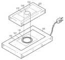
도 1은 본 발명의 바람직한 실시예에 따른 무접점 충전시스템의 개략 사시도이다.1 is a schematic perspective view of a contactless charging system according to a preferred embodiment of the present invention.
도 2는 본 발명의 바람직한 실시예에 따른 무접점 충전시스템의 내부 기능 블록도이다.2 is an internal functional block diagram of a contactless charging system according to a preferred embodiment of the present invention.
도 3은 충전시작 시점으로부터 만충전 시점까지의 전력 신호와 통신 신호의 시분할 배치를 설명하기 위한 타이밍 챠트이다.3 is a timing chart for explaining the time division arrangement of the power signal and the communication signal from the charging start time to the full charge time.
도 4는 본 발명에 따른 무접점 충전 방법의 절차를 설명하기 위한 플로우 챠트이다.4 is a flowchart illustrating a procedure of a contactless charging method according to the present invention.
<도면의 주요 참조 부호에 대한 설명><Description of Major Reference Marks in Drawing>
100: 충전 모체 200: 배터리 장치 100: charging matrix 200: battery unit
150: 충전전력 공급장치 250: 충전 장치 150: charging power supply 250: charging device
110: 1차 코일 210: 2차 코일 110: primary coil 210: secondary coil
120: 무선수신모듈 220: 무선송신모듈 120: wireless receiving module 220: wireless transmitting module
151: 상용 교류전원 153: 구동 회로 151: commercial AC power source 153: drive circuit
261: 보호 회로(PCM) 262: 배터리 261: protection circuit (PCM) 262: battery
본 발명은 휴대형 전자기기의 충전장치에 관한 것으로서, 특히 유도 결합을 이용한 무접점 충전시스템에 관한 것이다.The present invention relates to a charging device for a portable electronic device, and more particularly to a contactless charging system using an inductive coupling.
이동통신단말, PDA 등과 같은 휴대형 전자기기에는 재충전 가능한 2차전지(배터리)가 장착된다. 2차 전지(배터리)를 충전하기 위해서는 가정용 상용 전원을 이용하여 휴대형 전자기기의 배터리에 전기 에너지를 제공하는 별도의 충전장치가 필요하다. 통상적으로, 충전장치와 배터리에는 외부에 각각 별도의 접촉 단자가 구성되어 있어서, 두 접촉 단자를 서로 접속시키는 것에 의해 충전장치와 배터리를 전기적으로 연결한다.Portable electronic devices such as mobile communication terminals and PDAs are equipped with rechargeable secondary batteries (batteries). In order to charge a secondary battery (battery), a separate charging device for providing electrical energy to a battery of a portable electronic device using a commercial power source for home is needed. Typically, a separate contact terminal is configured on the outside of the charging device and the battery, thereby electrically connecting the charging device and the battery by connecting the two contact terminals to each other.
그러나, 이와 같이 접촉 단자가 외부에 돌출되면, 미관상 좋지 않고 접촉 단자가 외부의 이물질에 오염되어 접촉 상태가 쉽게 불량해지는 문제점이 있다. 또한, 사용자의 부주의로 배터리에 단락이 발생하거나 습기에 노출되면, 충전에너지가 쉽게 소실될 수 있다.However, when the contact terminal protrudes to the outside as described above, there is a problem in that the contact terminal is not good and the contact terminal is contaminated with external foreign matters so that the contact state is easily poor. In addition, when the battery is inadvertently shorted or exposed to moisture, the charging energy may be easily lost.
이러한 접촉식 충전방식의 문제점을 해결하기 위하여, 충전장치와 배터리를 비접촉 방식으로 충전하는 무선 충전 시스템이 제안되었다.In order to solve the problem of the contact charging method, a wireless charging system for charging the charging device and the battery in a non-contact method has been proposed.
대한민국 공개특허 제 2002-57468 호, 대한민국 공개특허 제 2002-57469 호, 대한민국 등록특허 제 363,439 호, 대한민국 등록특허 제 428,713 호, 대한민국 공개특허 제 2002-35242 호, 대한민국 등록실용신안 제 217,303 호, 영국 공개특허 제 2,314,470 호 및 미국 공개특허 제 2003/0,210,106 호는 충전모체의 1차 코일과 배터리팩의 2차 코일간의 유도 결합을 이용하여 접촉단자 없이 배터리를 충전시키는 비접촉식 충전시스템을 개시한다.Republic of Korea Patent Publication No. 2002-57468, Republic of Korea Patent Publication No. 2002-57469, Republic of Korea Patent No. 363,439, Republic of Korea Patent No. 428,713, Republic of Korea Patent No. 2002-35242, Republic of Korea Utility Model No. 217,303, United Kingdom US Patent Nos. 2,314,470 and US 2003 / 0,210,106 disclose a non-contact charging system for charging a battery without contact terminals by using an inductive coupling between a primary coil of a charging matrix and a secondary coil of a battery pack.
또한, 대한민국 공개특허공보 제 2004-87037 호는 배터리의 전압 및 전류를 측정하여 사용시간 및 충전용량 등의 정보를 누적하고, 이렇게 누적된 정보에 근거하여 배터리의 충,방전 용량을 보정하기 위한 제어회로를 포함하는 무접점 충전 배터리팩을 개시한다. 특히, 상기 제어회로는 배터리에서 검출되는 충전 전압과 온도센서부에서 검출되는 배터리의 온도에 근거하여 충전 전압과, 배터리 온도를 보상하는 보상회로를 더 포함하고 있다.In addition, Korean Patent Laid-Open Publication No. 2004-87037 accumulates information such as usage time and charge capacity by measuring voltage and current of a battery, and controls to correct charge and discharge capacity of the battery based on the accumulated information. A contactless rechargeable battery pack comprising a circuit is disclosed. In particular, the control circuit further includes a compensation circuit for compensating the charging voltage and the battery temperature based on the charging voltage detected by the battery and the temperature of the battery detected by the temperature sensor unit.
그러나, 상기 037'호 공개 특허는 배터리의 충전상태정보(충전 전류, 충전전압 등)를 피드백 받고, 이 충전상태정보에 대응하는 충전 전력을 생성하는 전력공급장치나 이를 이용한 무접점 충전 시스템을 개시하고 있지 않다.However, the 037 'publication patent discloses a power supply device or a contactless charging system using the same, which receives feedback of the charging state information (charge current, charging voltage, etc.) of the battery and generates charging power corresponding to the charging state information. I'm not doing it.
본 발명은 1차 코일과 2차 코일의 유도 결합을 이용한 무접점 충전시스템에 있어서, 무선으로 배터리의 상태정보를 피드백 받아 배터리의 상태에 가장 적합한 충전 전력을 생성하는 것을 목적으로 한다.The present invention provides a contactless charging system using an inductive coupling of a primary coil and a secondary coil, and aims to generate charging power most suitable for a state of a battery by receiving feedback of state information of the battery wirelessly.
또한, 본 발명은 1차 충전유닛(충전모체)과 2차 충전유닛(배터리팩) 사이의 전력 신호와 통신 신호간의 간섭 현상을 해소하는 것을 다른 목적으로 한다.In addition, another object of the present invention is to solve the interference phenomenon between the power signal and the communication signal between the primary charging unit (charging mother) and the secondary charging unit (battery pack).
또한, 본 발명은 불필요한 전력 소모가 방지될 수 있도록 1차 코일과 2차 코일이 자기적으로 완전히 결합된 후에 충전전력을 공급하는 것을 또 다른 목적으로 한다.In addition, another object of the present invention is to supply charging power after the primary coil and the secondary coil are magnetically completely coupled so that unnecessary power consumption can be prevented.
또한, 본 발명은 배터리의 충전 상태를 대기모드, 충전모드 및 완충모드로 나누고, 배터리의 모드 상태를 파악하여 각 모드에 가장 적합한 충전 전력을 공급하는 것을 또 다른 목적으로 한다.In another aspect, the present invention is to divide the state of charge of the battery into a standby mode, a charge mode and a buffer mode, to determine the mode state of the battery to provide the most suitable charging power for each mode.
본 발명의 다른 목적 및 장점들은 하기에 설명될 것이며, 본 발명의 실시예에 의해 알게 될 것이다. 또한, 본 발명의 목적 및 장점들은 첨부된 특허청구범위에 나타낸 수단 및 조합에 의해 실현될 수 있다.Other objects and advantages of the invention will be described below and will be appreciated by the embodiments of the invention. Furthermore, the objects and advantages of the present invention can be realized by means and combinations indicated in the appended claims.
상기와 같은 목적을 달성하기 위해, 본 발명의 제 1 양태는 유도 결합을 위한 2차 코일, 데이터를 무선 송신하기 위한 무선송신모듈, 배터리의 충전상태를 조절하는 충전제어회로 및 재충전 가능한 배터리를 포함하는 배터리장치와 무접점으로 결합되는 충전전력 공급장치에 관한 것이다.In order to achieve the above object, a first aspect of the present invention includes a secondary coil for inductive coupling, a wireless transmission module for wirelessly transmitting data, a charge control circuit for adjusting a state of charge of a battery, and a rechargeable battery. The present invention relates to a charging power supply unit coupled to a battery device without contact.
본 발명의 제 1 양태에 따른 상기 충전전력 공급장치는, 상기 2차 코일에 충전 전력을 유도하는 1차 코일; 상기 무선송신모듈로부터 충전상태정보를 수신하기 위한 무선수신모듈; 상기 1, 2차 코일 사이의 전력 신호와 상기 무선 송,수신 모듈 사이의 통신 신호가 서로 시간적으로 중첩되지 않도록 상기 1차 코일을 구동하는 수단을 포함한다.The charging power supply device according to the first aspect of the invention, the primary coil for inducing charging power to the secondary coil; A wireless reception module for receiving charge state information from the wireless transmission module; And means for driving the primary coil so that the power signal between the primary and secondary coils and the communication signal between the wireless transmission and reception modules do not overlap each other in time.
또한, 본 발명의 제 2 양태는, 상용 교류전압을 이용하여 상용 주파수 이상의 교류 전압 펄스를 생성하는 상기 충전전력 공급장치로부터 무접점으로 전력을 공급받고, 이 전력을 이용하여 재충전 가능한 배터리를 충전하는 장치에 관한 것이다.In addition, a second aspect of the present invention is to provide a contactless power supply from the charging power supply device for generating an AC voltage pulse of a commercial frequency or more using a commercial AC voltage, and to charge the rechargeable battery using this power. Relates to a device.
이 충전 장치는, 상기 충전전력 공급장치의 1차 코일과 자기적으로 결합되어 상기 교류 전압 펄스에 대응하는 유도 기전력 펄스를 생성하는 2차 코일; 이 유도 기전력 펄스에 근거하여 배터리를 충전시킬 정전압과 정전류를 생성하는 충전제어회로; 상기 유도 기전력 펄스의 폴링 타임(falling time)을 체크하여 폴링이 감지되면, 배터리의 충전상태정보와 같은 피드백 응답 신호를 상기 충전전력 공급장치에 무선으로 피드백하는 피드백 제어수단을 포함한다.The charging device includes: a secondary coil magnetically coupled to the primary coil of the charging power supply to generate an induced electromotive force pulse corresponding to the AC voltage pulse; A charging control circuit for generating a constant voltage and a constant current to charge the battery based on the induced electromotive force pulses; And a feedback control means for checking a falling time of the induced electromotive force pulse and wirelessly feeding back a feedback response signal such as a charging state information of a battery to the charging power supply device.
또한, 본 발명의 충전 장치는, 배터리의 충전 상태를 모니터링하여 충전상태정보를 생성하고, 이를 상기 메모리에 저장하는 모니터링회로; 상기 충전상태정보와 배터리 사양정보를 저장하는 메모리; 상기 충전상태정보에 근거하여 피드백 응답 신호를 생성하고, 이를 상기 충전전력 공급장치에 무선으로 전송하는 무선송신모듈을 더 포함한다.In addition, the charging device of the present invention, the monitoring circuit for monitoring the state of charge of the battery to generate the state of charge information, and stores it in the memory; A memory for storing the charging state information and the battery specification information; The apparatus may further include a wireless transmission module generating a feedback response signal based on the charging state information, and wirelessly transmitting the feedback response signal to the charging power supply device.
본 발명의 제 3 양태는, 상용 교류전원을 이용하여 상용 주파수 이상의 펄스폭 변조 신호를 생성하는 상기 전력공급장치로부터 무접점으로 충전 전력을 공급받는 배터리 장치에 관한 것이다.A third aspect of the present invention relates to a battery device in which charging power is supplied contactlessly from the power supply device that generates a pulse width modulated signal of a commercial frequency or higher using a commercial AC power source.
이 배터리 장치는, 재충전 가능한 배터리; 상기 전력공급장치의 1차 코일과 자기적으로 결합되어 상기 펄스폭 변조 신호에 대응하는 유도 기전력 펄스를 생성하는 2차 코일; 상기 유도 기전력에 근거하여 배터리를 충전시킬 정전압과 정전류를 생성하고, 이를 이용하여 상기 배터리를 충전하는 충전제어회로; 상기 유도 기전력 펄스의 폴링 타임(falling time)을 검출하는 폴링 검출기; 배터리의 충전상태정보와 배터리 사양정보를 저장하는 메모리; 상기 배터리의 충전 상태를 모니터링하여 충전상태정보를 생성하고, 이를 상기 메모리에 저장하는 모니터링회로; 상기 충전상태정보를 변조하여 피드백 응답신호를 생성하고, 이를 상기 전력공급장치에 무선으로 전송하는 무선송신모듈; 상기 폴링 타임을 검출하면, 상기 메모리로부터 충전 상태정보를 읽어들이고, 이 충전상태정보를 상기 무선송신모듈에 전달하는 피드백 제어기를 포함한다.The battery device includes a rechargeable battery; A secondary coil magnetically coupled to the primary coil of the power supply to generate an induced electromotive force pulse corresponding to the pulse width modulated signal; A charge control circuit for generating a constant voltage and a constant current to charge the battery based on the induced electromotive force, and charging the battery using the same; A falling detector for detecting a falling time of the induced electromotive force pulse; A memory for storing charge state information and battery specification information of the battery; A monitoring circuit configured to monitor the charging state of the battery to generate charging state information and to store it in the memory; A wireless transmission module for generating a feedback response signal by modulating the charging state information and wirelessly transmitting the feedback response signal to the power supply device; And detecting the polling time, reading the charging state information from the memory, and transmitting the charging state information to the wireless transmission module.
본 발명의 제 4 양태는, 1차 코일과 무선수신모듈을 포함하는 제 1 충전 유닛과, 이 1차 코일과 자기적으로 결합되는 2차 코일과 무선송신모듈을 포함하는 제 2 충전 유닛 및 이 제 2 충전 유닛으로부터 충전 전압을 제공받는 배터리로 이루어지는 무접점 충전 시스템에서의 배터리 충전방법에 관한 것이다.A fourth aspect of the present invention provides a first charging unit including a primary coil and a wireless receiving module, a second charging unit including a secondary coil and a wireless transmitting module magnetically coupled to the primary coil, and A battery charging method in a contactless charging system consisting of a battery that receives a charging voltage from a second charging unit.
이 방법은, (A) 폭 W1을 갖는 전력 펄스열을 1차 코일에 인가하는 것에 의해 대응하는 자계를 외부로 방사하는 단계; (B) 상기 제 1 코일과 제 2 코일이 자기적으로 결합되었음을 확인하는 충전시작신호를 상기 제 2 충전유닛으로부터 무선으로 응답받는 단계; (C) 상기 충전시작신호에 따라 적어도 상기 W1 보다 큰 펄스폭(W2) 을 갖는 충전 전력 펄스열을 생성하고, 이를 1차 코일에 인가하는 것에 의해 2차 코일에 대응하는 유도 기전력 펄스를 생성하는 단계; (D) 상기 유도 기전력 펄스를 이용하여 상기 배터리를 충전하는 단계; (E) 상기 배터리의 충전상태정보를 제 2 충전유닛으로부터 피드백 받는 단계; (F) 상기 충전상태정보에 근거하여 상기 충전 전력 펄스의 펄스폭을 조절하는 단계를 포함한다. 이로 인해, 상기 제 2 충전유닛으로부터의 무선 피드백 신호는 상기 유도 기전력 펄스의 폴링 타임(falling time)에 동기된다.The method includes (A) radiating a corresponding magnetic field to the outside by applying a power pulse train having a width W1 to the primary coil; (B) receiving a wireless response from the second charging unit to receive a charging start signal confirming that the first coil and the second coil are magnetically coupled; (C) generates an induced electromotive force pulse corresponding to the secondary coil by generating a charge power pulse train having a pulse width W2 greater than at least W1 in accordance with the charge start signal and applying it to the primary coil; Making; (D) charging the battery using the induced electromotive force pulses; (E) receiving feedback of the charging state information of the battery from a second charging unit; (F) adjusting a pulse width of the charging power pulse based on the charging state information. For this reason, the wireless feedback signal from the second charging unit is synchronized with the falling time of the induced electromotive force pulse.
또한, 상기 (B)단계는 다시, 상기 제 1 코일과 제 2 코일이 자기적으로 결합됨에 따라 제 2 코일로부터 유도 기전력 펄스가 생성되는 단계; 상기 유도 기전력 펄스의 폴링 타임(falling time)을 체크하여 메모리로부터 충전상태정보를 읽어들이는 단계; 상기 메모리에 충전상태정보가 기록되어 있지 않은 경우, 초기 충전으로 판단하여 초기충전신호를 생성하는 단계; 상기 초기충전신호를 무선송신모듈을 경유하여 제 1 충전유닛의 무선수신모듈로 전송하는 단계로 이루어진다.In addition, step (B) may further include generating induced electromotive force pulses from a second coil as the first coil and the second coil are magnetically coupled; Checking the falling time of the induced electromotive force pulse and reading charge state information from a memory; When the charging state information is not recorded in the memory, determining the initial charging to generate an initial charging signal; And transmitting the initial charging signal to the wireless receiving module of the first charging unit via the wireless transmitting module.
상기 (A)단계는 다시, 상용 교류 전압을 직류로 정류하는 단계; 정류된 직류를 이용하여 상용 주파수 이상의 교류 전압을 생성하는 단계; 상기 교류 전압을 펄스폭 변조하여 폭 W1을 갖는 전력 펄스열을 생성하는 단계; 상기 전력 펄스열을 1차 코일에 인가하는 단계로 이루어진다.Step (A) again, rectifying the commercial AC voltage to direct current; Generating an alternating voltage above a commercial frequency using the rectified direct current; Pulse width modulating the AC voltage to generate a power pulse train having a width W1 ; The step of applying the power pulse train to the primary coil.
상기 (D)단계는 다시, 상기 유도 기전력(교류 전압)을 직류로 정류하는 단계; 정류된 직류 전압을 이용하여 배터리에 충전할 일정한 레벨의 정전압과 정전류 를 생성하는 단계; 배터리 전압이 일정 수준에 도달할때까지 정전류 모드로 배터리를 충전하고, 일정 수준 이상의 전압에 도달하면, 충전 전류의 양을 조절하여 정전압 모드로 배터리를 충전하는 단계로 이루어진다.Step (D) again, the step of rectifying the induced electromotive force (AC voltage) to direct current; Generating a constant level constant voltage and constant current to charge the battery using the rectified DC voltage; The battery is charged in the constant current mode until the battery voltage reaches a predetermined level, and when the voltage reaches a predetermined level or more, the battery is charged in the constant voltage mode by adjusting the amount of charging current.
또한, 상기 (E)단계는 다시, 2차 코일로부터 유기되는 유도 기전력 펄스의 폴링 타임을 체크하는 단계; 폴링 타임이 체크되면, 메모리로부터 충전상태정보를 판독하는 단계; 상기 충전상태정보에 근거하여 피드백 응답신호를 생성하고, 이를 무선송신모듈을 통해 제 1 충전유닛의 무선수신모듈로 전송하는 단계로 이루어진다.In addition, step (E) may further include checking a polling time of induced electromotive force pulses induced from the secondary coil; If the polling time is checked, reading state of charge information from the memory; Generating a feedback response signal based on the charging state information, and transmitting the feedback response signal to the wireless receiving module of the first charging unit through the wireless transmitting module.
상기 (F)단계는 다시, 충전상태정보를 분석하여, 배터리의 만충전 여부를 판단하는 단계; 배터리가 만충전되지 않은 경우, 충전상태에 대응하도록 1차 코일에 인가되는 전력 펄스의 펄스폭을 조절하는 단계를 포함한다.Step (F) again, analyzing the state of charge information, to determine whether the battery is fully charged; If the battery is not fully charged, adjusting the pulse width of the power pulse applied to the primary coil to correspond to the state of charge.
본 발명의 제 5 양태는, 1차 코일과 무선수신모듈을 포함하는 제 1 충전 유닛과, 이 1차 코일과 자기적으로 결합되는 2차 코일과 무선송신모듈을 포함하는 제 2 충전 유닛 및 이 제 2 충전 유닛으로부터 충전 전압을 제공받는 배터리로 이루어지는 무접점 충전 시스템에 관한 것으로서, 상기 제 1 충전 유닛은, 상용 교류전원이 인가됨에 따라 상용 주파수 이상의 교류 전력 펄스를 생성하고, 이를 1차 코일에 인가하여 상기 2차 코일에 고주파 교류 전압 펄스를 유도하는 수단을 포함하고; 상기 제 2 충전유닛은, 상기 2차 코일에 의해 유도되는 교류전압 펄스의 펄스간 유휴 시간을 이용하여 배터리의 충전상태정보를 상기 제 1 충전유닛에 전송하는 수단을 포함한다. 따라서, 상기 1차 코일과 2차 코일 사이의 전력 신호와 상기 무선송 신모듈과 무선수신모듈 사이의 통신 신호가 시간적으로 중첩되지 않게 된다.A fifth aspect of the present invention provides a first charging unit including a primary coil and a wireless receiving module, a second charging unit including a secondary coil and a wireless transmitting module magnetically coupled to the primary coil, and A contactless charging system comprising a battery provided with a charging voltage from a second charging unit, wherein the first charging unit generates an AC power pulse at a commercial frequency or higher as a commercial AC power is applied, and transmits the alternating current pulse to a primary coil. Means for applying to induce high frequency alternating voltage pulses in the secondary coil; The second charging unit includes means for transmitting the charging state information of the battery to the first charging unit by using the interpulse idle time of the AC voltage pulse induced by the secondary coil. Therefore, the power signal between the primary coil and the secondary coil and the communication signal between the radio transmission module and the radio reception module do not overlap in time.
상기 전송 수단은, 유도 기전력 펄스의 폴링 타임(falling time)을 검출하고, 폴링 타임의 검출과 동시에 상기 배터리 충전상태정보를 전송한다.The transmission means detects a falling time of an induced electromotive force pulse and transmits the battery charge state information simultaneously with the detection of the falling time.
또한, 상기 1차 충전유닛의 유도 수단은, 상용 교류 전원을 정류한 직류 전압에 근거하여 상용 주파수 이상의 교류 전압을 생성하는 수단과, 이 상용 주파수 이상의 교류 전압을 이용하여 펄스폭 변조신호를 생성하는 수단을 포함한다.In addition, the induction means of the primary charging unit, means for generating an AC voltage of a commercial frequency or more based on a DC voltage rectified commercial AC power, and generating a pulse width modulated signal using the AC voltage of the commercial frequency or more Means;
상기 1차 충전유닛은, 상기 배터리 충전상태정보를 분석하여 상기 펄스폭을 조절하는 수단을 더 포함한다.The primary charging unit further includes means for adjusting the pulse width by analyzing the battery state of charge information.
상기 제 2 충전유닛은, 상기 2차 코일로부터 생성되는 유도 기전력 펄스의 폴링 타임을 검출하는 수단과; 상기 폴링 타임의 검출에 따라 배터리 충전상태정보를 추출하고, 이 충전상태정보를 이용하여 제 1 충전유닛의 무선수신모듈에 송신할 피드백 응답신호를 생성하는 수단, 상기 2차 코일로부터 생성되는 유도 기전력을 직류로 정류하는 수단, 상기 정류된 직류 전압을 이용하여 배터리에 공급할 정전압 및 정전류를 생성하는 수단, 배터리의 충전 전압과 충전 전류를 검출하는 수단과, 상기 충전 전압과 충전 전류를 저장하는 수단을 더 포함한다.The second charging unit includes: means for detecting a polling time of induced electromotive force pulses generated from the secondary coil; Means for extracting battery charge state information according to the detection of the polling time, and generating a feedback response signal to be transmitted to the wireless receiving module of the first charging unit using the charge state information, and an induced electromotive force generated from the secondary coil Means for rectifying the voltage to DC, means for generating a constant voltage and a constant current to be supplied to the battery using the rectified DC voltage, means for detecting a charging voltage and a charging current of the battery, and means for storing the charging voltage and the charging current. It includes more.
이하, 첨부된 도면을 참조하여 본 발명의 바람직한 실시예를 상세히 설명하기로 한다. 이에 앞서, 본 명세서 및 청구범위에 사용된 용어나 단어는 통상적이거나 사전적인 의미로 한정해서 해석되어서는 아니되며, 발명자는 그 자신의 발명을 가장 최선의 방법으로 설명하기 위해 용어의 개념을 적절하게 정의할 수 있다는 원칙에 입각하여 본 발명의 기술적 사상에 부합하는 의미와 개념으로 해석되어야만 한다. 따라서, 본 명세서에 기재된 실시예와 도면에 도시된 구성은 본 발명의 가장 바람직한 일 실시예에 불과할 뿐이고 본 발명의 기술적 사상을 모두 대변하는 것은 아니므로, 본 출원시점에 있어서 이들을 대체할 수 있는 다양한 균등물과 변형예들이 있을 수 있음을 이해하여야 한다.Hereinafter, exemplary embodiments of the present invention will be described in detail with reference to the accompanying drawings. Prior to this, terms or words used in the specification and claims should not be construed as having a conventional or dictionary meaning, and the inventors should properly explain the concept of terms in order to best explain their own invention. Based on the principle that can be defined, it should be interpreted as meaning and concept corresponding to the technical idea of the present invention. Therefore, the embodiments described in the specification and the drawings shown in the drawings are only the most preferred embodiment of the present invention and do not represent all of the technical idea of the present invention, various modifications that can be replaced at the time of the present application It should be understood that there may be equivalents and variations.
도 1은 본 발명의 바람직한 실시예에 따른 무접점 충전 시스템의 개략적인 사시도이다.1 is a schematic perspective view of a contactless charging system according to a preferred embodiment of the present invention.
도면에 도시된 바와 같이, 본 발명에 따른 무접점 충전시스템은 외부 전원을 이용하여 배터리에 공급할 충전 전력을 생성시키는 충전 모체(100)와, 이 충전 모체(100)로부터 무접점으로 상기 충전 전력을 공급받고, 이를 이용하여 내부의 배터리(미도시)를 충전시키는 배터리 장치(200)로 이루어진다.As shown in the drawing, the contactless charging system according to the present invention uses a charging
상기 배터리 장치(200)는 배터리가 내장된 배터리팩이나 배터리를 내장하고 있는 휴대형 전자기기를 나타낸다. 바람직한 휴대형 전자기기로서는 셀룰러폰, PDA, MP3 플레이어 등을 들 수 있다. 이 배터리 장치(200)에 내장되는 배터리는 재충전 가능한 전지셀로서 리튬 이온 전지나 리튬 폴리머 전지 등을 포함한다.The
상기 충전 모체(100)는 외부 전원으로부터 전기에너지를 공급 받아 상기 배터리 장치(200)에 공급할 충전 전력을 생성하는 장치로서, 배터리 장치(200)가 쉽게 안착될 수 있도록 패드 형태로 구성되는 것이 바람직하다. 또한, 충전 모체(100)에 공급되는 외부 전원으로서는 가정용의 상용 교류 전원(60Hz,220V/100V)이 가장 바람직하지만, 다른 DC 전원도 채택 가능하다.The charging
상기 충전 모체(100)와 상기 배터리 장치(200)는 서로 대응되는 1차 코일 (110) 및 2차 코일(210)과 안테나(120, 220)를 구비하고 있다.The charging
상기 1, 2차 코일(110, 210)은 유도 결합에 의해 자기적으로 상호 커플링된다. 따라서, 상기 2차 코일이 상기 1차 코일 위에 병렬됨(juxtaposed)에 따라 1차 코일에 의해 생성되는 자기장이 2차 코일내에 유도 전류를 유기하게 된다. 또한, 상기 1, 2차 코일(110, 210)은 각각 안테나(120, 220)에 의해 둘러 싸여져 있다.The primary and
또한, 상기 충전 모체(100)는 1차 코일(110)을 구동하여 자기장을 생성하기위한 충전전력 공급회로(150)(도 2 참조)를 내장하고 있고, 상기 배터리 장치(200)는 2차 코일(210)에 의해 유기되는 유도 기전력을 이용하여 배터리를 충전시키는 충전 회로(250)(도 2 참조)를 내장하고 있다.In addition, the charging
이하에서, 도 2를 참조하여 상기 충전전력 공급회로(150)와 충전 회로(250)의 상세 구성을 살펴보기로 한다.Hereinafter, a detailed configuration of the charging
충전 모체(100)내에 내장되는 충전전력 공급회로(150)는 1차 코일(110), 정류기(152), 구동회로(153), 제어기(155), 무선수신모듈(120, 156)을 포함한다.The charging
상기 정류기(152)는 상용 교류 전원(151)으로부터의 교류 전압을 직류로 정류한 후, 구동 회로(153)에 전달한다. 상기 구동 회로(153)는 정류기(152)에 의해 정류된 직류 전압을 이용하여 상용 주파수 이상의 고주파 교류 전압 펄스를 생성하고, 이를 1차 코일(110)에 인가하여 자계(magnetic field)를 생성한다.The
상기 구동 회로(153)는 다시 PWM 신호 발생기(154b)와 전력 구동부(154a)로 이루어진다. 상기 전력 구동부(154a)는 소정 레벨의 직류 전압을 컨버팅하여 상용 주파수 이상의 고주파 교류 전압을 발진하는 고주파 발진회로와 펄스폭 변조된 고 주파 교류 전압 펄스를 1차 코일(110)에 인가하는 것에 의해 1차 코일(110)을 구동하는 드라이브 회로를 포함한다. 상기 PWM 신호 발생기(154b)는 상기 고주파 교류 전압을 펄스폭 변조(PWM : pulse width modulation)시킨다. 따라서, 전력 구동부(153)의 출력단을 통해 배출되는 출력 신호는 고주파 교류 전압 펄스가 된다. 이 고주파 교류 전압 펄스는 도 3에 도시된 것과 같은 펄스열(pulse train)이다. 이 펄스열의 펄스폭은 제어기(155)에 의해 조절된다. 본 발명에 따른 구동 회로(153)로는 예를 들어, 스위칭 모드 파워 서프라이(SMPS: switching mode power supply)가 채택될 수 있는데, 동일한 기능과 역할을 수행할 수 있다면 다른 균등 수단이 채택될 수 있음은 물론이다.The driving
상기 제어기(155)는 무선 송,수신모듈(156, 120, 220, 256)을 경유하여 피드백 되는 배터리의 충전상태정보에 근거하여 상기 펄스폭 변조되는 고주파 교류 전압 펄스의 펄스폭을 조절한다. 특히, 제어기(155)는 충전 회로(250)로부터 피드백되는 응답신호가 충전시작신호인 경우, 도 3과 같이 1차 코일(110)의 구동 모드를 대기 모드에서 충전 모드로 전환한다. 또한, 충전 회로(250)로부터 피드백 되는 충전상태정보를 분석한 결과, 배터리가 만충전인 것으로 판단되면, 도 3과 같이 1차 코일의 구동 모드를 충전 모드에서 완충 모드로 전환한다. 상기 제어기(155)는 충전 회로(250)로부터 피드백되는 응답 신호가 없는 경우, 1차 코일(110)의 구동 모드를 대기 모드로 유지한다.The
이와 같이, 충전전력 공급회로(150)의 제어기(155)는 배터리 장치(200)로부터의 응답 신호의 유,무와 그 내용에 따라 1차 코일(110)을 구동하는 모드를 대기 모드, 충전 모드 및 완충 모드로 전환한다.As such, the
상기 무선수신모듈(120, 156)은 충전 회로(250)의 무선송신모듈(220, 256)로부터 전송되는 피드백 응답 신호를 수신하는 안테나(120)와, 이 피드백 응답 신호를 복조하여 배터리의 충전상태정보를 복원하는 복조기와 같은 수신부(156)를 포함한다.The wireless receiving module (120, 156) is an
본 발명의 충전전력 공급회로(150)는 회로를 과전압으로부터 보호하기 위하한 과전압 필터회로나 정류기에 의해 정류된 직류 전압을 소정 레벨의 전압으로 유지시키기 위한 정전압 회로를 더 포함할 수 있다. 상기 과전압 필터회로는 상용 교류전원(151)과 정류기(152) 사이에 배치되고, 상기 정전압 회로는 정류기(152)와 구동 회로(153) 사이에 배치되는 것이 바람직하다.The charging
다음으로, 상기 충전전력 공급회로(150)로부터 전력을 공급받아 배터리(262)를 충전하는 충전 회로(250)에 대해서 살펴본다. 이 충전 회로(250)는 배터리(262)와 함께 배터리 장치(200)의 내부에 내장된다.Next, the charging
상기 충전 회로(250)는 2차 코일(210), 정류기(251), 정전압/정전류 회로(252), 폴링 검출기(253), 제어기(255), 무선송신모듈(220, 256)을 포함한다.The charging
상기 2차 코일(210)은 상기 1차 코일(110)에 자기적으로 결합되어 유도 기전력을 발생시킨다. 상술한 바와 같이, 1차 코일(110)에 인가되는 전력 신호가 펄스폭 변조신호이기 때문에 2차 코일(210)에 유기되는 유기 기전력 역시 교류 전압 펄스열이다. 또한, 1차 코일(110)의 구동 모드에 따라 2차 코일(210)에 유기되는 교류 전압 펄스 역시 도 3과 같이 대기 모드, 충전 모드 및 완충 모드중 어느 하나의 형태를 따르게 된다.The
상기 정류기(251)는 상기 2차 코일(210)의 출력단에 연결되어 2차 코일(210)에 의해 유도된 교류 전압 펄스를 일정한 레벨의 직류로 평탄화한다.The
상기 정전압/정전류 회로(252)는 소정 레벨의 직류 전압을 이용하여 배터리에 충전할 정전압과 정전류를 생성한다. 즉, 배터리의 초기 충전시점에서 정전류 모드를 유지하다가 배터리의 충전전압이 포화상태가 되면, 정전압 모드로 전환한다.The constant voltage / constant
상기 폴링 검출기(253)는 2차 코일에 의해 유도된 교류 전압 펄스의 하강 시점 즉, 폴링 시점(falling time)을 검출하는 장치이다. 이 폴링 검출 신호는 제어기(255)로 입력된다.The
상기 제어기(255)는 일종의 마이크로 프로세서로서 폴링 검출 신호, 충전 전류, 충전 전압 등과 같은 모니터링 신호를 입력 받고, 이 모니터링 신호에 근거하여 상기 정전압/정전류 회로(252)와 무선송신모듈(220, 256)을 제어한다.The
즉, 폴링 검출기(253)로부터 입력되는 폴링 검출 신호에 근거하여 펄스의 하강 시점을 파악하고, 상기 충전전력 공급장치(150)에 전송할 피드백 응답 신호의 전송 시점을 상기 펄스의 하강 시점에 동기화시킨다.That is, the falling time of the pulse is determined based on the falling detection signal input from the falling
또한, 상기 제어기(255)는 배터리의 충전 전류와 충전 전압을 상시적으로 모니터링하고, 이 모니터링 값을 내부 메모리(미도시)에 임시 저장한다. 미도시된 상기 메모리는 모니터링된 충전 전류와 충전 전압과 같은 배터리 충전상태정보 뿐만 아니라 배터리 사양정보(제품 코드, 정격 등)도 함께 저장한다.In addition, the
또한, 상기 제어기(255)는 배터리의 충전 상태에 따라 정전압 모드와 정전류 모드를 적절히 선택, 전환한다.In addition, the
상기 무선송신모듈은 충전전력 공급장치(150)에 전송할 피드백 응답 신호(충전시작신호 또는 충전상태신호)를 송신하는 안테나(220)와, 충전상태정보와 같은 베이스밴드 신호를 변조하여 피드백 응답 신호를 생성하는 송신부(256)를 포함한다.The wireless transmission module modulates a feedback response signal by modulating a baseband signal such as an
상기 정전압/정전류 회로(252)와 배터리(262) 사이에는 배터리에 과전압이나 과전류가 인가되는 것을 방지하기 위한 보호 회로(PCM)(261)가 배치된다. 이 보호 회로(261)와 배터리(262)는 하나의 단일 배터리 유닛(260)을 구성한다.A protection circuit (PCM) 261 is disposed between the constant voltage / constant
다음으로 도 3을 참조하여 배터리의 충전 상태를 모드별로 나누어서 설명한다. 여기서, 설명의 편의상 상기 충전전력 공급장치 또는 충전 모체는 1차 충전유닛으로 상기 충전회로 또는 배터리 장치는 2차 충전유닛으로 정의한다.Next, the state of charge of the battery is divided and described with reference to FIG. 3. Here, for convenience of description, the charging power supply device or charging mother is defined as a primary charging unit, and the charging circuit or battery device is defined as a secondary charging unit.
상용 교류 전원(151)과 같은 외부 전원이 1차 충전유닛에 인가되면, 1차 충전 유닛의 제어기(155)가 깨어나서(wake-up) 구동 회로(153)를 제어함으로써 1차 코일(110)을 드라이브한다.When an external power source such as a commercial
즉, 제어기(155)는 2차 충전유닛으로부터 어떠한 응답도 수신되지 않는 경우, 이를 대기모드로 판단하고, 도 3과 같이 폭이 w1이고, 주기가 t1인 대기모드 전력 펄스열을 1차 코일(110)에 인가하도록 상기 구동 회로(153)를 제어한다. 이에 따라, 1차 코일(110)은 상기 대기모드 전력 펄스열에 대응하는 자계를 발생시키고, 이를 외부로 방사한다. 이러한 자계의 방사는 도 3에 도시된 충전시작신호가 1차 충전유닛의 무선수신모듈(120, 156)로 수신될 때까지 계속된다.That is, when no response is received from the secondary charging unit, the
도 1과 같이 배터리 장치(200)가 충전 모체(100)에 안착됨에 따라 1차 코일(110)과 2차 코일(210)이 자기적으로 커플링되면(도 3의 T지점), 1차 코일(110)로부터 발생된 자기장에 의해 2차 코일(210)의 출력단에도 폭이 w1이고, 주기가 t1인 대기모드 전력 펄스열이 유도된다. 이 전력 펄스열은 그 전력량이 배터리를 충전하기에는 미약하기 때문에 2차 충전유닛의 내부 회로의 구동전원(특히, 마이크로 프로세서의 구동 전원)으로 사용된다. 즉, 대기모드의 전력 펄스는 1차 코일과 2차 코일이 커플링되기 전에는 외부로 방사되어 소비되고, 1차 코일과 2차 코일이 커플링되면 마이크로 프로세서를 깨우는(wake-up) 구동전원으로 사용된다.As the
이와 같이, 2차측에 유도 기전력이 유기되면, 2차 충전유닛의 폴링 검출기(253)는 상기 유도 펄스의 하강 시점(또는 폴링 타임)을 체킹한다. 이때, 폴링 검출기(253)가 펄스의 하강 시점을 검출하게 되면, 폴링 검출 신호가 2차 충전유닛의 제어기(255)에 입력되고, 제어기(255)는 도 3과 같은 충전시작신호를 무선송신모듈(220, 256)을 경유하여 1차 충전유닛으로 피드백 응답한다. 즉, 보다 상세하게 설명하면, 폴링 검출 신호가 입력됨에 따라, 제어기는 내부 메모리를 조회하여 충전상태정보가 존재하는지 여부를 판단한다. 이때, 메모리내에 충전상태정보가 존재하지 않으면, 현재의 상태가 대기모드인 것으로 판단하여 1차 충전유닛에 충전 모드로의 전환을 지시하는 충전시작신호를 응답한다.As such, when the induced electromotive force is induced on the secondary side, the
2차 충전유닛으로부터 충전시작신호를 피드백 받은 1차 충전유닛의 제어기(155)는 도 3과 같이 대기모드를 충전모드로 전환한다. 즉, 구동 회로(153)를 제어하여 1차 코일에 폭이 w2이고, 주기가 t2인 충전모드 전력 펄스열을 드라이브한다. 여기서, w2는 적어도 w1에 비해서 더 크다.The
이에 따라, 2차 코일(210)의 출력단에는 폭이 w2이고, 주기가 t2인 충전모드 전력 펄스열이 유도되고, 이 전력 펄스열을 정류하여 배터리(262)를 충전하게 된다. 배터리의 충전은 공지의 정전류 모드와 정전압 모드를 사용한다.Accordingly, a charging mode power pulse train having a width w2 and a period t2 is induced at the output end of the
한편, 2차 코일(210)의 출력단에 폭이 w2이고, 주기가 t2인 충전모드 전력 펄스열이 유도됨에 따라, 폴링 검출기(253)는 각 펄스의 하강 시점을 체킹한다. 이때, 펄스의 하강 시점이 검출되면, 제어기는 미리 모니터링 되어 메모리에 저장되어 있는 충전상태정보(예를 들어, 충전 전압, 충전 전류)를 판독한다. 이렇게 판독된 충전상태정보는 충전송신모듈을 경유하여 1차 충전유닛으로 피드백 응답된다.Meanwhile, as the charging mode power pulse train having a width w2 and a period t2 is induced at the output terminal of the
2차 충전유닛으로부터 충전상태정보를 피드백 받은 1차 충전유닛의 제어기(155)는 이 충전상태정보를 분석하고, 이 분석 결과에 근거하여 구동회로(153)를 제어함으로써 1차 코일(110)에 인가되는 전력 펄스의 펄스폭을 조절한다.The
이때, 상기 충전상태정보를 분석한 결과, 배터리가 이미 만충전된 것으로 판단되면, 1차 충전유닛의 제어기(155)는 도 3과 같이 충전모드를 완충모드로 전환한다.At this time, as a result of analyzing the state of charge information, if it is determined that the battery is already fully charged, the
즉, 구동 회로를 제어하여 1차 코일에 폭이 w3이고, 주기가 t3인 완충모드 전력 펄스열을 드라이브한다. 여기서, w3는 w2 보다는 작고 w1과 같거나 더 큰 것이 바람직하다.That is, the driving circuit is controlled to drive a buffer mode power pulse train having a width w3 and a period t3 in the primary coil. Here, w3 is preferably smaller than w2 and equal to or greater than w1 .
상기 완충 모드의 경우에도 펄스의 하강 시점에 충전상태정보가 2차 충전유닛으로부터 1차 충전유닛으로 피드백 되고, 1차 충전유닛의 제어기는 이 충전상태정보를 분석하여 완충모드를 계속 유지할 것인지 아니면, 충전 모드로 복귀할 것인지를 결정한다.Even in the buffer mode, the charging state information is fed back from the secondary charging unit to the primary charging unit at the time when the pulse falls, and the controller of the primary charging unit analyzes the charging state information to maintain the buffer mode, or Determines whether to return to charging mode.
상술한 바와 같이, 본 발명의 경우 1차 코일과 2차 코일 사이에 전달되는 전력 신호(전력 펄스열)와 무선송신모듈과 무선수신모듈 사이에 전달되는 통신 신호(피드백 응답 신호)가 서로 시간적으로 중첩되지 않도록 시분할 되어 있다. 즉, 상기 통신 신호는 전력 신호의 하강 시점에 동기되어 전송된다. 따라서, 전력 신호와 통신 신호가 동시에 전달됨으로서 발생하게 되는 신호(특히, 통신 신호)의 간섭현상이나 왜곡 및 희석화 현상을 방지할 수 있다.As described above, in the present invention, the power signal (power pulse string) transmitted between the primary coil and the secondary coil and the communication signal (feedback response signal) transmitted between the wireless transmission module and the wireless reception module overlap each other in time. It is time-division so as not to. That is, the communication signal is transmitted in synchronization with the falling time of the power signal. Therefore, it is possible to prevent interference or distortion and dilution of a signal (particularly, a communication signal) generated by simultaneously transmitting the power signal and the communication signal.
또한, 본 발명의 경우, 충전 모드와 별개로 대기 모드와 완충 모드를 가진다. 따라서, 1차 코일에 의해 외부로 방사되어 소비되는 에너지를 최소화시킴으로써 기존의 무접점 충전장치에 비해 전력 소모를 절감하는 것이 가능하다.In addition, the present invention has a standby mode and a buffer mode separately from the charging mode. Therefore, by minimizing the energy consumed by being radiated to the outside by the primary coil it is possible to reduce the power consumption compared to the conventional contactless charging device.
이하에서, 도 3 및 도 4를 참조하여 본 발명에 따른 무접점 충전시스템의 동작 관계를 설명한다.3 and 4, the operational relationship of the contactless charging system according to the present invention will be described.
상용 교류 전원(151)과 같은 외부 전원이 1차 충전유닛에 인가되면(S11), 1 차 충전 유닛의 제어기(155)가 깨어나서(wake-up) 1차 코일(110)을 드라이브한다. 즉, 1차 코일(110)에 도 3의 대기 모드 전력 펄스(펄스폭 변조된 고주파 교류 전압)를 인가하고, 1차 코일은 이에 대응하는 자기장을 형성하여 외부로 방사한다.(S12)When an external power source such as the commercial
상기 자기장에 의해 2차 코일(210)의 출력단에는 상기 대기모드 전력 펄스에 대응하는 유도 기전력 펄스가 생성된다.(S30) 이 유도기전력 펄스는 배터리를 충전시키기에 그 크기가 미약하기 때문에 2차 충전유닛내의 회로(특히, 마이크로 프로세서)를 구동시키기 위한 구동전원으로 사용된다. 또한, 2차 충전유닛의 폴링 검출기(253)는 상기 대기모드 전력 펄스의 하강 시점을 체크하여 폴링 타임(falling time)을 검출한다.(S31)Induced electromotive force pulses corresponding to the standby mode power pulses are generated at the output terminal of the
이때, 폴링 타임이 검출되면, 2차 충전유닛의 제어기(255)는 내부 메모리를 검색하여 상태정보(특히, 충전상태정보)를 판독한다.(S33) 이 상태정보에는 충전전압과 충전전류와 같은 충전상태정보와 제품 코드, 정격과 같은 배터리 사양정보가 포함된다.At this time, when the polling time is detected, the
상기 단계 S33에서, 메모리내에 충전상태정보가 존재하지 않으면, 제어기(255)는 현재의 동작 상태를 대기 모드로 판단하여 충전시작신호를 생성하고(S36), 이를 무선송신모듈(210, 256)을 통해 1차 충전유닛에 전송한다.(S37)In the step S33, if the charging state information does not exist in the memory, the
반면에, 상기 단계 S33에서, 메모리내에 상태정보가 존재하면, 메모리로부터 상기 상태정보를 읽어들이고, 이 상태정보에 근거하여 상태 피드백 신호(또는 피드백 응답 신호)를 생성한 후, 이를 무선송신모듈(210, 256)을 통해 1차 충전유닛에 전송한다.(S37)On the other hand, in the step S33, if state information exists in the memory, the state information is read from the memory, and a state feedback signal (or feedback response signal) is generated based on the state information, and then the wireless transmission module ( 210 and 256 are transmitted to the primary charging unit. (S37)
한편, 1차 충전유닛의 제어기(155)는 2차 충전유닛으로부터 피드백되는 응답이 존재하는지 여부를 판단하고(S13), 존재하지 않는 경우에는 1차 코일과 2차 코일이 커플링되지 않은 상태로 판단하여 기존의 대기 모드를 그대로 유지한다.(S14)On the other hand, the
반면에, 2차 충전유닛으로부터 피드백되는 응답이 존재하는 경우에는 해당 응답을 분석하여 충전시작신호인지 여부를 판단한다.(S15, S16)On the other hand, if there is a response fed back from the secondary charging unit, the response is analyzed to determine whether it is a charging start signal (S15, S16).
이때, 충전시작신호로 판별 되면, 시스템의 동작 모드를 대기 모드에서 충전 모드로 전환한다.(S17) 반면에, 상기 응답이 충전시작신호가 아닌 경우에는 상태정보를 보다 정밀하게 분석한다.(S18)In this case, if it is determined that the charging start signal, the operation mode of the system is switched from the standby mode to the charging mode. )
상기 단계 S18에서 상태정보를 분석한 결과, 배터리가 만충전 상태로 판별되면, 시스템의 동작모드를 충전모드에서 완충모드로 전환한다.(S20)As a result of analyzing the state information in the step S18, if it is determined that the battery is in a fully charged state, the operation mode of the system is switched from the charging mode to the buffer mode (S20).
반면에, 배터리가 만충전 상태가 아닌 경우에는 상기 상태정보에 포함된 충전상태정보에 근거하여 충전 전력의 크기를 조절한다. 즉, 1차 코일에 인가되는 고주파 교류 전압 펄스의 펄스폭을 조절한다.(S21)On the other hand, when the battery is not in a fully charged state, the amount of charging power is adjusted based on the state of charge information included in the state information. That is, the pulse width of the high frequency AC voltage pulse applied to the primary coil is adjusted.
이상과 같이, 본 발명은 비록 한정된 실시예와 도면에 의해 설명되었으나, 본 발명은 이것에 의해 한정되지 않으며 본 발명이 속하는 기술분야에서 통상의 지식을 가진 자에 의해 본 발명의 기술사상과 아래에 기재될 특허청구범위의 균등범위 내에서 다양한 수정 및 변형이 가능함은 물론이다.As described above, although the present invention has been described by way of limited embodiments and drawings, the present invention is not limited thereto and is intended by those skilled in the art to which the present invention pertains. Of course, various modifications and variations are possible within the scope of equivalents of the claims to be described.
상술한 바와 같이 본 발명은 배터리의 상태정보를 피드백 받아 충전 전력을 조절하기 때문에 2차측에 보다 적합한 전력의 공급이 가능하다.As described above, since the present invention adjusts the charging power by receiving feedback of the state information of the battery, more suitable power can be supplied to the secondary side.
또한, 본 발명은 1차측과 2차측 사이에서 송,수신되는 전력 신호와 통신 신호가 서로 중첩되지 않도록 동기화하고 있기 때문에 신호의 간섭, 왜곡 및 희석화로 인한 문제점을 손쉽게 해결한다.In addition, the present invention is easy to solve the problems caused by interference, distortion and dilution of the signal because the synchronization between the power signal transmitted and received and the communication signal between the primary side and the secondary side does not overlap each other.
또한, 시스템의 동작 모드를 충전 모드 이외에 절전형의 대기 모드와 완충 모드로 자유롭게 절환이 가능하도록 설계함으로써 기존의 시스템에 비해 전력을 95%까지 절감할 수 있다.In addition, by designing the system's operation mode to be freely switched to the power-saving standby mode and the buffer mode, in addition to the charging mode, it is possible to reduce the power by 95% compared to the existing system.
Claims (40)
Translated fromKoreanPriority Applications (5)
| Application Number | Priority Date | Filing Date | Title |
|---|---|---|---|
| KR1020050069962AKR100792311B1 (en) | 2005-07-30 | 2005-07-30 | Charging power supply, charging device, battery unit, contactless charging system and contactless charging method |
| PCT/KR2006/002695WO2007015599A1 (en) | 2005-07-30 | 2006-07-10 | Rechargeable power supply, battery device, contactless charger system and method for charging rechargeable battery cell |
| CNA2006800279846ACN101233666A (en) | 2005-07-30 | 2006-07-10 | Rechargeable power supply, battery device, contactless charger system and method for charging rechargeable battery cells |
| US11/997,401US8129942B2 (en) | 2005-07-30 | 2006-07-10 | Contactless charging method for charging battery |
| JP2008523791AJP4956539B2 (en) | 2005-07-30 | 2006-07-10 | Contactless charging method and contactless charging system |
Applications Claiming Priority (1)
| Application Number | Priority Date | Filing Date | Title |
|---|---|---|---|
| KR1020050069962AKR100792311B1 (en) | 2005-07-30 | 2005-07-30 | Charging power supply, charging device, battery unit, contactless charging system and contactless charging method |
Publications (2)
| Publication Number | Publication Date |
|---|---|
| KR20070015264A KR20070015264A (en) | 2007-02-02 |
| KR100792311B1true KR100792311B1 (en) | 2008-01-07 |
Family
ID=37708867
Family Applications (1)
| Application Number | Title | Priority Date | Filing Date |
|---|---|---|---|
| KR1020050069962AExpired - LifetimeKR100792311B1 (en) | 2005-07-30 | 2005-07-30 | Charging power supply, charging device, battery unit, contactless charging system and contactless charging method |
Country Status (5)
| Country | Link |
|---|---|
| US (1) | US8129942B2 (en) |
| JP (1) | JP4956539B2 (en) |
| KR (1) | KR100792311B1 (en) |
| CN (1) | CN101233666A (en) |
| WO (1) | WO2007015599A1 (en) |
Cited By (9)
| Publication number | Priority date | Publication date | Assignee | Title |
|---|---|---|---|---|
| KR101063156B1 (en)* | 2009-04-08 | 2011-09-07 | 주식회사 와이즈파워 | Solid state charging control device and charging control method |
| KR101136532B1 (en)* | 2009-09-15 | 2012-04-17 | 주식회사 삼보컴퓨터 | Contactless charging device, contactless charging battery device and contactless charging system comprising the same |
| KR101145682B1 (en)* | 2009-06-12 | 2012-05-24 | 정춘길 | Non-contact charging system for vehicle and charging control method thereof |
| WO2013006004A3 (en)* | 2011-07-07 | 2013-03-14 | 삼성전자주식회사 | Wireless power transmitting and charging system, and method for controlling communication and power in the wireless power transmitting and charging system |
| WO2019135590A1 (en)* | 2018-01-02 | 2019-07-11 | 엘지전자 주식회사 | Charging apparatus |
| KR20190109568A (en)* | 2017-04-07 | 2019-09-25 | 광동 오포 모바일 텔레커뮤니케이션즈 코포레이션 리미티드 | Wireless charging device, wireless charging method, and charging standby equipment |
| KR20190126870A (en)* | 2017-04-07 | 2019-11-12 | 광동 오포 모바일 텔레커뮤니케이션즈 코포레이션 리미티드 | Wireless charging system, wireless charging method and charging standby equipment |
| KR20190127886A (en)* | 2017-04-07 | 2019-11-13 | 광동 오포 모바일 텔레커뮤니케이션즈 코포레이션 리미티드 | Wireless charging device, method and device to be charged |
| US11050303B2 (en) | 2011-05-17 | 2021-06-29 | Samsung Electronics Co., Ltd. | Wireless charging apparatus and method |
Families Citing this family (228)
| Publication number | Priority date | Publication date | Assignee | Title |
|---|---|---|---|---|
| US8447234B2 (en) | 2006-01-18 | 2013-05-21 | Qualcomm Incorporated | Method and system for powering an electronic device via a wireless link |
| US9130602B2 (en) | 2006-01-18 | 2015-09-08 | Qualcomm Incorporated | Method and apparatus for delivering energy to an electrical or electronic device via a wireless link |
| US20080103572A1 (en) | 2006-10-31 | 2008-05-01 | Medtronic, Inc. | Implantable medical lead with threaded fixation |
| US8482157B2 (en) | 2007-03-02 | 2013-07-09 | Qualcomm Incorporated | Increasing the Q factor of a resonator |
| US9774086B2 (en) | 2007-03-02 | 2017-09-26 | Qualcomm Incorporated | Wireless power apparatus and methods |
| US8378523B2 (en) | 2007-03-02 | 2013-02-19 | Qualcomm Incorporated | Transmitters and receivers for wireless energy transfer |
| KR100903461B1 (en)* | 2007-04-20 | 2009-06-18 | 엘에스전선 주식회사 | Contactless charger and battery charging set with same |
| KR100903463B1 (en)* | 2007-04-25 | 2009-06-18 | 엘에스전선 주식회사 | Wiress charger and Battery charging set having the same |
| KR100903464B1 (en)* | 2007-04-25 | 2009-06-18 | 엘에스전선 주식회사 | Solid-state rechargeable battery and reduced battery charge set with reduced power loss |
| US9124120B2 (en) | 2007-06-11 | 2015-09-01 | Qualcomm Incorporated | Wireless power system and proximity effects |
| KR100819753B1 (en)* | 2007-07-13 | 2008-04-08 | 주식회사 한림포스텍 | Contactless charging system for battery pack solution and its control method |
| JP2009027781A (en) | 2007-07-17 | 2009-02-05 | Seiko Epson Corp | Power reception controller, power receiver, contactless power transmitting system, charge controller, battery device, and electronic equipment |
| US20090033564A1 (en)* | 2007-08-02 | 2009-02-05 | Nigel Power, Llc | Deployable Antennas for Wireless Power |
| JP5112439B2 (en)* | 2007-08-21 | 2013-01-09 | 株式会社東芝 | Non-contact type power receiving device, electronic device using the same, and charging system |
| KR100954247B1 (en)* | 2007-09-07 | 2010-04-23 | 엘에스전선 주식회사 | Universal Solid State Charging Pad |
| KR100955896B1 (en)* | 2007-09-11 | 2010-05-06 | 재단법인서울대학교산학협력재단 | Wireless power supply and portable device |
| WO2009036405A1 (en) | 2007-09-13 | 2009-03-19 | Nigelpower, Llc | Maximizing power yield from wireless power magnetic resonators |
| JP5362733B2 (en) | 2007-10-11 | 2013-12-11 | クゥアルコム・インコーポレイテッド | Wireless power transfer using a magneto-mechanical system |
| US8228025B2 (en)* | 2007-11-09 | 2012-07-24 | City University Of Hong Kong | Electronic control method for a planar inductive battery charging apparatus |
| US8574079B2 (en)* | 2007-11-13 | 2013-11-05 | Spielo International Canada, Ulc | Wireless wagering system |
| WO2009065419A1 (en)* | 2007-11-20 | 2009-05-28 | Nokia Corporation | Wireless galvanic charging device, method of operation thereof and mobile electronic device to be charged |
| EP2083496A3 (en)* | 2008-01-28 | 2013-01-09 | Texas Instruments Deutschland Gmbh | Charging system |
| KR100976161B1 (en) | 2008-02-20 | 2010-08-16 | 정춘길 | Contactless charging system and its charging control method |
| US8855554B2 (en) | 2008-03-05 | 2014-10-07 | Qualcomm Incorporated | Packaging and details of a wireless power device |
| CN102084442B (en) | 2008-03-17 | 2013-12-04 | 鲍尔马特技术有限公司 | Inductive transmission system |
| US8629576B2 (en) | 2008-03-28 | 2014-01-14 | Qualcomm Incorporated | Tuning and gain control in electro-magnetic power systems |
| JP5484686B2 (en)* | 2008-03-31 | 2014-05-07 | パナソニック株式会社 | Electronic device, charger, and electronic device charging system |
| JP5247215B2 (en)* | 2008-04-04 | 2013-07-24 | キヤノン株式会社 | COMMUNICATION DEVICE AND ITS CONTROL METHOD |
| WO2009126963A2 (en)* | 2008-04-11 | 2009-10-15 | University Of Florida Research Foundation, Inc. | Power control duty cycle throttling scheme for planar wireless power transmission system |
| EP2277252A4 (en) | 2008-04-21 | 2017-04-26 | Qualcomm Incorporated | Short range efficient wireless power transfer |
| US8878393B2 (en) | 2008-05-13 | 2014-11-04 | Qualcomm Incorporated | Wireless power transfer for vehicles |
| US20090284369A1 (en) | 2008-05-13 | 2009-11-19 | Qualcomm Incorporated | Transmit power control for a wireless charging system |
| US11979201B2 (en) | 2008-07-02 | 2024-05-07 | Powermat Technologies Ltd. | System and method for coded communication signals regulating inductive power transmissions |
| US8981598B2 (en) | 2008-07-02 | 2015-03-17 | Powermat Technologies Ltd. | Energy efficient inductive power transmission system and method |
| US8278784B2 (en) | 2008-07-28 | 2012-10-02 | Qualcomm Incorporated | Wireless power transmission for electronic devices |
| WO2010020895A2 (en)* | 2008-08-18 | 2010-02-25 | Nxp B.V. | A mobile device to control a charge pad system |
| US9473209B2 (en)* | 2008-08-20 | 2016-10-18 | Intel Corporation | Wireless power transfer apparatus and method thereof |
| EP2332226A2 (en) | 2008-09-05 | 2011-06-15 | Nxp B.V. | Power supply unit and method for controlling a power supply unit |
| JP5238420B2 (en)* | 2008-09-11 | 2013-07-17 | 矢崎総業株式会社 | Wireless charging system for vehicles |
| US8234509B2 (en)* | 2008-09-26 | 2012-07-31 | Hewlett-Packard Development Company, L.P. | Portable power supply device for mobile computing devices |
| US8643326B2 (en)* | 2008-09-27 | 2014-02-04 | Witricity Corporation | Tunable wireless energy transfer systems |
| JP5287863B2 (en) | 2008-10-09 | 2013-09-11 | トヨタ自動車株式会社 | Non-contact power receiving apparatus and vehicle equipped with the same |
| CN103522902B (en)* | 2008-10-09 | 2019-05-07 | 丰田自动车株式会社 | Non-contact power receiving device and vehicle having the same |
| KR100976164B1 (en)* | 2008-11-14 | 2010-08-16 | 정춘길 | Wireless Power Charging Station with Wireless Communication Module |
| US8929957B2 (en)* | 2008-11-21 | 2015-01-06 | Qualcomm Incorporated | Reduced jamming between receivers and wireless power transmitters |
| JP5426149B2 (en)* | 2008-11-28 | 2014-02-26 | Necトーキン株式会社 | Non-contact power transmission device |
| CN101919139B (en) | 2008-12-12 | 2014-08-20 | 翰林Postech株式会社 | Non-contact power transmission equipment |
| EP2367262B1 (en)* | 2008-12-12 | 2019-02-27 | GE Hybrid Technologies, LLC | Contactless power receiving device |
| RU2011132944A (en)* | 2009-01-06 | 2013-02-20 | Эксесс Бизнесс Груп Интернешнл Ллс | INDUCTIVE POWER SUPPLY |
| CN101783944B (en)* | 2009-01-14 | 2012-05-23 | 鸿富锦精密工业(深圳)有限公司 | Wireless image and power transmission device and method |
| KR101510760B1 (en)* | 2009-01-19 | 2015-04-10 | 삼성전자 주식회사 | Display apparatus and control method thereof |
| US8497658B2 (en)* | 2009-01-22 | 2013-07-30 | Qualcomm Incorporated | Adaptive power control for wireless charging of devices |
| US9130394B2 (en) | 2009-02-05 | 2015-09-08 | Qualcomm Incorporated | Wireless power for charging devices |
| US8854224B2 (en) | 2009-02-10 | 2014-10-07 | Qualcomm Incorporated | Conveying device information relating to wireless charging |
| US20100201312A1 (en) | 2009-02-10 | 2010-08-12 | Qualcomm Incorporated | Wireless power transfer for portable enclosures |
| US9312924B2 (en) | 2009-02-10 | 2016-04-12 | Qualcomm Incorporated | Systems and methods relating to multi-dimensional wireless charging |
| JP5545679B2 (en)* | 2009-02-19 | 2014-07-09 | 剛 野中 | Information output device |
| TWI403105B (en)* | 2009-02-27 | 2013-07-21 | Hon Hai Prec Ind Co Ltd | Image/video signal and electrical energy wireless transmitting apparatus and method thereof |
| JP5597022B2 (en) | 2009-05-13 | 2014-10-01 | キヤノン株式会社 | Power supply apparatus and control method |
| JP5603647B2 (en) | 2009-05-13 | 2014-10-08 | キヤノン株式会社 | Power feeding device, power feeding device control method, and power feeding communication system |
| DE102009022886A1 (en)* | 2009-05-27 | 2010-12-02 | Bayerische Motoren Werke Aktiengesellschaft | Device for the mechanical and electrical connection of a portable, battery-operated device and portable, battery-powered device |
| US8655272B2 (en)* | 2009-07-07 | 2014-02-18 | Nokia Corporation | Wireless charging coil filtering |
| CN201510739U (en)* | 2009-07-16 | 2010-06-23 | 深圳市三子科技有限公司 | Gaming device combination capable of being wirelessly charged |
| USD611898S1 (en) | 2009-07-17 | 2010-03-16 | Lin Wei Yang | Induction charger |
| JP2011030318A (en)* | 2009-07-23 | 2011-02-10 | Sony Corp | Contactless power supply apparatus, contactless power receiving apparatus, method of displaying priority in contactless power supply apparatus, and method of displaying priority in contactless power receiving apparatus |
| JP2011035964A (en)* | 2009-07-30 | 2011-02-17 | Olympus Imaging Corp | Charging apparatus and charging system |
| USD611900S1 (en) | 2009-07-31 | 2010-03-16 | Lin Wei Yang | Induction charger |
| USD611899S1 (en) | 2009-07-31 | 2010-03-16 | Lin Wei Yang | Induction charger |
| US20110043041A1 (en)* | 2009-08-18 | 2011-02-24 | Kevin Porter | Sinusoidal Alternating Current Ballast For Fluorescent Emergency Lighting |
| CN102005784A (en)* | 2009-09-02 | 2011-04-06 | 北京华旗资讯数码科技有限公司 | Wireless charging system |
| US8290463B2 (en) | 2009-09-14 | 2012-10-16 | ConvenientPower HK Ltd. | Universal demodulation and modulation for data communication in wireless power transfer |
| FI20095973A0 (en) | 2009-09-22 | 2009-09-22 | Powerkiss Oy | Inductive power supply |
| KR20110042403A (en)* | 2009-10-19 | 2011-04-27 | 김현민 | Wireless charging system for electric car and charging method therefor |
| KR101097263B1 (en)* | 2009-12-28 | 2011-12-21 | 삼성에스디아이 주식회사 | Battery pack and its charging control method |
| US20110164471A1 (en)* | 2010-01-05 | 2011-07-07 | Access Business Group International Llc | Integrated wireless power system |
| JP5463932B2 (en)* | 2010-01-26 | 2014-04-09 | ソニー株式会社 | Information processing apparatus, information processing method, and information processing system |
| KR20110103295A (en)* | 2010-03-12 | 2011-09-20 | 삼성전자주식회사 | Wireless charging method using communication network |
| KR20110103605A (en)* | 2010-03-15 | 2011-09-21 | 삼성전자주식회사 | 3D glasses chargeable by a remote controller and a remote controller thereof, and a charging system using the same |
| US8791665B2 (en)* | 2010-04-08 | 2014-07-29 | Qualcomm Incorporated | Energy storage device security |
| JP5728831B2 (en)* | 2010-06-03 | 2015-06-03 | 株式会社豊田自動織機 | Charger |
| CN103038972A (en)* | 2010-06-03 | 2013-04-10 | 波尔基斯公司 | Inductive charging |
| WO2011156768A2 (en) | 2010-06-11 | 2011-12-15 | Mojo Mobility, Inc. | System for wireless power transfer that supports interoperability, and multi-pole magnets for use therewith |
| IT1400748B1 (en)* | 2010-06-30 | 2013-07-02 | St Microelectronics Srl | SYSTEM FOR WIRELESS TRANSFER OF ENERGY BETWEEN TWO DEVICES AND SIMULTANEOUS DATA TRANSFER. |
| CN102959823B (en)* | 2010-07-02 | 2015-08-19 | 皇家飞利浦电子股份有限公司 | Induction type electric power supply system |
| JP5532483B2 (en)* | 2010-08-04 | 2014-06-25 | 岩崎通信機株式会社 | Proximity feeding / communication equipment |
| CN102377205B (en)* | 2010-08-27 | 2013-10-23 | 王开 | Battery charging management system adopting non-contact energy transfer mode |
| JP5527848B2 (en)* | 2010-09-27 | 2014-06-25 | 岩崎通信機株式会社 | Proximity feeding / communication equipment |
| WO2012042902A1 (en)* | 2010-10-01 | 2012-04-05 | パナソニック株式会社 | Electricity supply system for electric automobile, and electric automobile and power supply device used in said system |
| CN102035265B (en)* | 2010-12-06 | 2013-11-20 | 南京科孚纳米技术有限公司 | Wireless charging system of capacitor storage battery |
| CN102593927A (en)* | 2011-01-11 | 2012-07-18 | 上海泰莱钢结构工程有限公司 | Wind-light complementary charging device based on magnetic resonance technology |
| KR101373769B1 (en) | 2011-02-15 | 2014-03-14 | 성균관대학교산학협력단 | Apparatus and method for high efficiency variable power transmission |
| KR101267076B1 (en) | 2011-03-24 | 2013-05-24 | 주식회사 한림포스텍 | Power control method and wireless power transfer assembly in wireless power transfer assembly |
| US9496081B2 (en)* | 2011-04-08 | 2016-11-15 | Access Business Group International Llc | Counter wound inductive power supply |
| WO2012153975A2 (en)* | 2011-05-09 | 2012-11-15 | Kim Chang Ho | Contactless charging system having a standby-power cutoff function, and method for controlling same |
| KR101968601B1 (en)* | 2011-06-01 | 2019-04-15 | 삼성전자주식회사 | Method and apparatus for control of wireless power transmission |
| KR200467441Y1 (en)* | 2011-07-06 | 2013-06-14 | 성부현 | Wireless charger and cradle combination device for portable terminal |
| WO2013012111A1 (en)* | 2011-07-20 | 2013-01-24 | 엘지전자 주식회사 | Two-way communication using wireless power signal |
| CN103814559B (en)* | 2011-07-21 | 2017-06-09 | Lg电子株式会社 | By the wireless power receiver of wireless power signal, transmitter and control method |
| JP2013023077A (en)* | 2011-07-21 | 2013-02-04 | Koito Mfg Co Ltd | Power supply device for vehicle lamp |
| CN103238261B (en)* | 2011-08-26 | 2016-03-16 | 松下知识产权经营株式会社 | Vehicle-mounted charging device |
| KR101580342B1 (en)* | 2011-08-29 | 2015-12-24 | 삼성전기주식회사 | Wireless power transmission system and control method thereof |
| US20130057079A1 (en)* | 2011-09-07 | 2013-03-07 | Samsung Electronics Co., Ltd. | Apparatus and method of controlling wireless power transmission |
| DE102012213263A1 (en)* | 2011-09-20 | 2013-03-21 | Robert Bosch Gmbh | Hand tool device with at least one charging coil |
| CN103702859A (en)* | 2011-10-25 | 2014-04-02 | 住友电装株式会社 | Vehicle charging device |
| KR101327081B1 (en)* | 2011-11-04 | 2013-11-07 | 엘지이노텍 주식회사 | Apparatus for receiving wireless power and method for controlling thereof |
| JP6060516B2 (en)* | 2011-11-30 | 2017-01-18 | ソニー株式会社 | Electronic equipment and power supply system |
| US9281716B2 (en)* | 2011-12-20 | 2016-03-08 | Kohler Co. | Generator controller configured for preventing automatic transfer switch from supplying power to the selected load |
| US20130158726A1 (en) | 2011-12-20 | 2013-06-20 | Kohler Co. | System and method for using a network to control multiple power management systems |
| JP5857861B2 (en)* | 2011-12-21 | 2016-02-10 | ソニー株式会社 | Power supply device, power supply system, and electronic device |
| JP6047911B2 (en)* | 2011-12-22 | 2016-12-21 | ソニー株式会社 | Electronic equipment and power supply system |
| KR101968596B1 (en)* | 2012-01-04 | 2019-04-12 | 삼성전자주식회사 | Electronic device |
| KR101142388B1 (en) | 2012-01-11 | 2012-05-18 | 전자부품연구원 | Charging system and charging method of charging device based magnetic resonance induction |
| FR2987475B1 (en)* | 2012-02-24 | 2016-07-08 | Stmicroelectronics Rousset | RECHARGING AN NFC DEVICE |
| JP2013191913A (en)* | 2012-03-12 | 2013-09-26 | Renesas Electronics Corp | Wireless charging circuit, wireless charging system, and semiconductor device |
| US9054747B2 (en)* | 2012-03-26 | 2015-06-09 | Lg Innotek Co., Ltd. | Mobile terminal and power control method thereof |
| DE102012207586A1 (en) | 2012-05-08 | 2013-11-14 | Continental Automotive Gmbh | Charger for a portable device in a motor vehicle |
| TWI545866B (en)* | 2012-05-25 | 2016-08-11 | 三營超精密科技股份有限公司 | Wireless charging system |
| JP5847651B2 (en)* | 2012-06-01 | 2016-01-27 | 株式会社東芝 | Power receiving device and power transmitting / receiving system |
| CN103457362B (en)* | 2012-06-04 | 2016-02-03 | 比亚迪股份有限公司 | The dispensing device of wireless charging, wireless charging system and wireless charging control method |
| CN104871366B (en)* | 2012-07-18 | 2018-03-16 | 阿莫技术有限公司 | Antenna module for portable terminal and portable terminal including the antenna module |
| CA2882974C (en) | 2012-08-31 | 2018-10-23 | Alfred E. Mann Foundation For Scientific Research | Feedback controlled coil driver for inductive power transfer |
| US9419457B2 (en) | 2012-09-04 | 2016-08-16 | Google Technology Holdings LLC | Method and device with enhanced battery capacity savings |
| US20160197494A1 (en) | 2012-09-05 | 2016-07-07 | Samsung Electronics Co., Ltd. | Wireless power transmitter for excluding cross-connected wireless power receiver and method for controlling the same |
| KR20140031780A (en)* | 2012-09-05 | 2014-03-13 | 삼성전자주식회사 | Wireless power transmitter for excluding cross connected wireless power receiver and method for controlling thereof |
| JP6104539B2 (en)* | 2012-09-06 | 2017-03-29 | 日立マクセル株式会社 | Contactless charging system |
| CN102871663A (en)* | 2012-09-24 | 2013-01-16 | 中山大学 | Physiologic signal collecting system for quadrumana |
| US9356461B2 (en)* | 2012-09-25 | 2016-05-31 | Google Technology Holdings, LLC | Methods and systems for rapid wireless charging where the low state of charge (SOC) temperature dependent charging current and low SOC temperature limit are higher than the high SOC temperature dependent charging current and high SOC temperature limit |
| JP6185228B2 (en)* | 2012-10-16 | 2017-08-23 | ローム株式会社 | Power reception control circuit, wireless power receiving device control method, electronic device |
| CN102983613A (en)* | 2012-11-30 | 2013-03-20 | 邹小兰 | Wireless charging device |
| KR101965451B1 (en)* | 2012-12-12 | 2019-04-03 | 엘에스전선 주식회사 | Antenna for wireless charging and Dual mode antenna having the same |
| WO2014092492A1 (en)* | 2012-12-12 | 2014-06-19 | 엘에스전선 주식회사 | Antenna for wireless power, and dual mode antenna comprising same |
| CN103094962A (en)* | 2013-01-10 | 2013-05-08 | 李鹏 | Portable power source used for wireless charging and wireless charging system |
| CN103117603A (en)* | 2013-02-28 | 2013-05-22 | 深圳市永兴辉实业发展有限公司 | Wireless charging platform for charging wireless microphones |
| CN104584449B (en)* | 2013-03-12 | 2017-06-06 | 英特尔公司 | Wireless Telecom Equipment and the method that radio communication is carried out by Wireless Telecom Equipment |
| KR102124444B1 (en) | 2013-03-13 | 2020-06-23 | 삼성전자주식회사 | A method of operating a contactless IC card reader, a detection circuit of a contactless IC card reader, a contactless IC card reader including the same and card system |
| US9491706B2 (en) | 2013-03-13 | 2016-11-08 | Google Technology Holdings LLC | Reduced-power transmitting from a communications device |
| US9044614B2 (en) | 2013-03-15 | 2015-06-02 | Alfred E. Mann Foundation For Scientific Research | High voltage monitoring successive approximation analog to digital converter |
| CA2903843C (en) | 2013-03-15 | 2019-03-05 | Alfred E. Mann Foundation For Scientific Research | Current sensing multiple output current stimulators with fast turn on time |
| KR102044807B1 (en)* | 2013-03-18 | 2019-11-15 | 삼성전자주식회사 | Wireless power transmission control apparatus and wireless power transmission control method |
| WO2014147736A1 (en) | 2013-03-19 | 2014-09-25 | パイオニア株式会社 | Power transmission device |
| TWI538344B (en)* | 2013-04-12 | 2016-06-11 | 亞旭電腦股份有限公司 | Wireless rechargeable electronic device |
| CN103236567B (en)* | 2013-04-18 | 2016-05-04 | 东莞宇龙通信科技有限公司 | Wireless charging method, device and system |
| EP2991726B1 (en) | 2013-05-03 | 2018-07-25 | Alfred E. Mann Foundation for Scientific Research | Multi-branch stimulation electrode for subcutaneous field stimulation |
| AU2014262147B2 (en) | 2013-05-03 | 2018-11-08 | Alfred E. Mann Foundation For Scientific Research | Implant recharger handshaking system and method |
| JP6702856B2 (en) | 2013-05-03 | 2020-06-03 | アルフレッド イー. マン ファウンデーション フォー サイエンティフィック リサーチ | Reliable wire welding for embedded devices |
| US9369001B2 (en)* | 2013-05-16 | 2016-06-14 | Delphi Technologies, Inc. | Magnetic field detection apparatus for a wireless power transfer system |
| US9301259B2 (en)* | 2013-06-05 | 2016-03-29 | Nokia Technologies Oy | Apparatus and method for providing device charging information |
| KR101459922B1 (en)* | 2013-06-26 | 2014-11-07 | 현대자동차주식회사 | Vehicle driving system with wireless power transform runction and method thereof |
| US9601267B2 (en) | 2013-07-03 | 2017-03-21 | Qualcomm Incorporated | Wireless power transmitter with a plurality of magnetic oscillators |
| KR102107768B1 (en)* | 2013-07-24 | 2020-05-07 | 엘지이노텍 주식회사 | Wireless charger equipped with auxiliary power and auxiliary power unit |
| AU2014296322B2 (en) | 2013-07-29 | 2020-01-16 | Alfred E. Mann Foundation For Scientific Research | High efficiency magnetic link for implantable devices |
| AU2014296320B2 (en) | 2013-07-29 | 2018-07-26 | Alfred E. Mann Foundation For Scientific Research | Implant charging field control through radio link |
| US9780596B2 (en) | 2013-07-29 | 2017-10-03 | Alfred E. Mann Foundation For Scientific Research | Microprocessor controlled class E driver |
| TWI528679B (en)* | 2013-08-30 | 2016-04-01 | 凌通科技股份有限公司 | Wireless charging circuit and abnormal state protection circuit thereof |
| JP6227359B2 (en)* | 2013-10-01 | 2017-11-08 | パイオニア株式会社 | Power receiving device, communication control method, computer program, and power feeding device |
| CN104578437A (en)* | 2013-10-18 | 2015-04-29 | 宁夏先锋软件有限公司 | Wireless power-supply electronic clock |
| US9596653B2 (en) | 2013-12-16 | 2017-03-14 | Google Technology Holdings LLC | Remedying power drain via a coverage map |
| CN103746463A (en)* | 2013-12-27 | 2014-04-23 | 广西科技大学 | Universal meter power supplying apparatus |
| CN103683438B (en)* | 2014-01-06 | 2016-03-30 | 武汉大学 | Be applied to the power adjustable formula wireless charging device of Implanted cardiac pacemaker |
| MX2016010509A (en)* | 2014-02-14 | 2017-03-29 | Deros Yani | Modular electronics system with interfacing interchangeable components. |
| CN103944284A (en)* | 2014-04-30 | 2014-07-23 | 向学位 | Achieving method of magnetic resonance coupling wireless power transmission system |
| US20150318895A1 (en)* | 2014-05-05 | 2015-11-05 | Shangri-la Management S.L. | Wireless Power Transfer Via Data Signal |
| ES2927908T3 (en) | 2014-05-13 | 2022-11-11 | Fontem Holdings 4 Bv | Inductive charging system for electronic cigarette batteries |
| EP3143677B1 (en)* | 2014-05-13 | 2020-02-19 | Fontem Holdings 4 B.V. | Characterization and intelligent charging of electronic cigarettes |
| CN103970295A (en)* | 2014-05-15 | 2014-08-06 | 中科融通物联科技无锡有限公司 | Mouse with power supplied by wireless power supply |
| US9865897B2 (en) | 2014-06-02 | 2018-01-09 | Google Llc | Stacked electrochemical cell with increased energy density |
| US10566843B2 (en) | 2014-07-15 | 2020-02-18 | Qorvo Us, Inc. | Wireless charging circuit |
| US9537337B2 (en)* | 2014-07-23 | 2017-01-03 | Visteon Global Technologies, Inc. | Selecting a configuration of coils in response to a multi-coil wireless charging system initiating charging |
| US9438293B2 (en) | 2014-08-05 | 2016-09-06 | Google Technology Holdings LLC | Tunable circuit elements for dynamic, per element power |
| AU2015301401B2 (en) | 2014-08-15 | 2020-01-16 | Axonics Modulation Technologies, Inc. | Electromyographic lead positioning and stimulation titration in a nerve stimulation system for treatment of overactive bladder |
| CA2958210C (en) | 2014-08-15 | 2023-09-26 | Axonics Modulation Technologies, Inc. | Integrated electromyographic clinician programmer for use with an implantable neurostimulator |
| CA3208375A1 (en) | 2014-08-15 | 2016-02-18 | Axonics, Inc. | External pulse generator device and associated methods for trial nerve stimulation |
| AU2015301398B2 (en) | 2014-08-15 | 2020-05-21 | Axonics Modulation Technologies, Inc. | Implantable lead affixation structure for nerve stimulation to alleviate bladder dysfunction and other indications |
| US10682521B2 (en) | 2014-08-15 | 2020-06-16 | Axonics Modulation Technologies, Inc. | Attachment devices and associated methods of use with a nerve stimulation charging device |
| ES2782556T3 (en) | 2014-08-15 | 2020-09-15 | Axonics Modulation Tech Inc | System for neurostimulation electrode configurations based on neuronal location |
| KR101530491B1 (en)* | 2014-08-18 | 2015-06-22 | 숭실대학교산학협력단 | Wireless chip for chip-to-chip wireless transfer |
| WO2016034410A1 (en)* | 2014-09-03 | 2016-03-10 | Koninklijke Philips N.V. | Wireless inductive power transfer |
| US9472965B2 (en) | 2014-09-08 | 2016-10-18 | Google Technology Holdings LLC | Battery cycle life through smart overnight charging |
| US10559970B2 (en)* | 2014-09-16 | 2020-02-11 | Qorvo Us, Inc. | Method for wireless charging power control |
| CN107427675B (en) | 2015-01-09 | 2021-10-26 | 艾克索尼克斯股份有限公司 | Patient remote control and associated method for use with a neurostimulation system |
| JP6751718B2 (en) | 2015-01-09 | 2020-09-09 | アクソニクス モジュレーション テクノロジーズ インコーポレイテッド | Mounting devices and related methods for use with neurostimulation charging devices |
| CA2973192C (en) | 2015-01-09 | 2023-04-04 | Axonics Modulation Technologies, Inc. | Improved antenna and methods of use for an implantable nerve stimulator |
| US10063065B2 (en)* | 2015-01-13 | 2018-08-28 | Samsung Electro-Mechancies Co., Ltd. | Wireless power transmitter |
| CN104753149A (en)* | 2015-03-06 | 2015-07-01 | 苏州工业职业技术学院 | Wind-solar power generation based wireless charging device |
| JP6481874B2 (en)* | 2015-04-06 | 2019-03-13 | パナソニックIpマネジメント株式会社 | Non-contact power feeder |
| JP6547402B2 (en)* | 2015-05-13 | 2019-07-24 | セイコーエプソン株式会社 | Control device, electronic device and contactless power transmission system |
| SE538687C2 (en) | 2015-06-08 | 2016-10-18 | Nok9 Ab | A testing device for wireless power transfer, and an associated method |
| US20160365742A1 (en)* | 2015-06-12 | 2016-12-15 | Fiber Fix Usa, Llc | Portable back-up battery pack |
| AU2016291554B2 (en) | 2015-07-10 | 2021-01-07 | Axonics Modulation Technologies, Inc. | Implantable nerve stimulator having internal electronics without ASIC and methods of use |
| KR102514140B1 (en)* | 2015-08-12 | 2023-03-27 | 삼성전자주식회사 | Electronic device and method for controlling fan of the electronic device |
| KR102408846B1 (en) | 2015-10-07 | 2022-06-15 | 삼성전자주식회사 | Electronic apparatus, method for controlling charge and computer-readable recording medium |
| JP6702688B2 (en)* | 2015-10-22 | 2020-06-03 | キヤノン株式会社 | Wireless power transmission system and power receiving device |
| US10195423B2 (en) | 2016-01-19 | 2019-02-05 | Axonics Modulation Technologies, Inc. | Multichannel clip device and methods of use |
| US9517338B1 (en) | 2016-01-19 | 2016-12-13 | Axonics Modulation Technologies, Inc. | Multichannel clip device and methods of use |
| JP6876363B2 (en) | 2016-01-29 | 2021-05-26 | アクソニクス モジュレーション テクノロジーズ インコーポレイテッド | Methods and systems for frequency adjustment that optimize the charging of implantable neurostimulators |
| WO2017139784A1 (en) | 2016-02-12 | 2017-08-17 | Axonics Modulation Technologies, Inc. | External pulse generator device and associated methods for trial nerve stimulation |
| JP6665568B2 (en)* | 2016-02-12 | 2020-03-13 | セイコーエプソン株式会社 | Control device, power receiving device, electronic device, power transmission system, and power supply method |
| KR101635084B1 (en)* | 2016-03-31 | 2016-06-30 | 주식회사 핀크래프트엔지니어링 | Multi charging device enabled by current and voltage control |
| DE102016209871A1 (en) | 2016-06-06 | 2017-12-07 | Robert Bosch Gmbh | Punching device and method for punching a lumen and implanting an implant device |
| CN106059108B (en)* | 2016-07-21 | 2018-07-27 | 宁波力芯科信息科技有限公司 | A kind of adaptive wireless charging system that charge efficiency is high |
| CN106218429B (en)* | 2016-08-03 | 2019-02-01 | 中国地质大学(武汉) | Superconduction emission type electric motor car wireless charging system |
| RU2662802C1 (en)* | 2017-02-07 | 2018-07-31 | Акционерное общество "Центральное конструкторское бюро "Лазурит" | Battery powered complex of underwater vehicle |
| JP6997522B2 (en)* | 2017-02-27 | 2022-01-17 | キヤノン株式会社 | Power supply devices and electronic devices, their control methods and programs, and wireless power transmission systems. |
| JP6680243B2 (en)* | 2017-03-02 | 2020-04-15 | オムロン株式会社 | Non-contact power supply device |
| WO2019165108A1 (en) | 2018-02-22 | 2019-08-29 | Axonics Modulation Technologies, Inc. | Neurostimulation leads for trial nerve stimulation and methods of use |
| TWI645648B (en)* | 2018-04-03 | 2018-12-21 | 群光電能科技股份有限公司 | Charging apparatus and adaptive frequency-dividing method of controlling the same |
| KR102184049B1 (en)* | 2018-04-16 | 2020-11-30 | 삼성전자주식회사 | Antenna for wireless charging and Dualmode antenna having the same |
| KR102183887B1 (en)* | 2018-04-16 | 2020-11-30 | 삼성전자주식회사 | Antenna for wireless charging and Dualmode antenna having the same |
| DE102018206731A1 (en) | 2018-05-02 | 2019-11-07 | Kardion Gmbh | Device for inductive energy transmission in a human body and use of the device |
| DE102018206754A1 (en) | 2018-05-02 | 2019-11-07 | Kardion Gmbh | Method and device for determining the temperature at a surface and use of the method |
| DE102018206725A1 (en)* | 2018-05-02 | 2019-11-07 | Kardion Gmbh | Receiving unit, transmitting unit, energy transmission system and method for wireless energy transmission |
| DE102018206750A1 (en) | 2018-05-02 | 2019-11-07 | Kardion Gmbh | Device for inductive energy transfer into a human body and its use |
| DE102018208555A1 (en) | 2018-05-30 | 2019-12-05 | Kardion Gmbh | Apparatus for anchoring a cardiac assist system in a blood vessel, method of operation, and method of making a device and cardiac assist system |
| US10622828B2 (en)* | 2018-06-25 | 2020-04-14 | Hades-Gaming Corporation | Intelligent wireless power-supplying mouse pad |
| TW202026824A (en)* | 2019-01-07 | 2020-07-16 | 哈帝斯科技股份有限公司 | Wireless charging mousepad structures and processes |
| US11642537B2 (en) | 2019-03-11 | 2023-05-09 | Axonics, Inc. | Charging device with off-center coil |
| US11439829B2 (en) | 2019-05-24 | 2022-09-13 | Axonics, Inc. | Clinician programmer methods and systems for maintaining target operating temperatures |
| WO2020242900A1 (en) | 2019-05-24 | 2020-12-03 | Axonics Modulation Technologies, Inc. | Trainer device for a neurostimulator programmer and associated methods of use with a neurostimulation system |
| CN112332506A (en)* | 2019-07-18 | 2021-02-05 | Oppo广东移动通信有限公司 | Wireless charging method for wireless transmitting device and wireless transmitting device |
| CN110649688B (en)* | 2019-10-21 | 2023-03-14 | 广西电网有限责任公司电力科学研究院 | Wireless charging control system and method based on battery temperature detection |
| US11742689B2 (en)* | 2020-02-11 | 2023-08-29 | Samsung Electronics Co., Ltd. | Power sensing circuit and electronic device including the same |
| CN115191071A (en)* | 2020-03-13 | 2022-10-14 | Abb电网电子公司 | Wireless power supply apparatus, wireless power receiving apparatus, wireless power transmission system, and manufacturing method thereof |
| CN111884349B (en)* | 2020-07-01 | 2023-08-08 | 上海市城市建设设计研究总院(集团)有限公司 | Internet of things fire fighting device supporting wireless charging and electric quantity estimation and management method thereof |
| US12420103B1 (en) | 2020-08-20 | 2025-09-23 | Axonics, Inc. | Neurostimulation leads with reduced current leakage |
| US11699551B2 (en) | 2020-11-05 | 2023-07-11 | Kardion Gmbh | Device for inductive energy transmission in a human body and use of the device |
| CN112721671B (en)* | 2021-01-15 | 2022-10-25 | 四川电力设计咨询有限责任公司 | Primary and secondary side circuits of electric field coupling type wireless charging system and charging method |
| GB2621980B (en)* | 2022-08-23 | 2025-04-30 | Dyson Technology Ltd | Battery charger and method of charging a battery |
| KR20250064541A (en) | 2023-11-02 | 2025-05-09 | 백종호 | Detachable wireless power supply fan mount for portable devices |
Citations (2)
| Publication number | Priority date | Publication date | Assignee | Title |
|---|---|---|---|---|
| JP2002209344A (en)* | 2001-01-12 | 2002-07-26 | Matsushita Electric Works Ltd | Noncontact power transmission apparatus |
| KR20040028312A (en)* | 2002-09-30 | 2004-04-03 | 한국과학기술원 | Contactless battery charging system using induction coupling method |
Family Cites Families (16)
| Publication number | Priority date | Publication date | Assignee | Title |
|---|---|---|---|---|
| JPH09103037A (en)* | 1995-10-05 | 1997-04-15 | Nippon Ido Tsushin Kk | Power supply device, power supply device and power supply system |
| KR20000010733A (en) | 1996-05-03 | 2000-02-25 | 존 에이 컬노우한 | Inductively powered battery charger |
| GB2314470A (en) | 1996-06-18 | 1997-12-24 | Tien Chung Lung | Battery charging arrangement with inductively coupled charging device and rechargeable battery device |
| JP3911111B2 (en)* | 2000-01-28 | 2007-05-09 | ペンタックス株式会社 | Image reading device |
| JP2004513681A (en)* | 2000-07-21 | 2004-05-13 | メドトロニック,インコーポレイテッド | Apparatus and method for measuring and communicating biological parameters |
| KR100363439B1 (en) | 2000-09-28 | 2002-12-05 | 서경종 | Charging apparatus of electrical non-contact point type and hand-free kit for mobile phone by employing thereof |
| KR20020035242A (en) | 2000-11-06 | 2002-05-11 | 조규형 | Charger for use in a portable device |
| KR100566220B1 (en)* | 2001-01-05 | 2006-03-29 | 삼성전자주식회사 | Solid state battery charger |
| KR20020057469A (en) | 2001-01-05 | 2002-07-11 | 윤종용 | A coreless low-profile pcb transformer and contactless battery charger using the pcb transformer |
| JP2002315209A (en) | 2001-04-09 | 2002-10-25 | Terumo Corp | Charger and system for implantable rechargeable medical equipment |
| EP1424543B1 (en)* | 2001-07-27 | 2014-05-21 | Nippon Steel & Sumitomo Metal Corporation | Molten metal temperature measuring instrument |
| KR100428713B1 (en) | 2001-12-03 | 2004-04-28 | 한국전자통신연구원 | Mobile Phone using Magnetic Coupling method without Metallic Contact and Battery Charger with Hands Free |
| US6906495B2 (en)* | 2002-05-13 | 2005-06-14 | Splashpower Limited | Contact-less power transfer |
| US6844702B2 (en) | 2002-05-16 | 2005-01-18 | Koninklijke Philips Electronics N.V. | System, method and apparatus for contact-less battery charging with dynamic control |
| KR100505484B1 (en) | 2003-04-04 | 2005-08-05 | 주식회사 한림포스텍 | Battery information processing system in nothing-junction charging battery pack |
| JP2004328916A (en) | 2003-04-25 | 2004-11-18 | Fuji Photo Film Co Ltd | Charging apparatus |
- 2005
- 2005-07-30KRKR1020050069962Apatent/KR100792311B1/ennot_activeExpired - Lifetime
- 2006
- 2006-07-10JPJP2008523791Apatent/JP4956539B2/ennot_activeExpired - Fee Related
- 2006-07-10WOPCT/KR2006/002695patent/WO2007015599A1/ennot_activeCeased
- 2006-07-10CNCNA2006800279846Apatent/CN101233666A/enactivePending
- 2006-07-10USUS11/997,401patent/US8129942B2/enactiveActive
Patent Citations (2)
| Publication number | Priority date | Publication date | Assignee | Title |
|---|---|---|---|---|
| JP2002209344A (en)* | 2001-01-12 | 2002-07-26 | Matsushita Electric Works Ltd | Noncontact power transmission apparatus |
| KR20040028312A (en)* | 2002-09-30 | 2004-04-03 | 한국과학기술원 | Contactless battery charging system using induction coupling method |
Cited By (26)
| Publication number | Priority date | Publication date | Assignee | Title |
|---|---|---|---|---|
| KR101063156B1 (en)* | 2009-04-08 | 2011-09-07 | 주식회사 와이즈파워 | Solid state charging control device and charging control method |
| KR101145682B1 (en)* | 2009-06-12 | 2012-05-24 | 정춘길 | Non-contact charging system for vehicle and charging control method thereof |
| KR101136532B1 (en)* | 2009-09-15 | 2012-04-17 | 주식회사 삼보컴퓨터 | Contactless charging device, contactless charging battery device and contactless charging system comprising the same |
| US11056932B2 (en) | 2011-05-17 | 2021-07-06 | Samsung Electronics Co., Ltd. | Wireless charging apparatus and method |
| US11050303B2 (en) | 2011-05-17 | 2021-06-29 | Samsung Electronics Co., Ltd. | Wireless charging apparatus and method |
| WO2013006004A3 (en)* | 2011-07-07 | 2013-03-14 | 삼성전자주식회사 | Wireless power transmitting and charging system, and method for controlling communication and power in the wireless power transmitting and charging system |
| KR102264015B1 (en)* | 2017-04-07 | 2021-06-11 | 광동 오포 모바일 텔레커뮤니케이션즈 코포레이션 리미티드 | Wireless charging system, wireless charging method and charging standby equipment |
| US11355963B2 (en) | 2017-04-07 | 2022-06-07 | Guangdong Oppo Mobile Telecommunications Corp., Ltd. | Device to-be-charged, wireless charging apparatus, and wireless charging method |
| KR20190128685A (en)* | 2017-04-07 | 2019-11-18 | 광동 오포 모바일 텔레커뮤니케이션즈 코포레이션 리미티드 | Wireless charging device, wireless charging method and charging standby equipment |
| KR102222153B1 (en)* | 2017-04-07 | 2021-03-03 | 광동 오포 모바일 텔레커뮤니케이션즈 코포레이션 리미티드 | Wireless charging device, wireless charging method, and charging standby equipment |
| KR102243241B1 (en)* | 2017-04-07 | 2021-04-22 | 광동 오포 모바일 텔레커뮤니케이션즈 코포레이션 리미티드 | Wireless charging device, method and device to be charged |
| US10998751B2 (en) | 2017-04-07 | 2021-05-04 | Guangdong Oppo Mobile Telecommunications Corp., Ltd. | Wireless charging system, wireless charging device, wireless charging method, and device to be charged |
| KR20190126870A (en)* | 2017-04-07 | 2019-11-12 | 광동 오포 모바일 텔레커뮤니케이션즈 코포레이션 리미티드 | Wireless charging system, wireless charging method and charging standby equipment |
| KR102268987B1 (en)* | 2017-04-07 | 2021-06-24 | 광동 오포 모바일 텔레커뮤니케이션즈 코포레이션 리미티드 | Wireless charging device, wireless charging method and charging standby equipment |
| KR20190109568A (en)* | 2017-04-07 | 2019-09-25 | 광동 오포 모바일 텔레커뮤니케이션즈 코포레이션 리미티드 | Wireless charging device, wireless charging method, and charging standby equipment |
| US11539219B2 (en) | 2017-04-07 | 2022-12-27 | Guangdong Oppo Mobile Telecommunications Corp., Ltd. | Wireless charging device and method, and device to be charged |
| US11075542B2 (en) | 2017-04-07 | 2021-07-27 | Guangdong Oppo Mobile Telecommunications Corp., Ltd. | Device to-be-charged, wireless charging apparatus, and wireless charging method |
| US11201509B2 (en) | 2017-04-07 | 2021-12-14 | Guangdong Oppo Mobile Telecommunications Corp., Ltd. | Wireless charging device, wireless charging method, and device to-be-charged |
| US11233423B2 (en) | 2017-04-07 | 2022-01-25 | Guangdong Oppo Mobile Telecommunications Corp., Ltd. | Device to-be-charged, wireless charging apparatus, and wireless charging method |
| KR20190127886A (en)* | 2017-04-07 | 2019-11-13 | 광동 오포 모바일 텔레커뮤니케이션즈 코포레이션 리미티드 | Wireless charging device, method and device to be charged |
| US11368050B2 (en) | 2017-04-07 | 2022-06-21 | Guangdong Oppo Mobile Telecommunications Corp., Ltd. | Wireless charging device, method, and device to-be-charged |
| US11394250B2 (en) | 2017-04-07 | 2022-07-19 | Guangdong Oppo Mobile Telecommunications Corp., Ltd. | Wireless charging device, wireless charging method and device to be charged |
| US11437865B2 (en) | 2017-04-07 | 2022-09-06 | Guangdong Oppo Mobile Telecommunications Corp., Ltd. | Wireless charging system, wireless charging method, and device to-be-charged |
| US11437848B2 (en) | 2017-04-07 | 2022-09-06 | Guangdong Oppo Mobile Telecommunications Corp., Ltd. | Wireless charging device, device to-be-charged, and method for controlling charging |
| US11411415B2 (en) | 2018-01-02 | 2022-08-09 | Lg Electronics Inc. | Charging apparatus for a cleaner |
| WO2019135590A1 (en)* | 2018-01-02 | 2019-07-11 | 엘지전자 주식회사 | Charging apparatus |
Also Published As
| Publication number | Publication date |
|---|---|
| CN101233666A (en) | 2008-07-30 |
| JP2009504117A (en) | 2009-01-29 |
| KR20070015264A (en) | 2007-02-02 |
| WO2007015599A1 (en) | 2007-02-08 |
| JP4956539B2 (en) | 2012-06-20 |
| US8129942B2 (en) | 2012-03-06 |
| US20080211455A1 (en) | 2008-09-04 |
Similar Documents
| Publication | Publication Date | Title |
|---|---|---|
| KR100792311B1 (en) | Charging power supply, charging device, battery unit, contactless charging system and contactless charging method | |
| KR100792308B1 (en) | Solid state charging device with coil array, solid state charging system and charging method | |
| US11303135B2 (en) | Wireless power transmitter for excluding cross-connected wireless power receiver and method for controlling the same | |
| JP4695691B2 (en) | Non-contact charge battery and charger, battery charge set including these, and charge control method | |
| US10587123B2 (en) | Wireless power transmitter for excluding cross-connected wireless power receiver and method for controlling the same | |
| KR100566220B1 (en) | Solid state battery charger | |
| KR200415537Y1 (en) | Solid state charger with wired charging | |
| KR101211535B1 (en) | Power receving device for wireless charging and portable electronic device having the same | |
| KR101318688B1 (en) | System and method for wireless charging control | |
| WO2008133388A1 (en) | Contactless rechargeable battery capable of lessening power loss and battery charging set having the same | |
| JP6192028B2 (en) | Contactless charging system | |
| KR20140087612A (en) | Method for controlling wireless power transmission in resonat wireless power transmission system, wireless power transmitting apparatus using the same, and wireless power receiving apparatus using the same | |
| KR20100012944A (en) | Power transfer apparatus, non-contact wireless power supply system and method | |
| JP6116832B2 (en) | Contactless charging system | |
| KR101063156B1 (en) | Solid state charging control device and charging control method | |
| KR20120009960A (en) | Wireless power communication systems, and wireless power supplies and receivers used therein | |
| KR20080095645A (en) | Contactless charger and battery charging set including the same | |
| KR101034740B1 (en) | Wireless Power Transmission System and Method | |
| KR20070074719A (en) | Solid state charger with separate charging circuit and coil | |
| KR101261338B1 (en) | Charger non-contact and contact charger and controlling method thereof | |
| JP3989310B2 (en) | Pack batteries, pack batteries and electrical equipment |
Legal Events
| Date | Code | Title | Description |
|---|---|---|---|
| A201 | Request for examination | ||
| PA0109 | Patent application | Patent event code:PA01091R01D Comment text:Patent Application Patent event date:20050730 | |
| PA0201 | Request for examination | ||
| E902 | Notification of reason for refusal | ||
| PE0902 | Notice of grounds for rejection | Comment text:Notification of reason for refusal Patent event date:20061109 Patent event code:PE09021S01D | |
| PG1501 | Laying open of application | ||
| E902 | Notification of reason for refusal | ||
| PE0902 | Notice of grounds for rejection | Comment text:Notification of reason for refusal Patent event date:20070427 Patent event code:PE09021S01D | |
| E701 | Decision to grant or registration of patent right | ||
| PE0701 | Decision of registration | Patent event code:PE07011S01D Comment text:Decision to Grant Registration Patent event date:20071029 | |
| GRNT | Written decision to grant | ||
| PR0701 | Registration of establishment | Comment text:Registration of Establishment Patent event date:20071231 Patent event code:PR07011E01D | |
| PR1002 | Payment of registration fee | Payment date:20071231 End annual number:3 Start annual number:1 | |
| PG1601 | Publication of registration | ||
| PR1001 | Payment of annual fee | Payment date:20100915 Start annual number:4 End annual number:4 | |
| PR1001 | Payment of annual fee | Payment date:20110929 Start annual number:5 End annual number:5 | |
| FPAY | Annual fee payment | Payment date:20121011 Year of fee payment:6 | |
| PR1001 | Payment of annual fee | Payment date:20121011 Start annual number:6 End annual number:6 | |
| FPAY | Annual fee payment | Payment date:20131231 Year of fee payment:7 | |
| PR1001 | Payment of annual fee | Payment date:20131231 Start annual number:7 End annual number:7 | |
| FPAY | Annual fee payment | Payment date:20141231 Year of fee payment:8 | |
| PR1001 | Payment of annual fee | Payment date:20141231 Start annual number:8 End annual number:8 | |
| FPAY | Annual fee payment | Payment date:20170102 Year of fee payment:10 | |
| PR1001 | Payment of annual fee | Payment date:20170102 Start annual number:10 End annual number:10 | |
| FPAY | Annual fee payment | Payment date:20180102 Year of fee payment:11 | |
| PR1001 | Payment of annual fee | Payment date:20180102 Start annual number:11 End annual number:11 | |
| FPAY | Annual fee payment | Payment date:20181231 Year of fee payment:12 | |
| PR1001 | Payment of annual fee | Payment date:20181231 Start annual number:12 End annual number:12 | |
| FPAY | Annual fee payment | Payment date:20191231 Year of fee payment:13 | |
| PR1001 | Payment of annual fee | Payment date:20191231 Start annual number:13 End annual number:13 | |
| PR1001 | Payment of annual fee | Payment date:20201231 Start annual number:14 End annual number:14 | |
| PR1001 | Payment of annual fee | Payment date:20211230 Start annual number:15 End annual number:15 | |
| PR1001 | Payment of annual fee | Payment date:20230102 Start annual number:16 End annual number:16 | |
| PR1001 | Payment of annual fee | Payment date:20240102 Start annual number:17 End annual number:17 | |
| PR1001 | Payment of annual fee | Payment date:20241231 Start annual number:18 End annual number:18 |