KR100792076B1 - Network devices - Google Patents
Network devicesDownload PDFInfo
- Publication number
- KR100792076B1 KR100792076B1KR1020060066976AKR20060066976AKR100792076B1KR 100792076 B1KR100792076 B1KR 100792076B1KR 1020060066976 AKR1020060066976 AKR 1020060066976AKR 20060066976 AKR20060066976 AKR 20060066976AKR 100792076 B1KR100792076 B1KR 100792076B1
- Authority
- KR
- South Korea
- Prior art keywords
- network
- connection
- adapter
- network device
- network connection
- Prior art date
- Legal status (The legal status is an assumption and is not a legal conclusion. Google has not performed a legal analysis and makes no representation as to the accuracy of the status listed.)
- Expired - Fee Related
Links
Images


Classifications
- H—ELECTRICITY
- H04—ELECTRIC COMMUNICATION TECHNIQUE
- H04W—WIRELESS COMMUNICATION NETWORKS
- H04W40/00—Communication routing or communication path finding
- H04W40/02—Communication route or path selection, e.g. power-based or shortest path routing
- H04W40/04—Communication route or path selection, e.g. power-based or shortest path routing based on wireless node resources
- H04W40/08—Communication route or path selection, e.g. power-based or shortest path routing based on wireless node resources based on transmission power
- Y—GENERAL TAGGING OF NEW TECHNOLOGICAL DEVELOPMENTS; GENERAL TAGGING OF CROSS-SECTIONAL TECHNOLOGIES SPANNING OVER SEVERAL SECTIONS OF THE IPC; TECHNICAL SUBJECTS COVERED BY FORMER USPC CROSS-REFERENCE ART COLLECTIONS [XRACs] AND DIGESTS
- Y02—TECHNOLOGIES OR APPLICATIONS FOR MITIGATION OR ADAPTATION AGAINST CLIMATE CHANGE
- Y02D—CLIMATE CHANGE MITIGATION TECHNOLOGIES IN INFORMATION AND COMMUNICATION TECHNOLOGIES [ICT], I.E. INFORMATION AND COMMUNICATION TECHNOLOGIES AIMING AT THE REDUCTION OF THEIR OWN ENERGY USE
- Y02D30/00—Reducing energy consumption in communication networks
- Y02D30/70—Reducing energy consumption in communication networks in wireless communication networks
Landscapes
- Engineering & Computer Science (AREA)
- Computer Networks & Wireless Communication (AREA)
- Signal Processing (AREA)
- Small-Scale Networks (AREA)
Abstract
Translated fromKoreanDescription
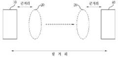
Translated fromKorean도 1은 일반적인 비독립형 전송매체를 이용한 네트워크 시스템의 구성도이다.1 is a block diagram of a network system using a general non-independent transmission medium.
도 2는 본 발명에 따른 네트워크 디바이스의 개념도이다.2 is a conceptual diagram of a network device according to the present invention.
도 3은 도 2의 네트워크 디바이스가 적용된 네트워크 시스템의 구성도이다.3 is a configuration diagram of a network system to which the network device of FIG. 2 is applied.
도 4는 도 3의 리모트 컨트롤러(20)의 네트워크 어댑터의 구성도이다.4 is a configuration diagram of a network adapter of the
도 5는 도 3의 네트워크 디바이스(40)의 네트워크 어댑터의 구성도이다.5 is a configuration diagram of a network adapter of the
도 6은 네트워크 서버에서의 네트워크 구성 방법의 순서도이다.6 is a flowchart of a network configuration method in a network server.
도 7은 리모트 컨트롤러에서의 네트워크 구성 방법의 순서도이다.7 is a flowchart illustrating a network configuration method in a remote controller.
도 8은 네트워크 디바이스에서의 네트워크 구성 방법의 순서도이다.8 is a flowchart of a network configuration method in a network device.
<도면의 주요 부분에 대한 부호의 설명><Explanation of symbols for the main parts of the drawings>
10: 네트워크 서버20: 리모트 컨트롤러10: network server 20: remote controller
22: 네트워크 어댑터40: 네트워크 디바이스22: network adapter 40: network device
본 발명은 네트워크 디바이스에 관한 것으로서, 특히 공간적인 설치 제약을 해결하면서 네트워크 연결의 신뢰성을 향상시키는 네트워크 디바이스에 관한 것이다.BACKGROUND OF THE INVENTION 1. Field of the Invention The present invention relates to network devices, and more particularly to network devices that improve the reliability of network connections while solving spatial installation constraints.
일반적인 네트워크 시스템에 있어서, 설치 공간에서의 배선 문제와, 이동성을 위해, 전력선 통신, Zigbee, RF 등과 같이 비독립형 전송매체가 사용되고 있다. 또한, 전력선 통신, Zigbee, RF 등과 같이 비독립형 전송매체를 사용하는 네트워크 시스템에서는 각 네트워크(예를 들면, 각 가정)를 구분하는 네트워크 식별자(홈코드 등)를 사용하여 네트워크를 구분하고 있다.In general network systems, non-independent transmission media such as power line communication, Zigbee, RF, etc. are used for wiring problems and mobility in an installation space. In addition, in a network system using a non-independent transmission medium such as power line communication, Zigbee, RF, and the like, networks are identified using network identifiers (such as home codes) that distinguish each network (for example, each home).
도 1은 일반적인 비독립형 전송매체를 이용한 네트워크 시스템의 구성도이다. 도 1에 도시된 바와 같이, 가정(H1)과 가정(H1)은 비독립형 전송매체인 전력선에 의해 서로 물리적으로 연결되어 있다.1 is a block diagram of a network system using a general non-independent transmission medium. As shown in FIG. 1, the home H1 and the home H1 are physically connected to each other by a power line which is a non-independent transmission medium.
가정(H1)은 네트워크 서버(1a)와, 가전 기기(2a), (2b)로 이루어진 네트워크 시스템이고, 가정(H2)은 네트워크 서버(1b)와, 가전 기기(2c)로 이루어진 네트워크 시스템이라 할 수 있다. 또한, 가정(H1)은 예를 들면, 홈코드로 0x11이 설정되어 있고, 가정(H2)은 홈코드로 0x01이 설정되어 있을 경우, 새로운 가전 기기(2d)를 가정(H2)의 네트워크 시스템에 연결하는 방법을 생각해 본다.The home H1 is a network system composed of a network server 1a, home appliances 2a and 2b, and the home H2 is a network system composed of a network server 1b and a
일반적으로 이러한 홈코드와 같은 네트워크 식별자를 설정할 때, 이 가전 기기(2d)는 홈코드를 전혀 저장하지 않은 상태이고, 전원이 인가되면 즉, 전력선에 연결되면 네트워크 서버(1b)로부터 홈코드를 수신하여 설정함으로써, 네트워크에 연결된다. 즉, 가전 기기(2d)가 가정(H2)의 네트워크에 등록되어 네트워크 서버(1b)에 의한 제어가 이루어지게 된다.Generally, when setting a network identifier such as a home code, the
이러한 네트워크 연결 방법에 있어서, 가정(H1)과 가정(H2)에서 거의 동시에 새로운 가전기기를 네트워크에 연결하고자 하는 경우, 가전 기기(2d)는 가정(H2)의 홈코드(0x01)을 수신하기 이전에, 가정(H1)의 홈코드(0x11)를 수신하는 경우, 당연히 홈코드(0x11)로 홈코드를 설정하게 된다. 이에 따라, 가전 기기(2d)는 네트워크 서버(1b)에 의한 제어를 수행하지 않고, 네트워크 서버(1a)의 제어를 수행하게 되는 보안 상의 심각한 문제를 지니고 있다.In this network connection method, when the home H1 and the home H2 want to connect the new home appliance to the network at about the same time, before the
이러한 문제는 전력선 통신에 국한되지 않고, 비독립형 전송매체를 사용하는 네트워크 시스템에 존재하는 문제이다.This problem is not limited to power line communication, but exists in a network system using a non-independent transmission medium.
또한, 비독립형 전송매체를 사용하는 경우에도, 네트워크 서버(1b)와, 네트워크 디바이스(2d) 간에 상당한 거리가 있을 경우, 사용자가 네트워크 서버(1b)와 네트워크 디바이스(2d)에 각각 네트워크 연결을 위한 입력을 해야 하므로, 상당한 거리의 이동에 의한 시간적인 간격에 따라 상술된 보안 상의 문제가 더욱 심각해질 수 있으며, 사용자가 그 입력과, 네트워크 연결의 확인을 위해 이러한 거리를 반복적으로 이동해야 하는 불편이 있다.In addition, even when a non-independent transmission medium is used, when there is a considerable distance between the network server 1b and the
이러한 문제점을 해결하기 위해, 본 발명은 사용자의 이동 거리를 감소시킴으로써 네트워크 연결을 편리하게 처리할 수 있는 네트워크 디바이스 및 그의 네트 워크 구성 방법을 제공하는 것을 목적으로 한다.In order to solve this problem, an object of the present invention is to provide a network device and a method for constructing the network thereof that can conveniently handle the network connection by reducing the user's travel distance.
또한, 본 발명은 비독립형 전송매체를 사용하는 네트워크 시스템에서의 신뢰성 높은 네트워크 연결 및 등록을 성취하는 네트워크 디바이스 및 그의 네트워크 구성 방법을 제공하는 것을 목적으로 한다.It is also an object of the present invention to provide a network device and a network configuration method thereof for achieving a reliable network connection and registration in a network system using a non-independent transmission medium.
또한, 본 발명은 사용자의 최소한의 조작에 의해 해당 네트워크에 안정적으로 연결되도록 하는 네트워크 디바이스 및 그의 네트워크 구성 방법을 제공하는 것을 목적으로 한다.In addition, an object of the present invention is to provide a network device and a method for constructing the network thereof that can be stably connected to the corresponding network by minimal manipulation of the user.
본 발명인 네트워크 디바이스는 사용자로부터 네트워크 연결 시작 요청에 대한 입력을 획득하는 입력수단과, 근거리 내의 네트워크를 검색하고, 상기 검색된 네트워크에 대한 네트워크 연결을 수행하는 네트워크 어댑터 및, 상기 네트워크 어댑터로 상기 네트워크 연결 시작 요청을 송신하여 상기 네트워크 연결이 수행되도록 하는 제어수단으로 이루어진다.The network device of the present invention comprises input means for obtaining an input for a network connection start request from a user, a network adapter for searching a network within a short distance, and performing a network connection to the searched network, and starting the network connection with the network adapter. Control means for transmitting the request to perform the network connection.
이때, 상기 네트워크 어댑터는 최소 송신 전력을 이용하여 상기 네트워크를 검색하는 것이 바람직하다.In this case, the network adapter preferably searches for the network using a minimum transmission power.
또한, 상기 네트워크 어댑터는 단수의 네트워크에 대한 네트워크 연결을 수행하는 것이 바람직하다.In addition, the network adapter preferably performs a network connection to a single network.
또한, 상기 네트워크 어댑터는 상기 네트워크 연결을 수행하여 네트워크 정보를 획득하는 것이 바람직하다.In addition, the network adapter preferably performs network connection to obtain network information.
또한, 상기 네트워크 어댑터는 상기 네트워크 정보에 따라 네트워크 서버에 대한 연결을 수행하는 것이 바람직하다.In addition, the network adapter preferably connects to a network server according to the network information.
또한, 본 발명인 네트워크 어댑터는 근거리 내의 네트워크를 검색하는 검색수단과, 상기 검색된 네트워크의 개수에 따라 네트워크 연결을 수행하는 등록수단을 구비한다.In addition, the inventors of the network adapter is provided with search means for searching a network within a short distance and registration means for performing a network connection according to the number of the searched network.
또한, 본 발명인 네트워크디바이스의 네트워크 구성 방법은 사용자로부터 네트워크 연결 시작 요청에 대한 입력을 획득하는 단계와, 상기 네트워크 연결 시작 요청에 따라 근거리 내의 네트워크를 검색하는 단계와, 상기 검색된 네트워크에 대한 네트워크 연결을 수행하는 단계를 포함한다.In addition, the network configuration method of the network device of the present invention, the step of obtaining an input for a network connection start request from a user, searching for a network within a short distance according to the network connection start request, and network connection for the searched network Performing the steps.
이하에서, 본 발명은 본 발명의 실시예 및 첨부도면에 기초하여 상세하게 설명되었다. 그러나, 이하의 실시예들 및 도면에 의해 본 발명의 범위가 제한되지는 않으며, 본 발명의 범위는 후술한 특허청구범위에 기재된 내용에 의해서만 제한될 것이다.In the following, the invention has been described in detail based on the embodiments of the invention and the accompanying drawings. However, the scope of the present invention is not limited by the following embodiments and drawings, and the scope of the present invention will be limited only by the contents described in the claims below.
도 2는 본 발명에 따른 네트워크 디바이스의 개념도이다. 도 2에 도시된 바와 같이, 네트워크 서버(10)는 특정 공간에 놓여져서 네트워크의 제어 등을 수행하며, 이미 형성된 네트워크에 연결되고자 하는 네트워크 디바이스(40)도 역시 사용자의 편의 또는 기능상의 요구에 의해 특정 공간에 놓여지게 된다. 즉, 네트워크 서버(10)(예를 들어, 주방에 설치된 냉장고)와, 네트워크 디바이스(40)(예를 들면, 세탁실에 설치된 세탁기)가 원거리에 놓여진다. 이럴 경우, 종래 기술에서와 같이, 네트워크 디바이스(40)를 연결하고자 하는 경우, 네트워크 서버(10)와, 네트워크 디바이스(40) 간을 이동하면서 네트워크 연결을 수행해야 한다.2 is a conceptual diagram of a network device according to the present invention. As shown in FIG. 2, the
이러한 거리 이동을 해결하기 위해, 본 발명에서는 네트워크 디바이스와 같이 통신 기능을 수행할 수 있는 리모트 컨트롤러(20)가 네트워크 서버(10)와 근거리에서 네트워크 서버(10)에 대한 네트워크 연결을 수행하고, 이 네트워크 연결에 의한 네트워크 정보를 저장하고, 사용자가 이 리모트 컨트롤러(20)를 들고 네트워크 디바이스(40)가 놓은 장소로 이동하여, 기저장된 네트워크 정보를 이용하여 네트워크 디바이스(40)와 근거리에서 네트워크 연결을 수행한다. 이에 따라 네트워크 디바이스(40)는 네트워크 정보를 수신하여 저장하고, 이 네트워크 정보를 이용하여 원거리에 놓은 네트워크 서버(10)와 자동적으로 네트워크 서버(10)에 대한 검색을 수행하여, 네트워크 서버(10)와의 네트워크 연결을 완료하게 된다.In order to solve such a distance movement, in the present invention, the
도 3은 도 2의 네트워크 디바이스가 적용된 네트워크 시스템의 구성도이다. 네트워크 시스템은 소정 영역 내의 디바이스를 제어 및 모니터링하는 네트워크 서버(10)와, 네트워크 서버(10)와 비독립형 전송 매체에 의해 통신을 수행하는 네트워크 디바이스의 일종인 리모트 컨트롤러(20)와, 네트워크 서버(10) 및 리모트 컨트롤러(20)와 비독립형 전송 매체에 의해 통신을 수행하는, 신규로 네트워크 연결되고자 하는 네트워크 디바이스(40)로 이루어진다.3 is a configuration diagram of a network system to which the network device of FIG. 2 is applied. The network system includes a
여기서, 네트워크 서버(10)와, 리모터 컨트롤러(20)는 네트워크 연결을 수행 함에 있어, 통신 범위가 근거리로 제한되도록 통신을 수행하고, 또한, 리모터 컨트롤러(20)와 네트워크 디바이스(40)도 역시 근거리로 제한되도록 통신을 수행한다. 특히, 리모트 컨트롤러(20)와 네트워크 디바이스(40) 간의 네트워크 연결을 수행함에 있어서는, 리모트 컨트롤러(20)가 네트워크 정보를 제공하기 까지 네트워크 서버와 같은 기능을 수행한다. 이러한 근거리 제한 통신을 통하여, 사용자가 원하는 네트워크 서버 이외의 다른 서버와 네트워크 연결을 위한 통신이 수행될 가능성을 낮추도록 한다.In this case, the
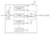
네트워크 서버(10)는 사용자로부터의 입력을 획득하는 입력수단(11)과, 비독립형 전송매체에 따른 프로토콜(예를 들면, PLC, ZigBee, RF 등)에 따른 통신을 수행하는 네트워크 어댑터(12)와, 네트워크 서버(10)가 냉장고 또는 DTV인 경우, 네트워킹 이외의 독자적인 기능을 수행하는 구동부(13)와, 사용자에게 적어도 네트워크 상태를 표시하는 표시수단(14)과, 사용자의 입력에 따라 네트워크 어댑터(12)를 제어하여, 소정의 네트워크를 구성하는 마이컴(15)으로 이루어진다.The
또한, 리모트 컨트롤러(20)의 각 구성요소인 입력수단(21)과, 네트워크 어댑터(22)와, 표시수단(23) 및 마이컴(25)은 네트워크 서버(10)의 입력수단(11)과, 네트워크 어댑터(12)와, 표시수단(14) 및 마이컴(15)에 대응되는 기본 기능을 수행한다. 보통 리모트 컨트롤러(20)의 경우, 네트워크 서버(10)와 같이 독자적인 기능을 수행하지 않으므로, 구동부를 구비하지 않는다. 다만, 도 4의 네트워크 어댑터(22)는 네트워크 보안을 위한 기능을 수행하며, 이에 대한 설명이 하기에서 개시된다. 특히, 리모트 컨트롤러(20)의 마이컴(25)은 네트워크 디바이스(40)와의 통신을 수 행할 때, 네트워크 서버(10)의 마이컴(15)과 유사하게 기능한다.In addition, the input means 21, the
또한, 네트워크 디바이스(40)는 네트워크 서버(10)의 구성요소들에 그 명칭에 대응하여 유사한 구성요소를 구비한다. 다만, 도 5의 네트워크 어댑터(42)는 도 4의 네트워크 어댑터(22)와 같이 네트워크 보안을 위한 기능을 수행한다.In addition, the
도 4은 도 3의 리모트 컨트롤러(20)의 네트워크 어댑터의 구성도이다. 도시된 바와 같이, 네트워크 어댑터(22)는 비독립형 전송매체를 통한 데이터의 송수신을 수행하는 송수신부(31)와, 리모트 컨트롤러(20)의 마이컴(25)과의 데이터 송수신을 수행하는 접속 인터페이스(32)와, 비독립형 전송매체에 따른 프로토콜에 따른 통신 제어를 수행하는 제어부(33)로 이루어지고, 네트워크 연결 결과 등을 표시하는 표시부(34)를 추가적으로 구비할 수 있다.4 is a configuration diagram of a network adapter of the
여기서, 송수신부(31)는 자세하게 도시되지는 않았으나, 복조부, 변조부, 증폭부, 안테나 등으로 구성된 것으로, 그 세부 구성은 본 발명이 속하는 기술분야에 익숙한 사람에게는 용이하게 인식된다.Here, although not shown in detail, the
접속 인터페이스(32)는 마이컴(25)과의 데이터 전송을 수행하는 접속 수단에 해당되며, 마이컴(25)로부터의 명령 및 데이터의 수신과, 제어부(33)로부터의 이러한 명령에 대한 결과 보고 및 데이터의 송신을 수행하는 것이다.The
제어부(33)는 적용된 프로토콜에 따른 통신 방식에 따라 네트워크 연결과, 이후의 데이터 송수신 등을 제어하는 소자이다. 본 발명에서는 이 제어부(33)가 신규한 네트워크 디바이스인 리모트 컨트롤러(20)를 네트워크 서버(10)가 제어하는 네트워크에 연결되도록 하는 과정에 대하여 먼저 설명한다.The
표시부(34)는 네트워크 어댑터(22)의 전원 공급 상태, 또는 동작 상태(정상 동작, 동작 오류 등)를 표시할 수도 있고, 리모트 컨트롤러(20)가 별도의 표시수단을 구비하지 못한 경우, 네트워크 연결 결과를 표시할 수 있다. 이 표시부(34)는 시각적 표시뿐만 아니라 청각적 표시도 가능하다.The
제어부(33)의 검색모듈(33a)은 송수신부(31)를 통하여 연결가능한 네트워크를 검색한다. 이때, 검색모듈(33a)은 근거리 통신이 가능한 최소 송신 전력으로 이러한 검색을 수행한다. 따라서, 사용자가 리모트 컨트롤러(20)를 네트워크 서버(10)의 근거리가 되도록 이동시켜야 한다. 이러한 근거리 통신에 의해, 리모트 컨트롤러(20)와 네트워크 서버(10)만이 네트워크 연결을 수행할 수 있도록 한다. 이러한 검색은 예를 들면, PLC 통신의 경우, 네트워크 서버(10)가 연결 요청 메시지를 생성하여 네트워크 디바이스(20)로 송신하므로, 이러한 연결 요청 메시지의 확인을 통하여 이루어진다. 또는, ZigBee 통신의 경우, 이러한 검색은 검색모듈(33a)이 송수신부(31)를 통하여 network join 과정에서 network join enable 상태인 PAN coordinator인 네트워크 서버(10)로부터 channel과 PAN ID의 수신의 형태로 이루어진다. 즉, 이 검색수단(33a)은 연결 가능한 네트워크(또는 네트워크 서버(10))에서 네트워크 식별자를 수신하여, 이에 따라 네트워크를 검색하게 된다.The
등록모듈(33b)은 검색모듈(33a)에 의해 검색된 네트워크 중에서 하나의 네트워크에 구성원으로 연결되도록 한다.The registration module 33b is connected to one of the networks searched by the
산정모듈(33c)은 검색모듈(33a)에 의해 검색된 네트워크의 개수를 산정하는 수단이다. 즉, 산정모듈(33c)은 네트워크 어댑터(22)가 연결될 수 있는 네트워크의 개수를 산정하여, 이에 대한 결과를 등록모듈(33b)에 알려준다. 여기서, 산정모듈(33c)은 검색모듈(33a)에 의해 검색된 네트워크의 네트워크 식별자의 종류에 따라 네트워크의 개수를 산정한다. 보통, 네트워크 서버(10)의 네트워크 어댑터(12)는 소정의 설정시간 동안 복수회의 네트워크 식별자를 전송할 수 있으므로, 산정모듈(33c)이 동일한 네트워크 식별자인 (PAN ID, channel)를 복수회 수신한 경우 네트워크는 1개이고, 상이한 네트워크 식별자를 수신한 경우는 복수개의 네트워크에 해당된다.The
산정모듈(33c)의 산정 결과에 따라, 등록모듈(33b)은 연결가능한 네트워크가 단수인 경우, 이 네트워크(즉, 네트워크 서버(10))가 사용자에 의해 네트워크 디바이스(20)가 접속되기를 원하는 네트워크인 것으로 판단하여, 이 네트워크 식별자를 자신의 네트워크 식별자로 저장하고, 이 네트워크 식별자를 이용하여 네트워크 서버(10)로의 네트워크 연결을 수행한다.According to the calculation result of the
또한, 네트워크 어댑터(22)는 신규의 네트워크 디바이스(40)에 대해서는 상술된 네트워크 서버(10)의 네트워크 어댑터(12)와 같이, 네트워크 식별자를 네트워크 디바이스(40)에 송신하고, 그에 따라 리모트 컨트롤러(20)와 네트워크 디바이스(40) 간에 네트워크 연결이 수행되도록 한다.In addition, the
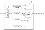
도 5는 도 3의 네트워크 디바이스(40)의 네트워크 어댑터의 구성도이다. 도 5의 네트워크 어댑터(52)는 도 4의 네트워크 어댑터(42)와 동일한 구성요소로 이루 어지나, 일부의 기능이 상이하다.5 is a configuration diagram of a network adapter of the
먼저, 네트워크 디바이스(40)가 리모트 컨트롤러(20)와 네트워크 연결을 수행할 때는 리모트 컨트롤러(20)와 네트워크 서버(10) 간의 네트워크 연결과 동일하므로, 이때의 리모트 컨트롤러(20)의 네트워크 어댑터(22)와 동일하다. 그러나, 일단, 네트워크 어댑터(42)가 리모트 컨트롤러(20)에 의해 네트워크 정보를 획득하게 되면, 등록모듈(53b)은 네트워크 정보에 따라 네트워크 서버(10)와의 네트워크 연결을 위한 메시지(예를 들면, looking for the server 메시지)를 네트워크 서버(10)로 송신하고, 이에 대한 응답으로 네트워크 서버(10)가 응답 메시지를 송신하여 등록모듈(53b)이 송수신부(51)를 통하여 수신하는 기능을 추가적으로 수행하게 된다. 즉, 네트워크 디바이스(40)의 네트워크 어댑터(42)가 리모트 컨트롤러(20)를 통하여 네트워크 정보를 획득하고 있으나, 네트워크 서버(10)는 네트워크 디바이스(40)를 식별할 수 없기 때문에 상술된 동작이 요구되는 것이다.First, since the
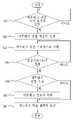
도 6은 네트워크 서버에서의 네트워크 구성 방법의 순서도이고, 도 7은 리모트 컨트롤러에서의 네트워크 구성 방법의 순서도이다. 본 실시예에서는 ZigBee 통신에 따른 구체적인 실시예를 개시한다.6 is a flowchart of a network configuration method in a network server, and FIG. 7 is a flowchart of a network configuration method in a remote controller. In this embodiment, a specific embodiment according to ZigBee communication is disclosed.
자세하게는, 도 6의 단계(S41)에서, 네트워크 서버(10)의 마이컴(15)은 입력수단(11)을 통하여 사용자로부터 네트워크 연결 시작 요청에 대응하는 입력이 이루어졌는지 판단한다. 즉, 사용자가 새로운 리모트 컨트롤러(20)를 현재의 네트워크 시스템에 연결하여 제어하고자 하는 것인지 판단한다.In detail, in step S41 of FIG. 6, the
이에 대응하여, 도 7의 단계(S51)에서, 리모트 컨트롤러(20)의 마이컴(25)도 사용자로부터의 네트워크 연결 시작 요청에 대응하는 입력이 이루어졌는지 판단한다.Correspondingly, in step S51 of FIG. 7, the microcomputer 25 of the
도 6의 단계(S42)에서, 마이컴(15)은 네트워크 어댑터(12)로 네트워크 연결 허용 명령을 송신하고, 이에 따라 네트워크 어댑터(12)는 현재 상태를 다른 네트워크 어댑터로부터의 PAN으로의 연결 허용(join enable) 상태로 전환한다.In step S42 of FIG. 6, the
도 7의 단계(S52)에서, 마이컴(25)은 네트워크 어댑터(22)로 하여금 네트워크 연결 과정(network join procedure)을 수행하도록 한다. 이에, 네트워크 어댑터(22)의 검색모듈(33a)은 네트워크 검색을 수행한다. 이때, 네트워크 어댑터(22)는 근거리 내에서의 통신만이 가능하도록 송신 전력을 최소로 하여 검색을 수행한다.In step S52 of FIG. 7, the microcomputer 25 causes the
도 6의 단계(S43)에서, 네트워크 서버(10)의 네트워크 어댑터(12)는 네트워크 어댑터(22)의 네트워크 연결 과정에 대응하여, 네트워크 연결 프로세스를 수행한다. 이는, 네트워크 어댑터(12)가 기저장하고 있는 네트워크 식별자를 소정의 시간 간격으로 외부로 송신하여, 네트워크 어댑터(22)의 검색모듈(33a)이 수신하도록 한다. 즉, 단계(S43)과 단계(S52)가 서로 유기적으로 동작하게 되며, 이러한 네트워크 연결 과정은 ZigBee 프로토콜에 규정된 바에 따라 수행된다.In step S43 of FIG. 6, the
도 6의 단계(S44)에서, 네트워크 어댑터(12)는 설정시간(t1) 동안 네트워크 연결 프로세스를 수행한다. 즉, 네트워크 어댑터(12)는 이 설정시간(t1) 동안 네트워크 연결 허용 상태를 유지하게 된다.In step S44 of FIG. 6, the
도 7의 단계(S53)에서, 네트워크 어댑터(22)는 설정시간(t2) 동안 네트워크 연결 과정을 수행한다.In step S53 of FIG. 7, the
도 7의 단계(S54)에서, 검색모듈(33a)은 검색된 네트워크 식별자를 모두 산정모듈(33c)로 보내고, 산정모듈(33c)은 수신된 네트워크 식별자의 종류에 따라 연결가능한 네트워크의 개수를 산정하여 등록모듈(33b)로 보낸다. 이에 등록모듈(33b)은 네트워크의 개수가 단수인지를 판단하며, 만약 단수이면, 단계(S55)로 진행하고, 그렇지 않으면 단계(S56)로 진행한다.In step S54 of FIG. 7, the
단계(S55)에서, 등록모듈(33b)은 수신된 네트워크 식별자에 대응하는 네트워크로 연결 요청을 멀티캐스트 방식으로 송신하고, 이에 도 6의 단계(S45)에서, 네트워크 어댑터(12)가 이를 수신하여 단계(S46)에서, 네트워크 연결 허용을 네트워크 어댑터(22)로 유니캐스트 방식으로 송신한다. 특히, 네트워크 어댑터(12)는 네트워크 어댑터(22)로부터의 연결 요청 시에 리모트 컨트롤러(20)의 MAC 주소를 등록한다. 이에 등록모듈(33b)이 네트워크 어댑터(12)로 네트워크 정보(예를 들면, 홈코드, 인증키, 암호화키 등)를 유니캐스트 방식으로 요청하고, 단계(S46)에서, 네트워크 어댑터(12)는 이에 대하여 네트워크 정보를 네트워크 어댑터(12)로 전송하며, 이에 등록모듈(33b)이 이 네트워크 정보를 저장하여, 네트워크 연결을 수행한다.In step S55, the registration module 33b transmits a connection request to the network corresponding to the received network identifier in a multicast manner, and in step S45 of FIG. 6, the
단계(S56)에서, 등록모듈(33b)은 복수의 네트워크 어디에도 연결하기를 포기하고, 수신된 네트워크 식별자를 폐기한다. 이렇게 네트워크가 복수개 검색되면, 사용자가 직접 네트워크 식별자를 입력하는 경우가 아닐 때, 등록모듈(33b)이 어떤 네트워크가 사용자가 연결을 원하는 네트워크인지 판단할 수 없기 때문에 이러한 네트워크 연결을 포기한다.In step S56, the registration module 33b gives up connecting to any of the plurality of networks and discards the received network identifier. When a plurality of networks are searched in this way, when the user does not directly input a network identifier, the registration module 33b cannot give up this network connection because it cannot determine which network the user wants to connect to.
도 6의 단계(S47)에서, 네트워크 어댑터(12)는 네트워크 정보에 대한 처리(연결 요청의 수신, 연결 허용의 송신 및 네트워크 정보의 송신 등)를 수행하였으면 리모트 컨트롤러(20)의 성공적인 네트워크 연결이 수행되었음을, 또는 네트워크 정보에 대한 처리를 수행하지 않았으면 리모트 컨트롤러(20)의 네트워크 연결이 실패하였음을 마이컴(15)에 알리고, 이에 마이컴(15)은 표시수단(14)을 통하여 이러한 네트워크 연결 결과를 알린다.In step S47 of FIG. 6, if the
도 7의 단계(S57)에서, 네트워크 어댑터(22)는 단계(S55)에 따른 경우 네트워크 연결 성공을, 또는 단계(S56)에 따른 경우 네트워크 연결 실패를 마이컴(25)에 알리고, 이에 마이컴(25)은 그 네트워크 연결 결과를 표시수단(24)을 통하여 사용자에게 알린다. 또한, 네트워크 어댑터(22)는 내장된 표시부(34)를 통하여 네트워크 연결 결과를 알릴 수도 있다. 단계(S57)에서, 리모트 컨트롤러(22)는 네트워크 연결 실패인 경우, 네트워크 연결 과정을 재수행하지 않으며, 사용자에게 표시부(34) 또는 표시수단(24)으로 그 사실을 알리고, 일정 시간이 흐른 후에 재시도하도록 사용자에게 알릴 수 있다.In step S57 of FIG. 7, the
상술된 도 6 및 7의 방법에 의해, 리모트 컨트롤러(20)의 네트워크 어댑터(22)는 네트워크 연결에 의한 네트워크 정보를 저장하며, 이후에 통신을 위해 송신전력을 정상 전력으로 재설정한다. 하기의 도 8에서, 사용자는 네트워크 정보를 저장한 리모트 컨트롤러(20)를 새롭게 네트워크에 연결하고자 하는 네트워크 디바 이스(40)의 근거리에 위치시키고, 도 6 및 도 7의 방법과 동일하게 네트워크 연결을 수행한다.By the method of FIGS. 6 and 7 described above, the
도 7은 네트워크 디바이스에서의 네트워크 구성 방법의 순서도이다. 이때, 도 5의 네트워크 서버(10)의 기능을 리모트 컨트롤러(20)가 수행하고, 네트워크 디바이스(40)가 도 6의 리모트 컨트롤러(20)의 기능을 대부분 수행하게 된다. 즉, 도 7의 단계(S61) 내지 (S66)은 도 6의 단계(S51) 내지 (S56)과 유사한 동작으로 진행된다.7 is a flowchart of a network configuration method in a network device. At this time, the
다만, 단계(S67)에서, 네트워크 디바이스(40)의 등록모듈(52b)은 수신된 네트워크 정보에 따라 네트워크 서버(10)로 연결 요청(예를 들면, looking for the sever 메시지)를 멀티캐스트 방식으로 송신하고, 이에 네트워크 어댑터(12)는 수신된 연결 요청에 포함된 네트워크 정보를 판독하여, 자신의 네트워크 정보인 경우, 등록모듈(52b)로 연결 허용을 유니캐스트 방식으로 송신하여, 네트워크 디바이스(40)와 네트워크 서버(10) 간의 연결이 이루어진다. 이때, 네트워크 어댑터(12)는 네트워크 디바이스(20)의 MAC 주소를 저장한다.However, in step S67, the registration module 52b of the
상술된 바와 같이, 사용자는 리모트 컨트롤러(20)를 네트워크 서버(10)의 근거리로 이동시키고, 각각에 네트워크 연결 시작 요청에 대응하는 입력을 수행함으로써, 리모트 컨트롤러(20)가 네트워크 서버(10)와의 네트워크 연결을 수행하고, 그 이후에, 다시 리모트 컨트롤러(20)를 네트워크 디바이스(40)의 근거리로 이동시키고, 각각에 네트워크 연결 시작 요청에 대응하는 입력을 수행함으로써, 네트워크 디바이스(40)와 리모트 컨트롤러(20) 간의 네트워크 연결이 수행된다. 또한, 네트워크 디바이스(40)는 자동적으로 네트워크 서버(10)와의 네트워크 연결을 수행하게 됨으로써, 원거리에 위치된 네트워크 디바이스(40)와 네트워크 서버(10) 간의 네트워크 연결이 완료된다.As described above, the user moves the
이러한 구성의 본 발명은 사용자의 이동 거리를 감소시킴으로써 네트워크 연결을 편리하게 처리할 수 있는 효과가 있다.The present invention of such a configuration has an effect that can conveniently handle the network connection by reducing the user's travel distance.
또한, 본 발명은 비독립형 전송매체를 사용하는 네트워크 시스템에서의 신뢰성 높은 네트워크 연결 및 등록을 성취하는 효과가 있다.In addition, the present invention has the effect of achieving a reliable network connection and registration in a network system using a non-independent transmission medium.
또한, 본 발명은 사용자의 최소한의 조작에 의해 해당 네트워크에 안정적으로 연결되도록 하는 효과가 있다.In addition, the present invention has the effect of being stably connected to the network by the minimum manipulation of the user.
Claims (14)
Translated fromKoreanPriority Applications (2)
| Application Number | Priority Date | Filing Date | Title |
|---|---|---|---|
| KR1020060066976AKR100792076B1 (en) | 2006-07-18 | 2006-07-18 | Network devices |
| US11/655,825US8090807B2 (en) | 2006-01-23 | 2007-01-22 | Home code setting method for home network system |
Applications Claiming Priority (1)
| Application Number | Priority Date | Filing Date | Title |
|---|---|---|---|
| KR1020060066976AKR100792076B1 (en) | 2006-07-18 | 2006-07-18 | Network devices |
Publications (1)
| Publication Number | Publication Date |
|---|---|
| KR100792076B1true KR100792076B1 (en) | 2008-01-04 |
Family
ID=39216876
Family Applications (1)
| Application Number | Title | Priority Date | Filing Date |
|---|---|---|---|
| KR1020060066976AExpired - Fee RelatedKR100792076B1 (en) | 2006-01-23 | 2006-07-18 | Network devices |
Country Status (1)
| Country | Link |
|---|---|
| KR (1) | KR100792076B1 (en) |
Citations (4)
| Publication number | Priority date | Publication date | Assignee | Title |
|---|---|---|---|---|
| KR100192729B1 (en) | 1994-07-29 | 1999-06-15 | 포만 제프리 엘 | Nodes and Methods for Communication in a Network |
| KR20040047630A (en)* | 2002-11-29 | 2004-06-05 | 산요덴키가부시키가이샤 | Electronic appliances network system, adapter for electronic appliances network, index server, method of connecting electronic appliances network, method of controlling adapter for electronic appliances network, and method of operating index server |
| KR20040103367A (en)* | 2003-05-30 | 2004-12-08 | 엘지전자 주식회사 | Home network system |
| KR20060045122A (en)* | 2004-04-19 | 2006-05-16 | 엘지전자 주식회사 | How to set unique code of home network and home network system for the method |
- 2006
- 2006-07-18KRKR1020060066976Apatent/KR100792076B1/ennot_activeExpired - Fee Related
Patent Citations (5)
| Publication number | Priority date | Publication date | Assignee | Title |
|---|---|---|---|---|
| KR100192729B1 (en) | 1994-07-29 | 1999-06-15 | 포만 제프리 엘 | Nodes and Methods for Communication in a Network |
| KR20040047630A (en)* | 2002-11-29 | 2004-06-05 | 산요덴키가부시키가이샤 | Electronic appliances network system, adapter for electronic appliances network, index server, method of connecting electronic appliances network, method of controlling adapter for electronic appliances network, and method of operating index server |
| KR20040103367A (en)* | 2003-05-30 | 2004-12-08 | 엘지전자 주식회사 | Home network system |
| KR20040104349A (en)* | 2003-05-30 | 2004-12-10 | 엘지전자 주식회사 | Home network system |
| KR20060045122A (en)* | 2004-04-19 | 2006-05-16 | 엘지전자 주식회사 | How to set unique code of home network and home network system for the method |
Similar Documents
| Publication | Publication Date | Title |
|---|---|---|
| US8090807B2 (en) | Home code setting method for home network system | |
| US9866892B2 (en) | IR pairing for RF4CE remote controls | |
| KR100470853B1 (en) | Network device, network connection management device, and method of installing more network device | |
| KR102002420B1 (en) | Smart home system with portable gateway | |
| EP1217475B1 (en) | Apparatus and method for remotely controlling household appliances | |
| US9294469B2 (en) | Systems and methods for establishing a connection between an appliance and a home energy management device | |
| KR100565487B1 (en) | Home appliance network system and its operation method | |
| CN104503378B (en) | A kind of robot and the method for controlling household electrical appliances based on the robot | |
| CN201749342U (en) | Control device and control system | |
| JP2002186058A (en) | Consumer electric appliance network controller and method | |
| CN105652675A (en) | Control method for intelligent household equipment, device, terminal and system | |
| CN105159121B (en) | Household appliance, startup and shutdown control method and system thereof and intelligent device | |
| CN103685733A (en) | Remote control method and terminal | |
| US8484323B2 (en) | Network system connected with multiple master devices and method for operating the same | |
| JP7281370B2 (en) | Home Appliance Systems and Home Appliances | |
| JP4377644B2 (en) | Home appliance remote control system, service providing server, and home appliance remote control method | |
| CN112305926A (en) | Distribution network control method, distribution network control device, household appliance and storage medium | |
| US10469494B2 (en) | Home network system using Z-Wave network and home automation device connection method using same | |
| JP4931659B2 (en) | Home appliance network system | |
| AU2016434810B2 (en) | Device control system | |
| KR100792076B1 (en) | Network devices | |
| KR100819588B1 (en) | Network devices | |
| CN113556723B (en) | Intelligent device activation method, intelligent device and intelligent device activation system | |
| KR20060007206A (en) | Remote control system of home appliances using mobile communication terminal | |
| KR102566786B1 (en) | Home network deivce and network connection method for home network deivce |
Legal Events
| Date | Code | Title | Description |
|---|---|---|---|
| A201 | Request for examination | ||
| PA0109 | Patent application | St.27 status event code:A-0-1-A10-A12-nap-PA0109 | |
| PA0201 | Request for examination | St.27 status event code:A-1-2-D10-D11-exm-PA0201 | |
| R17-X000 | Change to representative recorded | St.27 status event code:A-3-3-R10-R17-oth-X000 | |
| E902 | Notification of reason for refusal | ||
| PE0902 | Notice of grounds for rejection | St.27 status event code:A-1-2-D10-D21-exm-PE0902 | |
| T11-X000 | Administrative time limit extension requested | St.27 status event code:U-3-3-T10-T11-oth-X000 | |
| P11-X000 | Amendment of application requested | St.27 status event code:A-2-2-P10-P11-nap-X000 | |
| P13-X000 | Application amended | St.27 status event code:A-2-2-P10-P13-nap-X000 | |
| E701 | Decision to grant or registration of patent right | ||
| PE0701 | Decision of registration | St.27 status event code:A-1-2-D10-D22-exm-PE0701 | |
| GRNT | Written decision to grant | ||
| PR0701 | Registration of establishment | St.27 status event code:A-2-4-F10-F11-exm-PR0701 | |
| PR1002 | Payment of registration fee | St.27 status event code:A-2-2-U10-U11-oth-PR1002 Fee payment year number:1 | |
| PG1601 | Publication of registration | St.27 status event code:A-4-4-Q10-Q13-nap-PG1601 | |
| G170 | Re-publication after modification of scope of protection [patent] | ||
| PG1701 | Publication of correction | St.27 status event code:A-5-5-P10-P19-oth-PG1701 Patent document republication publication date:20080411 Republication note text:Request for Correction Notice (Document Request) Gazette number:1007920760000 Gazette reference publication date:20080104 | |
| PN2301 | Change of applicant | St.27 status event code:A-5-5-R10-R13-asn-PN2301 St.27 status event code:A-5-5-R10-R11-asn-PN2301 | |
| R18-X000 | Changes to party contact information recorded | St.27 status event code:A-5-5-R10-R18-oth-X000 | |
| R18-X000 | Changes to party contact information recorded | St.27 status event code:A-5-5-R10-R18-oth-X000 | |
| PR1001 | Payment of annual fee | St.27 status event code:A-4-4-U10-U11-oth-PR1001 Fee payment year number:4 | |
| PR1001 | Payment of annual fee | St.27 status event code:A-4-4-U10-U11-oth-PR1001 Fee payment year number:5 | |
| FPAY | Annual fee payment | Payment date:20121128 Year of fee payment:6 | |
| PR1001 | Payment of annual fee | St.27 status event code:A-4-4-U10-U11-oth-PR1001 Fee payment year number:6 | |
| FPAY | Annual fee payment | Payment date:20131122 Year of fee payment:7 | |
| PR1001 | Payment of annual fee | St.27 status event code:A-4-4-U10-U11-oth-PR1001 Fee payment year number:7 | |
| LAPS | Lapse due to unpaid annual fee | ||
| PC1903 | Unpaid annual fee | St.27 status event code:A-4-4-U10-U13-oth-PC1903 Not in force date:20141229 Payment event data comment text:Termination Category : DEFAULT_OF_REGISTRATION_FEE | |
| PN2301 | Change of applicant | St.27 status event code:A-5-5-R10-R13-asn-PN2301 St.27 status event code:A-5-5-R10-R11-asn-PN2301 | |
| PC1903 | Unpaid annual fee | St.27 status event code:N-4-6-H10-H13-oth-PC1903 Ip right cessation event data comment text:Termination Category : DEFAULT_OF_REGISTRATION_FEE Not in force date:20141229 | |
| P22-X000 | Classification modified | St.27 status event code:A-4-4-P10-P22-nap-X000 | |
| P22-X000 | Classification modified | St.27 status event code:A-4-4-P10-P22-nap-X000 | |
| PN2301 | Change of applicant | St.27 status event code:A-5-5-R10-R13-asn-PN2301 St.27 status event code:A-5-5-R10-R11-asn-PN2301 |