KR100789636B1 - Position sensing device of stack roller and stack guide and method - Google Patents
Position sensing device of stack roller and stack guide and methodDownload PDFInfo
- Publication number
- KR100789636B1 KR100789636B1KR1020060056560AKR20060056560AKR100789636B1KR 100789636 B1KR100789636 B1KR 100789636B1KR 1020060056560 AKR1020060056560 AKR 1020060056560AKR 20060056560 AKR20060056560 AKR 20060056560AKR 100789636 B1KR100789636 B1KR 100789636B1
- Authority
- KR
- South Korea
- Prior art keywords
- stack
- roller
- guide
- withdrawal
- stack guide
- Prior art date
- Legal status (The legal status is an assumption and is not a legal conclusion. Google has not performed a legal analysis and makes no representation as to the accuracy of the status listed.)
- Expired - Fee Related
Links
Images


Classifications
- G—PHYSICS
- G07—CHECKING-DEVICES
- G07F—COIN-FREED OR LIKE APPARATUS
- G07F19/00—Complete banking systems; Coded card-freed arrangements adapted for dispensing or receiving monies or the like and posting such transactions to existing accounts, e.g. automatic teller machines
- G07F19/20—Automatic teller machines [ATMs]
- G07F19/201—Accessories of ATMs
- B—PERFORMING OPERATIONS; TRANSPORTING
- B65—CONVEYING; PACKING; STORING; HANDLING THIN OR FILAMENTARY MATERIAL
- B65H—HANDLING THIN OR FILAMENTARY MATERIAL, e.g. SHEETS, WEBS, CABLES
- B65H3/00—Separating articles from piles
- B65H3/02—Separating articles from piles using friction forces between articles and separator
- B65H3/06—Rollers or like rotary separators
- B—PERFORMING OPERATIONS; TRANSPORTING
- B65—CONVEYING; PACKING; STORING; HANDLING THIN OR FILAMENTARY MATERIAL
- B65H—HANDLING THIN OR FILAMENTARY MATERIAL, e.g. SHEETS, WEBS, CABLES
- B65H29/00—Delivering or advancing articles from machines; Advancing articles to or into piles
- B65H29/52—Stationary guides or smoothers
- B—PERFORMING OPERATIONS; TRANSPORTING
- B65—CONVEYING; PACKING; STORING; HANDLING THIN OR FILAMENTARY MATERIAL
- B65H—HANDLING THIN OR FILAMENTARY MATERIAL, e.g. SHEETS, WEBS, CABLES
- B65H83/00—Combinations of piling and depiling operations, e.g. performed simultaneously, of interest apart from the single operation of piling or depiling as such
- B65H83/02—Combinations of piling and depiling operations, e.g. performed simultaneously, of interest apart from the single operation of piling or depiling as such performed on the same pile or stack
- B65H83/025—Combinations of piling and depiling operations, e.g. performed simultaneously, of interest apart from the single operation of piling or depiling as such performed on the same pile or stack onto and from the same side of the pile or stack
- B—PERFORMING OPERATIONS; TRANSPORTING
- B65—CONVEYING; PACKING; STORING; HANDLING THIN OR FILAMENTARY MATERIAL
- B65H—HANDLING THIN OR FILAMENTARY MATERIAL, e.g. SHEETS, WEBS, CABLES
- B65H2404/00—Parts for transporting or guiding the handled material
- B65H2404/10—Rollers
- B65H2404/11—Details of cross-section or profile
- B65H2404/111—Details of cross-section or profile shape
- B65H2404/1114—Paddle wheel
- B—PERFORMING OPERATIONS; TRANSPORTING
- B65—CONVEYING; PACKING; STORING; HANDLING THIN OR FILAMENTARY MATERIAL
- B65H—HANDLING THIN OR FILAMENTARY MATERIAL, e.g. SHEETS, WEBS, CABLES
- B65H2511/00—Dimensions; Position; Numbers; Identification; Occurrences
- B65H2511/20—Location in space
- B—PERFORMING OPERATIONS; TRANSPORTING
- B65—CONVEYING; PACKING; STORING; HANDLING THIN OR FILAMENTARY MATERIAL
- B65H—HANDLING THIN OR FILAMENTARY MATERIAL, e.g. SHEETS, WEBS, CABLES
- B65H2511/00—Dimensions; Position; Numbers; Identification; Occurrences
- B65H2511/40—Identification
- B65H2511/414—Identification of mode of operation
- B—PERFORMING OPERATIONS; TRANSPORTING
- B65—CONVEYING; PACKING; STORING; HANDLING THIN OR FILAMENTARY MATERIAL
- B65H—HANDLING THIN OR FILAMENTARY MATERIAL, e.g. SHEETS, WEBS, CABLES
- B65H2701/00—Handled material; Storage means
- B65H2701/10—Handled articles or webs
- B65H2701/19—Specific article or web
- B65H2701/1912—Banknotes, bills and cheques or the like
Landscapes
- Engineering & Computer Science (AREA)
- Mechanical Engineering (AREA)
- Business, Economics & Management (AREA)
- Accounting & Taxation (AREA)
- Finance (AREA)
- Physics & Mathematics (AREA)
- General Physics & Mathematics (AREA)
- Pile Receivers (AREA)
- Sheets, Magazines, And Separation Thereof (AREA)
Abstract
Translated fromKoreanDescription
Translated fromKorean도 1은 본 발명의 일실시예에 따른 스택가이드 및 스택롤러의 위치감지장치가 구비된 리사이클박스의 사시도,1 is a perspective view of a recycling box having a stack guide and a position detection device of a stack roller according to an embodiment of the present invention;
도 2a는 본 발명의 일실시예에 따른 스택가이드 및 스택롤러가 회피되는 리사이클박스의 입금동작을 설명하기 위한 개략적인 상태도,Figure 2a is a schematic state diagram for explaining the deposit operation of the recycle box that the stack guide and the stack roller is avoided according to an embodiment of the present invention,
도 2b는 본 발명의 일실시예에 따른 스택가이드 및 스택롤러가 회피되는 리사이클박스의 출금동작을 설명하기 위한 개략적인 상태도,Figure 2b is a schematic state diagram for explaining the withdrawal operation of the recycle box in which the stack guide and the stack roller is avoided according to an embodiment of the present invention,
도 3은 도 1의 리사이클박스에서 하우징을 제거한 상태의 사시도,3 is a perspective view of a state in which a housing is removed from a recycling box of FIG. 1;
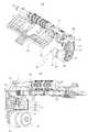
도 4는 도 3의 리사이클박스에서 입출금부의 구성부품을 나타낸 사시도,4 is a perspective view showing the components of the deposit and withdrawal unit in the recycle box of FIG.
도 5는 본 발명의 일실시예에 따른 스택가이드 및 스택롤러의 위치감지장치가 구비된 리사이클박스에서 스택가이드와 스택롤러를 회피시키는 구성부품을 나타낸 사시도,5 is a perspective view showing a component to avoid the stack guide and the stack roller in the recycle box provided with a stack guide and the position detection device of the stack roller according to an embodiment of the present invention,
도 6(a),(b)는 본 발명의 일실시예에 따른 스택가이드 및 스택롤러의 위치감지장치를 나타내는 사시도,Figure 6 (a), (b) is a perspective view showing a position detection device of the stack guide and the stack roller according to an embodiment of the present invention,
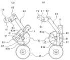
도 7(a),(b)는 본 발명의 일실시예에 따른 스택가이드 및 스택롤러의 위치감 지장치가 구비된 리사이클박스의 동작을 설명하기 위한 동작상태도.Figure 7 (a), (b) is an operating state diagram for explaining the operation of the recycling box equipped with a stack guide and the position detection device of the stack roller according to an embodiment of the present invention.
*도면의 주요부분에 대한 부호의 설명** Description of the symbols for the main parts of the drawings *
10 : 스택롤러10a : 날개편10:
11 : 스택롤러선회축20 : 스택가이드11: stack roller pivot 20: stack guide
21 : 스택가이드걸림편30 : 회동기어21: Stack Guide Jam 30: Rotating Gear
31 : 가이드돌기40 : 구동모터31: guide protrusion 40: drive motor
41 : 구동기어50 : 슬라이드바41: drive gear 50: slide bar
51 : 슬라이드장공60 : 링크연결부51: slide slot 60: link connection
61 : 제1링크바62 : 제2링크바61: first link bar 62: second link bar
63 : 제3링크바64 : 제1링크바선회축63: third link bar 64: first link bar pivot
70 : 가로봉80 : 위치감지부70: horizontal bar 80: position detection unit
81 : 결합축82 : 감지판81: coupling shaft 82: sensing plate
83a : 출금위치감지센서83b : 입금위치감지센서83a:
84 : 센서지지브라켓110 : 푸쉬플레이트84: sensor support bracket 110: push plate
310 : 픽업롤러320 : 피드롤러310: pickup roller 320: feed roller
321 : 피드롤러회전축330 : 가이드롤러321: feed roller rotation axis 330: guide roller
331 : 가이드롤러브라켓331: Guide Roller Bracket
본 발명은 스택롤러 및 스택가이드의 위치감지장치 및 그 방법에 관한 것으로, 보다 상세하게는 입출금이 모두 구현되는 리사이클박스에서 지폐류 이송경로상으로 진입되어 지폐류 입금동작을 수행하는 스택가이드 및 스택롤러의 위치를 감지할 수 있는 위치감지장치 및 그 방법에 관한 것이다.The present invention relates to a stack roller and a position detection device of the stack guide and a method thereof, and more particularly, a stack guide and a stack to enter the bill transfer path in the recycling box in which all the deposit and withdrawal is implemented to perform a bill transfer operation The present invention relates to a position sensing device capable of sensing the position of a roller and a method thereof.
리사이클박스(recyclebox)란 금융자동화기기 내에 장착되어 출금될 지폐류를 보관하고 있거나 입금되는 지폐류를 적재하는 환류식 보관함을 일컫는 것으로, 금융자동화기기 중에서도 입출금이 모두 구현되는 지폐류자동입출금기 내에 설치되는 것이다.A recycling box is a reflux type storage box for storing banknotes to be withdrawn or loaded into the automatic teller machine, and is installed in the automatic teller machine where all the deposits and deposits are implemented. will be.
일례로 리사이클박스는 상면에 지폐류가 적재되어 승하강되는 푸쉬플레이트, 상기 푸쉬플레이트 상측으로 설치되어 상기 푸쉬플레이트 상면에 적재되어 있던 지폐류를 출금하는 복수개의 출금롤러와 입금되는 지폐류를 상기 리사이클박스 상면으로 투입적재하는 복수개의 입금롤러를 포함하여 이루어진다.For example, a recycling box includes a push plate on which a banknote is loaded and lowered on an upper surface thereof, a plurality of withdrawal rollers which are installed on the push plate and withdraw the banknotes loaded on an upper surface of the push plate, and the banknotes that are deposited. It comprises a plurality of deposit rollers to be loaded into the box upper surface.
또한, 상기 리사이클박스는 입금동작 수행시에는 입금되는 지폐류가 출금롤러와 접촉되지 않도록 하는 한편 입금되는 지폐류의 이송경로를 가이드하도록 하향선회되는 스택가이드, 지폐류 이송경로상에 날개편이 진입하여 상기 스택가이드를 따라 투입되는 지폐류의 후단을 타격하여 투입되는 지폐의 정렬 및 스택보조하는 스택롤러 등을 더 포함하여 안정적인 입금동작이 수행되도록 이루어진다.In addition, the recycling box is a stack guide that is turned downward to guide the transport path of the bills to be deposited while the bills are not in contact with the withdrawal roller during the deposit operation, the wing piece enters the transport path It further comprises a stacking roller for aligning and stack-assisted banknotes hit by hitting the rear end of the banknotes introduced along the stack guide is made to perform a stable deposit operation.
구체적으로, 상기 리사이클박스는 지폐류입금동작 수행시 상기 푸쉬플레이트가 하강하여 지폐류 입금을 위한 공간이 확보되면 입금되는 지폐류가 입금롤러에 의해 확보된 공간으로 투입되어 상기 푸쉬플레이트 상면에 적재되는 한편 상기 스 택가이드 및 스택롤러에 의해 투입적재가 보조되도록 하고, 지폐류출금동작 수행시 상기 푸쉬플레이트가 상승하여 그 상면의 지폐류가 출금롤러의 저단에 가압되도록 함으로써 적재되어 있던 지폐류가 낱장분리 및 출금되도록 하는 구조이다.Specifically, the recycle box is when the push plate is lowered during the banknotes deposit operation to secure space for banknotes deposit is put into the space secured by the deposit roller is loaded on the upper surface of the push plate On the other hand, the loading guide is assisted by the stack guide and the stack roller, and when the banknote withdrawal operation is performed, the push plate is raised so that the banknotes on the upper surface thereof are pressed to the lower end of the withdrawal roller. It is a structure to separate and withdraw money.
한편, 상기 스택가이드는 출금동작 수행시에는 상측으로 상향선회됨으로써 상기 푸쉬플레이트가 상기 출금롤러와 가압접촉되어야 하고, 이에 상기 출금롤러의 저단에 상기 푸쉬플레이트 상면의 지폐류가 접촉하여 지폐류 분리 및 출금동작이 수행되어야 한다.On the other hand, the stack guide is turned upwards when the withdrawal operation is performed, the push plate should be in pressure contact with the withdrawal roller, the banknotes of the upper surface of the push plate is in contact with the lower end of the withdrawal roller to separate the bills and Withdrawal operation must be performed.
또한 상기 스택롤러도 출금동작 수행시에는 하측으로 하향선회되어 지폐류 이송경로상에서 회피되어야 하고, 그로 인해 출금동작이 안정적으로 이루어지게 된다.In addition, the stack roller is also turned downward when the withdrawal operation is to be avoided on the banknote conveyance path, thereby making the withdrawal operation stable.
이 경우 상기 스택가이드와 스택롤러의 상향선회 또는 하향선회되는 상태를 감지하여 입금동작과 출금동작이 원활히 이루어질 수 있도록 제어할 수 있는 장치가 필요하게 된다.In this case, there is a need for an apparatus capable of controlling the deposit and withdrawal operations to be smoothly detected by detecting a state in which the stack guide and the stack roller are turned upward or downward.
따라서 본 발명은 상술한 제반 문제점을 해결하기 위해 안출된 것으로, 리사이클박스에서 스택가이드 및 스택롤러의 위치를 감지함으로써 리사이클박스에서 안정적인 입금 및 출금동작이 수행되도록 할 수 있는 스택롤러 및 스택가이드의 위치감지장치 및 그 방법을 제공하고자 함에 그 목적이 있다.Therefore, the present invention has been made to solve the above-mentioned problems, the position of the stack roller and the stack guide that can perform a stable deposit and withdrawal operation in the recycle box by detecting the position of the stack guide and the stack roller in the recycle box It is an object of the present invention to provide a sensing device and a method thereof.
상기한 목적을 달성하기 위한 본 발명의 스택가이드 및 스택롤러의 위치감지 장치는, 입금되는 지폐류를 투입하는 피드롤러의 하측 외연부에 접촉하되, 복수개의 날개편이 지폐류의 후단을 타격하여 입금되는 지폐류를 스택정렬하며, 출금시에는 날개편이 지폐류 이송경로상에서 회피되도록 설치되는 스택롤러; 상기 피드롤러의 회전축에 결합되어 입금시에는 하향선회되고 출금시에는 상향선회되는 스택가이드; 상기 스택롤러와 스택가이드의 입금시와 출금시의 각 위치를 감지하기 위한 위치감지부; 를 포함하여 이루어진 것을 특징으로 한다.The stack guide and the position detection device of the stack roller of the present invention for achieving the above object is in contact with the lower outer edge of the feed roller for feeding the bills to be deposited, a plurality of blade pieces hit the rear end of the bills to deposit Stacked sorting of the bills to be, and withdrawal, the stacking roller is installed so that the wing piece is avoided on the bills conveying path; A stack guide which is coupled to the rotary shaft of the feed roller and pivots downward when depositing and upward when depositing; A position sensing unit for sensing respective positions of the stack roller and the stack guide when depositing and withdrawing money; Characterized in that comprises a.
이 경우 상기 위치감지부는, 감지판을 감지하여 스택가이드와 스택롤러의 출금시의 위치를 감지하는 출금위치감지센서와 입금시의 위치를 감지하는 입금위치감지센서로 이루어진 것을 특징으로 한다.In this case, the position detecting unit is characterized by consisting of a position detection sensor for detecting the position at the time of deposit and the withdrawal position sensor for detecting the position of the stack guide and the stack roller withdrawal by detecting the sensing plate.
여기서 상기 스택롤러가 편심되어 설치되는 스택롤러선회축, 상기 스택가이드의 후방에 횡설되어 상기 스택가이드와 조립설치되는 가로봉, 일면에는 가이드돌기가 형성되고 구동모터로부터 회전구동력을 전달받아 회전되는 회동기어, 일단은 상기 스택롤러선회축과 결합되고 타단에는 길이방향으로 형성된 슬라이드장공에 상기 가이드돌기가 삽입되어 상기 회동기어의 회전에 따라 슬라이딩 선회되어 상기 가로봉을 선회시키는 슬라이드바를 더 포함하여 이루어지고; 상기 감지판은 상기 구동모터의 회전에 연동되도록 설치되는 것이 바람직하다.Here, the stack roller pivot shaft which the stack roller is eccentrically installed, the horizontal rod which is rolled up to the rear of the stack guide to be assembled with the stack guide, and a guide protrusion is formed on one surface and is rotated by receiving a rotation driving force from the driving motor. And a slide bar coupled to the stack roller pivot shaft at one end thereof and inserted into the slide hole formed in the longitudinal direction at the other end thereof, the slide bar being pivotally slid according to the rotation of the pivoting gear to pivot the horizontal rod; The sensing plate is preferably installed to be linked to the rotation of the drive motor.
또한 상기 위치감지부에는, 일측끝단이 회동기어의 결합홈에 연결된 결합축이 구비되고, 상기 결합축의 타측끝단에 감지판이 연결되며, 상기 결합축의 양단은 디컷형상으로 이루어질 수 있다.In addition, the position sensing unit, one end is provided with a coupling shaft connected to the coupling groove of the rotary gear, the sensing plate is connected to the other end of the coupling shaft, both ends of the coupling shaft may be made in a de-cut shape.
한편, 본 발명의 스택롤러 및 스택가이드의 위치감지방법은, 고객으로부터 입력된 지폐입금신호가 제어부에 수신되는 단계; 상기 신호를 수신받은 제어부로부터 스택가이드와 스택롤러를 구동시키는 구동모터에 구동신호가 송신되는 단계; 상기 구동모터에 의해 스택가이드 및 스택롤러의 위치가 입금위치에 있게 되면 입금위치감지센서로부터 스택가이드 및 스택롤러가 입금위치에 있다는 신호가 제어부에 송신되는 단계; 상기 제어부에서 스택가이드와 스택롤러의 입금위치신호가 수신되면 리사이클박스 내부로 지폐가 입금되도록 기기를 제어하는 단계;로 이루어진 것을 특징으로 한다.On the other hand, the position detection method of the stack roller and the stack guide of the present invention, the banknote received signal input from the customer receiving the step; Transmitting a driving signal to a driving motor for driving the stack guide and the stack roller from the control unit receiving the signal; When the position of the stack guide and the stack roller is in the deposit position by the driving motor, transmitting a signal from the deposit position detecting sensor to the control unit indicating that the stack guide and the stack roller are in the deposit position; When the control unit receives the deposit position signal of the stack guide and the stack roller in the control unit, controlling the device to deposit the bill into the recycle box; characterized in that consisting of.
또한, 본 발명의 다른 스택롤러 및 스택가이드의 위치감지방법은, 고객으로부터 입력된 지폐출금신호가 제어부에 수신되는 단계; 상기 신호를 수신받은 제어부로부터 스택가이드와 스택롤러를 구동시키는 구동모터에 구동신호가 송신되는 단계; 상기 구동모터에 의해 스택가이드 및 스택롤러의 위치가 출금위치에 있게 되면 출금위치감지센서로부터 스택가이드 및 스택롤러가 출금위치에 있다는 신호가 제어부에 송신되는 단계; 상기 제어부에서 스택가이드와 스택롤러의 출금위치신호가 수신되면 리사이클박스 내부의 지폐가 출금되도록 기기를 제어하는 단계;로 이루어진 것을 특징으로 한다.In addition, the position detection method of another stack roller and the stack guide of the present invention, the step of receiving a banknote withdrawal signal input from the customer to the control unit; Transmitting a driving signal to a driving motor for driving the stack guide and the stack roller from the control unit receiving the signal; When the position of the stack guide and the stack roller is in the withdrawal position by the driving motor, transmitting a signal from the withdrawal position sensor to the controller to indicate that the stack guide and the stack roller are at the withdrawal position; And controlling the device to withdraw the banknotes inside the recycle box when the stack guide and the stack roller withdrawal signals are received by the control unit.
이하 본 발명의 바람직한 일실시예에 의한 구성 및 작용효과를 예시도면을 참조하여 상세히 설명한다.Hereinafter, the configuration and the effect according to the preferred embodiment of the present invention will be described in detail with reference to the accompanying drawings.
도 1은 본 발명의 일실시예에 따른 스택가이드 및 스택롤러의 위치감지장치가 구비된 리사이클박스의 사시도이고, 도 2a는 본 발명의 일실시예에 따른 스택가이드 및 스택롤러가 회피되는 리사이클박스의 입금동작을 설명하기 위한 개략적인 상태도이며, 도 2b는 본 발명의 일실시예에 따른 스택가이드 및 스택롤러가 회피되는 리사이클박스의 출금동작을 설명하기 위한 개략적인 상태도이다.1 is a perspective view of a recycling box having a stack guide and a position detection device of a stack roller according to an embodiment of the present invention, Figure 2a is a recycle box in which the stack guide and the stack roller is avoided according to an embodiment of the present invention Figure 2b is a schematic state diagram for explaining the operation of the deposit, Figure 2b is a schematic state diagram for explaining the withdrawal operation of the recycling box avoiding the stack guide and the stack roller according to an embodiment of the present invention.
본 발명의 일실시예에 따른 스택가이드 및 스택롤러의 위치감지장치가 구비된 리사이클박스는, 일례로 상면에 지폐류가 적층되어 승강되는 푸쉬플레이트(110)가 내부에 설치되는 스택본체부(100), 상기 스택본체부(100)의 상측으로 설치되고 상면에는 출금될 지폐류가 인출되는 출금구(301)와 입금되는 지폐류가 인입되는 입금구(302)와 푸쉬플레이트(110) 상면의 지폐류를 낱장분리하는 픽업롤러(310)와 상기 픽업롤러(310)에서 낱장분리된 지폐류를 출금이송하거나 입금구(302)를 통하여 인입되는 지폐류를 푸쉬플레이트(110) 상면으로 투입하는 피드롤러(320)와 상기 피드롤러(320)의 하측에 설치되는 가이드롤러브라켓(331)에 회전지지되고 그 외연부가 피드롤러(320)의 하측 외연부에 접촉되는 가이드롤러(330)로 이루어지는 입출금부(300)가 구비되는 한편, 상기 스택본체부(100)와 상기 입출금부(300)는 도어(210)에 의해 개폐되는 리사이클박스의 하우징(200) 내에 조립 설치된다.The recycling box provided with the stack guide and the position detection device of the stack roller according to an embodiment of the present invention, for example, the
상기 입출금부(300)는 도 2a 및 도 2b에 도시된 바와같이 입출금동작시 지폐류의 원활한 입금 및 출금이송을 보조하기 위한 반송롤러(360), 반송롤러(360)의 출금구(301)측에는 반송롤러(360)의 외연부와 접촉하여 출금지폐류를 반송롤러(360)측으로 가압하는 출금부핀치롤러(361), 반송롤러(360)의 입금구(302)측에는 반송롤러(360)의 외연부와 접촉하여 입금지폐류를 반송롤러(360)측으로 가압하는 입금부핀치롤러(362)가 추가로 설치되는 것이 바람직하다.As shown in FIGS. 2A and 2B, the deposit and
이와같은 구성에 의해 상기 리사이클박스는 피드롤러(320)와 반송롤러(360) 의 정역방향회전에 의해 입금 또는 출금이 모두 구현된다.By such a configuration, the recycling box is implemented to deposit or withdraw by both the forward and reverse rotation of the
이러한 리사이클박스의 입금동작을 도 2a를 참조하여 살펴보면, 금융자동화기기의 메인반송로(도면에 표현되지 않음)따라 상기 리사이클박스의 입금구(302)를 통하여 인입되는 지폐류는 반송롤러(360)의 반시계방향 회전에 의해 상기 리사이클박스 내부로 인입되어 시계방향 회전되는 피드롤러(320)와 그 하측의 피드롤러(320)의 외연부와 접촉하여 함께 회전되는 가이드롤러(330)의 사이로 통과되어 푸쉬플레이트(110)의 상면으로 투입적재된다.Referring to the deposit operation of the recycling box with reference to Figure 2a, according to the main transport path (not shown in the figure) of the automated teller machine bills introduced through the
이때, 푸쉬플레이트(110)는 하측으로 하강하여 상기 리사이클박스 내에 입금공간이 확보되어야 하고, 스택가이드(20)는 하향선회되어 지폐류 이송경로상으로 진입하여 입금되는 지폐류를 입금가이드하여야 하며, 스택롤러(10)는 날개편(10a)이 투입되는 지폐류의 후단을 타격하여 지폐류를 정렬 및 스택보조하도록 지폐류 이송경로상으로 진입하여야 한다.At this time, the
또한, 스택가이드(20)는 하향선회되어 있으므로 픽업롤러(310)가 지폐류 이송경로를 따라 입금되는 지폐류와 간섭되는 것을 방지한다.In addition, since the
이러한 리사이클박스의 출금동작을 도 2b를 참조하여 살펴보면, 상기 푸쉬플레이트(110) 상면의 지폐류는 픽업롤러(310)의 저단에 가압접촉되어 픽업롤러(310)의 주기적인 반시계방향 회전에 의해 낱장분리되며 역시 반시계방향회전하는 피드롤러(320)와 그 하측의 가이드롤러(330) 사이로 통과되어 반시계방향회전되는 반송롤러(360)를 지나 출금구(301)를 통하여 금융자동화기기의 메인반송로(도면에 표현되지 않음)로 인출된다.Referring to the withdrawal operation of the recycling box with reference to Figure 2b, the bills on the upper surface of the
이때 스택가이드(20)는 상향선회되어 픽업롤러(310)의 노출된 저단에 푸쉬플레이트(110)가 상승하여 가압접촉되어야 하고, 스택롤러(10)는 날개편(10a)이 지폐류 이송경로상에서 회피되어야 한다.At this time, the
도 3은 도 1의 리사이클박스에서 하우징을 제거한 상태의 사시도, 도 4는 도 3의 리사이클박스에서 입출금부의 구성부품을 나타낸 사시도, 도 5는 본 발명의 일실시예에 따른 스택가이드 및 스택롤러의 위치감지장치가 구비된 리사이클박스에서 스택가이드와 스택롤러를 회피시키는 구성부품을 나타낸 사시도, 도 6(a),(b)는 본 발명의 일실시예에 따른 스택가이드 및 스택롤러의 위치감지장치를 나타내는 사시도이다.3 is a perspective view of a state in which the housing is removed from the recycling box of FIG. 1, FIG. 4 is a perspective view showing components of an input / output unit in the recycling box of FIG. 3, and FIG. 5 is a stack guide and a stack roller according to an embodiment of the present invention. 6A and 6B are perspective views illustrating components for avoiding the stack guide and the stack roller in a recycling box having a position sensing device. FIGS. 6 (a) and 6 (b) illustrate the position guide of the stack guide and the stack roller according to an embodiment of the present invention. It is a perspective view showing.
이에 본 발명의 일실시예에서는 리사이클박스의 입금동작을 보조하는 스택가이드(20) 및 스택롤러(10)가 입금동작시에는 지폐류 이송경로상에 진입하여 있지만, 출금동작시에는 지폐류 이송경로상에서 회피되어 안정적인 출금동작이 구현되도록 한다.Therefore, in one embodiment of the present invention, the
상기한 도 2a 및 도 2b를 함께 참조하여 살펴보면, 스택롤러(10)는 가이드롤러브라켓(331)을 관통하여 설치되는 스택롤러선회축(11)에 편심되어 설치되는 한편, 그 외연부가 피드롤러(320)의 하측 외연부에 접촉되어 피드롤러(320)의 입금회전시 함께 회전되는 것이다.2A and 2B, the
스택가이드(20)는 피드롤러회전축(321)에 결합되되, 그 후방에 횡설되어 조립설치되는 가로봉(70)의 선회에 의해 입금시에는 하향선회되고 출금시에는 상향선회된다.The
일례로, 스택가이드(20)는 그 후면에 'ㄴ' 자 형상으로 절곡형성된 스택가이드걸림편(21)이 형성되고, 상기 스택가이드걸림편(21)에는 가로봉(70)이 횡설되어 가로봉(21)의 선회에 따라 스택가이드(20)가 함께 선회되는 것이며, 가로봉(70)은 입출금부(300)의 일측에 형성되는 가로봉지지브라켓(69)에 회전지지되는 후술할 제1링크바선회축(64)의 회전에 의해 선회되는 것이다.For example, the
한편, 일면에는 가이드돌기(31)가 형성되고 구동모터(40)로부터 회전구동력을 전달받아 정역방향 회전되는 회동기어(30)가 일례로 스택본체부(100)의 일면에 설치된다.On the other hand, the
구동모터(40)는 도시되지 않았지만 스택본체부(100)의 배면에 설치되는 것이 바람직하되 회동기어(30)를 정역방향 회전시키는데에만 사용되는 것이 더욱 바람직며, 일례로 회동기어(30)에 직접연결설치되는 것은 물론이고 도시된 바와같이 구동기어(41)를 중계시켜 설치함으로써 구동기어(41)와 회동기어(30)의 기어비를 달리하여 감속을 구현하는 것도 가능하다.Although not shown, the driving
또한, 일단은 스택롤러선회축(11)과 결합되고 타단은 길이방향으로 형성된 슬라이드장공(51)이 형성되어 상기 회동기어(30)의 가이드돌기(31)에 삽입되어 회동기어(30)의 회전에 따라 슬라이딩 선회되는 슬라이드바(50)가 구비된다. 한편, 도 5에 도시된 바와같이 슬라이드바(50)의 일단에는 결합돌기(52)가 돌출형성되어있는데 상기 결합돌기(52)에는 도 4에 도시된 바와같이 일단이 'D'커팅된 스택롤러선회축(11)이 끼워지는 요홈(도면에 표현되지 않음)이 형성된다.In addition, one end is coupled to the
또한, 스택가이드(20)의 후방에는 상술한 바와같이 가로봉(70)이 횡설되어 스택가이드(20)와 조립설치된다.In addition, the
이에 회동기어(30)의 정역방향회전에 따라 스택롤러(10)와 스택가이드(20)가 지폐류 이송경로상으로 진입되거나 회피되도록 슬라이드바(50)와 가로봉(70)의 사이에는 복수개의 링크바(61, 62, 63) 등이 구비된 링크연결부(60)가 설치된다.Accordingly, a plurality of links are provided between the
링크연결부(60)는 가로봉(70)이 일단에 결합되는 제1링크바(61), 제1링크바의 타단에 결합되고 정역방향회전하여 제1링크바(61)를 선회시키는 제1링크바선회축(64), 제1링크바선회축(64)이 일단에 결합되는 제2링크바(62), 일단은 제2링크바(62)의 타단과 힌지결합되고 타단은 슬라이드바(50)의 일측에 힌지결합되는 제3링크바(63)를 포함하여 이루어진다.The
상기 회동기어(30)와 인접한 위치에는, 상기 스택롤러(10)와 스택가이드(20)의 위치를 입금시와 출금시 각각 감지할 수 있도록 위치감지부(80)가 설치된다. 상기 위치감지부(80)는 구동모터(40)의 회전에 연동되는 감지판(82), 상기 감지판(82)의 위치를 감지함으로써 입금시와 출금시 스택롤러(10)와 스택가이드(20)의 위치를 감지하는 출금위치감지센서(83a)와 입금위치감지센서(83b)이 구비된다.In the position adjacent to the
이 경우 상기 감지판(82)은 결합축(81)에 의해 회동기어(30)와 연결되어 구동모터(40)의 회전에 연동되게 된다. 이를 위해 상기 회동기어(30)에는 결합홈(32)이 형성되고, 상기 결합축(81)은 일단이 결합홈(32)에 타단이 감지판(82)에 각각 연결된다. 이 경우 상기 결합축(81)과 결합홈(32), 감지판(82)은 각각 D컷(D cut)형상으로 연결된다.In this case, the
상기 출금위치감지센서(83a)와 입금위치감지센서(83b)는 스택본체부(100)에 고정되는 센서지지브라켓(84)에 설치되고, 상기 출금위치감지센서(83a)와 입금위치감지센서(83b)의 발광부와 수광부 사이를 상기 감지판(82)이 가리게 되면 스택롤러(10)와 스택가이드(20)의 입금위치 또는 출금위치로 판단하여 제어부(도면에 미도시)에 신호를 송신하고, 상기 제어부에서는 입금 또는 출금과정을 수행하도록 각 기기에 제어신호를 송신하게 된다.The withdrawal
도 7은 본 발명의 일실시예에 따른 스택가이드 및 스택롤러의 위치감지장치가 구비된 리사이클박스의 동작을 설명하기 위한 동작상태도로서, 도 7의 (a)는 리사이클박스의 입금동작시 스택가이드(20)와 스택롤러(10)가 지폐류 이송경로상으로 진입한 상태에서의 회동기어(30)와 슬라이드바(50)와 링크연결부(60)의 연결상태를 나타낸 도면이고, 도 7의 (b)는 리사이클박스의 출금동작시 스택가이드(20)와 스택롤러(10)가 지폐류 이송경로상에서 회피된 상태에서의 회동기어(30)와 슬라이드바(50)와 링크연결부(60)의 연결상태를 나타낸 도면이다.7 is an operation state diagram for explaining the operation of the recycling box with a stack guide and the position detection device of the stack roller according to an embodiment of the present invention, Figure 7 (a) is a stack guide during the deposit operation of the recycling box (20) and the
상기한 도 2a 내지 도 2b를 함께 참조하여 본 발명의 일실시예에 따른 스택가이드 및 스택롤러가 회피되는 리사이클박스에서의 스택롤러 및 스택가이드의 진입 및 회피동작을 살펴본다.With reference to Figures 2a to 2b together look at the entry and avoidance operation of the stack roller and the stack guide in the recycle box in which the stack guide and the stack roller is avoided according to an embodiment of the present invention.
도 7의 (a)는 스택가이드(20) 및 스택롤러(10)가 도 2a에 도시된 상태 즉, 입금동작시 스택가이드(20)와 스택롤러(10)가 지폐류 이송경로상으로 진입하여 있을 때 회동기어(30)와 슬라이드바(50)와 링크연결부(60)의 연결상태를 나타낸 것이다.In FIG. 7A, the
도 7을 참조하여 입금과정을 설명하면, 먼저 고객으로부터 입력된 지폐입금 신호가 제어부에 수신된다. 상기 신호를 수신받은 제어부에서는 스택가이드(20)와 스택롤러(10)를 구동시키기 위해 구동모터(40)에 구동신호를 송신하게 된다.Referring to Figure 7 describes the deposit process, first the banknote input signal received from the customer is received by the controller. The control unit receiving the signal transmits a driving signal to the driving
상기 구동신호를 송신받은 구동모터(40)가 작동되면 회동기어(30)가 회전하게 되어 감지판(82)은 입금위치감지센서(83b)의 발광부와 수광부 사이에 놓여지고, 상기 입금위치감지센서(83b)로부터 신호를 수신받은 제어부에서 스택롤러(10)와 스택가이드(20)가 입금위치에 놓여져 있다는 것을 감지하게 되어 리사이클박스 내부로 지폐가 입금되는 입금과정이 진행된다.When the driving
상기한 바와 같이 본 발명은 스택롤러(10)와 스택가이드(20)의 입금위치 설정을 하나의 구동모터(40)만을 작동시켜 설정가능하다. 따라서 상기 구동모터(40)와 연동되는 감지판(82)을 감지하는 하나의 입금위치감지센서(83b)로 2개의 연계된 동작상태(스택롤러와 스택가이드의 동작상태)를 감지할 수 있게 된다.As described above, the present invention can set the deposit position of the
도 7의 (b)는 스택가이드(20) 및 스택롤러(10)가 도 2b에 도시된 상태 즉, 출금동작시 스택가이드(20)와 스택롤러(10)가 지폐류 이송경로상에서 회피되었을 때 회동기어(30)와 슬라이드바(50)와 링크연결부(60)의 연결상태를 나타낸 것이다.FIG. 7B shows the
고객으로부터 입력된 지폐출금신호가 제어부에 수신된다. 상기 신호를 수신받은 제어부에서는 스택가이드(20)와 스택롤러(10)를 구동시키기 위해 구동모터(40)에 구동신호를 송신하게 된다.The banknote withdrawal signal input from the customer is received by the controller. The control unit receiving the signal transmits a driving signal to the driving
상기 구동신호를 수신받은 구동모터(40)에 의해 스택가이드(20) 및 스택롤러(10)의 위치가 출금위치에 있게 된다. 즉, 회동기어(30)가 도 7의 (a)상태에서 (b)상태로 시계방향회전되면, 슬라이드바(50)의 결합돌기(52)에 결합되어 있던 스 택롤러선회축(11)은 반시계방향 선회되므로 스택롤러선회축(11)에 편심결합되어 있던 스택롤러(10)도 하향선회되어 지폐류 이송경로상에서 회피되는 것이고, 슬라이드바(50)에 링크결합되어 있던 제1링크바(61)와 제2링크바(62)와 제3링크바(63) 및 제1링크바선회축(64)도 각각 상대운동하여 가로봉(70)이 선회되므로 스택가이드(20)도 지폐류 이송경로상에서 회피되는 것이다.The position of the
이 경우 감지판(82)은 상기 회동기어(30)가 회전함에 따라 함께 회전하게 되어 출금위치감지센서(83a)의 발광부와 수광부 사이에 놓여지고, 제어부에서 스택롤러(10)와 스택가이드(20)가 출금위치에 놓여져 있다는 것을 감지하게 되어 출금과정이 진행된다.In this case, the
반대로 회동기어(30)가 도 7의 (b)상태에서 (a)상태로 반시계방향회전되면, 상기의 역순으로 스택롤러(10) 및 스택가이드(20)가 지폐류 이송경로상으로 진입하게 되고, 감지판(82)은 다시 입금위치감지센서(83b)의 발광부와 수광부 사이에 놓여져 제어부에 의해 입금과정이 진행된다.On the contrary, when the
상기한 바와 같이 본 발명은, 리사이클박스에서 스택가이드 및 스택롤러가 출금시에 지폐류 이송경로상에서 완전히 회피되므로 입금동작을 포함하여 출금동작도 안정적으로 구현되도록 하는 것 뿐만 아니라 하나의 구동모터에 의해 스택가이드 및 스택롤러가 함께 제어되므로 기기의 제어가 간소화된다는 장점이 있다.As described above, the present invention, because the stack guide and the stack roller in the recycle box is completely avoided on the bill transfer path when withdrawal, not only to ensure the withdrawal operation including the deposit operation, but also by one drive motor The stack guide and stack roller are controlled together, which simplifies the control of the device.
Claims (6)
Translated fromKoreanPriority Applications (3)
| Application Number | Priority Date | Filing Date | Title |
|---|---|---|---|
| KR1020060056560AKR100789636B1 (en) | 2006-06-22 | 2006-06-22 | Position sensing device of stack roller and stack guide and method |
| US11/765,477US7722024B2 (en) | 2006-06-22 | 2007-06-20 | Apparatus and method for detecting positions of stack guide and stack roller |
| CN2007101061939ACN101093590B (en) | 2006-06-22 | 2007-06-22 | Apparatus and method for detecting positions of stack guide and stack roller |
Applications Claiming Priority (1)
| Application Number | Priority Date | Filing Date | Title |
|---|---|---|---|
| KR1020060056560AKR100789636B1 (en) | 2006-06-22 | 2006-06-22 | Position sensing device of stack roller and stack guide and method |
Publications (1)
| Publication Number | Publication Date |
|---|---|
| KR100789636B1true KR100789636B1 (en) | 2007-12-27 |
Family
ID=38918214
Family Applications (1)
| Application Number | Title | Priority Date | Filing Date |
|---|---|---|---|
| KR1020060056560AExpired - Fee RelatedKR100789636B1 (en) | 2006-06-22 | 2006-06-22 | Position sensing device of stack roller and stack guide and method |
Country Status (3)
| Country | Link |
|---|---|
| US (1) | US7722024B2 (en) |
| KR (1) | KR100789636B1 (en) |
| CN (1) | CN101093590B (en) |
Cited By (4)
| Publication number | Priority date | Publication date | Assignee | Title |
|---|---|---|---|---|
| KR20110076003A (en)* | 2009-12-29 | 2011-07-06 | 노틸러스효성 주식회사 | Banknote Stack Structure in Reject Box |
| KR20110078266A (en)* | 2009-12-31 | 2011-07-07 | 노틸러스효성 주식회사 | Banknote Damper for Banking Automation Equipment |
| KR20120018671A (en)* | 2010-08-23 | 2012-03-05 | 노틸러스효성 주식회사 | Separating and stacking apparatus for preventing overrunning of stack sheets of a sheet roller |
| KR101217935B1 (en)* | 2010-12-31 | 2013-01-02 | 노틸러스효성 주식회사 | Stack guide structure of automatic teller machine |
Families Citing this family (42)
| Publication number | Priority date | Publication date | Assignee | Title |
|---|---|---|---|---|
| KR101026917B1 (en)* | 2006-06-30 | 2011-04-04 | 노틸러스효성 주식회사 | Stack roller rotation prevention device of financial automation equipment |
| DE102006031535A1 (en)* | 2006-07-07 | 2008-01-10 | Giesecke & Devrient Gmbh | Security container for value documents |
| JP4945424B2 (en)* | 2007-12-17 | 2012-06-06 | 日立オムロンターミナルソリューションズ株式会社 | Paper sheet separating and accumulating equipment |
| DE102009058519A1 (en)* | 2009-12-16 | 2011-06-22 | WINCOR NIXDORF International GmbH, 33106 | Device for handling notes of value |
| DE102010004581A1 (en)* | 2010-01-14 | 2011-07-21 | WINCOR NIXDORF International GmbH, 33106 | Device for handling notes of value |
| KR101094614B1 (en)* | 2010-07-30 | 2011-12-15 | 엘지엔시스(주) | Financial Automation Equipment |
| FR2986510B1 (en)* | 2012-02-03 | 2016-03-25 | Otor Sa | DEVICE AND METHOD FOR FORMING PACKAGING BOXES WITH VERTICAL DEPILING |
| US9016682B2 (en)* | 2013-01-24 | 2015-04-28 | Ncr Corporation | Item location |
| JP6290563B2 (en)* | 2013-09-13 | 2018-03-07 | グローリー株式会社 | Paper sheet stacking and feeding device |
| CN105459634B (en) | 2014-09-05 | 2019-01-08 | 山东新北洋信息技术股份有限公司 | Paper delivery mechanism and printing equipment with the paper delivery mechanism |
| US20160092505A1 (en)* | 2014-09-29 | 2016-03-31 | Yihan SONG | Framework for handling wrapper procedures |
| US10855645B2 (en) | 2015-01-09 | 2020-12-01 | Microsoft Technology Licensing, Llc | EPC node selection using custom service types |
| WO2016145177A1 (en) | 2015-03-10 | 2016-09-15 | Gundamaraju Krishna | Enhanced redirection handling from policy server |
| CN104794807A (en)* | 2015-05-12 | 2015-07-22 | 广州广电运通金融电子股份有限公司 | Paper money collecting and recycling box |
| CN105540316B (en)* | 2015-12-03 | 2017-10-24 | 广州广电运通金融电子股份有限公司 | A kind of flaky medium aggregation apparatus and financial self-service equipment |
| EP3398068B1 (en) | 2015-12-31 | 2021-08-11 | Microsoft Technology Licensing, LLC | Network redundancy and failure detection |
| CN106127935B (en)* | 2016-08-10 | 2024-10-15 | 恒银金融科技股份有限公司 | Buffer device for paper money temporary storage |
| CN108573566B (en) | 2017-03-13 | 2021-01-19 | 山东新北洋信息技术股份有限公司 | Banknote box and banknote processing device using same |
| CN108665607B (en)* | 2017-03-29 | 2020-10-27 | 山东新北洋信息技术股份有限公司 | Paper money collecting and separating device and paper money processing device |
| US10548140B2 (en) | 2017-05-02 | 2020-01-28 | Affirmed Networks, Inc. | Flexible load distribution and management in an MME pool |
| WO2018204924A1 (en) | 2017-05-05 | 2018-11-08 | Affirmed Networks, Inc. | Methods of and systems of service capabilities exposure function (scef) based internet-of-things (iot) communications |
| EP3632090B1 (en) | 2017-05-31 | 2024-12-04 | Microsoft Technology Licensing, LLC | Decoupled control and data plane synchronization for ipsec geographic redundancy |
| US10122860B1 (en) | 2017-07-10 | 2018-11-06 | Afiniti Europe Technologies Limited | Techniques for estimating expected performance in a task assignment system |
| US10856134B2 (en) | 2017-09-19 | 2020-12-01 | Microsoft Technolgy Licensing, LLC | SMS messaging using a service capability exposure function |
| US10623565B2 (en) | 2018-02-09 | 2020-04-14 | Afiniti Europe Technologies Limited | Techniques for behavioral pairing in a contact center system |
| EP3756384A1 (en) | 2018-02-20 | 2020-12-30 | Microsoft Technology Licensing, LLC | Dynamic selection of network elements |
| CN110276883B (en)* | 2018-03-13 | 2021-07-20 | 山东新北洋信息技术股份有限公司 | Cash box and cash recycling equipment |
| CN110288764B (en)* | 2018-03-13 | 2021-06-01 | 山东新北洋信息技术股份有限公司 | Paper money collecting and separating device and cash recycling equipment |
| CN111869170B (en) | 2018-03-20 | 2022-08-16 | 微软技术许可有限责任公司 | System and method for network slicing |
| US11250359B2 (en) | 2018-05-30 | 2022-02-15 | Afiniti, Ltd. | Techniques for workforce management in a task assignment system |
| CN113169988B (en) | 2018-07-23 | 2024-11-12 | 微软技术许可有限责任公司 | System and method for intelligently managing sessions in a mobile network |
| US10496438B1 (en) | 2018-09-28 | 2019-12-03 | Afiniti, Ltd. | Techniques for adapting behavioral pairing to runtime conditions in a task assignment system |
| CN109243050B (en)* | 2018-10-23 | 2021-02-26 | 广州广电运通金融电子股份有限公司 | Under-actuated reversing mechanism, banknote stacking device and financial service terminal |
| US11144344B2 (en) | 2019-01-17 | 2021-10-12 | Afiniti, Ltd. | Techniques for behavioral pairing in a task assignment system |
| US10757261B1 (en) | 2019-08-12 | 2020-08-25 | Afiniti, Ltd. | Techniques for pairing contacts and agents in a contact center system |
| US11445062B2 (en) | 2019-08-26 | 2022-09-13 | Afiniti, Ltd. | Techniques for behavioral pairing in a task assignment system |
| US10757262B1 (en) | 2019-09-19 | 2020-08-25 | Afiniti, Ltd. | Techniques for decisioning behavioral pairing in a task assignment system |
| WO2021158436A1 (en) | 2020-02-03 | 2021-08-12 | Afiniti, Ltd. | Techniques for behavioral pairing in a task assignment system |
| AU2021216364B2 (en) | 2020-02-04 | 2025-04-17 | Afiniti Ai Limited | Techniques for error handling in a task assignment system with an external pairing system |
| WO2021158439A1 (en) | 2020-02-05 | 2021-08-12 | Afiniti, Ltd. | Techniques for behavioral pairing in a task assignment system with an external pairing system |
| WO2021158793A1 (en) | 2020-02-05 | 2021-08-12 | Afiniti, Ltd. | Techniques for sharing control of assigning tasks between an external pairing system and a task assignment system with an internal pairing system |
| CN115428425A (en) | 2020-02-05 | 2022-12-02 | 阿菲尼帝有限公司 | Techniques for pairing in a tasking system with an external pairing system |
Citations (5)
| Publication number | Priority date | Publication date | Assignee | Title |
|---|---|---|---|---|
| JPH07220131A (en)* | 1994-01-28 | 1995-08-18 | Hitachi Ltd | Banknote release and collection mechanism |
| JPH0887634A (en)* | 1994-09-20 | 1996-04-02 | Hitachi Ltd | Banknote release and collection mechanism |
| KR20050098447A (en)* | 2004-04-07 | 2005-10-12 | 노틸러스효성 주식회사 | Apparatus for sensing deposit movement of recycle box in auto teller machine |
| KR20050101353A (en)* | 2004-04-16 | 2005-10-24 | 노틸러스효성 주식회사 | Apparatus for sensing position of inflow/outflow guide in an automatic teller machine |
| KR100552230B1 (en) | 2004-04-16 | 2006-02-17 | 노틸러스효성 주식회사 | Pick-up roller fixed position detection device of recycle box |
Family Cites Families (6)
| Publication number | Priority date | Publication date | Assignee | Title |
|---|---|---|---|---|
| US4718655A (en)* | 1984-11-28 | 1988-01-12 | Hitachi, Ltd. | Apparatus for handling paper sheets |
| JP2762336B2 (en)* | 1992-09-17 | 1998-06-04 | ローレルバンクマシン株式会社 | Bill feeding and feeding device |
| WO1995032486A1 (en)* | 1994-05-20 | 1995-11-30 | Fujitsu Limited | Paper sheet handling apparatus and paper sheet transacting apparatus |
| JP3977982B2 (en)* | 2000-05-19 | 2007-09-19 | 日立オムロンターミナルソリューションズ株式会社 | Banknote storage and release box and banknote deposit and withdrawal machine |
| JP3880503B2 (en)* | 2002-10-16 | 2007-02-14 | 日立オムロンターミナルソリューションズ株式会社 | Paper sheet stacking and feeding device |
| JP4257705B2 (en)* | 2004-03-04 | 2009-04-22 | 日立オムロンターミナルソリューションズ株式会社 | Paper sheet stacking and feeding device, rotating member, and guide member |
- 2006
- 2006-06-22KRKR1020060056560Apatent/KR100789636B1/ennot_activeExpired - Fee Related
- 2007
- 2007-06-20USUS11/765,477patent/US7722024B2/enactiveActive
- 2007-06-22CNCN2007101061939Apatent/CN101093590B/ennot_activeExpired - Fee Related
Patent Citations (5)
| Publication number | Priority date | Publication date | Assignee | Title |
|---|---|---|---|---|
| JPH07220131A (en)* | 1994-01-28 | 1995-08-18 | Hitachi Ltd | Banknote release and collection mechanism |
| JPH0887634A (en)* | 1994-09-20 | 1996-04-02 | Hitachi Ltd | Banknote release and collection mechanism |
| KR20050098447A (en)* | 2004-04-07 | 2005-10-12 | 노틸러스효성 주식회사 | Apparatus for sensing deposit movement of recycle box in auto teller machine |
| KR20050101353A (en)* | 2004-04-16 | 2005-10-24 | 노틸러스효성 주식회사 | Apparatus for sensing position of inflow/outflow guide in an automatic teller machine |
| KR100552230B1 (en) | 2004-04-16 | 2006-02-17 | 노틸러스효성 주식회사 | Pick-up roller fixed position detection device of recycle box |
Cited By (7)
| Publication number | Priority date | Publication date | Assignee | Title |
|---|---|---|---|---|
| KR20110076003A (en)* | 2009-12-29 | 2011-07-06 | 노틸러스효성 주식회사 | Banknote Stack Structure in Reject Box |
| KR101629015B1 (en) | 2009-12-29 | 2016-06-09 | 노틸러스효성 주식회사 | Paper money stack structure in reject box |
| KR20110078266A (en)* | 2009-12-31 | 2011-07-07 | 노틸러스효성 주식회사 | Banknote Damper for Banking Automation Equipment |
| KR101637576B1 (en) | 2009-12-31 | 2016-07-07 | 노틸러스효성 주식회사 | Damping device for guide a paper money in A.T.M |
| KR20120018671A (en)* | 2010-08-23 | 2012-03-05 | 노틸러스효성 주식회사 | Separating and stacking apparatus for preventing overrunning of stack sheets of a sheet roller |
| KR101691663B1 (en) | 2010-08-23 | 2017-01-10 | 노틸러스효성 주식회사 | Separating and stacking apparatus for preventing overrunning of stack sheets of a sheet roller |
| KR101217935B1 (en)* | 2010-12-31 | 2013-01-02 | 노틸러스효성 주식회사 | Stack guide structure of automatic teller machine |
Also Published As
| Publication number | Publication date |
|---|---|
| US20080006564A1 (en) | 2008-01-10 |
| CN101093590A (en) | 2007-12-26 |
| US7722024B2 (en) | 2010-05-25 |
| CN101093590B (en) | 2012-05-09 |
Similar Documents
| Publication | Publication Date | Title |
|---|---|---|
| KR100789636B1 (en) | Position sensing device of stack roller and stack guide and method | |
| KR101026917B1 (en) | Stack roller rotation prevention device of financial automation equipment | |
| JP5157078B2 (en) | Paper sheet processing equipment | |
| JPH09237371A (en) | Paper money processor | |
| EA008726B1 (en) | Bill handling device and bill accommodating unit | |
| JP2008021113A (en) | Paper sheet stacking device | |
| KR101343679B1 (en) | Separating apparatus of paper money and the method thereof, the method of receipt and drawing of money | |
| KR101508339B1 (en) | Media transfer device of financial automation equipment | |
| KR101836305B1 (en) | Apparatus for bill receiving and dispensing | |
| EP2053567B1 (en) | Paper sheet processsing apparatus | |
| KR101016245B1 (en) | Withdrawal device of automatic teller machine | |
| US8235381B2 (en) | Device for processing paper sheets or the like | |
| JP5274303B2 (en) | Paper sheet handling equipment | |
| JP5329259B2 (en) | Paper sheet handling equipment | |
| KR20120078306A (en) | Driving apparatus for front plate and back plate of bill receiving and dispensing part | |
| KR100618273B1 (en) | Recycling box avoids stack guides and stack rollers | |
| JP3766002B2 (en) | Paper sheet processing apparatus and paper sheet storage unit | |
| KR20060134622A (en) | Recycling Box | |
| KR200395587Y1 (en) | Recyclebox | |
| JP5208802B2 (en) | Paper sheet handling equipment | |
| KR100552232B1 (en) | Initialization apparatus of recycling box in banknotes and cash dispensers and initialization method using the same | |
| KR200389004Y1 (en) | Apparatus of drawing bills in a cash transaction machine | |
| KR100307363B1 (en) | Cash dispensing apparatus and method | |
| JP5145100B2 (en) | Banknote storage device | |
| KR100600400B1 (en) | Shutter lock detection device and method for bill machine |
Legal Events
| Date | Code | Title | Description |
|---|---|---|---|
| A201 | Request for examination | ||
| PA0109 | Patent application | St.27 status event code:A-0-1-A10-A12-nap-PA0109 | |
| PA0201 | Request for examination | St.27 status event code:A-1-2-D10-D11-exm-PA0201 | |
| D13-X000 | Search requested | St.27 status event code:A-1-2-D10-D13-srh-X000 | |
| D14-X000 | Search report completed | St.27 status event code:A-1-2-D10-D14-srh-X000 | |
| E902 | Notification of reason for refusal | ||
| PE0902 | Notice of grounds for rejection | St.27 status event code:A-1-2-D10-D21-exm-PE0902 | |
| P11-X000 | Amendment of application requested | St.27 status event code:A-2-2-P10-P11-nap-X000 | |
| P13-X000 | Application amended | St.27 status event code:A-2-2-P10-P13-nap-X000 | |
| R17-X000 | Change to representative recorded | St.27 status event code:A-3-3-R10-R17-oth-X000 | |
| E701 | Decision to grant or registration of patent right | ||
| PE0701 | Decision of registration | St.27 status event code:A-1-2-D10-D22-exm-PE0701 | |
| GRNT | Written decision to grant | ||
| PR0701 | Registration of establishment | St.27 status event code:A-2-4-F10-F11-exm-PR0701 | |
| PR1002 | Payment of registration fee | St.27 status event code:A-2-2-U10-U11-oth-PR1002 Fee payment year number:1 | |
| PG1601 | Publication of registration | St.27 status event code:A-4-4-Q10-Q13-nap-PG1601 | |
| PR1001 | Payment of annual fee | St.27 status event code:A-4-4-U10-U11-oth-PR1001 Fee payment year number:4 | |
| PR1001 | Payment of annual fee | St.27 status event code:A-4-4-U10-U11-oth-PR1001 Fee payment year number:5 | |
| R18-X000 | Changes to party contact information recorded | St.27 status event code:A-5-5-R10-R18-oth-X000 | |
| FPAY | Annual fee payment | Payment date:20121130 Year of fee payment:6 | |
| PR1001 | Payment of annual fee | St.27 status event code:A-4-4-U10-U11-oth-PR1001 Fee payment year number:6 | |
| FPAY | Annual fee payment | Payment date:20131111 Year of fee payment:7 | |
| PR1001 | Payment of annual fee | St.27 status event code:A-4-4-U10-U11-oth-PR1001 Fee payment year number:7 | |
| FPAY | Annual fee payment | Payment date:20141201 Year of fee payment:8 | |
| PR1001 | Payment of annual fee | St.27 status event code:A-4-4-U10-U11-oth-PR1001 Fee payment year number:8 | |
| FPAY | Annual fee payment | Payment date:20151204 Year of fee payment:9 | |
| PR1001 | Payment of annual fee | St.27 status event code:A-4-4-U10-U11-oth-PR1001 Fee payment year number:9 | |
| P22-X000 | Classification modified | St.27 status event code:A-4-4-P10-P22-nap-X000 | |
| FPAY | Annual fee payment | Payment date:20161107 Year of fee payment:10 | |
| PR1001 | Payment of annual fee | St.27 status event code:A-4-4-U10-U11-oth-PR1001 Fee payment year number:10 | |
| FPAY | Annual fee payment | Payment date:20171128 Year of fee payment:11 | |
| PR1001 | Payment of annual fee | St.27 status event code:A-4-4-U10-U11-oth-PR1001 Fee payment year number:11 | |
| P22-X000 | Classification modified | St.27 status event code:A-4-4-P10-P22-nap-X000 | |
| PN2301 | Change of applicant | St.27 status event code:A-5-5-R10-R13-asn-PN2301 St.27 status event code:A-5-5-R10-R11-asn-PN2301 | |
| FPAY | Annual fee payment | Payment date:20181129 Year of fee payment:12 | |
| PR1001 | Payment of annual fee | St.27 status event code:A-4-4-U10-U11-oth-PR1001 Fee payment year number:12 | |
| PR1001 | Payment of annual fee | St.27 status event code:A-4-4-U10-U11-oth-PR1001 Fee payment year number:13 | |
| PR1001 | Payment of annual fee | St.27 status event code:A-4-4-U10-U11-oth-PR1001 Fee payment year number:14 | |
| PC1903 | Unpaid annual fee | St.27 status event code:A-4-4-U10-U13-oth-PC1903 Not in force date:20211221 Payment event data comment text:Termination Category : DEFAULT_OF_REGISTRATION_FEE | |
| R18-X000 | Changes to party contact information recorded | St.27 status event code:A-5-5-R10-R18-oth-X000 | |
| PC1903 | Unpaid annual fee | St.27 status event code:N-4-6-H10-H13-oth-PC1903 Ip right cessation event data comment text:Termination Category : DEFAULT_OF_REGISTRATION_FEE Not in force date:20211221 |