KR100784329B1 - Braking booster with improved operation for the vehicle - Google Patents
Braking booster with improved operation for the vehicleDownload PDFInfo
- Publication number
- KR100784329B1 KR100784329B1KR1020027009508AKR20027009508AKR100784329B1KR 100784329 B1KR100784329 B1KR 100784329B1KR 1020027009508 AKR1020027009508 AKR 1020027009508AKR 20027009508 AKR20027009508 AKR 20027009508AKR 100784329 B1KR100784329 B1KR 100784329B1
- Authority
- KR
- South Korea
- Prior art keywords
- piston
- head
- vehicle
- valve
- bore
- Prior art date
- Legal status (The legal status is an assumption and is not a legal conclusion. Google has not performed a legal analysis and makes no representation as to the accuracy of the status listed.)
- Expired - Fee Related
Links
Images


Classifications
- B—PERFORMING OPERATIONS; TRANSPORTING
- B60—VEHICLES IN GENERAL
- B60T—VEHICLE BRAKE CONTROL SYSTEMS OR PARTS THEREOF; BRAKE CONTROL SYSTEMS OR PARTS THEREOF, IN GENERAL; ARRANGEMENT OF BRAKING ELEMENTS ON VEHICLES IN GENERAL; PORTABLE DEVICES FOR PREVENTING UNWANTED MOVEMENT OF VEHICLES; VEHICLE MODIFICATIONS TO FACILITATE COOLING OF BRAKES
- B60T13/00—Transmitting braking action from initiating means to ultimate brake actuator with power assistance or drive; Brake systems incorporating such transmitting means, e.g. air-pressure brake systems
- B60T13/10—Transmitting braking action from initiating means to ultimate brake actuator with power assistance or drive; Brake systems incorporating such transmitting means, e.g. air-pressure brake systems with fluid assistance, drive, or release
- B60T13/24—Transmitting braking action from initiating means to ultimate brake actuator with power assistance or drive; Brake systems incorporating such transmitting means, e.g. air-pressure brake systems with fluid assistance, drive, or release the fluid being gaseous
- B60T13/46—Vacuum systems
- B60T13/52—Vacuum systems indirect, i.e. vacuum booster units
- B60T13/565—Vacuum systems indirect, i.e. vacuum booster units characterised by being associated with master cylinders, e.g. integrally formed
- B—PERFORMING OPERATIONS; TRANSPORTING
- B60—VEHICLES IN GENERAL
- B60T—VEHICLE BRAKE CONTROL SYSTEMS OR PARTS THEREOF; BRAKE CONTROL SYSTEMS OR PARTS THEREOF, IN GENERAL; ARRANGEMENT OF BRAKING ELEMENTS ON VEHICLES IN GENERAL; PORTABLE DEVICES FOR PREVENTING UNWANTED MOVEMENT OF VEHICLES; VEHICLE MODIFICATIONS TO FACILITATE COOLING OF BRAKES
- B60T8/00—Arrangements for adjusting wheel-braking force to meet varying vehicular or ground-surface conditions, e.g. limiting or varying distribution of braking force
- B60T8/32—Arrangements for adjusting wheel-braking force to meet varying vehicular or ground-surface conditions, e.g. limiting or varying distribution of braking force responsive to a speed condition, e.g. acceleration or deceleration
- B60T8/321—Arrangements for adjusting wheel-braking force to meet varying vehicular or ground-surface conditions, e.g. limiting or varying distribution of braking force responsive to a speed condition, e.g. acceleration or deceleration deceleration
- B60T8/3255—Systems in which the braking action is dependent on brake pedal data
- B60T8/3275—Systems with a braking assistant function, i.e. automatic full braking initiation in dependence of brake pedal velocity
- B—PERFORMING OPERATIONS; TRANSPORTING
- B60—VEHICLES IN GENERAL
- B60T—VEHICLE BRAKE CONTROL SYSTEMS OR PARTS THEREOF; BRAKE CONTROL SYSTEMS OR PARTS THEREOF, IN GENERAL; ARRANGEMENT OF BRAKING ELEMENTS ON VEHICLES IN GENERAL; PORTABLE DEVICES FOR PREVENTING UNWANTED MOVEMENT OF VEHICLES; VEHICLE MODIFICATIONS TO FACILITATE COOLING OF BRAKES
- B60T13/00—Transmitting braking action from initiating means to ultimate brake actuator with power assistance or drive; Brake systems incorporating such transmitting means, e.g. air-pressure brake systems
- B60T13/10—Transmitting braking action from initiating means to ultimate brake actuator with power assistance or drive; Brake systems incorporating such transmitting means, e.g. air-pressure brake systems with fluid assistance, drive, or release
- B60T13/24—Transmitting braking action from initiating means to ultimate brake actuator with power assistance or drive; Brake systems incorporating such transmitting means, e.g. air-pressure brake systems with fluid assistance, drive, or release the fluid being gaseous
- B60T13/46—Vacuum systems
- B60T13/52—Vacuum systems indirect, i.e. vacuum booster units
- B60T13/573—Vacuum systems indirect, i.e. vacuum booster units characterised by reaction devices
Landscapes
- Engineering & Computer Science (AREA)
- Transportation (AREA)
- Mechanical Engineering (AREA)
- Braking Systems And Boosters (AREA)
- Stopping Of Electric Motors (AREA)
- Control Of Motors That Do Not Use Commutators (AREA)
- Braking Arrangements (AREA)
Abstract
Description
Translated fromKorean본 발명은 적어도 하나의 제동회로에서 압력을 제어하는 마스터 실린더, 마스터 실린더내에서 압력변동을 만들기위해서 마스터 실린더에서 미끄러지도록 장착된 주 피스톤을 포함하는 타입의, 차량을 위한 배력식 제동장치에 관한 것인데, 이러한 주 피스톤은 수동 제어부재에 의해 발휘된 입력을 만드는 작동력 그리고 수동 제어부재에 연결되는 배력장치에 의해 발휘된 배력을 받는다.The present invention relates to a hydraulic braking device for a vehicle of the type comprising a master cylinder for controlling pressure in at least one braking circuit and a main piston mounted to slide in the master cylinder to create pressure fluctuations in the master cylinder. These main pistons receive an actuation force that produces an input exerted by the manual control member and a force exerted by a powering device connected to the manual control member.
배력장치는 공압이고 그리고 수동 제어부재에 의해 작동되는 밸브의 작용하에서 챔버들사이에서 압력의 차를 받을 수 있는 가동격벽에 의해 2개의 공압챔버로 나누어진 강성 케이싱을 포함하고 있다.The booster device comprises a rigid casing divided into two pneumatic chambers by a movable bulkhead which is pneumatic and can receive a pressure difference between the chambers under the action of a valve operated by a manual control member.
이러한 타입의 제동장치는 예를들면, EP-B-0 662 894에 개시되어 있다. 제동을 하는 상황은 다를 수 있다. 첫번째 시나리오는 장애물이 멀리 보일때 그리고 제동은 비교적 부드럽게 발휘되는 통상의 상태에 상응하는 것이고; 이러한 제동은 "슬로우 제동"이라고 한다. 다른 시나리오는 예를들면 장애물이 운전자의 앞에 갑자기 나타날때 운전자가 가능한한 빨리 차량을 멈추게 하는 급격 제동 또는 "비상 제동"에 상응하는 것이다.Braking devices of this type are disclosed, for example, in EP-B-0 662 894. The situation of braking may differ. The first scenario corresponds to the normal state when obstacles are seen far away and braking is relatively smooth; This braking is called "slow braking". Another scenario corresponds to, for example, sudden braking or “emergency braking,” which causes the driver to stop the vehicle as soon as possible when an obstacle suddenly appears in front of the driver.
이러한 여러가지 제동조건을 만족하기 위해서, 상기한 타입의 배력식 제동장치는 슬로우 제동 및 비상 제동에 각각 상응하는 적어도 2개의 배력비율의 조정을 시작할 수 있는 비상 보조 밸브가 추가되어 있고; 슬로우 제동의 배력비율은 더 낮고 그리고 수동 제어부재의 전진에 대항하는 반작용은 더 크다. 비상 제동의 경우에, 배력비율은 더 높고 그리고 수동 제어부재에 대한 반작용은 더 낮는데, 이것은 운전자가 더 길게 그리고 더 무겁게 제동할 수 있다는 것을 의미한다.In order to satisfy these various braking conditions, the above-described powered brake system is provided with an emergency auxiliary valve which can start adjusting at least two power ratios corresponding to slow braking and emergency braking, respectively; The power ratio of slow braking is lower and the reaction against the advance of passive control material is greater. In the case of emergency braking, the power ratio is higher and the reaction to the manual control material is lower, which means that the driver can brake longer and heavier.
통상, "전방"이라는 용어는 제어부재로부터 마스터 실린더쪽으로 향하는 방향을 의미하고, 그리고 "후방" 또는 "후부"라는 용어는 반대방향을 의미하는 것으로 명세서의 나머지부분에서 사용될 것이다.Typically, the term "front" refers to the direction from the control member towards the master cylinder, and the term "rear" or "back" refers to the opposite direction and will be used in the remainder of the specification.
비상 보조밸브는 주 피스톤의 보어의 후방에서 밀봉방식으로 미끄러지는 반동 피스톤, 마스터 실린더의 내부체적과 연통하는 상기 보어의 전방부, 수동 제어부재에 의해서 자체 구동되는 플런저에 의해 밀리는 비율 제어부가 통과하는 축방향 통로를 가진 반동 피스톤, 주 피스톤의 보어에서 더 앞에 배치된 부싱과 반동 피스톤사이에 놓이는 챔버에 위치한 헤드를 포함하고 있는 전방끝에 있는 비율 제어부를 포함하고 있고, 상기 부싱은 반동 피스톤보다 더 작은 단면의 급속 피스톤이 미끄러질 수 있는 보어를 가지고 있고, 급속 피스톤의 후방끝과 비율 제어부의 헤드는 밸브를 개방하려는 스프링의 작용에 대하여 급속 피스톤에서 통로로의 입구를 폐쇄할 수 있는 밸브를 형성하고 있다.The emergency auxiliary valve passes through a reaction piston sliding in a sealed manner at the rear of the bore of the main piston, a front part of the bore in communication with the internal volume of the master cylinder, and a ratio controller pushed by a plunger driven by a manual control member. A rebound piston having an axial passage, a ratio control at the front end including a head located in the chamber positioned between the bushing disposed earlier in the bore of the main piston and the rebound piston, the bushing being smaller than the rebound piston The quick piston of the cross section has a bore that can slide, and the rear end of the quick piston and the head of the ratio controller form a valve that can close the inlet to the passage from the quick piston against the action of the spring to open the valve. .
슬로우 배력비율은 더 큰 단면의 반동 피스톤의 조정을 요구하고; 비상 제동은 더 작은 단면의 급속 피스톤의 조정을 요구한다.Slow power ratio requires adjustment of the recoil piston of larger cross section; Emergency braking requires the adjustment of a quick piston of smaller cross section.
비상 보조밸브를 갖춘 이러한 제동장치는 작동 및 제동력의 관점에서 전반적으로 만족스럽지만, 수동 제어부재가 해제될 때 소음이 발생한다는 것이다.Such brakes with emergency auxiliary valves are generally satisfactory in terms of actuation and braking forces, but generate noise when the manual control material is released.
본 발명의 목적은 먼저, 비상 보조밸브를 장착한, 상기한 타입의 제동장치를 제공하는 것인데, 상기한 단점이 더이상 발생하지않거나, 또는 적어도 단지 더 줄어든 범위만큼 발생하는 것이다.The object of the present invention is firstly to provide a braking device of the type described above, equipped with an emergency auxiliary valve, in which the disadvantages no longer occur, or at least only occur in a reduced range.
상기한 문제를 해결하기 위해서, 더 바람직한 해결책은 간단하면서도 경제적인 것이다.In order to solve the above problem, a more preferable solution is simple and economical.
상기한 문제를 해결하기 위해서, 본 발명자는 문제가 되는 소음의 원천을 발견하였다. 본 발명자는 배력장치가 제공할 수 있는 최대 배력을 넘어선, 즉 "포화" 지점을 넘어선, 그리고 플런저에 대한 반동 피스톤의 충격으로 인해, 슬로우 제동후에 수동 제어부재가 해제될 때 이러한 소음이 발생한다는 결론을 얻을 수 있었다.In order to solve the above problem, the inventors have found a source of noise in question. The inventors conclude that this noise occurs when the manual control material is released after slow braking beyond the maximum boost that the booster can provide, ie beyond the "saturation" point, and due to the impact of the recoil piston on the plunger. Could get
이러한 소음을 피하기 위해서, 본 발명에 따라서, 상기한 타입의 비상 보조밸브를 장착한, 차량용 배력식 제동장치는 수동 제어부재가 슬로우 제동후에 해제될 때 반동 피스톤의 예리한 후퇴를 방지하는 수단을 포함하는 것을 특징으로 한다.In order to avoid such noise, according to the present invention, a vehicle powered brake system equipped with the above-mentioned emergency auxiliary valve includes means for preventing sharp retraction of the recoil piston when the manual control member is released after slow braking. It is characterized by.
플런저에 대한 반동 피스톤의 충격은 동반하는 소음과 함께 감소되거나 또는 제거된다. 더욱이, 부품들은 응력을 덜 받고 그리고 그들의 수명은 증가한다.The impact of the recoil piston against the plunger is reduced or eliminated with the accompanying noise. Moreover, parts are less stressed and their life is increased.
바람직하게, 반동 피스톤의 예리한 후퇴를 방지하는 수단은 수동 제어부재가 해제될 때 반동 피스톤과 부싱사이에 놓인 챔버에서 압력의 증가를 제한할 수 있다.Preferably, the means for preventing sharp retraction of the recoil piston may limit the increase in pressure in the chamber between the recoil piston and the bushing when the manual control member is released.
특히, 반동 피스톤의 예리한 후퇴를 방지하는 수단은 밸브를 폐쇄상태로 유지할 수 있으면서 수동 제어부재는 해제되고, 그리고 상기 챔버에서 압력의 상승을 방지할 수 있다.In particular, the means for preventing the sharp retraction of the recoil piston can keep the valve closed while the manual control member can be released and prevent the pressure rise in the chamber.
밸브를 폐쇄상태로 유지할 수 있는 수단은 밸브를 폐쇄상태로 유지하는 힘을 발휘하도록 마스터 실린더에서 얻어진 압력을 비율 제어부의 후방부로 적용하기 위한 유압회로를 포함하고 있다. 압력이 발휘되는 비율 제어부의 후방부의 단면은 밸브의 폐쇄를 위한 단면보다 더 크다.Means capable of keeping the valve closed include a hydraulic circuit for applying the pressure obtained at the master cylinder to the rear of the ratio control unit to exert a force for keeping the valve closed. The cross section of the rear part of the ratio control unit where the pressure is exerted is larger than the cross section for closing the valve.
유리하게, 비율 제어부는 2개의 분리된 요소로 만들어져 있는데, 전방에 위치한 제 1 요소는 비율 제어부의 헤드, 그리고 헤드의 후방에 반동 피스톤에서 하우징에 밀봉방식으로 미끄러지도록 장착된 더 작은 단면부를 포함하고 있고, 이러한 제 1 요소는 전체적인 길이를 따라서 통과하는 덕트를 가지고 있으며, 그리고 제 1 요소의 후방에 위치된, 견고한 단면의 제 2 요소는 반동 피스톤에서 밀봉방식으로 미끄러지도록 역시 장착되어 있으며, 이러한 제 2 요소는 제 1 요소가 장착되는 하우징을 폐쇄하고 그리고 제 1 요소와 플런저사이에서 부하를 전달한다.Advantageously, the ratio control is made up of two separate elements, the first element located in front of which comprises a head of the ratio control and a smaller cross-section mounted to slide sealingly in the housing from the recoil piston at the rear of the head; This first element has a duct passing along its entire length, and a second element of rigid section, located behind the first element, is also mounted to slide in a sealing manner at the recoil piston. The two elements close the housing in which the first element is mounted and transfer the load between the first element and the plunger.
제 2 요소는 제 2 요소의 홈에 고정된 탄성 스냅 링에 의해 제 1 요소의 하우징에 유지될 수 있다.The second element may be held in the housing of the first element by an elastic snap ring fixed in the groove of the second element.
제 1 요소의 전방 끝에 구비된 비율 제어부의 헤드는 앞으로 돌출하는 볼록 절단원추형상을 가지고 있으며, 그리고 제 1 요소의 후방부의 외경보다 작은 밀봉 구역의 직경을 결정하는 O-링으로 끼워져 있고; 급속 피스톤의 대향 끝은 후방쪽으로 오목한 절단원추형 표면을 가지고 있고 그리고 이것에 대하여 제 1 요소의 헤드는 지지된다.The head of the ratio controller provided at the front end of the first element has a convex cutting cone shape projecting forward, and is fitted with an O-ring that determines the diameter of the sealing zone smaller than the outer diameter of the rear part of the first element; The opposite end of the quick piston has a cutting cone surface which is concave rearward and against this the head of the first element is supported.
부싱은 보어에서 축방향으로 움직이지 못하게 되어 있다.The bushing is prevented from moving axially in the bore.
상기 설명한 것외에, 본 발명은 첨부 도면을 참조하여 상세히 설명하는 실시예로서 아래에서 더욱 상세히 설명하는 다수의 다른 장치로 구성되어 있지만, 이것은 본 발명을 제한하는 것은 아니다.In addition to the above description, the present invention is composed of a number of other devices described in more detail below as an embodiment described in detail with reference to the accompanying drawings, but this is not a limitation of the present invention.
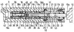
도 1은 본 발명에 따른 제동장치의 부분 절결 상태의 부분 단면도;1 is a partial cross-sectional view of a partially cutaway state of a braking device according to the present invention;
도 2는 제동장치가 정지 위치에 있고, 도 1의 요소 및 비상 보조 밸브의 큰 배율의 부분 단면도;FIG. 2 is a partial cross sectional view of a large magnification of the element and emergency aid valve of FIG.
도 3은 포화 후에 통상 제동 동안의 요소를 도 2와 동일한 방식으로 도시한 도면;3 shows the element during normal braking after saturation in the same manner as in FIG. 2;
도 4는 도 3에 도시된 상태 이후에 브레이크 페달이 해제되었을 때 비상 밸브 요소를 도 2와 동일한 방식으로 도시한 도면.4 shows the emergency valve element in the same manner as in FIG. 2 when the brake pedal is released after the state shown in FIG.
본 발명과 같은 타입의 배력식 제동장치의 전체적인 구조 및 일반적인 작동은, 특히 EP-B-0 662 894호 또는 FR-B-2 658 466호를 통해서 주지되어 있으므로, 간단하게 언급만 할 것이다. 보다 상세한 것은 상기 특허공보를 참조하기 바란다.The overall structure and general operation of a hydrostatic braking device of the type of the invention is well known, in particular through EP-B-0 662 894 or FR-B-2 658 466, which will therefore be briefly mentioned. See the above patent publication for more details.
도 1은 자동차용 제동장치(1)를 도시하고 있고, 부분적으로 도시된 마스터 실린더(2), 및 마스터 실린더(2) 내에서 미끄럼이동식으로 장착된 주 피스톤(3)을 포함한다. 주 피스톤(3)과 동축인 링크장치를 포함하는 수동 제어 부재(4)는, 후방으로부터 전방으로, 즉 도 1에서 우측으로부터 좌측으로, 입력 힘을 이 피스톤 상에 가하도록 설계되어 있다. 주 피스톤(3)의 전방 변위는, 적어도 하나의 유압 제동회로에 연결되어 있는, 마스터 실린더(2)의 내부 체적(5) 내에서의 액체의 압력의 증가를 야기한다. 일반적으로 제어 부재(4)는 개략적으로 도시된 브레이크 페달(4a)에 의해 작동된다.1 shows a braking device 1 for an automobile and includes a partially illustrated
공압 배력장치(6)는 제어 부재(4)에 연결되어 있다. 배력장치(6)는, 탄성중합체로 제작되는 다이어프램(8a)을 포함하는 가동 격벽(8)에 의해, 밀봉식으로 내부적으로 2개의 공압 챔버(7a, 7b)로 분할되는 강성 케이싱(7) 및 강성 스커트(8b)를 포함한다. 챔버(7a)는 노즐(A)에 의해 부분 진공원(도시 생략)에 상시 연결된다. 주 피스톤(3)과 동축인 슬리브 형태의 공압 피스톤(9)은 강성 스커트(8b)에 고정된다. 공압 피스톤(9)은 실린더형 코어의 형태인 플런저 디스트리뷰터(10) 상에서 밀봉식으로 미끄럼이동식으로 장착된다. 밀봉은 O-링(11)에 의해 가능하다.The pneumatic booster 6 is connected to the control member 4. The power booster 6 includes a rigid casing 7 which is internally divided into two
플런저(10)는, 소직경 확장부(10a)를 전방쪽에, 그리고 후방쪽으로 개방되어 있고, 링크장치(4)의 끝부에 구비된 보어 끝부(4b)를 수용하는, 축선방향의 블라인드 하우징(10b)을 후방쪽에 포함한다.The
피스톤(3)과는 반대쪽에, 플런저(10)는 공압 피스톤(9)에 축방향 이동에 의해 연결된 탄성중합체 링(13)에 대하여 밀봉식으로 지지할 수 있는 절단원추형 확대부(12)를 가지고 있다. 조립체(12, 13)는, 챔버(7b)를 대기로부터 단절하는 것 을 허용하고 챔버(7a, 7b)를 연통 상태에 있게 하는 것을 허용하거나, 챔버(7a, 7b)를 서로로부터 단절하는 것을 허용하고 확대부(12)가 링(13)으로부터 멀어지는 방향으로 축방향으로 이동할 때 대기압의 공기를 챔버(7b) 내로 허용하는, 3방향 밸브(B)(부분적으로 도시)의 부분을 구성한다.On the opposite side of the
공압 피스톤(9)은, 피스톤(9)과, 마스터 실린더(2)가 고정된 케이싱(7)에 대향하는 벽 사이에 위치하는 압축 스프링(14)에 의해, 도 1에 도시된 정지 위치를 향하여 복귀한다. 중앙 개구부(16)를 구비한 컵(15)은 공압 피스톤(9)의 어깨부에 기대어 있는 그 외부 외주 가장자리를 통하여 축방향으로 지지된다. 스프링(14)은 피스톤(9)에 대하여 이 컵의 가장자리를 가압한다. 컵(15)은 그 개구부(16)를 포위하는 내부 가장자리를 통하여 주 피스톤(3)의 후방 끝부에 대하여 축방향으로 지지된다. 플런저(10)의 확장부(10a)는 개구부(16)를 자유롭게 관통할 수 있다.The
통상 제동 및 비상 제동에 각각 상응하는 적어도 2개의 배력 비율의 조정을 시작하도록 비상 보조 밸브(VA)가 구비된다.Emergency assist valves VA are typically provided to initiate adjustment of at least two power ratios corresponding respectively to braking and emergency braking.
밸브(VA)는 소직경 전방부(17a)(도 2 참조)가 주 피스톤(3) 내의 축방향 보어(18) 내에서, O-링(17b)에 의해 밀봉식으로, 미끄럼이동하는 반동 피스톤(17)을 포함한다. 반동 피스톤의 후방부(17c)는 큰 직경을 가지고 있고 주 피스톤(3) 내의 보어(18)의 큰 직경 후방 영역 내에서 미끄럼이동할 수 있는 어깨부(19)를 가지고 있다. 탄성중합체로 제작된 링(20)은 부분(17a)과 같은 쪽에서 어깨부(19)에 대하여 위치한다. 이 링(20)은 주 피스톤(3)의 어깨부(21)에 대하여 축방향으로 지지될 수 있다. 반대 쪽에서, 어깨부(19)는 점프 스프링으로 알려져 있는 예하중 헬리컬 압축 스프링(22)을 위한 축방향 스러스트면으로 기능한다. 그 다른 쪽 후방 끝에서, 스프링(22)은, 주 피스톤(3)에 고정되고 반동 피스톤의 후방부(17c)가 내부에서 미끄럼이동하는 플라스틱제 클립 인(clip-in) 링(23)에 대하여 지지된다.The valve VA is a rebound piston in which a small
반동 피스톤(17)은, 피스톤을 통하여 축방향으로 통하는, 상이한 직경의 2개의 동축 연속 보어(24, 25)가 형성된 통로를 가지고 있다. 전방의 보어(24)는 후방의 보어(25)보다 큰 직경을 가지고 있고 하우징을 형성한다.The
비율 제어부(T)는 2개의 연속의 개별 요소(26, 27)로 이루어 지고, 피스톤(17) 내에 장착되어 있다.The ratio control part T consists of two consecutive
전방쪽의 제 1 요소(26)는 전방 끝부에서 보어(24)보다 큰 직경의 헤드(26a)를 포함한다. 헤드(26a)의 후방에 위치하는 요소(26)의 부분(26b)은 작은 직경과 보어(24)의 단면부에 상응하는 단면부(S2)를 가지고 있다. 이 부분(26b)은 보어 내의 그루브 내에 수납된 O-링(24a)에 의해 밀봉식으로 보어(24) 내에서 미끄럼이동할 수 있다. 헤드(26a)의 전방 끝부는, 전방으로 돌출하고, O-링(29)이 끼워져 있고 헤드926a)의 외측면 직경보다 작고 축에 중심이 맞추어져 있는 그루브가 있는, 볼록한 절단원추형 표면(28)을 가지고 있다. 요소(26)를 관통하여 축방향 덕트(30)가 있고, 그 전방 끝부(30a)는 작은 직경을 가지고 있다.The front
비율 제어부(T)의 후방 요소(27)는 전방 요소(26)와는 독립적이다. 단면부(S3)의 요소(27)는 보어(25)와 동일한 직경을 가지고 있고 이 보어 내부에서 요소(27)는 보어(25) 내의 그루브 내에 수납된 O-링(31)에 의해 밀봉식으로 미끄럼이동할 수 있다. 요소(27)의 전방 끝부는 보어924) 내로 돌출하고, 요소(27) 내의 그루브 내에 수납된 탄성 스냅 링(32), 즉 개방 링을 구비하고 있다. 이 스냅 링(32)은 보어(24)와 보어(25)의 전환점을 나타내는 어깨부(33)에 대한 스톱부로서 기능하여 요소(27)를 피스톤(17) 내에 유지할 수 있다. 요소(27)의 전방 끝부는 요소(26)의 후방 끝부와 어깨부(33) 사이에 있는 공간(34) 내에 위치한다. 요소(27)의 후방 끝부는 플런저(10)의 확장부(10a)에 대하여 지지된다. 요소(27)는 플런저(10)에 대하여, 단면부(S3) 상의 압력에 의해 야기되는 반동 부하를 전달한다.The
제 1 요소(26)의 헤드(26a)는, 반동 피스톤(17)과, 보어(18) 내에서 보다 더 전방에 수납된 부싱(36) 사이에 위치하는 보어(18)의 챔버(35) 내에 위치한다. 부싱(36)은 압력 끼워맞춤 또는 고정 탭에 의해 축방향으로 주 피스톤(3)에 대하여 고정된다.The
부싱(36)은, 부싱을 완전히 관통하고, 급속 피스톤(38)이 O-링(38a)에 의해 밀봉식으로 미끄럼이동식으로 장착된, 축방향 보어(37)를 가지고 있다. 급속 피스톤(38)의 외경은 반동 피스톤의 전방부(17a)의 외경보다 작다. 급속 피스톤(38)은, 급속 피스톤을 축방향으로 통하고, 각 끝부에서 개방된 통로(39)를 가지고 있다. 급속 피스톤(38)의 전방 끝부는 부싱(36)에 대하여 스프링(41)에 의해 눌려져 있는 링(40)에 대하여 지지된다. 스프링(41)은, 다른 끝부에서, 보어918)의 전방에 위치하는 끝벽(42)에 대하여 지지된다. 스프링(41)이 수납되어 있는 보어(18)의 전방 영역(18a)은 덕트(43)를 통하여 마스터 실린더(2)의 내부 체적(5)과 연통한다. 스프링(41)은 스프링(22)의 예하중보다 작은 예하중을 받는다. 체적(5)이 더 이상 압력하에 있지 않을 때, 이 체적이 저장소(도시 생략)로부터 액체가 재공급될 수 있도록 밸브(44)(도 1 참조)가 또한 구비된다.The
급속 피스톤(38)의 후방 끝부(45)는 챔버(35) 내에 위치하고 보어(37)의 직경보다 큰 직경의 디스크 형태이다. 이끝(45)은, 헤드(26a)의 절단원추형 표면(28) 및 O-링(29)과 협동하도록, 절단원추형 오목부(46)와 후방을 향해 면하는 오목측을 가진다. 따라서 밸브(C)는, 축방향으로 함께 지지될 때, 이동 피스톤(38)내의 챔버(35)와 통로(39)사이의 왕래를 단절하는 헤드(26a)와 디스크(45)에 의해 형성되어 있다. 밸브(C)의 폐쇄를 위한 단면은 비율 제어부의 요소(27)의 단면(S3)과 동등하다.The
동축 압축 스프링(47)은 헤드(26a)와 후방끝(45)에 각각 구비된 2개의 어깨부사이에 위치되어 있다. 이 스프링(47)은 밸브(C)를 개방하기 위해서 끝(45)과 헤드(26a)가 이격되게 하는 경향이 있다.The
제동장치의 "포화"지점은 배력장치(6)가 제공할 수 있는 배력이 최대에 도달할 때에 이르게 되며, 즉 격벽(8)이 받기쉬운 압력차이가 그 이상 증대하지않을 때이다.The "saturation" point of the braking device is reached when the power up to which the power supply 6 can provide reaches its maximum, that is, when the pressure difference that the partition 8 is likely to receive no longer increases.
이것이 발생될 때, 제동과 포화상태가 지나친 후 제동페달이 이완될 때, 제동장치의 작동은 다음과 같이 된다.When this occurs, when the brake pedal is relaxed after the braking and saturation have passed, the operation of the braking device becomes:
이어서, 슬로우 제동에 관하여 설명한다. 수동 제어부재(4)는 페달(4a)을 밟으므로서 좌측으로 이동한다. 밸브(B)는 작동되어 챔버(7a)와 챔버(7b)사이의 왕래를 단절하고, 절단원추형 확대부(12)는 링(13)으로부터 이동되고, 대기압상태 의 공기는 배력장치(6)의 챔버(7b)내로 들어가게 된다. 이동 격벽(8)은 배력을, 스프링(14)에 저항하여 전방으로 이동하는 유압피스톤(9)에 전달한다. 피스톤(9)은 주 피스톤(3)을 전방으로 미는 컵(15)을 구동한다. 플런저(10)도 전방으로 밀고, 연장부(10a)를 거쳐서 그 전방끝을 거쳐서 요소(26)의 후방끝에 대하여 맞닿게 되는 요소(27)를 밀고 따라서 요소(26)는 요소(27)에 의해 밀린다. 주 피스톤(3)과 비율 제어부(T)를 형성하는 조립체(26,27)는 전방으로 이동하고, 밸브(C)는 개방상태로 있다.Next, slow braking will be described. The manual control member 4 moves to the left while pressing the pedal 4a. The valve B is actuated to break the traffic between the chamber 7a and the
다량의 액체(5)의 압력은, 주 피스톤(3)이 마스터 실린더(2)내로 들어가기 때문에 증대한다. 이 압력의 증대는 챔버(35)에 전달되어, 밸브(C)는 개방된다. 압력은 반동 피스톤(17)에 작용하여 부하를 후방으로 민다. 이 부하가 스프링(22)의 초기부하에 도달하고 초과할 때, 반동 피스톤(17)은 연장부(10a)에 대하여 맞닿기 까지 후퇴되며, "점프"로 알려진 단계에 해당한다.The pressure of the large amount of
이 구성(도시생략)에서 어깨부(19)와 링(20)은 어깨부(21)로부터 약간 이격된다.In this configuration (not shown), the
부재(4)상의 입력작용하에서, 플런저(10)는 그 전방이동을 계속하고; 유압피스톤(9)은 플런저(10)를 따라가고 배력을 가지고 주 피스톤(9)을 민다.Under the input action on the member 4, the
체적(5)내의 액체의 압력은 챔버(35)내에서와 같이 계속 증대된다.The pressure of the liquid in the
배력장치(6)의 챔버(7b)와 챔버(7a)사이의 압력차이가 최대치에 도달할 때, 배력장치(6)는 "포화"에 해당하는 그 최대하중을 발생한다. 제동효과의 증대는 부재(4)상에 입력을 증대시키므로써만 얻을 수 있다. 주 피스톤(3)은, 이 피스톤(3) 상의 액체의 압력에 의해 후방으로 가해진 힘이 배력장치(6)의 배력과 균형되기 때문에, 짧은 기간 고정상태로 있다.When the pressure difference between the
제어부재(4)가 수동력의 작동하에 계속해서 전진함으로, 비율 제어부(T)는 주 피스톤(3)에 비례하에 전진한다. 요소(27)는, 헤드(26a)가 시트(46)에 대하여 실링부(29)를 거쳐 밀봉방식으로 눌러 요소(26)를 누른다. 그러면, 밸브(C)는 폐쇄된다. 급속 피스톤(38)은 헤드(26a)에 의해 전방으로 눌려 있고, 피스톤 자체는 스프링(41)의 작용에 대하여 부싱(36)으로부터 이격되는 링(40)을 누른다. 반동 피스톤(17)은 지지하는 플런저(10)에 의해 눌리고, 또한 도 3에 도시된 바와같이 링(20)이 어깨부(21)와 맞닿게 되기까지 주 피스톤(3)에 비례해서 전진한다.As the control member 4 continues to advance under the operation of the manual force, the ratio controller T advances in proportion to the
제어부재(4)상의 입력은 반동 피스톤(17)을 거쳐 주 피스톤(3)이 구동되고, 제동압력이 포화지점을 넘어서 증대될 수 있게 한다.The input on the control member 4 allows the
포화지점을 넘어서 슬로우 제동단계에 이어서, 제동페달(4a)이 해제되었을 때, 제어부재(4)와 플런저(10)는 후퇴되며, 즉 유압작용하에 도면에 도시된 바와같이 우측으로 이동한다. 주 피스톤(3) 역시 후퇴하지만, 피스톤(3)의 이동은 간소와의 이유로 도 2 내지 도 4에 설명이 생략되었다.Following the slow braking step beyond the saturation point, when the brake pedal 4a is released, the control member 4 and the
급속 피스톤(38)은, 부싱(36)에 대하여 전진되었으며, 요소(26)가 챔버(41)내에서 얻은 압력효과하에 있는 것과 같이 후퇴이동(도 4참조)하고, 급속 피스톤(38)의 단면(S1)에 적용되어 있다. 반동 피스톤(17)은, 이 잠재압력의 효과와 스프링(22)의 힘이 균형되게 도달하는 위치까지 챔버(35)내에서 트랩상태의 잠재압력효과하에 작은 후방 변위를 경험하고; 피스톤(17)의 후방끝은, 플런저(10)의 연장부(10a)와의 접촉을 단절 피스톤(17)보다 더 후퇴한다(도 4).The
마스터 실린더와 챔버(41)내의 압력은 주 피스톤(3)이 후방으로 이동할수록 감소한다. 그러나 챔버(41)내의 압력은 폐쇄밸브(C)에 의해 격리되어 있는 챔버(35)내에서 얻은 압력보다 높은대로 남아 있다.The pressure in the master cylinder and
챔버(35)내의 압력보다 높은 챔버(41)내의 압력의 어떤 값을 넘어서, 밸브(C)의 스프링(47)의 힘은 현저하게 되고, 본 발명의 배열내에 없는 밸브(C)를 개방할 수도 있다.Beyond a certain value of the pressure in the
그러한 개방은 챔버(35)내의 압력을 예리하게 증대시키게 할 수도 있으며 반동 피스톤(17)의 예리한 후퇴를 증대시킬 수도 있고, 충격음으러서 플런저(10)의 연장부(10a)와 충돌할 수도 있다.Such an opening may sharply increase the pressure in the
본 발명의 배열은 이 소음을 배제할 수 있다.The arrangement of the present invention can eliminate this noise.
챔버(41)내에서 얻은 압력은 통로(39,30)에 의해 공간(34)으로 전달되었다. 밸브(C)의 폐쇄를 위한 단면보다 큰 단면(S2)을 넘어서 요소(26)의 후방에 대한 이압력의 적용은 스프링(47)의 힘을 방해할 수 있게 하며, 챔버(41)내의 압력이 비교적 낮은 값으로 떨어지기까지 밸브(C)를 계속 폐쇄할 수 있게한다.The pressure obtained in
밸브(C)가 개방되었을 때, 챔버(35)에 전달된 챔버(41)내의 압력은 낮고, 반동 피스톤(17)은 플런저(17)에 대항하여 예리하게 복귀하지않는다. 이 압력의 값은, 스프링(22)의 힘보다 크지않은 피스톤(17)상에 발생된 힘보다 충분히 낮기까지도 하여, 피스톤(17)은 뒤로 밀리지않는다.When the valve C is open, the pressure in the
따라서 요소(26,27)로 형성된 수단, 통로(30) 및 공간(34)은 반동 피스톤(17)의 예리한 후퇴를 막는 한편, 챔버(35)내의 압력의 증대를 한정한다. 물론 청구된 보호범위는 설명된 내용과 동일한 모든 수단을 포함한다.
The means,
Claims (17)
Translated fromKoreanApplications Claiming Priority (2)
| Application Number | Priority Date | Filing Date | Title |
|---|---|---|---|
| FR0015304AFR2817221B1 (en) | 2000-11-24 | 2000-11-24 | ASSISTED BRAKING DEVICE WITH IMPROVED OPERATION FOR A MOTOR VEHICLE |
| FR00/15304 | 2000-11-24 |
Publications (2)
| Publication Number | Publication Date |
|---|---|
| KR20020070513A KR20020070513A (en) | 2002-09-09 |
| KR100784329B1true KR100784329B1 (en) | 2007-12-13 |
Family
ID=8856924
Family Applications (1)
| Application Number | Title | Priority Date | Filing Date |
|---|---|---|---|
| KR1020027009508AExpired - Fee RelatedKR100784329B1 (en) | 2000-11-24 | 2001-11-21 | Braking booster with improved operation for the vehicle |
Country Status (12)
| Country | Link |
|---|---|
| US (1) | US6718765B2 (en) |
| EP (1) | EP1339584B1 (en) |
| JP (1) | JP4298290B2 (en) |
| KR (1) | KR100784329B1 (en) |
| CN (1) | CN1213890C (en) |
| AT (1) | ATE387358T1 (en) |
| AU (2) | AU2081202A (en) |
| BR (1) | BRPI0109178A2 (en) |
| DE (1) | DE60133031D1 (en) |
| FR (1) | FR2817221B1 (en) |
| RU (1) | RU2273571C2 (en) |
| WO (1) | WO2002042140A1 (en) |
Families Citing this family (3)
| Publication number | Priority date | Publication date | Assignee | Title |
|---|---|---|---|---|
| FR2817224B1 (en)* | 2000-11-29 | 2003-01-10 | Bosch Gmbh Robert | ASSISTED BRAKING DEVICE FOR A MOTOR VEHICLE |
| CN101769383A (en)* | 2010-04-13 | 2010-07-07 | 瑞安市良精石化机械厂 | Power-assisted cut-off device |
| KR101402712B1 (en)* | 2010-05-12 | 2014-06-11 | 주식회사 만도 | Hydraulic brake booster |
Citations (3)
| Publication number | Priority date | Publication date | Assignee | Title |
|---|---|---|---|---|
| FR2658466A1 (en)* | 1990-02-21 | 1991-08-23 | Bendix Europ Services Tech | ASSEMBLY OF A BRAKE ASSIST MOTOR AND A MASTER CYLINDER. |
| US5921084A (en) | 1996-07-23 | 1999-07-13 | Robert Bosch Technology Corporation | Power-assisted braking device with a variable assistance ratio |
| FR2784953A1 (en)* | 1998-10-26 | 2000-04-28 | Bosch Syst Freinage | Brake master cylinder with dynamically adjustable hydraulic reaction, comprises an axial pin mounted on the master cylinder controlling the axial passage |
Family Cites Families (8)
| Publication number | Priority date | Publication date | Assignee | Title |
|---|---|---|---|---|
| RU2041090C1 (en)* | 1989-08-09 | 1995-08-09 | Лукас Индастриз Паблик Лимитед Компани | Vehicle brake system and hydraulic brake system |
| JP3393256B2 (en) | 1992-09-30 | 2003-04-07 | アライドシグナル ウーロープ セルビス テクニック | Brake booster device with delayed fluid reaction force |
| DE4429439C2 (en)* | 1994-08-19 | 1998-07-02 | Lucas Ind Plc | Master brake cylinder |
| FR2724354A1 (en)* | 1994-09-08 | 1996-03-15 | Alliedsignal Europ Services | ASSISTED BRAKING DEVICE WITH MASKED TRAVEL AND INCREASED SAFETY |
| FR2731669B1 (en)* | 1995-03-17 | 1997-05-16 | Alliedsignal Europ Services | SERVOMOTOR WITH PRE-FILLING WITHOUT FLOW LIMITATION |
| FR2752210B1 (en)* | 1996-08-09 | 1998-09-18 | Bosch Sist De Frenado Sl | ASSISTED BRAKING DEVICE WITH HYDRAULIC REACTION AND INCREASED SAFETY |
| FR2756240B1 (en)* | 1996-11-22 | 1998-12-31 | Bosch Sist De Frenado Sl | ASSISTED BRAKING DEVICE WITH A VARIABLE ASSISTANCE RATIO AND REDUCED HYSTERESIS |
| FR2765173B1 (en)* | 1997-06-27 | 1999-08-27 | Bosch Sist De Frenado Sl | DYNAMIC HYDRAULIC REACTION MASTER CYLINDER WITH FLOATING PISTON |
- 2000
- 2000-11-24FRFR0015304Apatent/FR2817221B1/ennot_activeExpired - Fee Related
- 2001
- 2001-11-21JPJP2002544293Apatent/JP4298290B2/ennot_activeExpired - Fee Related
- 2001-11-21RURU2003117469/11Apatent/RU2273571C2/ennot_activeIP Right Cessation
- 2001-11-21KRKR1020027009508Apatent/KR100784329B1/ennot_activeExpired - Fee Related
- 2001-11-21BRBRPI0109178-6Apatent/BRPI0109178A2/ennot_activeApplication Discontinuation
- 2001-11-21AUAU2081202Apatent/AU2081202A/enactivePending
- 2001-11-21WOPCT/FR2001/003655patent/WO2002042140A1/enactiveIP Right Grant
- 2001-11-21DEDE60133031Tpatent/DE60133031D1/ennot_activeExpired - Lifetime
- 2001-11-21EPEP01997431Apatent/EP1339584B1/ennot_activeExpired - Lifetime
- 2001-11-21USUS10/111,019patent/US6718765B2/ennot_activeExpired - Lifetime
- 2001-11-21CNCNB018055702Apatent/CN1213890C/ennot_activeExpired - Fee Related
- 2001-11-21AUAU2002220812Apatent/AU2002220812B2/ennot_activeCeased
- 2001-11-21ATAT01997431Tpatent/ATE387358T1/ennot_activeIP Right Cessation
Patent Citations (3)
| Publication number | Priority date | Publication date | Assignee | Title |
|---|---|---|---|---|
| FR2658466A1 (en)* | 1990-02-21 | 1991-08-23 | Bendix Europ Services Tech | ASSEMBLY OF A BRAKE ASSIST MOTOR AND A MASTER CYLINDER. |
| US5921084A (en) | 1996-07-23 | 1999-07-13 | Robert Bosch Technology Corporation | Power-assisted braking device with a variable assistance ratio |
| FR2784953A1 (en)* | 1998-10-26 | 2000-04-28 | Bosch Syst Freinage | Brake master cylinder with dynamically adjustable hydraulic reaction, comprises an axial pin mounted on the master cylinder controlling the axial passage |
Also Published As
| Publication number | Publication date |
|---|---|
| CN1406188A (en) | 2003-03-26 |
| RU2003117469A (en) | 2005-01-10 |
| JP2004514584A (en) | 2004-05-20 |
| CN1213890C (en) | 2005-08-10 |
| EP1339584B1 (en) | 2008-02-27 |
| BRPI0109178A2 (en) | 2019-04-16 |
| US6718765B2 (en) | 2004-04-13 |
| JP4298290B2 (en) | 2009-07-15 |
| EP1339584A1 (en) | 2003-09-03 |
| FR2817221B1 (en) | 2003-01-10 |
| AU2002220812B2 (en) | 2006-07-06 |
| ATE387358T1 (en) | 2008-03-15 |
| KR20020070513A (en) | 2002-09-09 |
| RU2273571C2 (en) | 2006-04-10 |
| AU2081202A (en) | 2002-06-03 |
| US20030038004A1 (en) | 2003-02-27 |
| WO2002042140A1 (en) | 2002-05-30 |
| FR2817221A1 (en) | 2002-05-31 |
| DE60133031D1 (en) | 2008-04-10 |
Similar Documents
| Publication | Publication Date | Title |
|---|---|---|
| US4433543A (en) | Power-operated boosters | |
| KR100298465B1 (en) | Step-up brake system with concealed movement | |
| KR100943853B1 (en) | Pneumatic brake booster | |
| JPH0313105B2 (en) | ||
| EP0296614B1 (en) | Hydraulic booster | |
| JPS5835892B2 (en) | power brake unit | |
| PL184053B1 (en) | Power braking device with variable power ratio and reduced hysteresis | |
| KR100784329B1 (en) | Braking booster with improved operation for the vehicle | |
| KR100822267B1 (en) | Booster Type Braking System | |
| US6273526B1 (en) | Fluid pressure booster and brake system using the same | |
| JP2002308085A (en) | Hydraulic booster | |
| US6561075B2 (en) | Power booster with mechanical panic assist function | |
| KR20000029871A (en) | Power braking device with hydraulic reaction and increased safety | |
| JP3887262B2 (en) | Brake hydraulic pressure control device for vehicles | |
| GB2077375A (en) | Improvements in power- operated boosters | |
| JP2660264B2 (en) | Hydraulic brake device | |
| JP2581951B2 (en) | Hydraulic booster | |
| KR20020070512A (en) | Brake booster device with emergency valve | |
| JPS6220932B2 (en) | ||
| KR100341292B1 (en) | Brake system | |
| JPH01141157A (en) | Hydraulic booster | |
| KR20090057062A (en) | Negative pressure booster and brake booster using it | |
| JP2001287636A (en) | Brake system | |
| JPH02204157A (en) | Hydraulic booster | |
| JPH0495558A (en) | Boost hydraulic pressure output device |
Legal Events
| Date | Code | Title | Description |
|---|---|---|---|
| PA0105 | International application | St.27 status event code:A-0-1-A10-A15-nap-PA0105 | |
| PG1501 | Laying open of application | St.27 status event code:A-1-1-Q10-Q12-nap-PG1501 | |
| A201 | Request for examination | ||
| PA0201 | Request for examination | St.27 status event code:A-1-2-D10-D11-exm-PA0201 | |
| R17-X000 | Change to representative recorded | St.27 status event code:A-3-3-R10-R17-oth-X000 | |
| R18-X000 | Changes to party contact information recorded | St.27 status event code:A-3-3-R10-R18-oth-X000 | |
| E701 | Decision to grant or registration of patent right | ||
| PE0701 | Decision of registration | St.27 status event code:A-1-2-D10-D22-exm-PE0701 | |
| GRNT | Written decision to grant | ||
| PR0701 | Registration of establishment | St.27 status event code:A-2-4-F10-F11-exm-PR0701 | |
| PR1002 | Payment of registration fee | St.27 status event code:A-2-2-U10-U12-oth-PR1002 Fee payment year number:1 | |
| PG1601 | Publication of registration | St.27 status event code:A-4-4-Q10-Q13-nap-PG1601 | |
| R18-X000 | Changes to party contact information recorded | St.27 status event code:A-5-5-R10-R18-oth-X000 | |
| PR1001 | Payment of annual fee | St.27 status event code:A-4-4-U10-U11-oth-PR1001 Fee payment year number:4 | |
| R18-X000 | Changes to party contact information recorded | St.27 status event code:A-5-5-R10-R18-oth-X000 | |
| PR1001 | Payment of annual fee | St.27 status event code:A-4-4-U10-U11-oth-PR1001 Fee payment year number:5 | |
| FPAY | Annual fee payment | Payment date:20121127 Year of fee payment:6 | |
| PR1001 | Payment of annual fee | St.27 status event code:A-4-4-U10-U11-oth-PR1001 Fee payment year number:6 | |
| FPAY | Annual fee payment | Payment date:20131122 Year of fee payment:7 | |
| PR1001 | Payment of annual fee | St.27 status event code:A-4-4-U10-U11-oth-PR1001 Fee payment year number:7 | |
| FPAY | Annual fee payment | Payment date:20141128 Year of fee payment:8 | |
| PR1001 | Payment of annual fee | St.27 status event code:A-4-4-U10-U11-oth-PR1001 Fee payment year number:8 | |
| PR1001 | Payment of annual fee | St.27 status event code:A-4-4-U10-U11-oth-PR1001 Fee payment year number:9 | |
| R18-X000 | Changes to party contact information recorded | St.27 status event code:A-5-5-R10-R18-oth-X000 | |
| R18-X000 | Changes to party contact information recorded | St.27 status event code:A-5-5-R10-R18-oth-X000 | |
| FPAY | Annual fee payment | Payment date:20161201 Year of fee payment:10 | |
| PR1001 | Payment of annual fee | St.27 status event code:A-4-4-U10-U11-oth-PR1001 Fee payment year number:10 | |
| FPAY | Annual fee payment | Payment date:20171129 Year of fee payment:11 | |
| PR1001 | Payment of annual fee | St.27 status event code:A-4-4-U10-U11-oth-PR1001 Fee payment year number:11 | |
| FPAY | Annual fee payment | Payment date:20181127 Year of fee payment:12 | |
| PR1001 | Payment of annual fee | St.27 status event code:A-4-4-U10-U11-oth-PR1001 Fee payment year number:12 | |
| PC1903 | Unpaid annual fee | St.27 status event code:A-4-4-U10-U13-oth-PC1903 Not in force date:20191205 Payment event data comment text:Termination Category : DEFAULT_OF_REGISTRATION_FEE | |
| PC1903 | Unpaid annual fee | St.27 status event code:N-4-6-H10-H13-oth-PC1903 Ip right cessation event data comment text:Termination Category : DEFAULT_OF_REGISTRATION_FEE Not in force date:20191205 |