KR100783171B1 - Display device - Google Patents
Display deviceDownload PDFInfo
- Publication number
- KR100783171B1 KR100783171B1KR1020010020871AKR20010020871AKR100783171B1KR 100783171 B1KR100783171 B1KR 100783171B1KR 1020010020871 AKR1020010020871 AKR 1020010020871AKR 20010020871 AKR20010020871 AKR 20010020871AKR 100783171 B1KR100783171 B1KR 100783171B1
- Authority
- KR
- South Korea
- Prior art keywords
- support
- ray tube
- cathode ray
- side wall
- substrate frame
- Prior art date
- Legal status (The legal status is an assumption and is not a legal conclusion. Google has not performed a legal analysis and makes no representation as to the accuracy of the status listed.)
- Expired - Fee Related
Links
Images


Classifications
- H—ELECTRICITY
- H04—ELECTRIC COMMUNICATION TECHNIQUE
- H04N—PICTORIAL COMMUNICATION, e.g. TELEVISION
- H04N5/00—Details of television systems
- H04N5/64—Constructional details of receivers, e.g. cabinets or dust covers
- H—ELECTRICITY
- H04—ELECTRIC COMMUNICATION TECHNIQUE
- H04N—PICTORIAL COMMUNICATION, e.g. TELEVISION
- H04N5/00—Details of television systems
- H04N5/64—Constructional details of receivers, e.g. cabinets or dust covers
- H04N5/645—Mounting of picture tube on chassis or in housing
- G—PHYSICS
- G06—COMPUTING OR CALCULATING; COUNTING
- G06F—ELECTRIC DIGITAL DATA PROCESSING
- G06F1/00—Details not covered by groups G06F3/00 - G06F13/00 and G06F21/00
- G06F1/16—Constructional details or arrangements
- G06F1/1601—Constructional details related to the housing of computer displays, e.g. of CRT monitors, of flat displays
Landscapes
- Engineering & Computer Science (AREA)
- General Engineering & Computer Science (AREA)
- Theoretical Computer Science (AREA)
- Multimedia (AREA)
- Signal Processing (AREA)
- Computer Hardware Design (AREA)
- Human Computer Interaction (AREA)
- Physics & Mathematics (AREA)
- General Physics & Mathematics (AREA)
- Video Image Reproduction Devices For Color Tv Systems (AREA)
- Devices For Indicating Variable Information By Combining Individual Elements (AREA)
Abstract
Translated fromKorean
Description
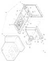
Translated fromKorean도 1은 본 발명에 따른 디스플레이장치의 분해사시도,1 is an exploded perspective view of a display device according to the present invention;
도 2는 도 1의 기판프레임 설치영역의 부분확대사시도,2 is an enlarged perspective view of a portion of the substrate frame installation region of FIG.
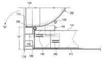
도 3 내지 도 5는 도 1 및 도 2의 기판프레임 설치 순서를 설명하기 위한 부분확대단면도,3 to 5 is a partially enlarged cross-sectional view for explaining the installation sequence of the substrate frame of FIGS.
도 6는 종래 디스플레이장치의 분해사시도,6 is an exploded perspective view of a conventional display device;
도 7는 도 6의 기판프레임 설치영역의 부분확대사시도,7 is an enlarged perspective view of a portion of the substrate frame installation area of FIG.
도 8 내지 도 9은 도 6 및 도 7의 기판프레임 설치 순서를 설명하기 위한 부분확대단면도이다.8 to 9 are partially enlarged cross-sectional views for explaining a substrate frame installation procedure of FIGS. 6 and 7.
* 도면의 주요 부분에 대한 부호의 설명* Explanation of symbols for the main parts of the drawings
5 : 음극선관조립체 7 : 메인기판 5 cathode
10 : 전면케이싱 20 : 음극선관10: front casing 20: cathode ray tube
35 : 디가우징코일 40 : 기판프레임35: degaussing coil 40: substrate frame
43 : 상부돌기 45 : 하부돌기43: upper projection 45: lower projection
50 : 프레임지지부 51 : 측벽지지부50
53 : 하부지지부 55 : 하부가이드홈53: lower support portion 55: lower guide groove
57 : 가이드레일 60 : 음극선관지지부57: guide rail 60: cathode ray tube support
61 : 코일가이드벽 70 : 지지홀더61: coil guide wall 70: support holder
73 : 상부가이드홈 75 : 코일파지부73: upper guide groove 75: coil holding part
77 : 레일그루브 78 : 음극선관보조지지부77: rail groove 78: cathode ray tube auxiliary support
79 : 코일수용부 80 : 홀더고정부79: coil receiving portion 80: holder fixing
본 발명은, 디스플레이장치에 관한 것으로서, 보다 상세하게는 기판프레임 설치영역의 구조가 개선된 디스플레이장치에 관한 것이다.The present invention relates to a display apparatus, and more particularly, to a display apparatus having an improved structure of a substrate frame installation area.
디스플레이장치란 TV나 컴퓨터용 모니터를 통틀어 일컫는 말로써, 일반적으로 CRT모니터와 LCD모니터 등을 포함한다.The display device is a general term for a TV or a computer monitor, and generally includes a CRT monitor and an LCD monitor.
CRT모니터는, 음극선관(CRT)을 사용해서 영상신호의 세기에 따라 각기 다른 양의 전자빔이 CRT의 표면에 입혀진 단색 또는 RGB(Red, Green, Blue)의 형광물질을 타격하여 각기 다른 밝기나 색깔의 빛을 내게 만드는 원리를 이용한 것으로, 가격이 저렴하다는 장점이 있지만, 그 부피가 커서 공간활용도가 떨어지는 단점을 가지고 있다. 이에 최근에는 음극선관을 사용하는 디스플레이장치의 외관의 부피를 최소화하는 기술이 지속적으로 개발되고 있는 실정이다.The CRT monitor uses a cathode ray tube (CRT) to blow different amounts of electron beams onto the surface of the CRT, depending on the intensity of the image signal, or to hit the solid color or RGB (Red, Green, Blue) phosphors. It uses the principle of making the light of light, but it has the advantage of being cheaper, but it has a disadvantage that the space utilization is large due to its large volume. Recently, a technology for minimizing the volume of the appearance of a display device using a cathode ray tube has been continuously developed.
도 6는 종래 디스플레이장치의 분해사시도이고, 도 7는 도 6의 기판프레임 설치영역의 부분확대사시도이다. 이들 도면에 도시된 바와 같이, 종래 디스플레이장치(101)는, 외관을 형성하는 케이싱(103)과, 케이싱(103)내에 수용되는 음극선관조립체(105)를 가지고 있으며, 음극선관조립체(105)로 전기적신호를 전달하는 메인기판(107)과, 메인기판(107)을 지지하는 기판프레임(140)을 포함한다.6 is an exploded perspective view of a conventional display apparatus, and FIG. 7 is a partially enlarged perspective view of the substrate frame installation region of FIG. 6. As shown in these figures, the
케이싱(103)은 상호 결합에 의해 음극선관조립체(105) 및 메인기판(107) 등의 부품수용공간을 형성하는 전면케이싱(110)과 후면케이싱(111)으로 이루어져 있다. 전면케이싱(110)에는 음극선관(120)의 패널부 전면에 표시되는 영상이 외부로 전달될 수 있도록 사각형상의 투시개구(113)가 형성되어 있다. 그리고, 전면케이싱(110) 배면의 내측 각 모서리에는 음극선관조립체(105)의 결합을 위한 암나사부(117)를 갖는 음극선관결합부(115)가 마련되어 있다. 또한, 전면케이싱(110)의 배면 하부 양측에는 음극선관결합부(115)와 인접하게 배치되어음극선관(120)의 전방 하단부를 지지하는 한쌍의 음극선관지지부(160) 및 기판프레임(140)의 결합을 위한 프레임지지부(150)가 마련되어 있다.The
프레임지지부(150)는 기판프레임(140)의 양측벽(141) 전방영역을 지지하도록 음극선관지지부(160)의 하부로부터 후방으로 연장된 한 쌍의 측벽지지부(151)와, 양 측벽지지부(151)를 연결하며 기판프레임(140)의 전방영역의 하부면을 지지하는 하부지지부(153)를 갖는다.The
양 측벽지지부(151)의 상호 대향하는 내측벽 후방영역에는 후술할 기판프레임(140)의 양측벽(141)에 형성되어 있는 복수의 걸림돌기(143)가 슬라이딩 삽입되는 복수의 가이드홈(155)이 상호 평행하게 형성되어 있다.A plurality of guide grooves 155 in which a plurality of
음극선관조립체(105)는 음극선관(120)과, 음극선관(120)의 후단부영역에 결합되는 전자총 및 비디오장치(121)를 가지고 있다. 그리고, 음극선관(120)의 상부 및 하부에는 음극선관(120) 및 주변부품들로부터 발생되는 자력을 제거하여 패널에 표시되는 화면을 안정시키는 디가우징코일(135)(Degaussin Coil)이 마련되어 있다. 이 음극선관조립체(105)는 음극선관(120)의 전방 둘레에 결합된 금속재의 결합밴드(123)에 의해 전면케이싱(110)에 결합된다. 이를 위해 결합밴드(123)의 각 모서리영역에는 음극선관조립체(105)가 전면케이싱(110)에 결합될 수 있도록 스크류통과공(127)을 갖는 결합편(125)이 외향 돌출되어 있다.The cathode
기판프레임(140)은 메인기판(107)을 수용할 수 있도록 둘레외벽을 갖는 사각트레이형상으로 되어 있다. 그리고, 기판프레임(140)의 전방영역 양측벽(141)에는 프레임지지부(150)의 측벽지지부(151)에 형성된 복수의 가이드홈(155)에 삽입되는 복수의 삽입돌기(143)가 형성되어 있다. 이 기판프레임(140)의 양측벽(141)에 형성되어 있는 삽입돌기(143)들이 측벽지지부(151)의 가이드홈(155)에 슬라이딩 삽입됨으로써, 기판프레임(140)은 전면케이싱(110)에 대해 직교방향으로 수평 결합된다.The
양 측벽지지부(151)의 상부에는 음극선관(120)의 하부에 배치된 디가우징코일(135)의 양측부를 위치고정시키는 한편, 음극선관(120)의 펀넬부위 일영역을 지지하는 지지홀더(170)가 결합되어 있다. 이 지지홀더(170)는 측벽지지부(151)에 착탈가능하게 결합되는데, 이를 위해서, 지지홀더(170)의 하부 외측에는 측벽지지부(151)와의 결합을 위한 "⊃"자형상의 걸림부(177)가 형성되어 있고, 측벽지지부(151)의 상부 외측에는 걸림부(177)의 내측에 삽입되는 가이드돌기(157)와, 걸림부(177)의 외측을 지지하는 역"ㄴ"자 형상의 안내가이드(158)가 형성되어 있다.Both sides of the
그리고, 지지홀더(170)의 상부 외측에는 디가우징코일(135)의 양측부를 위치고정하기 위한 "ㄴ"자 형상의 코일수용부(179)가 형성되어 있다. 이 코일수용부(179)는 지지홀더(170)의 외측으로부터 연장되어 지지홀더(170)의 외측벽과 함께 "∪"자형상의 수용홈을 형성한다. 한편, 기판프레임(140)의 전방벽 상단부에는 음극선관(120)의 하단부에 길이방향을 따라 배치되는 디가우징코일(135)의 일구간을 파지하는 코일밴드(147)가 결합되어 있다.In addition, a
또한, 측벽지지부(151)와 지지홀더(170)에는 상호 맞물림 결합됨으로써, 지지홀더(170)의 유동을 방지하는 홀더고정부가 형성되어 있다. 홀더고정부는 지지홀더(170)의 하부에 형성된 걸림공(181)과, 측벽지지부(151)의 상부에 탄성변형 가능하게 형성된 걸림후크(183)로 이루어져 있다(도 8참조).In addition, the
그런데, 이러한 종래의 디스플레이장치에 있어서는, 기판프레임(140)이 도 8 및 도 9에 도시된 바와 같이, 전면케이싱(110)의 배면 하부에 형성된 프레임지지부(150)에 수평으로 결합되기 때문에, 디스플레이장치의 크기를 줄이는데 한계가 있다. 즉, 기판프레임(140)이 전면케이싱(110)과 직교하여 수평으로 결합됨으로써, 배면커버(111)의 상하방향 높이를 축소하는데 한계가 있는 것이다.However, in such a conventional display device, since the
그리고, 기판프레임(140)이 수평을 유지하며 전면케이싱(110)에 안정적으로 결합되기 위해서는, 프레임지지부(150)의 측벽지지부(151)에 복수의 가이드홈(155)을 형성하고 기판프레임(140)의 양측벽(141)에 가이드홈(155)에 대응하는 수만큼 삽입돌기(143)를 형성해야 하기 때문에, 측벽지지부(151)의 상하높이와 기판프레임(140)의 측벽(141) 크기가 비교적 크게 형성된다. 이에 의해, 전면케이싱(110)의 하부영역과 배면커버(111)의 하부영역에 기판프레임(140)의 장착을 위한 충분한 공간이 확보되어야 하므로 디스플레이장치의 부피(도 8 및 도 9의 표시부"C")가 커지는 문제점이 발생한다.In addition, in order for the
또한, 음극선관(120)의 하부에 배치되는 디가우징코일(135)이 측벽지지부(151) 상부에 결합되는 지지홀더(170)의 상부에 형성된 코일수용부(179)와, 기판프레임(140)의 전방벽 상단부에 결합되는 코일밴드(147)에 의해 위치고정되기 때문에, 디가우징코일(135)은 기판프레임(140)의 상부영역에서 위치고정된다. 이를 위한 공간을 확보하기 위해서 디스플레이장치의 부피가 커지는 문제점이 발생된다.In addition, the
또한, 이러한 종래의 디스플레이장치는, 기판프레임(140)이 전면케이싱(110)에 대해 직교하는 수평으로 결합되기 때문에, 음극선관(120)과 기판프레임(140)이 전면케이싱(110)에 결합된 부조립체(subassembly)가 다음의 조립공정에서 음극선관의 무게에 의해 전방으로(도 9의 표시부 "D" 방향) 전도될 우려가 크다는 문제점이 있다.In addition, since the
따라서, 본 발명의 목적은, 외관의 부피를 최소화할 수 있으며, 조립공정에서 전방으로 전도되는 것을 방지할 수 있는 디스플레이장치를 제공하는 것이다.Accordingly, it is an object of the present invention to provide a display device that can minimize the volume of the appearance and can prevent it from falling forward in the assembly process.
상기 목적은, 본 발명에 따라, 전면케이싱과, 상기 전면케이싱의 배면에 결합되는 음극선관과, 상기 음극선관의 하부에 배치되어 상기 음극선관으로 전기적 신호를 전달하는 메인기판을 갖는 디스플레이장치에 있어서, 상기 메인기판을 수용하는 기판프레임과; 상기 전면케이싱의 배면으로부터 가로방향으로 형성되어 상기 기판프레임을 후방으로 갈수록 상향 경사각을 갖도록 지지하는 프레임지지부를 포함하는 것을 특징으로 하는 디스플레이장치에 의해서 달성된다.According to the present invention, there is provided a display apparatus having a front casing, a cathode ray tube coupled to a rear surface of the front casing, and a main substrate disposed under the cathode ray tube to transmit an electrical signal to the cathode ray tube. A substrate frame accommodating the main substrate; It is achieved by a display device formed in the transverse direction from the back of the front casing and including a frame support for supporting the substrate frame to have an upward inclination angle toward the rear.
여기서. 상기 프레임지지부는 상기 전면케이싱의 하부로부터 일체로 연장되며, 상기 기판프레임의 양측벽을 지지하는 한 쌍의 측벽지지부와, 상기 기판프레임의 전방영역 하부면을 지지하는 하부지지부를 갖는 것이 바람직하다.here. Preferably, the frame support portion extends integrally from the bottom of the front casing, and has a pair of side wall support portions supporting both side walls of the substrate frame, and a lower support portion supporting the lower surface of the front region of the substrate frame.
이때, 상기 양 측벽지지부의 상호 대향하는 내측벽에는 후단부를 향해 소정의 상향 경사각을 갖도록 형성된 하부가이드홈이 형성되어 있으며; 상기 기판프레임의 양측벽에는 상기 하부가이드홈에 슬라이딩 삽입되는 하부돌기가 형성되어 있는 것이 효과적이다.At this time, the lower guide groove is formed on the inner side walls of the two side wall support portions to have a predetermined upward inclination angle toward the rear end portion; It is effective that both side walls of the substrate frame are provided with lower protrusions slidingly inserted into the lower guide grooves.
그리고, 상기 측벽지지부의 전방 영역에는 상기 측벽지지부의 상부면 보다 높은 위치에서 상기 음극선관의 하부를 지지하는 음극선관지지부가 형성되어 있는 것이 보다 바람직하다.Further, it is more preferable that a cathode ray tube support part supporting a lower portion of the cathode ray tube at a position higher than an upper surface of the side wall support part is formed in the front region of the side wall support part.
또한, 상기 음극선관의 하부에 배치되는 자유굴곡 가능한 폐루프상의 디가우징코일과; 상기 양 측벽지지부의 상부에 착탈 가능하게 결합되어 상기 기판프레임의 전방영역과 양측벽 외측영역에서 상기 디가우징코일을 위치 고정시키는 한 쌍의 지지홀더를 더 포함하는 것이 보다 효과적이다.In addition, a free bendable closed loop degaussing coil disposed under the cathode ray tube; It is more effective to further include a pair of support holder detachably coupled to the upper side of the side wall support portion for fixing the degaussing coil in the front region and the outer side wall of the substrate frame.
이때, 상기 지지홀더의 상호 대향하는 내측벽에는 상기 하부가이드홈과 평행한 경사각을 갖도록 형성된 상부가이드홈이 형성되어 있으며; 상기 기판프레임의 양측벽에는 상기 상부가이드홈에 슬라이딩 삽입되는 상부돌기가 형성되어 있는 것이 바람직하다.At this time, the upper guide groove formed to have an inclined angle parallel to the lower guide groove is formed on the inner wall of the support holder mutually opposite; It is preferable that both side walls of the substrate frame have upper projections slidingly inserted into the upper guide grooves.
그리고, 상기 지지홀더의 전방영역에는 상기 음극선관지지부의 후방벽과 함께 상기 디가우징코일의 일구간을 파지하는 코일파지부가 형성되어 있는 것이 효과적이다.In addition, it is effective to form a coil gripping portion for holding one section of the degaussing coil together with the rear wall of the cathode ray tube support portion in the front region of the support holder.
또한, 상기 측벽지지부의 외측에는 상기 음극선관지지부로부터 상기 측벽지지부의 외측벽을 따라 후방으로 소정 구간 만큼 연장된 코일가이드벽이 형성되어 있으며; 상기 지지홀더의 외측벽에는 상기 코일가이드벽과 함께 상기 디가우징코일의 일부구간을 수용하는 코일수용부가 형성되어 있는 것이 보다 바람직하다.Further, a coil guide wall extending from the cathode ray tube support part to the rear along the outer wall of the side wall support part by a predetermined section is formed outside the side wall support part; More preferably, the outer wall of the support holder is provided with a coil accommodating part for accommodating a portion of the degaussing coil together with the coil guide wall.
한편, 상기 지지홀더의 후단부영역에는 상기 음극선관의 만곡부위 일영역을 지지하는 음극선관보조지지부가 형성되어 있는 것이 효과적이다.On the other hand, it is effective that the cathode ray tube auxiliary support portion is formed in the rear end region of the support holder to support one region of the curved portion of the cathode ray tube.
여기서, 상기 측벽지지부의 상부면과 상기 지지홀더의 하부면 중 어느 일측에는 길이방향을 따라 걸림그루브가 형성되어 있으며; 타측에는 상기 걸림그루브에 형상맞춤되도록 걸리는 걸림돌기가 형성되어 있는 것이 바람직하다.Here, a locking groove is formed along a longitudinal direction on one side of the upper surface of the side wall support and the lower surface of the support holder; It is preferable that the other side is formed with a locking projection to be fitted to fit the locking groove.
또한, 상기 지지홀더의 유동을 방지하는 홀더고정부를 더 포함하는 것이 효과적이다. 이때, 상기 홀더고정부는, 상기 지지홀더의 전방 영역에 형성되는 걸림공과; 상기 음극선관지지부의 후방벽으로부터 연장 돌출되어 상기 걸림공에 탄성적으로 걸림 및 걸림해제되는 걸림후크로 마련된다.In addition, it is effective to further include a holder fixing to prevent the flow of the support holder. At this time, the holder fixing portion, the engaging hole formed in the front region of the support holder; It extends from the rear wall of the cathode ray tube support portion is provided with a hook hook to elastically latch and release the locking hole.
그리고, 상기 걸림후크의 걸림해재방향으로 소정 이격된 위치의 상기 음극선관지지부의 후방벽으로부터 돌출되어 상기 걸림후크의 탄성변형범위를 제한하는 후크보호돌기를 포함하는 것이 보다 효과적이다.And, it is more effective to include a hook protection projection protruding from the rear wall of the cathode ray tube support portion at a predetermined distance in the locking release direction of the locking hook to limit the elastic deformation range of the locking hook.
이하 도면을 참조하여 본 발명을 상세히 설명한다.Hereinafter, the present invention will be described in detail with reference to the accompanying drawings.
도 1은 본 발명에 따른 디스플레이장치의 분해사시도이다. 이 도면에 도시된 바와 같이, 본 발명의 디스플레이장치(1)는, 외관을 형성하는 케이싱(3)과, 케이싱(3)내에 수용되는 음극선관조립체(5)와, 음극선관조립체(5)로 전기적신호를 전달하는 메인기판(7)과, 메인기판(7)을 지지하는 기판프레임(40)을 포함한다.1 is an exploded perspective view of a display device according to the present invention. As shown in this figure, the
케이싱(3)은 상호 결합에 의해 음극선관조립체(5) 및 메인기판(7) 등의 부품수용공간을 형성하는 전면케이싱(10)과 후면케이싱(11)으로 이루어져 있다. 전면케이싱(10)에는 음극선관(20)의 패널(미도시) 전면에 표시되는 영상이 외부로 전달될 수 있도록 사각형상의 투시개구(13)가 형성되어 있다. 그리고, 전면케이싱(10) 배면의 내측 각 모서리에는 음극선관조립체(5)의 결합을 위한 음극선관결합부(15)가 형성되어 있다. 이 음극선관결합부(15)에는 스크류체결을 위한 암나사부(17)가 형성되어 있다.The
음극선관조립체(5)는 패널 및 펀넬(33)의 상호 결합에 의해 형성되는 음극선관(20)과, 음극선관(20)의 후단부영역에 결합되는 전자총(미도시) 및 비디오장치(21)를 가지며, 음극선관(20)의 패널과 펀넬(33) 결합부위에 둘레방향을 따라 결합되는 금속재의 결합밴드(23)를 포함한다. 결합밴드(23)의 각 모서리영역에는 음극선관조립체(5)가 전면케이싱(10)에 결합될 수 있도록 결합편(25)이 외향 돌출되어 있으며, 각 결합편(25)에는 전면케이싱(10)의 음극선관결합부(15)에 형성되어 있는 암나사부(17)에 대응하는 스크류통과공(27)이 형성되어 있다. 그리고, 음극선관(20)의 상부 및 하부에는 음극선관(20) 및 주변부품들로부터 발생되는 자력을 제거하여 패널에 표시되는 화면을 안정시키는 디가우징코일(35)(Degaussin Coil)이 마련되어 있다.The cathode
디가우징코일(35)은 폐루프형상을 가지고 있으며, 일부구간이 음극선관(20)의 상단부 및 하단부에 길이방향을 따라 결합밴드(23)에 접촉되도록 배치되고 나머지구간이 음극선관(20)의 펀넬(33)의 상부 및 하부 만곡면에 접촉되도록 배치된다. 이 디가우징코일(35)은 가느다란 고정용 와이어(37)에 의해 음극선관(20)으로부터 이탈되지 않도록 고정되며, 메인기판(7)과 전기적으로 연결된다.The degaussing
기판프레임(40)은 메인기판(7)을 수용할 수 있도록 둘레외벽을 갖는 사각트레이형상으로 되어 있다. 그리고, 기판프레임(40)의 전방영역 양측벽(41)의 상부 및 하부에는 후술할 지지홀더(70)의 상부가이드홈(73)과 후술할 프레임지지부(50)의 하부가이드홈(55)에 슬라이딩 삽입되는 상부돌기(43)와 하부돌기(45)가 형성되어 있다. 이 기판프레임(40)은 금속판재를 이용한 프레스성형에 의해 제작되는 것이 바람직하다. 이때, 상부 및 하부돌기(43,45)는 기판프레임(40)의 양측벽(41) 일부분을 외향 절곡시킴으로써 형성할 수 있다.The
한편, 전면케이싱(10) 배면의 하부영역에는 음극선관결합부(15)와 인접하게 배치되어 음극선관(20)의 전방 하단부를 지지하는 음극선관지지부(60)와 기판프레임(40)을 후방으로 상향 경사각을 갖도록 지지하는 프레임지지부(50)가 일체로 마련되어 있다. 프레임지지부(50)에는 기판프레임(40)의 양측벽(41)을 지지하는 한편, 음극선관(20) 하부에 결합된 디가우징코일(35)의 위치 고정 및 음극선관(20)의 펀넬(33)을 지지하는 지지홀더(70)가 착탈 가능하게 결합되어 있다.On the other hand, in the lower region of the rear surface of the
프레임지지부(50)는 기판프레임(40) 전방영역의 양측벽(41) 일부구간을 지지하는 한 쌍의 측벽지지부(51)와, 양 측벽지지부(51)를 연결하고 기판프레임(40)의 전방 하부를 지지하는 하부지지부(53)를 갖는다.The
양 측벽지지부(51)의 상호 대향하는 내측벽 영역에는 기판프레임(40)의 양측벽(41)에 형성되어 있는 하부돌기(45)가 슬라이딩 삽입되는 하부가이드홈(55)이 형성되어 있다. 하부가이드홈(55)은 도 3에 도시된 바와 같이 후방으로 소정의 상향 경사각을 갖도록 형성되어 있다. 이에 의해, 기판프레임(40)의 하부돌기(45)가 측벽지지부(51)의 경사진 하부가이드홈(55)을 따라 슬라이딩 삽입됨으로써, 기판프레임(40)이 후방으로 상향 경사각을 갖도록 프레임지지부(50)에 결합된다. 또한, 양 측벽지지부(51)의 상부면에는 지지홀더(70)의 결합을 위한 "T"자 단면형상의 가이드레일(57)이 길이방향을 따라 형성되어 있다.A
음극선관지지부(60)는 상부면이 측벽지지부(51)의 일단부로부터 상향 돌출되어 음극선관(20)의 하부를 지지한다. 그리고, 음극선관지지부(60)의 외측에는 측벽지지부(51)의 외측벽을 따라 후방으로 소정길이 연장된 코일가이드벽(61)이 형성되어 있다. 이 코일가이드벽(61)은 지지홀더(70)의 외측부에 형성되어 있는 후술할 코일수용부(79)와 함께 디가우징코일(35)의 위치를 고정시키는 역할을 한다.The cathode ray
지지홀더(70)에는 측벽지지부(51)의 가이드레일(57)에 결합되는 레일그루브(77)와, 기판프레임(40)의 양측벽(41)의 상부돌기(43)를 지지하는 상부가이드홈(73)이 형성되어 있다. 그리고, 지지홀더(70)에는 기판프레임(40)의 전방영역에서 디가우징코일(35)의 일구간을 위치고정시키는 코일파지부(75)와, 기판프레임(40)의 양측벽(41) 외측에서 디가우징코일(35)의 일부구간을 위치고정시키는 코일수용부(79)와, 음극선관(20)의 펀넬(33)의 일영역을 지지하는 음극선관보조지지부(78)를 가지고 있다.The
레일그루브(77)는 지지홀더(70)의 하부면에 측벽지지부(51)의 가이드레일(57)에 대응하는 형상으로 형성되어 있다. 이에 의해, 지지홀더(70)를 측벽지지부(51)의 상면을 따라 전방으로 슬라이딩 이동시키면 측벽지지부(51)의 가이드레일(57)과 지지홀더(70)의 레일그루브(77)가 상호 결합되면서 지지홀더(70)가 측벽지지부(51)의 상부에 착탈 가능하게 결합된다.The
지지홀더(70)의 상부가이드홈(73)은 도 3에 도시된 바와 같이 지지홀더(70)의 내측벽에 측벽지지부(51)에 형성되어 있는 하부가이드홈(55)과 평행하게 후방을 향해 상향 경사지도록 형성되어 있다. 이 상부가이드홈(73)에는 기판프레임(40)의 양측벽(41) 상부에 형성된 상부돌기(43)가 슬라이딩 삽입된다. 즉, 기판프레임(40)의 양측벽(41)에 형성되어 있는 하부돌기(45)와 상부돌기(43)가 측벽지지부(51) 및 지지홀더(70)의 내측벽에 형성되어 있는 하부가이드홈(55)과 상부가이드홈(73)에 삽입됨으로써, 기판프레임(40)은 전면케이싱(10)의 배면 하부에 후방으로 상향 경사각을 갖도록 결합되는 것이다.As shown in FIG. 3, the
코일파지부(75)는 지지홀더(70)가 측벽지지부(51) 상부에 결합된 상태에서 음극선관지지부(60)의 후방벽과 함께 "∪"자 형상의 코일파지홈을 이루도록 지지홀더(70)의 내측으로부터 전방으로 연장되어 있다. 이에 의해, 음극선관조립체(5)가 전면케이싱(10)에 결합된 상태에서 지지홀더(70)를 측벽지지부(51)에 결합시키면 코일파지부(75)가 음극선관지지부(60)의 후방벽과 함께 음극선관(20)의 하부에 배치된 디가우징코일(35)의 일구간을 파지하여 기판프레임(40)의 전방영역에서 위치고정시킨다.
코일수용부(79)는 지지홀더(70)가 측벽지지부(51)에 결합된 상태에서 코일가이드벽(61)과 함께 "∪"자 형상의 수용홈을 이루도록 지지홀더(70)의 하부에서 외측으로 돌출 형성되어 있다. 이에 의해, 음극선관조립체(5)가 전면케이싱(10)에 결합된 상태에서 지지홀더(70)를 측벽지지부(51)에 결합시키면 코일수용부(79)가 코일가이드벽(61)과 함께 절곡된 디가우징코일(35)의 측부를 수용하여 기판프레임(40)의 양측벽(41) 외측에서 위치고정시킨다.The
음극선관보조지지부(78)는 지지홀더(70)의 후단부에서 상부로 돌출 형성되어 있다. 이 음극선관보조지지부(78)는 지지홀더(70)가 측벽지지부(51)에 결합된 상태에서 음극선관(20)의 펀넬(33) 일영역을 지지한다. 이에 의해, 음극선관조립체(5)는 전면케이싱(10)에 조립된 상태에서 음극선관(20)의 전방 하단부가 측벽지지부(51)의 전방에 형성된 음극선관지지부(60)에 지지되고 음극선관(20)의 하부 펀넬(33)의 일영역이 지지홀더(70)의 음극선관보조지지부(78)에 지지됨으로써, 전면케이싱(10)과의 결합을 보다 안정적으로 유지할 수 있다.The cathode ray tube
음극선관지지부(60)의 후방벽과 지지홀더(70)의 전방영역에는 지지홀더(70)가 측벽지지부(51)에 결합된 상태에서 임의적으로 유동되는 것을 방지하기 위한 홀더고정부가 형성되어 있다. 이 홀더고정부는 지지홀더(70)의 전방 하부로부터 측벽지지부(51)의 상면과 평행하게 돌출된 돌출편(71)(도 3 참조)에 형성되는 걸림공(81)과, 음극선관지지부(60)의 후방벽으로부터 후방을 향해 돌출되어 걸림공(81)에 탄성적으로 걸림 및 걸림해제되는 걸림후크(83)로 이루어져 있다. 그리고, 걸림공(81)과 걸림후크(83)가 맞물리는 위치의 측벽지지부(51)의 상면에는 측벽지지부(51)의 하부를 향해 관통된 걸림해제공(59)이 형성되어 있다. 이로써 지지홀더(70)의 분리시에 작업자가 소정의 지그를 측벽지지부(51)의 하부에서 걸림해제공(59)으로 삽입한 다음 상향 가압하면 지그의 상단부가 후크를 걸림해제방향으로 밀어낸다. 이에 의해, 지지홀더(70)를 측벽지지부(51)로부터 분리시킬 수 있다. 이때, 걸림후크(83)가 걸림해제방향으로 과도하게 탄성변형되어 파손되는 것을 방지하기 위해서, 걸림후크(83) 상부에 후크보호돌기(85)를 마련하는 것이 바람직하다. 즉, 음극선관지지부(60)의 후방벽으로부터 걸림후크(83)와 소정 이격되어 평행하게 연장된 후크보호돌기(85)를 마련하여 걸림후크(83)의 변형을 제한 함으로써 걸림후크(83)가 파손되는 것을 방지할 수 있다.A holder fixing part is formed in the rear wall of the cathode ray
이러한 구성에 의해서, 본 발명에 따른 디스플레이장치(1)의 조립과정을 살펴본다. 먼저, 도 3과 같이, 전면케이싱(10)의 내측에 음극선관조립체(5)의 전방영역을 수용시킨 다음, 음극선관(20)의 결합밴드(23) 각 모서리에 마련된 결합편(25)의 스크류통과공(27)을 통해 음극선관결합부(15)의 암나사부(17)에 스크류(미도시)를 체결하여 음극선관조립체(5)를 전면케이싱(10)에 결합시킨다. 이때, 음극선관(20)의 하단부는 전면케이싱(10)의 음극선관지지부(60) 상부면에 지지되고, 음극선관(20)의 하부에 배치된 디가우징코일(35)의 길이방향의 일구간이 음극선관지지부(60)의 후방벽에 접하도록 위치한다.With this configuration, looks at the assembly process of the
음극선관조립체(5)의 결합이 완료된 다음, 도 4와 같이, 지지홀더(70)를 측벽지지부(51)의 상부에 결합시킨다. 즉, 지지홀더(70)의 하부에 형성되어 있는 레일그루브(77)와 측벽지지부(51)의 상부면에 형성되어 있는 가이드레일(57)이 맞물리도록 지지홀더(70)를 슬라이딩 이동시킨다. 그러면 지지홀더(70)가 측벽지지부(51)의 상부면에 슬라이딩 결합된다. 그러면, 지지홀더(70)의 전방에 형성되어 있는 코일파지부(75)가 음극선관지지부(60)의 후방벽과 함께 음극선관(20)의 하부에 디가우징코일(35)의 일구간을 파지하여 위치고정시킨다. 또한, 지지홀더(70)의 외측부에 형성되어 있는 코일수용부(79)가 코일가이드벽(61)과 함께 디가우징코일(35)의 절곡된 측부를 수용하여 위치고정시킨다. 그리고, 지지홀더(70)의 돌출편(71)에 형성된 걸림공(81)이 음극선관지지부(60)의 후방벽 하부에 형성되어 있는 걸림후크(83)에 탄성적으로 걸림으로써 지지홀더(70)의 임의적이 유동이 방지된다. 이때, 지지홀더(70)의 후방 상단부에 형성되어 있는 음극선관보조지지부(78)는 음극선관(20)의 펀넬(33)의 일영역을 지지하게 된다.After the coupling of the cathode
지지홀더(70)의 결합이 완료되면, 도 5와 같이, 메인기판(7)이 수용된 기판프레임(40)을 전면케이싱(10)의 후방에 결합시킨다. 즉, 기판프레임(40)의 양측벽(41)에 형성되어 있는 하부돌기(45)와 상부돌기(43)가 각각 측벽지지부(51)의 하부가이드홈(55)과 지지홀더(70)의 상부가이드홈(73)에 슬라이딩 삽입되도록 기판프레임(40)을 결합시키면, 하부가이드홈(55)과 상부가이드홈(73)의 경사각에 의해서 기판프레임(40)은 도 5의 표시부"B"와 같이, 전면케이싱(10)에 대해 후방으로 상향 경사지도록 결합된다. 이때, 음극선관(20) 하부에 배치된 디가우징코일(35)은 기판프레임(40)의 전방 및 양측벽(41) 외측에 위치하게 되므로, 디가우징코일(35)의 고정을 위한 확보공간이 기판프레임(40)의 외측공간에서 이루어진다. 이에 의해, 디가우징코일(35)의 고정을 위해 기판프레임(40)의 상부공간을 확보할 필요가 없어 디스플레이장치(1)의 상하 부피를 줄일 수 있다. 또한, 기판프레임(40)의 양측벽(41)에 형성된 상부돌기(43)와 하부돌기(45)가 각각 지지홀더(70) 및 측벽지지부(51)에 형성된 상부가이드홈(73) 및 하부가이드홈(55)에 삽입되기 때문에 기판프레임(40)의 결합을 위한 측벽지지부(51)의 상하 높이를 현저하게 줄일 수 있다. 따라서, 디스플레이장치(1)의 상하 부피(도 3 내지 도 5의 표시부 "A", 도 5의 표시부 "B")를 보다 효과적으로 축소시킬 수 있다.When the coupling of the
그리고, 기판프레임(40)이 결합된 후에는 다른 기기부품을 조립공정에 따라 적절히 결합한 다음 후면케이싱(11)을 전면케이싱(10)에 결합하게 된다. 이때, 기판프레임(40)의 경사각만큼 후면케이싱(11)의 하부공간을 줄일 수 있다.Then, after the
또한, 기판프레임(40)이 결합된 후에는 다른 기기부품을 조립공정에 따라 음극선관조립체(5)와 기판프레임(40)이 조립된 부조립체가 다음 조립공정으로 이동하거나 대기할 때, 경사진 기판프레임(40)이 컨베이어 등의 평면 또는 대기장소의 평면에 접면하므로 전방커버가 후방으로 약간의 기울기를 갖도록 경사진 상태가 된다. 이에 의해, 조립셋트가 음극선관(20)의 무게에 의해 전방으로 전도되는 것을 방지할 수 있다.In addition, after the
삭제delete
이상 설명한 바와 같이, 본 발명에 따르면, 외관의 부피를 최소화할 수 있으며, 조립공정에서 전방으로 전도되는 것을 방지할 수 있는 디스플레이장치가 제공된다.As described above, according to the present invention, there is provided a display device that can minimize the volume of the appearance and can prevent the front from falling in the assembly process.
Claims (13)
Translated fromKoreanPriority Applications (2)
| Application Number | Priority Date | Filing Date | Title |
|---|---|---|---|
| KR1020010020871AKR100783171B1 (en) | 2001-04-18 | 2001-04-18 | Display device |
| US10/124,377US7301585B2 (en) | 2001-04-18 | 2002-04-18 | Display apparatus |
Applications Claiming Priority (1)
| Application Number | Priority Date | Filing Date | Title |
|---|---|---|---|
| KR1020010020871AKR100783171B1 (en) | 2001-04-18 | 2001-04-18 | Display device |
Publications (2)
| Publication Number | Publication Date |
|---|---|
| KR20020081518A KR20020081518A (en) | 2002-10-28 |
| KR100783171B1true KR100783171B1 (en) | 2007-12-07 |
Family
ID=19708430
Family Applications (1)
| Application Number | Title | Priority Date | Filing Date |
|---|---|---|---|
| KR1020010020871AExpired - Fee RelatedKR100783171B1 (en) | 2001-04-18 | 2001-04-18 | Display device |
Country Status (2)
| Country | Link |
|---|---|
| US (1) | US7301585B2 (en) |
| KR (1) | KR100783171B1 (en) |
Families Citing this family (2)
| Publication number | Priority date | Publication date | Assignee | Title |
|---|---|---|---|---|
| JP4269191B2 (en)* | 2007-04-02 | 2009-05-27 | 船井電機株式会社 | Assembly structure of thin display device and thin television |
| CN110166722A (en)* | 2019-05-07 | 2019-08-23 | 深圳市康冠商用科技有限公司 | A kind of ultra-thin multimedia device |
Citations (4)
| Publication number | Priority date | Publication date | Assignee | Title |
|---|---|---|---|---|
| JPH0856318A (en)* | 1994-08-12 | 1996-02-27 | Funai Electric Co Ltd | Electronic equipment with display part and its manufacture |
| KR19980066871U (en)* | 1997-05-20 | 1998-12-05 | 배순훈 | Combination of mainframe and front mask for television |
| KR19990012254U (en)* | 1997-09-05 | 1999-04-06 | 윤종용 | Display device with inclined angle of cathode ray tube |
| US5969776A (en)* | 1996-11-21 | 1999-10-19 | Samsung Electronics Co., Ltd. | Display device and method of assembly |
Family Cites Families (8)
| Publication number | Priority date | Publication date | Assignee | Title |
|---|---|---|---|---|
| US4716493A (en)* | 1985-05-21 | 1987-12-29 | Philip Zelkowitz | Electronic instrument housing |
| JPH04132376A (en)* | 1990-09-21 | 1992-05-06 | Matsushita Electric Ind Co Ltd | Body of equipment for television receiver |
| JP2595966Y2 (en)* | 1991-12-07 | 1999-06-02 | テクモ株式会社 | Monitor built-in device |
| JP2921538B2 (en)* | 1991-11-06 | 1999-07-19 | 船井電機株式会社 | Video device and video device |
| US5450221A (en)* | 1993-09-08 | 1995-09-12 | Delco Electronics Corporation | Compact liquid crystal display for instrument panel having a wrap around flexible printed circuit board and translucent web |
| JP3367343B2 (en)* | 1996-07-22 | 2003-01-14 | 松下電器産業株式会社 | Cabinet device of projection television receiver, molding die and resin molding method |
| KR100357715B1 (en)* | 1999-10-19 | 2002-10-25 | 삼성전자 주식회사 | Monitor having heat preventing plate for C.R.T |
| KR100471064B1 (en)* | 2002-06-11 | 2005-03-10 | 삼성전자주식회사 | Displaying apparatus |
- 2001
- 2001-04-18KRKR1020010020871Apatent/KR100783171B1/ennot_activeExpired - Fee Related
- 2002
- 2002-04-18USUS10/124,377patent/US7301585B2/ennot_activeExpired - Fee Related
Patent Citations (4)
| Publication number | Priority date | Publication date | Assignee | Title |
|---|---|---|---|---|
| JPH0856318A (en)* | 1994-08-12 | 1996-02-27 | Funai Electric Co Ltd | Electronic equipment with display part and its manufacture |
| US5969776A (en)* | 1996-11-21 | 1999-10-19 | Samsung Electronics Co., Ltd. | Display device and method of assembly |
| KR19980066871U (en)* | 1997-05-20 | 1998-12-05 | 배순훈 | Combination of mainframe and front mask for television |
| KR19990012254U (en)* | 1997-09-05 | 1999-04-06 | 윤종용 | Display device with inclined angle of cathode ray tube |
Also Published As
| Publication number | Publication date |
|---|---|
| US7301585B2 (en) | 2007-11-27 |
| KR20020081518A (en) | 2002-10-28 |
| US20020154093A1 (en) | 2002-10-24 |
Similar Documents
| Publication | Publication Date | Title |
|---|---|---|
| KR100439725B1 (en) | Displaying Device | |
| US20110116217A1 (en) | Image display device | |
| KR100783171B1 (en) | Display device | |
| US7315417B2 (en) | Screen frame and bezel clip system | |
| US5745348A (en) | Printed circuit board coupling device for use with a cathode ray tube | |
| US6843542B2 (en) | Image display device and frame for such a device | |
| JP4306301B2 (en) | Backlight unit | |
| US6633140B2 (en) | Display apparatus with a combined structure of electron gun and video unit | |
| US20060009067A1 (en) | Connector with wire cover and wire cover therefor | |
| US6894732B2 (en) | Display apparatus having improved interconnection to video printed circuit board | |
| KR100335002B1 (en) | Connecter assembly for interconnecting between cable and printed circuit board | |
| EP1804497A2 (en) | Disk unit-integrated display | |
| KR100893062B1 (en) | Storage | |
| KR100601437B1 (en) | TV printed circuit board installation structure | |
| US6924591B1 (en) | Implosion preventing band and cathode ray tube having the same | |
| KR20050095439A (en) | Display apparatus | |
| JPH05211044A (en) | Color picture tube | |
| KR19980029348U (en) | Degaussing Coil Fixture | |
| KR20020020370A (en) | degaussing coil fixing holder in monitor | |
| CA2142529A1 (en) | Projection type television receiver | |
| KR19980067843U (en) | Monitor's printed circuit board grounding device | |
| KR20010084193A (en) | Deflection yoke | |
| KR19990019921U (en) | Mask fixed structure of projection TV | |
| KR19980066864U (en) | TV speaker grille structure | |
| KR20040009336A (en) | Displaying apparatus |
Legal Events
| Date | Code | Title | Description |
|---|---|---|---|
| PA0109 | Patent application | St.27 status event code:A-0-1-A10-A12-nap-PA0109 | |
| PN2301 | Change of applicant | St.27 status event code:A-3-3-R10-R13-asn-PN2301 St.27 status event code:A-3-3-R10-R11-asn-PN2301 | |
| P11-X000 | Amendment of application requested | St.27 status event code:A-2-2-P10-P11-nap-X000 | |
| P13-X000 | Application amended | St.27 status event code:A-2-2-P10-P13-nap-X000 | |
| R18-X000 | Changes to party contact information recorded | St.27 status event code:A-3-3-R10-R18-oth-X000 | |
| PG1501 | Laying open of application | St.27 status event code:A-1-1-Q10-Q12-nap-PG1501 | |
| R18-X000 | Changes to party contact information recorded | St.27 status event code:A-3-3-R10-R18-oth-X000 | |
| R18-X000 | Changes to party contact information recorded | St.27 status event code:A-3-3-R10-R18-oth-X000 | |
| PN2301 | Change of applicant | St.27 status event code:A-3-3-R10-R13-asn-PN2301 St.27 status event code:A-3-3-R10-R11-asn-PN2301 | |
| PN2301 | Change of applicant | St.27 status event code:A-3-3-R10-R13-asn-PN2301 St.27 status event code:A-3-3-R10-R11-asn-PN2301 | |
| A201 | Request for examination | ||
| PA0201 | Request for examination | St.27 status event code:A-1-2-D10-D11-exm-PA0201 | |
| D13-X000 | Search requested | St.27 status event code:A-1-2-D10-D13-srh-X000 | |
| D14-X000 | Search report completed | St.27 status event code:A-1-2-D10-D14-srh-X000 | |
| P11-X000 | Amendment of application requested | St.27 status event code:A-2-2-P10-P11-nap-X000 | |
| PE0801 | Dismissal of amendment | St.27 status event code:A-2-2-P10-P12-nap-PE0801 | |
| E902 | Notification of reason for refusal | ||
| PE0902 | Notice of grounds for rejection | St.27 status event code:A-1-2-D10-D21-exm-PE0902 | |
| P11-X000 | Amendment of application requested | St.27 status event code:A-2-2-P10-P11-nap-X000 | |
| P13-X000 | Application amended | St.27 status event code:A-2-2-P10-P13-nap-X000 | |
| E701 | Decision to grant or registration of patent right | ||
| PE0701 | Decision of registration | St.27 status event code:A-1-2-D10-D22-exm-PE0701 | |
| GRNT | Written decision to grant | ||
| PR0701 | Registration of establishment | St.27 status event code:A-2-4-F10-F11-exm-PR0701 | |
| PR1002 | Payment of registration fee | St.27 status event code:A-2-2-U10-U11-oth-PR1002 Fee payment year number:1 | |
| PG1601 | Publication of registration | St.27 status event code:A-4-4-Q10-Q13-nap-PG1601 | |
| LAPS | Lapse due to unpaid annual fee | ||
| PC1903 | Unpaid annual fee | St.27 status event code:A-4-4-U10-U13-oth-PC1903 Not in force date:20101201 Payment event data comment text:Termination Category : DEFAULT_OF_REGISTRATION_FEE | |
| PC1903 | Unpaid annual fee | St.27 status event code:N-4-6-H10-H13-oth-PC1903 Ip right cessation event data comment text:Termination Category : DEFAULT_OF_REGISTRATION_FEE Not in force date:20101201 | |
| R18-X000 | Changes to party contact information recorded | St.27 status event code:A-5-5-R10-R18-oth-X000 |