KR100779192B1 - DC motor drive method of compressor - Google Patents
DC motor drive method of compressorDownload PDFInfo
- Publication number
- KR100779192B1 KR100779192B1KR1020060100203AKR20060100203AKR100779192B1KR 100779192 B1KR100779192 B1KR 100779192B1KR 1020060100203 AKR1020060100203 AKR 1020060100203AKR 20060100203 AKR20060100203 AKR 20060100203AKR 100779192 B1KR100779192 B1KR 100779192B1
- Authority
- KR
- South Korea
- Prior art keywords
- motor
- compressor
- piston
- driving
- refrigerant
- Prior art date
- Legal status (The legal status is an assumption and is not a legal conclusion. Google has not performed a legal analysis and makes no representation as to the accuracy of the status listed.)
- Expired - Fee Related
Links
Images


Classifications
- F—MECHANICAL ENGINEERING; LIGHTING; HEATING; WEAPONS; BLASTING
- F04—POSITIVE - DISPLACEMENT MACHINES FOR LIQUIDS; PUMPS FOR LIQUIDS OR ELASTIC FLUIDS
- F04B—POSITIVE-DISPLACEMENT MACHINES FOR LIQUIDS; PUMPS
- F04B49/00—Control, e.g. of pump delivery, or pump pressure of, or safety measures for, machines, pumps, or pumping installations, not otherwise provided for, or of interest apart from, groups F04B1/00 - F04B47/00
- F04B49/06—Control using electricity
- F—MECHANICAL ENGINEERING; LIGHTING; HEATING; WEAPONS; BLASTING
- F04—POSITIVE - DISPLACEMENT MACHINES FOR LIQUIDS; PUMPS FOR LIQUIDS OR ELASTIC FLUIDS
- F04B—POSITIVE-DISPLACEMENT MACHINES FOR LIQUIDS; PUMPS
- F04B35/00—Piston pumps specially adapted for elastic fluids and characterised by the driving means to their working members, or by combination with, or adaptation to, specific driving engines or motors, not otherwise provided for
- F04B35/04—Piston pumps specially adapted for elastic fluids and characterised by the driving means to their working members, or by combination with, or adaptation to, specific driving engines or motors, not otherwise provided for the means being electric
- F—MECHANICAL ENGINEERING; LIGHTING; HEATING; WEAPONS; BLASTING
- F04—POSITIVE - DISPLACEMENT MACHINES FOR LIQUIDS; PUMPS FOR LIQUIDS OR ELASTIC FLUIDS
- F04B—POSITIVE-DISPLACEMENT MACHINES FOR LIQUIDS; PUMPS
- F04B39/00—Component parts, details, or accessories, of pumps or pumping systems specially adapted for elastic fluids, not otherwise provided for in, or of interest apart from, groups F04B25/00 - F04B37/00
- F04B39/0005—Component parts, details, or accessories, of pumps or pumping systems specially adapted for elastic fluids, not otherwise provided for in, or of interest apart from, groups F04B25/00 - F04B37/00 adaptations of pistons
- F—MECHANICAL ENGINEERING; LIGHTING; HEATING; WEAPONS; BLASTING
- F04—POSITIVE - DISPLACEMENT MACHINES FOR LIQUIDS; PUMPS FOR LIQUIDS OR ELASTIC FLUIDS
- F04B—POSITIVE-DISPLACEMENT MACHINES FOR LIQUIDS; PUMPS
- F04B49/00—Control, e.g. of pump delivery, or pump pressure of, or safety measures for, machines, pumps, or pumping installations, not otherwise provided for, or of interest apart from, groups F04B1/00 - F04B47/00
- F04B49/02—Stopping, starting, unloading or idling control
- F—MECHANICAL ENGINEERING; LIGHTING; HEATING; WEAPONS; BLASTING
- F05—INDEXING SCHEMES RELATING TO ENGINES OR PUMPS IN VARIOUS SUBCLASSES OF CLASSES F01-F04
- F05B—INDEXING SCHEME RELATING TO WIND, SPRING, WEIGHT, INERTIA OR LIKE MOTORS, TO MACHINES OR ENGINES FOR LIQUIDS COVERED BY SUBCLASSES F03B, F03D AND F03G
- F05B2210/00—Working fluid
- F05B2210/10—Kind or type
- F05B2210/12—Kind or type gaseous, i.e. compressible
- F—MECHANICAL ENGINEERING; LIGHTING; HEATING; WEAPONS; BLASTING
- F05—INDEXING SCHEMES RELATING TO ENGINES OR PUMPS IN VARIOUS SUBCLASSES OF CLASSES F01-F04
- F05B—INDEXING SCHEME RELATING TO WIND, SPRING, WEIGHT, INERTIA OR LIKE MOTORS, TO MACHINES OR ENGINES FOR LIQUIDS COVERED BY SUBCLASSES F03B, F03D AND F03G
- F05B2210/00—Working fluid
- F05B2210/10—Kind or type
- F05B2210/14—Refrigerants with particular properties, e.g. HFC-134a
- F—MECHANICAL ENGINEERING; LIGHTING; HEATING; WEAPONS; BLASTING
- F05—INDEXING SCHEMES RELATING TO ENGINES OR PUMPS IN VARIOUS SUBCLASSES OF CLASSES F01-F04
- F05B—INDEXING SCHEME RELATING TO WIND, SPRING, WEIGHT, INERTIA OR LIKE MOTORS, TO MACHINES OR ENGINES FOR LIQUIDS COVERED BY SUBCLASSES F03B, F03D AND F03G
- F05B2260/00—Function
- F05B2260/60—Fluid transfer
- Y—GENERAL TAGGING OF NEW TECHNOLOGICAL DEVELOPMENTS; GENERAL TAGGING OF CROSS-SECTIONAL TECHNOLOGIES SPANNING OVER SEVERAL SECTIONS OF THE IPC; TECHNICAL SUBJECTS COVERED BY FORMER USPC CROSS-REFERENCE ART COLLECTIONS [XRACs] AND DIGESTS
- Y10—TECHNICAL SUBJECTS COVERED BY FORMER USPC
- Y10S—TECHNICAL SUBJECTS COVERED BY FORMER USPC CROSS-REFERENCE ART COLLECTIONS [XRACs] AND DIGESTS
- Y10S417/00—Pumps
Landscapes
- Engineering & Computer Science (AREA)
- Mechanical Engineering (AREA)
- General Engineering & Computer Science (AREA)
- Control Of Motors That Do Not Use Commutators (AREA)
- Control Of Positive-Displacement Pumps (AREA)
Abstract
Translated fromKoreanDescription
Translated fromKorean도 1은 종래 기술에 따른 3상 브러쉬리스 직류 모터(brushless DC motor)를 구동하는 인버터를 도시한 블록도.1 is a block diagram showing an inverter for driving a three-phase brushless DC motor according to the prior art.
도 2a 내지 도 2d는 종래의 3상 브러쉬리스 직류 모터의 회전에 따른 피스톤 및 실린더의 동작 상태를 나타낸 개략도.Figure 2a to 2d is a schematic diagram showing the operating state of the piston and the cylinder according to the rotation of the conventional three-phase brushless DC motor.
도 3은 종래 기술에 따른 직류 모터의 회전자의 위치에 따른 3상 파형을 도시한 회로도.3 is a circuit diagram showing a three-phase waveform according to the position of the rotor of the DC motor according to the prior art.
도 4는 종래 기술에 따른 직류 모터에 인가되는 PWM 파형을 도시한 파형도.4 is a waveform diagram showing a PWM waveform applied to a DC motor according to the prior art.
도 5a 내지 도 5i는 본 발명에 따른 컴프레서의 직류 모터 구동 방법을 도시한 도면.5a to 5i show a DC motor driving method of a compressor according to the present invention.
도 6은 본 발명에 따른 컴프레서의 직류 모터 구동 파형을 도시한 파형도.6 is a waveform diagram showing a DC motor drive waveform of the compressor according to the present invention;
본 발명은 컴프레서의 직류 모터 구동 방법에 관한 것으로, 특히 피스톤과 모터 회전자의 관성을 이용하여 재기동 실패를 방지할 수 있는 컴프레서의 직류 모터 구동 방법에 관한 것이다.The present invention relates to a method of driving a DC motor of a compressor, and more particularly, to a method of driving a DC motor of a compressor that can prevent restart failure by using inertia of a piston and a motor rotor.
도 1은 종래 기술에 따른 3상 브러쉬리스 직류 모터(brushless DC motor)의 구동에 사용되는 인버터를 도시한 블록도이다.1 is a block diagram showing an inverter used to drive a three-phase brushless DC motor according to the prior art.
에어컨이나 냉장고에 사용되는 3상 브러쉬리스 직류 모터는 구동을 위하여 도 1의 인버터를 필요로 한다.A three-phase brushless DC motor used in an air conditioner or a refrigerator requires the inverter of FIG. 1 for driving.
상기 인버터는 제어부(10), IPM(Intelligent Power Module)(80) 및 곱셈기(50)를 포함한다. 제어부(10)는 속도 제어부(20), PWM 발생부(30) 및 위치 검출부(60)를 포함한다.The inverter includes a
도 1의 인버터는 센서리스(sensorless) 형태로 모터의 역기전력을 감지하여 모터 회전자의 위치를 감지하고, 상기 위치에 해당하는 PWM파형을 IPM(80)에 입력하면 모터(90)를 동작시킬 수 있는 고전압 PWM파형을 발생시킨다.The inverter of FIG. 1 senses the position of the motor rotor by sensing the counter electromotive force of the motor in a sensorless form and inputs a PWM waveform corresponding to the position to the
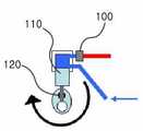
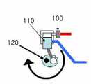
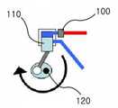
도 2a 내지 도 2d는 종래의 3상 브러쉬리스 직류 모터의 회전에 따른 피스톤 및 실린더의 동작 상태를 나타낸 개략도이다.2A to 2D are schematic diagrams showing an operating state of a piston and a cylinder according to the rotation of a conventional three-phase brushless DC motor.
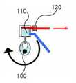
도 2a 내지 도 2d를 참조하면, 회전축(120)이 브러쉬리스 직류 모터와 함께 회전하면 회전운동을 피스톤(110)의 왕복운동으로 바꾸어 냉매를 흡입, 압축, 토출시킨다. 피스톤(110)이 도 2b에 도시된 위치에 있는 경우에는 저온, 저압의 냉매가 흡입되고, 피스톤(110)이 도 2c의 위치에 있는 경우에는 피스톤에 의해 유입된 냉매가 압축되면서 고온, 고압이 된다. 피스톤(110)이 도 2d의 위치에 있는 경우에는 밸브(100)가 개방되어 고온, 고압의 냉매가 토출된다.2A to 2D, when the rotating
피스톤이 가장 위 또는 아래에 위치하는 경우, 즉 도 2b 또는 도 2d에 도시된 위치에 있는 경우에는 초기 구동시 에너지 소모가 크고, 피스톤이 실리더의 중간에 위치할 때(도 2a 또는 도 2c)는 있을 때는 초기 구동시 에너지 소모가 가장 작다. 상기 두 경우에는 초기 구동시 필요로 하는 에너지 차이가 크지는 않지만, 초기 구동시 소비전력이 작은 경우에 맞는 입력파형이 인가되므로 회전자가 다른 위치에 있을 경우에는 순간적으로 많은 전력을 인가하여 도 2a 또는 도 2c의 상태로 강제정렬시켜야 한다. 따라서, 큰 소음과 많은 전력 소모가 발생한다.When the piston is located at the top or bottom, i.e. in the position shown in Fig. 2b or 2d, the energy consumption is high during the initial driving, and when the piston is located in the middle of the cylinder (Fig. 2a or Fig. 2c) When is used, energy consumption is the smallest at the initial operation. In the above two cases, the energy difference required for the initial driving is not large. However, since the input waveform is applied when the power consumption is small during the initial driving, when the rotor is in another position, a large amount of power is instantaneously applied to FIG. 2A or FIG. It must be forced to the state of FIG. 2C. Therefore, loud noise and a lot of power consumption occur.
도 3은 종래 기술에 따른 직류 모터의 회전자의 위치에 따른 3상 파형을 도시한 회로도이다.3 is a circuit diagram showing a three-phase waveform according to the position of the rotor of the DC motor according to the prior art.
도 3을 참조하면, 6개의 스위치(U+, V+, W+, U-, V-, W-)의 스위칭 동작에 의해 모터에 인가되는 파형이 변화한다.Referring to FIG. 3, the waveform applied to the motor is changed by the switching operations of the six switches U +, V +, W +, U-, V-, and W-.
도 4는 종래 기술에 따른 직류 모터에 인가되는 PWM 파형을 도시한 파형도이다.4 is a waveform diagram illustrating a PWM waveform applied to a DC motor according to the prior art.
도 4를 참조하면, U+, V+, W+, U-, V- 및 W-에 인가되는 신호는 IPM을 통하여 모터에 입력되는데, V-와 W+에 인가되는 입력 전압(강제 정렬 신호)으로 모터가 초기 구동 되며 상기 입력 전압에 의해 회전축은 강제로 도 2a 또는 도 2c도 도시된 위치에 있게 된다. 만약, 초기 구동 전에 회전축이 도 2b 또는 도 2d의 위치에 있게 되면, 초기 구동시 많은 전류소모가 발생하며, 큰 소음이 발생할 수 있을 뿐만 아니라 모터는 회전에 실패하기도 한다. 회전자의 정렬이 완료되면, 위치감지 없이 강제로 기동하여(강제 기동 구간) 위치를 검출할 수 있는 속도까지 끌어올린다. 그 다음에 위치를 검출하며 적절한 파형을 입력하여 모터를 구동한다(구동 구간).Referring to FIG. 4, signals applied to U +, V +, W +, U-, V-, and W- are input to the motor through IPM, and the motor is driven by input voltages (forced alignment signals) applied to V- and W +. Initially driven and by the input voltage the axis of rotation is forcibly in the position shown in Fig. 2a or 2c. If the axis of rotation is in the position of Fig. 2b or 2d before the initial driving, a lot of current consumption occurs during the initial driving, not only may a loud noise occur, but also the motor may fail to rotate. When the alignment of the rotor is completed, it is forcibly started without the position detection (forced start section) and raised to the speed at which the position can be detected. Then the position is detected and the appropriate waveform is input to drive the motor (drive section).
회전시 가장 압력이 높은 경우는 도 2c에서 도 2d의 상태로 피스톤이 이동하는 경우이다. 실제로 콤프레서가 회전하다가 정지하면 로터는 대부분 도 2b의 상태에 위치한다. 피스톤이 올라갈 때 압력이 높아 올라가지 못하고 아래쪽에 머물게 된다. 정지시에는 도 2b 상태에 로터가 정지해 있기 때문에 정렬은 도 1b 근처에서 하고(정렬시 소음감소), 강제기동으로 피스톤을 밀고 올라가는 것이 가장 이상적이다. 그러나, 이러한 방법으로 콤프레서를 재기동하는 경우라도 따라 기동이 실패할 수가 있다는 문제점이 있다.The highest pressure during rotation is when the piston moves from the state of FIG. 2C to FIG. 2D. In fact, when the compressor rotates and stops, the rotor is mostly in the state of FIG. 2B. When the piston rises, the pressure does not rise and stays below. Since the rotor is stationary in the state of FIG. 2B at the time of stop, alignment is ideal near FIG. 1B (noise at the time of alignment), and it is most ideal to push the piston up by forced operation. However, there is a problem in that starting may fail even if the compressor is restarted in this manner.
상술한 문제점을 해결하기 위하여 피스톤과 모터 회전자의 관성을 이용하여 재기동 실패를 방지할 수 있는 컴프레서의 직류 모터 구동 방법을 제공하는 것을 그 목적으로 한다.In order to solve the above problems, it is an object of the present invention to provide a DC motor driving method of a compressor that can prevent the restart failure by using the inertia of the piston and the motor rotor.
본 발명에 따른 컴프레서의 직류 모터를 구동하는 방법은 컴프레서의 직류 모터의 회전력을 이용하여 냉매를 흡입, 압축 및 토출하는 과정을 반복하는 컴프레서의 직류 모터를 구동하는 방법에 있어서, (a) 직류 모터의 작동을 정지하고 상기 냉매가 흡입된 상태로 피스톤을 정지하는 단계; (b) 상기 직류 모터를 역방향으로 회전시켜 상기 냉매를 토출시키고 상기 역방향 회전에 따라 움직인 상기 피스톤을 정지하는 단계; 및 (c) 상기 직류 모터를 정방향으로 회전시켜 상기 컴프레서를 재기동하는 단계를 포함하는 것을 특징으로 한다.A method of driving a DC motor of a compressor according to the present invention is a method of driving a DC motor of a compressor which repeats a process of sucking, compressing and discharging a refrigerant using the rotational force of the DC motor of the compressor. Stopping the operation of the piston and stopping the piston with the refrigerant sucked; (b) rotating the DC motor in a reverse direction to discharge the refrigerant and to stop the piston moving according to the reverse rotation; And (c) rotating the DC motor in the forward direction to restart the compressor.
상기 직류모터는 상기 (b) 단계에서 정지한 위치로부터 상기 (c) 단계의 재기동 위치까지 360˚ 회전한다.The DC motor rotates 360 ° from the position stopped in the step (b) to the restart position in the step (c).
이하에서는, 본 발명에 따른 바람직한 실시예를 첨부된 도면을 참조하여 상세히 설명한다.Hereinafter, with reference to the accompanying drawings a preferred embodiment according to the present invention will be described in detail.
도 5a 내지 도 5i는 본 발명에 따른 컴프레서의 직류 모터 구동 방법을 도시한 도면이다.5A to 5I are views illustrating a DC motor driving method of the compressor according to the present invention.
먼저, 도 5a 내지 도 5d에 도시된 바와 같이, 직류 모터의 회전력은 피스톤의 왕복 운동으로 변환되어 냉매의 흡입과 압축 및 토출이 반복된다.First, as shown in FIGS. 5A to 5D, the rotational force of the DC motor is converted into the reciprocating motion of the piston so that the suction, compression and discharge of the refrigerant are repeated.
직류 모터의 회전에 따라 도 5e와 같이 피스톤은 하강하고 직류 모터의 작동이 정지되면 피스톤은 도 5f의 위치에 정지하게 된다. 도 5f의 위치에 정지하는 이유는 도 5f의 위치가 정지시 소음이 가장 적기 때문이다.As the DC motor rotates, as shown in FIG. 5E, when the piston descends and the operation of the DC motor stops, the piston stops at the position of FIG. 5F. The reason for stopping in the position of FIG. 5F is because the noise in the position of FIG. 5F is the least.
도 5f의 위치에 정지한 후 재기동시 직류 모터는 역방향으로 회전하여 도 5g의 위치를 거쳐 도 5h의 위치에 정지하게 된다. 이때 냉매는 토출된다.When the motor is restarted after stopping at the position of FIG. 5F, the DC motor rotates in the reverse direction to stop at the position of FIG. 5H via the position of FIG. 5G. At this time, the refrigerant is discharged.
도 5h의 위치에 정지한 후 직류 모터는 도 5i에 도시된 바와 같이 다시 순방향으로 회전을 시작하고 컴프레서가 재기동된다.After stopping at the position of FIG. 5H, the DC motor starts to rotate in the forward direction again as shown in FIG. 5I and the compressor is restarted.
상기 도 5h의 위치로부터 실제로 컴프레서가 재기동되는 위치에 도달하면 직류 모터는 적어도 360˚ 회전한 상태가 되어 관성력의 의해 실패없이 재기동이 가능하다.When the compressor reaches the position where the compressor is actually restarted from the position of FIG. 5H, the DC motor is rotated by at least 360 ° and can be restarted without failure by the inertia force.
즉, 초기 기동이 성공하기 위해서는 첫회전시 큰 에너지가 필요하며 로터 회전속도도 빨라야한다. 따라서, 모터 회전방향과 반대(역방향)로 강제로 피스톤을 끌어올린후 강제기동을 시작하면 관성에 의해 안정적으로 피스톤을 밀어올릴 수 있다.In other words, in order for the initial start to succeed, a large amount of energy is required at the first rotation and the rotor rotation speed must be high. Therefore, when the piston is forcibly pulled up in the opposite direction to the motor rotation direction (reverse direction) and the forced start is started, the piston can be stably pushed up by inertia.
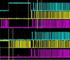
도 6은 본 발명에 따른 컴프레서의 직류 모터 구동 파형을 도시한 파형도이 다.6 is a waveform diagram showing a DC motor driving waveform of the compressor according to the present invention.
도 6을 참조하면, 강제 정렬 구간에서 역방향 회전이 발생하고 역회전 후 재기동이 시작되어 안정적인 재기동이 가능하다.Referring to FIG. 6, a reverse rotation occurs in the forced alignment section, and restarting is started after the reverse rotation, thereby enabling stable restart.
본 발명은 컴프레서의 직류 모터 구동 방법에 관한 것으로, 특히 모터를 역회전시켜 피스톤과 모터 회전자의 관성을 발생시킴으로써 재기동 실패를 방지하고 안정적인 재기동이 가능하다는 장점이 있다.The present invention relates to a method of driving a DC motor of a compressor, and in particular, by inverting the motor to generate an inertia of the piston and the motor rotor, thereby preventing the restart failure and enabling a stable restart.
Claims (2)
Translated fromKoreanPriority Applications (1)
| Application Number | Priority Date | Filing Date | Title |
|---|---|---|---|
| KR1020060100203AKR100779192B1 (en) | 2006-10-16 | 2006-10-16 | DC motor drive method of compressor |
Applications Claiming Priority (1)
| Application Number | Priority Date | Filing Date | Title |
|---|---|---|---|
| KR1020060100203AKR100779192B1 (en) | 2006-10-16 | 2006-10-16 | DC motor drive method of compressor |
Publications (1)
| Publication Number | Publication Date |
|---|---|
| KR100779192B1true KR100779192B1 (en) | 2007-11-23 |
Family
ID=39080743
Family Applications (1)
| Application Number | Title | Priority Date | Filing Date |
|---|---|---|---|
| KR1020060100203AExpired - Fee RelatedKR100779192B1 (en) | 2006-10-16 | 2006-10-16 | DC motor drive method of compressor |
Country Status (1)
| Country | Link |
|---|---|
| KR (1) | KR100779192B1 (en) |
Cited By (4)
| Publication number | Priority date | Publication date | Assignee | Title |
|---|---|---|---|---|
| US20130280095A1 (en)* | 2012-04-20 | 2013-10-24 | General Electric Company | Method and system for reciprocating compressor starting |
| US9897082B2 (en) | 2011-09-15 | 2018-02-20 | General Electric Company | Air compressor prognostic system |
| US10338580B2 (en) | 2014-10-22 | 2019-07-02 | Ge Global Sourcing Llc | System and method for determining vehicle orientation in a vehicle consist |
| US10464579B2 (en) | 2006-04-17 | 2019-11-05 | Ge Global Sourcing Llc | System and method for automated establishment of a vehicle consist |
Citations (3)
| Publication number | Priority date | Publication date | Assignee | Title |
|---|---|---|---|---|
| KR960023790A (en)* | 1994-12-02 | 1996-07-20 | 김광호 | Apparatus and method for starting circuit protection of a DC brushless motor compressor |
| KR970021731A (en)* | 1995-10-25 | 1997-05-28 | 전성원 | Electric Air Conditioning Compressor for Car |
| KR20030096251A (en)* | 2001-03-30 | 2003-12-24 | 요크 인터내셔날 코포레이션 | Variable capacity compressor having adjustable crankpin throw structure |
- 2006
- 2006-10-16KRKR1020060100203Apatent/KR100779192B1/ennot_activeExpired - Fee Related
Patent Citations (3)
| Publication number | Priority date | Publication date | Assignee | Title |
|---|---|---|---|---|
| KR960023790A (en)* | 1994-12-02 | 1996-07-20 | 김광호 | Apparatus and method for starting circuit protection of a DC brushless motor compressor |
| KR970021731A (en)* | 1995-10-25 | 1997-05-28 | 전성원 | Electric Air Conditioning Compressor for Car |
| KR20030096251A (en)* | 2001-03-30 | 2003-12-24 | 요크 인터내셔날 코포레이션 | Variable capacity compressor having adjustable crankpin throw structure |
Cited By (7)
| Publication number | Priority date | Publication date | Assignee | Title |
|---|---|---|---|---|
| US10464579B2 (en) | 2006-04-17 | 2019-11-05 | Ge Global Sourcing Llc | System and method for automated establishment of a vehicle consist |
| US9897082B2 (en) | 2011-09-15 | 2018-02-20 | General Electric Company | Air compressor prognostic system |
| US20130280095A1 (en)* | 2012-04-20 | 2013-10-24 | General Electric Company | Method and system for reciprocating compressor starting |
| US9677556B2 (en) | 2012-04-20 | 2017-06-13 | General Electric Company | System and method for a compressor |
| US9771933B2 (en) | 2012-04-20 | 2017-09-26 | General Electric Company | System and method for a compressor |
| US10233920B2 (en) | 2012-04-20 | 2019-03-19 | Ge Global Sourcing Llc | System and method for a compressor |
| US10338580B2 (en) | 2014-10-22 | 2019-07-02 | Ge Global Sourcing Llc | System and method for determining vehicle orientation in a vehicle consist |
Similar Documents
| Publication | Publication Date | Title |
|---|---|---|
| CN100435471C (en) | Refrigerator Controls | |
| JP4077868B2 (en) | Heat pump application equipment using an expander | |
| CN1948755B (en) | Compressor and driving method thereof | |
| JP4075338B2 (en) | Control method of electric compressor | |
| CN100366902C (en) | Drives for electric compressors | |
| CN103107753B (en) | Compressor start method and apparatus | |
| KR100779192B1 (en) | DC motor drive method of compressor | |
| EP2873865B1 (en) | Motor-driven compressor | |
| JP3672637B2 (en) | Compressor motor control device | |
| WO2005074118A1 (en) | Brushless motor start method, drive device, and refrigerator | |
| JP2008289310A (en) | Motor drive device and refrigerator using the same | |
| JP2015105648A (en) | Electric compressor and its control method | |
| CN111615785B (en) | Electric compressor | |
| WO2007116730A1 (en) | Apparatus and method for controlling reciprocal compressor | |
| JP3776102B2 (en) | Brushless motor control device | |
| JP2016163480A (en) | Compressor motor control device | |
| JP2005214486A (en) | refrigerator | |
| JP2010252480A (en) | Motor drive device and refrigerator using the same | |
| JP5445426B2 (en) | Electric motor control device for electric compressor | |
| JP3812613B2 (en) | Control method of brushless motor | |
| JP3669972B2 (en) | Refrigerator control device | |
| KR20170101054A (en) | Compressor and starting control method for compressor | |
| JP2007295673A (en) | Motor controller | |
| KR20100058203A (en) | Control method of compressor | |
| KR100804958B1 (en) | Compressor motor drive control method for refrigerator |
Legal Events
| Date | Code | Title | Description |
|---|---|---|---|
| A201 | Request for examination | ||
| PA0109 | Patent application | St.27 status event code:A-0-1-A10-A12-nap-PA0109 | |
| PA0201 | Request for examination | St.27 status event code:A-1-2-D10-D11-exm-PA0201 | |
| R17-X000 | Change to representative recorded | St.27 status event code:A-3-3-R10-R17-oth-X000 | |
| E902 | Notification of reason for refusal | ||
| PE0902 | Notice of grounds for rejection | St.27 status event code:A-1-2-D10-D21-exm-PE0902 | |
| P11-X000 | Amendment of application requested | St.27 status event code:A-2-2-P10-P11-nap-X000 | |
| P13-X000 | Application amended | St.27 status event code:A-2-2-P10-P13-nap-X000 | |
| E701 | Decision to grant or registration of patent right | ||
| PE0701 | Decision of registration | St.27 status event code:A-1-2-D10-D22-exm-PE0701 | |
| GRNT | Written decision to grant | ||
| PR0701 | Registration of establishment | St.27 status event code:A-2-4-F10-F11-exm-PR0701 | |
| PR1002 | Payment of registration fee | St.27 status event code:A-2-2-U10-U11-oth-PR1002 Fee payment year number:1 | |
| PG1601 | Publication of registration | St.27 status event code:A-4-4-Q10-Q13-nap-PG1601 | |
| R18-X000 | Changes to party contact information recorded | St.27 status event code:A-5-5-R10-R18-oth-X000 | |
| PN2301 | Change of applicant | St.27 status event code:A-5-5-R10-R11-asn-PN2301 | |
| PN2301 | Change of applicant | St.27 status event code:A-5-5-R10-R11-asn-PN2301 | |
| PN2301 | Change of applicant | St.27 status event code:A-5-5-R10-R14-asn-PN2301 | |
| PR1001 | Payment of annual fee | St.27 status event code:A-4-4-U10-U11-oth-PR1001 Fee payment year number:4 | |
| PR1001 | Payment of annual fee | St.27 status event code:A-4-4-U10-U11-oth-PR1001 Fee payment year number:5 | |
| FPAY | Annual fee payment | Payment date:20121116 Year of fee payment:6 | |
| PR1001 | Payment of annual fee | St.27 status event code:A-4-4-U10-U11-oth-PR1001 Fee payment year number:6 | |
| PN2301 | Change of applicant | St.27 status event code:A-5-5-R10-R13-asn-PN2301 St.27 status event code:A-5-5-R10-R11-asn-PN2301 | |
| FPAY | Annual fee payment | Payment date:20131114 Year of fee payment:7 | |
| PR1001 | Payment of annual fee | St.27 status event code:A-4-4-U10-U11-oth-PR1001 Fee payment year number:7 | |
| R18-X000 | Changes to party contact information recorded | St.27 status event code:A-5-5-R10-R18-oth-X000 | |
| FPAY | Annual fee payment | Payment date:20141111 Year of fee payment:8 | |
| PR1001 | Payment of annual fee | St.27 status event code:A-4-4-U10-U11-oth-PR1001 Fee payment year number:8 | |
| FPAY | Annual fee payment | Payment date:20151110 Year of fee payment:9 | |
| PR1001 | Payment of annual fee | St.27 status event code:A-4-4-U10-U11-oth-PR1001 Fee payment year number:9 | |
| P22-X000 | Classification modified | St.27 status event code:A-4-4-P10-P22-nap-X000 | |
| FPAY | Annual fee payment | Payment date:20161111 Year of fee payment:10 | |
| PR1001 | Payment of annual fee | St.27 status event code:A-4-4-U10-U11-oth-PR1001 Fee payment year number:10 | |
| FPAY | Annual fee payment | Payment date:20171102 Year of fee payment:11 | |
| PR1001 | Payment of annual fee | St.27 status event code:A-4-4-U10-U11-oth-PR1001 Fee payment year number:11 | |
| R18-X000 | Changes to party contact information recorded | St.27 status event code:A-5-5-R10-R18-oth-X000 | |
| LAPS | Lapse due to unpaid annual fee | ||
| PC1903 | Unpaid annual fee | St.27 status event code:A-4-4-U10-U13-oth-PC1903 Not in force date:20181120 Payment event data comment text:Termination Category : DEFAULT_OF_REGISTRATION_FEE | |
| R18-X000 | Changes to party contact information recorded | St.27 status event code:A-5-5-R10-R18-oth-X000 | |
| PN2301 | Change of applicant | St.27 status event code:A-5-5-R10-R13-asn-PN2301 St.27 status event code:A-5-5-R10-R11-asn-PN2301 | |
| PC1903 | Unpaid annual fee | St.27 status event code:N-4-6-H10-H13-oth-PC1903 Ip right cessation event data comment text:Termination Category : DEFAULT_OF_REGISTRATION_FEE Not in force date:20181120 | |
| PN2301 | Change of applicant | St.27 status event code:A-5-5-R10-R13-asn-PN2301 St.27 status event code:A-5-5-R10-R11-asn-PN2301 |