KR100777501B1 - Phosphor composition and method for producing the same, and light-emitting device using the same - Google Patents
Phosphor composition and method for producing the same, and light-emitting device using the sameDownload PDFInfo
- Publication number
- KR100777501B1 KR100777501B1KR1020067024124AKR20067024124AKR100777501B1KR 100777501 B1KR100777501 B1KR 100777501B1KR 1020067024124 AKR1020067024124 AKR 1020067024124AKR 20067024124 AKR20067024124 AKR 20067024124AKR 100777501 B1KR100777501 B1KR 100777501B1
- Authority
- KR
- South Korea
- Prior art keywords
- phosphor
- light
- light emitting
- composition
- emitting device
- Prior art date
- Legal status (The legal status is an assumption and is not a legal conclusion. Google has not performed a legal analysis and makes no representation as to the accuracy of the status listed.)
- Expired - Lifetime
Links
Images


Classifications
- C—CHEMISTRY; METALLURGY
- C09—DYES; PAINTS; POLISHES; NATURAL RESINS; ADHESIVES; COMPOSITIONS NOT OTHERWISE PROVIDED FOR; APPLICATIONS OF MATERIALS NOT OTHERWISE PROVIDED FOR
- C09K—MATERIALS FOR MISCELLANEOUS APPLICATIONS, NOT PROVIDED FOR ELSEWHERE
- C09K11/00—Luminescent, e.g. electroluminescent, chemiluminescent materials
- C09K11/08—Luminescent, e.g. electroluminescent, chemiluminescent materials containing inorganic luminescent materials
- C09K11/77—Luminescent, e.g. electroluminescent, chemiluminescent materials containing inorganic luminescent materials containing rare earth metals
- C09K11/7728—Luminescent, e.g. electroluminescent, chemiluminescent materials containing inorganic luminescent materials containing rare earth metals containing europium
- C—CHEMISTRY; METALLURGY
- C09—DYES; PAINTS; POLISHES; NATURAL RESINS; ADHESIVES; COMPOSITIONS NOT OTHERWISE PROVIDED FOR; APPLICATIONS OF MATERIALS NOT OTHERWISE PROVIDED FOR
- C09K—MATERIALS FOR MISCELLANEOUS APPLICATIONS, NOT PROVIDED FOR ELSEWHERE
- C09K11/00—Luminescent, e.g. electroluminescent, chemiluminescent materials
- C09K11/08—Luminescent, e.g. electroluminescent, chemiluminescent materials containing inorganic luminescent materials
- C09K11/55—Luminescent, e.g. electroluminescent, chemiluminescent materials containing inorganic luminescent materials containing beryllium, magnesium, alkali metals or alkaline earth metals
- C—CHEMISTRY; METALLURGY
- C04—CEMENTS; CONCRETE; ARTIFICIAL STONE; CERAMICS; REFRACTORIES
- C04B—LIME, MAGNESIA; SLAG; CEMENTS; COMPOSITIONS THEREOF, e.g. MORTARS, CONCRETE OR LIKE BUILDING MATERIALS; ARTIFICIAL STONE; CERAMICS; REFRACTORIES; TREATMENT OF NATURAL STONE
- C04B35/00—Shaped ceramic products characterised by their composition; Ceramics compositions; Processing powders of inorganic compounds preparatory to the manufacturing of ceramic products
- C04B35/515—Shaped ceramic products characterised by their composition; Ceramics compositions; Processing powders of inorganic compounds preparatory to the manufacturing of ceramic products based on non-oxide ceramics
- C04B35/58—Shaped ceramic products characterised by their composition; Ceramics compositions; Processing powders of inorganic compounds preparatory to the manufacturing of ceramic products based on non-oxide ceramics based on borides, nitrides, i.e. nitrides, oxynitrides, carbonitrides or oxycarbonitrides or silicides
- C04B35/581—Shaped ceramic products characterised by their composition; Ceramics compositions; Processing powders of inorganic compounds preparatory to the manufacturing of ceramic products based on non-oxide ceramics based on borides, nitrides, i.e. nitrides, oxynitrides, carbonitrides or oxycarbonitrides or silicides based on aluminium nitride
- C—CHEMISTRY; METALLURGY
- C04—CEMENTS; CONCRETE; ARTIFICIAL STONE; CERAMICS; REFRACTORIES
- C04B—LIME, MAGNESIA; SLAG; CEMENTS; COMPOSITIONS THEREOF, e.g. MORTARS, CONCRETE OR LIKE BUILDING MATERIALS; ARTIFICIAL STONE; CERAMICS; REFRACTORIES; TREATMENT OF NATURAL STONE
- C04B35/00—Shaped ceramic products characterised by their composition; Ceramics compositions; Processing powders of inorganic compounds preparatory to the manufacturing of ceramic products
- C04B35/515—Shaped ceramic products characterised by their composition; Ceramics compositions; Processing powders of inorganic compounds preparatory to the manufacturing of ceramic products based on non-oxide ceramics
- C04B35/58—Shaped ceramic products characterised by their composition; Ceramics compositions; Processing powders of inorganic compounds preparatory to the manufacturing of ceramic products based on non-oxide ceramics based on borides, nitrides, i.e. nitrides, oxynitrides, carbonitrides or oxycarbonitrides or silicides
- C04B35/584—Shaped ceramic products characterised by their composition; Ceramics compositions; Processing powders of inorganic compounds preparatory to the manufacturing of ceramic products based on non-oxide ceramics based on borides, nitrides, i.e. nitrides, oxynitrides, carbonitrides or oxycarbonitrides or silicides based on silicon nitride
- C—CHEMISTRY; METALLURGY
- C04—CEMENTS; CONCRETE; ARTIFICIAL STONE; CERAMICS; REFRACTORIES
- C04B—LIME, MAGNESIA; SLAG; CEMENTS; COMPOSITIONS THEREOF, e.g. MORTARS, CONCRETE OR LIKE BUILDING MATERIALS; ARTIFICIAL STONE; CERAMICS; REFRACTORIES; TREATMENT OF NATURAL STONE
- C04B35/00—Shaped ceramic products characterised by their composition; Ceramics compositions; Processing powders of inorganic compounds preparatory to the manufacturing of ceramic products
- C04B35/622—Forming processes; Processing powders of inorganic compounds preparatory to the manufacturing of ceramic products
- C04B35/626—Preparing or treating the powders individually or as batches ; preparing or treating macroscopic reinforcing agents for ceramic products, e.g. fibres; mechanical aspects section B
- C04B35/62605—Treating the starting powders individually or as mixtures
- C04B35/62645—Thermal treatment of powders or mixtures thereof other than sintering
- C04B35/6265—Thermal treatment of powders or mixtures thereof other than sintering involving reduction or oxidation
- C—CHEMISTRY; METALLURGY
- C04—CEMENTS; CONCRETE; ARTIFICIAL STONE; CERAMICS; REFRACTORIES
- C04B—LIME, MAGNESIA; SLAG; CEMENTS; COMPOSITIONS THEREOF, e.g. MORTARS, CONCRETE OR LIKE BUILDING MATERIALS; ARTIFICIAL STONE; CERAMICS; REFRACTORIES; TREATMENT OF NATURAL STONE
- C04B35/00—Shaped ceramic products characterised by their composition; Ceramics compositions; Processing powders of inorganic compounds preparatory to the manufacturing of ceramic products
- C04B35/622—Forming processes; Processing powders of inorganic compounds preparatory to the manufacturing of ceramic products
- C04B35/626—Preparing or treating the powders individually or as batches ; preparing or treating macroscopic reinforcing agents for ceramic products, e.g. fibres; mechanical aspects section B
- C04B35/62605—Treating the starting powders individually or as mixtures
- C04B35/62645—Thermal treatment of powders or mixtures thereof other than sintering
- C04B35/6268—Thermal treatment of powders or mixtures thereof other than sintering characterised by the applied pressure or type of atmosphere, e.g. in vacuum, hydrogen or a specific oxygen pressure
- C—CHEMISTRY; METALLURGY
- C09—DYES; PAINTS; POLISHES; NATURAL RESINS; ADHESIVES; COMPOSITIONS NOT OTHERWISE PROVIDED FOR; APPLICATIONS OF MATERIALS NOT OTHERWISE PROVIDED FOR
- C09K—MATERIALS FOR MISCELLANEOUS APPLICATIONS, NOT PROVIDED FOR ELSEWHERE
- C09K11/00—Luminescent, e.g. electroluminescent, chemiluminescent materials
- C09K11/08—Luminescent, e.g. electroluminescent, chemiluminescent materials containing inorganic luminescent materials
- C09K11/59—Luminescent, e.g. electroluminescent, chemiluminescent materials containing inorganic luminescent materials containing silicon
- C—CHEMISTRY; METALLURGY
- C09—DYES; PAINTS; POLISHES; NATURAL RESINS; ADHESIVES; COMPOSITIONS NOT OTHERWISE PROVIDED FOR; APPLICATIONS OF MATERIALS NOT OTHERWISE PROVIDED FOR
- C09K—MATERIALS FOR MISCELLANEOUS APPLICATIONS, NOT PROVIDED FOR ELSEWHERE
- C09K11/00—Luminescent, e.g. electroluminescent, chemiluminescent materials
- C09K11/08—Luminescent, e.g. electroluminescent, chemiluminescent materials containing inorganic luminescent materials
- C09K11/65—Luminescent, e.g. electroluminescent, chemiluminescent materials containing inorganic luminescent materials containing carbon
- C—CHEMISTRY; METALLURGY
- C09—DYES; PAINTS; POLISHES; NATURAL RESINS; ADHESIVES; COMPOSITIONS NOT OTHERWISE PROVIDED FOR; APPLICATIONS OF MATERIALS NOT OTHERWISE PROVIDED FOR
- C09K—MATERIALS FOR MISCELLANEOUS APPLICATIONS, NOT PROVIDED FOR ELSEWHERE
- C09K11/00—Luminescent, e.g. electroluminescent, chemiluminescent materials
- C09K11/08—Luminescent, e.g. electroluminescent, chemiluminescent materials containing inorganic luminescent materials
- C09K11/77—Luminescent, e.g. electroluminescent, chemiluminescent materials containing inorganic luminescent materials containing rare earth metals
- C09K11/7715—Luminescent, e.g. electroluminescent, chemiluminescent materials containing inorganic luminescent materials containing rare earth metals containing cerium
- C09K11/77218—Silicon Aluminium Nitrides or Silicon Aluminium Oxynitrides
- C—CHEMISTRY; METALLURGY
- C09—DYES; PAINTS; POLISHES; NATURAL RESINS; ADHESIVES; COMPOSITIONS NOT OTHERWISE PROVIDED FOR; APPLICATIONS OF MATERIALS NOT OTHERWISE PROVIDED FOR
- C09K—MATERIALS FOR MISCELLANEOUS APPLICATIONS, NOT PROVIDED FOR ELSEWHERE
- C09K11/00—Luminescent, e.g. electroluminescent, chemiluminescent materials
- C09K11/08—Luminescent, e.g. electroluminescent, chemiluminescent materials containing inorganic luminescent materials
- C09K11/77—Luminescent, e.g. electroluminescent, chemiluminescent materials containing inorganic luminescent materials containing rare earth metals
- C09K11/7728—Luminescent, e.g. electroluminescent, chemiluminescent materials containing inorganic luminescent materials containing rare earth metals containing europium
- C09K11/7729—Chalcogenides
- C—CHEMISTRY; METALLURGY
- C09—DYES; PAINTS; POLISHES; NATURAL RESINS; ADHESIVES; COMPOSITIONS NOT OTHERWISE PROVIDED FOR; APPLICATIONS OF MATERIALS NOT OTHERWISE PROVIDED FOR
- C09K—MATERIALS FOR MISCELLANEOUS APPLICATIONS, NOT PROVIDED FOR ELSEWHERE
- C09K11/00—Luminescent, e.g. electroluminescent, chemiluminescent materials
- C09K11/08—Luminescent, e.g. electroluminescent, chemiluminescent materials containing inorganic luminescent materials
- C09K11/77—Luminescent, e.g. electroluminescent, chemiluminescent materials containing inorganic luminescent materials containing rare earth metals
- C09K11/7728—Luminescent, e.g. electroluminescent, chemiluminescent materials containing inorganic luminescent materials containing rare earth metals containing europium
- C09K11/77342—Silicates
- C—CHEMISTRY; METALLURGY
- C09—DYES; PAINTS; POLISHES; NATURAL RESINS; ADHESIVES; COMPOSITIONS NOT OTHERWISE PROVIDED FOR; APPLICATIONS OF MATERIALS NOT OTHERWISE PROVIDED FOR
- C09K—MATERIALS FOR MISCELLANEOUS APPLICATIONS, NOT PROVIDED FOR ELSEWHERE
- C09K11/00—Luminescent, e.g. electroluminescent, chemiluminescent materials
- C09K11/08—Luminescent, e.g. electroluminescent, chemiluminescent materials containing inorganic luminescent materials
- C09K11/77—Luminescent, e.g. electroluminescent, chemiluminescent materials containing inorganic luminescent materials containing rare earth metals
- C09K11/7728—Luminescent, e.g. electroluminescent, chemiluminescent materials containing inorganic luminescent materials containing rare earth metals containing europium
- C09K11/77348—Silicon Aluminium Nitrides or Silicon Aluminium Oxynitrides
- H—ELECTRICITY
- H05—ELECTRIC TECHNIQUES NOT OTHERWISE PROVIDED FOR
- H05B—ELECTRIC HEATING; ELECTRIC LIGHT SOURCES NOT OTHERWISE PROVIDED FOR; CIRCUIT ARRANGEMENTS FOR ELECTRIC LIGHT SOURCES, IN GENERAL
- H05B33/00—Electroluminescent light sources
- H05B33/12—Light sources with substantially two-dimensional radiating surfaces
- H—ELECTRICITY
- H10—SEMICONDUCTOR DEVICES; ELECTRIC SOLID-STATE DEVICES NOT OTHERWISE PROVIDED FOR
- H10H—INORGANIC LIGHT-EMITTING SEMICONDUCTOR DEVICES HAVING POTENTIAL BARRIERS
- H10H20/00—Individual inorganic light-emitting semiconductor devices having potential barriers, e.g. light-emitting diodes [LED]
- H10H20/80—Constructional details
- H10H20/85—Packages
- H10H20/851—Wavelength conversion means
- H10H20/8511—Wavelength conversion means characterised by their material, e.g. binder
- H10H20/8512—Wavelength conversion materials
- C—CHEMISTRY; METALLURGY
- C04—CEMENTS; CONCRETE; ARTIFICIAL STONE; CERAMICS; REFRACTORIES
- C04B—LIME, MAGNESIA; SLAG; CEMENTS; COMPOSITIONS THEREOF, e.g. MORTARS, CONCRETE OR LIKE BUILDING MATERIALS; ARTIFICIAL STONE; CERAMICS; REFRACTORIES; TREATMENT OF NATURAL STONE
- C04B2235/00—Aspects relating to ceramic starting mixtures or sintered ceramic products
- C04B2235/02—Composition of constituents of the starting material or of secondary phases of the final product
- C04B2235/30—Constituents and secondary phases not being of a fibrous nature
- C04B2235/32—Metal oxides, mixed metal oxides, or oxide-forming salts thereof, e.g. carbonates, nitrates, (oxy)hydroxides, chlorides
- C04B2235/3205—Alkaline earth oxides or oxide forming salts thereof, e.g. beryllium oxide
- C04B2235/3213—Strontium oxides or oxide-forming salts thereof
- C—CHEMISTRY; METALLURGY
- C04—CEMENTS; CONCRETE; ARTIFICIAL STONE; CERAMICS; REFRACTORIES
- C04B—LIME, MAGNESIA; SLAG; CEMENTS; COMPOSITIONS THEREOF, e.g. MORTARS, CONCRETE OR LIKE BUILDING MATERIALS; ARTIFICIAL STONE; CERAMICS; REFRACTORIES; TREATMENT OF NATURAL STONE
- C04B2235/00—Aspects relating to ceramic starting mixtures or sintered ceramic products
- C04B2235/02—Composition of constituents of the starting material or of secondary phases of the final product
- C04B2235/30—Constituents and secondary phases not being of a fibrous nature
- C04B2235/32—Metal oxides, mixed metal oxides, or oxide-forming salts thereof, e.g. carbonates, nitrates, (oxy)hydroxides, chlorides
- C04B2235/3224—Rare earth oxide or oxide forming salts thereof, e.g. scandium oxide
- C04B2235/3229—Cerium oxides or oxide-forming salts thereof
- C—CHEMISTRY; METALLURGY
- C04—CEMENTS; CONCRETE; ARTIFICIAL STONE; CERAMICS; REFRACTORIES
- C04B—LIME, MAGNESIA; SLAG; CEMENTS; COMPOSITIONS THEREOF, e.g. MORTARS, CONCRETE OR LIKE BUILDING MATERIALS; ARTIFICIAL STONE; CERAMICS; REFRACTORIES; TREATMENT OF NATURAL STONE
- C04B2235/00—Aspects relating to ceramic starting mixtures or sintered ceramic products
- C04B2235/02—Composition of constituents of the starting material or of secondary phases of the final product
- C04B2235/30—Constituents and secondary phases not being of a fibrous nature
- C04B2235/38—Non-oxide ceramic constituents or additives
- C04B2235/3852—Nitrides, e.g. oxynitrides, carbonitrides, oxycarbonitrides, lithium nitride, magnesium nitride
- C04B2235/3865—Aluminium nitrides
- C—CHEMISTRY; METALLURGY
- C04—CEMENTS; CONCRETE; ARTIFICIAL STONE; CERAMICS; REFRACTORIES
- C04B—LIME, MAGNESIA; SLAG; CEMENTS; COMPOSITIONS THEREOF, e.g. MORTARS, CONCRETE OR LIKE BUILDING MATERIALS; ARTIFICIAL STONE; CERAMICS; REFRACTORIES; TREATMENT OF NATURAL STONE
- C04B2235/00—Aspects relating to ceramic starting mixtures or sintered ceramic products
- C04B2235/02—Composition of constituents of the starting material or of secondary phases of the final product
- C04B2235/30—Constituents and secondary phases not being of a fibrous nature
- C04B2235/38—Non-oxide ceramic constituents or additives
- C04B2235/3852—Nitrides, e.g. oxynitrides, carbonitrides, oxycarbonitrides, lithium nitride, magnesium nitride
- C04B2235/3873—Silicon nitrides, e.g. silicon carbonitride, silicon oxynitride
- H—ELECTRICITY
- H01—ELECTRIC ELEMENTS
- H01L—SEMICONDUCTOR DEVICES NOT COVERED BY CLASS H10
- H01L2224/00—Indexing scheme for arrangements for connecting or disconnecting semiconductor or solid-state bodies and methods related thereto as covered by H01L24/00
- H01L2224/01—Means for bonding being attached to, or being formed on, the surface to be connected, e.g. chip-to-package, die-attach, "first-level" interconnects; Manufacturing methods related thereto
- H01L2224/02—Bonding areas; Manufacturing methods related thereto
- H01L2224/04—Structure, shape, material or disposition of the bonding areas prior to the connecting process
- H01L2224/05—Structure, shape, material or disposition of the bonding areas prior to the connecting process of an individual bonding area
- H01L2224/0554—External layer
- H01L2224/0556—Disposition
- H01L2224/05568—Disposition the whole external layer protruding from the surface
- H—ELECTRICITY
- H01—ELECTRIC ELEMENTS
- H01L—SEMICONDUCTOR DEVICES NOT COVERED BY CLASS H10
- H01L2224/00—Indexing scheme for arrangements for connecting or disconnecting semiconductor or solid-state bodies and methods related thereto as covered by H01L24/00
- H01L2224/01—Means for bonding being attached to, or being formed on, the surface to be connected, e.g. chip-to-package, die-attach, "first-level" interconnects; Manufacturing methods related thereto
- H01L2224/02—Bonding areas; Manufacturing methods related thereto
- H01L2224/04—Structure, shape, material or disposition of the bonding areas prior to the connecting process
- H01L2224/05—Structure, shape, material or disposition of the bonding areas prior to the connecting process of an individual bonding area
- H01L2224/0554—External layer
- H01L2224/05573—Single external layer
- H—ELECTRICITY
- H01—ELECTRIC ELEMENTS
- H01L—SEMICONDUCTOR DEVICES NOT COVERED BY CLASS H10
- H01L2224/00—Indexing scheme for arrangements for connecting or disconnecting semiconductor or solid-state bodies and methods related thereto as covered by H01L24/00
- H01L2224/01—Means for bonding being attached to, or being formed on, the surface to be connected, e.g. chip-to-package, die-attach, "first-level" interconnects; Manufacturing methods related thereto
- H01L2224/02—Bonding areas; Manufacturing methods related thereto
- H01L2224/04—Structure, shape, material or disposition of the bonding areas prior to the connecting process
- H01L2224/05—Structure, shape, material or disposition of the bonding areas prior to the connecting process of an individual bonding area
- H01L2224/0554—External layer
- H01L2224/05599—Material
- H01L2224/056—Material with a principal constituent of the material being a metal or a metalloid, e.g. boron [B], silicon [Si], germanium [Ge], arsenic [As], antimony [Sb], tellurium [Te] and polonium [Po], and alloys thereof
- H—ELECTRICITY
- H01—ELECTRIC ELEMENTS
- H01L—SEMICONDUCTOR DEVICES NOT COVERED BY CLASS H10
- H01L2224/00—Indexing scheme for arrangements for connecting or disconnecting semiconductor or solid-state bodies and methods related thereto as covered by H01L24/00
- H01L2224/01—Means for bonding being attached to, or being formed on, the surface to be connected, e.g. chip-to-package, die-attach, "first-level" interconnects; Manufacturing methods related thereto
- H01L2224/10—Bump connectors; Manufacturing methods related thereto
- H01L2224/12—Structure, shape, material or disposition of the bump connectors prior to the connecting process
- H01L2224/13—Structure, shape, material or disposition of the bump connectors prior to the connecting process of an individual bump connector
- H—ELECTRICITY
- H01—ELECTRIC ELEMENTS
- H01L—SEMICONDUCTOR DEVICES NOT COVERED BY CLASS H10
- H01L2224/00—Indexing scheme for arrangements for connecting or disconnecting semiconductor or solid-state bodies and methods related thereto as covered by H01L24/00
- H01L2224/01—Means for bonding being attached to, or being formed on, the surface to be connected, e.g. chip-to-package, die-attach, "first-level" interconnects; Manufacturing methods related thereto
- H01L2224/42—Wire connectors; Manufacturing methods related thereto
- H01L2224/44—Structure, shape, material or disposition of the wire connectors prior to the connecting process
- H01L2224/45—Structure, shape, material or disposition of the wire connectors prior to the connecting process of an individual wire connector
- H01L2224/45001—Core members of the connector
- H01L2224/45099—Material
- H01L2224/451—Material with a principal constituent of the material being a metal or a metalloid, e.g. boron (B), silicon (Si), germanium (Ge), arsenic (As), antimony (Sb), tellurium (Te) and polonium (Po), and alloys thereof
- H01L2224/45138—Material with a principal constituent of the material being a metal or a metalloid, e.g. boron (B), silicon (Si), germanium (Ge), arsenic (As), antimony (Sb), tellurium (Te) and polonium (Po), and alloys thereof the principal constituent melting at a temperature of greater than or equal to 950°C and less than 1550°C
- H01L2224/45144—Gold (Au) as principal constituent
- H—ELECTRICITY
- H01—ELECTRIC ELEMENTS
- H01L—SEMICONDUCTOR DEVICES NOT COVERED BY CLASS H10
- H01L2224/00—Indexing scheme for arrangements for connecting or disconnecting semiconductor or solid-state bodies and methods related thereto as covered by H01L24/00
- H01L2224/01—Means for bonding being attached to, or being formed on, the surface to be connected, e.g. chip-to-package, die-attach, "first-level" interconnects; Manufacturing methods related thereto
- H01L2224/42—Wire connectors; Manufacturing methods related thereto
- H01L2224/47—Structure, shape, material or disposition of the wire connectors after the connecting process
- H01L2224/48—Structure, shape, material or disposition of the wire connectors after the connecting process of an individual wire connector
- H01L2224/4805—Shape
- H01L2224/4809—Loop shape
- H01L2224/48091—Arched
- H—ELECTRICITY
- H01—ELECTRIC ELEMENTS
- H01L—SEMICONDUCTOR DEVICES NOT COVERED BY CLASS H10
- H01L2224/00—Indexing scheme for arrangements for connecting or disconnecting semiconductor or solid-state bodies and methods related thereto as covered by H01L24/00
- H01L2224/01—Means for bonding being attached to, or being formed on, the surface to be connected, e.g. chip-to-package, die-attach, "first-level" interconnects; Manufacturing methods related thereto
- H01L2224/42—Wire connectors; Manufacturing methods related thereto
- H01L2224/47—Structure, shape, material or disposition of the wire connectors after the connecting process
- H01L2224/48—Structure, shape, material or disposition of the wire connectors after the connecting process of an individual wire connector
- H01L2224/481—Disposition
- H01L2224/48151—Connecting between a semiconductor or solid-state body and an item not being a semiconductor or solid-state body, e.g. chip-to-substrate, chip-to-passive
- H01L2224/48221—Connecting between a semiconductor or solid-state body and an item not being a semiconductor or solid-state body, e.g. chip-to-substrate, chip-to-passive the body and the item being stacked
- H01L2224/48245—Connecting between a semiconductor or solid-state body and an item not being a semiconductor or solid-state body, e.g. chip-to-substrate, chip-to-passive the body and the item being stacked the item being metallic
- H01L2224/48247—Connecting between a semiconductor or solid-state body and an item not being a semiconductor or solid-state body, e.g. chip-to-substrate, chip-to-passive the body and the item being stacked the item being metallic connecting the wire to a bond pad of the item
- H—ELECTRICITY
- H01—ELECTRIC ELEMENTS
- H01L—SEMICONDUCTOR DEVICES NOT COVERED BY CLASS H10
- H01L2224/00—Indexing scheme for arrangements for connecting or disconnecting semiconductor or solid-state bodies and methods related thereto as covered by H01L24/00
- H01L2224/01—Means for bonding being attached to, or being formed on, the surface to be connected, e.g. chip-to-package, die-attach, "first-level" interconnects; Manufacturing methods related thereto
- H01L2224/42—Wire connectors; Manufacturing methods related thereto
- H01L2224/47—Structure, shape, material or disposition of the wire connectors after the connecting process
- H01L2224/48—Structure, shape, material or disposition of the wire connectors after the connecting process of an individual wire connector
- H01L2224/481—Disposition
- H01L2224/48151—Connecting between a semiconductor or solid-state body and an item not being a semiconductor or solid-state body, e.g. chip-to-substrate, chip-to-passive
- H01L2224/48221—Connecting between a semiconductor or solid-state body and an item not being a semiconductor or solid-state body, e.g. chip-to-substrate, chip-to-passive the body and the item being stacked
- H01L2224/48245—Connecting between a semiconductor or solid-state body and an item not being a semiconductor or solid-state body, e.g. chip-to-substrate, chip-to-passive the body and the item being stacked the item being metallic
- H01L2224/48257—Connecting between a semiconductor or solid-state body and an item not being a semiconductor or solid-state body, e.g. chip-to-substrate, chip-to-passive the body and the item being stacked the item being metallic connecting the wire to a die pad of the item
- H—ELECTRICITY
- H01—ELECTRIC ELEMENTS
- H01L—SEMICONDUCTOR DEVICES NOT COVERED BY CLASS H10
- H01L2224/00—Indexing scheme for arrangements for connecting or disconnecting semiconductor or solid-state bodies and methods related thereto as covered by H01L24/00
- H01L2224/80—Methods for connecting semiconductor or other solid state bodies using means for bonding being attached to, or being formed on, the surface to be connected
- H01L2224/85—Methods for connecting semiconductor or other solid state bodies using means for bonding being attached to, or being formed on, the surface to be connected using a wire connector
- H01L2224/85909—Post-treatment of the connector or wire bonding area
- H01L2224/8592—Applying permanent coating, e.g. protective coating
- H—ELECTRICITY
- H01—ELECTRIC ELEMENTS
- H01L—SEMICONDUCTOR DEVICES NOT COVERED BY CLASS H10
- H01L2924/00—Indexing scheme for arrangements or methods for connecting or disconnecting semiconductor or solid-state bodies as covered by H01L24/00
- H01L2924/15—Details of package parts other than the semiconductor or other solid state devices to be connected
- H01L2924/181—Encapsulation
- H—ELECTRICITY
- H10—SEMICONDUCTOR DEVICES; ELECTRIC SOLID-STATE DEVICES NOT OTHERWISE PROVIDED FOR
- H10H—INORGANIC LIGHT-EMITTING SEMICONDUCTOR DEVICES HAVING POTENTIAL BARRIERS
- H10H20/00—Individual inorganic light-emitting semiconductor devices having potential barriers, e.g. light-emitting diodes [LED]
- H10H20/80—Constructional details
- H10H20/85—Packages
- H10H20/851—Wavelength conversion means
- H10H20/8511—Wavelength conversion means characterised by their material, e.g. binder
- H10H20/8512—Wavelength conversion materials
- H10H20/8513—Wavelength conversion materials having two or more wavelength conversion materials
- Y—GENERAL TAGGING OF NEW TECHNOLOGICAL DEVELOPMENTS; GENERAL TAGGING OF CROSS-SECTIONAL TECHNOLOGIES SPANNING OVER SEVERAL SECTIONS OF THE IPC; TECHNICAL SUBJECTS COVERED BY FORMER USPC CROSS-REFERENCE ART COLLECTIONS [XRACs] AND DIGESTS
- Y02—TECHNOLOGIES OR APPLICATIONS FOR MITIGATION OR ADAPTATION AGAINST CLIMATE CHANGE
- Y02B—CLIMATE CHANGE MITIGATION TECHNOLOGIES RELATED TO BUILDINGS, e.g. HOUSING, HOUSE APPLIANCES OR RELATED END-USER APPLICATIONS
- Y02B20/00—Energy efficient lighting technologies, e.g. halogen lamps or gas discharge lamps
- Y—GENERAL TAGGING OF NEW TECHNOLOGICAL DEVELOPMENTS; GENERAL TAGGING OF CROSS-SECTIONAL TECHNOLOGIES SPANNING OVER SEVERAL SECTIONS OF THE IPC; TECHNICAL SUBJECTS COVERED BY FORMER USPC CROSS-REFERENCE ART COLLECTIONS [XRACs] AND DIGESTS
- Y10—TECHNICAL SUBJECTS COVERED BY FORMER USPC
- Y10S—TECHNICAL SUBJECTS COVERED BY FORMER USPC CROSS-REFERENCE ART COLLECTIONS [XRACs] AND DIGESTS
- Y10S428/00—Stock material or miscellaneous articles
- Y10S428/917—Electroluminescent
Landscapes
- Chemical & Material Sciences (AREA)
- Engineering & Computer Science (AREA)
- Materials Engineering (AREA)
- Organic Chemistry (AREA)
- Inorganic Chemistry (AREA)
- Ceramic Engineering (AREA)
- Manufacturing & Machinery (AREA)
- Structural Engineering (AREA)
- Physics & Mathematics (AREA)
- Thermal Sciences (AREA)
- Luminescent Compositions (AREA)
Abstract
Translated fromKoreanDescription
Translated fromKorean본 발명은, 예를 들면, 백색 발광 다이오드(이하, 백색 LED라고 한다)를 비롯한 각종 발광 장치 등에 응용 가능한 새로운 형광체 조성물, 특히, 근자외, 자색 또는 청색광으로 여기되어, 오렌지색 또는 적색의 난색계 발광을 발하는 형광체 조성물과 그 제조 방법 및 그 형광체 조성물을 이용한 발광 장치에 관한 것이다.The present invention is, for example, a novel phosphor composition applicable to various light emitting devices including a white light emitting diode (hereinafter referred to as a white LED), in particular, near-ultraviolet, purple or blue light, and excited orange-red light emission The present invention relates to a phosphor composition, a method for producing the same, and a light emitting device using the phosphor composition.
종래부터, 예를 들면 이하의 질화물계의 형광체가 알려져 있다. 이러한 질화물 형광체는, 자외∼근자외∼자색∼청색광으로 여기 가능하고, 580㎚ 이상 660㎚ 미만의 파장 영역에 발광 피크를 갖는 난색계의 가시광을 발하므로, 예를 들면 백색 LED 광원 등의 발광 장치용으로서 적합한 것도 알려져 있다.Conventionally, the following nitride phosphors are known, for example. Such nitride phosphors can be excited by ultraviolet light, near ultraviolet light, violet light, and blue light, and emit light of a warm color system having an emission peak in a wavelength region of 580 nm or more and less than 660 nm. Thus, for example, for a light emitting device such as a white LED light source, It is also known to be suitable as.
(1) M2Si5N8 : Eu2+(일본 특허공표 2003-515665호 공보 참조)(1) M2 Si5 N8 : Eu2+ (See Japanese Patent Publication No. 2003-515665)
(2) MSi7N10 : Eu2+(일본 특허공표 2003-515665호 공보 참조)(2) MSi 7 N 10: Eu 2 + ( see Japanese Patent Application Publication No. 2003-515665)
(3) M2Si5N8 : Ce3+(일본 특허공개 2002-322474호 공보 참조)(3) M2 Si5 N8 : Ce3+ (See Japanese Patent Laid-Open No. 2002-322474)
(4) Ca1.5A13Si9N16 : Ce3+(일본 특허공개 2003-203504호 공보 참조)(4) Ca1.5 A13 Si9 N16 : Ce3+ (see Japanese Patent Application Laid-Open No. 2003-203504)
(5) Ca1.5A13Si9N16 : Eu2+(일본 특허공개 2003-124527호 공보 참조)(5) Ca1.5 A13 Si9 N16 : Eu2+ (see Japanese Patent Application Laid-Open No. 2003-124527)
(6) CaA12Si10N16 : Eu2+(일본 특허공개 2003-124527호 공보 참조)(6) CaA12 Si10 N16 : Eu2+ (see Japanese Patent Application Laid-Open No. 2003-124527)
(7) Sr1.5Al3Si9N16 : Eu2+(일본 특허공개 2003-124527호 공보 참조)(7) Sr1.5 Al3 Si9 N16 : Eu2+ (See Japanese Patent Application Laid-Open No. 2003-124527)
(8) MSi3N5 : Eu2+(일본 특허공개 2003-206481호 공보 참조)(8) MSi3 N5 : Eu2+ (see Japanese Patent Application Laid-Open No. 2003-206481)
(9) M2Si4N7 : Eu2+(일본 특허공개 2003-206481호 공보 참조)(9) M2 Si4 N7 : Eu2+ (see Japanese Patent Application Laid-Open No. 2003-206481)
(10) CaSi6AlON9 : Eu2+(일본 특허공개 2003-206481호 공보 참조)(10) CaSi6 AlON9 : Eu2+ (see Japanese Patent Application Laid-Open No. 2003-206481)
(11) Sr2Si4AlON7 : Eu2+(일본 특허공개 2003-206481호 공보 참조)(11) Sr2 Si4 AlON7 : Eu2+ (See Japanese Patent Application Laid-Open No. 2003-206481)
(12) CaSiN2 : Eu2+(S. S. Lee, S. Lim, S. S. Sun and J. F. Wager, Proceedings of SPIE-the International Society for Optical Engineering, 제3241권, (1997년), p. 75-83 참조.(12) CaSiN 2: Eu 2 + ( see SS Lee, S. Lim, SS Sun and JF Wager, Proceedings of SPIE-the International Society for Optical Engineering, No. 3241, (year), p 75-83 1997..
단, 상기 M은, 적어도 하나의 알칼리 토류금속 원소(Mg, Ca, Sr, Ba) 또는 아연(Zn)을 표시한다.However, M represents at least one alkaline earth metal element (Mg, Ca, Sr, Ba) or zinc (Zn).
이러한 질화물 형광체는, 종래부터 주로, 상기 원소 M의 질화물 또는 금속 과, 규소의 질화물 및/또는 알루미늄의 질화물을 형광체 모체의 원료로서 이용하고, 발광 중심 이온을 형성하는 원소를 포함하는 화합물과 함께, 질화성 가스 분위기 중에서 반응시키는 제조 방법에 의해서 제조했다. 또한, 종래의 발광 장치에서는, 이러한 질화물 형광체를 이용해 발광 장치를 구성했다.Such a nitride phosphor conventionally mainly uses a nitride or a metal of the element M and a nitride of silicon and / or an aluminum nitride as a raw material of a phosphor matrix, together with a compound containing an element which forms luminescent center ions, It produced by the manufacturing method made to react in nitriding gas atmosphere. In the conventional light emitting device, the light emitting device is configured using such a nitride phosphor.
그러나, 상기 발광 장치에 요구되는 요망이 해마다 다양화되는 중에서, 상기한 종래의 질화물 형광체와는 다른 신규 형광체가 요구되고 있다. 특히, 상기 난색계의 발광 성분, 그 중에서도 적색 발광 성분을 많이 갖는 발광 장치의 수요가 많아, 그 개발 요망이 강한 현재, 그에 응용 가능한 형광체 재료가 적은 현상이 있어, 새로운 형광체 재료와 난색계의 발광 성분을 많이 갖는 새로운 발광 장치의 개발이 기대되고 있다.However, while the demands required for the light emitting device are diversified year by year, new phosphors different from the above-mentioned conventional nitride phosphors are required. In particular, there is a great demand for light emitting devices having a lot of light emitting components of the warm color system, and especially red light emitting components, and there is a phenomenon that there is little phosphor material that can be applied to them. The development of a new light emitting device having a lot is expected.
또한, 종래의 질화물 형광체의 제조 방법에서는, 고순도 재료의 입수나 제조가 곤란하고, 또한, 화학적으로 불안정하기 때문에 대기중에서의 취급도 곤란한 알칼리 토류금속의 질화물이나 알칼리 토류금속 등을 형광체의 주원료로서 이용해 제조하기 때문에, 고순도 형광체의 대량 생산이 어렵고, 제조 수율이 내려가, 형광체 가격이 비싸게 되는 과제도 있다.In addition, in the conventional method for producing a nitride phosphor, nitride or alkaline earth metal of alkaline earth metal, which is difficult to obtain or manufacture high-purity materials and difficult to handle in the air because of chemical instability, is used as the main raw material of the phosphor. In order to manufacture, it is difficult to mass-produce high-purity fluorescent substance, and the manufacturing yield falls, and there exists also a subject that a phosphor price becomes expensive.
또한, 종래의 발광 장치에서는, 적용 가능한 형광체 재료의 종류가 부족하므로, 재료 선택의 여지가 적고, 형광체의 공급 메이커가 한정되기 때문에, 결과적으로, 발광 장치가 비싸게 되는 과제도 있다. 또한, 난색계 발광 성분(특히 적색)의 발광 강도가 강하고, 특수 연색평가지수(演色評價指數) R9가 큰 염가의 발광 장치의 종류가 적은 과제도 있다.In addition, in the conventional light emitting device, since there is a shortage of applicable fluorescent material, there is little room for material selection and the supply of the fluorescent material is limited. As a result, there is a problem that the light emitting device becomes expensive. In addition, there is a problem that the light emission intensity of the warm color light emitting component (particularly red) is strong and the kind of inexpensive light emitting device having a large special color rendering index R9 is small.
본 발명은, 이러한 과제를 해결하기 위해서 이루어진 것으로서, 난색계 발광을 발할 수 있는 완전 신규 형광체 조성물, 특히, 적색광을 발하는 형광체 조성물을 제공하는 것을 목적으로 한다. 또한, 본 발명은, 질화물계의 본 발명에 관한 형광체 조성물의 대량 생산에 적합하고, 염가로 제조할 수 있는 형광체 조성물의 제조 방법을 제공하는 것도 목적으로 한다. 또한, 본 발명은, 난색계 발광 성분(특히 적색)의 발광 강도가 강하고, 특수 연색평가지수(演色評價指數) R9가 큰 염가의 발광 장치를 제공하는 것도 목적으로 한다.This invention is made | formed in order to solve such a subject, and an object of this invention is to provide the fully novel fluorescent substance composition which can emit warm color emission, especially the fluorescent composition which emits red light. Moreover, an object of this invention is to provide the manufacturing method of the fluorescent substance composition suitable for mass production of the fluorescent substance composition which concerns on this invention of nitride system, and can be manufactured at low cost. It is also an object of the present invention to provide an inexpensive light emitting device having a strong light emission intensity of a warm color light emitting component (especially red) and having a large special color rendering index R9.
또한, 본 발명에 관한 형광체의 내부 양자 효율 및 외부 양자 효율의 측정 기술에 대해서는, 이미 고정밀도 측정이 가능한 기술이 확립되어 있어, 형광 램프용의 일부 형광체에 대해서는, 특정한 여기 파장의 광 조사 하(254㎚ 자외선 여기 하)에 있어서, 그 내부 양자 효율 및 외부 양자 효율의 절대치가 알려져 있다(예를 들면, 大久保 和明 외, 「조명 학회지」,평성11년, 제83권, 제2호, p.87 참조).Moreover, about the measurement technique of the internal quantum efficiency and the external quantum efficiency of the fluorescent substance which concerns on this invention, the technique which can measure a high precision has already been established, and about the some fluorescent substance for fluorescent lamps, the light irradiation of a specific excitation wavelength ( In 254 nm ultraviolet excitation), the absolute values of the internal quantum efficiency and the external quantum efficiency are known (for example, 大 久保 和 明 et al., "The Journal of Illumination", 11th, Vol. 83, No. 2, p. .87).
본 발명은, aM3N2·bAlN·cSi3N4의 조성식으로 나타내는 조성물을 형광체 모체의 주체로서 포함하는 형광체 조성물로서, 상기 조성식에 있어서, M은, Mg, Ca, Sr, Ba, 및 Zn으로 이루어지는 군에서 선택되는 적어도 1개의 원소이고, a, b, c는, 각각 0.2≤a/(a+b)≤0.95, 0.05≤b/(b+c)≤0.8, 0.4≤c/(c+a)≤0.95를 만족하는 수치인 것을 특징으로 하는 형광체 조성물이다.The present invention provides a phosphor composition comprising a composition represented by the composition formula of aM3 N2 · bAlN · cSi3 N4 as a main body of the phosphor matrix, wherein in the composition formula, M is Mg, Ca, Sr, Ba, and Zn. At least one element selected from the group consisting of a, b, and c are 0.2 ≦ a / (a + b) ≦ 0.95, 0.05 ≦ b / (b + c) ≦ 0.8, and 0.4 ≦ c / (c, respectively. It is a numerical value which satisfy | fills + a) ≤ 0.95, It is a fluorescent substance composition characterized by the above-mentioned.
또한, 본 발명은, 상기 형광체 조성물을 발광원으로서 이용해 구성한 것을 특징으로 하는 발광 장치이다.Moreover, this invention is the light-emitting device characterized by using the said fluorescent substance composition as a light emitting source.
또한, 본 발명은, 상기 형광체 조성물의 제조 방법으로서, 가열에 의해서 Mg, Ca, Sr, Ba, 및 Zn으로 이루어지는 군에서 선택되는 적어도 1개의 원소의 산화물을 생성할 수 있는 화합물과, 규소 화합물과, 알루미늄 화합물과, 발광 중심 이온을 형성하는 원소를 포함하는 화합물과, 탄소를 포함하는 원료를, 질화성 가스 분위기 중에서 반응시키는 것을 특징으로 하는 형광체 조성물의 제조 방법이다.In addition, the present invention provides a method for producing the phosphor composition, a compound capable of producing an oxide of at least one element selected from the group consisting of Mg, Ca, Sr, Ba, and Zn by heating; , A compound containing an aluminum compound, an element forming an emission center ion and a raw material containing carbon are reacted in a nitriding gas atmosphere.
또한, 본 발명은, 질화물 형광체를 포함하는 형광체층과 발광 소자를 구비하고, 상기 발광 소자는, 360㎚이상 500㎚미만의 파장 영역에 발광 피크를 가지고, 상기 질화물 형광체는, 상기 발광 소자가 발하는 광에 의해서 여기되어 발광하고, 상기 질화물 형광체가 발하는 발광 성분을 출력광으로서 적어도 포함하는 발광 장치로서, 상기 질화물 형광체는, Eu2+으로 부활(付活)되고, 또한, 조성식 (M1-xEux)AlSiN3으로 나타내는 형광체이고, 상기 M은, Mg, Ca, Sr, Ba 및 Zn에서 선택되는 적어도 1개의 원소이고, 상기 x는, 식 0.005≤x≤0.3을 만족하는 수치인 것을 특징으로 하는 발광 장치이다.In addition, the present invention comprises a phosphor layer comprising a nitride phosphor and a light emitting element, wherein the light emitting element has a light emission peak in a wavelength region of 360nm or less than 500nm, the nitride phosphor is emitted from the light emitting element A light emitting device that is excited by light and emits light, and includes at least a light emitting component emitted by the nitride phosphor as output light, wherein the nitride phosphor isactivated with Eu2+ and further comprises a composition formula (M1-x Eux ) AlSiN3 A phosphor, wherein M is at least one element selected from Mg, Ca, Sr, Ba, and Zn, wherein x is a numerical value satisfying the formula 0.005≤x≤0.3 It is a light emitting device.
또한, 본 발명은, 형광체를 포함하는 형광체층과 발광 소자를 구비하고, 상기 발광 소자는, 360㎚이상 500㎚미만의 파장 영역에 발광 피크를 가지고, 상기 형광체는, 상기 발광 소자가 발하는 광에 의해서 여기되어 발광하고, 상기 형광체가 발하는 발광 성분을 출력광으로서 적어도 포함하는 발광 장치로서, 상기 형광체는, Eu2+으로 부활되고, 또한, 600㎚이상 660㎚미만의 파장 영역에 발광 피크를 갖는 질화물 형광체 또는 산질화물 형광체와, Eu2+로 부활되고, 또한, 500㎚이상 600㎚미만의 파장 영역에 발광 피크를 갖는 알칼리 토류금속 오르토규산염 형광체를 포함하고, 상기 발광 소자가 발하는 광 여기 하에서, 상기 형광체의 내부 양자 효율이 80%이상인 것을 특징으로 하는 발광 장치이다.In addition, the present invention includes a phosphor layer including a phosphor and a light emitting element, wherein the light emitting element has a light emission peak in a wavelength region of 360 nm or more and less than 500 nm, and the phosphor is applied to light emitted by the light emitting element. Wherein the phosphor is revived with Eu2+ and has an emission peak in a wavelength region of 600 nm or more and less than 660 nm. Under the light excitation emitted by the light emitting device, the nitride phosphor or the oxynitride phosphor, and an alkaline earth metal orthosilicate phosphor which is activated by Eu2+ and has an emission peak in the wavelength region of 500 nm or more and less than 600 nm, An internal quantum efficiency of the phosphor is 80% or more.
도 1은 본 발명의 실시 형태에 있어서의 반도체 발광 장치의 단면도이다.1 is a cross-sectional view of a semiconductor light emitting device in an embodiment of the present invention.
도 2는 본 발명의 실시 형태에 있어서의 반도체 발광 장치의 단면도이다.2 is a cross-sectional view of a semiconductor light emitting device in an embodiment of the present invention.
도 3은 본 발명의 실시 형태에 있어서의 반도체 발광 장치의 단면도이다.3 is a cross-sectional view of a semiconductor light emitting device in an embodiment of the present invention.
도 4는 본 발명의 실시 형태에 있어서의 조명·표시 장치의 구성을 도시한 개략도이다.4 is a schematic view showing the configuration of an illumination display device according to an embodiment of the present invention.
도 5는 본 발명의 실시 형태에 있어서의 조명·표시 장치의 구성을 도시한 개략도이다.5 is a schematic view showing the configuration of an illumination display device according to the embodiment of the present invention.
도 6은 본 발명의 실시 형태에 있어서의 조명 모듈의 사시도이다.6 is a perspective view of the lighting module in the embodiment of the present invention.
도 7은 본 발명의 실시 형태에 있어서의 조명 모듈의 사시도이다.7 is a perspective view of the lighting module according to the embodiment of the present invention.
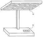
도 8은 본 발명의 실시 형태에 있어서의 조명 장치의 사시도이다.8 is a perspective view of the lighting apparatus according to the embodiment of the present invention.
도 9는 본 발명의 실시 형태에 있어서의 조명 장치의 측면도이다.9 is a side view of the lighting apparatus according to the embodiment of the present invention.
도 10은 도 9의 조명 장치의 저면도이다.10 is a bottom view of the lighting apparatus of FIG. 9.
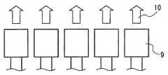
도 11은 본 발명의 실시 형태에 있어서의 화상 표시 장치의 사시도이다.11 is a perspective view of the image display device in the embodiment of the present invention.
도 12는 본 발명의 실시 형태에 있어서의 숫자 표시 장치의 사시도이다.12 is a perspective view of the number display device in the embodiment of the present invention.
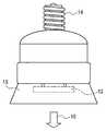
도 13은 본 발명의 실시 형태에 있어서의 형광 램프 단부의 일부 파단도이다.Fig. 13 is a partially broken view of the fluorescent lamp end in the embodiment of the present invention.
도 14는 본 발명의 실시 형태에 있어서의 EL 패널의 단면도이다.14 is a cross-sectional view of an EL panel in an embodiment of the present invention.
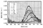
도 15는 본 발명의 실시예 1에 있어서의 형광체 조성물의 발광 스펙트럼과 여기 스펙트럼을 도시한 도면이다.Fig. 15 is a diagram showing the emission spectrum and the excitation spectrum of the phosphor composition in Example 1 of the present invention.
도 16은 본 발명의 실시예 1에 있어서의 형광체 조성물의 X선 회절 패턴을 도시한 도면이다.Fig. 16 is a diagram showing an X-ray diffraction pattern of the phosphor composition in Example 1 of the present invention.
도 17은 본 발명의 실시예 2에 있어서의 형광체 조성물의 발광 스펙트럼과 여기 스펙트럼을 도시한 도면이다.Fig. 17 is a diagram showing the emission spectrum and the excitation spectrum of the phosphor composition in Example 2 of the present invention.
도 18은 본 발명의 실시예 2에 있어서의 형광체 조성물의 X선 회절 패턴을 도시한 도면이다.18 is a diagram showing an X-ray diffraction pattern of the phosphor composition in Example 2 of the present invention.
도 19는 본 발명의 실시예 2에 관한 형광체 조성물의 발광 스펙트럼을 도시한 도면이다.Fig. 19 shows the emission spectrum of the phosphor composition according to Example 2 of the present invention.
도 20은 본 발명의 실시예 2에 관한 형광체 조성물의 Eu 치환량과 발광 피크 파장의 관계를 도시한 도면이다.Fig. 20 is a graph showing the relationship between the Eu substitution amount and the emission peak wavelength of the phosphor composition according to Example 2 of the present invention.
도 21은 본 발명의 실시예 2에 관한 형광체 조성물의 Eu 치환량과 발광 강도와의 관계를 도시한 도면이다.Fig. 21 is a graph showing the relationship between the Eu substitution amount and the luminescence intensity of the phosphor composition according to Example 2 of the present invention.
도 22는 본 발명의 실시예 3에 있어서의 형광체 조성물의 발광 스펙트럼과 여기 스펙트럼을 도시한 도면이다.Fig. 22 is a diagram showing the emission spectrum and the excitation spectrum of the phosphor composition in Example 3 of the present invention.
도 23은 본 발명의 실시예 4에 있어서의 형광체 조성물의 발광 스펙트럼과 여기 스펙트럼을 도시한 도면이다.Fig. 23 is a diagram showing the emission spectrum and the excitation spectrum of the phosphor composition in Example 4 of the present invention.
도 24는 본 발명의 실시예 5에 있어서의 형광체 조성물의 발광 스펙트럼과 여기 스펙트럼을 도시한 도면이다.24 is a diagram showing the emission spectrum and the excitation spectrum of the phosphor composition in Example 5 of the present invention.
도 25는 본 발명의 실시예 6에 있어서의 형광체 조성물의 발광 스펙트럼과 여기 스펙트럼을 도시한 도면이다.Fig. 25 is a diagram showing the emission spectrum and the excitation spectrum of the phosphor composition in Example 6 of the present invention.
도 26은 본 발명의 실시예 7에 있어서의 형광체 조성물의 발광 스펙트럼과 여기 스펙트럼을 도시한 도면이다.Fig. 26 is a diagram showing the emission spectrum and the excitation spectrum of the phosphor composition in Example 7 of the present invention.
도 27은 본 발명의 실시예 8에 있어서의 형광체 조성물의 발광 스펙트럼과 여기 스펙트럼을 도시한 도면이다.Fig. 27 is a diagram showing the emission spectrum and the excitation spectrum of the phosphor composition in Example 8 of the present invention.
도 28은 본 발명의 형광체 조성물의 조성 범위를 표시하는 3원 조성도이다.Fig. 28 is a ternary composition diagram showing the composition range of the phosphor composition of the present invention.
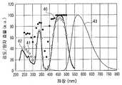
도 29는 SrSiN2 : Eu2+ 적색 형광체의 발광 특성을 도시한 도면이다.FIG. 29 is a graph showing the light emission characteristics of a SrSiN2 : Eu2+ red phosphor.
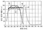
도 30은 SrAlSiN3 : Eu2+ 적색 형광체의 발광 특성을 도시한 도면이다.30 is a graphshowing the light emission characteristics of a SrAlSiN3 : Eu2+ red phosphor.
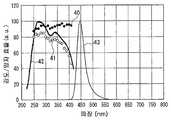
도 31은 Sr2Si5N8 : Eu2+적색 형광체의 발광 특성을 도시한 도면이다.31 is a diagram showing the light emission characteristics of a Sr2 Si5 N8 : Eu2+ red phosphor.
도 32는 (Ba, Sr)2SiO4: Eu2+ 녹색 형광체의 발광 특성을 도시한 도면이다.32 is a diagram showing the light emission characteristics of a (Ba, Sr)2 SiO4 : Eu2+ green phosphor.
도 33은 (Sr, Ba)2SiO4 : Eu2+ 황색 형광체의 발광 특성을 도시한 도면이다.33 is a graph showing the light emission characteristics of a (Sr, Ba)2 SiO4 : Eu2+ yellow phosphor.
도 34는 (Sr, Ca)2SiO4 : Eu2+ 황색 형광체의 발광 특성을 도시한 도면이다.Fig. 34 is a graph showing the light emission characteristics of the (Sr, Ca)2 SiO4 : Eu2+ yellow phosphor.
도 35는 0.75CaO·2.25AlN·3.25Si3N4 : Eu2+ 황색 형광체의 발광 특성을 도시한 도면이다.Fig. 35 is a graph showing the light emission characteristics of a 0.75CaO.2.25AlN.3.25Si3 N4 : Eu2+ yellow phosphor.
도 36은 (Y, Gd)3A15O12 : Ce3+황색 형광체의 발광 특성을 도시한 도면이다.36 is a diagram showing the light emission characteristics of a (Y, Gd)3 A15 O12 : Ce3+ yellow phosphor.
도 37은 BaMgAl10O17 : Eu2+ 청색 형광체의 발광 특성을 도시한 도면이다.37 is a graph showing the luminescence properties of BaMgAl10 O17 : Eu2+ blue phosphor.
도 38은 Sr4Al14O25 : Eu2+ 청녹색 형광체의 발광 특성을 도시한 도면이다.FIG. 38 is a graph showing luminescence properties of Sr4 Al14 O25 : Eu2+ bluish green phosphor. FIG.
도 39는 (Sr, Ba)10(PO4)6C12: Eu2+청색 형광체의 발광 특성을 도시하는 도면이다.Fig. 39 is a graph showing the luminescence properties of the (Sr, Ba)10 (PO4 )6 C12 : Eu2+ blue phosphor.
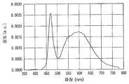
도 40은 La2O2S : Eu3+ 적색 형광체의 발광 특성을 도시한 도면이다.40 is a graph showing the light emission characteristics of a La2 O2 S: Eu3+ red phosphor.
도 41은 본 발명의 실시예 26에 있어서의 발광 장치의 사시도이다.Fig. 41 is a perspective view of a light emitting device according to
도 42는 본 발명의 실시예 26에 있어서의 발광 장치의 일부 단면도이다.42 is a partial cross-sectional view of a light emitting device according to a twenty-sixth embodiment of the present invention.
도 43은 본 발명의 실시예 26에 있어서의 발광 장치의 발광 스펙트럼이다.Fig. 43 is a light emission spectrum of the light emitting device of Example 26 of the present invention.
도 44는 본 발명의 비교예 6에 있어서의 발광 장치의 발광 스펙트럼이다.Fig. 44 is a light emission spectrum of the light emitting device in Comparative Example 6 of the present invention.
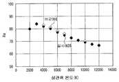
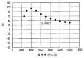
도 45는 본 발명의 실시예 26 및 비교예 6에 있어서의, 상관색 온도와 상대 광속과의 관계를 시뮬레이션한 결과를 도시하는 도면이다.FIG. 45 is a diagram showing a result of simulating the relationship between the correlated color temperature and the relative luminous flux in Example 26 and Comparative Example 6 of the present invention. FIG.
도 46은 본 발명의 실시예 26 및 비교예 6에 있어서의, 상관색 온도와 Ra와의 관계를 시뮬레이션한 결과를 도시하는 도면이다.It is a figure which shows the result of simulating the relationship of correlated color temperature and Ra in Example 26 and the comparative example 6 of this invention.
도 47은 본 발명의 실시예 27에 있어서의, 상관색 온도와 Ra와의 관계를 시뮬레이션한 결과를 도시하는 도면이다.Fig. 47 is a diagram showing a result of simulating the relationship between the correlated color temperature and Ra in Example 27 of the present invention.
도 48은 본 발명의 실시예 27에 있어서의, 상관색 온도와 R9와의 관계를 시뮬레이션한 결과를 도시하는 도면이다.FIG. 48 is a diagram showing a result of simulating the relationship between the correlated color temperature and R9 in Example 27 of the present invention. FIG.
도 49는 본 발명의 실시예 27에 있어서의, 상관색 온도와 상대 광속과의 관계를 시뮬레이션한 결과를 도시한 도면이다.FIG. 49 shows the results of simulating the relationship between the correlated color temperature and the relative luminous flux in Example 27 of the present invention. FIG.
도 50은 본 발명의 실시예 27에 있어서의 발광 장치의 발광 스펙트럼이다.50 is a light emission spectrum of the light emitting device of Example 27 of the present invention.
도 51은 본 발명의 실시예 28에 있어서의 발광 장치의 발광 스펙트럼이다.Fig. 51 shows light emission spectra of the light emitting device in Example 28 of the present invention;
도 52는 본 발명의 비교예 7에 있어서의 발광 장치의 발광 스펙트럼이다.Fig. 52 is a light emission spectrum of the light emitting device in Comparative Example 7 of the present invention.
도 53은 본 발명의 실시예 28 및 비교예 7에 있어서의, 상관색 온도와 상대 광속과의 관계를 시뮬레이션한 결과를 도시한 도면이다.FIG. 53 shows the results of a simulation of the relationship between the correlated color temperature and the relative luminous flux in Example 28 and Comparative Example 7 of the present invention. FIG.
도 54는 본 발명의 실시예 28 및 비교예 7에 있어서의, 이상적인 형광체를 이용한 발광 장치의 상관색 온도와 상대 광속과의 관계를 시뮬레이션한 결과를 도시한 도면이다.Fig. 54 shows the results of simulating the relationship between the correlated color temperature and the relative luminous flux of the light-emitting device using the ideal phosphor in Example 28 and Comparative Example 7 of the present invention.
도 55는 본 발명의 실시예 28 및 비교예 7에 있어서의, 상관색 온도와 Ra와의 관계를 시뮬레이션한 결과를 도시한 도면이다.FIG. 55 is a diagram showing a result of simulating the relationship between the correlated color temperature and Ra in Example 28 and Comparative Example 7 of the present invention. FIG.
도 56은 본 발명의 실시예 28 및 비교예 7에 있어서의, 상관색 온도와 R9와의 관계를 시뮬레이션한 결과를 도시한 도면이다.Fig. 56 shows the results of simulating the relationship between the correlated color temperature and R9 in Example 28 and Comparative Example 7 of the present invention.
도 57은 본 발명의 실시예 28에 있어서의, 상관색 온도 4500K(duv= 0)의 난색계 백색광을 발하는 발광 장치의 발광 스펙트럼을 시뮬레이션한 결과를 도시한 도면이다.Fig. 57 shows the results of simulation of the emission spectrum of a light emitting device that emits warm color white light having a correlation color temperature of 4500K (duv = 0) in Example 28 of the present invention.
도 58은 본 발명의 실시예 28에 있어서의, 상관색 온도 5500K(duv= 0)의 난색계 백색광을 발하는 발광 장치의 발광 스펙트럼을 시뮬레이션한 결과를 도시한 도면이다.FIG. 58 shows the results of simulation of the emission spectrum of a light emitting device that emits warm color white light having a correlation color temperature of 5500 K (duv = 0) in Example 28 of the present invention.
이하, 본 발명의 실시의 형태에 관해서 설명한다.EMBODIMENT OF THE INVENTION Hereinafter, embodiment of this invention is described.
(실시형태 1)(Embodiment 1)
우선, 본 발명의 형광체 조성물의 실시의 형태에 관해서 설명한다. 본 발명의 형광체 조성물의 일례는, 형광체 모체와 발광 중심 이온을 포함하고, aM3N2·bAlN·cSi3N4의 조성식으로 나타내는 조성물을 형광체 모체의 주체로서 포함하는 형광체 조성물로서, 상기 조성식에 있어서, M은, Mg, Ca, Sr, Ba, 및 Zn으로 이루어지는 군에서 선택되는 적어도 하나의 원소이고, a, b, c는, 각각 0.2≤a/(a+b)≤0.95, 0.05≤b/(b+c)≤0.8, 0.4≤c/(c+a)≤0.95를 만족하는 수치인 형광체 조성물이다. 이러한 조성물을 형광체 모체로서 이용하면, 예를 들면, Eu2+ 이온을 발광 중심으로 하여 첨가한 경우, 형광체 조성물은, 자외, 근자외, 자색, 또는 청색광으로 여기되고, 오렌지색 또는 적색의 난색계의 발광을 발하는 형광체가 된다.First, embodiment of the fluorescent substance composition of this invention is described. An example of the phosphor composition of the present invention is a phosphor composition comprising a phosphor matrix and luminescent center ions and comprising a composition represented by the composition formula of aM3 N2 · bAlN · cSi3 N4 as a main body of the phosphor matrix, Wherein M is at least one element selected from the group consisting of Mg, Ca, Sr, Ba, and Zn, and a, b, and c are each 0.2≤a / (a + b) ≤0.95, 0.05≤b It is a fluorescent substance composition whose numerical value satisfy | fills /(b+c)<=0.8, 0.4 <= c / (c + a) <= 0.95. When such a composition is used as a fluorescent substance matrix, for example, when Eu2+ ions are added as the emission center, the phosphor composition is excited by ultraviolet, near ultraviolet, violet, or blue light, and emits orange or red warm colors. It becomes the phosphor which emits light.
여기서, 주체로서 포함한다는 것은, 50중량%를 넘어 포함하는 것을 말하고, 75중량% 이상 포함하는 것이 바람직하고, 또한 85중량% 이상 포함하는 것이 보다 바람직하다.Here, containing as a main body means containing more than 50 weight%, It is preferable to contain 75 weight% or more, It is more preferable to contain 85 weight% or more.
발광 효율이나 발광색의 색조의 면에서 바람직한 상기 a, b, c는, 0.2≤a/(a+b)≤0.6, 0.3≤b/(b+c)≤0.8, 0.4≤c/(c+a)≤0.8을 만족하는 수치이고, 보다 바람직하게는, 0.2≤a/(a+b)≤0.3, 0.6≤b/(b+c)≤0.8, 0.4≤c/(c+a)≤0.6을 만족하는 수치이다.A, b, and c, which are preferable in terms of light emission efficiency and color tone of light emission color, are 0.2 ≦ a / (a + b) ≦ 0.6, 0.3 ≦ b / (b + c) ≦ 0.8, 0.4 ≦ c / (c + a ) ≤0.8, more preferably 0.2≤a / (a + b) ≤0.3, 0.6≤b / (b + c) ≤0.8, 0.4≤c / (c + a) ≤0.6 I am satisfied.
또한, 상기 형광체 모체는, MAlSiN3의 조성식으로 나타내는 조성물이어도 된다.The phosphor matrix may be a composition represented by the compositional formula of MAlSiN3 .
또한, 본 발명의 형광체 모체의 다른 일례는, M2Si5N8, MSi7N10, M1.5A13Si9N16, MA12Si10N16, MSi3N5, M2Si4N7, MSi6AlON9, M2Si4AlON7, MSiN2의 조성식으로 나타내는 조성물을 포함하지 않는 형광체 모체로서, 알칼리 토류금속의 질화물 및 아연의 질화물에서 선택되는 어느 하나의 질화물과, 산화유로퓸과, 질화규소와, 알루미늄의 질화물을, 각각의 몰비가, 2(1-x):3x:2:6(x는, 0<x<0.1)이 되는 비율로 혼합한 혼합 원료를, 1600℃의 질소 수소 혼합 가스 중에서 2시간 소성함으로써 생성하는 조성물이다.Further, another example of the phosphor matrix of the present invention is M2 Si5 N8 , MSi7 N10 , M1.5 A13 Si9 N16 , MA12 Si10 N16 , MSi3 N5 , M2 Si4 N7, MSi 6 AlON 9, M 2
발광 효율이나 발광색의 색조의 면에서 바람직한 상기 원소 M은, Ca 및 Sr에서 선택되는 적어도 하나의 원소이고, 순도가 좋은 적색광을 발하는 형광체를 얻을 목적으로도, 원소 M의 주성분을 Ca 또는 Sr로 하는 것이 바람직하다. 원소 M을, 전술의 원소 군 중의, 적어도 2개의 원소의 혼합물로서 구성하는 것도 가능하다.The above-mentioned element M which is preferable in terms of luminous efficiency and color tone of the luminescent color is at least one element selected from Ca and Sr, and the main component of the element M is Ca or Sr for the purpose of obtaining a phosphor which emits red light with good purity It is preferable. It is also possible to comprise the element M as a mixture of at least two elements in the above-mentioned element group.
또한, 원소 M의 주성분을 Ca 또는 Sr로 한다는 것은, 원소 M의 과반수, 바람직하게는 80원자% 이상을 Ca 또는 Sr로 하는 것을 의미한다. 또한, 원료 관리나 제조의 면에서 바람직한 조성은, 원소 M의 전체를 전술의 원소 군 중의, 하나의 원소로 한 조성이고, 예를 들면 원소 M의 전체를 Ca 또는 Sr로 한 조성이다.In addition, to make Ca or Sr the main component of the element M means that the majority of the element M is made into Ca or Sr, preferably 80 atomic% or more. In terms of raw material management and production, a preferable composition is a composition in which the entirety of the element M is one element in the above-described element group, and is a composition in which the entirety of the element M is Ca or Sr, for example.
또한, 상기 MAlSiN3의 조성식으로 나타내는 조성물은, 상기 MAlSiN3의 화학식으로 나타내는 화합물을 포함하는 것이 바람직하고, 상기 화합물을 주체로서 포함하는 것이 보다 바람직하다. 본 실시 형태의 형광체 조성물은 불순물을 포함하지 않는 것이 바람직하지만, 예를 들면, 원소 M, A1, Si 또는 N중 적어도 어느 하나에 대해 10원자% 미만에 해당하는 양의 금속 불순물 원소나 가스화하는 불순물 원소를 적어도 한개 포함해도 된다. 또한, 상기 조성물이 상기 MAlSiN3의 화학식으로 나타내는 화합물인 경우에는, 10원자%를 넘지 않는 범위에 있어서 상기 화학식 MAlSiN3중의 A1, Si 또는 N에 과부족이 있더라도, 형광체 모체가 MAlSiN3의 화학식으로 나타내는 화합물을 주체로 하면 된다. 즉, 형광체의 발광 성능의, 약간의 개량을 목적으로 하여, 미량 혹은 소량의 불순물 첨가나 화학량론적 조성으로부터 조금 벗어난 조성으로 하는 것도 가능하다.Further, the composition represented by the composition formula is MAlSiN3, it is preferred that the MAlSiN comprising a compound represented by the formula of3, and more preferably containing the above compound as a principal. It is preferable that the fluorescent substance composition of this embodiment does not contain an impurity, For example, the metal impurity element of the quantity corresponding to less than 10 atomic% with respect to at least any one of element M, A1, Si, or N, or the gaseous impurity At least one element may be included. Further, in the case where the composition is a compound represented by the formula of the MAlSiN3, in the range of not more than 10 at%, even if the above formula MAlSiN3 of A1, excess or deficiency in the Si or N, the fluorescent substance matrix is represented by the formula of MAlSiN3 It is good to make a compound into a main body. That is, for the purpose of slight improvement of the luminescence performance of the phosphor, it is also possible to make the composition slightly deviated from the addition of a small amount or a small amount of impurities or the stoichiometric composition.
예를 들면, 본 실시 형태의 형광체 조성물은, 발광 성능의 약간의 개량을 목적으로 하여, Si의 일부를, 예를 들면 Ge나 Ti 등 4가의 가수를 구할 수 있는 적어도 하나의 원소로 치환하는 것도 가능하고, Al의 일부를, 예를 들면, B, Ga, In, Sc, Y, Fe, Cr, Ti, Zr, Hf, V, Nb, Ta 등의 3가의 가수를 구할 수 있는 적어도 하 나의 원소로 치환하는 것도 가능하다. 여기서, 상기 일부란, 예를 들면, Si나 A1에 대한 원자수가 30원자% 미만인 것을 의미한다.For example, in the phosphor composition of the present embodiment, a part of Si is replaced with at least one element capable of obtaining a tetravalent valence such as, for example, Ge or Ti, for the purpose of slightly improving the light emission performance. At least one element capable of obtaining a part of Al, for example, a trivalent valence such as B, Ga, In, Sc, Y, Fe, Cr, Ti, Zr, Hf, V, Nb, Ta, etc. It is also possible to substitute by. Here, the said part means that the atomic number with respect to Si and A1 is less than 30 atomic%, for example.
상기 조성물의 실질적인 조성 범위는, MAl1±0.3Si1±0.3N3(1±0.3)O0∼0.3, 바람직하게는 MAl1±0.1Si1±0.1N3(1±0.1)O0∼0.1의 조성식으로 나타내는 조성 범위이다.Substantial composition range of the composition is MAl1± 0.3 Si1± 0.3 N3(1 ± 0.3) O 0~0.3 , preferably MAl1 ± 0.1 Si1 ± 0.1 N3 (1 ± 0.1) O 0~0.1 It is a composition range represented by the composition formula of.
또한, 상기 조성물은, 특히 SrAlSiN3 또는 CaAlSiN3의 조성식 또는 화학식으로 나타내는 것이 바람직하다. 예를 들면, (Sr, Ca)AlSiN3, (Sr, Mg)AlSiN3, (Ca, Mg)AlSiN3, (Sr, Ca, Ba)AlSiN3 등, 알칼리 토류금속 원소를 복수개 갖는 조성물이어도 된다. 또한, 상기 조성식 중의 O(산소)는, 형광체 조성물의 제조 중에 들어가는 불순 원소이다.Further, the composition, particularly preferably represented by formula or formula of SrAlSiN3 or CaAlSiN3. For example, a composition having a plurality of alkaline earth metal elements, such as (Sr, Ca) AlSiN3 , (Sr, Mg) AlSiN3 , (Ca, Mg) AlSiN3 , (Sr, Ca, Ba) AlSiN3 , may be used. In addition, O (oxygen) in the said composition formula is an impurity element entered during manufacture of a fluorescent substance composition.
상기 형광체 모체를 구성하는 화합물 결정의 격자 중에, 발광 중심이 될 수 있는 이온(발광 중심 이온)을 적어도 하나 첨가하여 형광체 조성물을 구성한다. 이와 같이 형광체 모체 중에 발광 중심 이온을 첨가하면, 형광을 발하는 형광체가 된다.In the lattice of the compound crystal constituting the phosphor matrix, at least one ion (luminescence center ion) which can serve as a luminescence center is added to form a phosphor composition. In this way, when the luminescence center ions are added to the phosphor matrix, the phosphor emits fluorescence.
발광 중심 이온으로는, 각종 희토류이온이나 전이금속이온에서 선택되는 금속 이온을 필요에 따라 적절히 선택할 수 있다. 발광 중심 이온의 구체예를 들면, Ce3+, Pr3+, Nd3+, Sm3+, EU3+, Gd3+, Tb3+, Dy3+, Ho3+, Er3+, Tm3+, Yb3+ 등의 3가 희토류금속 이온, Sm2+, Eu2+, Yb2+ 등의 2가 희토류금속 이온, Mn2+ 등의 2가 전이금속이 온, Cr3+이나 Fe3+ 등의 3가 전이금속이온, Mn4+ 등의 4가 전이금속이온 등이다.As the emission center ions, metal ions selected from various rare earth ions and transition metal ions can be appropriately selected as necessary. Specific examples of luminescent center ions include Ce3+ , Pr3+ , Nd3+ , Sm3+ , EU3+ , Gd3+ , Tb3+ , Dy3+ , Ho3+ , Er3+ , Tm3+, trivalent rare earth metal ions, such as3 + Yb, Sm+2, Eu+2, Yb+2, such as a divalent rare earth metal ions, such as
본 실시 형태의 형광체 조성물은, 발광 효율의 면에서 바람직하게는, 발광 중심 이온을, Ce3+ 및 Eu2+에서 선택되는 적어도 하나의 이온으로 한다. 또한, 이러한 이온을 포함하는 형광체로 하면, 백색 LED용으로서 바람직한 형광체로도 된다. Eu2+를 발광 중심 이온으로 하면, 난색계 광을 발하는 형광체를 얻을 수 있고, 발광 장치, 특히 조명 장치용으로서 바람직한 형광체가 된다. Ce3+를 발광 중심 이온으로 하면, 청녹계광을 발하는 형광체를 얻을 수 있고, 연색성이 높은 발광 장치, 특히 조명 장치용으로서 바람직한 형광체가 된다.In terms of luminous efficiency, the phosphor composition of the present embodiment, preferably, the emission center ion is at least one ion selected from Ce3+ and Eu2+ . Moreover, if it is set as fluorescent substance containing such an ion, it will be set as fluorescent substance suitable for a white LED. When Eu2+ is used as the emission center ion, a phosphor that emits warm color light can be obtained, and a phosphor that is suitable for a light emitting device, particularly a lighting device, is obtained. When Ce3+ is used as the emission center ion, a phosphor emitting blue-green light can be obtained, and a phosphor having high color rendering property, in particular, a phosphor suitable for an illumination device.
본 실시 형태의 형광체 조성물은, 발광색의 면에서 바람직하게는, 발광 중심 이온을, Ce3+, Eu2+, Eu3+ 및 Tb3+에서 선택되는 적어도 하나의 이온으로 한다. Ce3+를 발광 중심 이온으로 하면, 적어도 청녹계광을 발하는 고효율 형광체를 얻을 수 있고, Eu2+를 발광 중심 이온으로 하면, 오렌지∼적색계 광을 발하는 고효율 형광체를 얻을 수 있고, Eu3+를 발광 중심 이온으로 하면, 적색계 광을 발하는 고효율 형광체를 얻을 수 있고, Tb3+를 발광 중심 이온으로 하면, 녹색광을 발하는 고효율 형광체를 얻을 수 있다. 어떠한 형광체나, 광의 삼원색이 되는, 색순도가 높은 적 또는 녹 또는 청, 혹은 수요가 많은 오렌지계중 어느 하나의 광을 발하므로, 발광 장치용으로서 바람직한 형광체가 된다.The phosphor composition of the present embodiment preferably has a light emission center ion as at least one ion selected from Ce3+ , Eu2+ , Eu3+ and Tb3+ . When Ce3+ is used as the emission center ion, a high efficiency phosphor that emits at least blue green light can be obtained. When Eu2+ is used as the emission center ion, a high efficiency phosphor that emits orange to red light can be obtained, and Eu3+ is emitted. When the center ion is used, a high efficiency phosphor emitting red light can be obtained. When Tb3+ is a light emitting center ion, a high efficiency phosphor emitting green light can be obtained. Any phosphor emits light of either red, green or blue with high color purity, or an orange system in high demand, which serves as the three primary colors of light, making it a preferable phosphor for a light emitting device.
바람직한 발광 중심 이온의 첨가량은 발광 중심 이온의 종류에 따라 다르지만, 예를 들면, 발광 중심 이온을 Eu2+이나 Ce3+로 한 경우, 전술의 원소 M에 대해, 0.1원자%이상 30원자%이하, 바람직하게는 0.5원자%이상 10원자%이하이다. 이보다도 첨가량이 적거나 많아도, 양호한 발광색과 고휘도가 양립하는 형광체로 되지 않는다. 또한, 기본적으로는, 발광 중심 이온을, 원소 M의 격자 위치의 일부를 치환하도록 하여 첨가하는 것이 바람직한데, A1 또는 Si 중 어느 하나의 격자 위치의 일부를 치환하도록 하여 첨가하는 것도 가능하다.The amount of the preferable emission center ion added varies depending on the type of emission center ion. For example, when the emission center ion is set to Eu2+ or Ce3+ , 0.1 atom% or more and 30 atom% or less with respect to the above-described element M Preferably, it is 0.5 atomic% or more and 10 atomic% or less. Even if the addition amount is smaller or larger than this, it is not a phosphor having good emission color and high luminance. Basically, it is preferable to add the luminescence center ions so as to replace a part of the lattice position of the element M, but it is also possible to add a part of the lattice position of either A1 or Si.
본 실시 형태의 형광체 조성물은, 복수의 발광 중심 이온을 공부활(共付活)한 형광체로 하는 것도 가능하다. 발광 중심 이온을 공부활한 형광체의 일례로는, Ce3+ 이온과 Eu2+ 이온을 공부활한 형광체, Eu2+ 이온과 Dy3+ 이온을 공부활한 형광체, Eu2+ 이온과 Nd3+ 이온을 공부활한 형광체, Ce3+ 이온과 Mn2+ 이온을 공부활한 형광체, Eu2+ 이온과 Mn2+ 이온을 공부활한 형광체 등을 들 수 있다. 이와 같이 하면, 한쪽 발광 중심 이온으로부터 별도의 이온으로의 에너지 전이가 생기는 현상을 이용하여, 여기 스펙트럼이나 발광 스펙트럼의 형상을 제어한 형광체를 얻거나, 열에 의한 여기 현상을 이용하여, 잔광이 긴 장잔광 형광체를 얻을 수 있는 경우가 있다.The fluorescent substance composition of this embodiment can also be set as the fluorescent substance which studied several light emitting center ion. Examples of phosphors that have studied luminescence center ions include phosphors that havestudied Ce3+ ions and Eu2+ ions, phosphors that havestudied Eu2+ ions and Dy3+ ions, Eu2+ ions and Nd3 + ion balls revive the phosphor, there may be mentioned ions Ce3+ and Mn2+ ions balls revive the phosphor, a Eu2+ ions and Mn2+ ions ball revive a phosphor or the like. In this way, the phosphor which controlled the shape of an excitation spectrum or an emission spectrum by using the phenomenon which the energy transfer from one emission center ion to another ion is obtained, or the long afterglow field is utilized using the excitation phenomenon by heat. An afterglow phosphor may be obtained.
본 발명에 관한 발광 장치용으로서 바람직한 형광체는, 이하에 기재하는 형광체이다. 상기 a, b, c의 수치, 또는 원소 M을 점유하는 원소나 발광 중심 이온 의 종류나 첨가량을 바꿈으로써, 이러한 형광체를 얻을 수 있다.The fluorescent substance preferable for the light emitting device which concerns on this invention is a fluorescent substance described below. Such fluorescent substance can be obtained by changing the numerical value of said a, b, c, or the kind and addition amount of the element which occupies the element M, or light emission center ion.
(1) 580㎚이상 660㎚미만, 발광 장치용으로서 요구되는 색순도와 시감도(視感度)의 면에서, 바람직하게는 610㎚이상 650㎚이하의 파장 영역에 발광 피크를 갖는 난색계, 특히 적색계광을 발하는 형광체.(1) In view of color purity and visibility required for a light emitting device of 580 nm or more and less than 660 nm, a warm color system having a light emission peak in a wavelength range of preferably 610 nm or more and 650 nm or less, particularly red light Phosphor that emits.
(2) 350㎚이상 420㎚미만, 발광 장치용으로서 요구되는 여기 특성의 면에서, 바람직하게는 380㎚이상 410㎚미만의 근자외광 또는 자색광의 조사에 의해서 여기 가능한 형광체.(2) A phosphor capable of excitation by irradiation of near-ultraviolet light or violet light, preferably 380 nm or more and less than 420 nm, in terms of excitation characteristics required for a light emitting device.
(3) 420㎚이상 500㎚미만, 발광 장치용으로서 요구되는 여기 특성의 면에서, 바람직하게는 440㎚이상 480㎚미만의 청색계광의 조사에 의해서 여기 가능한 형광체.(3) A phosphor capable of excitation by irradiation with blue light of preferably 440 nm or more and less than 500 nm and preferably 440 nm or more and less than 480 nm in view of the excitation characteristics required for the light emitting device.
(4) 500㎚이상 560㎚미만의 녹색계광의 조사에 의해서 여기 가능한 형광체.(4) Phosphor which can be excited by irradiation of green light of 500 nm or more and less than 560 nm.
또한, 본 실시 형태의 형광체 조성물의 성상에 대해서는, 특별히 한정되지 않는다. 단결정 벌크나, 세라믹스 성형체나, 두께 몇㎚∼몇㎛의 박막이거나, 두께 몇십㎛∼몇백㎛의 두꺼운 막이라도, 분말이라도 상관없지만, 발광장치에의 응용에 이용하는 목적에서는, 분말인 것이 바람직하고, 보다 바람직하게는, 중심 입경(D5o)이 0.1㎛이상 30㎛이하, 바람직하게는 0.5㎛이상 20㎛ 이하인 분말이다. 또한, 형광체 조성물의 입자 자체의 형상도 특별히 한정되지 않고, 구형상, 판상, 봉 형상 등의 어떠한 것이어도 된다.In addition, the property of the fluorescent substance composition of this embodiment is not specifically limited. Although it may be a single crystal bulk, a ceramic molded body, a thin film of several nm to several micrometers in thickness, or a thick film of several tens of micrometers to several hundred micrometers in thickness, it may be a powder, but it is preferable that it is a powder for the purpose of using for a light-emitting device, More preferably, it is a powder whose center particle diameterD5o is 0.1 micrometer or more and 30 micrometers or less, Preferably they are 0.5 micrometer or more and 20 micrometers or less. Moreover, the shape of the particle | grains itself of a fluorescent substance composition is not specifically limited, either, spherical shape, plate shape, rod shape, etc. may be sufficient.
이렇게 하여 제조할 수 있는 본 실시 형태의 형광체 조성물은, 적어도 250㎚이상 600㎚이하의 자외∼근자외∼자색∼청색∼녹색∼황색∼오렌지색의 광에 의해서 여기 가능하고, 적어도, 청녹, 오렌지색 또는 적색의 발광을 발하는 형광체가 된다. 610㎚이상 650㎚ 이하의 파장 영역에 발광 피크를 갖는 적색계광을 방사하는 형광체도 얻을 수 있다. 또한, Eu2+ 이온을 발광 중심으로 하고, 상기 적색계광을 방사하는 형광체의 여기 스펙트럼 및 발광 스펙트럼의 형상은, 종래의 Sr2Si5N8니트리드실리케이트(nitridosilicate)를 모체 재료로 하는 Eu2+부활 형광체와 비교적 유사한 것이 된다.The fluorescent substance composition of this embodiment which can be manufactured in this way can be excited by the light of ultraviolet-near-ultraviolet-purple-blue-green-yellow-orange at least 250 nm or more and 600 nm or less, and at least blue-green, orange or It becomes a phosphor emitting red light. Phosphors emitting red light having a light emission peak in a wavelength region of 610 nm or more and 650 nm or less can also be obtained. Further, Eu2+ ions as a luminescent center, and shape of the excitation spectrum and the emission spectrum of the phosphor to emit the red light is, Eu2 that the conventional Sr2 Si5 N8 nitride silicates (nitridosilicate) as a matrix material+ Relatively similar to the activating phosphor.
다음에, 본 실시 형태의 형광체 조성물의 제조 방법에 대해서 설명한다.Next, the manufacturing method of the fluorescent substance composition of this embodiment is demonstrated.
<본 발명의 제조 방법 1><
본 실시 형태의 형광체 조성물은, 예를 들면, 이하에 설명하는 제조 방법으로 제조할 수 있다.The fluorescent substance composition of this embodiment can be manufactured by the manufacturing method demonstrated below, for example.
우선, 형광체 모체를 형성하기 위한 원료로서, 알칼리 토류금속 M의 질화물(M3N2) 또는 아연의 질화물(Zn3N2), 질화규소(Si3N4), 질화알루미늄(AlN)을 준비한다. 단, 상기 알칼리 토류금속의 질화물이나 아연의 질화물은, 세라믹스 원료로서 많이 이용되지 않아, 입수가 곤란할 뿐만 아니라 고가이고, 또한 대기 중의 수증기와 용이하게 반응하여 변질하기 때문에, 대기중에서의 취급은 곤란하다는 과제를 가진다.First, nitride (M3 N2 ) or zinc nitride (Zn3 N2 ), silicon nitride (Si3 N4 ), or aluminum nitride (AlN) of alkaline earth metal M is prepared as a raw material for forming the phosphor matrix. . However, since the nitride of the alkali earth metal and the nitride of zinc are not widely used as ceramic raw materials, they are difficult to obtain and are expensive, and because they easily react and deteriorate with water vapor in the air, they are difficult to handle in the air. Have a task.
또한, 발광 중심 이온을 첨가하기 위한 원료로서, 각종 희토류금속이나 전이 금속, 또는 이들 화합물도 이용한다. 이러한 원소로는, 원자 번호 58∼60, 또는 62∼71의 란타노이드나 전이 금속, 특히 Ce, Pr, Eu, Tb, Mn이 있다. 이러한 원소를 포함하는 화합물로는, 상기 란타노이드나 전이 금속의, 산화물, 질화물, 수산화물, 탄산염, 수산염, 질산염, 황산염, 할로겐화물, 인산염 등이 있다. 구체적으로는, 예를 들면, 탄산세륨, 산화유로퓸, 질화유로퓸, 금속테르븀, 탄산망간 등이다.Moreover, various rare earth metals, transition metals, or these compounds are also used as a raw material for adding light emission center ion. Such elements include lanthanoids and transition metals of
다음에, 각 원자의 원자 비율이, a(M1-xLcx)3N2·bAlN·cSi3N4가 되도록, 이들 형광체 원료를 칭량하고, 혼합하여, 혼합 원료를 얻는다. 단, M은, Mg, Ca, Sr, Ba, 및 Zn으로 이루어지는 군에서 선택되는 적어도 하나의 원소이고, a, b, c는, 0.2≤a/(a+b)≤0.95, 0.05≤b/(b+c)≤0.8, 0.4≤c/(c+a)≤0.95을 만족하는 수치, Lc는 발광 중심 이온이 되는 원소를 나타내고, x는, 0<x<0.3, 바람직하게는 0.001≤x≤0.2, 보다 바람직하게는 0.005≤x≤0.1을 만족하는 수치를 나타낸다. 예를 들면, 원자 비율을 M1-xLcxAlSiN3로 한다.Next, these phosphor raw materials are weighed and mixed so that the atomic ratio of each atom becomes a (M1-x Lcx )3 N2 · bAlN · cSi3 N4 , and a mixed raw material is obtained. However, M is at least one element selected from the group consisting of Mg, Ca, Sr, Ba, and Zn, and a, b, and c are 0.2 ≦ a / (a + b) ≦ 0.95, 0.05 ≦ b / A numerical value satisfying (b + c) ≦ 0.8, 0.4 ≦ c / (c + a) ≦ 0.95, Lc represents an element serving as a light emitting center ion, x is 0 <x <0.3, preferably 0.001 ≦ x ≤ 0.2, more preferably a numerical value satisfying 0.005 ≤ x ≤ 0.1. For example, the atomic ratio is M1-x Lcx AlSiN3 .
계속해서, 상기 혼합 원료를, 진공 분위기, 중성 분위기(불활성 가스나 질소 가스중 등), 환원 분위기(C0 중, 질소 수소 혼합 가스중 등)중 어느 하나의 분위기 중에서 소성한다.Subsequently, the mixed raw material is fired in any one of a vacuum atmosphere, a neutral atmosphere (in an inert gas, nitrogen gas, etc.), and a reducing atmosphere (in C0, nitrogen-hydrogen mixed gas, etc.).
또한, 바람직한 상기 분위기는, 단순한 설비를 이용할 수 있는 이유로, 상압 분위기인데, 고압 분위기, 가압 분위기, 감압 분위기, 진공 분위기중 어떠한 것이어도 된다. 형광체의 고성능화를 목적으로 한 바람직한 반응 분위기는, 고압 분위기이고, 예를 들면, 2기압 이상 100기압 이하, 분위기의 취급의 면을 고려하면, 바 람직하게는 5기압 이상 20기압 이하의, 질소 가스를 주체로 하여 이루어지는 분위기이다. 이러한 고압 분위기로 하면, 고온 소성중에 생기는 질화물 형광체 조성물의 분해를 방지 또는 억제할 수 있고, 형광체 조성물의 조성 편차를 억제하여, 발휘 성능이 높은 형광체 조성물을 제조할 수 있다.In addition, the said preferable atmosphere is an atmospheric pressure atmosphere for the reason that a simple installation can be used, and any of a high pressure atmosphere, a pressurized atmosphere, a reduced pressure atmosphere, and a vacuum atmosphere may be sufficient. The preferred reaction atmosphere for the purpose of improving the performance of the phosphor is a high pressure atmosphere, for example, from 2 atmospheres to 100 atmospheres, considering the handling of the atmosphere, preferably 5 to 20 atmospheres of nitrogen gas. It is an atmosphere mainly composed of. By setting it as such a high pressure atmosphere, decomposition | disassembly of the nitride fluorescent substance composition which arises during high temperature baking can be prevented or suppressed, the composition variation of a fluorescent substance composition can be suppressed, and the fluorescent substance composition with high performance can be manufactured.
또한, 발광 중심 이온으로서, 예를 들면, Ce3+, Eu2+, Tb3+, Mn2+ 등의 이온을 많이 생성할 목적으로, 바람직한 분위기는 환원 분위기이다. 소성 온도는, 예를 들면, 1300℃이상 2000℃이하이고, 형광체의 고성능화의 목적으로, 바람직하게는 1600℃이상 2000℃이하, 보다 바람직하게는 1700℃이상 1900℃이하이다. 한편, 대량 생산의 목적으로는, 바람직하게는 1400℃이상 1800℃이하, 보다 바람직하게는 1600℃이상 1700℃이하이다. 소성 시간으로는, 예를 들면, 30분 이상 100시간 이하, 생산성을 고려하면 바람직한 소성 시간은 2시간 이상 8시간 이하이다. 소성은 다른 분위기 중이나 같은 분위기 중에서 몇회에 나누어 행해도 된다. 이러한 소성에 의해서 얻어지는 소성물이 형광체 조성물이 된다.In addition, for the purpose of generating a large number of ions such as Ce3+ , Eu2+ , Tb3+ , Mn2+, and the like as the emission center ions, a preferable atmosphere is a reducing atmosphere. The firing temperature is, for example, 1300 ° C or more and 2000 ° C or less, and for the purpose of high performance of the phosphor, preferably 1600 ° C or more and 2000 ° C or less, and more preferably 1700 ° C or more and 1900 ° C or less. On the other hand, for the purpose of mass production, the temperature is preferably 1400 ° C or more and 1800 ° C or less, and more preferably 1600 ° C or more and 1700 ° C or less. As baking time, for example, 30 minutes or more and 100 hours or less, and when productivity is considered, preferable baking time is 2 hours or more and 8 hours or less. The firing may be performed several times in different atmospheres or in the same atmosphere. The fired product obtained by such firing becomes a fluorescent substance composition.
또한, 본 실시 형태의 형광체 조성물은, 상기 제조 방법에 의해서 제조된 것에 한정되는 것이 아니다. 상기에서 설명한 고상 반응뿐만 아니라, 예를 들면 기상 반응, 액상 반응 등을 이용한 제조 방법에 의해서도 제조 가능하다.In addition, the fluorescent substance composition of this embodiment is not limited to what was manufactured by the said manufacturing method. In addition to the solid-phase reaction described above, it can be produced by, for example, a production method using a gas phase reaction, a liquid phase reaction, or the like.
또한, Si3N4나 AlN 등의 질화물은, 알칼리토류금속의 질화물만큼은 아니지만, 순도가 높은 것을 얻는 것이 곤란하다. 상기 Si3N4나 AlN은 대기중에서는 대개의 경우, 그 극히 일부가 산화하여 SiO2나 A12O3 성분을 포함하여, 그 순도를 어느 정도 낮춘다. 이러한 이유로, 본 실시 형태의 형광체 조성물은, 실질적으로 상기 원하는 원자 비율의 조성을 갖는 형광체 조성물이면 되고, 전술의 조성식 MAlSiN3에 있어서, Si3N4나 AlN의 일부가 어느정도 산화되어, SiO2나 A12O3로 변질된 조성물을 포함하는 경우도 있다.In addition, nitrides such as Si3 N4 and AlN are not as good as nitrides of alkaline earth metals, but it is difficult to obtain high purity ones. The Si3 N4 and AlN are usually partially oxidized in the air to contain SiO2 or A12 O3 , which lowers the purity to some extent. For this reason, the phosphor composition of the present embodiment is substantially the composition of the phosphor composition having the desired atomic ratio is, in the composition formula MAlSiN3 of the above, a part of Si3 N4 or AlN is somewhat oxide, SiO2 and A1In some cases, the composition may be modified with2 O3 .
<본 발명의 제조방법 2><
본 실시 형태의 형광체 조성물은, 예를 들면, 이하에 설명하는 제조 방법으로 제조할 수 있다.The fluorescent substance composition of this embodiment can be manufactured by the manufacturing method demonstrated below, for example.
본 발명의 제조방법 2는, 전술의 aM3N2·bAlN·cSi3N4, 특히, MAlSiN3의 조성식으로 나타내는 조성물을 형광체 모체의 주체로서 포함하는 형광체 조성물의 제조 방법이고, 가열에 의해서 Mg, Ca, Sr, Ba, 및 Zn에서 선택되는 적어도 하나의 원소 M의 산화물을 생성할 수 있는 화합물과, 규소 화합물과, 알루미늄 화합물과, 발광 중심 이온을 형성하는 원소를 포함하는 화합물과, 탄소를 포함하는 원료를, 질화성 가스분위기 중에서 반응시키는 형광체 조성물의 제조 방법이다.And the production method of the
본 발명의 제조방법 2의 일례는, 가열에 의해서 금속산화물 MO(단, M은, Mg, Ca, Sr, Ba, Zn)를 생성할 수 있는 알칼리 토류금속 화합물 또는 아연 화합물, 바람직하게는, 가열에 의해서 CaO 또는 SrO를 생성할 수 있는 알칼리 토류금속 화합물을, 질화성 가스 분위기 중에 있어서의 탄소와의 반응에 의해서 환원 및 질화하면서, 상기 알칼리 토류금속 화합물 또는 아연화합물을, 규소 화합물, 알루미늄 화합물, 발광 중심 이온을 형성하는 원소를 포함하는 화합물과 반응시키는 것이다.An example of the
본 발명의 제조방법 2는, 예를 들면, 환원 질화법이라고 부를 수 있는 전술의 a(M1-xLcx)3N2·bAlN·cSi3N4, 특히 M1-xLcxAlSiN3 형광체의 제조 방법이고, 특히, 분말상의 형광체 조성물의 공업 생산에 알맞는 제조 방법이다.In the
이하, 본 발명의 제조방법 2를 상세히 설명한다.Hereinafter, the
우선, 형광체 모체를 형성하기 위한 원료로서, 가열에 의해서 전술의 원소 M의 산화물을 생성할 수 있는 화합물과, 규소 화합물과, 알루미늄 화합물을 준비한다. 또한, 가열에 의해서 상기 원소 M의 산화물을 생성할 수 있는 화합물(후술)은, 세라믹스 원료로서 많이 이용되는 것이 좋다. 이러한 원료는 입수가 용이할 뿐만 아니라 염가이고, 또한 대기 중에서 안정되므로, 대기 중에서의 취급이 용이하다.First, as a raw material for forming the phosphor matrix, a compound capable of producing the above-described oxide of element M by heating, a silicon compound, and an aluminum compound are prepared. In addition, it is preferable that the compound (after-mentioned) which can produce the oxide of the said element M by heating is used a lot as a ceramic raw material. Such raw materials are easy to obtain, inexpensive, and stable in the air, and therefore easy to handle in the air.
또한, 발광 중심 이온을 첨가하기 위한 원료로서, 전술의 각종 희토류금속이나 전이 금속, 또는 이들 화합물을 준비한다. 또한, 환원제로서, 탄소를 준비한다.In addition, various rare earth metals, transition metals, or these compounds described above are prepared as raw materials for adding luminescent center ions. In addition, carbon is prepared as a reducing agent.
다음에, 각 금속 원자의 원자 비율이, 예를 들면, a(M1-xLcx)3N2·bAlN·cSi3N4가 되고, 또한, 환원제의 탄소와의 반응에 의해서 일산화탄소 가스(CO)를 생성하여, 형광체 원료 중의 산소가 완전히 제거되는 비율이 되도록, 이들 형광체 원료 및 환원제를 칭량하고, 혼합하여, 혼합 원료를 얻는다. 단, Lc는 발광 중심 이온이 되는 금속 원소를 나타내고, x는, 0<x<0.3, 바람직하게는 0.001≤x≤0.2, 보다 바람직하게는 0.005≤x≤0.1을 만족하는 수치를 나타낸다.The Next, the atomic ratio of the respective metal atoms, forexample, a (M 1 - x Lc x) 3
계속해서, 상기 혼합 원료를, 질화성의 가스 분위기 중에서 소성하여 반응시킨다. 여기서 질화성 가스란, 질화 반응을 생기게 할 수 있는 가스를 의미한다.Subsequently, the mixed raw material is calcined and reacted in a nitriding gas atmosphere. Nitriding gas here means the gas which can produce a nitriding reaction.
또한, 발광 중심 이온으로서, 예를 들면, Ce3+, Eu2+, Tb3+, Mn2+ 등의 이온을 많이 생성할 목적으로, 바람직한 분위기는 환원 분위기이고, 예를 들면, 질소 수소 혼합 분위기 중에서 소성한다. 소성 온도는, 예를 들면 1300℃이상 2000℃이하이고, 형광체의 고성능화의 목적으로, 바람직하게는 1600℃이상 2000℃이하, 보다 바람직하게는 1700℃이상 1900℃이하이다. 한편, 대량 생산의 목적에서는, 바람직하게는 1400℃이상 1800℃이하, 보다 바람직하게는 1600℃이상 1700℃이하이다. 소성 시간으로는, 예를 들면, 30분 이상 100시간 이하, 생산성을 고려하면 바람직한 소성 시간은 2시간 이상 8시간 이하이다. 소성은 다른 분위기 중이나 같은 분위기 중에서 몇회에 나누어 행해도 된다. 이러한 소성에 의해서 얻어지는 소성물이 형광체 조성물이 된다.In addition, for the purpose of generating a large number of ions such as Ce3+ , Eu2+ , Tb3+ , Mn2+, and the like as the emission center ions, a preferable atmosphere is a reducing atmosphere, for example, nitrogen-hydrogen mixture. It fires in an atmosphere. The firing temperature is, for example, 1300 ° C or more and 2000 ° C or less, and for the purpose of improving the performance of the phosphor, preferably 1600 ° C or more and 2000 ° C or less, and more preferably 1700 ° C or more and 1900 ° C or less. On the other hand, for the purpose of mass production, the temperature is preferably 1400 ° C or more and 1800 ° C or less, and more preferably 1600 ° C or more and 1700 ° C or less. As baking time, for example, 30 minutes or more and 100 hours or less, and when productivity is considered, preferable baking time is 2 hours or more and 8 hours or less. The firing may be performed several times in different atmospheres or in the same atmosphere. The fired product obtained by such firing becomes a fluorescent substance composition.
상기 가열에 의해서 상기 원소 M의 산화물 MO를 생성할 수 있는 화합물은, 특별히 한정되는 것은 아니지만, 고순도 화합물의 입수의 용이함이나 대기 중에서의 취급의 용이함, 가격 등의 면에서, 바람직하게는, 알칼리 토류금속 또는 아연의, 탄산염, 수산염, 질산염, 황산염, 초산염, 산화물, 과산화물, 수산화물 중에서 선택되는 적어도 하나의 알칼리 토류금속 화합물 또는 아연 화합물, 보다 바람직하게는, 알칼리 토류금속의, 탄산염, 수산염, 산화물, 수산화물, 특히 바람직하게는 알칼리 토류금속의 탄산염이다.Although the compound which can produce | generate the oxide MO of the said element M by the said heating is not specifically limited, In terms of the availability of a high purity compound, the ease of handling in air | atmosphere, a price, etc., Preferably, alkaline earth At least one alkaline earth metal compound or zinc compound selected from carbonates, oxalates, nitrates, sulfates, acetates, oxides, peroxides, hydroxides of metals or zinc, more preferably carbonates, oxalates, oxides, of alkaline earth metals, Hydroxides, particularly preferably carbonates of alkaline earth metals.
상기 알칼리 토류금속 화합물의 성상에 대해서는 특별히 한정되지 않고, 분말상, 덩어리상 등에서 적절히 선택하면 된다. 또한, 분말상의 형광체를 얻을 목적으로 바람직한 성상은 분말이다.The property of the alkaline earth metal compound is not particularly limited, and may be appropriately selected from powder, mass and the like. In addition, the preferable property is a powder for the purpose of obtaining powdery fluorescent substance.
상기 규소 화합물은, 상기 반응에 의해서 본 실시 형태의 형광체 조성물을 형성할 수 있는 규소 화합물이면, 특별히 한정되지 않지만, 상기 알칼리 토류금속 화합물의 경우와 동일한 이유, 또는, 고성능의 형광체를 제조할 수 있는 이유로, 바람직하게는, 질화규소(Si3N4), 또는, 실리콘 디이미드 (Si(NH)2), 보다 바람직하게는, 질화규소이다.The silicon compound is not particularly limited as long as it is a silicon compound capable of forming the phosphor composition of the present embodiment by the above reaction, but the same reason as in the case of the alkaline earth metal compound, or a high-performance phosphor can be produced. For this reason, it is preferably silicon nitride (Si3 N4 ), or silicon diimide (Si (NH)2 ), more preferably silicon nitride.
상기 규소 화합물의 성상에 대해서도 특별히 한정되지 않고, 분말상, 덩어리상 등에서 적절히 선택할 수 있는데, 분말상의 형광체를 얻을 목적으로 바람직한 성상은 분말이다.The property of the silicon compound is not particularly limited, and may be appropriately selected from powder, lump, and the like. A preferable property is a powder for the purpose of obtaining a powdery phosphor.
또한, 본 발명의 제조방법 2에 있어서, 규소의 공급원은 규소 단일체라도 된다. 이 경우, 질화성 가스 분위기 중의 질소 등과 반응하여, 규소의 질소화합물(질화규소 등)을 형성하고, 상기 알칼리 토류금속 질화물이나 알루미늄 화합물 등과 반응시키도록 한다. 이 이유로, 본 발명의 제조방법 2에 있어서는, 상기 규소 화합물로서 규소 단일체도 포함시키는 것으로 한다.In the
상기 알루미늄 화합물은, 상기 반응에 의해서 본 실시 형태의 형광체 조성물을 형성할 수 있는 알루미늄 화합물이면, 특별히 한정되지 않지만, 상기 규소 화합물의 경우와 같은 이유로, 바람직하게는, 질화알루미늄(AlN)이다.The aluminum compound is not particularly limited as long as it is an aluminum compound capable of forming the phosphor composition of the present embodiment by the above reaction, but for the same reason as in the case of the silicon compound, preferably aluminum nitride (AlN).
상기 알루미늄 화합물의 성상에 대해서도 특별히 한정되지 않고, 분말상, 덩어리상 등에서 적절히 선택할 수 있는데, 분말상의 형광체를 얻을 목적으로 바람직한 성상은 분말이다.The property of the aluminum compound is not particularly limited, and may be appropriately selected from powder, lump, and the like. A preferable property is a powder for the purpose of obtaining a powdery phosphor.
또한, 본 발명의 제조방법 2에 있어서, 알루미늄의 공급원은 금속 단일체여도 된다. 이 경우, 질화성 가스 분위기 중의 질소 등과 반응하여, 알루미늄의 질소 화합물(질화알루미늄 등)을 형성하고, 상기 알칼리 토류금속 질화물이나 상기 규소 화합물과 반응시키도록 한다. 이 이유로, 본 발명의 제조방법 2에 있어서는, 상기 알루미늄 화합물로서 금속 알루미늄도 포함시키는 것으로 한다.In the
상기 탄소의 성상에 대해서도 특별히 한정되지 않는다. 바람직한 성상은 고체 탄소이고, 카본 블랙, 고순도 탄소 분말, 탄소 덩어리 등을 사용할 수 있는데, 그 중에서도 특히 흑연(그래파이트)이 바람직하다. 그러나, 무정형 탄소(석탄류, 코크스, 목탄, 가스 카본 등)라도 상관없다. 이 밖에도, 예를 들면, 침탄성 가스인, 천연가스, 메탄(CH4), 프로판(C3H8), 부탄(C4H10) 등의 탄화수소 등을, 탄소 공급원으로서 이용해도 상관없다. 또한, 진공 분위기나 예를 들면 불활성 가스 분위기중 등의 중성 분위기 중에서, 탄소질의 소성 용기나 발열체를 이용한 경우, 탄소의 일부가 증발하는 경우도 있지만, 이러한 증발 탄소를, 환원제로서 이용하는 것도 원리 상은 가능하다.The properties of the carbon are not particularly limited either. Preferred properties are solid carbon, and carbon black, high purity carbon powder, carbon agglomerate and the like can be used, and graphite (graphite) is particularly preferable. However, it may be amorphous carbon (coal, coke, charcoal, gas carbon, etc.). In addition, for example, the carburizing gas is natural gas, methane (CH4), hydrocarbons such as propane (C3 H8), butane (C4 H10), it does not matter be used as a carbon source. In addition, when a carbonaceous baking container or a heating element is used in a vacuum atmosphere or a neutral atmosphere such as an inert gas atmosphere, some carbon may be evaporated. However, in principle, it is also possible to use such evaporated carbon as a reducing agent. Do.
상기 고체 탄소에 대해서는, 그 크기나 형상에 대해서도 특별히 한정되지 않는다. 입수의 용이함으로부터, 바람직한 고체 탄소의 크기와 형상은, 최장 직경 또는 최장변이 10㎚이상 1㎝이하인, 미분(微粉), 분말 혹은 입자인데, 이 이외의 고체 탄소라도 상관없다. 분말상, 입자상, 덩어리상, 판상, 봉상 등, 다양한 형상의 고체 탄소를 이용할 수 있다. 고체탄소의 순도에 대해서도 특별히 한정되는 것은 아니다. 단, 고품질의 질화물 형광체를 얻을 목적으로, 고체탄소의 순도는 높으면 높을수록 좋고, 예를 들면 순도 99%이상, 바람직하게는 순도 99.9% 이상의 고순도 탄소를 이용하는 것이 바람직하다.About the said solid carbon, it does not specifically limit about the magnitude | size or shape, either. From the ease of obtaining, the size and shape of the preferred solid carbon are fine powder, powder or particles having a longest diameter or longest side of 10 nm or more and 1 cm or less, but other solid carbon may be used. Solid carbon of various shapes, such as powder form, particle form, lump form, plate form, and rod form, can be used. The purity of the solid carbon is not particularly limited. However, in order to obtain a high quality nitride phosphor, the higher the purity of the solid carbon, the better. For example, it is preferable to use high purity carbon of 99% or more, preferably 99.9% or more.
또한, 상기 고체 탄소의 첨가량은, 형광체 원료에 포함되는 산소를 제거하기 위해서 화학량론적으로 필요한 반응 비율로 하는데, 바람직하게는, 상기 산소를 완전히 제거하기 위해서, 상기 반응 비율보다도 어느정도 과잉 반응 비율로 한다. 구체적인 수치로 설명하면, 고체 탄소의 첨가량은, 상기 화학량론적으로 필요한 반응 비율의 30원자%를 넘지 않는 범위에서 과잉 첨가하는 것이 바람직하다.The amount of the solid carbon added is a reaction rate required stoichiometrically in order to remove oxygen contained in the phosphor raw material. Preferably, in order to completely remove the oxygen, the amount of solid carbon is somewhat overreacted than the reaction rate. . When it demonstrates with a specific numerical value, it is preferable to add excessive amount of solid carbon in the range which does not exceed 30 atomic% of the said stoichiometrically necessary reaction rate.
또한, 반응시키는 상기 고체 탄소는, 발열체를 겸하는 것(카본 히터)이나 소성 용기를 겸하는 것(카본 도가니 등) 이어도 된다. 환원제로서 이용하는 상기 탄소는, 형광체 원료와 혼합하여 이용해도 되고, 단순히 접촉시키는 것만으로도 된다.The solid carbon to be reacted may also serve as a heating element (carbon heater) or a baking vessel (carbon crucible or the like). The said carbon used as a reducing agent may be used in mixture with a fluorescent material raw material, and may simply be made to contact.
또한, 상기 질화성 가스는, 탄소에 의해서 환원한 상기 알칼리 토류금속 화합물 또는 아연 화합물을 질화할 수 있는 가스이면 특별히 한정되지 않지만, 고순도 가스의 입수의 용이함이나 취급의 용이함, 가격 등의 면에서, 바람직하게는, 질소 가스 및 암모니아 가스에서 선택되는 적어도 하나의 가스, 보다 바람직하게는 질소 가스이다. 또한, 소성 분위기의 환원력을 향상하여, 형광체의 고성능화를 도 모할 목적, 혹은, 고성능의 형광체를 얻을 목적으로, 질소 수소 혼합 가스로 하는 것도 가능하다.The nitriding gas is not particularly limited as long as it is a gas capable of nitriding the alkaline earth metal compound or zinc compound reduced by carbon, but in view of the availability of high purity gas, ease of handling, price, etc. Preferably, it is at least one gas selected from nitrogen gas and ammonia gas, more preferably nitrogen gas. In addition, it is also possible to use a nitrogen-hydrogen mixed gas for the purpose of improving the reducing power of the firing atmosphere to achieve high performance of the phosphor or obtaining a high-performance phosphor.
질화성 가스를 포함하는 바람직한 반응 분위기는, 단순한 설비를 이용할 수 있는 이유로, 상압 분위기이지만, 고압 분위기, 가압 분위기, 감압 분위기, 진공 분위기중 어떠한 것이어도 된다. 형광체의 고성능화를 목적으로 한 바람직한 반응 분위기는, 고압 분위기이고, 예를 들면, 2기압 이상 100기압 이하, 분위기의 취급의 면을 고려하면, 바람직하게는 5기압 이상 20기압 이하의, 질소 가스를 주체로 하여 이루어지는 분위기이다. 이러한 고압 분위기로 하면, 고온 소성 중에 생기는 질화물 형광체 조성물의 분해를 방지 또는 억제할 수 있어, 형광체 조성물의 조성 편차를 억제하고, 발휘 성능이 높은 형광체 조성물을 제조할 수 있다. 또한, 반응물(소성물)의 탈탄을 촉진할 목적으로, 상기 반응 분위기 중에 소량 또는 미량의 수증기를 포함시키도록 해도 된다.The preferable reaction atmosphere containing the nitriding gas is an atmospheric pressure atmosphere because of the use of simple equipment, but may be any of a high pressure atmosphere, a pressurized atmosphere, a reduced pressure atmosphere, and a vacuum atmosphere. The preferred reaction atmosphere for the purpose of improving the performance of the phosphor is a high pressure atmosphere. For example, when considering the handling of the atmosphere from 2 atmospheres to 100 atmospheres, the atmosphere is preferably 5 to 20 atmospheres. It is an atmosphere mainly composed of. By setting it as such a high pressure atmosphere, decomposition | disassembly of the nitride fluorescent substance composition which generate | occur | produces during high temperature baking can be prevented or suppressed, the composition variation of a fluorescent substance composition can be suppressed, and the fluorescent substance composition with high performance can be manufactured. In addition, for the purpose of promoting decarburization of the reactant (plastic), a small amount or a small amount of water vapor may be included in the reaction atmosphere.
또한, 상기 화합물 원료끼리의 반응성을 높이기 위해서, 플럭스(flux)를 첨가하여 반응시켜도 된다. 플럭스로는, 알칼리 금속 화합물(Na2CO3, NaCl, LiF)이나 할로겐 화합물(SrF2, CaCl2 등) 등에서, 적절히 선택하여 이용할 수 있다.Moreover, in order to improve the reactivity of the said compound raw materials, you may react by adding a flux. Flux with, etc. the alkali metal compound (Na2 CO3, NaCl, LiF), or halides (SrF2, CaCl2, etc.), may be used by appropriate selection.
본 발명의 제조방법 2의 최대의 특징은, (1) 본 실시 형태의 형광체 조성물의 원료로서, 알칼리 토류금속이나 아연의 질화물, 또는, 알칼리 토류금속이나 아연 금속을, 실질적으로 이용하지 않고, (2) 대신에, 가열에 의해서 금속 산화물(전술의 MO)을 생성할 수 있는 화합물을 이용하고, (3) 이들 화합물이 함유하는 산소 성분을, 탄소, 바람직하게는 고체 탄소와의 반응에 의해서 제거하고, (4) 또한 질화성 가스와의 반응에 의해서, 상기 알칼리 토류금속 화합물을 질화하면서, (5) 규소 화합물 및 알루미늄 화합물과 반응시켜, 본 실시 형태의 형광체 조성물을 제조하는 것에 있다.The biggest feature of the
또한, 상기 본 발명의 제조방법 2에 있어서, 바람직한 반응 온도는 1300℃ 이상 2000℃ 이하이고, 형광체의 고성능화의 목적으로, 바람직한 반응 온도는 1600℃ 이상 2000℃ 이하, 보다 바람직하게는 1700℃ 이상 1900℃ 이하이다. 한편, 대량 생산의 목적으로, 바람직한 반응 온도는 1400℃ 이상 1800℃ 이하, 보다 바람직하게는 1600℃ 이상 1700℃ 이하이다. 또한, 반응은, 몇회로 나누어 실시해도 된다. 이와 같이 하면, 가열에 의해서 금속 산화물을 생성할 수 있는 화합물이, 금속 산화물(MO)로 되고, 또한 탄소와의 반응에 의해서, 상기 금속 산화물이 일산화탄소나 이산화탄소를 발생시키면서 환원되게 된다. 또한, 환원된 상기 금속 산화물은 질화성 가스에 의해서 질화되고, 질화물을 형성하면서, 상기 규소 화합물이나 알루미늄 화합물 등의 다른 화합물이나 가스 등과 반응한다. 이렇게 하여 본 실시 형태의 질화물 형광체 조성물이 생성되게 된다.Moreover, in the
또한, 상기 온도 범위보다도 낮은 온도에서는 상기 반응이나 환원이 불충분하게 되어, 고품질의 질화물 형광체 조성물을 얻는 것이 곤란하게 되고, 이보다도 높은 온도에서는 질화물 형광체 조성물이 분해 혹은 융해하여, 원하는 조성이나 원하는 형상(분말상, 성형체상 등)의 형광체 조성물을 얻는 것이 곤란해진다. 또한, 상기 온도 범위보다도 높은 온도에서는 제조 설비에 고가의 발열체나 내열성이 높 은 단열재를 사용하지 않을수 없게 되는 등으로 하여 설비 비용이 비싸지고, 염가로 형광체 조성물을 제공하는 것도 곤란하게 된다.In addition, at a temperature lower than the temperature range, the reaction or reduction is insufficient, and it is difficult to obtain a high quality nitride phosphor composition. At a temperature higher than this, the nitride phosphor composition is decomposed or melted, so that the desired composition or desired shape ( It is difficult to obtain a phosphor composition in the form of powder, a molded article, or the like. In addition, if the temperature is higher than the above temperature range, an expensive heating element or a high heat resistance insulator must be used for the production equipment, and the equipment cost is high, and it is difficult to provide the phosphor composition at low cost.
본 발명의 제조방법 2에 의하면, 고순도 재료의 입수나 제조가 곤란하고, 또한, 대기 중에서의 취급도 곤란한 알칼리 토류금속이나 아연의 질화물을 형광체의 주원료로서 이용할 필요가 없다. 또한, 본 발명의 제조방법 2는, 가열에 의해서 전술의 원소 M의 산화물을 생성할 수 있는 화합물과, 규소 화합물과, 알루미늄 화합물과, 탄소를 포함하는 원료를, 발광 중심 이온을 형성하는 원소를 포함하는 화합물과 함께, 질화성 가스 분위기 중에서 반응시키는 것을 특징으로 한다. 이들 원료는, 어느것이나 비교적 염가이고 또한 입수가 용이하고, 또한, 대기 중에서의 취급도 용이하기 때문에, 대량 생산에 적합하고, 본 실시 형태의 형광체를 염가에 제조할 수 있게 된다. 동시에, 본 발명의 제조방법 2를 이용해 제조한 실시형태 1의 형광체 조성물을 이용하면, 발광 장치가 보다 염가로 되어, 염가의 발광 장치를 제공할 수 있게 된다.According to the
또한 보충 설명하면, 상기 본 발명의 제조방법 2는, 앞서 설명한 본 발명의 제조방법 1에도 응용 가능하다. 예를 들면, 형광체 모체를 형성하기 위한 원료로서 이용하는, 알칼리 토류금속의 질화물(M3N2) 및 아연의 질화물(Zn3N2)에서 선택되는 적어도 하나와, 질화규소(Si3N4)와, 질화알루미늄(AlN)에, 환원제로서 탄소(카본)을 첨가하여 소성하면, 소성 중에 불순물 산소를 일산화탄소 가스(CO)로서 제거할 수 있고, 형광체 중에의 산소의 혼입을 방지 또는 억제하므로, 순도가 높은 질 화물 형광체 조성물을 제조할 수 있게 된다.In addition, the
즉, 알칼리 토류금속의 질화물 및 아연의 질화물에서 선택되는 적어도 하나의 질화물을, 적어도 형광체 원료의 하나로서 이용하는 질화물계 형광체 조성물의 제조 방법에 있어서, 형광체 원료 중에 탄소를 첨가하여 소성하는 것을 특징으로 하는 형광체 조성물의 제조 방법을, 상기와는 별도의 형태의 형광체 조성물의 제조 방법으로 하는 것도 가능하다. 또한, 상기 질화물계 형광체 조성물은, 질화물 형광체 조성물이나 산질화물 형광체 조성물 등, 형광체 모체를 구성하는 가스화 원소로서 질소를 포함하는 형광체 조성물, 특히, 질소를 주요 가스화 성분 원소로서 이루어지는 형광체 조성물을 가리키는 것이다.That is, in the method for producing a nitride-based phosphor composition using at least one nitride selected from nitrides of alkaline earth metals and nitrides of zinc as at least one of the phosphor raw materials, carbon is added to the phosphor raw material and fired. It is also possible to make the manufacturing method of fluorescent substance composition into the manufacturing method of fluorescent substance composition of a form different from the above. The nitride-based phosphor composition refers to a phosphor composition containing nitrogen as a gasification element constituting the phosphor matrix, such as a nitride phosphor composition or an oxynitride phosphor composition, in particular, a phosphor composition comprising nitrogen as a main gasification component element.
또한, 상술의 MAlSiN3로 나타내는 조성물을 형광체 모체의 주체로서 포함하는 형광체 조성물의 원료 중에, 예를 들면, Si3N4, M2Si5N8, MSiN2, MSi7N10 등의 질화물계 화합물을 어느 정도 혼합해 소성해도, 상기 형광체 조성물에 유사한 발광 특성을 보이는 형광체 조성물을 얻을 수 있다. 따라서, 본 실시 형태의 형광체 조성물은, MAlSiN3·aSi3N4, MAlSiN3·aM2Si5N8, MAlSiN3·aMSiN2, 또는, MAlSiN3·aMSi7N10 중 어느 하나의 조성식으로 나타내는 질화물을 형광체 모체의 주체로서 포함하는 형광체 조성물로 할 수도 있다. 단, M은, Mg, Ca, Sr, Ba, 및 Zn으로 이루어지는 군에서 선택되는 적어도 하나의 원소, a는, 0≤a≤2, 바람직하게는 0≤a≤1을 만족하는 수치이다. 이러한 형광체 조성물로는, 예를 들면, 2MAlSiN3·Si3N4, 4MAlSiN3 ·3Si3N4, MAlSiN3·Si3N4, MAlSiN3·2Si3N4, 2MAlSiN3·M2Si5N8, MAlSiN3·M2Si5N8, MAlSiN3·2M2Si5N8, 2MAlSiN3·MSiN2, MAlSiN3·MSiN2, MAlSiN3·2MSiN2, 2MAlSiN3·MSi7N10, MAlSiN3·MSi7N10, MAlSiN3·2MSi7N10 등으로 나타내는 조성물에 발광 중심 이온을 첨가한 형광체 조성물 등을 들 수 있다.In addition, in the raw material of the phosphor composition containing the composition represented by MAlSiN3 as a main body of the phosphor matrix, for example, nitrides such as Si3 N4 , M2 Si5 N8 , MSiN2 , and MSi7 N10 Even if the compound is mixed to some extent and calcined, a phosphor composition exhibiting similar luminescent properties to the phosphor composition can be obtained. Thus, the phosphor composition of the presentembodiment, MAlSiN 3 · aSi 3 N 4 ,
(실시형태 2)(Embodiment 2)
다음에, 본 발명의 발광 장치의 실시의 형태에 대해서 설명한다. 본 발명의 발광 장치의 일례는, 상기 실시형태 1의 형광체 조성물을 발광원으로서 이용해 구성한 것이면, 그 형태는 특별히 한정되지 않는다. 예를 들면, 형광체의 여기원으로서, X선, 전자선, 자외선, 근자외선, 가시광선(자색, 청색, 녹색의 광선 등), 근적외선, 적외선 등에서 선택되는 적어도 하나의 전자파를 이용할 수 있다. 실시형태 1의 형광체에 전계를 가하거나, 전자를 주입하는 등, 이를 여기하여 발광시켜, 발광원으로서 이용해도 된다.Next, an embodiment of the light emitting device of the present invention will be described. As long as an example of the light-emitting device of this invention is comprised using the fluorescent substance composition of the said
본 실시 형태의 발광 장치는, 예를 들면 이하의 명칭으로 알려지는 장치이다.The light emitting device of this embodiment is a device known by the following names, for example.
(1) 형광 램프, (2) 플라즈마 디스플레이 패널, (3) 무기 일렉트로 루미네슨스 패널, (4) 필드 에미션 디스플레이, (5) 전자관, (6) 백색 LED 광원.(1) fluorescent lamps, (2) plasma display panels, (3) inorganic electro luminescence panels, (4) field emission displays, (5) electron tubes, and (6) white LED light sources.
보다 구체적으로, 본 실시 형태의 발광 장치는, 백색 LED, 백색 LED를 이용해 구성한 각종 표시 장치(예를 들면, LED 정보 표시 단말, LED 교통 신호등, 자동차용 LED 램프(정지 램프, 방향 지시등, 전조등 등), 백색 LED를 이용해 구성한 각 종 조명 장치(LED 옥내외 조명등, 차내 LED등, LED 비상등, LED 광원, LED 장식등), 백색 LED를 이용하지 않는 각종 표시 장치(전자관, 무기 일렉트로 루미네슨스 패널, 플라즈마 디스플레이 패널 등), 백색 LED를 이용하지 않는 각종 조명 장치(형광등 등) 등이다.More specifically, the light emitting device of the present embodiment includes various display devices (for example, LED information display terminals, LED traffic signals, and automotive LED lamps (stop lamps, direction indicators, headlights, etc.) configured using white LEDs and white LEDs. ), Various lighting devices (LED indoor / outdoor lighting, in-car LED light, LED emergency light, LED light source, LED decoration light) constructed using white LED, various display devices (electron tube, inorganic electro luminescence panel) which do not use white LED , Plasma display panels, etc.), and various lighting devices (fluorescent lamps, etc.) that do not use white LEDs.
또한, 별도의 견해로 보면, 본 실시 형태의 발광 장치는, 예를 들면 근자외 또는 청색광을 발하는 주입형 일렉트로 루미네슨스 소자(발광 다이오드, 반도체 레이저, 유기 일렉트로 루미네슨스 소자 등)와 적어도 실시형태 1의 형광체 조성물을 조합한, 백색 발광 소자나, 각종 광원, 조명 장치, 표시 장치 등으로, 이들 중 어느 하나이다. 또한, 적어도 하나의 상기 백색 발광 소자를 이용해 구성한, 표시 장치, 조명 장치, 광원 등도 상기 발광 장치에 포함된다.Moreover, from another viewpoint, the light-emitting device of this embodiment implements at least an injection type electro luminescence element (light emitting diode, a semiconductor laser, an organic electro luminescence element etc.) which emits near ultraviolet or blue light, for example. It is any of these as a white light emitting element which combined the fluorescent substance composition of the
본 실시 형태의 발광 장치는, 바람직하게는 580㎚이상 660㎚이하의 파장 영역에 발광 피크를 갖는 난색계광, 보다 바람직하게는 610㎚이상 650㎚ 이하의 파장 영역에 발광 피크를 갖는 적색계광을 발하는 질화물 형광체 조성물을 발광원으로서 이용해 구성한 발광 장치에 있어서, 상기 질화물 형광체 조성물을 실시형태 1의 형광체 조성물로 한 발광 장치이다.The light emitting device of the present embodiment preferably emits warm light having a light emission peak in a wavelength region of 580 nm or more and 660 nm or less, more preferably red light having a light emission peak in a wavelength region of 610 nm or more and 650 nm or less. The light emitting device comprised using the nitride phosphor composition as a light emitting source WHEREIN: The light emitting device which used the said nitride phosphor composition as the fluorescent substance composition of
또한, 본 실시 형태의 발광 장치는, 예를 들면, 360㎚이상 560㎚미만의 일차광을 발하는 방사원과, 상기 방사원이 발하는 일차광을 흡수하고, 상기 일차광보다도 파장이 긴 가시광으로 파장 변환하는 형광체 조성물을 조합하여 이루어지는 발광 장치에 있어서, 상기 형광체 조성물로서 실시형태 1의 형광체 조성물, 보다 바람직하게는 난색계의 발광을 발하는 형광체 조성물을 이용하는 발광 장치이다. 보다 구체적으로는, 360㎚ 이상 420㎚ 미만, 420㎚ 이상 500㎚ 미만, 500㎚ 이상 560㎚ 미만 중 어느 하나의 파장 영역에 발광 피크를 가지는 광을 발하는 방사원과, 상기 방사원이 발하는 일차광을 흡수하여, 상기 일차광보다도 파장이 긴 가시광으로 파장 변환하는 형광체 조성물을 조합하여 이루어지는 발광 장치로서, 상기 형광체 조성물로서 실시형태 1의 형광체 조성물을 이용하는 발광 장치이다.In addition, the light emitting device of the present embodiment, for example, absorbs a radiation source that emits primary light of 360 nm or more and less than 560 nm, and the primary light emitted by the radiation source, and converts the wavelength into visible light having a wavelength longer than that of the primary light. The light emitting device which combines fluorescent substance composition WHEREIN: The said fluorescent substance composition is a light emitting device using the fluorescent substance composition of
본 실시 형태의 발광 장치는, 상기 방사원으로서, 주입형 일렉트로 루미네슨스 소자를 이용하는 발광 장치로 할 수도 있다. 또한, 주입형 일렉트로 루미네슨스 소자란, 전력을 부여하고, 형광 물질에 전자를 주입함으로써, 전기 에너지를 광 에너지로 변환하고, 발광을 얻는 것이 가능하도록 구성한 광전 변환 소자를 가리킨다. 그 구체예에 대해서는 전술과 같다.The light emitting device of the present embodiment can also be a light emitting device using an injection type electro luminescence element as the radiation source. In addition, an injection type electro luminescence element refers to the photoelectric conversion element comprised so that electric power can be converted into light energy and light emission can be obtained by supplying electric power and injecting an electron into a fluorescent substance. The specific example is as described above.
본 실시 형태의 발광 장치는, 형광체 재료의 선택의 폭을 넓히는 것이 가능한, 완전 신규인 형광체를 발광원으로서 이용해 구성하므로, 희소 가치가 높은 고가의 종래의 형광체를 이용하지 않아도 발광 장치를 구성할 수 있고, 염가인 발광 장치가 된다. 또한, 난색계 발광, 특히, 적색광을 발하는 형광체를 발광원으로서 이용해 구성하므로, 난색계 발광 성분의 강도가 강하고, 특수 연색평가지수 R9의 수치가 큰 발광 장치가 된다.The light emitting device of the present embodiment is constituted by using a completely new fluorescent material capable of widening the choice of fluorescent material as a light emitting source, so that the light emitting device can be configured without using expensive conventional phosphors having high scarcity value. And an inexpensive light emitting device. In addition, since warm color light emission, in particular, a phosphor emitting red light is used as a light emitting source, the intensity of the warm color light emission component is strong, and a light emitting device having a large value of the special color rendering index R9 is obtained.
이하, 본 실시 형태의 발광 장치를 도면을 이용해 설명한다. 본 실시 형태의 발광 장치는, 상기 실시 형태 1의 형광체 조성물을 발광원으로서 이용해 구성한 것이면, 특별히 한정되지 않는다. 또한, 바람직한 형태에서는, 실시형태 1의 형광체 조성물과, 또한 발광 소자를 발광원으로서 이용하고, 상기 형광체 조성물이 상 기 발광 소자를 덮도록, 상기 형광체 조성물과 상기 발광 소자를 조합하여 구성한다.Hereinafter, the light-emitting device of this embodiment is demonstrated using drawing. The light emitting device of this embodiment is not particularly limited as long as it is configured by using the phosphor composition of the first embodiment as a light emitting source. In a preferred embodiment, the phosphor composition of
도 1, 도 2, 도 3은 실시형태 1의 형광체 조성물과 발광 소자를 조합한 발광 장치의 대표적인 실시 형태인 반도체 발광 장치의 단면도이다.1, 2, and 3 are cross-sectional views of a semiconductor light emitting device which is a typical embodiment of a light emitting device in which the phosphor composition of
도 1은 서브 마운트 소자(4) 상에, 적어도 하나의 발광 소자(1)를 실장하는 동시에, 적어도 실시형태 1의 형광체 조성물(2)을 내재하여, 형광체층(3)을 겸하는 모재(예를 들면, 투명 수지나 저융점 유리 등)의 패키지에 의해서 발광 소자(1)를 밀봉한 구조의 반도체 발광 장치를 도시한다. 도 2는, 리드 프레임(5)의 마운트·리드에 설치한 컵(6)에, 적어도 하나의 발광 소자(1)를 실장하는 동시에, 컵(6) 내에, 적어도 실시 형태 1의 형광체 조성물(2)을 내재한 모재로 형성한 형광체층(3)을 설치하고, 전체를, 예를 들면 수지 등의 밀봉재(7)로 밀봉한 구조의 반도체 발광 장치를 도시한다. 도 3은 하우징(8) 내에, 적어도 하나의 발광 소자(1)를 배치하는 동시에, 하우징(8) 내에 적어도 실시형태 1의 형광체 조성물(2)을 내재한 모재로 형성한 형광체층(3)을 설치한 구조의 칩 타입의 반도체 발광 장치를 도시한다.FIG. 1 shows a base material on which the at least one
도 1∼도 3에 있어서, 발광 소자(1)는 전기 에너지를 광으로 바꾸는 광전 변환 소자이고, 구체적으로는, 발광 다이오드, 레이저 다이오드, 면 발광 레이저 다이오드, 무기 일렉트로 루미네슨스 소자, 유기 일렉트로 루미네슨스 소자 등이 해당한다. 특히, 반도체 발광 장치의 고출력화의 면에서는, 발광 다이오드 또는 면 발광 레이저 다이오드가 바람직하다. 발광 소자(1)가 발하는 광의 파장에 대해서 는, 기본적으로는 특별히 한정되지 않지만, 실시형태 1의 형광체 조성물을 여기할 수 있는 파장 범위 내(예를 들면, 250∼550㎚)이면 된다. 그러나, 실시형태 1의 형광체 조성물이 고효율 여기되어, 백색계 발광을 발하는 고발광 성능의 반도체 발광 장치를 제조할 수 있기 위해서는, 340㎚을 넘고 500㎚ 이하, 바람직하게는 350㎚을 넘고 420㎚ 이하, 또는, 420㎚을 넘고 500㎚ 이하, 보다 바람직하게는 360㎚을 넘고 410㎚ 이하, 또는, 440㎚을 넘고 480㎚ 이하의 파장 범위, 즉, 근자외, 자색 또는 청색의 파장 영역에 발광 피크를 갖는 발광 소자(1)로 한다.1 to 3, the
또한, 도 1∼도 3에 있어서, 형광체층(3)은, 적어도 실시형태 1의 형광체 조성물(2)을 포함하는 형광체층이고, 예를 들면, 투명 수지(에폭시 수지나 실리콘 수지 등)나 저융점 유리 등의 투명 모재에 적어도 실시형태 1의 형광체 조성물(2)을 분산시켜 구성한다. 형광체 조성물(2)의 투명 모재 중에 있어서의 함유량은, 예를 들면, 상기 투명 수지의 경우에서는, 5∼80중량%가 바람직하고, 10∼60중량%가 보다 바람직하다. 형광체층(3) 중에 내재하는 실시형태 1의 형광체 조성물(2)은, 상기 발광 소자(1)가 발하는 광의 일부 또는 전부를 흡수하여, 황∼짙은 적색의 광으로 변환하는 광변환 재료이므로, 발광 소자(1)에 의해서 형광체 조성물(2)이 여기되고, 반도체 발광 장치가 적어도 형광체 조성물(2)이 발하는 발광 성분을 포함하는 광을 발하게 된다.1 to 3, the
따라서, 앞서 설명한, 예를 들면, 이하와 같은 조합 구조의 발광 장치로 하면, 발광 소자(1)가 발하는 광과 형광체층(3)이 발하는 광의 혼색 등에 의해서, 백색계광이 얻어지고, 수요가 많은 백색계광을 발하는 반도체 발광 소자가 된다.Therefore, for example, when the light emitting device having the combinational structure described above is used, the white light is obtained by the color mixture of the light emitted by the
(1) 근자외광(파장 300㎚ 이상 380㎚ 미만, 출력의 면에서 바람직하게는 350㎚ 이상 380㎚ 미만) 또는 자색광(파장 380㎚ 이상 420㎚ 미만, 출력의 면에서 바람직하게는 395㎚ 이상 415㎚ 미만)중 어느 하나의 광을 발하는 발광 소자와, 청색 형광체와, 녹색 형광체와, 실시형태1의 적색 형광체 조성물을 조합하여 이루어지는 구조.(1) Near-ultraviolet light (wavelength of 300 nm or more and less than 380 nm, preferably 350 nm or more and less than 380 nm in terms of output) or violet light (wavelength of 380 nm or less and less than 420 nm, preferably 395 nm or more in terms of output And a blue phosphor, a green phosphor, and a red phosphor composition according to the first embodiment.
(2) 근자외광 또는 자색광 중 어느 하나의 광을 발하는 발광 소자와, 청색 형광체와, 녹색 형광체와, 황색 형광체와, 실시형태 1의 적색 형광체 조성물을 조합하여 이루어지는 구조.(2) The structure which combines the light emitting element which emits light of any of near-ultraviolet light or purple light, a blue fluorescent substance, a green fluorescent substance, a yellow fluorescent substance, and the red fluorescent substance composition of
(3) 근자외광 또는 자색광 중 어느 하나의 광을 발하는 발광 소자와, 청색 형광체와, 황색 형광체와, 실시형태 1의 적색 형광체 조성물을 조합하여 이루어지는 구조.(3) The structure which combines the light emitting element which emits light of any of near-ultraviolet light or purple light, a blue fluorescent substance, a yellow fluorescent substance, and the red fluorescent substance composition of
(4) 청색광(파장 420㎚ 이상 490㎚ 미만, 출력의 면에서 바람직하게는 450㎚ 이상 480㎚ 미만)을 발하는 발광 소자와, 녹색 형광체와, 황색 형광체와, 실시형태 1의 적색 형광체 조성물을 조합하여 이루어지는 구조.(4) Combining a light emitting element that emits blue light (wavelength of 420 nm or less but less than 490 nm, preferably 450 nm or more and less than 480 nm in terms of output), a green phosphor, a yellow phosphor, and the red phosphor composition of
(5) 청색광을 발하는 발광 소자와, 황색 형광체와, 실시형태 1의 적색 형광체 조성물을 조합하여 이루어지는 구조.(5) The structure which combines the light emitting element which emits blue light, a yellow fluorescent substance, and the red fluorescent substance composition of
(6) 청색광을 발하는 발광 소자와, 녹색 형광체와, 실시형태 1의 적색 형광체 조성물을 조합하여 이루어지는 구조.(6) The structure which combines the light emitting element which emits blue light, a green fluorescent substance, and the red fluorescent substance composition of
(7) 청녹색광(파장 490㎚ 이상 510㎚ 미만)을 발하는 발광 소자와, 실시형태 1의 적색 형광체 조성물을 조합하여 이루어지는 구조.(7) The structure which combines the light emitting element which emits blue green light (wavelength 490 nm or more and less than 510 nm) and the red fluorescent substance composition of
또한, 적색 발광을 발하는 실시형태 1의 형광체 조성물은, 파장 510㎚ 이상 560㎚ 미만의 녹색광이나, 파장 560㎚ 이상 590㎚ 미만의 황색광에 의해서도 여기 가능하므로, 상기 녹색광 또는 황색광 중 어느 것을 발하는 발광 소자와, 실시형태 1의 적색 형광체 조성물을 조합하여 이루어지는 구조의 반도체 발광 장치도 제조 가능하다.In addition, since the fluorescent substance composition of
또한, 실시형태 1의 형광체 조성물은, 황색 발광도 발할 수 있으므로, 상기 황색 형광체를 실시형태 1의 황색 형광체 조성물로 할 수도 있다. 또한, 이 때는, 적색 형광체 조성물을, 실시형태 1의 형광체 조성물 이외의 적색 형광체로 해도 된다. 또한, 청색광을 발하는 발광 소자와, 실시형태 1의 황색 형광체 조성물을 조합하여 이루어지는 구조로 해도, 백색광을 얻는 것이 가능하다.Moreover, since the fluorescent substance composition of
또한, 실시형태 1의 형광체 조성물 이외의, 상기 청색 형광체, 상기 녹색 형광체, 상기 황색 형광체, 상기 적색 형광체로는, Eu2+ 부활 알루민산염계 형광체, Eu2+ 부활 할로인산염계 형광체, Eu2+ 부활 인산염계 형광체, Eu2+ 부활 규산염계 형광체, Ce3+ 부활 가닛계 형광체(특히, YAG(이트륨·일루미늄·가닛): Ce계 형광체), Tb3+ 부활 규산염계 형광체, Eu2+ 부활 티오갈레이트(thiogallate)계 형광체, Eu2+ 부활 질화물계 형광체(특히, 사이알론계 형광체), Eu2+ 부활 알칼리 토류금속 황화물계 형광체, Eu3+ 부활 산황화물계 형광체 등에서 폭넓게 선택 가능하고, 또한 구체 적으로 설명하면, 예를 들면, (Ba, Sr)MgAl10O17:Eu2+ 청색 형광체, (Sr, Ca, Ba, Mg)10(PO4)6Cl2:Eu2+ 청색 형광체, (Ba, Sr)2SiO4:Eu2+ 녹색 형광체, BaMgAl10O17:Eu2+, Mn2+ 녹색 형광체, Y3(Al, Ga)5O12:Ce3+ 녹색 형광체, Y3A15O12:Ce3+ 녹색 형광체, BaY2SiA14O12:Ce3+ 녹색 형광체, Ca3Sc2Si3O12:Ce3+ 녹색 형광체, Y2SiO5:Ce3+, Tb3+ 녹색 형광체, BaSiN2:Eu2+ 녹색 형광체, SrGa2S4:Eu2+ 녹색 형광체, (Y, Gd)3A15O12:Ce3+ 황색 형광체, Y3A15O12:Ce3+, Pr3+ 황색 형광체, (Sr, Ba)2SiO4:Eu2+황색 형광체, CaGa2S4:Eu2+ 황색 형광체, 0.75CaO·2.25AlN·3.25Si3N4:Eu2+ 황색 형광체, CaS:Eu2+적색 형광체, SrS:Eu2+ 적색 형광체, La2O2S:Eu3+ 적색 형광체, Y2O2S:Eu3+ 적색 형광체 등을 사용할 수 있다.The blue phosphor, the green phosphor, the yellow phosphor, and the red phosphor other than the phosphor composition of Embodiment 1 include Eu2+ -activated aluminate-based phosphors, Eu2 + -activated halophosphate-based phosphors, and Eu2. + resurrection phosphate-based phosphors, Eu2+ activated silicate-based phosphor, Ce3+ resurrection garnet-based fluorescent material (in particular, YAG (yttrium-aluminum-garnet days): Ce-based fluorescent material), Tb3+ activated silicate-based phosphors, Eu2+ rate (thiogallate) go resurrection thio-based fluorescent material, Eu2+ resurrection nitride-based fluorescent material (specifically, the sialon-based phosphor), Eu2+ resurrection alkaline earth metal sulfide-based phosphors, Eu3+, etc. can be widely selected, and sulfide-based phosphor activated acid , and will be described with specific small, forexample, (Ba, Sr) MgAl 10 O 17: Eu 2 + blue phosphor, (Sr, Ca, Ba, Mg) 10 (PO 4) 6 Cl 2: Eu 2+ blue Phosphor, (Ba, Sr)2 SiO4 : Eu2+ green phosphor, BaMgAl10 O17 : Eu2+ , Mn2+ green phosphor, Y3 (Al, Ga)5 O1 2 : Ce3+ green phosphor, Y3 A15 O12 : Ce3+ green phosphor, BaY2 SiA14 O12 : Ce3+ green phosphor, Ca3 Sc2 Si3 O12 : Ce3+ green phosphor, Y2 SiO 5: Ce 3+, Tb 3+ green phosphor, BaSiN2: Eu2+ green fluorescent substance, SrGa2 S4: Eu2+ greenphosphor, (Y, Gd) 3 A1 5 O 12: Ce 3+ phosphor yellow, Y 3 A1 5 O 12: Ce 3 +, Pr 3 + yellowphosphor, (Sr, Ba) 2 SiO 4: Eu 2 + yellow phosphor, CaGa2 S4: Eu2+ yellow phosphor, 0.75CaO · 2.25AlN · 3.25Si3 N4 : Eu2+ yellow phosphor, CaS: Eu2+ red phosphor, SrS: Eu2+ red phosphor, La2 O2 S: Eu3+ red phosphor, Y2 O2 S: Eu3+ red Phosphor and the like can be used.
또한, 종래부터, 청색 LED를 형광체의 여기원으로 하여, 예를 들면 Sr2Si5N8:Eu2+ 질화물계 적색 형광체와, 상기 YAG:Ce계의 황색 형광체 또는 녹색 형광체를 형광체층에 포함하는, 고광속이고 또한 고연색의 백색 LED가 알려져 있는데, 실시형태 1의 형광체 조성물은 상기 Sr2Si5N8:Eu2+ 질화물계 적색 형광체와 유사 한 발광 특성을 나타내므로, 청색 LED를 형광체의 여기원으로 하여, 실시형태 1의 적색 형광체 조성물과, 상기 YAG:Ce계 형광체를 조합한 발광 장치도, 종래의 발광 장치와 동등한 고광속 또한 고연색의 백색계광을 발하는 백색 LED가 된다.In addition, conventionally, a blue LED is used as the excitation source of the phosphor, and for example, Sr2 Si5 N8 : Eu2+ nitride-based red phosphor and the YAG: Ce-based yellow phosphor or green phosphor are included in the phosphor layer. A high luminous flux and a high color rendering white LED are known. The phosphor composition of
본 실시형태에 있어서의 반도체 발광 장치는, 근자외∼청색광으로 여기 가능하고, 제조가 용이하고, 발광 강도가 강하고, 화학적으로 안정되며, 또한, 적색 발광 성분이 많은 실시형태 1의 형광체 조성물을 이용해 구성하고 있으므로, 종래의 발광 장치보다도, 적색 발광 성분의 발광 강도가 강하고, 신뢰성이 뛰어나, 염가로 제조 가능한 발광 장치가 된다.The semiconductor light emitting device according to the present embodiment can be excited with near-ultraviolet to blue light, is easy to manufacture, has a strong luminescence intensity, is chemically stable, and uses the phosphor composition of
(실시형태 3)(Embodiment 3)
도 4 및 도 5는 본 발명의 발광 장치의 일례로서의 조명·표시 장치의 구성을 도시한 개략도이다. 도 4에는, 먼저 설명한 실시형태 1의 형광체 조성물과 발광 소자를 조합한 발광 장치의 일례인 반도체 발광 장치(9)를, 적어도 1개 이용해 구성한 조명·표시 장치를 도시한다. 도 5는, 적어도 하나의 발광 소자(1)와, 적어도 실시형태 1의 형광체 조성물(2)을 포함하는 형광체층(3)을 조합하여 이루어지는 조명·표시 장치를 도시한다. 발광 소자(1) 및 형광체층(3)에 대해서는, 먼저 설명한 실시형태 2의 반도체 발광 장치의 경우와 동일한 것을 사용할 수 있다. 또한, 이러한 구성의 조명·표시 장치의 작용이나 효과 등에 대해서도, 실시형태 2의 반도체 발광 장치의 경우와 동일하다. 또한, 도 4, 도 5에 있어서, 10은 출력광을 나타낸다.4 and 5 are schematic diagrams showing the configuration of an illumination display device as an example of the light emitting device of the present invention. In FIG. 4, the illumination display device comprised using the at least 1 semiconductor light emitting device 9 which is an example of the light emitting device which combined the fluorescent substance composition of
도 6∼도 12는, 상기 도 4 및 도 5에서 개략을 도시한, 본 실시 형태의 조명 ·표시 장치를 조합한 조명 장치의 구체예를 도시하는 도면이다. 도 6은 일체형의 발광부(11)를 갖는 조명 모듈(12)의 사시도를 도시한다. 도 7은 복수의 발광부(11)를 갖는 조명 모듈(12)의 사시도를 도시한다. 도 8은 발광부(11)를 가지고, 스위치(13)에 의해서 ON-OFF 제어나 광량 제어 가능한 탁상 스탠드형 조명 장치의 사시도이다. 도 9는, 나사 조임식의 꼭지쇠(14)와, 반사판(15)과, 복수의 발광부(11)를 갖는 조명 모듈(12)을 이용해 구성한 광원으로서의 조명 장치의 측면도이다. 또한, 도 10은 도 9의 조명 장치의 저면도이다. 도 11은 발광부(11)를 구비한 평판형의 화상 표시 장치의 사시도이다. 도 12는, 발광부(11)를 구비한 세그먼트식의 숫자 표시 장치의 사시도이다.6-12 is a figure which shows the specific example of the lighting apparatus which combined the illumination and display apparatus of this embodiment which showed the outline in the said FIG. 4 and FIG. 6 shows a perspective view of an
본 실시 형태에 있어서의 조명·표시 장치는, 제조가 용이하고, 발광강도가 강하고, 화학적으로 안정되고, 또한, 적색 발광 성분이 많은 실시형태 1의 형광체 조성물, 또는, 적색 발광 성분의 발광 강도가 강하고, 신뢰성이 뛰어나며, 염가로 제조 가능한 실시형태 2의 반도체 발광 장치를 이용해 구성하고 있으므로, 종래의 조명·표시 장치보다도, 적색 발광 성분의 발광 강도가 강하고, 신뢰성이 뛰어나고, 염가로 제조 가능한 조명·표시 장치가 된다.The illumination and display device in this embodiment is easy to manufacture, has a strong luminescence intensity, is chemically stable, and has a luminescence intensity of the phosphor composition of
(실시형태 4)(Embodiment 4)
도 13은 실시형태 1의 형광체 조성물을 이용한 발광 장치의 일례인 형광 램프 단부의 일부 파단도이다. 도 13에 있어서, 유리관(16)은 스템(17)에 의해 양단을 밀봉하고 있고, 내부에는, 네온, 아르곤, 클립톤 등의 희 가스와 수은이 봉입되어 있다. 유리관(16)의 내면에는 실시형태 1의 형광체 조성물(18)이 도포되어 있 다. 스템(17)에는 2개의 리드선(19)에 의해서 필라멘트 전극(20)이 부착되어 있다. 유리관(16)의 양단에는 전극 단자(21)를 구비한 꼭지쇠(22)가 접착되고, 전극 단자(21)와 리드선(19)이 접속되어 있다.13 is a partially broken view of an end of a fluorescent lamp which is an example of a light emitting device using the phosphor composition of
본 실시 형태의 형광 램프는, 그 형상, 사이즈, 와트수, 및 형광 램프가 발하는 광의 광색, 연색성 등에 대해서는 특별히 한정되지 않는다. 형상에 대해서는, 본 실시 형태의 직관에 한정되지 않고, 예를 들면, 둥근형, 2중 환형, 트윈형, 콤팩트형, U자형, 전구형 등이 있고, 액정 백 라이트용의 가는 관 등도 포함된다. 사이즈에 대해서는, 예를 들면 4형∼110형 등이 있다. 와트수에 대해서는, 예를 들면, 수 와트∼백수십 와트 등에서, 용도에 따라 적절히 선택하면 된다. 광색에 대해서는, 예를 들면, 주광색(晝光色), 주백색(晝白色), 백색, 온백색 등이 있다.The fluorescent lamp of this embodiment is not specifically limited about the shape, the size, the wattage, and the light color, color rendering property, etc. of the light which a fluorescent lamp emits. The shape is not limited to the straight pipe of the present embodiment. For example, the shape is round, double ring, twin, compact, U-shaped, bulb-shaped, and the like, and a thin tube for liquid crystal backlight is also included. Regarding the size, there are 4 to 110 types, for example. What is necessary is just to select wattage suitably according to a use, for example from several watts to hundreds of watts. As for the light color, for example, daylight color, daylight white, white, warm white and the like.
본 실시형태에 있어서의 형광 램프는, 제조가 용이하고, 발광 강도가 강하고, 또한, 적색 발광 성분이 많은 실시형태 1의 형광체 조성물을 이용해 구성하고 있으므로, 종래의 형광 램프보다도, 적색 발광 성분의 발광 강도가 강하고, 염가로 제조 가능한 형광 램프가 된다.Since the fluorescent lamp in this embodiment is easy to manufacture, has a strong luminescence intensity, and is comprised using the fluorescent substance composition of
(실시형태 5)(Embodiment 5)
도 14는, 실시형태 1의 형광체 조성물을 이용한 발광 장치의 일례인, 2중 절연 구조 박막 일렉트로 루미네슨스 패널의 단면도이다. 도 14에 있어서, 배면 기판(23)은 박막 EL 패널을 유지하는 기판이고, 금속, 유리, 세라믹스 등으로 형성되어 있다. 하부 전극(24)은, 후막 유전체(25)/박막 형광체(26)/박막 유전체(27)의 적층 구조에 100∼300V 정도의 교류 전압을 인가하기 위한 전극이고, 예를 들면, 인쇄 기술 등의 수법에 의해서 형성된, 금속 전극이나 In-Sn-O 투명 전극 등이다. 후막 유전체(25)는, 박막 형광체(26)의 제막 기판으로서 기능하는 동시에, 상기 교류 전압 인가시에, 박막 형광체(26) 내를 흐르는 전하량을 제한하기 위한 것으로, 예를 들면, 두께 10㎛∼수 ㎝의, BaTiO3 등의 세라믹스재로 형성되어 있다. 또한, 박막 형광체(26)는, 형광체층 내를 전하가 흐름으로써 고휘도의 형광을 발하는 일렉트로 루미네슨스 재료로 이루어지고, 예를 들면, 전자 빔 증착법이나 스퍼터법 등의 박막화 기술에 의해서 제막한, 티오알루미네이트 형광체(청색 발광 BaA12S4:Eu2+, 청색 발광(Ba, Mg)A12S4:Eu2+ 등)이나 티오갈레이트 형광체(청색 발광 CaGa2S4:Ce3+ 등) 등이다. 박막 유전체(27)는, 박막 형광체(26) 내를 흐르는 전하량을 제한하는 동시에, 박막 형광체(26)가 대기 중의 수증기 등과 반응하여 열화되는 것을 막기 위한 것으로, 예를 들면, 화학 기상 퇴적법이나 스퍼터법 등의 박막화 기술에 의해서 제막한, 산화실리콘, 산화알루미늄 등의 투광성 유전체이다. 또한, 상부 전극(28)은, 하부 전극(24)과 쌍을 이루고, 후막 유전체(25)/박막 형광체(26)/박막 유전체(27)의 적층 구조에 100∼300V 정도의 교류 전압을 인가하기 위한 전극이고, 예를 들면, 진공 증착법이나 스퍼터법 등의 제막 기술에 의해서, 박막 유전체(27)의 상면에 형성된, In-Sn-O 등으로 이루어지는 투명 전극이다. 광파장 변환층(29)은, 박막 형광체(26)가 발하고, 박막 유전체(27) 및 상부 전극(28)을 통 과한 광(예를 들면 청색광)을, 예를 들면 녹색광이나 황색광이나 적색광으로 파장변환하기 위한 것이다. 또한, 광파장 변환층(29)은 복수의 종류를 설치하는 것도 가능하다. 표면 유리(30)는, 이렇게하여 구성한 2중 절연 구조 박막 EL 패널을 보호하기 위한 것이다.14 is a cross-sectional view of a double insulation structure thin film electro luminescence panel, which is an example of a light emitting device using the phosphor composition of
상기 박막 EL 패널의 하부 전극(24)과 상부 전극(28)의 사이에, 100∼300V 정도의 교류 전압을 인가하면, 후막 유전체(25)/박막 형광체(26)/박막 유전체(27)의 적층 구조에 100∼300V 정도의 전압이 가해지고, 박막 형광체(26) 중에 전하가 흘러, 박막 형광체(26)가 발광한다. 이 발광은, 투광성을 갖는 박막 유전체(27) 및 상부 전극(28)을 통해서, 광파장 변환층(29)을 여기하여 파장 변환된 광이 된다. 이 파장 변환된 광은, 표면 유리(30)를 통과하여, 패널 외로 방사되고, 패널 외에서 관찰되게 된다.When an alternating voltage of about 100 to 300 V is applied between the
실시형태 1의 형광체 조성물을 이용한 발광 장치의 실시 형태에서는, 적어도 하나의 광파장 변환층(29)을, 실시형태 1의 형광체 조성물, 특히 적색광을 발하는 형광체 조성물을 이용해 구성한다. 또한, 바람직한 형태에서는, 박막 형광체(26)를 청색광을 발하는 박막 청색 형광체로 하고, 광파장 변환층(29)을, 청색 여기 녹색 발광 재료(예를 들면, SrGa2S4:Eu2+ 형광체) 등으로 구성한 녹색광에의 파장 변환층(31)과, 적색광에의 파장 변환층으로서 기능하는, 적색광을 발하는 실시형태 1의 형광체 조성물을 갖는 파장 변환층(32)으로 구성하고, 또한 도 14에 도시하는 바와같이, 박막 청색 형광체가 발하는 청색광의 일부가, 광파장 변환층(29)을 여기하지 않고, 패널 외로 방사되도록 한다. 또한, 전극 구성을, 매트릭스 구동이 가능한 격자상으로 한다.In embodiment of the light-emitting device using the fluorescent substance composition of
이와같이 하여, 발광 장치가, 박막 형광체(26)가 발하는 청색광(33)과, 광파장 변환층(29)(31)에 의해서 파장 변환된 녹색광(34)과, 광파장 변환층(29)(32)에 의해서 파장 변환된 적색광(35)을 발하도록 하면, 발광 장치가, 광의 삼원색인 청색, 녹색, 적색의 발광을 발하게 된다. 또한, 청색, 녹색, 적색의 발광을 발하는 각 화소의 점등을 개별 제어할 수 있게 되므로, 풀 컬러 표시 가능한 표시 장치를 제공할 수 있게 된다.In this manner, the light emitting device includes the
실시형태 1의 형광체 조성물을 이용한 발광 장치의 바람직한 실시 형태에서는, 광파장 변환층(29)의 일부에, 제조가 용이하고 또한 화학적으로도 안정되고, 청색광으로 여기되고, 색순도가 좋은 적색광을 발하는, 실시형태 1의 적색 형광체 조성물을 이용해 구성하므로, 양호한 적색 발광 특성을 나타내는 적색 화소를 가지고, 신뢰성이 높은 상기 발광 장치를 제공 가능하게 된다.In a preferred embodiment of the light emitting device using the phosphor composition of
상술과 같이, 본 발명은, 상기 aM3N2·bAlN·cSi3N4의 조성식으로 표시되는 조성물을 형광체 모체의 주체로서 포함하는, 완전 신규의, 난색계 발광(특히 적색)을 발할 수 있는 형광체 조성물을 제공할 수 있다. 또한, 본 발명은, 대량 생산에 적합하고, 염가로 제조할 수 있는, 본 발명에 관한 질화물 형광체 조성물의 제조 방법을 제공할 수도 있다. 또한, 본 발명은, 고효율의 새로운 질화물 형광체 조성물을 이용해 구성함으로써, 난색계 발광 성분(특히 적색)의 발광 강도가 강하고, 염가이며, 또한, 사용하는 재료 구성의 면에서 신규 발광 장치를 제공할 수도 있다.As described above, the present invention comprises a novel novel warm color-emitting (especially red) phosphor comprising a composition represented by the composition formula of aM3 N2 · bAlN · cSi3 N4 as a main body of the phosphor matrix. A composition can be provided. Moreover, this invention can also provide the manufacturing method of the nitride fluorescent substance composition which concerns on this invention which is suitable for mass production, and can be manufactured at low cost. In addition, the present invention can provide a novel light-emitting device in terms of the material composition to be used by the use of a new high-efficiency nitride phosphor composition having high luminous intensity, particularly low cost, and low cost. .
이하, 실시예에 의거하여 본 발명을 구체적으로 설명한다.EMBODIMENT OF THE INVENTION Hereinafter, this invention is demonstrated concretely based on an Example.
(실시예 1)(Example 1)
본 발명의 질화물 형광체 조성물로서, 실질적인 조성을 Sr0.98Eu0.02AlSiN3으로 한 형광체 조성물을 하기와 같이 하여 제조했다.As the nitride phosphor composition of the present invention, a phosphor composition having a substantial composition of Sr0.98 Eu0.02 AlSiN3 was prepared as follows.
본 실시예에서는 형광체 원료로서, 이하의 화합물을 이용했다.In the present Example, the following compounds were used as a phosphor raw material.
(1) 질화스트론튬 분말(Sr3N2:순도 99.5%):25.00g(1) Strontium nitride powder (Sr3 N2 : purity 99.5%): 25.00 g
(2) 산화유로퓸 분말(Eu2O3:순도 99.9%):0.93g(2) Europium oxide powder (Eu2 O3 : purity 99.9%): 0.93 g
(3) 질화규소 분말(Si3N4:순도 99%):13.00g(3) Silicon nitride powder (Si3 N4 : 99% purity): 13.00 g
(4) 질화알루미늄 분말(AlN:순도 99.9%):10.78g(4) Aluminum nitride powder (AlN: purity 99.9%): 10.78 g
글로브 박스를 이용해, 이들 형광체 원료를 질소 분위기 중에서 칭량한 후, 막자사발(mortar)을 이용해 충분히 손으로 혼합했다. 그 후, 이 혼합 분말을 알루미나 도가니에 넣고, 분위기로(atmospheric furnace) 내의 소정의 위치에 배치하여, 1600℃의 질소 수소 혼합 가스(97% 질소 3% 수소) 분위기 내에서 2시간 가열했다. 또한, 간략화를 위해, 해쇄(解碎), 분급, 세정 등의 후처리에 대해서는 생략했다.These phosphor raw materials were weighed in a nitrogen atmosphere using a glove box, and then thoroughly mixed by hand using a mortar. Thereafter, the mixed powder was placed in an alumina crucible, placed at a predetermined position in an atmosphere furnace, and heated for 2 hours in a nitrogen hydrogen mixed gas (97
이하, 상기 제조 방법에 의해서 얻어진 소성물(SrAlSiN3:Eu2+ 형광체 조성물) 의 특성을 설명한다.Hereinafter, fired product obtained by the above-mentioned production method will be described the characteristics of (SrAlSiN3 Eu2+ phosphor composition).
상기 형광체 조성물의 체색은 선명한 오렌지색이었다. 도 15는, 상기제조 방법에 의해서 얻어진 본 실시예의 형광체 조성물의, 발광 스펙트럼(254㎚ 여기)(37)과 여기 스펙트럼(36)을 도시한 도면이다. 도 15는, 상기 소성물이, 파장 635㎚ 부근에 발광 피크를 갖는 적색 형광체이고, 220㎚∼600㎚의 넓은 파장 범위의 광, 즉, 자외∼근자외∼자색∼청색∼녹색∼황색∼오렌지색 광으로 여기되는 것을 나타낸다. 또한, CIE 색도 좌표에 있어서의 발광의 색도(x, y)는, x= 0.612, y= 0.379였다.The body color of the phosphor composition was bright orange. FIG. 15 is a diagram showing the emission spectrum (254 nm excitation) 37 and the
또한, 형광 X선 분석법을 이용해 상기 소성물의 구성 금속 원소를 반정량 분석 평가한 바, 상기 소성물은, Sr, Eu, A1, 그리고, Si를 주성분으로 하여 이루어지는 화합물이었다.In addition, when the quantitative analysis of the constituent metal elements of the fired product was carried out using fluorescence X-ray spectroscopy, the fired product was a compound containing Sr, Eu, A1, and Si as main components.
이들 결과는, 본 실시예의 제조 방법에 의해서, (Sr0.98Eu0.02)AlSiN3으로 나타내는 조성물이 제조된 것을 시사하는 것이고, SrAlSiN3: Eu2+ 형광체가 제조된 것을 시사하는 것이기도 하다.These results suggest that the composition represented by (Sr0.98 Eu0.02 ) AlSiN3 was produced by the production method of the present example, and also suggest that the SrAlSiN3 : Eu2+ phosphor was produced.
참고를 위해, 도 16에는, 본 실시예의 형광체 조성물의 X선 회절 패턴을 도시했다. 도 16에 도시하는 바와같이, 본 실시예의 형광체 조성물은 적어도, Cu-Kα선을 이용하는, 상온 상압하에서의 X-선 회절법에 의한 회절 패턴 평가이고, 회절각(2θ)의 28∼37°부근에, 알칼리 토류금속 산화물이나 질화규소나 질화알루미늄 등의 형광체 원료, 혹은, 종래부터 알려져 있는 Sr2Si5N8 화합물의 회절 피크와 는 다른, 복수의 강한 회절 피크가 인정되는 결정질의 형광체인 것을 알 수 있다.For reference, FIG. 16 shows an X-ray diffraction pattern of the phosphor composition of this example. As shown in FIG. 16, the fluorescent substance composition of this Example is the diffraction pattern evaluation by the X-ray-diffraction method at normal temperature and normal pressure using Cu-K (alpha) line, and it is near 28-37 degrees of diffraction angle (2 (theta)). It is understood that the phosphor is a crystalline phosphor in which a plurality of strong diffraction peaks, which are different from the diffraction peaks of an alkaline earth metal oxide, a raw material of silicon nitride or aluminum nitride, or a conventionally known Sr2 Si5 N8 compound, are recognized. have.
또한, 본 실시예에서는, 이하의 화학 반응식에 의거하여, (Sr0.98EU0.02)AlSiN3의 화학식으로 나타내는 화합물, 또는, (Sr0.98Eu0.02)AlSiN3의 조성식이나 이에 가까운 조성식으로 나타내는 조성물이 생성되었다고 생각된다.In addition, in the present Example, the compound represented by the chemical formula of (Sr0.98 EU0.02 ) AlSiN3 , or the composition represented by the composition formula of (Sr0.98 Eu0.02 ) AlSiN3 or a composition close thereto is produced based on the following chemical reaction formula. I think.
(화학반응식 1)(Chemical Scheme 1)
1.96Sr3N2+0.06Eu2O3+2Si3N4+6AlN+0.04N2+0.18H2→6Sr0.98Eu0.02AlSiN3+0.18H2O↑1.96Sr 3 N 2 + 0.06Eu 2 O 3 + 2Si 3
이와 같이, 본 실시예의 제조 방법을 이용하면, 화학적으로 불안정하고 대기중에서의 취급이 곤란하며, 또한 고가의 Sr3N2를 사용하지만, SrAlSiN3:Eu2+ 형광체를 제조할 수 있었다.As described above, when the production method of the present embodiment was used, the SrAlSiN3 : Eu2+ phosphor was chemically unstable, difficult to handle in the air, and expensive Sr3 N2 was used.
또한, 본 실시예에서는, Eu2+ 이온을 발광 중심 이온으로서 포함하는 질화물 형광체 조성물의 경우를 설명했는데, Eu2+ 이온 이외의 발광 중심 이온(예를 들면 Ce3+ 이온)을 포함하는 형광체 조성물도 동일한 제조 방법으로 제조할 수 있다.In addition, in the present embodiment, the case of the nitride phosphor composition containing Eu2+ ions as the emission center ions was described, but the phosphor composition containing the emission center ions other than Eu2+ ions (for example, Ce3+ ions). It can also manufacture with the same manufacturing method.
(실시예 2)(Example 2)
본 발명의 질화물 형광체 조성물로서, 실질적인 조성을 Sr0.98Eu0.02AlSiN3로 한 형광체 조성물을 하기와 같이 실시예 1과는 별도의 제조 방법에 의해 제조했다.As the nitride phosphor composition of the present invention, a phosphor composition having a substantial composition of Sr0.98 Eu0.02 AlSiN3 was prepared by a production method separate from Example 1 as follows.
본 실시예에서는 형광체 원료로서, 이하의 화합물을 이용했다.In the present Example, the following compounds were used as a phosphor raw material.
(1) 탄산스트론튬 분말(SrCO3:순도 99.9%):2.894g(1) Strontium carbonate powder (SrCO3 : purity 99.9%): 2.894 g
(2) 산화유로퓸 분말(Eu2O3:순도 99.9%):0.070g(2) Europium oxide powder (Eu2 O3 : purity 99.9%): 0.070 g
(3) 질화규소 분말(Si3N4:순도 99%):0.988g(3) Silicon nitride powder (Si3 N4 : 99% purity): 0.988 g
(4) 질화알루미늄 분말(AlN:순도 99.9%):0.820g(4) Aluminum nitride powder (AlN: purity 99.9%): 0.820 g
또한, 상기 탄산스트론튬 및 상기 산화유로퓸의 환원제(첨가 환원제)로서, 이하의 고체 탄소를 이용했다.In addition, the following solid carbon was used as a reducing agent (additive reducing agent) of the strontium carbonate and the europium oxide.
(5) 탄소(흑연)분말(C:순도 99.9%):0.240g(5) Carbon (graphite) powder (C: purity 99.9%): 0.240 g
우선, 이들 형광체 원료와 첨가 환원제를, 자동 막자사발로 충분히 혼합했다. 그 후, 이 혼합 분말을 알루미나 도가니에 넣고, 분위기로 중의 소정의 위치에 배치하여, 1600℃의 질소 수소 혼합 가스(97% 질소 3% 수소)분위기 중에서 2시간 가열하였다. 또한, 간략화를 위해, 해쇄, 분급, 세정 등의 후처리에 대해서는 생략했다.First, these fluorescent material raw materials and the addition reducing agent were fully mixed by the automatic mortar. Thereafter, the mixed powder was placed in an alumina crucible, placed at a predetermined position in an atmosphere furnace, and heated in a nitrogen hydrogen mixed gas (97
이하, 상기 제조 방법에 의해서 얻어진 소성물(SrAlSiN3:Eu2+형광체 조성물)의 특성을 설명한다.Hereinafter, fired product obtained by the above-mentioned production method will be described the characteristics of (SrAlSiN3 Eu2+ phosphor composition).
상기 형광체 조성물의 체색은 오렌지색이었다. 도 17은, 상기 제조 방법에 의해서 얻어진 본 실시예의 형광체 조성물의, 발광 스펙트럼(254㎚ 여기)(37)과 여기 스펙트럼(36)을 도시한 도면이다. 도 17은 상기 소성물이, 파장 640㎚ 부근에 발광 피크를 갖는 적색 형광체이고, 220㎚∼600㎚의 넓은 파장 범위의 광, 즉, 자 외∼근자외∼자색∼청색∼녹색∼황색∼오렌지색의 광으로 여기되는 것을 나타낸다.The body color of the phosphor composition was orange. FIG. 17 is a diagram showing the emission spectrum (254 nm excitation) 37 and the
또한, 형광 X선 분석법을 이용해 상기 소성물의 구성 금속 원소를 반정량 분석 평가한 바, 상기 소성물은, Sr, Eu, A1, 그리고, Si를 주성분으로 하여 이루어지는 화합물이었다.In addition, when the quantitative analysis of the constituent metal elements of the fired product was carried out using fluorescence X-ray spectroscopy, the fired product was a compound containing Sr, Eu, A1, and Si as main components.
이들 결과는, 본 실시예의 제조 방법에 의해서, (Sr0.98Eu0.02)AlSiN3로 나타내는 조성물이 제조된 것을 시사하는 것이고, SrAlSiN3: EU2+ 형광체가 제조된 것을 시사하는 것이기도 하다.These results suggest that the composition represented by (Sr0.98 Eu0.02 ) AlSiN3 was produced by the production method of the present example, and also suggest that the SrAlSiN3 : EU2+ phosphor was produced.
참고를 위해, 도 18에는, 본 실시예의 형광체 조성물의 X선 회절 패턴을 도시했다. 도 18에 도시하는 바와같이, 본 실시예의 형광체 조성물은 적어도, Cu-Kα선을 이용하는, 상온 상압하에서의 X-선 회절법에 의한 회절 패턴 평가이고, 회절각(2θ)의 30∼37°부근에, 알칼리 토류금속 산화물이나 질화규소나 질화알루미늄 등의 형광체 원료, 혹은, 종래부터 알려져 있는 Sr2Si5N8 화합물의 회절 피크와는 다른, 복수의 강한 회절 피크가 인정되는 결정질의 형광체인 것을 알 수 있다.For reference, FIG. 18 shows an X-ray diffraction pattern of the phosphor composition of this example. As shown in FIG. 18, the fluorescent substance composition of this Example is the diffraction pattern evaluation by the X-ray-diffraction method at normal temperature and normal pressure using Cu-K (alpha) line, and it is near 30-37 degrees of diffraction angle (2 (theta)). It is understood that the phosphor is a crystalline phosphor in which a plurality of strong diffraction peaks, which are different from the diffraction peaks of an alkaline earth metal oxide, a phosphor raw material such as silicon nitride or aluminum nitride, or a conventionally known Sr2 Si5 N8 compound, are recognized. have.
또한, 본 실시예에서는, 이하의 화학 반응식에 의거하여, 실질적으로 탄소 C에 의해서, 알칼리 토류금속 산화물의 SrO가 란타노이드 산화물의 EuO와 동시에 환원되면서, 질소 및 질화규소와 반응하고, (Sr0.98Eu0.02)AlSiN3의 화학식으로 나타내는 화합물, 또는, (Sr0.98Eu0.02)AlSiN3의 조성식으로 나타내는 조성물, 또는 이에 가까운 조성식으로 나타내는 조성물이 생성되었다고 생각된다.In addition, in the present embodiment, based on the following chemical reaction formula, substantially carbon S, SrO of the alkaline earth metal oxide is simultaneously reduced with EuO of the lanthanoid oxide, and reacts with nitrogen and silicon nitride, and (Sr0. 98 Eu0.02) compound represented by the formula of AlSiN3,or, (Sr 0 .98 Eu 0 .02 ) the composition represented by the composition formula of AlSiN3, or in is believed that the composition is produced that indicates a composition formula close.
(화학반응식 2)(Chemical Scheme 2)
0.98SrCO3+0.01Eu2O3+(1/3)Si3N4+AlN+C+(l/3)N2+0.01H2→Sr0.98Eu0.02AlSiN3+0.98CO2↑+CO↑+0.01H2O↑0.98SrCO3 + 0.01Eu2 O3 + (1/3) Si3 N4 + AlN + C + (l / 3) N2 + 0.01H2 → Sr0.98 Eu0.02 AlSiN3 + 0.98CO2 ↑ + CO ↑ + 0.01H2 O ↑
이와 같이, 본 실시예의 제조 방법을 이용하면, 화학적으로 불안정하고 대기중에서의 취급이 곤란하며, 또한 고가의 Sr 금속이나 Sr3N2를 일체 이용하지 않고, 취급이 용이하고 염가인 탄산스트론튬을 알칼리 토류금속의 공급원으로서 이용하고, SrAlSiN3:Eu2+ 형광체를 제조할 수 있었다.As described above, when the production method of the present embodiment is used, it is chemically unstable and difficult to handle in the air, and it is easy to handle and inexpensive strontium carbonate without using any expensive Sr metal or Sr3 N2 . SrAlSiN3 : Eu2+ phosphors could be produced using as a source of earth metals.
이하, 실시예 2의 SrAlSiN3:Eu2+ 형광체 조성물에 있어서, Sr에 대한 Eu의 치환 비율(= Eu 치환량: Eu/(Sr+Eu)×100(원자%))을 바꾼 경우의 특성을 설명한다.In Eu2+ phosphor composition, the substitution ratio of Eu to Sr: hereinafter, SrAlSiN3 of Example 2: Description of the characteristics in the case where the change (= Eu replacement amount Eu / (Sr + Eu) × 100 ( at%)) do.
도 19는, Eu 치환량이 다른 SrAlSiN3:Eu2+ 형광체 조성물의, 254㎚의 자외선 여기 하에 있어서의 발광 스펙트럼이다. 도 19로부터 알 수 있듯이, 발광 피크 파장은, Eu 치환량을 증가시킴에 따라서, 약 615㎚(Eu 치환량: 0.1∼0.3원자%)부터, 점차로 장파장측에 시프트하고, 약 750㎚(Eu 치환량: 100원자%)까지의 범위 내에서 변화했다. 또한, Eu 치환량을 늘림에 따라서, 발광 피크 강도는 점차로 강하게 되어, Eu 치환량이 1∼3원자% 부근에서 최대치를 나타낸 후, 점차로 저하했다. 또한, 파장 범위 250㎚∼550㎚의 자외∼근자외∼자색∼청색∼녹색의 광으로 여기해도, 발광 스펙트럼의 피크위치의 변화는 거의 인식되지 않았다.Fig. 19 shows emission spectra of SrAlSiN3 : Eu2+ phosphor compositions having different Eu substitution amounts under 254 nm ultraviolet excitation. As can be seen from FIG. 19, the peak emission wavelength shifts from about 615 nm (Eu substitution amount: 0.1 to 0.3 atomic%) to the long wavelength side gradually as the Eu substitution amount increases, and is about 750 nm (Eu substitution amount: 100 The change was in the range up to atomic%). In addition, as the amount of Eu substitution was increased, the luminescence peak intensity gradually became stronger, and after the Eu substitution amount showed the maximum at around 1 to 3 atomic%, it gradually decreased. Further, even when excited by light of ultraviolet to near ultraviolet to violet to blue to green in the wavelength range of 250 nm to 550 nm, the change in the peak position of the emission spectrum was hardly recognized.
도 20은 SrAlSiN3:Eu2+형광체 조성물의 알칼리 토류금속원소(Sr)에 대한 Eu 치환량과, 그 발광 피크 파장의 관계를 정리한 도면이다. 발광 장치용으로서 적합한 발광 피크 파장은, 610㎚∼660㎚, 바람직하게는 620㎚∼650㎚인 것을 고려하면, 도 20으로부터, 발광색의 면에서, 발광 장치용의 적색 형광체로서 바람직한 Eu 치환량은 0.1원자% 이상 7원자% 미만인 것을 알 수 있다.FIG. 20 is a diagram summarizing the relationship between the Eu substitution amount of the alkaline earth metal element (Sr) and the emission peak wavelength of the SrAlSiN3 : Eu2+ phosphor composition. Considering that the peak emission wavelength suitable for the light emitting device is 610 nm to 660 nm, preferably 620 nm to 650 nm, from Fig. 20, the Eu substitution amount preferable as the red phosphor for the light emitting device is 0.1 in terms of the emission color. It can be seen that the atomic% or more is less than 7 atomic%.
또한, 도 21은 SrAlSiN3:Eu2+형광체 조성물의 알칼리 토류금속원소(Sr)에 대한 Eu 치환량과, 그 발광 피크 높이(발광 강도)와의 관계를 정리한 도면이다. 또한, 여기 광원의 피크 파장을, 파장 범위 250㎚∼550㎚의 사이에서 바꾼 경우라도, 동일한 경향이 인정된다. 도 21로부터, 발광 강도의 면에서 바람직한 Eu 치환량은 0.3원자% 이상 6원자% 미만, 바람직하게는 1원자% 이상 4원자% 미만인 것을 알 수 있다.Further, Figure 21 is SrAlSiN3: a diagram summarizing the relationship between the Eu+2 (emission intensity) and the Eu substitution amount, the light-emitting peak height of the alkaline earth metal element (Sr) of the phosphor composition. Moreover, even when the peak wavelength of an excitation light source is changed between 250 nm-550 nm of wavelength ranges, the same tendency is recognized. From Fig. 21, it can be seen that the amount of Eu substitution preferred in terms of luminescence intensity is 0.3 atomic% or more and less than 6 atomic%, preferably 1 atomic% or more and less than 4 atomic%.
즉, 도 20 및 도 21로부터, 발광 장치용의 적색 형광체로서 바람직한 Eu 치환량은 0.1원자% 이상 7원자% 이하, 바람직하게는 1원자% 이상 4원자% 미만이다.That is, from FIG. 20 and FIG. 21, Eu substitution amount preferable as a red fluorescent substance for light emitting devices is 0.1 atomic% or more and 7 atomic% or less, Preferably they are 1 atomic% or more and less than 4 atomic%.
또한, 본 실시예에서는, Eu2+ 이온을 발광 중심 이온으로서 포함하는 질화물 형광체 조성물의 경우를 설명했는데, Eu2+ 이온 이외의 발광 중심 이온을 포함하는 형광체 조성물도 동일한 제조 방법으로 제조할 수 있다.In addition, in the present embodiment, the case of the nitride phosphor composition containing Eu2+ ions as the luminescent center ions was described, but a phosphor composition containing luminescent center ions other than Eu2+ ions can be produced by the same production method. .
(실시예 3)(Example 3)
본 발명의 질화물 형광체 조성물로서, 실질적인 조성을 Sr0.98Ce0.02AlSiN3로 한 형광체 조성물을 하기와 같이 하여 제조하였다.As the nitride phosphor composition of the present invention, a phosphor composition having a substantial composition of Sr0.98 Ce0.02 AlSiN3 was prepared as follows.
본 실시예에서는 형광체 원료로서, 이하의 화합물을 이용했다.In the present Example, the following compounds were used as a phosphor raw material.
(1) 탄산스트론튬 분말(SrCO3:순도 99.9%):2.894g(1) Strontium carbonate powder (SrCO3 : purity 99.9%): 2.894 g
(2) 산화세륨 분말(CeO2:순도 99.99%):0.069g(2) Cerium oxide powder (CeO2 : purity 99.99%): 0.069 g
(3) 질화규소 분말(Si3N4:순도 99%):0.988g(3) Silicon nitride powder (Si3 N4 : 99% purity): 0.988 g
(4) 질화알루미늄 분말(AlN:순도 99.9%):0.820g(4) Aluminum nitride powder (AlN: purity 99.9%): 0.820 g
또한, 상기 탄산스트론튬 및 상기 산화세륨의 환원제로서, 이하의 고체 탄소를 이용했다.In addition, the following solid carbon was used as a reducing agent of the strontium carbonate and the cerium oxide.
(5) 탄소(흑연)분말(C:순도 99.9%):0.240g(5) Carbon (graphite) powder (C: purity 99.9%): 0.240 g
이들의 형광체 원료를 이용해 실시예 2와 동일한 수법/조건으로 형광체 조성물을 제조했다.Using these phosphor raw materials, the phosphor composition was manufactured by the same method / condition as Example 2.
이하, 상기 제조 방법에 의해서 얻어진 소성물(SrAlSiN3:Ce3+ 형광체 조성물)의 특성을 설명한다.Hereinafter, the characteristic of the baking product (SrAlSiN3 : Ce3+ phosphor composition) obtained by the said manufacturing method is demonstrated.
상기 형광체 조성물의 체색(體色)은 청녹색을 띤 백색이었다. 도 22는, 상기 제조 방법에 의해서 얻어진 본 실시예의 형광체 조성물의, 발광 스펙트럼(254㎚ 여기)(37)과 여기 스펙트럼(36)을 도시한 도면이다. 도 22는, 상기 소성물이, 파장 504㎚ 부근에 발광 피크를 갖는 청녹색 형광체이고, 220㎚∼450㎚의 넓은 파장 범위의 광, 즉, 자외∼근자외∼자색∼청색의 광으로 여기되는 것을 나타낸다.The body color of the phosphor composition was bluish greenish white. FIG. 22 is a diagram showing an emission spectrum (254 nm excitation) 37 and an
이들 결과는, 본 실시예의 제조 방법에 의해, SrAlSiN3:Ce3+로 나타내는 조성물이 제조된 것을 시사하는 것이기도 하다.These results also suggest that the composition represented by SrAlSiN3 : Ce3+ was produced by the production method of the present example.
또한, 본 실시예에서도, 실시예 2와 동일한 화학 반응식에 의거하여, 실질적으로 탄소 C에 의해서, 알칼리 토류금속 산화물의 SrO가 란타노이드 산화물의 CeO2와 동시에 환원되면서, 질소 및 질화규소와 반응하고, (Sr0.98Ce0.02)AlSiN3에 가까운 조성식으로 나타내는 조성물이 생성된 것으로 생각된다.Also in this embodiment, based on the same chemical reaction formula as in Example 2, SrO of the alkaline earth metal oxide is substantially reduced with CeO2 of the lanthanoid oxide while reacting with nitrogen and silicon nitride, substantially by carbon C, It is thought that the composition represented by the composition formula close to (Sr0.98 Ce0.02 ) AlSiN3 was produced.
이와 같이, 본 실시예의 제조 방법을 이용하면, 화학적으로 불안정하고 대기 중에서의 취급이 곤란하고, 또한 고가의 Sr 금속이나 Sr3N2를 일체 이용하지 않고, 취급이 용이하고 염가의 탄산스트론튬을 알칼리토류금속의 공급원으로서 이용하여, SrAlSiN3:Ce3+ 형광체를 제조할 수 있다.As described above, when the production method of the present embodiment is used, it is chemically unstable and difficult to handle in the atmosphere, and it is easy to handle without using any expensive Sr metal or Sr3 N2 , and inexpensive strontium carbonate is alkali. using as a source of rare earth metal, SrAlSiN3: it is possible to manufacture a Ce+3 fluorescent material.
(실시예 4)(Example 4)
본 발명의 질화물 형광체 조성물로서, 실질적인 조성을 Ca0.98Eu0.02AlSiN3로 한 형광체 조성물을 하기와 같이 하여 제조했다.As the nitride phosphor composition of the present invention, a phosphor composition having a substantial composition of Ca0.98 Eu0.02 AlSiN3 was prepared as follows.
본 실시예에서는, 형광체 원료 및 첨가 환원제(탄소 분말)로서, 이하의 재료를 이용하는 이외는, 실시예 2와 동일한 제조 방법, 소성 조건으로 형광체 조성물을 제조했다.In the present Example, the fluorescent substance composition was manufactured by the same manufacturing method and baking conditions as Example 2 except having used the following materials as fluorescent substance raw materials and an addition reducing agent (carbon powder).
(1) 탄산칼슘 분말(CaCO3:순도 99.9%):1.962g(1) calcium carbonate powder (CaCO3 : purity 99.9%): 1.962 g
(2) 산화유로퓸 분말(EU2O3:순도 99.9%):0.070g(2) Europium oxide powder (EU2 O3 : purity 99.9%): 0.070 g
(3) 질화규소 분말(Si3N4:순도 99%):0.988g(3) Silicon nitride powder (Si3 N4 : 99% purity): 0.988 g
(4) 질화알루미늄 분말(AlN:순도 99.9%):0.820g(4) Aluminum nitride powder (AlN: purity 99.9%): 0.820 g
(5) 탄소(흑연)분말(C:순도 99.9%):0.240g(5) Carbon (graphite) powder (C: purity 99.9%): 0.240 g
이하, 상기 제조 방법에 의해서 얻어진 소성물(CaAlSiN3:Eu2+ 형광체 조성물)의 특성을 설명한다.Hereinafter, it fired product obtained by the above-mentioned production method will be described the characteristics of the (Eu2+ CaAlSiN3 phosphor composition).
상기 형광체의 체색은 오렌지색이었다. 도 23은 상기 제조 방법에 의해서 얻어진 본 실시예의 형광체 조성물의, 발광 스펙트럼(254㎚ 여기)(37)과 여기 스펙트럼(36)을 도시한 도면이다. 도 23은, 상기 소성물이, 파장 600㎚ 부근에 발광 피크를 갖는 적오렌지색 형광체이고, 220㎚∼550㎚의 넓은 파장범위의 광, 즉, 자외∼근자외∼자색∼청색∼녹색의 광으로 여기되는 것을 나타낸다. 또한, CIE 색도 좌표에 있어서의 발광의 색도(x, y)는, x=0.496, y= 0.471이었다.The body color of the phosphor was orange. FIG. 23 is a diagram showing an emission spectrum (254 nm excitation) 37 and an
또한, 형광 X선 분석법을 이용해 상기 소성물의 구성 금속 원소를 반정량 분석 평가한 바, 상기 소성물은, Ca, Eu, Al, 그리고, Si를 주성분으로 하여 이루어지는 화합물이었다.In addition, when the semi-quantitative analysis of the constituent metal elements of the fired product was carried out using fluorescence X-ray spectroscopy, the fired product was a compound composed mainly of Ca, Eu, Al, and Si.
이들 결과는, 본 실시예의 제조 방법에 의해서, (Ca0.98Eu0.02)AlSiN3로 나타내 는 조성물이 제조된 것을 시사하는 것이고, CaAlSiN3:Eu2+ 형광체가 제조된 것을 시사하는 것이기도 하다.These results suggest that a composition represented by (Ca0.98 Eu0.02 ) AlSiN3 was produced by the production method of the present example, and also suggest that a CaAlSiN3 : Eu2+ phosphor was produced.
또한, 본 실시예에서는, 이하의 화학 반응식에 의거하여, 실질적으로 탄소 C에 의해서, 알칼리 토류금속 산화물의 CaO가 란타노이드 산화물의 EuO와 동시에 환원되면서 질소 및 질화규소와 반응하여, (Ca0.98Eu0.02)AlSiN3 화합물, 또는, (Ca0.98EU0.02)AlSiN3의 조성식이나 이에 가까운 조성식으로 나타내는 조성물이 생성된 것으로 생각된다.In this embodiment, on the basis of the following chemical reaction formula, substantially by carbon C, while the CaO in the alkaline earth metal oxide reduced at the same time as EuO of lanthanide oxide reacted with nitrogen and silicon nitride, (Ca0.98 Eu0.02) AlSiN3 compound, or, (Ca0.98 EU0.02) is considered to be the composition represented by the composition formula or its close composition formula of AlSiN3 generation.
(화학반응식 3)(Chemical Scheme 3)
0.98CaCO3+0.01Eu2O3+(1/3)Si3N4+AlN+C+(l/3)N2+0.01H2→Ca0.98Eu0.02AlSiN3+0.98CO2↑+CO↑+0.01H2O↑0.98CaCO3 + 0.01Eu2 O3 + (1/3) Si3 N4 + AlN + C + (l / 3) N2 + 0.01H2 → Ca0.98 Eu0.02 AlSiN3 + 0.98CO2 ↑ + CO ↑ + 0.01H2 O ↑
이와 같이, 본 실시예의 제조 방법을 이용하면, 화학적으로 불안정하고 대기중에서의 취급이 곤란하며, 또한 고가의 Ca 금속이나 Ca3N2를 일체 이용하지 않고, 취급이 용이하고 염가인 탄산칼슘을 알칼리 토류금속의 공급원으로서 이용하여, CaAlSiN3:Eu2+ 형광체를 제조할 수 있다.In this way, when the production method of the present embodiment is used, it is chemically unstable and difficult to handle in the atmosphere, and it is easy to handle and inexpensive calcium carbonate without using any expensive Ca metal or Ca3 N2 . Using as a source of earth metals, CaAlSiN3 : Eu2+ phosphors can be produced.
또한, 본 실시예에서는, Eu2+ 이온을 발광 중심 이온으로서 포함하는 질화물 형광체 조성물의 경우를 설명했는데, Eu2+ 이온 이외의 발광 중심 이온(예를 들면 Ce3+이온)을 포함하는 형광체 조성물도 동일한 제조 방법으로 제조할 수 있다.In addition, in the present embodiment, the case of the nitride phosphor composition containing Eu2+ ions as the emission center ions was described, but the phosphor composition containing the emission center ions other than Eu2+ ions (for example, Ce3+ ions). It can also manufacture with the same manufacturing method.
또한, 본 실시예에서는, 탄소분말을 첨가 환원제로서 이용하는 제조 방법의 경우를 설명했는데, 형광체 원료로서, 예를 들면, 알칼리 토류금속 원소(칼슘)의 질화물(Ca3N2)과, 질화규소(Si3N4)와, 질화알루미늄(AlN)과, Eu 원료(산화유로퓸(Eu2O3)이나 질화유로퓸(EuN)이나 금속 Eu 등)을 이용하고, 첨가환원제를 이용하지 않는, 실시예 1과 동일한 제조 방법에서도 마찬가지로, CaAlSiN3:Eu2+ 형광체가 제조가능하다.In addition, in the present embodiment, the case of the production method using the carbon powder as the additive reducing agent has been described. As the phosphor raw material, for example, nitride (Ca3 N2 ) of an alkaline earth metal element (calcium) and silicon nitride (Si) are described.3 N4) and aluminum nitride (AlN) and, Eu material (europium oxide (Eu2 O3) and europium nitride (EuN), metal Eu, etc.) to use, and which does not use the addition of a reducing agent, as in example 1, Similarly in the same production method, CaAlSiN3 : Eu2+ phosphor can be produced.
또한, Eu2+ 첨가량이나 제조 조건을 적절히 선택함으로써, CaAlSiN3:Eu2+ 형광체로부터, 610㎚ 이상 650㎚ 미만의 파장 영역에 발광 피크를 갖는 적색광을 얻는 것도 가능하고, CaAlSiN3:Eu2+ 형광체는 적색 형광체로도 될 수 있다.Further, by appropriately selecting the Eu2+ addition amount and the production conditions, it is also possible to obtain red light having an emission peak in the wavelength region of 610 nm or more and less than 650 nm from the CaAlSiN3 : Eu2+ phosphor, and CaAlSiN3 : Eu2+ The phosphor may also be a red phosphor.
(실시예 5∼8)(Examples 5-8)
이하, 본 발명의 실시예 5∼8의 형광체 조성물로서, 실질적인 조성을 SrAlSiN3·a’Si3N4의 조성식으로 나타내는 질화물을 형광체 모체의 주체로 한 형광체 조성물을 하기와 같이 하여 제조했다.Below, it was prepared as the phosphor compositions of Examples 5 to 8 of the present invention, to a phosphor composition for a nitride represented by the actual composition SrAlSiN3 · a'Si3 N4 in the composition formula of the phosphor host subject.
그 일례로서, a’의 수치가, 각각, 0.5, 0.75, 1, 2인 형광체 조성물, 즉, 2SrAlSiN3·Si3N4, 4SrAlSiN3·3Si3N4, SrAlSiN3·Si3N4, SrAlSiN3·2Si3N4의 각 조성물 을 형광체 모체로 하여, Sr 중의 2 원자%를 Eu로 치환한 형광체 조성물의 제조 방법과 그 특성을 설명한다.As an example, the phosphor composition whose a's are 0.5, 0.75, 1 and 2, that is, 2SrAlSiN3 · Si3 N4 , 4SrAlSiN3 · 3Si3 N4 , SrAlSiN3 · Si3 N4 , SrAlSiN3, and the composition of each 2Si3 N4 as the fluorescent substance matrix, will be explained a manufacturing method and the characteristics of the phosphor compositions substituting 2 atomic% of Sr to Eu.
이들 제조에는 실시예 2에서 설명한 것과 동일한 형광체 원료와 첨가 환원제를 이용했다. 그 혼합 비율을 표 1에 표시한 중량 비율로 한 이외는, 실시예 2와 동일한 수법 및 조건으로 형광체 조성물을 제조하여 평가했다.In these preparations, the same phosphor raw material and addition reducing agent as described in Example 2 were used. Except having made the mixing ratio into the weight ratio shown in Table 1, the fluorescent substance composition was manufactured and evaluated by the method and conditions similar to Example 2.

이하, 얻어진 형광체 조성물의 특성을 설명한다.Hereinafter, the characteristic of the obtained phosphor composition is demonstrated.
상기 형광체 조성물의 체색은 모두 오렌지색이었다. 대표예로서, 도 24∼27은 상기 제조 방법에 의해서 얻어진 실시예 5∼8의 형광체 조성물의, 발광 스펙트럼(254㎚ 여기)(37)과 여기 스펙트럼(36)을 도시한 도면이다. 도 24∼27은 상기 소성물이, 모두 파장 640㎚ 부근에 발광 피크를 갖는 적색 형광체이고, 220㎚∼600㎚의 넓은 파장 범위의 광, 즉, 자외∼근자외∼자색∼청색∼녹색∼황색∼오렌지색의 광으로 여기되는 것을 나타낸다.The body color of the phosphor composition was all orange. As a representative example, FIGS. 24-27 is a figure which shows the emission spectrum (254 nm excitation) 37 and the
또한, 상세한 데이터의 제시는 생략하였지만, 실시예 5∼8에서 설명한, SrAlSiN3에 Si3N4를 과잉 첨가한 양태의 조성물에 Eu2+이온을 첨가한 형광체 조성물뿐만 아니라, 전술한 SrAlSiN3에, Sr2Si5N8, SrSiN2, SrSi7N10을 과잉 첨가한 양태의 조성물 등에 Eu2+ 이온을 첨가한 형광체 조성물, 즉, 실질적인 조성을, SrAlSiN3·a’Sr2Si5N8, SrAlSiN3·a’SrSiN2 등의 조성식으로 나타내는 조성물을 형광체 모체의 주체로 하고, 발광 중심의 일례로서 Eu2+ 이온을 첨가한 질화물계의 형광체 조성물도, 상기 Si3N4을 과잉 첨가한 양태의 조성물에 Eu2+ 이온을 첨가한 형광체 조성물과 동일한 발광 특성이 인정되었다. 단, 상기 a’는, 0≤a’≤2, 바람직하게는 0≤a’≤1을 만족하는 수치, 구체적으로는, 0을 포함해서, 0.25, 0.33, 0.5, 0.67, 0.75, 1, 1.5, 2 등의 수치이다. 또한, 이 때문에, 상기 a’는, 0.25≤a’≤2, 바람직하게는 0.25≤a’≤1을 만족하는 수치로 하는 것도 가능하다.In addition, although the detailed presentation of the data is omitted, as described in Examples 5 to 8,3 to SrAlSiN Si3 N in excess of the composition was added to aspect4 Eu2+ ions added to the phosphor composition, as well as, the above-described SrAlSiN3 , A phosphor composition in which Eu2+ ions are added to the composition of the embodiment in which Sr2 Si5 N8 , SrSiN2 , SrSi7 N10 is excessively added, that is, a substantial composition is obtained by using SrAlSiN3 · a'Sr2 Si5 N8 , SrAlSiN3 ·2 a'SrSiN a composition represented by composition formula such as the fluorescent substance matrix, and the subject, one embodiment also, excessive addition of the Si3 N4 composition of the nitride-based fluorescent material by the addition of Eu2+ ion as an example of a luminescent center in the composition it was observed with the same light emission characteristic as a phosphor composition with addition of Eu2+ ions. However, a 'is a value satisfying 0≤a'≤2, preferably 0≤a'≤1, specifically, 0, including 0.25, 0.33, 0.5, 0.67, 0.75, 1, 1.5 , 2, and so on. For this reason, said a 'can also be made into numerical value which satisfy | fills 0.25 <= a'<= 2, Preferably 0.25 <= a '<= 1.
또한, 과잉 첨가된 Si3N4, Sr2Si5N8, SrSiN2, SrSi7N10는, 이들 형광체 조성물 중에서, 상기 SrAlSiN3와 함께 존재하거나, 그렇지않으면, 새로운 화합물, 예를 들면, Sr2Al2Si5N10, Sr4Al4Si13N24, SrAlSi4N7, SrAlSi7N11, Sr4A12Si7N14, Sr3AlSi6N11, Sr5AlSi11N19, Sr3A12Si3N8, Sr2AlSi2N5, Sr3AlSi3N7, Sr3A12Si9N16, Sr2AlSi8N13, Sr3AlSi15N23 등의 형성에 기여하고, 이러한 신규 화합물이 형광체 모체로서 기능하는가에 대해서는, 지금까지는 미확인이고, 앞으로 각종 결정 구조 해석 수법 등을 이용해 정밀히 조사할 필요가 있는데, 양방 모두 가능성으로서는 충분히 있을 수 있다.In addition, the excessively added Si3 N4 , Sr2 Si5 N8 , SrSiN2 , and SrSi7 N10 are present in the phosphor composition together with the SrAlSiN3 or otherwise, a new compound such as Sr2 Al2 Si5 N10 , Sr4 Al4 Si13 N24 , SrAlSi4 N7 , SrAlSi7 N11 , Sr4 A12 Si7 N14 , Sr3 AlSi6 N11 , Sr5 AlSi11 N19 , Contributes to the formation of Sr3 A12 Si3 N8 , Sr2 AlSi2 N5 , Sr3 AlSi3 N7 , Sr3 A12 Si9 N16 , Sr2 AlSi8 N13 , Sr3 AlSi15 N23 In addition, whether such a novel compound functions as a fluorescent substance matrix is unidentified until now, and it is necessary to investigate precisely using various crystal structure analysis methods, etc., but both may be sufficient as possibilities.
(실시예 9∼25)(Examples 9-25)
이하, 본 발명의 실시예 9∼25의 형광체 조성물로서, 실질적인 조성을 aSr3N2·bAlN·cSi3N4의 조성식으로 나타내는 조성물을 형광체 모체의 주체로서 포함하는 형광체 조성물을 하기와 같이 하여 제조했다.Hereinafter, as the phosphor composition of Examples 9 to 25 of the present invention, a phosphor composition containing a composition whose substantial composition is represented by the composition formula of aSr3 N2 · bAlN · cSi3 N4 as a main body of the phosphor matrix was prepared as follows. .
그 일례로서, a, b, c의 수치가, 각각, 표 2에 표시하는 수치이고, Sr중의 2원자%를 Eu로 치환한 형광체 조성물을 표 2, 표 3 및 표 6에 표시하고, 그 제조 방법과 그 특성을 설명한다. 또한, 표 2, 표 3, 표 6의 형광체 조성물은, 표기가 다른 것도 있지만 각각 동일한 조성비의 형광체 조성물을 표시한다.As an example, the numerical values of a, b and c are the numerical values shown in Table 2, respectively, and the fluorescent substance composition which substituted 2 atomic% in Sr by Eu is shown in Table 2, Table 3, and Table 6, the manufacture Describe the method and its characteristics. In addition, although the notation differs in the fluorescent substance composition of Table 2, Table 3, and Table 6, each displays the fluorescent substance composition of the same composition ratio.


또한, 비교예 1∼5로서, a, b, c의 수치가, 각각, 표 4에 표시하는 수치이고, Sr중의 2원자%를 Eu로 치환한 형광체 조성물을 표 4, 표 5 및 표 6에 표시하고, 상기와 동일하게 하여 제작 평가했다. 또한, 표 4, 표 5, 표 6의 형광체 조성물은, 표기가 다른 것도 있지만 각각 동일한 조성비의 형광체 조성물을 표시한다.In Comparative Examples 1 to 5, the values of a, b, and c are the values shown in Table 4, respectively, and the phosphor compositions in which 2 atom% in Sr was replaced with Eu are shown in Tables 4, 5, and 6, respectively. It displayed and produced and evaluated similarly to the above. In addition, although the notation may differ in the fluorescent substance composition of Table 4, Table 5, and Table 6, each fluorescent substance composition of the same composition ratio is shown.


이들 제조에는 실시예 2에서 설명한 것과 동일한 형광체 원료와 첨가 환원제를 이용했다. 그 혼합 중량 비율을 표 6에 표시하는 중량 비율로 한 이외는, 실시예 2와 동일한 수법 및 조건으로 형광체 조성물을 제조하여 평가했다.In these preparations, the same phosphor raw material and addition reducing agent as described in Example 2 were used. Except having made the mixed weight ratio into the weight ratio shown in Table 6, the fluorescent substance composition was manufactured and evaluated by the method and conditions similar to Example 2.

이하, 얻어진 형광체 조성물의 특성을 간단히 설명한다.Hereinafter, the characteristic of the obtained phosphor composition is demonstrated briefly.
상기 실시예의 형광체 조성물의 체색은 모두 오렌지색이었다. 발광 스펙트럼과 여기 스펙트럼의 제시는 생략하는데, 실시예 9∼25의 형광체 조성물은, 모두 도 15 또는 도 17에 도시한 실시예 1 또는 실시예 2의 형광체와 동일하게, 파장 620㎚∼640㎚ 부근에 발광 피크를 갖는 적색 형광체이고, 220㎚∼600㎚의 넓은 파장 범위의 광, 즉, 자외∼근자외∼자색∼청색∼녹색∼황색∼오렌지색의 광으로 여기 가능했다.The body color of the fluorescent substance composition of the said Example was all orange. Although the emission spectrum and the excitation spectrum are not shown, the phosphor compositions of Examples 9 to 25 are all around the wavelength of 620 nm to 640 nm, similarly to the phosphor of Example 1 or Example 2 shown in Fig. 15 or 17. It was a red phosphor having an emission peak at, and was capable of excitation with light in a broad wavelength range of 220 nm to 600 nm, that is, ultraviolet to near ultraviolet to purple to blue to green to yellow to orange light.
참고를 위해, 표 7에, 실시예 9∼25 및 비교예 1∼5의 형광체 조성물의 발광 피크 파장과 발광 피크 높이의 상대치를 정리하였다.For reference, Table 7 summarizes the relative values of emission peak wavelengths and emission peak heights of the phosphor compositions of Examples 9-25 and Comparative Examples 1-5.

또한, 도 28은, 본 발명의 형광체 조성물의 조성 범위를 표시하는 3원 조성도이다. 도 28에는, 실시예 1, 2, 5∼25의 형광체 조성물 및 비교예 1∼5의 형광체 조성물의 발광색을, 적색을 ●, 적색 이외의 색을 △로 하여 나타낸다.28 is a ternary compositional diagram showing the composition range of the phosphor composition of the present invention. In FIG. 28, the light emission color of the fluorescent substance composition of Examples 1, 2, 5-25, and the fluorescent substance composition of Comparative Examples 1-5 is shown with red as color and colors other than red as (triangle | delta).
또한, 도 28 중의 ○는, 종래의 적색 발광 Sr2Si5N8:Eu2+ 니트리드실리케이트 형광체를 나타낸다. 또한, 도 28중의 ◇는 대기 중에서 화학적으로 불안정하고, 발광 특성 평가가 실질적으로 불가능했던 Sr3A12N5:Eu2+ 형광체 조성물을 나타낸다. 또한, 실시예 2의 제조 조건을 이용한 경우, 도 28의 3원 조성도 중에서 Sr3N2의 비율이 많은 조성물은, 융해하는 등으로 제작이 곤란하거나, 대기 중에서 화학적으로 불안정해지는 등의 경향이 있다.In addition, 28 of ○, the conventional red light emitting Sr2 Si5 N8: Eu2+ represents a nitride silicate fluorescent material. ◇ in FIG. 28 represents an Sr3 A12 N5 : Eu2+ phosphor composition which is chemically unstable in the atmosphere and which is incapable of evaluating luminescence properties. In addition, in the case where the production conditions of Examples 2, 3 circles composition is also the composition number of the ratio of Sr3 N2 in FIG. 28, a tendency such as the production is to be difficult, or chemically unstable in the air with such a melting have.
도 28 및 표 7로부터, 종래의 니트리드실리케이트 형광체(예를 들면, Sr2Si5N8:Eu2+)와는 다른 형광체 조성물로서, aSr3N2·bAlN·cSi3N4의 조성식으로 나타내는 조성물을 형광체 모체의 주체로서 포함하고, Eu2+ 이온을 부활제로서 함유하는 형광체 조성물로서, a, b, c는, 0.2≤a/(a+b)≤0.95, 0.05≤b/(b+c)≤0.8, 0.4≤c/(c+a)≤0.95를 만족하는 수치인 것을 특징으로 하는 형광체 조성물이, 적색 형광체로 되는 것을 알 수 있다.From FIG. 28 and Table 7, as a phosphor composition different from a conventional nitride silicate phosphor (for example, Sr2 Si5 N8 : Eu2+ ), the composition formula of aSr3 N2 · bAlN · cSi3 N4 is shown. A phosphor composition comprising a composition as a main body of a phosphor matrix and containing Eu2+ ions as an activator, wherein a, b, and c are 0.2 ≦ a / (a + b) ≦ 0.95, 0.05 ≦ b / (b + It can be seen that the phosphor composition, which is a numerical value satisfying c) ≦ 0.8 and 0.4 ≦ c / (c + a) ≦ 0.95, becomes a red phosphor.
또한, 상기 종래의 니트리드실리케이트 형광체에 비교해 구성 조성의 면에서 특징적인 형광체 조성물은, 상기 a, b, c가, 0.2≤a/(a+b)≤0.6, 0.3≤b/(b+c)≤0.8, 0.4≤c/(c+a)≤0.8을 만족하는 수치인 형광체 조성물, 특히, 0.2≤a/(a+b)≤0.3, 0.6≤b/(b+c)≤0.8, 0.4≤c/(c+a)≤0.6을 만족하는 수치인 형광체 조성물이고, Eu2+ 이온을 부활제로서 함유하는 SrAlSiN3의 조성식으로 나타내는 형광체 조성물이다.Further, the phosphor composition characterized in terms of constituent composition as compared with the conventional nitride silicate phosphor, wherein a, b, and c are 0.2 ≦ a / (a + b) ≦ 0.6, 0.3 ≦ b / (b + c Phosphor composition having a value satisfying? ≦ 0.8, 0.4 ≦ c / (c + a) ≦ 0.8, in particular, 0.2 ≦ a / (a + b) ≦ 0.3, 0.6 ≦ b / (b + c) ≦ 0.8, 0.4 ≤c / (c + a) and the value of the phosphor composition satisfying ≤0.6, a phosphor composition represented by the composition formula containing SrAlSiN3 Eu2+ ion as the activator.
또한, 실시예 9∼25에서는, 실시예 2에서 나타낸 제조 방법과 동일한 수법을 이용해 제조한 형광체 조성물의 경우를 설명했는데, 실시예 1에서 나타낸, 질화물 원료끼리를 직접반응시키는 제조 방법이라도 동일한 결과가 얻어진다.In addition, in Examples 9 to 25, the case of the phosphor composition manufactured using the same method as the production method shown in Example 2 was described. The same results are obtained even in the production method in which the nitride raw materials are directly reacted with each other. Obtained.
또한, 실시예 9∼25에서는, 원소 M을 Sr로 한 경우를 설명했는데, M이 Ca인 경우나, M의 주체를 Ca 또는 Sr로 하고, 상기 M의 일부를 Ba, Mg, 또는 Zn으로 치환한 경우라도 동일한 결과를 얻을 수 있다.In Examples 9 to 25, the case in which the element M is Sr was explained. In the case where M is Ca or the main agent of M is Ca or Sr, a part of M is replaced with Ba, Mg, or Zn. In either case, the same result can be obtained.
다음에, 본 발명의 다른 실시의 형태에 대해서 설명한다.Next, another embodiment of the present invention will be described.
Eu2+로 부활된 형광체의 특성을 상세히 조사한 바, 이하 (1)∼(3)에 나타내는 형광체는, 파장 360㎚ 이상 420㎚ 미만의 근자외∼자색 영역에 발광 피크를 갖는 자색 발광 소자의 여기 하에 있어서의 내부 양자 효율뿐만 아니라, 파장 420㎚ 이상 500㎚ 미만, 특히, 파장 440㎚ 이상 500㎚ 미만의 청색 영역에 발광 피크를 갖는 청색 발광 소자의 여기 하에 있어서의 내부 양자 효율도 높고, 양호한 것은, 그 내부 양자 효율이 90%∼100%인 것이 발견되었다.When the characteristics of the phosphor revived with Eu2+ were examined in detail, the phosphors shown in (1) to (3) below showed excitation of the violet light emitting element having an emission peak in the near-ultraviolet to violet region having a wavelength of 360 nm or more and less than 420 nm. In addition to the internal quantum efficiency under the quantum efficiency, the internal quantum efficiency under excitation of the blue light emitting element having a luminescence peak in the blue region having a wavelength of 420 nm or more and less than 500 nm, in particular, a wavelength of 440 nm or more and less than 500 nm, is also high. The internal quantum efficiency was found to be 90% to 100%.
(1) Eu2+로 부활되고, 500㎚ 이상 560㎚ 미만의 파장 영역에 발광 피크를 갖는 알칼리 토류금속 오르토규산염계, 티오갈레이트계, 알루민산염계 및 질화물계(니트리드실리케이트계나 사이알론(SIALON)계 등)의 녹색 형광체, 예를 들면, (Ba, Sr)2SiO4:Eu2+, SrGa2S4:Eu2+, SrA12O4:Eu2+, BaSiN2:Eu2+, Sr1.5A13Si9N16:Eu2+ 등의 형광체.(1) Alkaline earth metal orthosilicates, thiogallates, aluminates and nitrides (nitride silicates or sialons), which are activated by Eu2+ and have emission peaks in the wavelength range of 500 nm or more and less than 560 nm. (SIALON) system, etc.) of such a green phosphor, forexample, (Ba, Sr) 2 SiO 4:
(2) Eu2+로 부활되고, 560㎚ 이상 600㎚ 미만의 파장 영역에 발광 피크를 갖는 알칼리 토류금속 오르토규산염계, 티오갈레이트계 및 질화물계(니트리드실리케이트계나 사이알론계 등)의 황색 형광체, 예를 들면, (Sr, Ba)2SiO4:Eu2+, CaGa2S4:Eu2+, 0.75(Ca0.9Eu0.1)O·2.25AlN·3.25Si3N4:Eu2+, Ca1.5A13Si9N16:Eu2+, (Sr, Ca)2SiO4:Eu2+, CaSiA12O3N2:Eu2+, CaSi6AlON9:Eu2+ 등의 형광체.(2) Yellow of alkaline earth metal orthosilicates, thiogallates and nitrides (such as nitrided silicates or sialons), which are activated by Eu2+ and have emission peaks in the wavelength range of 560 nm to less than 600 nm. phosphor, forexample, (Sr, Ba) 2 SiO 4:
(3) Eu2+로 부활되고, 600㎚ 이상 660㎚ 미만의 파장 영역에 발광 피크를 갖는 질화물계(니트리드실리케이트계, 니트리드알루미노실리케이트계 등)의 적색 형광체, 예를 들면, Sr2Si5N8:EU2+, SrSiN2:EU2+, SrAlSiN3:Eu2+, CaAlSiN3:EU2+, Sr2Si4AlON7:Eu2+ 등의 형광체.(3) A red phosphor of a nitride-based (e.g., nitrided silicate, nitride aluminosilicate, etc.) having an emission peak in the wavelength range of 600 nm or more and less than 660 nm, for example, is activated by Eu2+ , for example, Sr2; Phosphors such as Si5 N8 : EU2+ , SrSiN2 : EU2+ , SrAlSiN3 : Eu2+ , CaAlSiN3 : EU2+ , Sr2 Si4 AlON7 : Eu2+ .
이들 형광체의 여기 스펙트럼은, 상기 청색 발광 소자가 발하는 광의 파장보다도 단파장 영역에, 대부분은 파장 360㎚ 이상 420㎚ 미만의 근자외∼자색 영역에 여기 피크를 가지므로, 상기 청색 발광 소자의 여기 하에 있어서의 외부 양자 효율은 반드시 높지 않다. 그러나 내부 양자 효율은, 여기 스펙트럼으로부터 예상되는 이상으로 높은 70%이상, 특히 양호한 경우는 90%∼100%인 것을 알았다.Since the excitation spectra of these phosphors have excitation peaks in the shorter wavelength region than the wavelength of light emitted by the blue light emitting element, and most of them have excitation peaks in the near-ultraviolet to violet region having a wavelength of 360 nm or more and less than 420 nm, under excitation of the blue light emitting element The external quantum efficiency of is not necessarily high. However, it has been found that the internal quantum efficiency is 70% or more, particularly preferably 90% to 100%, which is higher than expected from the excitation spectrum.
일례로서, 도 29에, SrSiN2:Eu2+ 적색 형광체의 내부 양자 효율(40), 외부 양자 효율(41) 및 여기 스펙트럼(42)을 표시하고, 또한, 참고를 위해, 형광체의 발광 스펙트럼(43)도 표시한다. 또한, 도 30∼도 35에는, SrAlSiN3:Eu2+ 적색 형광체(도 30), Sr2Si5N8:Eu2+ 적색 형광체(도 31), (Ba, Sr)2SiO4:Eu2+ 녹색 형광체(도 32), (Sr, Ba)2SiO4:Eu2+ 황색 형광체(도 33), (Sr, Ca)2SiO4:Eu2+ 황색 형광체(도 34), 0.75(Ca0.9Eu0.1)O·2.25AlN·3.25Si3N4:Eu2+ 황색 형광체(도 35)에 대해서, 도 29와 동일하게 표시했다. 예를 들면, 도 33에 도시한, Eu2+로 부활된 알칼리 토류금속 오르토규산염 형광체인 (Sr, Ba)2SiO4:Eu2+ 황색 형광체의 외부 양자 효율은, 파장 440㎚의 청색 발광 소자의 여기 하에서 약 75%, 파장 460㎚에서 약 67%, 파장 470㎚에서 약 60%가다. 그러나 내부 양자 효율은, 파장 440㎚ 이상 500㎚ 미만의 청색 영역에서, 모두 여기 스펙트럼으로부터 예상되는 이상으로 높은 85% 이상이고, 특히 양호한 경우는 약 94%인 것을 알았다.As an example, in Fig. 29, the
또한, 상술의 형광체 이외에도, Eu2+ 또는 Ce3+으로 부활된 형광체는 동일한 특성을 발하는 것을 알았다. 일례로서, 도 36∼도 39에, (Y, Gd)3A15O12:Ce3+ 황색 형광체(도 36), BaMgAl10O17:Eu2+ 청색 형광체(도 37), Sr4Al14O25:Eu2+ 청녹색 형광체(도 38), (Sr, Ba)10(PO4)6Cl2:Eu2+ 청색 형광체(도 39)에 대해서, 도 29와 동일하게 표시했다.In addition to the above-mentioned phosphors, it was found that phosphors revived with Eu2+ or Ce3+ exhibit the same characteristics. As an example, in FIGS. 36 to 39, (Y, Gd)3 A15 O12 : Ce3+ yellow phosphor (FIG. 36), BaMgAl10 O17 : Eu2+ blue phosphor (FIG. 37), Sr4 Al14 The O25 : Eu2+ blue green phosphor (FIG. 38) and (Sr, Ba)10 (PO4 )6 Cl2 : Eu2+ blue phosphor (FIG. 39) were displayed in the same manner as in FIG. 29.
도 29∼도 39에서, 각 형광체의 외부 양자 효율의 여기 파장 의존성은, 여기 스펙트럼의 형상과 유사하고, 여기 스펙트럼의 피크보다도 장파장인 광의 여기 하에서, 예를 들면, 상기 청색 발광 소자의 여기 하에서 외부 양자 효율은 반드시 높은 수치는 아니지만, 내부 양자 효율은 상기 청색 발광 소자의 여기 하에 있어서도 높은 수치를 나타내는 것을 알 수 있다. 또한, 도 29∼도 35 및 도 37∼도 39에서, 각 형광체는, 상기 자색 발광 소자의 여기 하에 있어서의 내부 양자 효율이 높고, 양호한 것은 90%∼100%인 것도 알 수 있다.29 to 39, the excitation wavelength dependence of the external quantum efficiency of each phosphor is similar to the shape of the excitation spectrum and is external under excitation of light having a wavelength longer than the peak of the excitation spectrum, for example, under excitation of the blue light emitting element. Although the quantum efficiency is not necessarily a high value, it can be seen that the internal quantum efficiency shows a high value even under excitation of the blue light emitting device. 29-35 and 37-39, each fluorescent substance has high internal quantum efficiency under excitation of the said purple light emitting element, and it turns out that 90%-100% of the favorable thing is good.
또한 조사한 바, 상기 (1)∼(3) 이외의 형광체에도, 이하 (4) 및 (5)에 나타나는 형광체는, 상기 자색 발광 소자의 여기 하에 있어서의 내부 양자 효율이 높은 것을 알았다.In addition, it was found that the phosphors shown in the following (4) and (5) also have high internal quantum efficiency under excitation of the violet light emitting element in phosphors other than the above (1) to (3).
(4) Eu2+ 또는 Ce3+으로 부활되고, 490㎚ 이상 550㎚ 이하의 파장 영역에 발광 피크를 갖는 질화물계(니트리드실리케이트계, 사이알론계 등)의 청녹색 또는 녹색 형광체, 예를 들면, Sr2Si5N8:Ce3+, SrSiA12O3N2:Eu2+, Ca1.5Al3Si9N16:Ce3+ 등의 형광체.(4) a blue-green or green phosphor of a nitride-based (nitride silicate-based, sialon-based, etc.) nitride, which is activated by Eu2+ or Ce3+ and has an emission peak in the wavelength range of 490 nm or more and 550 nm or less, for example Phosphors such as Sr2 Si5 N8 : Ce3+ , SrSiA1 2 O3 N2 : Eu2+ , Ca1.5 Al3 Si9 N16 : Ce3+ .
(5) Eu2+로 부활되고, 420㎚ 이상 500㎚ 미만의 파장 영역에 발광 피크를 갖는 알칼리 토류금속 오르토규산염계, 할로인산염계의 청녹색 또는 청색 형광체, 예를 들면, Ba3MgSi2O8:Eu2+, (Sr, Ca)10(PO4)6Cl2:Eu2+ 등의 형광체.(5) Alkaline earth metal orthosilicate-based or halophosphate-based blue-green or blue phosphors which are revived by Eu2+ and have an emission peak in the wavelength range of 420 nm or less and 500 nm or less, for example, Ba3 MgSi2 O8 Phosphors, such as: Eu2+ , (Sr, Ca)10 (PO4 )6 Cl2 : Eu2+ .
이들 형광체의 여기 스펙트럼은, 파장 360㎚ 이상 420㎚ 미만의 근자외∼자색 영역에 여기 피크를 가지므로, 상기 자색 발광 소자의 여기 하에 있어서의 외부 양자 효율은 높지 않다.Since the excitation spectrum of these phosphors has excitation peaks in the near-ultraviolet to violet region with a wavelength of 360 nm or more and less than 420 nm, the external quantum efficiency under excitation of the violet light emitting element is not high.
일례로서, 도 40에, 종래 상기 자색 발광 소자와 조합하여 많이 이용되는 La2O2S:Eu3+ 적색 형광체의 내부 양자 효율(40), 외부 양자 효율(41), 및 여기 스펙트럼(42)을 나타내고, 또한, 참고를 위해, 형광체의 발광 스펙트럼(43)도 나타냈다. 도 40으로부터 알 수 있는 바와 같이, 상기 La2O2S:Eu3+ 적색 형광체의 내부 양자 효율과 외부 양자 효율은, 여기 스펙트럼의 피크가 380㎚ 이상 420㎚ 미만의 자색 영역, 또한, 약 360∼380㎚ 정도 이상의 여기 파장에서는, 여기 파장의 증가와 함께 급격히 저하한다. 예를 들면, 여기 파장이, 380㎚ 이상 420㎚ 미만의 자색 영역에서, 여기 파장을 점차로 길게한 경우, 내부 양자 효율은, 약 80%(380㎚), 약 62%(400㎚), 약 25%(420㎚)로, 낮은 수준에서 크게 변화한다.As an example, in Fig. 40, the
또한, 데이터는 생략하지만, Y2O2S: Eu3+ 적색 형광체의 내부 양자 효율, 외부 양자 효율 및 여기 스펙트럼은, 상술한 La2O2S:Eu3+의 내부 양자 효율, 외부 양자 효율 및 여기 스펙트럼의 특성이, 단파장측에 10∼50㎚ 시프트한 것이다.In addition, although the data is omitted, the internal quantum efficiency, external quantum efficiency, and excitation spectrum of the Y2 O2 S: Eu3+ red phosphor include the internal quantum efficiency and external quantum efficiency of La2 O2 S: Eu3+ described above. And the characteristics of the excitation spectrum are shifted by 10 to 50 nm on the short wavelength side.
즉, 종래 상기 자색 발광 소자와 조합하여 많이 이용되는 La2O2S:Eu3+ 적색 형광체 및 Y2O2S:Eu3+ 적색 형광체는, 파장 360㎚ 이상 420㎚ 미만의 근자외∼자색 영역, 특히 파장 380㎚ 이상 420㎚ 미만의 자색 영역에 발광 피크를 갖는 발광 소자가 발하는 광을 높은 변환 효율로 적색광으로 파장 변환하는 것이, 재료 물성상 곤란한 형광체인 것을 알 수 있다.That is, La2 O2 S: Eu3+ red phosphor and Y2 O2 S: Eu3+ red phosphor, which are conventionally used in combination with the above violet light emitting element, are near ultraviolet to violet with a wavelength of 360 nm or more and less than 420 nm. It can be seen that the wavelength conversion of light emitted by a light emitting element having an emission peak in a region, particularly, a wavelength region of 380 nm or more and less than 420 nm, to red light with high conversion efficiency is a phosphor having difficulty in material properties.
또한, 상기 La2O2S:Eu3+ 적색 형광체 및 Y2O2S:Eu3+ 적색 형광체가, 상술한 내부 양자 효율의 여기 파장 의존성을 나타내는 것은, Eu3+가 전하 이동 상태(CTS:charge transfer state)를 여기 상태로 하고, CTS를 거쳐 Eu3+의 4f 에너지 준위에 여기 에너지가 완화되고 나서 발광된 경우에는, 고효율 발광하고, CTS를 거치지 않고서 Eu3+의 직접 여기에 의해서 발광한 경우에는, 고효율 발광하지 않는 것에 기인한다. 상기 CTS란, 주위의 음이온(O 또는 S)으로부터 Eu3+ 쪽으로 전자가 1개 옮긴 상태이다. 따라서, 상술한 메카니즘에 기인하여, 상기 산황화물계의 적색 형광체와 발광 소자, 특히 자색 발광 소자를 이용해, 고광속의 발광 장치를 얻는 것은 어렵다.Moreover, the La2 O2 S: Eu3+, and red phosphor Y2 O2 S: Eu3+ is a red phosphor, showing the excitation wavelength dependence of the above-mentioned internal quantum efficiency, Eu+3 the charge transfer state (CTS When the excitation energy is released after the excitation energy is relaxed by the 4f energy level of Eu3+ via CTS, the charge transfer state) is emitted, and the light is emitted by direct excitation of Eu3+ without passing through CTS. In one case, it is due to not emitting light with high efficiency. The CTS is, the electrons towards the Eu+3 from the anion (O or S) around the one transferred status. Therefore, due to the mechanism described above, it is difficult to obtain a light emitting device having a high luminous flux using the oxysulfide-based red phosphor and a light emitting element, especially a violet light emitting element.
또한, 자색 발광 소자를 이용해 복수 종류의 형광체를 여기시키는 백색 발광 장치를 구성한 경우, 색 밸런스와의 균형으로부터, 그 출력광의 강도는, 내부 양자 효율이 가장 낮은 형광체의 내부 양자 효율과 상관 관계가 있다. 즉, 발광 장치를 구성하는 형광체 내에, 내부 양자 효율이 낮은 형광체가 1개라도 있으면, 출력광의 강도도 낮아져, 고광속의 백색계 광을 얻는 것은 불가능하다.In addition, when a white light emitting device that excites plural kinds of phosphors by using a violet light emitting element is configured, the intensity of the output light has a correlation with the internal quantum efficiency of the phosphor having the lowest internal quantum efficiency from the balance with the color balance. . That is, if there is at least one phosphor having a low internal quantum efficiency in the phosphor constituting the light emitting device, the intensity of the output light is also low, and it is impossible to obtain white light having a high luminous flux.
여기서, 내부 양자 효율이란, 형광체에 흡수된 여기광의 양자수에 대해, 형광체로부터 방사되는 광의 양자수의 비율을 나타내고, 외부 양자 효율이란, 형광체를 조사하는 여기광의 양자수에 대해, 형광체로부터 방사되는 광의 양자수의 비율을 나타낸다. 즉, 높은 양자 효율은, 여기광이 효율적으로 광 변환되어 있는 것을 나타낸다. 양자 효율의 측정 방법은, 이미 확립되어 있고, 전술한 조명 학회지에 자세하다.Here, the internal quantum efficiency refers to the ratio of the quantum number of the light emitted from the phosphor to the quantum number of the excitation light absorbed by the phosphor, and the external quantum efficiency refers to the quantum number of the excitation light irradiating the phosphor to be emitted from the phosphor. The ratio of the quantum number of light is shown. That is, high quantum efficiency shows that the excitation light is light-converted efficiently. The measuring method of quantum efficiency is already established and is detailed in the illumination journal mentioned above.
내부 양자 효율이 높은 형광체에 흡수된 발광 소자가 발하는 광은, 효율적으로 광 변환되어 방출된다. 한편, 형광체에 흡수되지 않은 발광 소자가 발하는 광은, 그대로 방출된다. 이 때문에, 상술한 파장 영역에 발광 피크를 갖는 발광 소자와, 그 발광 소자가 발하는 광의 여기 하에서 내부 양자 효율이 높은 형광체를 구비한 발광 장치는, 광 에너지를 효율적으로 사용할 수 있게 된다. 따라서, 상기 (1)∼(5)의 형광체와 상기 발광 소자를, 적어도 조합함으로써 고광속이고 또한 고연색의 발광 장치로 할 수 있다.The light emitted by the light emitting element absorbed by the phosphor having high internal quantum efficiency is efficiently converted and emitted. On the other hand, the light emitted by the light emitting element that is not absorbed by the phosphor is emitted as it is. For this reason, the light emitting device which has the light emission peak in the above-mentioned wavelength range and the fluorescent substance with high internal quantum efficiency under excitation of the light which the light emitting element emits can use an optical energy efficiently. Therefore, the fluorescent substance of said (1)-(5) and the said light emitting element can be combined at least, and it can be set as the high luminous flux and the high color rendering apparatus.
한편, 상술한 파장 영역에 발광 피크를 갖는 발광 소자와, 그 발광 소자가 발하는 광의 여기 하에서 내부 양자 효율이 낮은 형광체를 구비한 발광 장치는, 발광 소자가 발하는 광 에너지를 효율적으로 변환할 수 없으므로, 광속이 낮은 발광 장치가 된다.On the other hand, a light emitting device having a light emitting element having an emission peak in the above-described wavelength region and a phosphor having a low internal quantum efficiency under excitation of light emitted by the light emitting element cannot efficiently convert light energy emitted by the light emitting element. It becomes a light emitting device with low light flux.
또한, 360㎚ 이상 420㎚ 미만의 근자외∼자색 영역에 발광 피크를 갖는 발광 소자와, 그 발광소자가 발하는 광의 여기 하에서 외부 양자 효율이 낮은 형광체를 구비한 발광 장치는, 시감도가 낮아 광속 향상에 거의 관여하지 않는 근자외∼자색 영역이 광을 발하므로, 형광체층의 두께를 증가시키거나, 형광체층 중의 형광체 농도를 높이는 등으로 하여, 상기 발광 소자가 발하는 광을 형광체에 많이 흡수시키지 않으면, 광속이 낮은 발광 장치가 된다.Further, a light emitting device having a light emission peak in the near-ultraviolet to purple region of 360 nm or more and less than 420 nm, and a phosphor having low external quantum efficiency under excitation of light emitted by the light emitting device, has a low visibility and is effective for improving luminous flux. Since the near-ultraviolet region, which is hardly involved, emits light, the thickness of the phosphor layer is increased or the concentration of the phosphor in the phosphor layer is increased, so that the light emitted by the light emitting element does not absorb much of the light emitted by the phosphor. This becomes a low light emitting device.
이하, 본 발명의 발광 장치의 다른 실시의 형태에 대해서 설명한다.Hereinafter, another embodiment of the light emitting device of the present invention will be described.
(실시형태 6)
본 발명의 발광 장치의 일례는, 질화물 형광체를 포함하는 형광체층과 발광 소자를 구비하고, 상기 발광 소자는, 360㎚ 이상 500㎚ 미만의 파장 영역에 발광 피크를 가지고, 상기 질화물 형광체는, 상기 발광 소자가 발하는 광에 의해서 여기되어 발광하고, 상기 질화물 형광체가 발하는 발광 성분을 출력광으로서 적어도 포함하는 발광 장치이다. 또한, 상기 질화물 형광체는, Eu2+으로 부활되고, 또한, 조성식(M1-xEux)AlSiN3으로 나타내는 형광체이고, 상기 M은, Mg, Ca, Sr, Ba 및 Zn에서 선택되는 적어도 1개의 원소이고, 상기 x는, 식 0.005≤x≤0.3을 만족하는 수치이다.An example of the light emitting device of the present invention includes a phosphor layer containing a nitride phosphor and a light emitting element, wherein the light emitting element has an emission peak in a wavelength region of 360 nm or more and less than 500 nm, and the nitride phosphor is the light emission. A light emitting device that is excited by light emitted by an element and emits light, and includes at least a light emitting component emitted by the nitride phosphor as output light. The nitride phosphor is activated by Eu2+ and is a phosphor representedby the formula (M1-x Eux ) AlSiN3 , wherein M is at least 1 selected from Mg, Ca, Sr, Ba, and Zn. Elements, and x is a numerical value satisfying Expression 0.005 ≦ x ≦ 0.3.
상기 발광 소자는, 전기 에너지를 광으로 바꾸는 광전 변환 소자이고, 360㎚ 이상 420㎚ 미만 또는 420㎚ 이상 500㎚ 미만, 보다 바람직하게는 380㎚ 이상 420㎚ 미만 또는 440㎚ 이상 500㎚ 미만 중 어느 하나의 파장 영역에 발광 피크를 갖는 광을 발하는 것이면 특별히 한정되지 않고, 예를 들면, 발광 다이오드(LED), 레이저 다이오드(LD), 면발광LD, 무기 일렉트로 루미네슨스(EL) 소자, 유기 EL 소자 등을 이용할 수 있다.The light emitting element is a photoelectric conversion element that converts electrical energy into light, and is any one of 360 nm or more and less than 420 nm or 420 nm or more and less than 500 nm, more preferably 380 nm or more and less than 420 nm or 440 nm or more and less than 500 nm. It will not specifically limit, if it emits light which has a light emission peak in the wavelength range of the light emitting diode, For example, a light emitting diode (LED), a laser diode (LD), surface light emitting LD, an inorganic electroluminescence (EL) element, an organic EL element Etc. can be used.
또한, 발광 소자로서, GaN계 화합물을 발광층으로 한 LED나 LD를 이용하는 경우에는, 높은 출력을 얻을 수 있는 이유로, 바람직하게는 380㎚ 이상 420㎚ 미만, 보다 바람직하게는 395㎚ 이상 415㎚ 이하의 파장 영역에 발광 피크를 갖는 광을 발하는 자색 발광 소자, 또는, 바람직하게는 440㎚ 이상 500㎚ 미만, 보다 바람직하게는 450㎚ 이상 480㎚ 이하의 파장 영역에 발광 피크를 갖는 광을 발하는 청색 발광 소자로 하면 좋다.In the case of using LEDs or LDs having GaN-based compounds as light emitting layers as light emitting elements, high output can be obtained, preferably 380 nm or more and less than 420 nm, more preferably 395 nm or more and 415 nm or less. Purple light emitting device that emits light having an emission peak in a wavelength region, or blue light emitting device that emits light having an emission peak in a wavelength range of preferably 440 nm or more and less than 500 nm, more preferably 450 nm or more and 480 nm or less. It is good to do.
상기 출력광은, 상기 발광 소자가 발하는 발광 성분을 포함하는 것이 바람직하다. 특히, 상기 발광 소자가, 청색계 영역에 발광 피크를 갖는 발광소자인 경우, 상기 질화물 형광체가 발하는 발광 성분과, 상기 발광 소자가 발하는 발광 성분을 출력광에 포함하면, 보다 높은 연색성을 갖는 백색광을 얻을 수 있어, 보다 바람직하다.It is preferable that the said output light contains the light emitting component which the said light emitting element emits. In particular, when the light emitting element is a light emitting element having an emission peak in a blue region, when the output light includes a light emitting component that emits the nitride phosphor and a light emitting component that emits the light emitting element, the white light having higher color rendering property is obtained. It can obtain and is more preferable.
상기 질화물 형광체는, 600㎚ 이상 660㎚ 미만의 파장 영역에 발광 피크를 갖는 난색계광, 바람직하게는 610㎚ 이상 650㎚ 이하의 파장 영역에 발광 피크를 갖는 적색계광을 발하는 상기 조성식 (M1-xEux)AlSiN3으로 나타내는 질화물 형광체이고, 상술한 360㎚ 이상 500㎚ 미만의 파장 영역의 여기광 하에 있어서의 내부 양자 효율이 높은 질화물 형광체, 예를 들면, 도 30에 도시한 SrAlSiN3:Eu2+ 적색 형광체나 CaAlSiN3:Eu2+ 적색 형광체 등에 해당한다.The nitride phosphor is the composition formula (M1-x) that emits red light having a light emission peak in a wavelength range of 600 nm or more and less than 660 nm, preferably in a wavelength range of 610 nm or more and 650 nm or less. A nitride phosphor represented by Eux ) AlSiN3, and a nitride phosphor having a high internal quantum efficiency under excitation light in the wavelength range of 360 nm to less than 500 nm, for example, SrAlSiN3 : Eu2 shown in FIG. 30.+ Corresponds to red phosphor or CaAlSiN3 : Eu2+ red phosphor.
내부 양자 효율이 높은 질화물 형광체를 포함하는 형광체층과, 상기 발광 소자를 적어도 구비한 발광 장치는, 광 에너지를 효율적으로 출력할 수 있다. 상기와 같이 구성된 발광 장치는, 난색계 발광 성분의 강도가 강하고, 특수 연색평가지수 R9의 수치가 큰 장치가 된다. 이는 La2O2S:Eu3+ 형광체를 이용한 종래의 발광 장치나 Sr2Si5N8:Eu2+ 형광체와 YAG(이트륨·알루미늄·가닛):Ce계 형광체를 조합하여 이용한 종래의 발광 장치에 필적하는, 높은 광속과 높은 연색성을 가진다.A phosphor layer including a nitride phosphor having a high internal quantum efficiency and a light emitting device including at least the light emitting element can efficiently output light energy. The light emitting device configured as described above has a high intensity of the warm color light emitting component and a large value of the special color rendering index R9. This is a conventional light emitting device using a La2 O2 S: Eu3+ phosphor or a conventional light emitting device using a combination of an Sr2 Si5 N8 : Eu2+ phosphor and a YAG (yttrium aluminum garnet): Ce-based phosphor. Comparable to it, it has high luminous flux and high color rendering.
본 실시 형태의 발광 장치는, 상기 질화물 형광체를 포함하는 형광체층과, 상기 발광 소자를 적어도 구비하고 있으면, 특별히 한정되지 않고, 예를 들면, 반도체 발광 장치, 백색 LED, 백색 LED를 이용한 표시 장치 및 백색 LED를 이용한 조명 장치 등이 해당한다. 보다 구체적으로는, 백색 LED를 이용한 표시 장치로는, 예를 들면, LED 정보 표시 단말, LED 교통 신호등, 자동차용의 LED 램프 등이 있다. 백색 LED를 이용한 조명 장치로는, 예를 들면, LED 옥내외 조명등, 차내 LED등, LED 비상등, LED 장식등 등이 있다.The light emitting device of the present embodiment is not particularly limited as long as it includes at least the phosphor layer containing the nitride phosphor and the light emitting element. For example, a display device using a semiconductor light emitting device, a white LED, a white LED, and The lighting device using a white LED corresponds. More specifically, the display device using a white LED includes, for example, an LED information display terminal, an LED traffic light, an LED lamp for an automobile, and the like. As a lighting apparatus using a white LED, LED indoor / outdoor lighting, in-car LED light, LED emergency light, LED decoration light, etc. are mentioned, for example.
이 중에서도, 상기 백색 LED가 특히 바람직하다. 일반적으로 종래의 LED는, 그 발광 원리로부터, 특정한 파장의 광을 발하는 단색 광원의 발광 소자이다. 즉, 종래의 LED에서는 백색계광을 발하는 발광 소자는 얻어지지 않는다. 이에 대해, 본 실시 형태의 백색 LED는, 예를 들면, 종래의 LED와 형광체를 조합하는 방법에 의해서 백색 형광을 얻을 수 있다.Among these, the said white LED is especially preferable. Generally, the conventional LED is a light emitting element of a monochromatic light source which emits light of a specific wavelength from the light emission principle. That is, in the conventional LED, the light emitting element emitting white light is not obtained. On the other hand, the white LED of this embodiment can obtain white fluorescence by the method of combining a conventional LED and fluorescent substance, for example.
본 실시 형태에 있어서, 상기 질화물 형광체는, 상기 원소 M의 주성분을 Sr 또는 Ca로 하면, 양호한 색조와 강한 발광 강도를 얻을 수 있어, 보다 바람직하다. 또한, 주성분을 Sr 또는 Ca로 한다는 것은, 원소 M의 50원자% 이상이 Sr 또는 Ca 중 어느 1개인 원소를 말한다. 또한, 원소 M의 80원자% 이상이 Sr 또는 Ca 중 어느 1개의 원소인 것이 바람직하고, 원소 M의 전체 원자가 Sr 또는 Ca 중 어느 1개의 원소인 것이 보다 바람직하다.In this embodiment, when the main component of the element M is Sr or Ca, the nitride phosphor can obtain good color tone and strong luminescence intensity, and is more preferable. In addition, having Sr or Ca as a main component means the element whose 50 atomic% or more of element M is either Sr or Ca. Moreover, it is preferable that 80 atomic% or more of element M is any one element of Sr or Ca, and it is more preferable that all the atoms of element M are any one element of Sr or Ca.
또한, 상기 발광 소자는, 전술의 주입형 일렉트로 루미네슨스 소자를 이용하면, 강한 출력광을 발하여, 바람직하다. 주입형 일렉트로 루미네슨스 소자로서, 특히 GaN계의 반도체를 활성층에 포함하는 LED나 LD를 이용하면, 강하게 안정된 출력광을 얻을 수 있어, 보다 바람직하다.In addition, when the above-mentioned injection type electro luminescence element is used, the light emitting element emits strong output light, and is preferable. As an injection type electro luminescence element, especially using LED and LD which contain a GaN type semiconductor in an active layer can obtain a highly stable output light, and it is more preferable.
(실시형태 7)(Embodiment 7)
본 발명의 발광 장치의 다른 일례로는, 상술한 실시형태 6의 형광체층에, Eu2+ 또는 Ce3+으로 부활되고, 또한, 500㎚ 이상 560㎚ 미만의 파장 영역에 발광 피크를 갖는 녹색 형광체를, 더 포함하는 구성으로 해도 된다. 상기 녹색 형광체는, 실시형태 6에서 설명한 발광 소자가 발하는 광에 의해서 여기되고, 500㎚ 이상 560㎚ 미만의 파장 영역에, 바람직하게는 510㎚ 이상 550㎚ 이하의 파장 영역, 보다 바람직하게는 525㎚ 이상 550㎚ 이하의 파장 영역에 발광 피크를 갖는 광을 발하는 형광체이면, 특별히 한정되지 않는다.As another example of the light emitting device of the present invention, the green phosphor having an emission peak in the wavelength region of 500 nm or more and less than 560 nm is revived by Eu2+ or Ce3+ in the above-mentioned phosphor layer of
예를 들면, 청색 발광 소자를 이용하는 경우, 여기 스펙트럼의 최장 파장측의 여기 피크가 420㎚ 이상 500㎚ 미만의 파장 영역에 없는 녹색 형광체, 즉, 여기 스펙트럼의 최장 파장측의 여기 피크가 420㎚ 미만인 파장 영역에 있는 녹색 형광체여도 상관없다.For example, when a blue light emitting element is used, the green phosphor whose excitation peak at the longest wavelength side of the excitation spectrum is not in the wavelength region of 420 nm or more and less than 500 nm, that is, the excitation peak at the longest wavelength side of the excitation spectrum is less than 420 nm. It may be a green phosphor in the wavelength region.
상기 녹색 형광체는, 상술한 360㎚ 이상 500㎚ 미만의 파장 영역의 여기광 하에 있어서의 내부 양자 효율이 높은 형광체, 예를 들면, 도 32에 도시한 (Ba, Sr)2SiO4:Eu2+ 녹색 형광체 등에 해당한다. 이 형광체를 적어도 포함하는 형광체층과, 상기 발광 소자를 적어도 구비한 발광장치는, 광 에너지를 효율적으로 출력하므로 바람직하다. 이 발광 장치는, 출력광에 포함되는 녹색계의 발광 강도가 강해져, 연색성이 향상된다. 또한, 녹색계광은 시감도가 높고, 광속은 보다 높아진다. 특히, 형광체층에 포함되는 형광체의 조합에 따라서는, 평균 연색평가지수(Ra)가 90이상인, 높은 연색성을 갖는 출력광을 얻는 것이 가능하다.The green phosphor is a phosphor having a high internal quantum efficiency under excitation light in the wavelength range of 360 nm or more and less than 500 nm, for example, (Ba, Sr)2 SiO4 : Eu2+ shown in FIG. 32. It corresponds to a green phosphor. A phosphor layer including at least this phosphor and a light emitting device including at least the light emitting element are preferable because they efficiently output light energy. In this light emitting device, the light emission intensity of the green system included in the output light is increased, and the color rendering property is improved. In addition, green light has a high visibility and a light beam becomes higher. In particular, depending on the combination of the phosphors contained in the phosphor layer, it is possible to obtain output light having a high color rendering property with an average color rendering index Ra of 90 or more.
상기 녹색 형광체를, Eu2+로 부활된 질화물 형광체 또는 산질화물 형광체, 예를 들면 BaSiN2:Eu2+, Sr1.5Al3Si9N16:Eu2+, Ca1.5A13Si9N16:Eu2+, CaSiA12O3N2:Eu2+, SrSiA12O3N2:Eu2+, CaSi2O2N2:Eu2+, SrSi2O2N2:Eu2+, BaSi2O2N2: Eu2+ 등, Eu2+으로 부활된 알칼리 토류금속 오르토규산염 형광체, 예를 들면 (Ba, Sr)2SiO4:Eu2+, (Ba, Ca)2SiO4:Eu2+ 등, Eu2+으로 부활된 티오갈레이트 형광체, 예를 들면 SrGa2S4:Eu2+ 등, Eu2+으로 부활된 알루민산염 형광체, 예를 들면 SrA12O4:Eu2+ 등, Eu2+과 Mn2+으로 공부활된 알루민산염 형광체, 예를 들면 BaMgAl10O17:Eu2+, Mn2+ 등, Ce3+으로 부활된 질화물 형광체 또는 산질화물 형광체, 예를 들면, Sr2Si5N8:Ce3+, Ca1.5A13Si9N16:Ce3+, Ca2Si5N8:Ce3+ 등 및 Ce3+으로 부활된 가닛 구조를 갖는 형광체, 예를 들면 Y3(Al, Ga)5O12:Ce3+, Y3A15O12:Ce3+, BaY2SiA14O12:Ce3+, Ca3Sc2Si3O12:Ce3+ 등으로 하면, 상기 발광 소자의 여기 하에 있어서의 내부 양자 효율이 높아져, 보다 바람직하다.The green phosphor, a nitride phosphor or an oxynitride phosphor activated by Eu2+, for exampleBaSiN 2: Eu 2 +, Sr 1 .5 Al 3 Si 9 N 16: Eu 2 +, Ca 1 .5 A1 3 Si9 N 16: Eu 2 +, CaSiA1 2 O 3 N 2: Eu 2 +, SrSiA1 2 O 3 N 2: Eu 2+, CaSi 2 O 2 N 2: Eu 2+, SrSi 2 O 2 N 2: Eu 2+, BaSi 2 O 2 N 2 : Eu 2+ , etc., an alkaline-earth metal orthosilicate phosphor activated with Eu2+, for example,(Ba, Sr) 2 SiO 4 : Eu 2+, (Ba, Ca) 2 SiO4: Eu2+ or the like, a thiogallate phosphor activated with Eu2+, for example, SrGa2 S4: Eu2+ or the like, an aluminate phosphor activated by Eu2+, for example SrA12 O4: Eu2+, etc., Eu2+ and Mn2+ a ball revive the aluminate phosphor, for example, BaMgAl10 O17: Eu2+, Mn2+, etc., a nitride phosphor or an oxynitride phosphor activated with Ce3+ For example, a garnet structure revived with Sr2 Si5 N8 : Ce3+ , Ca1.5 A13 Si9 N16 : Ce3+ , Ca2 Si5 N8 : Ce3+ , and Ce3+ Phosphor having, eg G.Y 3 (Al, Ga) 5 O 12: Ce 3+, Y 3 A1 5 O 12: Ce 3+, BaY 2 SiA1 4 O 12: Ce 3+, Ca 3 Sc 2 Si 3 O 12: Ce 3+ If such, etc., the internal quantum efficiency under excitation of the light emitting element is increased, which is more preferable.
따라서, 본 실시 형태의 발광 장치는, 실시형태 6의 질화물 형광체와 상기 녹색 형광체를 적어도 포함하는 형광체층과, 실시형태 6의 발광 소자를 구비하고, 상기 질화물 형광체가 발하는 적색계의 발광 성분과 상기 녹색 형광체가 발하는 녹색계의 발광 성분을 출력광에 포함하는 발광 장치이다.Therefore, the light emitting device of the present embodiment includes the phosphor layer including at least the nitride phosphor of
(실시형태 8)Embodiment 8
본 발명의 발광 장치의 다른 일례로는, 상술한 실시형태 6 또는 실시형태 7의 형광체층에, Eu2+ 또는 Ce3+으로 부활되고, 또한, 560㎚ 이상 600㎚ 미만의 파장 영역에 발광 피크를 갖는 황색 형광체를, 더 포함하는 구성으로 해도 된다. 상기 황색 형광체는, 실시형태 6에서 설명한 발광 소자가 발하는 광에 의해서 여기되고, 560㎚ 이상 600㎚ 미만의 파장 영역에, 바람직하게는 565㎚ 이상 580㎚ 이하의 파장 영역에 발광 피크를 갖는 광을 발하는 형광체이면, 특별히 한정되지 않는다.As another example of the light emitting device of the present invention, the phosphor layer of the above-mentioned sixth embodiment or seventh embodiment is revived with Eu2+ or Ce3+ , and has an emission peak in a wavelength region of 560 nm or more and less than 600 nm. It is good also as a structure containing the yellow fluorescent substance which has a further. The yellow phosphor is excited by the light emitted by the light emitting element described in
예를 들면, 청색 발광 소자를 이용하는 경우, 여기 스펙트럼의 최장 파장측의 여기 피크가 420㎚ 이상 500㎚ 미만의 파장 영역에 없는 황색 형광체, 즉, 여기 스펙트럼의 최장 파장측의 여기 피크가 420㎚ 미만의 파장 영역에 있는 황색 형광체여도 상관없다.For example, when a blue light emitting element is used, a yellow phosphor whose excitation peak at the longest wavelength side of the excitation spectrum is not in the wavelength region of 420 nm or more and less than 500 nm, that is, the excitation peak at the longest wavelength side of the excitation spectrum is less than 420 nm. It may be a yellow phosphor in the wavelength region of.
상기 황색 형광체는, 상술한 360㎚ 이상 500㎚ 미만의 파장 영역의 여기광 하에 있어서의 내부 양자 효율이 높은 형광체, 예를 들면, 도 33에 도시한 (Sr, Ba)2SiO4:Eu2+ 황색 형광체, 도 34에 도시한 (Sr, Ca)2SiO4:Eu2+ 황색 형광체, 도 35에 도시한 0.75CaO·2.25AlN·3.25Si3N4:Eu2+ 황색 형광체 등, 및 420㎚ 이상 500㎚ 미만의 파장 영역의 여기광 하에 있어서의 내부 양자 효율이 높은 형광체, 예를 들면, 도 36에 도시한 (Y, Gd)3A15O12:Ce3+ 황색 형광체 등에 해당한다. 이 형광체를 적어도 포함하는 형광체층과, 상기 발광 소자를 적어도 구비한 발광 장치는, 광 에너지를 효율적으로 출력하므로 바람직하다. 이 발광 장치는, 출력광에 포함되는 황색계의 발광 강도가 강해져, 연색성이 향상되고, 특히 온색계 또는 난색계의 발광을 발하는 발광 장치를 제공할 수 있다. 또한, 황색계광은 비교적 시감도가 높고, 광속은 높아진다. 특히, 형광체층의 재료 설계에 따라서는, Ra가 90이상인, 높은 연색성을 갖는 출력광을 얻는 것이 가능하다.The yellow phosphor is a phosphor having high internal quantum efficiency under excitation light in the wavelength region of 360 nm or more and less than 500 nm, for example, (Sr, Ba)2 SiO4 : Eu2+ shown in FIG. 33. shown in yellow phosphor, Figure34 (Sr, Ca) 2 SiO 4:
상기 황색 형광체를, Eu2+로 부활된 질화물 형광체 또는 산질화물 형광체, 예를 들면 0.75CaO·2.25AlN·3.25Si3N4:Eu2+, Ca1.5A13Si9N16:Eu2+, CaSiAl2O3N2:Eu2+, CaSi6AlON9: Eu2+ 등, Eu2+으로 부활된 알칼리 토류금속 오르토규산염 형광체, 예를 들면 (Sr, Ba)2SiO4:Eu2+, (Sr, Ca)2SiO4:Eu2+ 등, Eu2+으로 부활된 티오갈레이트 형광체, 예를 들면 CaGa2S4:Eu2+ 등, 및, Ce3+으로 부활된 가닛 구조를 갖는 형광체, 예를 들면 (Y, Gd)3A15O12:Ce3+ 등으로 하면, 상기 발광 소자의 여기 하에 있어서의 내부 양자 효율이 높아져, 보다 바람직하다.The yellow phosphor is a nitride phosphor or an oxynitride phosphor revived with Eu2+ , for example 0.75CaO.2.25AlN.3.25Si3 N4 : Eu2+ , Ca1.5 A13 Si9 N16 : Eu2+ ,CaSiAl 2 O 3 N 2: Eu 2+,
따라서, 본 실시 형태의 발광 장치는, 실시형태 6의 질화물 형광체와 상기 황색 형광체를 적어도 포함하는 형광체층과, 실시형태 6의 발광 소자를 구비하고, 상기 질화물 형광체가 발하는 적색계의 발광 성분과 상기 황색 형광체가 발하는 황색계의 발광 성분을 출력광에 포함하는 발광 장치이다.Accordingly, the light emitting device of the present embodiment includes the phosphor layer including at least the nitride phosphor of
(실시형태 9)(Embodiment 9)
본 발명의 발광 장치의 또 다른 일례로는, 상술한 실시형태 6∼8중 어느 하나에 기재된 형광체층에, Eu2+로 부활된, 420㎚ 이상 500㎚ 미만의 파장 영역에 발광 피크를 갖는 청색 형광체를, 더 포함하는 구성으로 해도 된다. 상기 청색 형광체는, 실시형태 6에서 설명한 발광 소자가 발하는 광에 의해서 여기되고, 420㎚ 이상 500㎚ 미만의 파장 영역에, 연색성과 출력의 점에서, 바람직하게는 440㎚ 이상 480㎚ 이하의 파장 영역에 발광 피크를 갖는 형광체이면, 특별히 한정되지 않는다. 이 때, 발광 소자는, 실시형태 6에서 설명한 발광 소자이면 특별히 한정되지 않지만, 자색 발광 소자를 이용하면, 형광체 재료의 선택의 폭이 넓어지므로, 발광 장치가 발하는 광의 광색 설계가 하기 쉬울 뿐만 아니라, 발광 소자의 투입 전력 등의 구동 조건에 의해서 발광 소자가 발하는 광의 파장 위치가 변동해도 출력광에 주는 영향이 적으므로 바람직하다.As another example of the light emitting device of the present invention, the phosphor layer according to any one of
상기 청색 형광체는, 상술한 360㎚ 이상 500㎚ 미만, 바람직하게는 360㎚ 이상 420㎚ 미만의 파장 영역의 여기광 하에 있어서의 내부 양자 효율이 높은 형광체, 예를 들면, 도 37에 도시한 BaMgAl10O17:Eu2+ 청색 형광체, 도 38에 도시한 Sr4Al14O25:Eu2+ 청색 형광체, 도 39에 도시한 (Sr, Ba)10(PO4)6Cl2:Eu2+ 청색 형광체 등에 해당한다. 이 형광체를 포함하는 형광체층과, 상기 발광 소자를 적어도 구비한 발광 장치는, 광 에너지를 효율적으로 출력하기 때문에 바람직하다. 이 발광 장치는, 출력광에 포함되는 청색계의 발광 강도가 강하게 되어, 연색성이 향상되어, 광속은 높아진다. 특히, 형광체층의 재료 설계에 따라서는, Ra가 90이상인, 높은 연색성을 갖는 출력광을 얻는 것이 가능하고, R1∼R15의 모든 특수 연색평가지수가 80 이상, 바람직한 경우로는 85 이상, 보다 바람직한 경우로는 90이상의 태양광에 가까운 백색의 출력광을 얻는 것이 가능하다. 예를 들면, BaMgAl10O17:Eu2+, (Sr, Ba)10(PO4)6Cl2:EU2+, Ba3MgSi2O8:Eu2+, SrMgAl10O17:EU2+, (Sr, Ca)10(PO4)6C12:Eu2+, Ba5SiO4Cl6:Eu2+, BaA18O1.5:Eu2+, Sr10(PO4)6Cl2:Eu2+, 청색 형광체 등을 이용함으로써, 상기 높은 연색성과 특수 연색평가지수를 가지는 출력광을 얻을 수 있다.The blue phosphor is a phosphor having a high internal quantum efficiency under excitation light in the wavelength range of 360 nm or more and less than 500 nm, preferably 360 nm or more and less than 420 nm, for example, BaMgAl10 shown in FIG. O17 : Eu2+ blue phosphor, Sr4 Al14 O25 shown in FIG. 38: Eu2+ blue phosphor, (Sr, Ba)10 (PO4 )6 Cl2 : Eu2+ blue shown in FIG. 39 It corresponds to a phosphor. The phosphor layer including the phosphor and the light emitting device including at least the light emitting element are preferable because they efficiently output light energy. In this light emitting device, the light emission intensity of the blue system included in the output light becomes strong, the color rendering property is improved, and the luminous flux is increased. In particular, depending on the material design of the phosphor layer, it is possible to obtain output light having a high color rendering property in which Ra is 90 or more, and all the special color rendering indexes of R1 to R15 are 80 or more, preferably 85 or more, and more preferable. In this case, it is possible to obtain white output light close to 90 or more sunlight. For example, BaMgAl10 O17 : Eu2+ , (Sr, Ba)10 (PO4 )6 Cl2 : EU2+ , Ba3 MgSi2 O8 : Eu2+ , SrMgAl10 O17 : EU2+ , (Sr, Ca)10 (PO4 )6 C12 : Eu2+ , Ba5 SiO4 Cl6 : Eu2+ , BaA18 O1.5 : Eu2+ , Sr10 (PO4 )6 Cl2 : Eu By using2+ , a blue phosphor, or the like, output light having the high color rendering property and the special color rendering index can be obtained.
또한, 상기 청색 형광체를, Eu2+로 부활된 질화물 형광체 또는 산질화물 형광체, 예를 들면, SrSiA12O3N2:Eu2+ 등, Eu2+으로 부활된 알칼리 토류금속 오르토규산염 형광체, 예를 들면 Ba3MgSi2O8:Eu2+, Sr3MgSi2O8:Eu2+ 등, Eu2+으로 부활된 알루민산염 형광체, 예를 들면 BaMgAl10O17:Eu2+, BaA18O13:Eu2+, Sr4Al14O25:Eu2+ 등, 및 Eu2+으로 부활된 할로인산염 형광체, 예를 들면 Sr10(PO4)6C12:Eu2+, (Sr, Ca)10(PO4)6Cl2:EU2+, (Ba, Ca, Mg)10(PO4)6C12:Eu2+ 등으로 하면, 상기 발광 소자의 여기 하에 있어서의 내부 양자 효율이 높아져, 보다 바람직하다.In addition, the blue phosphor, a nitride phosphor or an oxynitride phosphor activated by Eu2+, forexample, SrSiA1 2 O 3 N 2:
실시형태 6∼9에 있어서, 상기 형광체층에 포함되는 형광체는, 높은 광속을 얻기 위해서, Eu2+ 또는 Ce3+으로 부활된 형광체 이외의 형광체를 실질적으로 포함하지 않는 구성으로 하는 것이 바람직하고, 질화물 형광체 또는 산질화물 형광체 이외의 무기 형광체를 실질적으로 포함하지 않는 구성으로 하는 것이 바람직하다. 상기 형광체를, Eu2+ 또는 Ce3+으로 부활된 형광체 이외의 형광체를 실질적으로 포함하지 않는 구성으로 한다는 것은, 형광체층에 포함되는 형광체의 90중량% 이상, 바람직하게는 95중량% 이상, 보다 바람직하게는 98중량% 이상의 형광체가, Eu2+ 또는 Ce3+으로 부활된 형광체인 것을 의미한다. 또한, 질화물 형광체 또는 산질화물 형광체 이외의 무기 형광체를 실질적으로 포함하지 않는 구성으로 한다는 것은, 형광체층에 포함되는 형광체의 90중량% 이상, 바람직하게는 95중량% 이상, 보다 바람직하게는 98중량% 이상의 형광체가, 질화물 형광체 또는 산질화물 형광체인 것을 의미한다. 상기 질화물 형광체 및 산질화물 형광체는, 100℃∼150℃의 동작 온도하 및 주위 온도 하에 있어서도, 비교적 높은 내부 양자 효율을 유지하고, 또한, 발광 스펙트럼의 파장의 피크가, 예를 들면 전술의 알칼리 토류금속 오르토규산염 형광체 또는 가닛 구조를 갖는 형광체와 같이 단파장측으로 시프트하지 않는다. 이 때문에, 상술의 구성을 한 발광 장치는, 투입 전력을 늘려 여기광 강도를 강화해도, 혹은 고온 분위기하에서 사용해도, 발광색 변동이 적고, 안정된 출력광를 얻을 수 있어 바람직하다.In
또한, 높은 광속을 발하는 발광 장치를 얻기 위해서는, 형광체층에 실질적으로 포함되는 형광체 내에서, 발광 소자가 발하는 광 여기 하에서 가장 내부 양자 효율이 낮은 형광체는, 내부 양자 효율(절대치)이, 80% 이상, 바람직하게는 85% 이상, 보다 바람직하게는 90% 이상의 형광체로 한다.In order to obtain a light emitting device that emits a high luminous flux, the phosphor having the lowest internal quantum efficiency under light excitation emitted by the light emitting element in the phosphor substantially included in the phosphor layer has an internal quantum efficiency (absolute value) of 80% or more. Preferably it is 85% or more, More preferably, you may be 90% or more fluorescent substance.
(실시형태 10)
본 발명의 발광 장치의 또 다른 일례는, 형광체를 포함하는 형광체층과 발광 소자를 구비하고, 상기 발광 소자는, 360㎚ 이상 500㎚ 미만의 파장영역에 발광 피크를 가지고, 상기 형광체는, 상기 발광 소자가 발하는 광에 의해서 여기되어 발광하고, 상기 형광체가 발하는 발광 성분을 출력광으로서 적어도 포함하는 발광 장치이다. 또한, 상기 형광체는, Eu2+으로 부활되고, 또한, 600㎚ 이상 660㎚ 미만의 파장 영역에 발광 피크를 갖는 질화물 형광체 또는 산질화물 형광체와, Eu2+로 부활되고, 또한, 500㎚ 이상 600㎚ 미만의 파장 영역에 발광 피크를 갖는 알칼리 토류금속 오르토 규산염 형광체를 포함하고, 상기 발광 소자가 발하는 광 여기 하에 있어서, 이들 형광체의 내부 양자 효율이 80% 이상이다.Another example of the light emitting device of the present invention includes a phosphor layer and a light emitting element including a phosphor, wherein the light emitting element has an emission peak in a wavelength region of 360 nm or more and less than 500 nm, and the phosphor emits the light. A light emitting device that is excited by light emitted by an element and emits light, and includes at least a light emitting component emitted by the phosphor as output light. Further, the phosphor is revived with Eu2+ , and is further reactivated with a nitride phosphor or an oxynitride phosphor having an emission peak in a wavelength range of 600 nm or more and less than 660 nm, and Eu2+ . An alkaline earth metal ortho silicate phosphor having an emission peak in a wavelength region of less than nm is included, and under light excitation emitted by the light emitting element, the internal quantum efficiency of these phosphors is 80% or more.
상기 발광 소자는, 실시형태 6에서 설명한 발광 소자와 동일한 것을 사용할 수 있다.The same light emitting element as that described in the sixth embodiment can be used as the light emitting element.
상기 출력광은, 상기 발광 소자가 발하는 발광 성분을 포함하는 것이 바람직하다. 특히, 상기 발광 소자가, 청색계의 파장 영역에 발광 피크를 갖는 발광 소자인 경우, 상기 형광체가 발하는 발광 성분과, 상기 발광 소자가 발하는 발광 성분을 출력광에 포함하면, 보다 높은 연색성을 갖는 백색광을 얻을 수 있어, 보다 바람직하다.It is preferable that the said output light contains the light emitting component which the said light emitting element emits. In particular, when the light emitting element is a light emitting element having an emission peak in a blue wavelength region, when the output light includes a light emitting component that emits light and a light emitting component that emits light, the white light having higher color rendering property Can be obtained, which is more preferable.
상기 Eu2+로 부활된 질화물 형광체 또는 산질화물 형광체는, 600㎚ 이상 660㎚ 미만의 파장 영역에 발광 피크를 갖는 난색계광, 바람직하게는 610㎚ 이상 650㎚ 이하의 파장 영역에 발광 피크를 갖는 적색계광을 발하는 형광체이고, 상술한 360㎚ 이상 500㎚ 미만의 파장 영역의 여기광 하에 있어서의 내부 양자 효율이 높은 형광체에 해당한다. 보다 상세하게는, 조성식 (M1-xEux)AlSiN3으로 나타내는 니트리드알루미노실리케이트 형광체, 예를 들면, 도 30에 도시한 SrAlSiN3:Eu2+ 적색 형광체나 CaAlSiN3:Eu2+ 적색 형광체 등, 조성식 (M1-xEux)SiN2으로 나타내는 니트리드실리케이트 형광체, 예를 들면, 도 29에 도시한 SrSiN2:Eu2+ 적색 형광체나 CaSiN2:Eu2+ 적색 형광체 등, 조성식 (M1-xEux)2Si5N8로 나타내는 니트리드실리케이트 형광체, 예를 들면, 도 31에 도시한 Sr2Si5N8:Eu2+ 적색 형광체, Ca2Si5N8:Eu2+ 적색 형광체 또는 Ba2Si5N8:Eu2+ 적색 형광체 등, 및, 조성식(M1-xEux)2Si4AlON7로 나타내는 옥소니트리드알루미노실리케이트 형광체, 예를 들면, Sr2Si4AlON7:Eu2+ 적색 형광체 등을 이용하면 된다. 단, 상기 조성식의 M은, Mg, Ca, Sr, Ba 및 Zn에서 선택되는 적어도 1개의 원소이고, x는, 식 0.005≤x≤0.3을 만족하는 수치이다.The nitride phosphor or oxynitride phosphor revived by Eu2+ is a warm color light having a light emission peak in a wavelength region of 600 nm or more and less than 660 nm, preferably a red light system having a light emission peak in a wavelength region of 610 nm or more and 650 nm or less. It is a fluorescent substance which emits light, and corresponds to the fluorescent substance with high internal quantum efficiency under excitation light of the wavelength range of 360 nm or more and less than 500 nm mentioned above. More specifically, the nitride aluminosilicate phosphor representedby the composition formula (M1-x Eux ) AlSiN3 , for example, the SrAlSiN3 : Eu2+ red phosphor or CaAlSiN3 : Eu2+ red shown in FIG. 30. Nitrile silicate phosphors representedby the composition formula (M1-x Eux ) SiN2 , such as phosphors, for example, SrSiN2 : Eu2+ red phosphors and CaSiN2 : Eu2+ red phosphors shown in FIG. 29. Nitride silicate phosphor representedby (M1-x Eux )2 Si5 N8 , for example, Sr2 Si5 N8 : Eu2+ red phosphor shown in FIG. 31, Ca2 Si5 N8 : Eu2+ red phosphor or Ba2 Si5 N8 : Eu2+ red phosphor and the like, and oxonitride aluminosilicate phosphor representedby the composition formula (M1-x Eux )2 Si4 AlON7 , for example, Sr2 Si4 AlON7 : Eu2+ red phosphor or the like may be used. However, M of the said composition formula is at least 1 element chosen from Mg, Ca, Sr, Ba, and Zn, and x is a numerical value which satisfy | fills Formula 0.005 <= x <= 0.3.
또한, 상기 알칼리 토류금속 오르토규산염 형광체는, Eu2+으로 부활되고, 또한, 500㎚ 이상 600㎚ 미만, 바람직하게는 525㎚ 이상 600㎚ 미만의 파장 영역에 발광 피크를 갖는 형광체이고, 보다 상세하게는, 525㎚ 이상 560㎚ 미만의 파장 영역에, 더욱 바람직하게는 530㎚ 이상 550㎚ 이하의 파장 영역에 발광 피크를 갖는 녹색 형광체, 예를 들면, 도 32에 도시한 (Ba, Sr)2SiO4:Eu2+ 녹색 형광체 등, 또는, 560㎚ 이상 600㎚ 미만의 파장 영역에 발광 피크를 갖는 황색 형광체, 예를 들면, 도 33에 도시한 (Sr, Ba)2SiO4:Eu2+ 황색 형광체, 도 34에 도시한 (Sr, Ca)2SiO4:Eu2+ 황색 형광체 등으로, 상술한 360㎚ 이상 500㎚ 미만의 파장 영역의 여기광하에 있어서의 내부 양자 효율이 높은 형광체에 해당한다.In addition, the alkaline-earth metal orthosilicate phosphor is activated with Eu+2, In addition, the fluorescent material having less than 500
상기 형광체는, 상기 발광 소자가 발하는 광 여기하에 있어서, 이들 형광체의 내부 양자 효율이 80% 이상, 바람직하게는 85% 이상, 보다 바람직하게는 90% 이상이다. 상술과 같이 내부 양자 효율이 높은 형광체를 포함하는 형광체층과, 상기 발광 소자를 적어도 구비한 발광 장치는, 광 에너지를 효율적으로 출력할 수 있다. 또한, 상기와 같은 질화물 형광체 또는 산질화물 형광체를 이용해 구성된 발광 장치는, 난색계 발광 성분의 강도가 강하고, 특수 연색평가지수 R9의 수치가 큰 장치가 된다.The phosphor has an internal quantum efficiency of at least 80%, preferably at least 85%, more preferably at least 90%, under light excitation emitted by the light emitting element. As described above, the phosphor layer including the phosphor having high internal quantum efficiency and the light emitting device including at least the light emitting element can efficiently output light energy. In addition, the light emitting device using the above-mentioned nitride phosphor or oxynitride phosphor has a high intensity of the warm color emission component and a large value of the special color rendering index R9.
또한, 상기 구성의 발광 장치는, 신뢰성에 과제가 있는 황화물계 형광체를 이용하지 않고, 또한, 고가의 질화물 형광체 또는 산질화물 형광체의 사용을 적색 형광체에만 이용함으로써, 고광속 또한 고연색의 백색 광원을 제공할 수 있고, 백색 광원 등의 발광 장치의 저비용화를 도모할 수 있다.In addition, the light emitting device having the above-described configuration uses a high-luminous flux and high color rendering white light source by not using a sulfide-based phosphor having a problem in reliability and by using an expensive nitride phosphor or an oxynitride phosphor only for a red phosphor. It can provide, and the cost reduction of light-emitting devices, such as a white light source, can be aimed at.
본 실시 형태의 발광 장치는, 상기 Eu2+로 부활되어 적색광을 발하는 상기 질화물 형광체 또는 산질화물 형광체와, Eu2+로 부활된 상기 알칼리 토류금속 오르토 규산염 형광체를 포함하는 형광체층과, 상기 발광 소자를 적어도 구비하고 있으면, 특별히 한정되지 않고, 예를 들면, 상술한 백색 LED 등이 해당한다.The light emitting device of the present embodiment includes a phosphor layer including the nitride phosphor or an oxynitride phosphor which isactivated by the Eu2+ and emits red light, and the alkaline earth metal ortho silicate phosphor which is activated by Eu2+ , and the light emitting element If it has at least, it is not specifically limited, For example, the white LED etc. which were mentioned above correspond.
본 실시형태에 있어서, 전술의 조성식으로 나타내는 질화물 형광체 또는 산질화물 형광체는 전술의 원소 M의 주성분을 Sr 또는 Ca로 하면, 양호한 색조와 강한 발광 강도를 얻을 수 있어, 보다 바람직하다. 또한, 주성분을 Sr 또는 Ca로 한다는 것은, 원소 M의 50원자% 이상이 Sr 또는 Ca 중 어느 1개의 원소인 것을 말한다. 또한, 원소 M의 80원자% 이상이 Sr 또는 Ca 중 어느 1개의 원소인 것이 바람직하고, 원소 M의 전원자가 Sr 또는 Ca 중 어느 1개의 원소인 것이 보다 바람직하다.In the present embodiment, the nitride phosphor or the oxynitride phosphor represented by the above-mentioned composition formula can obtain favorable color tone and strong luminescence intensity when the main component of the above-mentioned element M is Sr or Ca, and is more preferable. In addition, making Sr or Ca a main component means that 50 atomic% or more of element M is any one element of Sr or Ca. Moreover, it is preferable that 80 atomic% or more of the element M is any one element of Sr or Ca, and it is more preferable that the power supply of the element M is any one element of Sr or Ca.
또한, 상기 발광 소자는, 전술의 주입형 일렉트로 루미네슨스 소자를 이용하면, 강한 출력광을 발하여, 바람직하다.In addition, when the above-mentioned injection type electro luminescence element is used, the light emitting element emits strong output light, and is preferable.
상기 알칼리 토류금속 오르토 규산염 형광체로서, Eu2+로 부활된, 500㎚ 이상 560㎚ 미만의 파장 영역, 바람직하게는 525㎚ 이상 560㎚ 미만의 파장 영역, 보다 바람직하게는 530㎚ 이상 550㎚ 이하의 파장 영역에 발광 피크를 갖는 녹색 형광체, 예를 들면, (Ba, Sr)2SiO4:Eu2+, (Ba, Ca)2SiO4:Eu2+ 등을 사용하는 것이 바람직하다. 이 녹색 형광체를 이용한 발광 장치는, 출력광에 포함되는 녹색계의 발광 강도가 강하게 되어, 연색성이 향상된다. 또한, 녹색계광은 시감도가 높고, 광속은 보다 높아진다. 특히, 형광체층에 포함되는 형광체의 조합에 따라서는, Ra가 90이상인, 높은 연색성을 갖는 출력광을 얻는 것이 가능하다.As the alkaline earth metal ortho silicate phosphor, a wavelength range of 500 nm or more and less than 560 nm, preferably 525 nm or more and less than 560 nm, more preferably 530 nm or more and 550 nm or less, revived with Eu2+ . It is preferable to use a green phosphor having an emission peak in the wavelength region, for example, (Ba, Sr)2 SiO4 : Eu2+ , (Ba, Ca)2 SiO4 : Eu2+ and the like. In the light emitting device using this green phosphor, the light emission intensity of the green system included in the output light becomes strong, and the color rendering property is improved. In addition, green light has a high visibility and a light beam becomes higher. In particular, depending on the combination of the phosphors contained in the phosphor layer, it is possible to obtain output light having a high color rendering property of Ra of 90 or more.
또한, 상기 알칼리 토류금속 오르토 규산염 형광체로서, Eu2+로 부활된, 560㎚ 이상 600㎚ 미만의 파장 영역에, 바람직하게는 565㎚ 이상 580㎚ 이하의 파장 영역에 발광 피크를 갖는 황색 형광체, 예를 들면, (Sr, Ba)2SiO4:Eu2+를 사용하는 것이 바람직하다. 이 황색 형광체를 이용한 발광 장치는, 출력광에 포함되는 황색계의 발광 강도가 강하게 되어, 연색성이 향상하고, 특히 온색계 또는 난색계의 발광을 발하는 발광 장치를 제공할 수 있다. 또한, 황색계광은 비교적 시감도가 높고, 광속은 높아진다. 특히, 형광체층의 재료 설계에 따라서는, Ra가 90이상인, 높은 연색성을 갖는 출력광을 얻는 것이 가능하다. 또한, 상기 황색 형광체에 가까운 형광을 발하는 (Sr, Ca)2SiO4:Eu2+ 황색 형광체 등을 사용하는 것도 바람직하다.Further, as the alkaline earth metal ortho silicate phosphor, a yellow phosphor having an emission peak in a wavelength region of 560 nm or more and less than 600 nm, preferably 565 nm or more and 580 nm or less, revived with Eu2+ , eg For example, it is preferable to use (Sr, Ba)2 SiO4 : Eu2+ . The light emitting device using the yellow phosphor can provide a light emitting device in which yellow light emission intensity contained in output light is strong, improving color rendering, and in particular, emitting light of warm color or warm color light. In addition, yellow light has a relatively high visibility and a high luminous flux. In particular, depending on the material design of the phosphor layer, it is possible to obtain output light having a high color rendering property in which Ra is 90 or more. It is also preferable to use a (Sr, Ca)2 SiO4 : Eu2+ yellow phosphor that emits fluorescence close to the yellow phosphor.
본 실시 형태에 있어서는, 상기 형광체층에 포함되는 전술의 적색 형광체 이외의 형광체로서, 질화물 형광체 또는 산질화물 형광체를 실질적으로 포함하지 않는 것이 바람직하다. 이에 따라, 발광 장치에 이용하는 질화물 형광체 또는 산질화물 형광체의 사용량을 최소한으로 할 수 있고, 발광 장치의 제조 비용의 저감을 도모할 수 있다. 또한, 상기 형광체층에 포함되는 전술의 적색 형광체 이외의 형광체로서, 황화물계 형광체를 실질적으로 포함하지 않는 것이 바람직하다. 이에 따라, 발광 장치의 신뢰성을 높일 수 있고, 예를 들면, 열화 등의 시간 경과 변화가 적은 발광 장치를 제공할 수 있다.In this embodiment, it is preferable that phosphors other than the above-mentioned red phosphor contained in the said phosphor layer do not contain nitride phosphor or oxynitride phosphor substantially. Thereby, the usage-amount of the nitride phosphor or oxynitride phosphor used for a light emitting device can be minimized, and the manufacturing cost of a light emitting device can be reduced. Moreover, it is preferable that substantially no sulfide type fluorescent substance is included as fluorescent substance other than the above-mentioned red fluorescent substance contained in the said fluorescent substance layer. Thereby, the reliability of a light emitting device can be improved, and for example, the light emitting device with little time-lapse change, such as deterioration, can be provided.
또한, 실시형태 10에 있어서도, 상기 형광체층에 포함되는 형광체는, 높은 광속을 얻기 위해서, Eu2+또는 Ce3+으로 부활된 형광체 이외의 형광체를 실질적으로 포함하지 않는 구성으로 하는 것이 바람직하다. 또한, 형광체층에 실질적으로 포함되는 형광체 중에서, 발광 소자가 발하는 광의 여기 하에 있어서, 가장 내부 양자 효율이 낮은 형광체의 내부 양자 효율은, 80% 이상으로 하는 것이 바람직하다.Even in
이하, 실시형태 6∼10의 발광 장치에 대해서, 전술의 도 1∼도 12를 이용해 설명한다.Hereinafter, the light emitting devices of
도 1, 도 2, 도 3은, 본 발명의 발광 장치의 일례를 도시하는 반도체 발광 장치의 단면도이다.1, 2, and 3 are cross-sectional views of a semiconductor light emitting device showing an example of the light emitting device of the present invention.
도 1은, 서브 마운트 소자(4) 상에, 적어도 1개의 발광 소자(1)를 실장하고, 형광체 조성물(2)을 포함하는 형광체층(3)을 겸하는 모재에 의해서 밀봉한 구조의 반도체 발광 장치를 도시한다. 도 2는, 리드 프레임(5)의 마운트·리드에 설치한 컵(6)에, 적어도 1개의 발광 소자(1)를 실장하고, 또한 컵(6) 내에 형광체 조성물(2)을 포함하는 형광체층(3)을 설치하고, 전체를, 예를 들면 수지 등의 밀봉재(7)를 이용해 밀봉한 구조의 반도체 발광 장치를 도시한다. 도 3은, 하우징(8) 내에, 적어도 l개의 발광 소자(1)를 실장하고, 또한 형광체 조성물(2)을 포함하는 형광체층(3)을 설치한 구조의, 칩 타입의 반도체 발광 소자를 도시한다.FIG. 1 shows a semiconductor light emitting device having a structure in which at least one
도 1∼도 3에 있어서, 발광 소자(1)는 전기 에너지를 광으로 바꾸는 광전 변환 소자이고, 360㎚ 이상 500㎚ 미만, 바람직하게는 380㎚ 이상 420㎚ 미만 또는 440㎚ 이상 500㎚ 미만, 보다 바람직하게는 395㎚ 이상 415㎚ 이하 또는 450㎚ 이상 480㎚ 이하의 파장 영역에 발광 피크를 갖는 광을 발하는 발광 소자이면 특별히 한정되지 않고, 예를 들면, LED, LD, 면발광 LD, 무기 EL소자, 유기 EL 소자 등을 이용하면 된다. 특히, 반도체 발광 소자의 고출력화를 위해서는, LED 또는 면발광 LD가 바람직하다.1 to 3, the
도 1∼도 3에 있어서, 형광체층(3)은, 형광체 조성물(2)로서, 조성식(M1-xEux)AlSiN3로 나타내는 질화물 형광체이고, M은, Mg, Ca, Sr, Ba 및 Zn에서 선택되는 적어도 1개의 원소이고, x는 식 0.005≤x≤0.3을 만족하는 수치인 형광체를 적어도 분산시켜 구성한다.1 to 3, the phosphor layer3 is a nitride phosphor representedby the composition formula (M1-x Eux ) AlSiN3 as the
형광체층(3)의 모재에 이용하는 재료는 특별히 한정되지 않고, 일반적으로 투명한, 예를 들면 에폭시 수지, 실리콘 수지 등의 수지나 저융점 유리 등을 이용하면 된다. 발광 강도의 동작 시간에 수반되는 저하가 적은 발광 장치를 제공할 목적으로 바람직한 상기 모재는, 실리콘 수지, 또는 저융점 유리 등의 투광성 무기 재료이고, 보다 바람직하게는 상기 투광성 무기 재료이다. 예를 들면, 형광체층(3)의 모재에 상기 투명 수지를 이용한 경우, 질화물 형광체의 함유량은 5∼80중량%가 바람직하고, 10∼60중량%가 보다 바람직하다. 형광체층(3)에 포함되는 질화물 형광체는, 상기 발광 소자(1)가 발하는 광의 일부 또는 전부를 흡수하여, 적색계광으로 변환하기 위해서, 적어도 질화물 형광체가 발하는 발광 성분을 반도체 발광 장치의 출력광으로서 포함한다.The material used for the base material of the
또한, 형광체 조성물(2)로서, 적어도 조성식(M1-xEux)AlSiN3으로 나타내는 질화물 형광체를 포함하는 경우, 형광체층(3)은, 상기 질화물 형광체 이외의 형광체를 더 포함해도 되고, 포함하지 않아도 된다. 예를 들면, 상술한 Eu2+ 또는 Ce3+으로 부활되고, 360㎚ 이상 500㎚ 미만의 파장 영역의 여기광 하에 있어서의 내부 양자 효율이 높은 알칼리 토류금속 오르토규산염 형광체, 질화물 형광체 및 산질화물 형광체, 알루민산염 형광체, 할로인산염 형광체, 티오갈레이트 형광체 등을, 이하 (1)∼(6)에 표시하는 조합으로 이용하여, 발광 소자(1)를 360㎚ 이상 420㎚ 미만의 파장 영역에 발광 피크를 갖는 자색 발광 소자로 하면, 발광 소자(1)가 발하는 광에 의해서 형광체가 고효율 여기되고, 복수의 형광체가 발하는 광의 혼색 등에 의해서, 예를 들면, 백색계광을 발하는 반도체 발광 소자가 된다.In addition, when the
(1) 420㎚ 이상 500㎚ 미만, 바람직하게는 440㎚ 이상 500㎚ 미만의 파장 영역에 발광 피크를 가지는 광을 발하는 청색 형광체와, 500㎚ 이상 560㎚ 미만, 바람직하게는 510㎚ 이상 550㎚ 이하의 파장 영역에 발광 피크를 가지는 광을 발하는 녹색 형광체와, 560㎚ 이상 600㎚ 미만, 바람직하게는 565㎚ 이상 580㎚ 이하의 파장 영역에 발광 피크를 갖는 광을 발하는 황색 형광체와, 상기 질화물 형광체를 포함하는 형광체층.(1) a blue phosphor that emits light having a light emission peak in a wavelength range of 420 nm or more but less than 500 nm, preferably 440 nm or less and less than 500 nm, and 500 nm or more and less than 560 nm, preferably 510 nm or more and 550 nm or less A green phosphor that emits light having a luminescence peak in a wavelength region of, a yellow phosphor that emits light having a luminescence peak in a wavelength region of 560 nm or more and less than 600 nm, preferably 565 nm or more and 580 nm or less, and the nitride phosphor Phosphor layer containing.
(2) 420㎚ 이상 500㎚ 미만, 바람직하게는 440㎚ 이상 500㎚ 미만의 파장 영역에 발광 피크를 갖는 광을 발하는 청색 형광체와, 500㎚ 이상 560㎚ 미만, 바람직하게는 510㎚ 이상 550㎚ 이하의 파장 영역에 발광 피크를 갖는 광을 발하는 녹색 형광체와, 상기 질화물 형광체를 포함하는 형광체층.(2) a blue phosphor that emits light having a luminescence peak in a wavelength range of 420 nm or more and less than 500 nm, preferably 440 nm or less and less than 500 nm, and 500 nm or more and less than 560 nm, preferably 510 nm or more and 550 nm or less A phosphor layer comprising a green phosphor that emits light having a light emission peak in a wavelength region of and a nitride phosphor.
(3) 420㎚ 이상 500㎚ 미만, 바람직하게는 440㎚ 이상 500㎚ 미만의 파장 영역에 발광 피크를 갖는 광을 발하는 청색 형광체와, 560㎚ 이상 600㎚ 미만, 바람직하게는 565㎚ 이상 580㎚ 이하의 파장 영역에 발광 피크를 갖는 광을 발하는 황색 형광체와, 상기 질화물 형광체를 포함하는 형광체층.(3) a blue phosphor that emits light having a luminescence peak in a wavelength range of 420 nm or more and less than 500 nm, preferably 440 nm or more and less than 500 nm, and 560 nm or more and less than 600 nm, preferably 565 nm or more and 580 nm or less A phosphor layer comprising a yellow phosphor that emits light having a light emission peak in a wavelength region of and a nitride phosphor.
(4) 500㎚ 이상 560㎚ 미만의 파장 영역에, 바람직하게는 525㎚ 이상 560㎚ 미만의 파장 영역에 발광 피크를 갖는 광을 발하는 녹색 형광체와, 560㎚ 이상 600㎚ 미만의 파장 영역에, 바람직하게는 565㎚ 이상 580㎚ 이하의 파장 영역에 발광 피크를 갖는 광을 발하는 황색 형광체와, 상기 질화물 형광체를 포함하는 형광체층.(4) Green phosphors that emit light having a light emission peak in a wavelength region of 500 nm or more and less than 560 nm, preferably in a wavelength region of 525 nm or more and less than 560 nm, and preferably in a wavelength region of 560 nm or more and less than 600 nm. Preferably, a phosphor layer comprising a yellow phosphor emitting light having an emission peak in a wavelength region of 565 nm or more and 580 nm or less, and the nitride phosphor.
(5) 상기 황색 형광체와, 상기 질화물 형광체를 포함하는 형광체층.(5) A phosphor layer comprising the yellow phosphor and the nitride phosphor.
(6) 상기 녹색 형광체와, 상기 질화물 형광체를 포함하는 형광체층.(6) A phosphor layer comprising the green phosphor and the nitride phosphor.
또한, 상기 형광체를, 이하의 (7)∼(9)에 도시하는 조합으로 이용해, 발광 소자(1)를 420㎚ 이상 500㎚ 미만의 파장 영역에 발광 피크를 갖는 청색 발광 소자로 하면, 발광 소자(1)가 발하는 광과 형광체가 발하는 광과의 혼색 등에 의해서, 백색계 광을 발하는 반도체 발광 장치가 된다.In addition, when the said fluorescent substance is used by the combination shown to the following (7)-(9), when the
(7) 500㎚ 이상 560㎚ 미만의 파장 영역에, 바람직하게는 525㎚ 이상 560㎚ 미만의 파장 영역에 발광 피크를 갖는 광을 발하는 녹색 형광체와, 560㎚ 이상 600㎚ 미만의 파장 영역에, 바람직하게는 565㎚ 이상 580㎚ 이하의 파장 영역에 발광 피크를 갖는 광을 발하는 황색 형광체와, 상기 질화물 형광체를 포함하는 형광체층.(7) Green phosphor which emits light having a light emission peak in a wavelength region of 500 nm or more and less than 560 nm, preferably in a wavelength region of 525 nm or more and less than 560 nm, and preferably in a wavelength region of more than 560 nm and less than 600 nm. Preferably, a phosphor layer comprising a yellow phosphor emitting light having an emission peak in a wavelength region of 565 nm or more and 580 nm or less, and the nitride phosphor.
(8) 상기 황색 형광체와, 상기 질화물 형광체를 포함하는 형광체층.(8) A phosphor layer comprising the yellow phosphor and the nitride phosphor.
(9) 상기 녹색 형광체와, 상기 질화물 형광체를 포함하는 형광체층.(9) A phosphor layer comprising the green phosphor and the nitride phosphor.
또한, 발광 소자를 청색 발광 소자로 하는 경우, 상기 녹색 형광체, 상기 황색 형광체로는, Eu2+으로 부활된 알칼리 토류금속 오르토규산염 형광체, Eu2+로 부활된 질화물 형광체 또는 산질화물 형광체 외에도, Ce3+로 부활된 가닛 구조를 갖는 형광체(특히, YAG:Ce계 형광체), Eu2+로 부활된 티오갈레이트 형광체 등에서 폭넒게 선택가능하다. 또한 구체적으로 설명하면, 예를 들면, SrGa2S4:Eu2+ 녹색 형광체, Y3(Al, Ga)5O12:Ce3+ 녹색 형광체, Y3A15O12:Ce3+녹색 형광체, BaY2SiA14O12:Ce3+ 녹색 형광체, Ca3Sc2Si3O12:Ce3+ 녹색 형광체, (Y, Gd)3A15O12:Ce3+ 황색 형광체, Y3A15O12:Ce3+, Pr3+ 황색 형광체, CaGa2S4:Eu2+ 황색 형광체 등을 사용할 수 있다.In addition, when a light-emitting device as a blue light emitting element, in addition to the green phosphor, as the yellow phosphor is a nitride phosphor or an oxynitride phosphor activated with an alkaline-earth metal orthosilicate phosphor, a Eu2+ activated with Eu2+, Ce A phosphor having a garnet structure revived with3+ (particularly YAG: Ce-based phosphor), a thigallate phosphor revived with Eu2+ and the like can be widely selected. Specifically, for example, SrGa2 S4 : Eu2+ green phosphor, Y3 (Al, Ga)5 O12 : Ce3+ green phosphor, Y3 A15 O12 : Ce3+ green phosphor , BaY2 SiA14 O12 : Ce3+ green phosphor, Ca3 Sc2 Si3 O12 : Ce3+ green phosphor, (Y, Gd)3 A15 O12 : Ce3+ yellow phosphor, Y3 A15 O12 : Ce3+ , Pr3+ yellow phosphor, CaGa2 S4 : Eu2+ yellow phosphor, or the like can be used.
혹은, 도 1∼도 3에 있어서 형광체층(3)은, 형광체 조성물(2)로서, 적어도 Eu2+로 부활되어 적색광을 발하는 질화물 형광체 또는 산질화물 형광체와, Eu2+로 부활되고, 또한, 500㎚ 이상 560㎚ 미만 또는 560㎚ 이상 600㎚ 미만 중 어느 하나의 파장 영역에 발광 피크를 갖는 알칼리 토류금속 오르토규산염 형광체를 분산시켜 구성한다.Alternatively, in FIG. 1 to FIG. 3, the
형광체층(3)은, 상술한 형광체층(3)의 모재를 이용하면 된다. 또한, 형광체층(3)에 포함되는 형광체 조성물(2)은, 상기 발광 소자(1)가 발하는 광의 일부 또는 전부를 흡수하여 광으로 변환하기 때문에, 반도체 발광 장치의 출력광은, 질화물 형광체 또는 산질화물 형광체가 발하는 발광 성분과, 알칼리 토류금속 오르토규산염 형광체가 발하는 발광 성분을 적어도 포함한다.As the
또한, 형광체 조성물(2)로서, Eu2+로 부활되어 적색광을 발하는 질화물 형광체 또는 산질화물 형광체와, Eu2+로 부활되고, 또한, 500㎚ 이상 560㎚ 미만 또는 560㎚ 이상 600㎚ 미만 중 어느 하나의 파장 영역에 발광 피크를 갖는 알칼리토류금속오르토규산염 형광체를 포함하는 경우도, 형광체층(3)은, 상기 질화물 형광체 또는 산질화물 형광체 및 알칼리 토류금속 오르토규산염 형광체 이외의 형광체를 더 포함해도 되고, 포함하지 않아도 된다.Further, as the
단, 질화물 형광체 또는 산질화물 형광체나 황화물계 형광체의 사용량을 삭감할 목적에서는, 상기 이외의 질화물 형광체 또는 산질화물 형광체나 황화물계 형광체를 포함하지 않는 것이 바람직하다.However, for the purpose of reducing the amount of the nitride phosphor or oxynitride phosphor or sulfide-based phosphor, it is preferable not to include a nitride phosphor or an oxynitride phosphor or a sulfide phosphor other than the above.
예를 들면, 상술한 Eu2+ 또는 Ce3+으로 부활되고, 360㎚ 이상 500㎚ 미만의 파장 영역의 여기 하에 있어서 내부 양자 효율이 높은, 알루민산염 형광체, 할로인산염 형광체 등과, 상기 (1)∼(6)에 표시한 형광체를 조합하여 이용하면, 발광 소자(1)가 발하는 광에 의해서 형광체가 고효율 여기되고, 복수의 형광체가 발하는 광의 혼색에 의해서, 백색계광을 발하는 반도체 발광 장치가 된다. 또한, 상기 (7)∼(9)에 도시한 형광체를 조합하여 이용하면, 발광 소자(1)가 발하는 광과 형광체가 발하는 광과의 혼색에 의해서, 백색계광을 발하는 반도체 발광 장치가 된다.For example, aluminate phosphors, halophosphate phosphors, etc., which are revived by the above-described Eu2+ or Ce3+ and have high internal quantum efficiency under excitation in a wavelength region of 360 nm or more and less than 500 nm, and the above (1) When the phosphors shown in (6) are used in combination, the phosphors are excited highly efficiently by the light emitted from the
본 실시 형태의 반도체 발광 장치에 있어서, 상기 청색 발광 소자의 여기 하에 있어서의 외부 양자 효율은 반드시 높지 않지만 내부 양자 효율은 높은 형광체를 이용하므로, 예를 들면, 청색 발광 소자가 발하는 광과 형광체가 발하는 광의 혼색에 의해서, 원하는 백색계광을 얻으려 한 경우, 비교적 많은 형광체를 필요로 한다. 따라서, 원하는 백색계광을 얻고자 하면, 필연적으로 형광체층의 두께를 증가시킬 필요가 있다. 한편, 형광체층의 두께가 증가하면, 백색계광의 색 얼룩이 적은 발광 장치가 되는 메리트도 있다.In the semiconductor light emitting device of the present embodiment, since the external quantum efficiency under excitation of the blue light emitting element is not necessarily high but the internal quantum efficiency is high, for example, light emitted from the blue light emitting element and the phosphor emit light. In order to obtain desired white light by color mixing of light, relatively many phosphors are required. Therefore, in order to obtain a desired white light, it is necessary to increase the thickness of the phosphor layer. On the other hand, when the thickness of the phosphor layer increases, there is also a merit that the light emitting device with less color unevenness of white light becomes.
형광체층(3)을 복층 또는 다층 구조로 하고, 그 일부의 층에 상기 질화물 형광체 또는 산질화물 형광체를 포함하는 형광체층으로 하면, 본 실시형태의 반도체 발광 장치의 발광의 색 얼룩이나 출력 얼룩을 억제할 수 있으므로 바람직하다.When the
또한, Eu2+를 발광 중심 이온으로 하여 포함하는 질화물 형광체 또는 산질화물 형광체는, 청색, 녹색, 황색의 가시광을 흡수하여 적색광으로 변환하므로, 상기 질화물 형광체 또는 산질화물 형광체를 포함하는 형광체층(3)을, 청색 형광체, 녹색 형광체, 황색 형광체 중 어느 하나의 형광체와 상기 질화물 형광체 또는 산질화물 형광체를 혼합하여 형성하면, 상기 청색, 녹색, 황색 형광체의 발광도 흡수하여, 상기 질화물 형광체 또는 산질화물 형광체가 적색광을 발하게 된다. 이 때문에, 발광 장치의 발광색의 제어가, 형광체층의 제조 공정상의 이유로 어려워진다. 이 과제를 막기 위해서, 형광체층(3)을 복층 또는 다층 구조로 하고, 상기 발광 소자(1)의 주광 출력면에 가장 가까운 층을, 적색광을 발하는 질화물 형광체 또는 산질화물 형광체로 하여, 상기 청색, 녹색, 황색 형광체의 발광에 의해서 여기되지 않게 하는 것이 바람직하다. 또한, Eu2+ 또는 Ce3+으로 부활된 상기 황색 형광체는 청색계광이나 녹색계광으로 여기되고, Eu2+ 또는 Ce3+으로 부활된 상기 녹색 형광체는 청색계광으로 여기되므로, 발광색이 다른 복수 종류의 형광체를 혼합하여 형광체층(3)을 형성한 경우에는, 전술의 과제와 동일한 과제가 생기게 된다. 이 과제를 해결하기 위해서, 본 실시 형태에 있어서의 반도체 발광 장치는, 형광체층(3)을 복층 또는 다층 구조로 하여, 발광 소자(1)의 주광 출력면에서 먼 층에, 파장이 짧은 광을 발하는 형광체를 포함하는 층을 구성하는 것이 바람직하다.Further, since the nitride phosphor or oxynitride phosphor containing Eu2+ as the emission center ion absorbs blue, green and yellow visible light and converts it into red light, the phosphor layer including the nitride phosphor or oxynitride phosphor 3 ) Is formed by mixing any one of a blue phosphor, a green phosphor, and a yellow phosphor and the nitride phosphor or an oxynitride phosphor to absorb luminescence of the blue, green and yellow phosphors, and thus the nitride phosphor or oxynitride phosphor. Will emit red light. For this reason, control of the light emission color of a light emitting device becomes difficult for the manufacturing process of a fluorescent substance layer. In order to prevent this problem, the
본 실시 형태의 반도체 발광 장치는, 상기 발광 소자와, 이 발광 소자의 여기 하에 있어서의 내부 양자 효율이 높고, 여기광을 효율적으로 적색계광으로 변환하는 질화물 형광체 또는 산질화물 형광체를 적어도 포함하는 형광체층을 구비하고, 적어도 상기 질화물 형광체 또는 산질화물 형광체가 발하는 적색계의 발광 성분을 출력광에 포함하는 발광 장치로, 높은 광속과 높은 연색성을 양립하는 발광 장치, 특히 난색계의 백색광을 발하는 발광 장치가 된다. 또한, 상기 발광 소자가 청색 발광 소자인 경우, 상기 출력광은, 상기 발광 소자가 발하는 발광 성분을 더 포함하는 발광 장치가 된다.The semiconductor light emitting device of the present embodiment includes a phosphor layer including at least a nitride phosphor or an oxynitride phosphor which has a high internal quantum efficiency under excitation of the light emitting element and efficiently converts the excitation light into red light. A light emitting device having a red light emitting component emitted from at least the nitride phosphor or the oxynitride phosphor in an output light, the light emitting device having high luminous flux and high color rendering property, in particular, a light emitting device emitting white light having a warm color. When the light emitting element is a blue light emitting element, the output light is a light emitting device further including a light emitting component emitted by the light emitting element.
도 4 및 도 5는, 본 발명의 발광 장치의 일례를 도시하는, 조명·표시 장치의 구성의 개략도이다. 도 4는, 상술의 형광체 조성물(2)을 포함하는 형광체층(3)과 발광 소자(1)를 조합한 반도체 발광 장치(9)를 적어도 1개 이용해 구성한 조명·표시 장치와, 그 출력광(10)을 표시한다. 도 5는, 적어도 1개의 발광 소자(1)와 상술의 형광체 조성물(2)을 포함하는 형광체층(3)을 조합하여 이루어지는 조명·표시 장치와, 그 출력광(10)을 도시한다. 발광 소자(1) 및 형광체층(3)에 대해서는, 먼저 설명한 반도체 발광 장치의 경우와 동일한 것을 사용할 수 있다. 또한, 이러한 구성의 조명·표시 장치의 작용이나 효과 등에 대해서도, 먼저 설명한 반도체 발광 장치의 경우와 동일하다.4 and 5 are schematic diagrams of a configuration of an illumination display device, showing an example of the light emitting device of the present invention. FIG. 4 shows an illumination and display device constructed by using at least one semiconductor light emitting device 9 in which the
도 6∼도 12는, 상기 도 4 및 도 5에서 개략을 도시한, 본 발명의 발광 장치의 실시 형태인 조명·표시 장치를 조합한 구체예를 도시하는 도면이다. 도 6은 일체형의 발광부(11)를 갖는 조명 모듈(12)의 사시도를 도시한다. 도 7은, 복수의 발광부(11)를 갖는 조명 모듈(12)의 사시도를 도시한다. 도 8은, 발광부(11)를 가지고, 스위치(13)에 의해서 ON-OFF 제어나 광량 제어 가능한 탁상 스탠드형의 조명 장치의 사시도이다. 도 9는, 나사 조임식의 꼭지쇠(14)와, 반사판(15)과, 복수의 발광부(11)를 갖는 조명 모듈(12)을 이용해 구성한 광원으로서의 조명 장치의 측면도이다. 또한, 도 10은, 도 9의 조명 장치의 저면도이다. 도 11은, 발광부(11)를 구비한 평판형의 화상 표시 장치의 사시도이다. 도 12는, 발광부(11)를 구비한 세그먼트식의 숫자 표시 장치의 사시도이다.6-12 is a figure which shows the specific example which combined the illumination display device which is embodiment of the light-emitting device of this invention which showed the outline in the said FIG. 4 and FIG. 6 shows a perspective view of an
본 실시 형태의 조명·표시 장치는, 상기 발광 소자의 여기 하에 있어서의 내부 양자 효율이 높은 형광체를 이용하고, 특히 적색계의 발광 성분의 강도가 강해, 연색성이 양호한 반도체 발광 장치를 이용해 구성하고 있으므로, 종래의 조명·표시 장치에 대해 동등 이상으로 뛰어난, 높은 광속과, 특히 적색계의 발광 성분의 강도가 강해 높은 연색성을 양립하는 조명·표시 장치가 된다.Since the illumination display device of this embodiment uses the fluorescent substance with high internal quantum efficiency under excitation of the said light emitting element, and especially the intensity | strength of the red-based light emission component is strong, and it is comprised using the semiconductor light emitting device with favorable color rendering property, It becomes an illumination / display device which has a high luminous flux that is equal to or higher than that of a conventional illumination and display device, and particularly, the intensity of the red light-emitting component is strong and makes high color rendering compatible.
상술과 같이, 본 발명에 의하면, 상기 조성식 (M1-xEux)AlSiN3으로 나타내는 질화물 형광체와, 상기 발광 소자를, 적어도 조합함으로써, 높은 광속과 높은 연색성을 양립하는 발광 장치, 특히, 난색계의 백색광을 발하는 발광 장치를 제공할 수 있다.As described above, according to the present invention, by combining at least a nitride phosphor representedby the composition formula (M1-x Eux ) AlSiN3 and the light emitting element, a light emitting device having both high luminous flux and high color rendering property, in particular, a warm color system A light emitting device that emits white light can be provided.
또한, 본 발명에 의하면, 상기 600㎚ 이상 660㎚ 미만의 파장 영역에 발광 피크를 갖는 질화물 형광체 또는 산질화물 형광체와, 상기 500㎚ 이상 600㎚ 미만의 파장 영역에 발광 피크를 갖는 알칼리 토류금속 오르토규산염 형광체와, 상기 발광 소자를, 적어도 조합함으로써, 높은 광속과 높은 연색성을 양립하는 발광 장치, 특히, 난색계의 백색광을 발하는 발광 장치를 제공할 수 있다.According to the present invention, an alkaline earth metal orthosilicate having a light emission peak in the wavelength region of 600 nm or more and less than 660 nm and an emission peak in the wavelength region of 500 nm or more and less than 600 nm. By combining at least the phosphor and the above light emitting element, it is possible to provide a light emitting device that achieves high luminous flux and high color rendering property, in particular, a light emitting device that emits warm white light.
이하, 실시예를 이용해 본 발명의 발광 장치를 보다 상세히 설명한다.Hereinafter, the light emitting device of the present invention will be described in detail with reference to Examples.
(실시예 26)(Example 26)
본 실시예에서는, 발광 장치로서, 도 41에 도시하는 카드형의 조명 모듈 광원을 제작하여, 발광 특성을 평가했다. 도 42는, 도 41의 일부 단면도이다.In this embodiment, as a light emitting device, a card type illumination module light source shown in Fig. 41 was produced, and the light emission characteristics were evaluated. FIG. 42 is a partial cross-sectional view of FIG. 41.
우선, 반도체 발광 장치(44)의 제조 방법을 설명한다. n형 Si 웨이퍼 상에 매트릭스상으로 형성한 Si 다이오드 소자(서브 마운트 소자)(45)의, 각각 쌍을 이루는 n전극(46)과 p전극(47) 상에, 마이크로 범프(48)를 통해, GaInN을 발광층으로 하여 470㎚ 부근에 발광 피크를 갖는 발광을 발하는 청색 LED 칩(49)을 실장했다.First, the manufacturing method of the semiconductor light-emitting
또한, 매트릭스상으로 형성한 각각의 Si 다이오드 소자(45) 상에, 청색 LED 칩(49)을 실장하였으므로, 결과적으로, 청색 LED 칩(49)도, 매트릭스상으로 실장되게 된다.Moreover, since the
계속해서, n 전극(46)과 p 전극(47)을, 각각 청색 LED 칩(49)의 n전극 및 p전극에 접속한 후, 인쇄 기술을 이용해, 상기 청색 LED 칩(49)의 주변부에 형광체 조성물(2)을 포함하는 형광체층(3)을 형성했다. 또한, 상기 형광체층(3)의 상면을 연삭하여 평탄화한 후, 다이아몬드 컷터를 이용해 개개로 절단 분리하여 반도체 발광 장치(44)를 형성했다.Subsequently, the
다음에, 알루미늄 금속 기판(50)(크기 3㎝×3㎝, 두께 1㎜) 상에, 제1의 절연체 후막(51)(두께 75㎛), 동 전극(52)(두께 약 10㎛, 폭 0.5㎜), 제2의 절연체 후막(53)(두께 30㎛), 전극 패드(54a 및 54b)(두께 약 10㎛, 합계 64쌍)를 순차 적층하여 방열성 다층 기판(55)을 형성했다. 상기 제1의 절연체 후막(51)과 상기 제2의 절연체 후막(53)은, 열압착에 의해서 형성한 알루미나 분산 에폭시 수지로 이루어진다. 또한, 상기 동 전극(52)은 에칭 기술에 의해서 패터닝 형성한 것으로, 상기 전극 패드(54a 및 54b)는, 에칭 기술에 의해서 형성한 급전(給電)용의 마이너스 및 플러스 전극이다. 또한, 제2의 절연체 후막(53)의 일부에는 컨택트홀을 형성하고, 상기 전극 패드(54a 및 54b)는, 상기 동 전극(52)을 통해서 급전할 수 있도록 형성했다.Next, on the aluminum metal substrate 50 (size 3cm x 3cm, thickness 1mm), the 1st insulator thick film 51 (75 micrometers in thickness), the copper electrode 52 (about 10 micrometers in thickness, width) 0.5 mm), a second insulator thick film 53 (thickness 30 m), and
다음에, 반도체 발광 장치(44)를 방열성 다층 기판(55) 상의 소정의 위치에 얹어 놓았다. 이 때, Si 다이오드 소자(45)의 이면 전극(n 전극)(56)은, Ag 페이스트를 이용해 전극 패드(54a)에 고착 접속하고, p전극(47) 상의 본딩 패드부(58)는, Au 와이어(57)를 이용해 전극 패드(54b)에 접속하고, 반도체 발광 장치(44)에 급전할 수 있도록 형성했다.Next, the semiconductor
다음에, 역원추통 형상의 연삭 구멍을 갖는 알루미늄 금속 반사판(59)을, 방열성 다층 기판(55) 상에, 접착제를 이용해 접착했다. 이 때, 방열성 다층 기판(55) 상의 반도체 발광 장치(44)는, 알루미늄 금속 반사판(59)의 연삭 구멍 부에 넣어지도록 형성했다. 또한, 반도체 발광 장치(44)와 연삭 구멍부의 전체를 감싸도록, 에폭시 수지를 이용한 돔 형상의 렌즈(60)를 형성하고, 실시예 26의 발광 장치를 얻었다.Next, the aluminum
도 41은, 실시예 26의 발광 장치의 사시도이다. 실시예 26에서는, 반도체 발광 장치(44)를 64개 이용해 카드형의 조명 모듈 광원을 제작하여, 발광 특성을 평가했다.41 is a perspective view of the light emitting device of Example 26; In Example 26, the card type illumination module light source was produced using 64 semiconductor light-emitting
실시예 26은, 동 전극(52)에, 반도체 발광 장치(44)를 32개 직렬 접속한 2개의 반도체 발광 장치군에 각각 40mA 정도, 합해서 80mA 정도의 전류를 흐르게 함으로써, 반도체 발광 장치(44)를 구동시켜, 출력광을 얻었다. 이 출력광은, 상기 청색 LED 칩(49)가 발하는 광과, 이 광에 의해서 여기되어 발광한, 형광체층(3)에 포함되는 형광체가 발하는 광의 혼색광이다. 또한, 이 출력광은, LED 칩 및 형광체의 종류와 양을 적절히 선택함으로써, 임의의 백색광을 얻을 수 있다.In the twenty-sixth embodiment, the semiconductor
이하, 형광체층(3)에 대해서 상세히 설명한다.Hereinafter, the
형광체층(3)은, 형광체를 첨가한 에폭시 수지를 건조시켜 단단하게 형성했다. 실시예 26에서는, 형광체로서, 파장 625㎚ 부근에 발광 피크를 갖는 SrAlSiN3:Eu2+ 적색 형광체(중심 입경: 2.2㎛, 최대 내부 양자 효율: 60%)와, 파장 555㎚ 부근에 발광 피크를 갖는 (Ba, Sr)2SiO4:Eu2+ 녹색 형광체(중심 입경: 12.7㎛, 최대 내부 양자 효율: 91%)의 2종류를 이용하고, 에폭시 수지에는, 비스페놀 A형 액상 에폭시 수지를 주성분으로 하는 에폭시 수지(주제)와, 지환식 산무수물을 주성분으로 하는 에폭시 수지(경화제)의 2액 혼합형 에폭시 수지를 이용했다. SrAlSiN3:Eu2+ 적색 형광체와 (Ba, Sr)2SiO4:Eu2+ 녹색 형광체는 중량 비율 약 1:10으로 혼합하고, 이 혼합 형광체와 에폭시 수지는 중량 비율 약 1:3(형광체 농도= 25중량%)으로 혼합했다.The
(비교예 6)(Comparative Example 6)
형광체에 파장 625㎚ 부근에 발광 피크를 갖는 Sr2Si5N8:Eu2+ 적색 형광체(중심 입경: 1.8㎛, 최대 내부 양자 효율: 62%)와, 파장 560㎚ 부근에 발광 피크를 갖는 Y3A15O12:Ce3+ 황색 형광체(중심 입경: 17.6㎛, 최대 내부 양자 효율: 98%)의 2종류를 이용해, 카드형의 조명 모듈 광원을 실시예 26과 동일하게 제작했다. 형광체층(3)으로는, Sr2Si5N8:Eu2+ 적색 형광체와 Y3A15O12:Ce3+ 황색 형광체를 중량 비율 약 1:6으로 혼합하고, 이 혼합 형광체와 에폭시 수지를 중량 비율 약 1:14(형광체 농도= 6.7중량%)로 혼합한 것을 이용했다. 그리고 실시예 26과 동일하게, 반도체 발광 장치에 전류를 흐르게함으로써 출력광을 얻어, 그 발광 특성을 평가했다.Sr2 Si5 N8 : Eu2+ red phosphor (central particle size: 1.8 μm, maximum internal quantum efficiency: 62%) having a luminescence peak near a wavelength of 625 nm, and Y having a luminescent peak near a wavelength of 560 nmA card-type illumination module light source was produced in the same manner as in Example 26 using two types of3 A15 O12 : Ce3+ yellow phosphors (center particle size: 17.6 μm, maximum internal quantum efficiency: 98%). As the
형광체층(3)의 두께는, 동일한 광색(상관색 온도 약 3800K, duv, 색도)의 백색광을 얻기 위해서, 실시예 26이 두께 약 500㎛, 비교예 6이 두께 약 100㎛로 형성했다. 또한, 실시예 26의 SrAlSiN3:Eu2+ 적색 형광체와 비교예 6의 Sr2Si5N8:Eu2+ 적색 형광체의 발광 특성은 원래 유사하다. 그래서, 또한 비교 정밀도를 높이는 목적으로, 실시예 26의 형광체는, 비교예 6과 가능한 한 발광 성능이 유사한 녹색 형광체를 선택했다. 실시예 26의 (Ba, Sr)2SiO4:Eu2+ 녹색 형광체와, 도 32에 도시한 (Ba, Sr)2SiO4:Eu2+ 녹색 형광체는, Sr과 Ba의 원자비는 다르지만, 내부 양자 효율 및 외부 양자 효율의 여기 파장 의존성은 유사하다.In the thickness of the
이하, 실시예 26과 비교예 6에 관한 발광 장치의 발광 특성을 설명한다.Hereinafter, the light emission characteristics of the light emitting device according to Example 26 and Comparative Example 6 will be described.
도 43, 도 44에 실시예 26 및 비교예 6의 발광 스펙트럼을 각각 도시했다. 도 43, 도 44에서 알 수 있는 바와 같이, 실시예 26 및 비교예 6의 발광 장치는, 많이 유사한 발광 스펙트럼을 가지고, 모두 470㎚ 부근과 600㎚ 부근에 발광 피크를 갖는 백색광, 즉, 청색계광과 황색계광의 혼색에 의해 백색광을 발한다.43 and 44 show emission spectra of Example 26 and Comparative Example 6, respectively. As can be seen from FIGS. 43 and 44, the light emitting devices of Example 26 and Comparative Example 6 have much similar emission spectra, and both have white light, i.e., blue light, having emission peaks around 470 nm and around 600 nm. White light is emitted by mixing of yellow light with yellow light.
표 8에, 실시예 26과 비교예 6의 발광 장치의 발광 특성을 표시한다.Table 8 shows the light emission characteristics of the light emitting devices of Example 26 and Comparative Example 6.

표 8의 duv는 백색광의 흑체 방사 궤적으로부터의 벗어남을 표시하는 지수이다. Ra는 평균 연색평가지수이고, R9는 적색의 특수 연색평가지수이고, 기준광으로 본 색을 100으로 하여, 시험광이 시험색을 얼마만큼 충실히 재현하고 있는가를 나타낸다.Duv in Table 8 is an index indicating the deviation of the black body radiation trajectory of white light. Ra is an average color rendering index, R9 is a special color rendering index of red, and shows how much the test light faithfully reproduces the test color by setting the color as 100 as the reference light.
거의 같은 광색(상관색 온도, duv 및 색도)의 조건 하에서, 실시예 26은 470㎚의 광 조사하에서의 발광 강도가 낮은 (Ba, Sr)2SiO4:Eu2+ 녹색 형광체를 이용했음에도 불구하고, 비교예 6과 거의 같은 Ra, R9 및 광속을 나타냈다. 즉, 실시예 26은, 고연색성과 고광속을 양립하는 종래의 발광 장치인 비교예 6과, 동등한 발광 성능을 갖는 것을 알았다. 그 이유로서, 청색 LED가 발하는 광 조사 하에 있어서의 실시예 26에서 이용한 형광체의 내부 양자 효율이 높고, 형광체에 흡수된 청색 LED가 발하는 광이 효율적으로 파장 변환되어 발광함과 동시에, 흡수되지 않은 청색 LED가 발하는 광이 효율적으로 출력된 것을 생각할 수 있다.Under conditions of almost the same light color (correlation color temperature, duv and chromaticity), Example 26 used (Ba, Sr)2 SiO4 : Eu2+ green phosphor having low emission intensity under light irradiation of 470 nm, Ra, R9, and luminous flux were almost the same as in Comparative Example 6. That is, it was found that Example 26 had the same light emission performance as Comparative Example 6, which is a conventional light emitting device that is compatible with high color rendering and high luminous flux. As a reason, the internal quantum efficiency of the phosphor used in Example 26 under light irradiation emitted by the blue LED is high, and the light emitted by the blue LED absorbed by the phosphor is efficiently wavelength-converted and emits light, while not being absorbed blue. It can be considered that the light emitted from the LED is efficiently output.
또한, 발광 장치의 상관색 온도는, 상기 형광체 농도나 형광체층의 두께를 바꿈으로써 임의로 조정 가능하고, 소정의 분광 분포와 소정의 내부 양자 효율을 갖는 적어도 1개의 형광체와, 투과율이 100%인 예를 들면 수지 등의 모재를 이용해 형광체층을 구성하고, 또한, 소정의 분광 분포를 갖는 일정 출력의 발광 소자를 이용해 발광 장치를 구성하고, 출력광의 상관색 온도를 바꾼 경우의 연색평가지수, 광속 등의 발광 특성은, 시뮬레이션에 의해서 평가할 수 있다. 단, 연색평가지수만이면, 내부 양자 효율의 수치는 없어도 되고, 형광체와 발광 소자의 분광 분포만으로 시뮬레이션 평가 가능하다. 그래서, 상기 발광 장치의 고연색성과 고광속을 양립하는 광색을 조사하기 위해서, 실시예 26 및 비교예 6의 발광 장치가 발하는 백색광의, duv를 0으로 하여 상관색 온도를 바꾼 경우의 Ra와 상대 광속의 거동을, 시뮬레이션에 의해서 평가했다.In addition, the correlation color temperature of the light emitting device can be arbitrarily adjusted by changing the phosphor concentration or the thickness of the phosphor layer, at least one phosphor having a predetermined spectral distribution and a predetermined internal quantum efficiency and transmittance of 100%. For example, the color rendering index, the luminous flux, etc. when the phosphor layer is formed using a base material such as a resin, and the light emitting device is formed using a light emitting element having a predetermined spectral distribution, and the correlation color temperature of the output light is changed. The light emission characteristic of can be evaluated by simulation. However, as long as the color rendering index is not required, the numerical value of the internal quantum efficiency may be eliminated, and simulation evaluation can be performed only by the spectral distribution of the phosphor and the light emitting element. Therefore, in order to irradiate the light color compatible with the high color rendering of the light emitting device and the high luminous flux, it is relative to Ra when white color emitted by the light emitting devices of Example 26 and Comparative Example 6 changes the correlation color temperature with duv as 0. The behavior of the light beam was evaluated by simulation.
도 45에, 실시예 26 및 비교예 6의 발광 장치가 발하는 백색광의, 상관색 온도를 바꾼 경우의 상대 광속을, 시뮬레이션에 의해서 평가한 결과를 나타냈다. 도 45로부터, 실시예 26 및 비교예 6은 동일한 행동을 나타내고, 백색광의 상관색 온도가 3000K 이상 6000K 이하, 바람직하게는 3500K 이상 5000K 이하인 발광 장치를 제작한 경우, 실시예 26은 비교예 6에 있어서 상관색 온도를 3797K로 한 경우의 광속의 95∼100%에 해당하는 비교적 높은 광속을 나타내는 것을 알 수 있다. 또한, 상기 비교예 6의 상관색 온도를 3797K로 한 경우의 광속은, 도 45중에 실선으로 표시했다.In FIG. 45, the result of having evaluated the relative luminous flux at the time of changing the correlated color temperature of the white light which the light-emitting device of Example 26 and the comparative example 6 emitted is shown by simulation. 45, Example 26 and Comparative Example 6 show the same behavior, and Example 26 is compared with Comparative Example 6 when a light emitting device having a correlation color temperature of white light of 3000K or more and 6000K or less, preferably 3500K or more and 5000K or less is produced. In this case, it can be seen that a relatively high luminous flux corresponding to 95 to 100% of the luminous flux when the correlation color temperature is 3797K is shown. In addition, the luminous flux at the time of making the correlation color temperature of the comparative example 6 into 3797K was shown by the solid line in FIG.
또한, 도 46에, 실시예 26 및 비교예 6의 발광 장치가 발하는 백색광의, 상관색 온도를 바꾼 경우의 상대 광속을, 시뮬레이션에 의해서 평가한 결과를 나타냈다. 실시예 26 및 비교예 6은 백색광의 상관색 온도가 2000K 이상 5000K 이하, 바람직하게는 2500K 이상 4000K 이하의 발광 장치를 제작한 경우에, Ra가 80이상인 비교적 높은 수치를 나타내는 것을 알 수 있다.Moreover, the result which evaluated the relative luminous flux at the time of changing the correlated color temperature of the white light which the light emitting devices of Example 26 and the comparative example 6 emitted by Example 26 was shown by simulation. It can be seen that Example 26 and Comparative Example 6 exhibit relatively high values of Ra of 80 or more when a light emitting device having a correlation color temperature of white light of 2000K or more and 5000K or less, preferably 2500K or more and 4000K or less is produced.
도 45 및 도 46에서, 실시예 26 및 비교예 6은 백색광의 상관색 온도가 3000K 이상 5000K 이하, 바람직하게는 3000K 이상 4500K 이하, 보다 바람직하게는 3500K 이상 4000K 이하의 발광 장치를 제작한 경우에, 높은 광속과 높은 Ra를 양립하는 발광 장치를 얻을 수 있는 것을 알았다.45 and 46, Example 26 and Comparative Example 6 show a case where a light emitting device having a correlation color temperature of white light of 3000K or more and 5000K or less, preferably 3000K or more and 4500K or less, more preferably 3500K or more and 4000K or less It was found that a light emitting device that can achieve both high luminous flux and high Ra can be obtained.
(실시예 27)(Example 27)
실시예 26의 (Ba, Sr)2SiO4:Eu2+ 녹색 형광체를, 파장 555㎚ 부근에 발광 피크를 갖는 형광체로부터, 파장 535㎚ 부근에 발광 피크를 갖는 형광체로 변경하고, duv를 0으로 하여 상관색 온도를 변화시킨 발광 장치를 구성하여 실시예 27로 했다.The (Ba, Sr)2 SiO4 : Eu2+ green phosphor of Example 26 was changed from a phosphor having an emission peak near a wavelength of 555 nm to a phosphor having an emission peak near a wavelength of 535 nm, and duv was zero. In Example 27, a light emitting device in which the correlation color temperature was changed was configured.
도 47에, 실시예 27이 발하는 백색광의 Ra를 시뮬레이션에 의해서 평가한 결과를 나타냈다. 도 47로부터, 상관색 온도가 낮은 발광 장치일수록 높은 Ra를 나타내고, 상관색 온도가 2000K 이상 5000K 이하인 백색광을 발하는 발광 장치를 제작한 경우에, Ra가 80이상을 나타내고, 또한, 상대색 온도 3000K 이하인 경우에는, Ra가 90이상을 나타내는 것을 알수 있다.47 shows the results of evaluating Ra of the white light emitted by Example 27 by simulation. From Fig. 47, when the light emitting device having a lower correlation color temperature shows higher Ra, and a light emitting device emitting white light having a correlation color temperature of 2000K or higher and 5000K or lower is produced, Ra is 80 or higher and the relative color temperature is 3000K or lower. In this case, it can be seen that Ra represents 90 or more.
도 48에, 실시예 27이 발하는 백색광의 R9를 시뮬레이션에 의해서 평가한 결과를 나타냈다. 도 48에서, 상관색 온도가 2000K 이상 8000K 이하의 백색광을 발하는 발광 장치를 제작한 경우에, R9가 40이상의 높은 수치를 나타내고, 2500K 이상 6500K 이하로 한 경우에는 약 60이상, 3000K 이상 5000K 이하로 한 경우에는 약 80이상의 높은 R9를 나타내는 것을 알 수 있다.48 shows the results of evaluating R9 of the white light emitted by Example 27 by simulation. In FIG. 48, when a light emitting device emitting white light having a correlation color temperature of 2000K or more and 8000K or less is manufactured, R9 shows a high value of 40 or more, and when it is set to 2500K or more and 6500K or less, about 60 or more, 3000K or more and 5000K or less. In one case, it can be seen that it represents a high R9 of about 80 or more.
도 49에, 실시예 27의 발광 장치가 발하는 백색광의, 상관색 온도를 바꾼 경우의 상대 광속을, 시뮬레이션에 의해서 평가한 결과를 나타냈다. 도 49에서, 실시예 27을 백색광의 상관색 온도가 2500K 이상 8000K 이하, 바람직하게는 3000K 이상 5000K 이하, 보다 바람직하게는 3500K 이상 4500K 이하의 발광 장치를 제작한 경우에, 실시예 27은, 비교예 6에 있어서 상관색 온도를 3797K로 한 경우의 광속의 82∼85%에 해당하는 비교적 높은 광속을 나타내는 것을 알 수 있다. 또한, 상기 비교예 6의 상관색 온도를 3797K로 한 경우의 광속은, 도 49중에 실선으로 표시했다.In FIG. 49, the result which evaluated the relative luminous flux at the time of changing the correlated color temperature of the white light which the light-emitting device of Example 27 changed is shown by simulation. In FIG. 49, Example 27 is compared with Example 27 when the light-emitting device whose correlation color temperature of white light is 2500K or more and 8000K or less, Preferably 3000K or more and 5000K or less, More preferably, 3500K or more and 4500K or less is produced. In Example 6, it can be seen that a relatively high luminous flux corresponding to 82 to 85% of the luminous flux when the correlation color temperature is 3797K is shown. In addition, the luminous flux at the time of making the correlation color temperature of the comparative example 6 into 3797K was shown by the solid line in FIG.
도 47∼도 49에서, 실시예 27의 발광 장치는, 상관색 온도가 3000K 이상 5000K 이하인 경우에는, Ra 및 R9가 80이상이고, 또한, 높은 광속을 실현하는, 연색성이 높은 출력광을 발한다. 또한, 상관색 온도가 3500K 이상 4500K 이하인 경우에는, Ra 및 R9가 82이상이고, 또한, 높은 광속을 실현하는, 보다 바람직한 연색성의 출력광을 발하고, 특히, 상대색 온도 약 4000K인 경우에는, Ra 및 R9가 85이상이고, 또한, 보다 높은 광속을 실현하는, 한층 더 바람직한 연색성의 출력광을 발한다.47 to 49, the light emitting device of Example 27 emits output light having high color rendering property, wherein Ra and R9 are 80 or more, and realize a high luminous flux when the correlation color temperature is 3000K or more and 5000K or less. In the case where the correlation color temperature is 3500K or more and 4500K or less, Ra and R9 are 82 or more, and emit more preferable color rendering output light, which realizes a high luminous flux, in particular, when the relative color temperature is about 4000K, Ra and R9 are 85 or more, and emit more preferable color rendering output light which realizes a higher luminous flux.
도 50에는, 특히 바람직한 상관색 온도 4000K(duv=0)의 난색계 백색광을 발하는 실시예 27의 발광 장치의, 발광 스펙트럼의 시뮬레이션 데이터를 도시했다. 이 발광 스펙트럼의 경우, 색도(x, y)는 (0.3805, 0.3768)이고, Ra가 86, R9가 95이다. 이 발광 스펙트럼의 형상은, 청색 LED에 의한 460∼480㎚의 파장 영역의 발광 피크와, 희토류이온의 5d-4f 전자 전이에 의거하는 발광을 발하는 실시예 27의 녹색 형광체에 의한 520∼550㎚의 파장 영역의 발광 피크와, 희토류이온의 5d-4f 전자 전이에 의거하는 발광을 발하는 실시예 27의 적색 형광체에 의한 610∼640㎚의 파장 영역의 발광 피크와의 강도 비율, 460∼480㎚:520∼550㎚:610∼640㎚가, 24∼28:12∼15:16∼20이다. 본 발명의 바람직한 형태의 하나는, 발광 피크가 상기 비율의 발광 스펙트럼의 형상을 갖는 난색계 백색광을 발하는 것을 특징으로 하는 발광 장치이다. 또한, 상술의 희토류이온의 5d-4f 전자 전이에 의거하는 발광을 발하는 형광체란, 주로 Eu2+ 또는 Ce3+의 희토류이온을 발광 중심 이온으로서 포함하는 형광체를 나타낸다. 이러한 형광체는, 발광 피크의 파장이 같은 경우, 형광체 모체의 종류에 상관없이, 서로 유사한 발광 스펙트럼 형상이 된다.FIG. 50 shows simulation data of emission spectra of the light emitting device of Example 27 that emits warm color white light having a particularly preferable correlation color temperature of 4000K (duv = 0). In the case of this emission spectrum, chromaticity (x, y) is (0.3805, 0.3768), and Ra is 86 and R9 is 95. The shape of this emission spectrum is 520-550 nm by the green phosphor of Example 27 which emits light based on the emission peak of 460-480 nm wavelength range by a blue LED, and 5d-4f electron transition of a rare earth ion. Intensity ratio between the emission peak in the wavelength region and the emission peak in the wavelength region of 610 to 640 nm by the red phosphor of Example 27 emitting light based on the 5d-4f electron transition of the rare earth ion, 460 to 480 nm: 520 550 nm: 610-640 nm are 24-28: 12-15: 16-20. One of the preferable aspects of this invention is a light emitting device characterized by the emission peak emitting white color light having a shape of the emission spectrum of the above ratio. In addition, the fluorescent substance which emits light based on the 5d-4f electron transition of the rare earth ion mentioned above represents the fluorescent substance which mainly contains the rare earth ion of Eu2+ or Ce3+ as a light emission center ion. When the phosphors have the same wavelength of emission peaks, the phosphors have similar emission spectrum shapes regardless of the kind of the phosphor matrix.
또한, 실시예 26의 녹색 형광체를, 520∼550㎚의 파장 범위에 발광 피크를 갖는 (Ba, Sr)2SiO4:Eu2+ 녹색 형광체로 변경하고, 560∼580㎚의 파장 범위에 발광 피크를 갖는 (Sr, Ba)2SiO4:Eu2+ 황색 형광체를 더 첨가한 경우, 시뮬레이션에 의해 연색성이 높은 발광 장치를 얻을 수 있는 것을 알았다. 예를 들면, 상대색 온도 3800K, duv=0, 색도(0.3897, 0.3823)의 출력광에 있어서, Ra가 88, R9가 72, 상대 광속이 93%였다.The green phosphor of Example 26 was changed to a (Ba, Sr)2 SiO4 : Eu2+ green phosphor having an emission peak in the wavelength range of 520 to 550 nm, and the emission peak in the wavelength range of 560 to 580 nm. In the case where (Sr, Ba)2 SiO4 : Eu2+ yellow phosphor having further was added, it was found by simulation that a light-emitting device having high color rendering property can be obtained. For example, in the output light of relative color temperature 3800K, duv = 0, chromaticity (0.3897, 0.3823), Ra was 88, R9 was 72, and the relative luminous flux was 93%.
실시예 26의 녹색 형광체를, 더욱 짧은, 예를 들면 520㎚의 파장 영역에 발광 피크를 갖는 (Ba, Sr)2SiO4:Eu2+ 녹색 형광체로 변경한 경우, duv=0이 되는 광색 조건 하에서, 상관색 온도와, Ra, R9 및 상대 광속과의 관계를, 시뮬레이션에 의해서 평가했다. 그 결과, 녹색 형광체의 발광 피크의 파장이 짧은 발광 장치일수록 Ra, R9 및 상대 광속의 수치는 낮아지고, 조명 장치로서의 성능이 저하하는 것을 알았다. 예를 들면, 파장 520㎚에 발광 피크를 갖는 녹색 형광체를 이용한 경우, 상관색 온도 3800K, duv=0, 색도(0.3897, 0.3823)에서는, Ra가 80, R9가 71, 상대 광속이 85%였다. 이상에서, 발광 피크의 파장이 525㎚ 이상의 녹색 형광체를 이용하는 것이 바람직하다.When the green phosphor of Example 26 is changed to a (Ba, Sr)2 SiO4 : Eu2+ green phosphor having a light emission peak in a shorter wavelength region, for example, 520 nm, duv = 0. The relationship between the correlated color temperature, Ra, R9, and the relative luminous flux was evaluated by simulation. As a result, it turned out that the numerical value of Ra, R9, and a relative luminous flux becomes low, and the performance as an illuminating device falls as the light emitting device whose wavelength of the emission peak of a green fluorescent substance is short is short. For example, when a green phosphor having an emission peak at a wavelength of 520 nm was used, at a correlation color temperature of 3800K, duv = 0, and chromaticity (0.3897, 0.3823), Ra was 80, R9 was 71, and the relative luminous flux was 85%. As mentioned above, it is preferable to use the green fluorescent substance whose wavelength of an emission peak is 525 nm or more.
또한, 실시예 26 및 실시예 27은 SrAlSiN3:Eu2+ 적색 형광체를 이용했는데, 조성식 (M1-xEux)AlSiN3으로 나타내는 적색 형광체이고, M은, Mg, Ca, Sr, Ba, 및 Zn에서 선택되는 적어도 1개의 원소이고, x는, 식 0.005≤x≤0.3을 만족하는 수치이면, 특별히 한정되지 않는다. 예를 들면, CaAlSiN3:Eu2+ 적색 형광체에도, 동일한 작용 효과가 인정된다.In addition, Example 26 and Example 27 used the SrAlSiN3 : Eu2+ red phosphor, which is a red phosphor representedby the composition formula (M1-x Eux ) AlSiN3 , where M is Mg, Ca, Sr, Ba, And at least one element selected from Zn, and x is not particularly limited as long as it is a numerical value satisfying Expression 0.005 ≦ x ≦ 0.3. For example, CaAlSiN3: Eu2+ in the red phosphor, the same operation and effect are recognized.
또한, SrAlSiN3:Eu2+ 적색 형광체 대신에, 예를 들면, 유사 발광 특성을 나타내는, 공지의 질화물 형광체 또는 산질화물 형광체, 예를 들면, 조성식 (M1-xEux)SiN2 혹은 조성식 (M1-xEux)2Si5N8 등으로 나타내는 니트리드실리케이트 형광체나, 조성식 (M1-xEux)2Si4AlON7으로 나타내는 옥소니트리드알루미노실리케이트 형광체 등을 이용한 경우라도, 동일한 작용 효과가 인정된다. 단, 상기 조성식의 M은, Mg, Ca, Sr, Ba 및 Zn에서 선택되는 적어도 1개의 원소이고, x는, 식 0.005≤x≤0.3을 만족하는 수치이다.Instead of the SrAlSiN3 : Eu2+ red phosphor, for example, known nitride phosphors or oxynitride phosphors exhibiting similar luminescence properties, for example, composition formula (M1-x Eux ) SiN2 or composition formula ( Even in the case of using a nitride silicate phosphor representedby M1-x Eux )2 Si5 N8 or the like, an oxonitride aluminosilicate phosphor represented by composition formula (M1-x Eux )2 Si4 AlON7 , or the like, The same effect is recognized. However, M of the said composition formula is at least 1 element chosen from Mg, Ca, Sr, Ba, and Zn, and x is a numerical value which satisfy | fills Formula 0.005 <= x <= 0.3.
또한, 녹색 형광체 및 황색 형광체는 상술의 실시예에서 사용한 것에 한정되지 않고, 525㎚ 이상 600㎚ 미만의 파장 영역에 발광 피크를 갖는 광을 발하는 형광체이면, 예를 들면, 420㎚ 미만의 파장 영역에 여기 스펙트럼의 최장 파장측의 여기 피크를 갖는 형광체를 사용하는 것도 가능하다. 또한, 백색 LED에 이용되는 형광체로서 공지의 YAG:Ce계 형광체, 예를 들면, (Y3(Al, Ga)5O12:Ce3+ 녹색 형광체, Y3A15O12:Ce3+ 녹색 형광체, (Y, Gd)3A15O12:Ce3+ 황색 형광체, Y3A15O12:Ce3+, Pr3+ 황색 형광체 등을, 상기 녹색 형광체 또는 황색 형광체로 해도, 동일한 작용 효과가 인정된다.In addition, the green fluorescent substance and the yellow fluorescent substance are not limited to what was used in the above-mentioned Example, If it is fluorescent substance which emits the light which has a light emission peak in the wavelength range of 525 nm or more and less than 600 nm, it is a wavelength range of less than 420 nm, for example. It is also possible to use a phosphor having an excitation peak on the longest wavelength side of the excitation spectrum. In addition, as a phosphor used for a white LED, a known YAG: Ce-based phosphor, for example, (Y3 (Al, Ga)5 O12 : Ce3+ green phosphor, Y3 A15 O12 : Ce3+ green Phosphor, (Y, Gd)3 A15 O12 : Ce3+ yellow phosphor, Y3 A15 O12 : Ce3+ , Pr3+ Yellow phosphor, etc. Even if it is said green phosphor or yellow phosphor, the same effect Is admitted.
(실시예28)Example 28
본 실시예에서는, 실시예 26 또는 27에서 설명한 청색 LED 칩(49) 대신에, GaInN을 발광층으로 하여 405㎚ 부근에 발광 피크를 갖는 발광을 발하는 자색 LED 칩을 실장하고, 도 41 및 도 42에 도시하는 카드형의 조명 모듈 광원을 제작하여, 발광 특성을 평가했다. 본 실시예의 출력광은, 적어도, 상기 자색 LED 칩이 발하는 광에 의해서 여기되어 발광한, 형광체층(3)에 포함되는 형광체가 발하는 광을 주체로 하여 이루어지는 혼색광이다. 또한, 이 출력광은, 형광체의 종류와 양을 적절히 선택함으로써, 임의의 백색광이 얻어졌다.In this embodiment, instead of the
이하, 본 실시예의 형광체층(3)에 대해서 상세히 설명한다.Hereinafter, the
형광체층(3)은, 형광체를 첨가한 에폭시 수지를 건조시켜 단단하게 형성했다. 본 실시예에서는, 형광체로서, 파장 625㎚ 부근에 발광 피크를 갖는 SrAlSiN3:Eu2+ 적색 형광체(중심 입경: 2.2㎛, 최대 내부 양자 효율: 60%, 405㎚ 여기하에서의 내부 양자 효율: 약 60% )와, 파장 535㎚ 부근에 발광 피크를 갖는 (Ba, Sr)2SiO4:Eu2+ 녹색 형광체(중심 입경: 15.2㎛, 최대 내부 양자 효율: 97%, 405㎚ 여기하에서의 내부 양자 효율: 약 97%)와, 파장 450㎚ 부근에 발광 피크를 갖는 BaMgAl10O17:EU2+ 청색 형광체(중심 입경: 8.5㎛, 최대 내부 양자 효율: 약100%, 405㎚ 여기하에서의 내부 양자 효율: 약 100%)의 3종류를 이용하고, 에폭시 수지에는, 비스페놀 A형 액상 에폭시 수지를 주성분으로 하는 에폭시 수지(주제)와, 지환식 산무수물을 주성분으로 하는 에폭시 수지(경화제)의 2액 혼합형의 에폭시 수지를 이용했다. 또한, 상기 SrAlSiN3:Eu2+ 적색 형광체는, 제조 조건이 아직 최적화되어 있지 않으므로, 내부 양자 효율은 낮지만, 금후 제조 조건의 최적화에 의해서, 1.5배 이상의 내부 양자 효율의 개선이 가능하다. SrAlSiN3:Eu2+ 적색 형광체와 (Ba, Sr)2SiO4:Eu2+ 녹색 형광체와 BaMgAl10O17:Eu2+ 청색 형광체는, 중량 비율 약 6:11:30으로 혼합하고, 이 혼합 형광체와 에폭시 수지는 중량 비율 약 1:3(형광체 농도=25중량%)으로 혼합했다.The
(비교예 7)(Comparative Example 7)
형광체에 파장 626㎚ 부근에 발광 피크를 갖는 La2O2S:Eu3+ 적색 형광체(중심 입경: 9.3㎛, 최대 내부 양자 효율: 84%, 405㎚ 여기하에서의 내부 양자 효율: 약 50%)와, 파장 535㎚ 부근에 발광 피크를 갖는 (Ba, Sr)2SiO4:EU2+ 녹색 형광체(중심 입경: 15.2㎛, 최대 내부 양자 효율: 97%, 405㎚ 여기하에서의 내부 양자 효율: 약 97%)와, 파장 450㎚ 부근에 발광 피크를 갖는 BaMgAl10O17:Eu2+ 청색 형광체(중심 입경: 8.5㎛, 최대 내부 양자 효율: 약 100%, 405㎚ 여기하에서의 내부 양자 효율: 약 100%)의 3종류를 이용하고, 카드형의 조명 모듈 광원을 실시예 28과 동일하게 제작했다. 형광체층(3)으로는, La2O2S:Eu3+ 적색 형광체와 (Ba, Sr)2SiO4:Eu2+ 녹색 형광체와 BaMgAl10O17:Eu2+ 청색 형광을 중량 비율 약 155:20:33으로 혼합하고, 이 혼합 형광체와 에폭시 수지를 중량 비율 약 1:3(형광체 농도=25중량%)으로 혼합한 것을 이용했다. 그리고 실시예 28과 동일하게, 반도체 발광 장치에 전류를 흐르게 함으로써 출력광을 얻어, 그 발광 특성을 평가했다.La2 O2 S: Eu3+ red phosphor having a luminescence peak near a wavelength of 626 nm (central particle size: 9.3 μm, maximum internal quantum efficiency: 84%, internal quantum efficiency under 405 nm excitation: about 50%) and (Ba, Sr)2 SiO4 : EU2+ green phosphor having emission peak near wavelength 535 nm (center particle size: 15.2 μm, maximum internal quantum efficiency: 97%, internal quantum efficiency under 405 nm excitation: about 97% ) And a BaMgAl10 O17 : Eu2+ blue phosphor having an emission peak near a wavelength of 450 nm (center particle diameter: 8.5 탆, maximum internal quantum efficiency: about 100%, internal quantum efficiency under 405 nm excitation: about 100%) Using three types of, a card type illumination module light source was produced in the same manner as in Example 28. The
형광체층(3)의 두께는, 동일한 광색(상관색 온도 약 3800K, duv, 색도)의 백색광을 얻기 위해서, 실시예 28과 비교예 7, 모두, 두께 약 500㎛로 형성했다.In order to obtain the white light of the same light color (correlation color temperature about 3800K, duv, chromaticity), the thickness of the
이하, 실시예 28과 비교예 7에 관한 발광 장치의 발광 특성을 설명한다.Hereinafter, the light emission characteristics of the light emitting device according to Example 28 and Comparative Example 7 will be described.
도 51, 도 52에 실시예 28 및 비교예 7의 발광 스펙트럼을 각각 도시했다. 도 51, 도 52에서 알 수 있는 바와 같이, 실시예 28 및 비교예 7의 발광 장치는, 모두 405㎚ 부근, 450㎚ 부근, 535㎚ 부근, 625㎚ 부근에 발광 피크를 갖는 백색계의 광, 즉, 자색광과 청색광과 녹색광과 적색광의 혼색에 의해서 백색광을 발한다. 또한, 405㎚ 부근의 발광 피크는, 상기 자색 발광 소자의 광의 누설이고, 450㎚ 부근, 535㎚ 부근, 및 625㎚ 부근의 발광 피크는 형광체에 의해서, 상기 자색광이 파장 변환된 광이다.51 and 52 show emission spectra of Example 28 and Comparative Example 7, respectively. As can be seen from Figs. 51 and 52, the light emitting devices of Example 28 and Comparative Example 7 are all white light having an emission peak near 405 nm, near 450 nm, near 535 nm, and near 625 nm, That is, white light is emitted by the mixture of purple light, blue light, green light and red light. The emission peak near 405 nm is the leakage of light from the violet light emitting element, and the emission peak near 450 nm, near 535 nm, and near 625 nm is light in which the violet light is wavelength-converted by the phosphor.
표 9에, 실시예 28과 비교예 7의 발광 장치의 발광 특성을 도시한다.Table 9 shows the light emission characteristics of the light emitting devices of Example 28 and Comparative Example 7.

표9의 duv는 백색광의 흑체 방사 궤적으로부터의 벗어남을 표시하는 지수이다. Ra는 평균 연색평가지수, R1∼R15는 특수 연색평가지수이고, 기준광으로 본 색을 100으로 하여, 시험광이 시험색을 얼마만큼 충실히 재현하는지를 나타낸다. 특히 R9는, 적색의 특수 연색평가지수이다.The duv in Table 9 is an index indicating the deviation of the black body radiation trajectory of white light. Ra is an average color rendering index, R1-R15 is a special color rendering index, and it shows how much faithfully a test light reproduces a test color by making this
형광체의 제조 조건이 최적화되어 있지 않고, 최대 내부 양자 효율이 60%로 성능이 낮은 적색 형광체를 이용함에도 불구하고, 실시예 28은 거의 같은 광색(상관색 온도, duv 및 색도)의 조건하에서, 비교예 7보다도 상대 광속이 17% 높은 백색계광을 발했다. 비교예 7에서 이용한 적색 형광체의 최대 내부 양자 효율은 83%가고, 발광 장치의 출력 효율은 약 20% 더 개선될 가능성은 있지만, 실시예 28에서 이용한 적색 형광체의 경우에서는, 최대 내부 양자 효율은 60%가고, 발광 장치의 백색 출력은 약 65% 이상 더 개선할 수 있는 여지가 있다. 즉, 이론적으로도, 최종적으로는, 실시예 28의, 발광 장치의 재료 구성쪽이 높은 광속의 백색계광을 발하게 된다.Although the manufacturing conditions of the phosphors are not optimized and a red phosphor having a low performance with a maximum internal quantum efficiency of 60% is used, Example 28 is compared under conditions of almost the same light color (correlation color temperature, duv and chromaticity). White light emitted 17% higher than that of Example 7. The maximum internal quantum efficiency of the red phosphor used in Comparative Example 7 is 83%, and the output efficiency of the light emitting device may be improved by about 20%. However, in the case of the red phosphor used in Example 28, the maximum internal quantum efficiency is 60%. In addition, there is room to improve the white output of the light emitting device by about 65% or more. That is, theoretically, finally, the material configuration of the light emitting device of Example 28 emits white light of high luminous flux.
또한, 실시예 28의 발광 장치는, 적어도 상기한 형광체를 조합하여, 상관색 온도 3800K의 백색광을 발하도록 구성한 경우에는, 비교예 7보다도 큰 Ra를 나타냈다. 또한, R9뿐만 아니라 R1∼R15의 모든 특수 연색평가지수에 있어서, 비교예 7보다도 큰 수치를 얻을 수 있다. 이는, 실시예 28이, 연색성이 매우 양호한 백색광을 발하는 것을 나타내는 것이다.In the light emitting device of Example 28, when the combination of at least the above-mentioned phosphors and configured to emit white light having a correlation color temperature of 3800K, Ra showed greater than Comparative Example 7. In addition, in all the special color rendering indexes of R1-R15 as well as R9, numerical value larger than the comparative example 7 can be obtained. This indicates that Example 28 emits white light having very good color rendering properties.
또한, 실시예 28의 발광 장치는, R1∼R15의 특수 연색평가지수의 수치가, 모두 80이상인 연색성이 높은 백색광을 발하는 발광 장치이고, 태양광에 가까운 광을 발하는 것을 나타낸다. 이러한 발광 장치는, 특히 의료용에 적합한 것으로, 예를 들면, 내시경용 등에 응용 가능한 LED 광원을 제공하는 동시에, 태양광에 가까운 광 하에서 진단 가능한, 뛰어난 내시경 시스템을 제공할 수 있게 된다.The light emitting device of Example 28 is a light emitting device that emits white light having high color rendering property, in which the values of the special color rendering indexes of R1 to R15 are all 80 or more, indicating that light is emitted close to sunlight. Such a light emitting device is particularly suitable for medical use. For example, it is possible to provide an LED light source that can be applied to an endoscope and the like, and to provide an excellent endoscope system that can be diagnosed under light close to sunlight.
이하, 상기 발광 장치의 고연색성과 고광속을 양립하는 광색을 조사하기 위해서, 실시예 28 및 비교예 7의 발광 장치가 발하는 백색광의, duv를 0으로 하여 상관색 온도를 바꾼 경우의 Ra와 상대 광속의 거동을, 시뮬레이션에 의해서 평가한 결과를 설명한다.Hereinafter, in order to irradiate the light color compatible with the high color rendering of the light emitting device and the high luminous flux, it is relative to Ra when white color emitted by the light emitting devices of Example 28 and Comparative Example 7 changes the correlation color temperature with duv as 0. The result of having evaluated the behavior of light beam by simulation is demonstrated.
도 53에, 실시예 28 및 비교예 7의 발광 장치가 발하는 백색광의, 상관색 온도를 바꾼 경우의 상대 광속을, 시뮬레이션에 의해서 평가한 결과를 나타냈다. 도 53에서, 실시예 28의 발광 장치는, 2000K 이상 12000K 이하의 넓은 상관색 온도 범위에 걸쳐, 비교예 7보다도, 10∼20% 정도 높은 광속의 백색광을 발하는 것을 알 수 있다. 또한, 실시예 28의 발광 장치는, 출력광의 상관색 온도가 2500K 이상 12000K 이하, 바람직하게는 3500K 이상 7000K 이하의 발광 장치를 제작한 경우에, 비교예 7에 있어서 상관색 온도를 3792K로 한 경우의 광속의 110∼115% 레벨 이상에 상당하는 비교적 높은 광속을 나타내는 것을 알 수 있다. 또한, 상기 비교예 7의 상관색 온도를 3792K로 한 경우의 광속은, 도 53 중에 실선으로 표시했다.In FIG. 53, the result of having evaluated the relative luminous flux at the time of changing the correlated color temperature of the white light which the light emitting devices of Example 28 and the comparative example 7 emitted is shown by simulation. In Fig. 53, it can be seen that the light emitting device of Example 28 emits white light having a luminous flux of about 10 to 20% higher than that of Comparative Example 7, over a wide correlation color temperature range of 2000K or more and 12000K or less. In the light emitting device of Example 28, when the correlation color temperature of the output light is 2500K or more and 12000K or less, preferably 3500K or more and 7000K or less, a light emitting device having a correlation color temperature of 3792K is used in Comparative Example 7. It can be seen that a relatively high luminous flux corresponding to a level of 110 to 115% or more of luminous flux is obtained. In addition, the luminous flux at the time of making the correlation color temperature of the comparative example 7 into 3792K was shown by the solid line in FIG.
이하, 실시예 28 및 비교예 7에서 이용한 각 형광체에 대해서, 제조 조건이 충분히 최적화되고, 최대 내부 양자 효율이 100%인 형광체를 얻을 수 있다고 가정하고, 이 이상적인 형광체를 이용한 경우의 광속을 시뮬레이션 평가한 결과를 나타낸다. 본 시뮬레이션에서는, 도 30, 도 32, 도 37 및 도 40에서, 각 형광체의 405㎚ 여기하에 있어서의 내부 양자 효율을 하기 표 10에 표시하는 바와같이 추측해 평가했다.Hereinafter, for each phosphor used in Example 28 and Comparative Example 7, assuming that the production conditions are sufficiently optimized, and that a phosphor having a maximum internal quantum efficiency of 100% can be obtained, simulation evaluation of the light flux when using this ideal phosphor One result is shown. In this simulation, in FIG. 30, FIG. 32, FIG. 37, and FIG. 40, the internal quantum efficiency under 405 nm excitation of each fluorescent substance was estimated and estimated as shown in Table 10 below.

도 54에, 이상적인 형광체를 이용한 경우에, 실시예 28 및 비교예 7의 발광 장치가 발하는 백색광의, 상관색 온도를 바꾼 경우의 상대 광속을, 시뮬레이션에 의해서 평가한 결과를 나타냈다. 도 54에서, 실시예 28의 발광 장치에 있어서, 이상적인 형광체를 이용한 경우에는, 2000K 이상 12000K 이하의 넓은 상관색 온도 범위에 걸쳐, 비교예 7보다도, 45∼65% 정도 높은 광속의 백색광을 발하는 것을 알 수 있다. 또한, 백색광의 상관색 온도가 2500K 이상 12000K 이하, 바람직하게는 3500K 이상 6000K 이하의 발광 장치를 제작한 경우에, 비교예 7에 있어서 상관색 온도를 3792K로 한 경우의 광속의 150∼160% 이상에 해당하는 비교적 높은 광속을 나타내는 것을 알 수 있다. 또한, 상기 비교예 7의 상관색 온도를 3792K로 한 경우의 광속은, 도 54 중에 실선으로 표시했다.In FIG. 54, when the ideal fluorescent substance was used, the result which evaluated the relative luminous flux at the time of changing the correlated color temperature of the white light which the light emitting devices of Example 28 and the comparative example 7 emitted is shown by simulation. In FIG. 54, in the light emitting device of Example 28, when an ideal phosphor is used, it emits white light having a light flux of about 45 to 65% higher than that of Comparative Example 7, over a wide correlation color temperature range of 2000K or more and 12000K or less. Able to know. Further, when a light emitting device having a correlation color temperature of white light of 2500K or more and 12000K or less, preferably 3500K or more and 6000K or less, 150 to 160% or more of the luminous flux when the correlation color temperature is 3792K in Comparative Example 7 It can be seen that it represents a relatively high luminous flux corresponding to. In addition, the luminous flux at the time of making the correlation color temperature of the comparative example 7 into 3792K was shown by the solid line in FIG.
즉, 앞으로의 SrAlSiN3:Eu2+ 적색 형광체의 고성능화에 따라서, 동일한 상관색 온도의 평가 하에서, 비교예 7보다도 45∼65%정도 높은 광속을 발하는 발광 장치를 얻을 수 있는 것을 예측할 수 있다.In other words, it can be expected that a light emitting device that emits a light beam that is about 45 to 65% higher than that of Comparative Example 7 can be obtained under the evaluation of the same correlation color temperature in accordance with the future enhancement of the SrAlSiN3 : Eu2+ red phosphor.
또한, 도 55에, 실시예 28 및 비교예 7의 발광 장치가 발하는 백색광의, 상관색 온도를 바꾼 경우의 평균 연색평가지수(Ra)를, 시뮬레이션에 의해서 평가한 결과를 나타냈다. 실시예 28의 발광 장치는, 백색광의 상관색 온도가 2000K 이상 12000K 이하의 넓은 상관색 온도 범위에 걸쳐, 90이상의 높은 Ra를 나타내고, 바람직하게는 3000K 이상 12000K 이하의 발광 장치를 제작한 경우에, 95이상의 매우 높은 Ra를 나타내는 것을 알 수 있다.55 shows the results of evaluating the average color rendering index Ra of the white light emitted by the light emitting devices of Example 28 and Comparative Example 7 when the correlation color temperature was changed by simulation. The light emitting device of Example 28 exhibits high Ra of 90 or more over a wide correlation color temperature range of white light of 2000K or more and 12000K or less, preferably when a light emitting device of 3000K or more and 12000K or less is produced, It can be seen that it represents a very high Ra of 95 or more.
도 56에는, 실시예 28 및 비교예 7의 발광 장치가 발하는 백색광의, 상관색 온도를 바꾼 경우의 적색의 특수 연색평가지수(R9)를, 시뮬레이션에 의해서 평가한 결과를 나타냈다. 상관색 온도 2500K 이상 12000K 이하의 실시예 28의 발광 장치는, 비교예7보다도 큰 R9의 수치를 나타냈다. 또한, 백색광의 상관색 온도가 2000K 이상 12000K 이하의 넓은 상관색 온도 범위에 걸쳐, 30이상의 높은 R9를 나타내고, 3000K 이상 12000K 이하에서는 70 이상, 3500K 이상 12000K에서는 80 이상, 5000K 이상 12000K 이하에서는 90이상의 높은 R9를 나타내고, 적색 연색평가지수가 높은 백색광을 발하는 바람직한 발광 장치가 되는 것을 알 수 있다. 또한, R9의 최대치 (96∼98)는, 6000K 이상 8000K 이하의 상관색 온도 범위에서 얻을 수 있다.In FIG. 56, the result of having evaluated the red special color rendering index R9 at the time of changing the correlated color temperature of the white light which the light emitting devices of Example 28 and the comparative example 7 emitted is shown by simulation. The light emitting device of Example 28 having a correlation color temperature of 2500K or more and 12000K or less exhibited a numerical value of R9 greater than that of Comparative Example 7. Moreover, the correlation color temperature of white light shows the high R9 of 30 or more over the wide correlation color temperature range of 2000K or more and 12000K or less, and 70 or more in 3000K or more and 12000K or less, 80 or more in 3500K or more and 12000K or less, and 90 or more in 5000K or more and 12000K or less. It turns out that it becomes a preferable light-emitting device which shows high R9 and emits white light with a high red color rendering index. In addition, the maximum value (96-98) of R9 can be obtained in the correlated color temperature range of 6000K or more and 8000K or less.
도 53∼도 55에서, 실시예 28의 발광 장치는, 2000K 이상 12000K 이하의 넓은 상관색 온도 범위에 걸쳐, 비교예 7보다도, 높은 광속과 높은 Ra의 백색광을 발하는 것을 알 수 있다. 또한, 백색광의 상관색 온도가 2500K 이상 12000K 이하, 바람직하게는 3500K 이상 7000K 이하, 보다 바람직하게는 4000K 이상 5500K 이하의 발광 장치를 제작한 경우에, 높은 광속과 높은 Ra를 양립하는 발광 장치를 얻을 수 있는 것을 알 수 있다.53 to 55, it can be seen that the light emitting device of Example 28 emits higher luminous flux and higher Ra white light than Comparative Example 7 over a wide correlation color temperature range of 2000K or more and 12000K or less. In addition, when a light emitting device having a correlation color temperature of white light of 2500K or more and 12000K or less, preferably 3500K or more and 7000K or less, more preferably 4000K or more and 5500K or less, a light emitting device having both high luminous flux and high Ra can be obtained. I can see.
또한, 도 53∼도 56에서, 실시예 28의 발광 장치는, 2500K 이상 12000K 이하의 넓은 상관색 온도 범위에 걸쳐, 비교예 7보다도, 높은 광속과 높은 R9의 백색광을 발하는 것을 알 수 있다. 또한, 백색광의 상관색 온도가 3000K 이상 12000K 이하, 바람직하게는 3500K 이상 12000K 이하, 보다 바람직하게는 5000K 이상 12000K 이하, 특히 바람직하게는 6000K 이상 8000K 이하의 발광 장치를 제작한 경우에, 높은 광속과 높은 R9를 양립하는 발광 장치를 얻을 수 있는 것을 알 수 있다.53 to 56 show that the light emitting device of Example 28 emits a higher luminous flux and a higher R9 white light than Comparative Example 7 over a wide correlation color temperature range of 2500K or more and 12000K or less. In addition, when a light emitting device having a correlation color temperature of white light of 3000K or more and 12000K or less, preferably 3500K or more and 12000K or less, more preferably 5000K or more and 12000K or less, particularly preferably 6000K or more and 8000K or less, It can be seen that a light emitting device compatible with high R9 can be obtained.
도 57에는, 광속과 Ra의 특히 바람직한 상관색 온도 4500K(duv=0)의 난색계 백색광을 발하는 실시예 28의 발광 장치의, 발광 스펙트럼의 시뮬레이션 데이터를 나타냈다. 이 발광 스펙트럼의 경우, 색도(x, y)는 (0.3608, 0.3635)이고, Ra가 96, R1이 98, R2 및 R6∼R8이 97, R3, R10 및 R11이 91, R4 및 R14가 94, R5, R13 및 R15가 99, R9 및 R12가 88이다. 이로부터, R1∼R15의 모든 특수 연색평가지수가 85이상인 연색성이 양호한 백색광을 발하는 발광 장치를 제공할 수 있는 것을 알 수 있다. 이 발광 스펙트럼의 형상은, 자색 LED에 의한 400∼410㎚의 파장 영역의 발광 피크와, 희토류이온의 5d-4f 전자 전이에 의거하는 발광을 발하는 실시예 28의 RGB 형광체에 의한 440∼460㎚, 520∼540㎚ 및 610∼640㎚의 파장 영역의 발광 피크와의 강도 비율, 400∼410㎚:440∼460㎚:520∼540㎚:610∼640㎚가, 8∼10:12∼14:15∼17:16∼18이다. 본 발명의 바람직한 형태의 하나는, 발광 피크가 상기 비율의 발광 스펙트럼의 형상을 갖는 난색계 백색광을 발하는 것을 특징으로 하는 발광 장치이다. 또한, 상술의 희토류이온의 5d-4f 전자 전이에 의거하는 발광을 발하는 형광체란, 주로 Eu2+ 또는 Ce3+의 희토류이온을 발광 중심 이온으로서 포함하는 형광체를 나타낸다. 이러한 형광체는, 발광 피크의 파장이 같은 경우, 형광체 모체의 종류에 상관없이, 서로 닮은 발광 스펙트럼의 형상이 된다.Fig. 57 shows simulation data of emission spectra of the light emitting device of Example 28 that emits warm color white light having a particularly preferable correlation color temperature of 4500K (duv = 0) of a light flux and Ra. For this emission spectrum, the chromaticity (x, y) is (0.3608, 0.3635), Ra is 96, R1 is 98, R2 and R6 to R8 is 97, R3, R10 and R11 is 91, R4 and R14 is 94, R5, R13 and R15 are 99, R9 and R12 are 88. From this, it can be seen that it is possible to provide a light emitting device that emits white light with good color rendering property, which has all the special color rendering indexes of R1 to R15 of 85 or more. The shape of this emission spectrum is 440-460 nm by the RGB fluorescent substance of Example 28 which emits the emission peak of the 400-410 nm wavelength range by a purple LED, and the light emission based on the 5d-4f electron transition of rare earth ions, The intensity ratio with the luminescence peak in the wavelength range of 520-540 nm and 610-640 nm, 400-410 nm: 440-460 nm: 520-540 nm: 610-640 nm is 8-10: 12-14: 15 17: 16-18. One of the preferable aspects of this invention is a light emitting device characterized by the emission peak emitting white color light having a shape of the emission spectrum of the above ratio. In addition, the fluorescent substance which emits light based on the 5d-4f electron transition of the rare earth ion mentioned above represents the fluorescent substance which mainly contains the rare earth ion of Eu2+ or Ce3+ as a light emission center ion. When the phosphors have the same wavelength of emission peaks, such phosphors have shapes of similar emission spectra regardless of the kind of phosphor matrix.
도 58에는, 광속과 Ra의 특히 바람직한 상관색 온도 5500K(duv=0)의 백색광을 발하는 실시예 28의 발광 장치의, 발광 스펙트럼의 시뮬레이션 데이터를 나타냈다. 이 발광 스펙트럼의 경우, 색도(x, y)는 (0.3324, 0.3410)이고, Ra가 96, R1 및 R13이 98, R2 및 R8 및 R15가 97, R3 및 R12가 90, R4가 92, R5가 99, R6이 96, R7이 95, R9 및 R14가 94, R10 및 R11이 91이다. 즉, 본 발명에 의하면, R1∼R15의 모든 특수 연색평가지수가 90이상인, 예를 들면 의료 용도에 적합한, 태양광에 가까운 백색광을 발하는 발광 장치도 제공 가능하다. 또한, 이 발광 스펙트럼의 형상은, 자색 LED에 의한 400∼410㎚의 파장 영역의 발광 피크와, 희토류이온의 5d-4f 전자 전이에 의거하는 발광을 발하는 실시예 28의 RGB 형광체에 의한 440∼460㎚, 520∼540㎚ 및 610∼640㎚의 파장 영역에 있어서의 발광 피크와의 강도 비율, 400∼410㎚:440∼460㎚:520∼540㎚:610∼640㎚가, 4∼6:9∼11:8∼10:7∼9이다. 본 발명의 바람직한 형태의 하나는, 발광 피크가 상기 비율의 발광 스펙트럼의 형상을 갖는 백색광을 발하는 것을 특징으로 하는 발광 장치이다.Fig. 58 shows simulation data of emission spectra of the light emitting device of Example 28 which emits white light having a particularly preferable correlation color temperature of 5500K (duv = 0) between the light flux and Ra. For this emission spectrum, the chromaticity (x, y) is (0.3324, 0.3410), Ra is 96, R1 and R13 is 98, R2 and R8 and R15 is 97, R3 and R12 is 90, R4 is 92, and R5 is 99, R6 is 96, R7 is 95, R9 and R14 is 94, R10 and R11 are 91. That is, according to the present invention, it is also possible to provide a light emitting device that emits white light close to sunlight suitable for medical use, for example, for which all the special color rendering indexes of R1 to R15 are 90 or more. In addition, the shape of this emission spectrum is 440-460 by the RGB fluorescent substance of Example 28 which emits light based on the emission peak of the 400-410 nm wavelength range by a purple LED, and the 5d-4f electron transition of a rare earth ion. The intensity ratio with the luminescence peak in the wavelength range of 650 nm, 520 nm to 540 nm, and 610 nm to 640 nm, 400 nm to 410 nm: 440 nm to 460 nm, 520 nm to 610 nm, 610 nm to 640 nm, is 4-6: 9. To 11: 8 to 10: 7 to 9. One of the preferable aspects of this invention is a light emitting device characterized by the emission peak emitting white light having the shape of the emission spectrum of the said ratio.
실시예 28에서는, 자색 LED와, 적녹청(RGB)의 3종류의 형광체를 조합하여 이루어지고, 적색 형광체를 SrAlSiN3:Eu2+로 한 경우를 설명했는데, 상기 자색 LED와, SrAlSiN3:Eu2+ 또는 CaAlSiN3:Eu2+등의 상기 (M1-xEux)AlSiN3의 조성식으로 나타내는 형광체를 적어도 조합하여 구성하고, 형광체의 구성을, 적황녹청(RYGB)의 4종류, 혹은, 적황청(RYB)의 3종류 등으로 한 경우라도 동일한 작용과 효과가 인정된다.In Example 28, a combination of three kinds of phosphors of purple LED and red green blue (RGB), and the case of red phosphor of SrAlSiN3 : Eu2+ was described. The purple LED and SrAlSiN3 : Eu were described.2+ or CaAlSiN3 : Eu2+ or the like, and the phosphor represented by the composition formula of the above (M1-x Eux ) AlSiN3 is constituted at least in combination, and the structure of the phosphor is four kinds of red yellow cyan (RYGB), or Even in the case of using three kinds of red yellow blue (RYB), the same effect and effect are recognized.
또한, 실시예 28에서는, SrAlSiN3:Eu2+ 적색 형광체를 이용한 경우를 설명했는데, 조성식 (M1-xEux)AlSiN3으로 나타내는 형광체이고, M은, Mg, Ca, Sr, Ba 및 Zn에서 선택되는 적어도 1개의 원소이고, x는 식 0.005≤x≤0.3을 만족하는 수치이면, 특별히 한정되지 않는다. 또한, 녹색 형광체는 상술의 실시예에서 사용한 녹색 형광체에 한정되지 않고, 500㎚ 이상 560㎚ 미만의 파장 영역에 발광 피크를 갖는 광을 발하는 녹색 형광체이면 특별히 한정되지 않는다. 상기 녹색 형광체 대신에, 560㎚ 이상 600㎚ 미만의 파장 영역에 발광 피크를 갖는 광을 발하는 황색 형광체를 이용해도 된다. 또한, 발광 출력의 바람직한, 상기 녹색 또는 황색 형광체는, Eu2+ 또는 Ce3+으로 부활된 형광체이다.In Example 28, the case where the SrAlSiN3 : Eu2+ red phosphor was used was described. The phosphor represented by the compositional formula (M1-x Eux ) AlSiN3 is Mg, Ca, Sr, Ba, and Zn. If it is at least 1 element chosen from and x is a numerical value which satisfy | fills Formula 0.005 <= x <= 0.3, it will not specifically limit. In addition, a green fluorescent substance is not specifically limited to the green fluorescent substance used in the above-mentioned Example, It will not specifically limit, if it is a green fluorescent substance which emits the light which has light emission peak in the wavelength range of 500 nm or more and less than 560 nm. Instead of the green phosphor, a yellow phosphor that emits light having an emission peak in a wavelength region of 560 nm or more and less than 600 nm may be used. Moreover, the said green or yellow fluorescent substance of light emission output is fluorescent substance revived by Eu <2+> or Ce <3+> .
또한, SrAlSiN3:Eu2+적색 형광체의 특성은, 종래의 적색 형광체, 예를 들면, SrSiN2:Eu2+, Sr2Si5N8:Eu2+, Sr2Si4AlON7:Eu2+등의 질화물 형광체 또는 산질화물 형광체와 서로 유사하므로, 실시예 27 또는 실시예 28에 있어서, SrAlSiN3:Eu2+ 적색 형광체 대신에, 상기 종래의 질화물 형광체 또는 산질화물 형광체를 이용한 경우라도, 동일한 작용 효과가 인정된다.In addition, the characteristics of the SrAlSiN3 : Eu2+ red phosphor are conventional red phosphors, for example, SrSiN2 : Eu2+ , Sr2 Si5 N8 : Eu2+ , Sr2 Si4 AlON7 : Eu2 Since they are similar to nitride phosphors or oxynitride phosphors such as+ , in the case of Example 27 or 28, even when the conventional nitride phosphor or oxynitride phosphor is used instead of the SrAlSiN3 : Eu2+ red phosphor, The effect is recognized.
이하, 참고를 위해, 상술한 형광체 중, SrAlSiN3:Eu2+, Sr2Si5N8:Eu2+, SrSiN2:Eu2+, (Ba, Sr)2SiO4:Eu2+(발광 피크: 555㎚), (Ba, Sr)2SiO4:Eu2+(발광 피크: 535㎚), (Ba, Sr)2SiO4:Eu2+(발광 피크: 520㎚), (Sr, Ba)2SiO4:Eu2+(발광 피크: 570㎚)의 제조 방법을 설명한다. 또한, Y3A15O12:Ce3+ 황색 형광체, La2O2S:Eu3+적색 형광체 및 BaMgAl10O17:Eu2+ 청색 형광체는, 시판의 것을 이용했다.Hereinafter, for reference, among the above-mentioned phosphors, SrAlSiN3 : Eu2+ , Sr2 Si5 N8 : Eu2+ , SrSiN2 : Eu2+ , (Ba, Sr)2 SiO4 : Eu2+ (luminescence) Peak: 555 nm), (Ba, Sr)2 SiO4 : Eu2+ (luminescence peak: 535 nm), (Ba, Sr)2 SiO4 : Eu2+ (luminescence peak: 520 nm), (Sr, Ba A method for producing2 SiO4 : Eu2+ (luminescence peak: 570 nm) will be described. As the Y3 A15 O12 : Ce3+ yellow phosphor, the La2 O2 S: Eu3+ red phosphor, and the BaMgAl10 O17 : Eu2+ blue phosphor, commercially available ones were used.
표 11, 표 12에, 각 형광체의 제조에 이용한 원료 화합물의 질량을 나타냈다.In Table 11 and Table 12, the mass of the raw material compound used for manufacture of each fluorescent substance was shown.


표 11에 표시한 3종류의 적색 형광체의 제조 방법을 설명한다. 우선, 글로브 박스와 막자사발 등을 이용하여, 표 11에 표시한 소정의 화합물을 건조 질소 분위기 중에서 혼합하여, 혼합 분말을 얻었다. 이 때, 반응 촉진제(플럭스)는 이용하지 않았다. 다음에, 혼합 분말을 알루미나 도가니에 넣고, 온도 800∼1400℃의 질소 분위기 중에서 2∼4시간 가소성한 후, 온도 1600∼1800℃의 질소 97%, 수소 3% 분위기 중에서 2시간 본 소성하여, 적색 형광체를 합성했다. 본 소성후의 형광체 분말의 체색은 오렌지색이었다. 본 소성 후, 해쇄, 분급, 세정, 건조의 소정의 후처리를 실시하여, 적색 형광체를 얻었다.The manufacturing method of three types of red fluorescent substance shown in Table 11 is demonstrated. First, the predetermined compound shown in Table 11 was mixed in dry nitrogen atmosphere using the glove box, mortar, etc., and the mixed powder was obtained. At this time, no reaction accelerator (flux) was used. Next, the mixed powder was placed in an alumina crucible and calcined for 2 to 4 hours in a nitrogen atmosphere at a temperature of 800 to 1400 ° C, and then calcined for 2 hours in a 97% nitrogen and 3% hydrogen atmosphere at a temperature of 1600 to 1800 ° C. Phosphor was synthesized. The body color of the phosphor powder after the main firing was orange. After the main firing, predetermined post-treatment of pulverization, classification, washing and drying was performed to obtain a red phosphor.
다음에, 표 12에 표시한 4종류의 녹색 형광체 및 황색 형광체의 제조 방법을 설명한다. 우선, 막자사발을 이용해, 표 12에 표시한 소정의 화합물을 대기 중에서 혼합하여, 혼합 분말을 얻었다. 다음에, 혼합 분말을 알루미나 도가니에 넣고, 온도 950∼1000℃의 대기 중에서 2∼4시간 가소성하여, 가소성 분말을 얻었다. 이 가소성 분말에, 염화칼슘(CaC12) 분말 3.620g을 플럭스로서 첨가하여 혼합한 후, 온도 1200∼1300℃의 질소 97%, 수소3% 분위기 중에서 4시간 본 소성하여, 녹색 형광체 및 황색 형광체를 합성했다. 또한, 본 소성후의 형광체 분말의 체색은 녹∼황색이었다. 본 소성후, 해쇄, 분급, 세정, 건조의 소정 후처리를 실시하고, 녹색 형광체 및 황색 형광체를 얻었다.Next, the manufacturing method of four types of green fluorescent substance and yellow fluorescent substance shown in Table 12 is demonstrated. First, the predetermined compound shown in Table 12 was mixed in air | atmosphere using the mortar, and the mixed powder was obtained. Next, the mixed powder was placed in an alumina crucible, and calcined in an air at a temperature of 950 to 1000 ° C. for 2 to 4 hours to obtain a plastic powder. 3.620 g of calcium chloride (CaC12 ) powder was added to the plastic powder as a flux, mixed, and then calcined for 4 hours in an atmosphere of 97% nitrogen and 3% hydrogen at a temperature of 1200 to 1300 ° C to synthesize green phosphor and yellow phosphor. did. The body color of the phosphor powder after the main firing was green to yellow. After the main firing, predetermined post-treatment of pulverization, classification, washing and drying were performed to obtain green phosphors and yellow phosphors.
본 발명은, 그 취지를 일탈하지 않는 범위에서, 상기 이외의 형태로서도 실시 가능하다. 본 출원에 개시된 실시 형태는 일례로서, 이들에 한정되지 않는다. 본 발명의 범위는, 상술의 명세서의 기재보다도, 첨부되어 있는 청구의 범위의 기재를 우선하여 해석되고, 청구의 범위와 균등의 범위 내에서의 모든 변경은, 청구의 범위에 포함되는 것이다.This invention can be implemented also in the form of that excepting the above in the range which does not deviate from the meaning. Embodiment disclosed in this application is an example, It is not limited to these. The scope of the present invention is interpreted in preference to the description of the appended claims over the description of the above specification, and all changes within the scope of the claims and equivalents are included in the claims.
본 발명의 형광체 조성물은, aM3N2·bAlN·cSi3N4의 조성식으로 나타내는 조성물을 형광체 모체의 주체로서 포함하는 형광체 조성물로서, 상기 조성식에 있어서, M은, Mg, Ca, Sr, Ba, 및 Zn으로 이루어지는 군에서 선택되는 적어도 하나의 원소이고, a, b, c는, 각각 0.2≤a/(a+b)≤0.95, 0.05≤b/(b+c)≤0.8, 0.4≤c/(c+a)≤0.95를 만족하는 수치인 것을 특징으로 하는 형광체 조성물, 특히, MAlSiN3의 조성식으로 나타내는 조성물을 형광체 모체의 주체로서 포함하는 형광체 조성물이므로, 자외∼근자외∼자∼청∼녹∼황∼오렌지색 광으로 여기 가능하고, 특히 난색계의 적색계 발광을 발하는 신규 형광체를 제공할 수 있다.The phosphor composition of the present invention is a phosphor composition comprising a composition represented by the composition formula of aM3 N2 · bAlN · cSi3 N4 as a main body of the phosphor matrix, wherein in the composition formula, M is Mg, Ca, Sr, Ba. And at least one element selected from the group consisting of Zn, and a, b and c are respectively 0.2 ≦ a / (a + b) ≦ 0.95, 0.05 ≦ b / (b + c) ≦ 0.8, 0.4 ≦ c It is a phosphor composition characterized by a numerical value which satisfies /(c+a)≦0.95, especially a composition represented by the compositional formula of MAlSiN3 as a main body of the phosphor matrix, and is thus ultraviolet to near ultraviolet to ultraviolet to blue. It is possible to excite with green to yellow to orange light, and in particular, a novel phosphor which emits warm red-based light can be provided.
또한, 본 발명의 형광체 조성물의 제조 방법은, 가열에 의해서 상기 원소 M의 산화물을 생성할 수 있는 화합물과, 규소 화합물과, 알루미늄 화합물과, 발광 중심 이온을 형성하는 원소를 포함하는 화합물과, 탄소를 포함하는 원료를, 질화성 가스 분위기 중에서 반응시키는 형광체 조성물의 제조 방법이므로, 화학적으로 불안정하고 대기 중에서의 취급이 곤란하고 또한 고가인, 알칼리 토류금속의 질화물이나 알칼리 토류금속을 이용하지 않고, 취급이 용이하고 염가인 원료를 이용해, 본 발명의 형광체 조성물을 제조할 수 있다. 따라서, 재료 성능이 양호한 신규 질화물 형광체 조성물을 염가에 공업 생산할 수 있다.Moreover, the manufacturing method of the fluorescent substance composition of this invention is a compound containing the compound which can produce | generate the oxide of the said element M by heating, a silicon compound, an aluminum compound, and the element which forms an emission center ion, and carbon Since it is a manufacturing method of the fluorescent substance composition which makes the raw material containing reacts in a nitriding gas atmosphere, it is chemically unstable, difficult to handle in air, and it does not use the alkali earth metal nitride and alkaline earth metal which are expensive, and handle it, The fluorescent substance composition of this invention can be manufactured using this easy and inexpensive raw material. Therefore, the novel nitride phosphor composition with good material performance can be industrially produced at low cost.
또한, 본 발명의 발광 장치는, 난색 발광, 특히 적색 발광을 발하는, 신규, 또한, 고성능이고 염가인 상기 본 발명의 형광체 조성물을 발광원으로서 이용해 구성한 발광 장치이므로, 적색 발광 성분 강도가 강한, 고성능이고 염가, 또한 재료 구성의 면에서 신규인 발광 장치(LED 광원 등)를 제공할 수 있다.In addition, the light emitting device of the present invention is a light emitting device comprising a novel, high-performance and inexpensive phosphor composition of the present invention which emits warm color light, especially red light, as a light emitting source, and thus has a high red light emission component intensity and high performance. It is possible to provide a light emitting device (LED light source or the like) which is new in terms of low cost and material composition.
또한, 본 발명에 의하면, 높은 연색성과 고광속을 양립하는, 백색 발광을 발하는 발광 장치를 제공할 수 있다. 특히, 난색계의 백색 발광을 발하는, 적색계 발광 성분의 강도가 강한 LED 광원 등의 발광 장치를 제공할 수 있다.Moreover, according to this invention, the light emitting device which emits white light which is compatible with high color rendering and high luminous flux can be provided. In particular, it is possible to provide a light emitting device such as an LED light source having a high intensity of a red light emitting component that emits warm white light.
Claims (42)
Translated fromKoreanApplications Claiming Priority (11)
| Application Number | Priority Date | Filing Date | Title |
|---|---|---|---|
| JP2004131770 | 2004-04-27 | ||
| JPJP-P-2004-00131770 | 2004-04-27 | ||
| JPJP-P-2004-00182797 | 2004-06-21 | ||
| JP2004182797 | 2004-06-21 | ||
| JPJP-P-2004-00194196 | 2004-06-30 | ||
| JP2004194196 | 2004-06-30 | ||
| JPJP-P-2004-00250739 | 2004-08-30 | ||
| JP2004250739AJP2005336450A (en) | 2004-04-27 | 2004-08-30 | Phosphor composition, method for producing the same, and light emitting device using the phosphor composition |
| JP2004363534AJP4128564B2 (en) | 2004-04-27 | 2004-12-15 | Light emitting device |
| JPJP-P-2004-00363534 | 2004-12-15 | ||
| PCT/JP2005/008395WO2005103199A1 (en) | 2004-04-27 | 2005-04-26 | Phosphor composition and method for producing the same, and light-emitting device using the same |
Related Child Applications (1)
| Application Number | Title | Priority Date | Filing Date |
|---|---|---|---|
| KR1020077015970ADivisionKR101041311B1 (en) | 2004-04-27 | 2005-04-26 | Phosphor composition, its manufacturing method, and light-emitting device using the phosphor composition |
Publications (2)
| Publication Number | Publication Date |
|---|---|
| KR20070004101A KR20070004101A (en) | 2007-01-05 |
| KR100777501B1true KR100777501B1 (en) | 2007-11-28 |
Family
ID=34968845
Family Applications (7)
| Application Number | Title | Priority Date | Filing Date |
|---|---|---|---|
| KR1020077015970AExpired - LifetimeKR101041311B1 (en) | 2004-04-27 | 2005-04-26 | Phosphor composition, its manufacturing method, and light-emitting device using the phosphor composition |
| KR1020087007100AExpired - LifetimeKR100847957B1 (en) | 2004-04-27 | 2005-04-26 | Phosphor composition and method for producing the same, and light-emitting device using the same |
| KR1020087007101AExpired - LifetimeKR100865624B1 (en) | 2004-04-27 | 2005-04-26 | Phosphor composition and method for producing the same, and light-emitting device using the same |
| KR1020097010819AExpired - LifetimeKR101157313B1 (en) | 2004-04-27 | 2005-04-26 | Phosphor composition and method for producing the same, and light-emitting device using the same |
| KR1020087007102AExpired - LifetimeKR100900372B1 (en) | 2004-04-27 | 2005-04-26 | Phosphor composition and method for producing the same, and light-emitting device using the same |
| KR1020087014853AExpired - LifetimeKR100887489B1 (en) | 2004-04-27 | 2005-04-26 | Phosphor composition and method for producing the same, and light-emitting device using the same |
| KR1020067024124AExpired - LifetimeKR100777501B1 (en) | 2004-04-27 | 2005-04-26 | Phosphor composition and method for producing the same, and light-emitting device using the same |
Family Applications Before (6)
| Application Number | Title | Priority Date | Filing Date |
|---|---|---|---|
| KR1020077015970AExpired - LifetimeKR101041311B1 (en) | 2004-04-27 | 2005-04-26 | Phosphor composition, its manufacturing method, and light-emitting device using the phosphor composition |
| KR1020087007100AExpired - LifetimeKR100847957B1 (en) | 2004-04-27 | 2005-04-26 | Phosphor composition and method for producing the same, and light-emitting device using the same |
| KR1020087007101AExpired - LifetimeKR100865624B1 (en) | 2004-04-27 | 2005-04-26 | Phosphor composition and method for producing the same, and light-emitting device using the same |
| KR1020097010819AExpired - LifetimeKR101157313B1 (en) | 2004-04-27 | 2005-04-26 | Phosphor composition and method for producing the same, and light-emitting device using the same |
| KR1020087007102AExpired - LifetimeKR100900372B1 (en) | 2004-04-27 | 2005-04-26 | Phosphor composition and method for producing the same, and light-emitting device using the same |
| KR1020087014853AExpired - LifetimeKR100887489B1 (en) | 2004-04-27 | 2005-04-26 | Phosphor composition and method for producing the same, and light-emitting device using the same |
Country Status (4)
| Country | Link |
|---|---|
| US (10) | US7391060B2 (en) |
| EP (3) | EP2113549B1 (en) |
| KR (7) | KR101041311B1 (en) |
| WO (1) | WO2005103199A1 (en) |
Cited By (2)
| Publication number | Priority date | Publication date | Assignee | Title |
|---|---|---|---|---|
| JP2013007610A (en)* | 2011-06-23 | 2013-01-10 | Canon Inc | Color measuring unit and image forming apparatus |
| US9087968B2 (en) | 2011-04-29 | 2015-07-21 | Samsung Electronics Co., Ltd. | White light emitting device, display apparatus and illumination apparatus |
Families Citing this family (283)
| Publication number | Priority date | Publication date | Assignee | Title |
|---|---|---|---|---|
| DE10036940A1 (en)* | 2000-07-28 | 2002-02-07 | Patent Treuhand Ges Fuer Elektrische Gluehlampen Mbh | Luminescence conversion LED |
| US7915085B2 (en) | 2003-09-18 | 2011-03-29 | Cree, Inc. | Molded chip fabrication method |
| TWI359187B (en)* | 2003-11-19 | 2012-03-01 | Panasonic Corp | Method for preparing nitridosilicate-based compoun |
| JP3837588B2 (en) | 2003-11-26 | 2006-10-25 | 独立行政法人物質・材料研究機構 | Phosphors and light emitting devices using phosphors |
| JP3931239B2 (en) | 2004-02-18 | 2007-06-13 | 独立行政法人物質・材料研究機構 | Light emitting device and lighting apparatus |
| US7830472B2 (en) | 2004-04-26 | 2010-11-09 | Mitsubishi Chemical Corporation | Blue color composition for color filter, color filter, and color image display device |
| KR101041311B1 (en)* | 2004-04-27 | 2011-06-14 | 파나소닉 주식회사 | Phosphor composition, its manufacturing method, and light-emitting device using the phosphor composition |
| JP4565141B2 (en)* | 2004-06-30 | 2010-10-20 | 独立行政法人物質・材料研究機構 | Phosphors and light emitting devices |
| JP4511885B2 (en)* | 2004-07-09 | 2010-07-28 | Dowaエレクトロニクス株式会社 | Phosphor, LED and light source |
| JP4422653B2 (en)* | 2004-07-28 | 2010-02-24 | Dowaエレクトロニクス株式会社 | Phosphor, production method thereof, and light source |
| US7476338B2 (en)* | 2004-08-27 | 2009-01-13 | Dowa Electronics Materials Co., Ltd. | Phosphor and manufacturing method for the same, and light source |
| US20090261364A1 (en)* | 2004-08-31 | 2009-10-22 | Kyota Ueda | Fluorescent substance |
| US9070850B2 (en) | 2007-10-31 | 2015-06-30 | Cree, Inc. | Light emitting diode package and method for fabricating same |
| CN101138278A (en)* | 2005-03-09 | 2008-03-05 | 皇家飞利浦电子股份有限公司 | Illumination system comprising a radiation source and a fluorescent material |
| WO2006098450A1 (en)* | 2005-03-18 | 2006-09-21 | Mitsubishi Chemical Corporation | Light-emitting device, white light-emitting device, illuminator, and image display |
| KR101142519B1 (en)* | 2005-03-31 | 2012-05-08 | 서울반도체 주식회사 | Backlight panel employing white light emitting diode having red phosphor and green phosphor |
| CN103254894A (en) | 2005-04-01 | 2013-08-21 | 三菱化学株式会社 | Alloy powder for raw material of inorganic functional material and phosphor |
| ATE534720T1 (en)* | 2005-05-24 | 2011-12-15 | Seoul Semiconductor Co Ltd | GREEN PHOSPHORUS FROM THIOGALLATE, RED PHOSPHORUS FROM ALKALINE EARTH SULPHIDE AND WHITE LIGHT EMITTING DEVICE BASED THEREOF |
| EP1887067B1 (en) | 2005-05-24 | 2014-04-16 | Mitsubishi Chemical Corporation | Phosphor and use thereof |
| JP2007049114A (en)* | 2005-05-30 | 2007-02-22 | Sharp Corp | Light emitting device and manufacturing method thereof |
| US8272758B2 (en) | 2005-06-07 | 2012-09-25 | Oree, Inc. | Illumination apparatus and methods of forming the same |
| WO2006131924A2 (en) | 2005-06-07 | 2006-12-14 | Oree, Advanced Illumination Solutions Inc. | Illumination apparatus |
| US8215815B2 (en) | 2005-06-07 | 2012-07-10 | Oree, Inc. | Illumination apparatus and methods of forming the same |
| DE112006001722B4 (en)* | 2005-07-01 | 2021-05-06 | National Institute For Materials Science | Phosphor and process for its production and use of the phosphor |
| JP5066084B2 (en) | 2005-07-14 | 2012-11-07 | コーニンクレッカ フィリップス エレクトロニクス エヌ ヴィ | Electroluminescence device |
| KR100691273B1 (en) | 2005-08-23 | 2007-03-12 | 삼성전기주식회사 | Composite phosphor powder, light emitting device and composite phosphor powder manufacturing method using same |
| US7262439B2 (en)* | 2005-11-22 | 2007-08-28 | Lumination Llc | Charge compensated nitride phosphors for use in lighting applications |
| US7859182B2 (en) | 2005-08-31 | 2010-12-28 | Lumination Llc | Warm white LED-based lamp incoporating divalent EU-activated silicate yellow emitting phosphor |
| US20070052342A1 (en)* | 2005-09-01 | 2007-03-08 | Sharp Kabushiki Kaisha | Light-emitting device |
| DE102006004397A1 (en)* | 2005-09-30 | 2007-04-05 | Osram Opto Semiconductors Gmbh | Optoelectronic component, e.g. light emitting diode, has housing with housing material that is permeable for useful radiation and has radiation absorbing particles to adjust predetermined radiation or luminous intensity of radiation |
| KR100724591B1 (en)* | 2005-09-30 | 2007-06-04 | 서울반도체 주식회사 | Light emitting device and LED backlight including same |
| JP4932248B2 (en)* | 2005-12-21 | 2012-05-16 | Necライティング株式会社 | Yellow light emitting phosphor, white light emitting element using the same, and illumination device using the same |
| KR100764148B1 (en)* | 2006-01-17 | 2007-10-05 | 루시미아 주식회사 | Sheet-like phosphor, manufacturing method thereof and light emitting device using same |
| CN101374926B (en)* | 2006-02-09 | 2012-08-29 | 宇部兴产株式会社 | Manufacturing method of blue light-emitting phosphor |
| WO2007091687A1 (en)* | 2006-02-10 | 2007-08-16 | Mitsubishi Chemical Corporation | Phosphor, method for producing same, phosphor-containing composition, light-emitting device, image display, and illuminating device |
| WO2007105845A1 (en)* | 2006-03-16 | 2007-09-20 | Seoul Semiconductor Co., Ltd. | Fluorescent material and light emitting diode using the same |
| JP5032043B2 (en) | 2006-03-27 | 2012-09-26 | 豊田合成株式会社 | Ferrous metal alkaline earth metal silicate mixed crystal phosphor and light emitting device using the same |
| JP2007300069A (en)* | 2006-04-04 | 2007-11-15 | Toyoda Gosei Co Ltd | LIGHT EMITTING ELEMENT, LIGHT EMITTING DEVICE USING THE LIGHT EMITTING ELEMENT, AND METHOD FOR PRODUCING THE LIGHT EMITTING ELEMENT |
| TW200807104A (en) | 2006-04-19 | 2008-02-01 | Mitsubishi Chem Corp | Color image display device |
| KR100731678B1 (en)* | 2006-05-08 | 2007-06-22 | 서울반도체 주식회사 | Chip type light emitting diode package and light emitting device having the same |
| CN101448914B (en) | 2006-05-19 | 2012-10-03 | 三菱化学株式会社 | Nitrogen-containing alloy and phosphor manufacturing method using the nitrogen-containing alloy |
| EP2682446A3 (en) | 2006-06-27 | 2014-03-26 | Mitsubishi Chemical Corporation | Illuminating device |
| KR101258229B1 (en)* | 2006-06-30 | 2013-04-25 | 서울반도체 주식회사 | Light emitting device |
| JP4957110B2 (en)* | 2006-08-03 | 2012-06-20 | 日亜化学工業株式会社 | Light emitting device |
| DE102006036577A1 (en)* | 2006-08-04 | 2008-02-07 | Patent-Treuhand-Gesellschaft für elektrische Glühlampen mbH | Red emitting phosphor and light source with such phosphor |
| US8166645B2 (en)* | 2006-08-23 | 2012-05-01 | Rockwell Collins, Inc. | Method for providing near-hermetically coated, thermally protected integrated circuit assemblies |
| US8076185B1 (en) | 2006-08-23 | 2011-12-13 | Rockwell Collins, Inc. | Integrated circuit protection and ruggedization coatings and methods |
| US8637980B1 (en) | 2007-12-18 | 2014-01-28 | Rockwell Collins, Inc. | Adhesive applications using alkali silicate glass for electronics |
| US8581108B1 (en) | 2006-08-23 | 2013-11-12 | Rockwell Collins, Inc. | Method for providing near-hermetically coated integrated circuit assemblies |
| US8617913B2 (en)* | 2006-08-23 | 2013-12-31 | Rockwell Collins, Inc. | Alkali silicate glass based coating and method for applying |
| US8174830B2 (en) | 2008-05-06 | 2012-05-08 | Rockwell Collins, Inc. | System and method for a substrate with internal pumped liquid metal for thermal spreading and cooling |
| US7915527B1 (en) | 2006-08-23 | 2011-03-29 | Rockwell Collins, Inc. | Hermetic seal and hermetic connector reinforcement and repair with low temperature glass coatings |
| US8084855B2 (en) | 2006-08-23 | 2011-12-27 | Rockwell Collins, Inc. | Integrated circuit tampering protection and reverse engineering prevention coatings and methods |
| JP2008050496A (en)* | 2006-08-25 | 2008-03-06 | Sony Corp | Light-emitting composition, light source device and displaying device |
| JP4837045B2 (en)* | 2006-10-12 | 2011-12-14 | パナソニック株式会社 | Light emitting device and manufacturing method thereof |
| JP5076446B2 (en)* | 2006-10-30 | 2012-11-21 | ソニー株式会社 | Luminescent composition, light source device, display device, and method for producing luminescent composition |
| JP2008116849A (en)* | 2006-11-07 | 2008-05-22 | Sony Corp | Display device |
| JP5367218B2 (en) | 2006-11-24 | 2013-12-11 | シャープ株式会社 | Method for manufacturing phosphor and method for manufacturing light emitting device |
| JP4228012B2 (en)* | 2006-12-20 | 2009-02-25 | Necライティング株式会社 | Red light emitting nitride phosphor and white light emitting device using the same |
| US9159888B2 (en) | 2007-01-22 | 2015-10-13 | Cree, Inc. | Wafer level phosphor coating method and devices fabricated utilizing method |
| US8232564B2 (en)* | 2007-01-22 | 2012-07-31 | Cree, Inc. | Wafer level phosphor coating technique for warm light emitting diodes |
| US9024349B2 (en) | 2007-01-22 | 2015-05-05 | Cree, Inc. | Wafer level phosphor coating method and devices fabricated utilizing method |
| BRPI0807118A2 (en)* | 2007-02-06 | 2014-04-08 | Koninkl Philips Electronics Nv | MATERIAL, USE OF A MATERIAL, LIGHTING DEVICE, AND, SYSTEM. |
| US9711703B2 (en) | 2007-02-12 | 2017-07-18 | Cree Huizhou Opto Limited | Apparatus, system and method for use in mounting electronic elements |
| TWI560405B (en)* | 2007-02-22 | 2016-12-01 | Cree Inc | Lighting devices, methods of lighting, light filters and methods of filtering light |
| EP2122695A4 (en)* | 2007-03-08 | 2013-09-11 | 3M Innovative Properties Co | ARRANGEMENT OF LIGHT ELEMENTS |
| DE102007015474A1 (en)* | 2007-03-30 | 2008-10-02 | Osram Opto Semiconductors Gmbh | Electromagnetic radiation-emitting optoelectronic component and method for producing an optoelectronic component |
| DE102007018099A1 (en) | 2007-04-17 | 2008-10-23 | Osram Gesellschaft mit beschränkter Haftung | Red emitting phosphor and light source with such phosphor |
| CN101663371B (en) | 2007-04-20 | 2013-02-06 | 皇家飞利浦电子股份有限公司 | White-emitting light source and luminescent material with improved color stability |
| US7781779B2 (en)* | 2007-05-08 | 2010-08-24 | Luminus Devices, Inc. | Light emitting devices including wavelength converting material |
| US9279079B2 (en)* | 2007-05-30 | 2016-03-08 | Sharp Kabushiki Kaisha | Method of manufacturing phosphor, light-emitting device, and image display apparatus |
| EP2009078A1 (en)* | 2007-06-29 | 2008-12-31 | Leuchtstoffwerk Breitungen GmbH | Ce3+, Eu2+ -activated alkaline earth silicon nitride phosphors |
| EP2175007A4 (en)* | 2007-06-29 | 2011-10-19 | Mitsubishi Chem Corp | LUMINOPHORE, METHOD FOR PRODUCING LUMINOPHORE, COMPOSITION CONTAINING LUMINOPHORE, AND LIGHT EMITTING DEVICE |
| WO2009003988A1 (en)* | 2007-06-29 | 2009-01-08 | Leuchtstoffwerk Breitungen Gmbh | Ce3+, eu2+ and mn2+ - activated alkaline earth silicon nitride phosphors and white-light emitting led |
| US8084942B2 (en)* | 2007-07-09 | 2011-12-27 | Sharp Kabushiki Kaisha | Phosphor particle group and light emitting apparatus using the same |
| US20100181580A1 (en)* | 2007-07-19 | 2010-07-22 | Masatsugu Masuda | Light emitting apparatus |
| JP2009046668A (en)* | 2007-08-21 | 2009-03-05 | Samsung Sdi Co Ltd | White phosphor, light emitting device using the same, and display device |
| CN101785121B (en)* | 2007-08-30 | 2013-04-03 | 日亚化学工业株式会社 | Light emitting device |
| JP5578597B2 (en)* | 2007-09-03 | 2014-08-27 | 独立行政法人物質・材料研究機構 | Phosphor, method for manufacturing the same, and light emitting device using the same |
| KR101483657B1 (en) | 2007-10-15 | 2015-01-16 | 코닌클리케 필립스 엔.브이. | Light emitting device comprising a multiphase sialon-based ceramic material |
| US8866169B2 (en)* | 2007-10-31 | 2014-10-21 | Cree, Inc. | LED package with increased feature sizes |
| RU2010127293A (en) | 2007-12-03 | 2012-01-10 | Конинклейке Филипс Электроникс Н.В. (Nl) | LASING EQUIPMENT CONTAINING GREEN LIGHT MATERIAL BASED ON SIALON (SIALON) |
| US9041285B2 (en) | 2007-12-14 | 2015-05-26 | Cree, Inc. | Phosphor distribution in LED lamps using centrifugal force |
| US8363189B2 (en)* | 2007-12-18 | 2013-01-29 | Rockwell Collins, Inc. | Alkali silicate glass for displays |
| US7907804B2 (en) | 2007-12-19 | 2011-03-15 | Oree, Inc. | Elimination of stitch artifacts in a planar illumination area |
| US8182128B2 (en)* | 2007-12-19 | 2012-05-22 | Oree, Inc. | Planar white illumination apparatus |
| US8878219B2 (en) | 2008-01-11 | 2014-11-04 | Cree, Inc. | Flip-chip phosphor coating method and devices fabricated utilizing method |
| JP2009167338A (en)* | 2008-01-18 | 2009-07-30 | Sharp Corp | Wavelength converting member, light emitting device including the same, and phosphor |
| US8436526B2 (en) | 2008-02-11 | 2013-05-07 | Sensor Electronic Technology, Inc. | Multiwavelength solid-state lamps with an enhanced number of rendered colors |
| CN102790164B (en) | 2008-03-03 | 2016-08-10 | Ge磷光体技术有限责任公司 | Light-emitting device |
| US20090225566A1 (en)* | 2008-03-05 | 2009-09-10 | Micha Zimmermann | Illumination apparatus and methods of forming the same |
| US7990045B2 (en)* | 2008-03-15 | 2011-08-02 | Sensor Electronic Technology, Inc. | Solid-state lamps with partial conversion in phosphors for rendering an enhanced number of colors |
| JP2009227701A (en)* | 2008-03-19 | 2009-10-08 | Niigata Univ | Phosphor and method for producing it |
| KR20100128336A (en)* | 2008-03-21 | 2010-12-07 | 나노그램 코포레이션 | Metal silicon nitride or metal silicon oxynitride submicron phosphor particles and methods of synthesizing these phosphors |
| JP5542660B2 (en)* | 2008-04-17 | 2014-07-09 | 株式会社東芝 | White light emitting device, backlight, liquid crystal display device and lighting device |
| US8205337B2 (en)* | 2008-09-12 | 2012-06-26 | Rockwell Collins, Inc. | Fabrication process for a flexible, thin thermal spreader |
| US8616266B2 (en)* | 2008-09-12 | 2013-12-31 | Rockwell Collins, Inc. | Mechanically compliant thermal spreader with an embedded cooling loop for containing and circulating electrically-conductive liquid |
| US8221089B2 (en) | 2008-09-12 | 2012-07-17 | Rockwell Collins, Inc. | Thin, solid-state mechanism for pumping electrically conductive liquids in a flexible thermal spreader |
| US8650886B2 (en)* | 2008-09-12 | 2014-02-18 | Rockwell Collins, Inc. | Thermal spreader assembly with flexible liquid cooling loop having rigid tubing sections and flexible tubing sections |
| US8274215B2 (en)* | 2008-12-15 | 2012-09-25 | Intematix Corporation | Nitride-based, red-emitting phosphors |
| US8242525B2 (en)* | 2008-05-20 | 2012-08-14 | Lightscape Materials, Inc. | Silicate-based phosphors and LED lighting devices using the same |
| EP2297278A1 (en) | 2008-06-02 | 2011-03-23 | Panasonic Corporation | Semiconductor light emitting apparatus and light source apparatus using the same |
| CN102083941B (en) | 2008-07-02 | 2016-04-27 | 迪睿合电子材料有限公司 | Red phosphor, method for producing red phosphor, white light source, lighting device, and liquid crystal display device |
| US8301002B2 (en) | 2008-07-10 | 2012-10-30 | Oree, Inc. | Slim waveguide coupling apparatus and method |
| US8297786B2 (en)* | 2008-07-10 | 2012-10-30 | Oree, Inc. | Slim waveguide coupling apparatus and method |
| DE102008038249A1 (en)* | 2008-08-18 | 2010-02-25 | Osram Gesellschaft mit beschränkter Haftung | alpha-sialon phosphor |
| US8415870B2 (en) | 2008-08-28 | 2013-04-09 | Panasonic Corporation | Semiconductor light emitting device and backlight source, backlight source system, display device and electronic device using the same |
| WO2010029872A1 (en) | 2008-09-09 | 2010-03-18 | 昭和電工株式会社 | Light emitting unit, light emitting module, and display device |
| US8119040B2 (en) | 2008-09-29 | 2012-02-21 | Rockwell Collins, Inc. | Glass thick film embedded passive material |
| JP2010090231A (en)* | 2008-10-07 | 2010-04-22 | Canon Inc | Image display |
| US20100098377A1 (en)* | 2008-10-16 | 2010-04-22 | Noam Meir | Light confinement using diffusers |
| US8008845B2 (en)* | 2008-10-24 | 2011-08-30 | Cree, Inc. | Lighting device which includes one or more solid state light emitting device |
| WO2010056083A2 (en)* | 2008-11-14 | 2010-05-20 | 삼성엘이디 주식회사 | Vertical/horizontal light-emitting diode for semiconductor |
| US9428688B2 (en) | 2008-11-17 | 2016-08-30 | Cree, Inc. | Phosphor composition |
| TWI391471B (en)* | 2008-11-21 | 2013-04-01 | Univ Nat Cheng Kung | Preparation method of nitride fluorescent powder |
| DE102008058621A1 (en) | 2008-11-22 | 2010-05-27 | Merck Patent Gmbh | Co-doped 1-1-2-nitrides |
| US8360617B2 (en)* | 2008-11-25 | 2013-01-29 | Samsung Electronics Co., Ltd. | Lighting system including LED with glass-coated quantum-dots |
| JP5641384B2 (en) | 2008-11-28 | 2014-12-17 | 独立行政法人物質・材料研究機構 | LIGHTING DEVICE FOR DISPLAY DEVICE AND DISPLAY DEVICE |
| US8456082B2 (en) | 2008-12-01 | 2013-06-04 | Ifire Ip Corporation | Surface-emission light source with uniform illumination |
| US8368112B2 (en) | 2009-01-14 | 2013-02-05 | Cree Huizhou Opto Limited | Aligned multiple emitter package |
| US8624527B1 (en) | 2009-03-27 | 2014-01-07 | Oree, Inc. | Independently controllable illumination device |
| KR101753740B1 (en) | 2009-04-28 | 2017-07-04 | 삼성전자주식회사 | Optical materials, optical components, and methods |
| JP4741033B2 (en)* | 2009-05-12 | 2011-08-03 | オリンパスメディカルシステムズ株式会社 | In-subject imaging system and in-subject introduction device |
| US20100320904A1 (en) | 2009-05-13 | 2010-12-23 | Oree Inc. | LED-Based Replacement Lamps for Incandescent Fixtures |
| WO2010150202A2 (en) | 2009-06-24 | 2010-12-29 | Oree, Advanced Illumination Solutions Inc. | Illumination apparatus with high conversion efficiency and methods of forming the same |
| WO2011024818A1 (en) | 2009-08-26 | 2011-03-03 | 三菱化学株式会社 | Semiconductor white light-emitting device |
| JP5129392B2 (en) | 2009-08-28 | 2013-01-30 | 株式会社東芝 | Method for producing phosphor and phosphor produced thereby |
| US9293644B2 (en) | 2009-09-18 | 2016-03-22 | Soraa, Inc. | Power light emitting diode and method with uniform current density operation |
| US8603360B2 (en)* | 2009-09-18 | 2013-12-10 | Mitsui Mining & Smelting Co., Ltd. | Emitting Phosphor |
| US8933644B2 (en) | 2009-09-18 | 2015-01-13 | Soraa, Inc. | LED lamps with improved quality of light |
| CN102630349B (en)* | 2009-09-18 | 2017-06-13 | 天空公司 | Power light emitting diode and method of operating with current density |
| US9583678B2 (en) | 2009-09-18 | 2017-02-28 | Soraa, Inc. | High-performance LED fabrication |
| WO2011060180A1 (en) | 2009-11-11 | 2011-05-19 | Qd Vision, Inc. | Device including quantum dots |
| US20110127905A1 (en)* | 2009-12-02 | 2011-06-02 | General Electric Company | Alkaline earth borate phosphors |
| US8905588B2 (en) | 2010-02-03 | 2014-12-09 | Sorra, Inc. | System and method for providing color light sources in proximity to predetermined wavelength conversion structures |
| US10147850B1 (en) | 2010-02-03 | 2018-12-04 | Soraa, Inc. | System and method for providing color light sources in proximity to predetermined wavelength conversion structures |
| US8740413B1 (en) | 2010-02-03 | 2014-06-03 | Soraa, Inc. | System and method for providing color light sources in proximity to predetermined wavelength conversion structures |
| US8545721B2 (en)* | 2010-02-24 | 2013-10-01 | Hyun-seop Shim | UV coating composition for LED color conversion |
| WO2011108053A1 (en)* | 2010-03-01 | 2011-09-09 | パナソニック株式会社 | Led lamp and led illumination device |
| US8643038B2 (en)* | 2010-03-09 | 2014-02-04 | Cree, Inc. | Warm white LEDs having high color rendering index values and related luminophoric mediums |
| US8508127B2 (en)* | 2010-03-09 | 2013-08-13 | Cree, Inc. | High CRI lighting device with added long-wavelength blue color |
| US20110220920A1 (en)* | 2010-03-09 | 2011-09-15 | Brian Thomas Collins | Methods of forming warm white light emitting devices having high color rendering index values and related light emitting devices |
| CN102792473B (en)* | 2010-03-12 | 2015-11-25 | 株式会社东芝 | White light illumination device |
| WO2011115820A1 (en)* | 2010-03-19 | 2011-09-22 | Nitto Denko Corporation | Garnet-based phosphor ceramic sheets for light emitting device |
| MX2013005202A (en)* | 2010-03-30 | 2013-11-20 | Changchn Inst Of Applied Chemistry Chinese Academy Of Sciences | ALTERNATE CURRENT DEVICE OF WHITE LED. |
| DE102010021341A1 (en)* | 2010-05-22 | 2011-11-24 | Merck Patent Gmbh | phosphors |
| JP2012060097A (en)* | 2010-06-25 | 2012-03-22 | Mitsubishi Chemicals Corp | White semiconductor light-emitting device |
| US10546846B2 (en) | 2010-07-23 | 2020-01-28 | Cree, Inc. | Light transmission control for masking appearance of solid state light sources |
| KR20170124614A (en)* | 2010-08-04 | 2017-11-10 | 우베 고산 가부시키가이샤 | SILICON NITRIDE POWDER FOR SILICONITRIDE PHOSPHOR, CaAlSiN3 PHOSPHOR USING SAME, Sr2Si5N8 PHOSPHOR USING SAME, (Sr, Ca)AlSiN3 PHOSPHOR USING SAME, La3Si6N11 PHOSPHOR USING SAME, AND METHODS FOR PRODUCING THE PHOSPHORS |
| CN102376860A (en) | 2010-08-05 | 2012-03-14 | 夏普株式会社 | Light emitting apparatus and method for manufacturing thereof |
| CN102375314B (en)* | 2010-08-09 | 2013-12-04 | 台达电子工业股份有限公司 | Light source system and its applicable projector |
| KR101243773B1 (en)* | 2010-08-17 | 2013-03-14 | 순천대학교 산학협력단 | Light-emitting device and wavelength conversion composition for solar cell, light-emitting device and solar cell comprising this composition and method of manufacturing the wavelength conversion composition |
| CN101921592B (en)* | 2010-09-09 | 2012-12-26 | 江苏博睿光电有限公司 | White light LED red fluorescent powder and manufacturing method thereof |
| TWI393764B (en)* | 2010-10-15 | 2013-04-21 | Chi Mei Corp | A phosphor and a light emitting device |
| TWI393763B (en)* | 2010-10-15 | 2013-04-21 | Chi Mei Corp | A phosphor and a light emitting device |
| JP2012099282A (en)* | 2010-10-29 | 2012-05-24 | Sharp Corp | Lighting system and headlight for vehicle |
| US8329484B2 (en)* | 2010-11-02 | 2012-12-11 | Tsmc Solid State Lighting Ltd. | Phosphor with Ce3+/Ce3+, Li+ doped luminescent materials |
| KR101235179B1 (en)* | 2010-11-02 | 2013-02-20 | 주식회사 에클립스 | OXYNITRIDE-BASED PHOSPHORS COMPOSING OF SiON ELEMENT FOR WHITE LEDs, MANUFACTURING METHOD THEREOF AND LEDs USING THE SAME |
| CN102464979A (en)* | 2010-11-09 | 2012-05-23 | 奇美实业股份有限公司 | Phosphor and light emitting device |
| KR101087032B1 (en) | 2010-11-12 | 2011-11-30 | 재단법인서울대학교산학협력재단 | Method for producing MAS phosphor |
| US8343785B2 (en)* | 2010-11-30 | 2013-01-01 | Taiwan Semiconductor Manufacturing Company, Ltd. | Nitridosilicate phosphor tunable light-emitting diodes by using UV and blue chips |
| CN103347982B (en) | 2010-12-01 | 2016-05-25 | 日东电工株式会社 | There is emissivity ceramic material and manufacture method and the using method of doping content gradient |
| US9257607B2 (en)* | 2010-12-01 | 2016-02-09 | Koninklijke Philips N.V. | Red emitting luminescent materials |
| TWI447207B (en)* | 2010-12-08 | 2014-08-01 | Univ Nat Chiao Tung | Fluorescent material and illuminating device using same |
| JP5864851B2 (en) | 2010-12-09 | 2016-02-17 | シャープ株式会社 | Light emitting device |
| US9617469B2 (en) | 2011-01-06 | 2017-04-11 | Shin-Etsu Chemical Co., Ltd. | Phosphor particles, making method, and light-emitting diode |
| US9166126B2 (en) | 2011-01-31 | 2015-10-20 | Cree, Inc. | Conformally coated light emitting devices and methods for providing the same |
| FI122809B (en)* | 2011-02-15 | 2012-07-13 | Marimils Oy | Light source and light source band |
| KR101215300B1 (en)* | 2011-03-29 | 2012-12-26 | 순천대학교 산학협력단 | Oxynitride phospor |
| CN103636010A (en) | 2011-04-11 | 2014-03-12 | 克利公司 | Solid state lighting device including green shifted red component |
| US8716731B2 (en)* | 2011-04-11 | 2014-05-06 | Tsmc Solid State Lighting Ltd. | Tunable phosphor for luminescent |
| CN102185059A (en)* | 2011-04-12 | 2011-09-14 | 天津理工大学 | Two-way voltage driven inorganic quantum dot electroluminescent device and preparation method thereof |
| TWI505524B (en)* | 2011-05-20 | 2015-10-21 | Au Optronics Corp | Organic electroluminescent light source |
| JP2012246462A (en) | 2011-05-31 | 2012-12-13 | Sharp Corp | Light-emitting device |
| US8906263B2 (en)* | 2011-06-03 | 2014-12-09 | Cree, Inc. | Red nitride phosphors |
| US8814621B2 (en) | 2011-06-03 | 2014-08-26 | Cree, Inc. | Methods of determining and making red nitride compositions |
| JP5843698B2 (en)* | 2011-06-03 | 2016-01-13 | シチズン電子株式会社 | Semiconductor light-emitting device, illumination device for exhibition irradiation, illumination device for meat irradiation, illumination device for vegetable irradiation, illumination device for fresh fish irradiation, general illumination device, and semiconductor light-emitting system |
| US8747697B2 (en)* | 2011-06-07 | 2014-06-10 | Cree, Inc. | Gallium-substituted yttrium aluminum garnet phosphor and light emitting devices including the same |
| CN102842679A (en)* | 2011-06-21 | 2012-12-26 | 海洋王照明科技股份有限公司 | Organic electroluminescent device and preparation method thereof |
| DE102011078402A1 (en)* | 2011-06-30 | 2013-01-03 | Osram Ag | Conversion element and light-emitting diode with such a conversion element |
| US20130016528A1 (en)* | 2011-07-11 | 2013-01-17 | Kevin Joseph Hathaway | Enhanced color gamut led backlighting unit |
| KR20130014256A (en)* | 2011-07-29 | 2013-02-07 | 엘지이노텍 주식회사 | Light emitting device package and lighting system using the same |
| US20130062561A1 (en)* | 2011-09-09 | 2013-03-14 | Epistar Corporation | Phosphor and method of preparing the same |
| DE202011106052U1 (en) | 2011-09-23 | 2011-11-09 | Osram Ag | Light source with phosphor and associated lighting unit. |
| JP5872828B2 (en)* | 2011-09-28 | 2016-03-01 | 株式会社小糸製作所 | Light emitting module and phosphor |
| EP4044264B1 (en)* | 2011-10-24 | 2024-01-03 | Seoul Semiconductor Co., Ltd. | White light source and white light source system using white light source |
| US8591072B2 (en) | 2011-11-16 | 2013-11-26 | Oree, Inc. | Illumination apparatus confining light by total internal reflection and methods of forming the same |
| JP5899470B2 (en)* | 2011-12-16 | 2016-04-06 | パナソニックIpマネジメント株式会社 | Lighting device |
| CN103184049B (en)* | 2011-12-28 | 2015-01-14 | 湖南信多利新材料有限公司 | Preparation method for nitride fluorescent powder and equipment for same |
| US8663502B2 (en) | 2011-12-30 | 2014-03-04 | Intematix Corporation | Red-emitting nitride-based phosphors |
| CN104105660B (en) | 2011-12-30 | 2016-08-24 | 英特美光电(苏州)有限公司 | Nitride phosphors containing the gap cation for charge balance |
| JP5912580B2 (en)* | 2012-01-27 | 2016-04-27 | デンカ株式会社 | Phosphor, production method thereof and use thereof |
| US9318669B2 (en) | 2012-01-30 | 2016-04-19 | Cree, Inc. | Methods of determining and making red nitride compositions |
| US9309459B2 (en)* | 2012-02-09 | 2016-04-12 | Denka Company, Limited | Phosphor for light-emitting device |
| EP2823017B1 (en) | 2012-03-06 | 2017-04-19 | Nitto Denko Corporation | Ceramic body for light emitting devices |
| CA2807615C (en) | 2012-03-08 | 2020-06-30 | Simplehuman, Llc | Vanity mirror |
| TWI547208B (en)* | 2012-03-19 | 2016-08-21 | 友達光電股份有限公司 | Organic electroluminescent apparatus |
| TWI651395B (en)* | 2012-04-18 | 2019-02-21 | 日東電工股份有限公司 | Phosphor ceramics and methods of making the same |
| US9441155B2 (en)* | 2012-06-06 | 2016-09-13 | Sharp Kabushiki Kaisha | Wavelength converting member, light-emitting device, illuminating device, vehicle headlight, and method for producing wavelength converting member |
| WO2014006501A1 (en) | 2012-07-03 | 2014-01-09 | Yosi Shani | Planar remote phosphor illumination apparatus |
| US8597545B1 (en) | 2012-07-18 | 2013-12-03 | Intematix Corporation | Red-emitting nitride-based calcium-stabilized phosphors |
| KR20150035742A (en)* | 2012-07-20 | 2015-04-07 | 미쓰비시 가가꾸 가부시키가이샤 | Light emitting device, wavelength conversion member, phosphor composition, and phosphor mixture |
| DE102012106940A1 (en)* | 2012-07-30 | 2014-01-30 | Osram Gmbh | Manufacturing phosphor, comprises mixing starting materials comprising mixture of cationic component containing strontium, silicon, aluminum, europium and anionic component containing nitrogen and oxygen, and heating at reduced atmosphere |
| KR101476000B1 (en)* | 2012-08-03 | 2014-12-24 | 에스앤비인더스트리 주식회사 | The manufacturing method of led lamp for plant growth-promoting |
| US9435915B1 (en) | 2012-09-28 | 2016-09-06 | Rockwell Collins, Inc. | Antiglare treatment for glass |
| JP6068914B2 (en) | 2012-10-09 | 2017-01-25 | デンカ株式会社 | Method for manufacturing phosphor |
| US20140167601A1 (en)* | 2012-12-19 | 2014-06-19 | Cree, Inc. | Enhanced Luminous Flux Semiconductor Light Emitting Devices Including Red Phosphors that Exhibit Good Color Rendering Properties and Related Red Phosphors |
| US9761763B2 (en) | 2012-12-21 | 2017-09-12 | Soraa, Inc. | Dense-luminescent-materials-coated violet LEDs |
| CN102994079A (en)* | 2012-12-21 | 2013-03-27 | 北京有色金属研究总院 | Nitrogen-oxide orange-red fluorescent material comprising light-emitting film or light-emitting piece and light-emitting device |
| US9219202B2 (en) | 2013-04-19 | 2015-12-22 | Cree, Inc. | Semiconductor light emitting devices including red phosphors that exhibit good color rendering properties and related red phosphors |
| KR102075989B1 (en) | 2013-06-20 | 2020-02-11 | 삼성전자주식회사 | Red phosphor, light emitting device, display apparatus and illumination apparatus |
| JP6195760B2 (en)* | 2013-08-16 | 2017-09-13 | シチズン電子株式会社 | LED light emitting device |
| JP2015041633A (en)* | 2013-08-20 | 2015-03-02 | 船井電機株式会社 | Lighting device for food and lighting device for meat |
| USD737060S1 (en) | 2013-08-22 | 2015-08-25 | Simplehuman, Llc | Vanity mirror |
| US9410664B2 (en) | 2013-08-29 | 2016-08-09 | Soraa, Inc. | Circadian friendly LED light source |
| US10074781B2 (en) | 2013-08-29 | 2018-09-11 | Cree, Inc. | Semiconductor light emitting devices including multiple red phosphors that exhibit good color rendering properties with increased brightness |
| US9240528B2 (en) | 2013-10-03 | 2016-01-19 | Cree, Inc. | Solid state lighting apparatus with high scotopic/photopic (S/P) ratio |
| US9356201B2 (en) | 2013-10-04 | 2016-05-31 | Bridgelux, Inc. | Die emitting white light |
| JP2015082596A (en) | 2013-10-23 | 2015-04-27 | 株式会社東芝 | Light emitting device |
| USD736001S1 (en) | 2014-01-27 | 2015-08-11 | Simplehuman, Llc | Vanity mirror |
| USD751829S1 (en) | 2014-03-13 | 2016-03-22 | Simplehuman, Llc | Vanity mirror |
| KR102213650B1 (en)* | 2014-04-18 | 2021-02-08 | 대주전자재료 주식회사 | Acidic nitride-based fluorescent material and white light emitting apparatus using same |
| WO2015184614A1 (en)* | 2014-06-05 | 2015-12-10 | 上海富迪照明电器有限公司 | High-power high-temperature white light led package and manufacturing method thereof |
| US9601670B2 (en) | 2014-07-11 | 2017-03-21 | Cree, Inc. | Method to form primary optic with variable shapes and/or geometries without a substrate |
| JP6645429B2 (en) | 2014-08-07 | 2020-02-14 | 三菱ケミカル株式会社 | Phosphor, light emitting device, image display device and lighting device |
| TWI645579B (en)* | 2014-08-11 | 2018-12-21 | 佰鴻工業股份有限公司 | Light-emitting diode module with reduced blue light energy |
| US9315725B2 (en) | 2014-08-28 | 2016-04-19 | Lightscape Materials, Inc. | Method of making EU2+ activated inorganic red phosphor |
| US9200198B1 (en) | 2014-08-28 | 2015-12-01 | Lightscape Materials, Inc. | Inorganic phosphor and light emitting devices comprising same |
| US9200199B1 (en) | 2014-08-28 | 2015-12-01 | Lightscape Materials, Inc. | Inorganic red phosphor and lighting devices comprising same |
| US10622522B2 (en) | 2014-09-05 | 2020-04-14 | Theodore Lowes | LED packages with chips having insulated surfaces |
| CN106795429B (en)* | 2014-10-23 | 2020-06-12 | 三菱化学株式会社 | Phosphor, light-emitting device, lighting device, and image display device |
| US20160149096A1 (en)* | 2014-11-24 | 2016-05-26 | Ledst Co., Ltd. | Prox reaction apparatus for fuel cell |
| USD785345S1 (en) | 2015-03-06 | 2017-05-02 | Simplehuman, Llc | Mirror |
| CA2922596C (en) | 2015-03-06 | 2023-10-24 | Simplehuman, Llc | Vanity mirror |
| CN104698530A (en)* | 2015-04-07 | 2015-06-10 | 京东方科技集团股份有限公司 | Light guide plate, front-arranged light source module, display module and display device |
| EP3135746B1 (en) | 2015-08-28 | 2019-05-29 | Nichia Corporation | Method for producing nitride fluorescent material |
| JP6202154B2 (en)* | 2015-08-28 | 2017-09-27 | 日亜化学工業株式会社 | Nitride phosphor, method of manufacturing the same, and light emitting device |
| JP6384468B2 (en)* | 2015-12-22 | 2018-09-05 | 日亜化学工業株式会社 | Light emitting device |
| US9882107B2 (en)* | 2016-01-12 | 2018-01-30 | Citizen Electronics Co., Ltd. | LED package with covered bonding wire |
| DE212017000060U1 (en)* | 2016-02-03 | 2018-09-10 | Opple Lighting Co., Ltd. | Light source module and lighting device |
| US10256374B2 (en) | 2016-03-04 | 2019-04-09 | Nichia Corporation | Light emitting device |
| JP6447557B2 (en)* | 2016-03-24 | 2019-01-09 | 日亜化学工業株式会社 | Method for manufacturing light emitting device |
| EP3480279A4 (en)* | 2016-06-30 | 2020-01-01 | Sakai Chemical Industry Co., Ltd. | ZINC OXIDE PHOSPHORUS AND METHOD FOR PRODUCING THE SAME |
| JP6418208B2 (en)* | 2016-08-24 | 2018-11-07 | 日亜化学工業株式会社 | Nitride phosphor and light emitting device |
| CN106322148B (en)* | 2016-10-21 | 2023-06-06 | 四川省桑瑞光辉标识系统股份有限公司 | Dimming system and method for LED lamp panel |
| JP2020012010A (en)* | 2016-11-15 | 2020-01-23 | デンカ株式会社 | Red phosphor and light emitting device |
| US10290779B2 (en)* | 2016-12-15 | 2019-05-14 | Panasonic Intellectual Property Management Co., Ltd. | Light emitting element |
| KR102316099B1 (en)* | 2017-03-03 | 2021-10-25 | 엘지전자 주식회사 | Display device |
| US10869537B2 (en) | 2017-03-17 | 2020-12-22 | Simplehuman, Llc | Vanity mirror |
| USD816350S1 (en) | 2017-03-17 | 2018-05-01 | Simplehuman, Llc | Vanity mirror |
| US10340426B2 (en)* | 2017-07-06 | 2019-07-02 | Epistar Corporation | Phosphor and illumination device utilizing the same |
| TWI702362B (en)* | 2017-07-13 | 2020-08-21 | 東貝光電科技股份有限公司 | Led lighting device |
| DE102017121889B3 (en)* | 2017-09-21 | 2018-11-22 | Heraeus Noblelight Gmbh | Broadband semiconductor-based UV light source for a spectrum analyzer |
| US11380822B2 (en)* | 2017-10-10 | 2022-07-05 | Denka Company Limited | Red phosphor and light emission device |
| US11387390B2 (en) | 2017-11-27 | 2022-07-12 | Nichia Corporation | Method for producing wavelength converting member, and wavelength converting member |
| JP6923804B2 (en) | 2017-12-08 | 2021-08-25 | 日亜化学工業株式会社 | Wavelength conversion member and its manufacturing method |
| US10763414B2 (en)* | 2017-12-18 | 2020-09-01 | Rohm Co., Ltd. | Semiconductor light-emitting device |
| USD848158S1 (en) | 2017-12-28 | 2019-05-14 | Simplehuman, Llc | Vanity mirror |
| US11026497B2 (en) | 2018-02-14 | 2021-06-08 | Simplehuman, Llc | Compact mirror |
| KR20190101787A (en) | 2018-02-23 | 2019-09-02 | 서울반도체 주식회사 | Led lighting apparatus having improved color lendering and led filament |
| USD846288S1 (en) | 2018-03-08 | 2019-04-23 | Simplehuman, Llc | Vanity mirror |
| US11708031B2 (en) | 2018-03-22 | 2023-07-25 | Simplehuman, Llc | Voice-activated vanity mirror |
| CN110342939A (en) | 2018-04-06 | 2019-10-18 | 日亚化学工业株式会社 | Manufacturing method, ceramic composite and the light emitting device of ceramic composite |
| KR102530363B1 (en)* | 2018-08-31 | 2023-05-09 | 루미레즈 엘엘씨 | Phosphor conversion LEDs with high color quality |
| USD874161S1 (en) | 2018-09-07 | 2020-02-04 | Simplehuman, Llc | Vanity mirror |
| EP3853073A4 (en) | 2018-09-19 | 2022-11-16 | Simplehuman LLC | Vanity mirror |
| USD950118S1 (en) | 2018-10-15 | 2022-04-26 | Aylo, Llc | Light |
| US10935231B2 (en) | 2018-10-15 | 2021-03-02 | Aylo Llc | Systems and methods for a mirror mounted light with mobile device mounting |
| CN113228314B (en) | 2018-12-27 | 2025-02-18 | 电化株式会社 | Phosphor substrate, light-emitting substrate, and lighting device |
| JP7410881B2 (en) | 2018-12-27 | 2024-01-10 | デンカ株式会社 | Phosphor substrates, light emitting substrates and lighting devices |
| CN113228316B (en) | 2018-12-27 | 2025-01-10 | 电化株式会社 | Phosphor substrate, light-emitting substrate, and lighting device |
| JP7425750B2 (en) | 2018-12-27 | 2024-01-31 | デンカ株式会社 | Phosphor substrates, light emitting substrates and lighting devices |
| US12040436B2 (en) | 2018-12-27 | 2024-07-16 | Denka Company Limited | Phosphor substrate, light emitting substrate, and lighting device |
| US11640042B2 (en) | 2019-03-01 | 2023-05-02 | Simplehuman, Llc | Vanity mirror |
| USD925928S1 (en) | 2019-03-01 | 2021-07-27 | Simplehuman, Llc | Vanity mirror |
| WO2020186002A1 (en)* | 2019-03-13 | 2020-09-17 | Current Lighting Solutions, Llc | Horticulture lighting devices |
| CN113646404B (en)* | 2019-04-03 | 2024-03-22 | 国立研究开发法人物质·材料研究机构 | Phosphor, method for producing same, and light-emitting element |
| WO2020217671A1 (en)* | 2019-04-24 | 2020-10-29 | パナソニックIpマネジメント株式会社 | Wavelength converter; and light emitting device, medical system, electronic apparatus, and inspection method using same |
| USD927863S1 (en) | 2019-05-02 | 2021-08-17 | Simplehuman, Llc | Vanity mirror cover |
| USD899226S1 (en) | 2019-09-09 | 2020-10-20 | Aylo Llc | Suction cup mount |
| CN110635013A (en)* | 2019-09-20 | 2019-12-31 | 深圳市长方集团股份有限公司 | A full-spectrum cool white LED light source excited by purple light |
| JP7332881B2 (en)* | 2019-09-30 | 2023-08-24 | 日亜化学工業株式会社 | light emitting device |
| US12396577B2 (en) | 2023-03-03 | 2025-08-26 | Simplehuman, Llc | Vanity mirror with hidden sensor |
Citations (1)
| Publication number | Priority date | Publication date | Assignee | Title |
|---|---|---|---|---|
| WO2002011214A1 (en)* | 2000-07-28 | 2002-02-07 | Patent Treuhand Gesellschaft für elektrische Glühlampen mbH | Illumination device with at least one led as the light source |
Family Cites Families (47)
| Publication number | Priority date | Publication date | Assignee | Title |
|---|---|---|---|---|
| TW383508B (en)* | 1996-07-29 | 2000-03-01 | Nichia Kagaku Kogyo Kk | Light emitting device and display |
| KR19980046311A (en) | 1996-12-12 | 1998-09-15 | 손욱 | Fluorescent projector |
| KR100702273B1 (en) | 1998-09-28 | 2007-03-30 | 코닌클리즈케 필립스 일렉트로닉스 엔.브이. | Lighting system |
| US6429583B1 (en)* | 1998-11-30 | 2002-08-06 | General Electric Company | Light emitting device with ba2mgsi2o7:eu2+, ba2sio4:eu2+, or (srxcay ba1-x-y)(a1zga1-z)2sr:eu2+phosphors |
| EP1104799A1 (en) | 1999-11-30 | 2001-06-06 | Patent-Treuhand-Gesellschaft für elektrische Glühlampen mbH | Red emitting luminescent material |
| KR20020091265A (en)* | 2000-05-04 | 2002-12-05 | 킴벌리-클라크 월드와이드, 인크. | Salt-Sensitive, Water-Dispersible Polymer Composition |
| DE50113755D1 (en)* | 2000-05-29 | 2008-04-30 | Patent Treuhand Ges Fuer Elektrische Gluehlampen Mbh | WHITE-EMITTING LIGHTING UNIT ON LED BASE |
| DE10026435A1 (en)* | 2000-05-29 | 2002-04-18 | Osram Opto Semiconductors Gmbh | Calcium-magnesium-chlorosilicate phosphor and its application in luminescence conversion LEDs |
| EP1328959A1 (en)* | 2000-07-28 | 2003-07-23 | Osram Opto Semiconductors GmbH & Co. OHG | Luminescence conversion based light emitting diode and phosphors for wavelength conversion |
| JP4619509B2 (en) | 2000-09-28 | 2011-01-26 | 株式会社東芝 | Light emitting device |
| US6524542B2 (en)* | 2001-04-12 | 2003-02-25 | Millennium Cell, Inc. | Processes for synthesizing borohydride compounds |
| AT410266B (en)* | 2000-12-28 | 2003-03-25 | Tridonic Optoelectronics Gmbh | LIGHT SOURCE WITH A LIGHT-EMITTING ELEMENT |
| DE10105800B4 (en)* | 2001-02-07 | 2017-08-31 | Osram Gmbh | Highly efficient phosphor and its use |
| US6632379B2 (en)* | 2001-06-07 | 2003-10-14 | National Institute For Materials Science | Oxynitride phosphor activated by a rare earth element, and sialon type phosphor |
| DE10133352A1 (en) | 2001-07-16 | 2003-02-06 | Patent Treuhand Ges Fuer Elektrische Gluehlampen Mbh | Lighting unit with at least one LED as a light source |
| EP2017901A1 (en)* | 2001-09-03 | 2009-01-21 | Panasonic Corporation | Semiconductor light emitting device, light emitting apparatus and production method for semiconductor light emitting DEV |
| DE10146719A1 (en) | 2001-09-20 | 2003-04-17 | Patent Treuhand Ges Fuer Elektrische Gluehlampen Mbh | Lighting unit with at least one LED as a light source |
| DE10147040A1 (en)* | 2001-09-25 | 2003-04-24 | Patent Treuhand Ges Fuer Elektrische Gluehlampen Mbh | Lighting unit with at least one LED as a light source |
| JP3985486B2 (en) | 2001-10-01 | 2007-10-03 | 松下電器産業株式会社 | Semiconductor light emitting element and light emitting device using the same |
| KR100894372B1 (en)* | 2001-10-01 | 2009-04-22 | 파나소닉 주식회사 | Semiconductor light emitting device and light emitting device using same |
| JP2003321675A (en) | 2002-04-26 | 2003-11-14 | Nichia Chem Ind Ltd | Nitride phosphor and method for producing the same |
| JP4009828B2 (en)* | 2002-03-22 | 2007-11-21 | 日亜化学工業株式会社 | Nitride phosphor and method of manufacturing the same |
| US7258816B2 (en)* | 2002-03-22 | 2007-08-21 | Nichia Corporation | Nitride phosphor and method for preparation thereof, and light emitting device |
| AU2003215785A1 (en)* | 2002-03-25 | 2003-10-08 | Philips Intellectual Property And Standards Gmbh | Tri-color white light led lamp |
| US6809471B2 (en) | 2002-06-28 | 2004-10-26 | General Electric Company | Phosphors containing oxides of alkaline-earth and Group-IIIB metals and light sources incorporating the same |
| JP4407204B2 (en) | 2002-08-30 | 2010-02-03 | 日亜化学工業株式会社 | Light emitting device |
| EP1413618A1 (en)* | 2002-09-24 | 2004-04-28 | Osram Opto Semiconductors GmbH | Luminescent material, especially for LED application |
| EP1413619A1 (en) | 2002-09-24 | 2004-04-28 | Osram Opto Semiconductors GmbH | Luminescent material, especially for LED application |
| US6717353B1 (en)* | 2002-10-14 | 2004-04-06 | Lumileds Lighting U.S., Llc | Phosphor converted light emitting device |
| JP4442101B2 (en) | 2003-03-14 | 2010-03-31 | 日亜化学工業株式会社 | Oxynitride phosphor and light emitting device using the same |
| MY149573A (en) | 2002-10-16 | 2013-09-13 | Nichia Corp | Oxynitride phosphor and production process thereof, and light-emitting device using oxynitride phosphor |
| US20060285324A1 (en) | 2003-08-29 | 2006-12-21 | Koninklijke Philips Electronics N.V. | Color-mixing lighting system |
| JP3837588B2 (en)* | 2003-11-26 | 2006-10-25 | 独立行政法人物質・材料研究機構 | Phosphors and light emitting devices using phosphors |
| JP3931239B2 (en) | 2004-02-18 | 2007-06-13 | 独立行政法人物質・材料研究機構 | Light emitting device and lighting apparatus |
| US7250715B2 (en)* | 2004-02-23 | 2007-07-31 | Philips Lumileds Lighting Company, Llc | Wavelength converted semiconductor light emitting devices |
| JP4511849B2 (en)* | 2004-02-27 | 2010-07-28 | Dowaエレクトロニクス株式会社 | Phosphor and its manufacturing method, light source, and LED |
| JP3921545B2 (en) | 2004-03-12 | 2007-05-30 | 独立行政法人物質・材料研究機構 | Phosphor and production method thereof |
| KR101041311B1 (en) | 2004-04-27 | 2011-06-14 | 파나소닉 주식회사 | Phosphor composition, its manufacturing method, and light-emitting device using the phosphor composition |
| JP4128564B2 (en)* | 2004-04-27 | 2008-07-30 | 松下電器産業株式会社 | Light emitting device |
| JP5226929B2 (en) | 2004-06-30 | 2013-07-03 | 三菱化学株式会社 | LIGHT EMITTING ELEMENT, LIGHTING DEVICE USING SAME, AND IMAGE DISPLAY DEVICE |
| JP4565141B2 (en) | 2004-06-30 | 2010-10-20 | 独立行政法人物質・材料研究機構 | Phosphors and light emitting devices |
| US7138756B2 (en) | 2004-08-02 | 2006-11-21 | Dowa Mining Co., Ltd. | Phosphor for electron beam excitation and color display device using the same |
| JP4543250B2 (en) | 2004-08-27 | 2010-09-15 | Dowaエレクトロニクス株式会社 | Phosphor mixture and light emitting device |
| JP4543253B2 (en)* | 2004-10-28 | 2010-09-15 | Dowaエレクトロニクス株式会社 | Phosphor mixture and light emitting device |
| US7671529B2 (en)* | 2004-12-10 | 2010-03-02 | Philips Lumileds Lighting Company, Llc | Phosphor converted light emitting device |
| EP2021861B1 (en)* | 2006-05-05 | 2012-09-26 | Prysm, Inc. | Phosphor compositions and other fluorescent materials for display systems and devices |
| JP4285580B1 (en) | 2008-02-22 | 2009-06-24 | 三菱自動車工業株式会社 | Shifting device for automatic transmission |
- 2005
- 2005-04-26KRKR1020077015970Apatent/KR101041311B1/ennot_activeExpired - Lifetime
- 2005-04-26KRKR1020087007100Apatent/KR100847957B1/ennot_activeExpired - Lifetime
- 2005-04-26USUS11/568,149patent/US7391060B2/ennot_activeExpired - Lifetime
- 2005-04-26WOPCT/JP2005/008395patent/WO2005103199A1/ennot_activeCeased
- 2005-04-26KRKR1020087007101Apatent/KR100865624B1/ennot_activeExpired - Lifetime
- 2005-04-26KRKR1020097010819Apatent/KR101157313B1/ennot_activeExpired - Lifetime
- 2005-04-26KRKR1020087007102Apatent/KR100900372B1/ennot_activeExpired - Lifetime
- 2005-04-26EPEP09007211Apatent/EP2113549B1/ennot_activeExpired - Lifetime
- 2005-04-26KRKR1020087014853Apatent/KR100887489B1/ennot_activeExpired - Lifetime
- 2005-04-26EPEP05736612.2Apatent/EP1749074B1/ennot_activeExpired - Lifetime
- 2005-04-26KRKR1020067024124Apatent/KR100777501B1/ennot_activeExpired - Lifetime
- 2005-04-26EPEP08010928Apatent/EP1980605B1/ennot_activeExpired - Lifetime
- 2007
- 2007-08-10USUS11/891,386patent/US7507354B2/ennot_activeExpired - Lifetime
- 2008
- 2008-04-08USUS12/099,511patent/US8221649B2/enactiveActive
- 2008-04-08USUS12/099,584patent/US7651634B2/ennot_activeExpired - Lifetime
- 2008-04-08USUS12/099,555patent/US7615797B2/ennot_activeExpired - Lifetime
- 2008-06-18USUS12/141,616patent/US7811472B2/enactiveActive
- 2009
- 2009-06-16USUS12/485,627patent/US7892453B2/ennot_activeExpired - Lifetime
- 2009-08-04USUS12/535,442patent/US8226853B2/ennot_activeExpired - Lifetime
- 2012
- 2012-05-16USUS13/473,195patent/US8419975B2/ennot_activeExpired - Lifetime
- 2013
- 2013-03-18USUS13/845,976patent/US8551362B2/ennot_activeExpired - Lifetime
Patent Citations (1)
| Publication number | Priority date | Publication date | Assignee | Title |
|---|---|---|---|---|
| WO2002011214A1 (en)* | 2000-07-28 | 2002-02-07 | Patent Treuhand Gesellschaft für elektrische Glühlampen mbH | Illumination device with at least one led as the light source |
Cited By (2)
| Publication number | Priority date | Publication date | Assignee | Title |
|---|---|---|---|---|
| US9087968B2 (en) | 2011-04-29 | 2015-07-21 | Samsung Electronics Co., Ltd. | White light emitting device, display apparatus and illumination apparatus |
| JP2013007610A (en)* | 2011-06-23 | 2013-01-10 | Canon Inc | Color measuring unit and image forming apparatus |
Also Published As
Similar Documents
| Publication | Publication Date | Title |
|---|---|---|
| KR100777501B1 (en) | Phosphor composition and method for producing the same, and light-emitting device using the same | |
| TWI394815B (en) | Phosphor composition, method for producing the same, and light-emitting device using the same | |
| JP2005336450A (en) | Phosphor composition, method for producing the same, and light emitting device using the phosphor composition | |
| JP2005530917A (en) | Luminescent material, for example for LED | |
| WO2006123259A1 (en) | Illumination system comprising a radiation source and a fluorescent material | |
| JP6323177B2 (en) | Semiconductor light emitting device | |
| JP2015163689A (en) | Phosphor and light emitting device using the same | |
| KR101176212B1 (en) | Alkali-earth Phosporus Nitride system phosphor, manufacturing method thereof and light emitting devices using the same |
Legal Events
| Date | Code | Title | Description |
|---|---|---|---|
| A201 | Request for examination | ||
| PA0105 | International application | Patent event date:20061117 Patent event code:PA01051R01D Comment text:International Patent Application | |
| PA0201 | Request for examination | ||
| PG1501 | Laying open of application | ||
| A107 | Divisional application of patent | ||
| A302 | Request for accelerated examination | ||
| PA0104 | Divisional application for international application | Comment text:Divisional Application for International Patent Patent event code:PA01041R01D Patent event date:20070712 | |
| PA0302 | Request for accelerated examination | Patent event date:20070712 Patent event code:PA03022R01D Comment text:Request for Accelerated Examination | |
| E701 | Decision to grant or registration of patent right | ||
| PE0701 | Decision of registration | Patent event code:PE07011S01D Comment text:Decision to Grant Registration Patent event date:20070907 | |
| GRNT | Written decision to grant | ||
| PR0701 | Registration of establishment | Comment text:Registration of Establishment Patent event date:20071109 Patent event code:PR07011E01D | |
| PR1002 | Payment of registration fee | Payment date:20071109 End annual number:3 Start annual number:1 | |
| PG1601 | Publication of registration | ||
| PR1001 | Payment of annual fee | Payment date:20101027 Start annual number:4 End annual number:4 | |
| PR1001 | Payment of annual fee | Payment date:20111019 Start annual number:5 End annual number:5 | |
| FPAY | Annual fee payment | Payment date:20121019 Year of fee payment:6 | |
| PR1001 | Payment of annual fee | Payment date:20121019 Start annual number:6 End annual number:6 | |
| FPAY | Annual fee payment | Payment date:20131018 Year of fee payment:7 | |
| PR1001 | Payment of annual fee | Payment date:20131018 Start annual number:7 End annual number:7 | |
| FPAY | Annual fee payment | Payment date:20141022 Year of fee payment:8 | |
| PR1001 | Payment of annual fee | Payment date:20141022 Start annual number:8 End annual number:8 | |
| FPAY | Annual fee payment | Payment date:20151016 Year of fee payment:9 | |
| PR1001 | Payment of annual fee | Payment date:20151016 Start annual number:9 End annual number:9 | |
| FPAY | Annual fee payment | Payment date:20161020 Year of fee payment:10 | |
| PR1001 | Payment of annual fee | Payment date:20161020 Start annual number:10 End annual number:10 | |
| FPAY | Annual fee payment | Payment date:20171018 Year of fee payment:11 | |
| PR1001 | Payment of annual fee | Payment date:20171018 Start annual number:11 End annual number:11 | |
| FPAY | Annual fee payment | Payment date:20181022 Year of fee payment:12 | |
| PR1001 | Payment of annual fee | Payment date:20181022 Start annual number:12 End annual number:12 | |
| PR1001 | Payment of annual fee | Payment date:20201012 Start annual number:14 End annual number:14 | |
| PR1001 | Payment of annual fee | Payment date:20211006 Start annual number:15 End annual number:15 | |
| PR1001 | Payment of annual fee | Payment date:20220919 Start annual number:16 End annual number:16 | |
| PR1001 | Payment of annual fee | Payment date:20231011 Start annual number:17 End annual number:17 |