KR100774219B1 - dryer - Google Patents
dryerDownload PDFInfo
- Publication number
- KR100774219B1 KR100774219B1KR1020060095019AKR20060095019AKR100774219B1KR 100774219 B1KR100774219 B1KR 100774219B1KR 1020060095019 AKR1020060095019 AKR 1020060095019AKR 20060095019 AKR20060095019 AKR 20060095019AKR 100774219 B1KR100774219 B1KR 100774219B1
- Authority
- KR
- South Korea
- Prior art keywords
- water
- dryer
- water supply
- drum
- supply source
- Prior art date
- Legal status (The legal status is an assumption and is not a legal conclusion. Google has not performed a legal analysis and makes no representation as to the accuracy of the status listed.)
- Expired - Fee Related
Links
Images


Classifications
- D—TEXTILES; PAPER
- D06—TREATMENT OF TEXTILES OR THE LIKE; LAUNDERING; FLEXIBLE MATERIALS NOT OTHERWISE PROVIDED FOR
- D06F—LAUNDERING, DRYING, IRONING, PRESSING OR FOLDING TEXTILE ARTICLES
- D06F58/00—Domestic laundry dryers
- D06F58/20—General details of domestic laundry dryers
- D—TEXTILES; PAPER
- D06—TREATMENT OF TEXTILES OR THE LIKE; LAUNDERING; FLEXIBLE MATERIALS NOT OTHERWISE PROVIDED FOR
- D06F—LAUNDERING, DRYING, IRONING, PRESSING OR FOLDING TEXTILE ARTICLES
- D06F39/00—Details of washing machines not specific to a single type of machines covered by groups D06F9/00 - D06F27/00
- D06F39/08—Liquid supply or discharge arrangements
- D06F39/088—Liquid supply arrangements
- D—TEXTILES; PAPER
- D06—TREATMENT OF TEXTILES OR THE LIKE; LAUNDERING; FLEXIBLE MATERIALS NOT OTHERWISE PROVIDED FOR
- D06F—LAUNDERING, DRYING, IRONING, PRESSING OR FOLDING TEXTILE ARTICLES
- D06F39/00—Details of washing machines not specific to a single type of machines covered by groups D06F9/00 - D06F27/00
- D06F39/40—Steam generating arrangements
- D—TEXTILES; PAPER
- D06—TREATMENT OF TEXTILES OR THE LIKE; LAUNDERING; FLEXIBLE MATERIALS NOT OTHERWISE PROVIDED FOR
- D06F—LAUNDERING, DRYING, IRONING, PRESSING OR FOLDING TEXTILE ARTICLES
- D06F73/00—Apparatus for smoothing or removing creases from garments or other textile articles by formers, cores, stretchers, or internal frames, with the application of heat or steam
Landscapes
- Engineering & Computer Science (AREA)
- Textile Engineering (AREA)
- Detail Structures Of Washing Machines And Dryers (AREA)
Abstract
Translated fromKoreanDescription
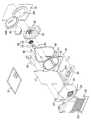
Translated fromKorean도 1은 본 발명에 따른 건조기의 실시예를 도시한 분해 사시도1 is an exploded perspective view showing an embodiment of a dryer according to the present invention
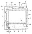
도 2는 도 1의 종단면도2 is a longitudinal cross-sectional view of FIG.
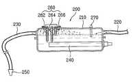
도 3은 도 1의 스팀 발생기를 도시한 단면도3 is a cross-sectional view of the steam generator of FIG.
도 4는 본 발명에 건조기의 따른 실시예를 도시한 것으로서, 스팀발생기를 중심으로 도시한 구성도Figure 4 shows an embodiment of the dryer according to the present invention, a configuration diagram showing a steam generator mainly
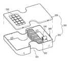
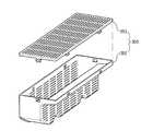
도 5는 도 4의 물공급원의 일예를 도시한 분해 사시도5 is an exploded perspective view showing an example of the water supply source of FIG.
도 6은 도 5의 연수부재를 도시한 분해 사시도6 is an exploded perspective view illustrating the softening member of FIG. 5;
도 7a 내지 도 7c는 도 5를 일부 절개하여 도시한 사시도7A to 7C are perspective views partially cut away from FIG. 5.
도 8은 도 4의 물공급원과 펌프의 연결 구조를 도시한 측면도8 is a side view showing a connection structure of the water supply source and the pump of FIG.
도 9a 및 도 9b는 물공급원의 탈착 관계를 도시한 단면도9a and 9b are cross-sectional views showing the desorption relationship of the water supply source
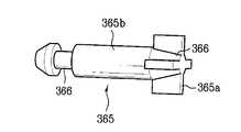
도 10는 도 9의 핀의 변형예를 도시한 사시도10 is a perspective view showing a modification of the pin of FIG.
도 11은 도 4의 물공급원과 펌프의 연결 구조의 다른 실시예를 도시한 단면도11 is a cross-sectional view showing another embodiment of the connection structure of the water supply source and the pump of FIG.
도 12는 도 4의 물공급원과 펌프의 연결 구조의 또 다른 실시예를 도시한 단면도12 is a cross-sectional view showing another embodiment of the connection structure of the water supply source and the pump of FIG.
<도면의 주요부분에 대한 부호의 설명><Description of the symbols for the main parts of the drawings>
10 : 캐비넷 20 : 드럼10: cabinet 20: drum
30 : 프런트 서포터 40 : 리어 서포터30: front supporter 40: rear supporter
50 : 린트 덕트 60 : 블로워 유닛50: lint duct 60: blower unit
70 : 모터 80 : 배기 덕트70: motor 80: exhaust duct
90 : 열풍 히터 200 : 스팀발생기90: hot air heater 200: steam generator
300 : 물공급원(카트리지) 400 : 펌프300: water supply (cartridge) 400: pump
500 : 안전밸브 250 : 노즐500: safety valve 250: nozzle
본 발명은 건조기에 관한 것으로서, 더욱 상세히는 의류 등에 생기는 주름 또는 구김 등을 제거하거나 방지할 수 있는 건조기에 관한 것이다.The present invention relates to a dryer, and more particularly, to a dryer that can remove or prevent wrinkles, wrinkles, etc. generated in clothes and the like.
건조기는 통상 세탁이 완료된 세탁물 즉 주로 의류를 고온의 공기를 이용하여 건조하는 가전 기기이다. 일반적으로 건조기는 피건조물을 수용하는 드럼, 상기 드럼을 구동하는 구동원, 상기 드럼 내부로 유입되는 공기를 가열하는 가열수단, 상기 드럼 내부의 공기를 흡입하거나 배출하는 블로워 유닛 등을 포함하여 구성된다.A dryer is a household appliance in which laundry is normally washed, that is, clothes are mainly dried using high temperature air. In general, the dryer includes a drum accommodating the object to be dried, a driving source for driving the drum, heating means for heating air introduced into the drum, and a blower unit for sucking or discharging air in the drum.
건조기는 공기를 가열하는 방식 즉 가열수단에 따라 전기식 건조기 및 가스식 건조기로 분류할 수 있다. 전기식 건조기는 공기를 전기 저항열을 이용하여 가열하며, 가스식 건조기는 공기를 가스의 연소에 의하여 발생하는 열을 이용하여 가 열한다. 건조기를 다른 방식으로 구분하면, 응축식 건조기와 배기식 건조기로 분류할 수 있다. 응축식 건조기에서는 드럼에서 피건조물과 열교환되어 다습한 상태가 된 공기가 건조기 외부로 배출되지 않고 순환되며, 별도의 응축기에서 외부 공기와 열교환시켜 응축수를 만들어 이를 외부로 배출한다. 배기식 건조기에서는 드럼에서 피건조물과 열교환되어 다습한 상태가 된 공기가 건조기의 외부로 직접 배출된다. 건조기를 또 다른 방식으로 구분하면, 피건조물을 건조기에 투입하는 방식에 따라 탑 로딩(top loading) 방식과 프런트 로딩(front loading) 방식으로 나눌 수 있다. 탑 로딩 방식에서는 피건조물이 건조기의 상측에서 투입되며, 프런트 로딩 방식에서는 피건조물이 건조기의 전면에서 투입된다. The dryer may be classified into an electric dryer and a gas dryer according to a method of heating air, that is, a heating means. The electric dryer heats air using electric resistance heat, and the gas dryer heats air using heat generated by combustion of gas. If the dryers are classified differently, they can be classified as condensation dryers and exhaust dryers. In the condenser dryer, the air that has been heat-exchanged with the dry matter in the drum is circulated without being discharged to the outside of the dryer, and in a separate condenser, heat is exchanged with the outside air to make condensate and discharged to the outside. In the exhaust dryer, the air, which has been heat exchanged with the dry matter in the drum and becomes humid, is discharged directly to the outside of the dryer. If the dryer is classified into another method, it may be divided into a top loading method and a front loading method according to a method of inputting a dry matter to the dryer. In the top loading method, the dry material is introduced from the upper side of the dryer. In the front loading method, the dry material is injected from the front of the dryer.
상술한 종래의 건조기에서는 다음과 같은 문제점이 있었다.The above-mentioned conventional dryer has the following problems.
일반적으로 건조기에는 세탁 완료되어 탈수된 세탁물이 투입되어 건조되게 된다. 그런데, 물세탁의 원리상 물세탁이 완료된 세탁물에는 구김이 발생하게 되고, 발생된 구김은 건조기에서 건조과정에서 완전히 제거되지 않는다. 따라서, 종래의 건조기에서 건조 완료된 세탁물과 같은 피건조물에 존재하는 구김을 제거하기 위하여 별도의 다림질이 필요하다는 단점이 있었다.In general, the laundry is dried and dehydrated laundry is put into the dryer to dry. However, due to the principle of water washing, wrinkles are generated in the laundry in which water washing is completed, and the generated wrinkles are not completely removed in the drying process in the dryer. Therefore, there is a disadvantage in that a separate ironing is required to remove wrinkles existing in the dry matter such as laundry which has been dried in the conventional dryer.
또한, 세탁 완료 후의 세탁물 이외에도 의류 등을 통상적으로 보관, 사용하는 경우에도 주름, 구김, 접힘 등(이하 총칭하여 "구김"이라 함)이 발생하게 된다. 이러한 의류 등의 통상적 사용, 보관에 따른 구김도 간편히 제거할 수 있는 장치의 개발이 요구되었다.In addition, wrinkles, wrinkles, folds, etc. (hereinafter collectively referred to as "wrinkles") are generated even when clothes and the like are normally stored and used in addition to laundry after washing. The development of a device that can easily remove wrinkles in accordance with the normal use, storage, such as clothing was required.
본 발명은 상술한 문제점을 해결하기 위한 것으로서, 본 발명의 목적은 의류 등에 생기는 구김을 방지 및/또는 제거할 수 있는 건조를 제공하는 것이다.SUMMARY OF THE INVENTION The present invention has been made to solve the above-mentioned problems, and an object of the present invention is to provide a drying that can prevent and / or remove wrinkles on clothing and the like.
본 발명의 다른 목적은 물공급원을 원하는 부분에 효과적이며 선택적으로 연결할 수 있는 건조기를 제공하는 것이다.Another object of the present invention is to provide a dryer which can effectively and selectively connect a water supply to a desired portion.
상술한 목적을 달성하기 위하여, 본 발명은 드럼에 고온의 열풍을 공급하기 위하여 공기를 가열하는 열풍히터와; 상기 드럼에 스팀을 공급하기 위하여 스팀을 만드는 스팀발생기와; 상기 스팀발생기에 물을 공급하며, 탈부착 가능한 물공급원과; 상기 물공급원의 물을 선택적으로 배출하며, 상기 물공급원의 내부에 위치하는 개폐부재를 포함하는 건조기를 제공한다. 상기 물공급원과 상기 스팀발생부의 사이에는 펌프가 더욱 구비되는 것이 바람직하다.In order to achieve the above object, the present invention is a hot air heater for heating the air to supply a hot air of hot air to the drum; A steam generator for producing steam to supply steam to the drum; A water supply source for supplying water to the steam generator and being detachable; It provides a dryer selectively discharges the water of the water supply source, and including an opening and closing member located inside the water supply source. It is preferable that a pump is further provided between the water supply source and the steam generator.
상기 개폐부재는 상기 물공급원의 외부와 연통하며 상기 물공급원의 내부에 위치하는 유로와, 상기 유로를 선택적으로 개폐하는 핀을 포함하여 구성되는 것이 바람직하다. 그리고, 상기 개폐부재의 유로의 내면에는 오링이 구비되는 것이 더욱 바람직하다.Preferably, the opening and closing member includes a flow passage communicating with the outside of the water supply source and positioned inside the water supply source, and a pin for selectively opening and closing the flow passage. And, it is more preferable that the O-ring is provided on the inner surface of the flow path of the opening and closing member.
상술한 본 발명에 의하면, 의류에 생기는 구김을 효과적으로 방지 및/또는 제거하는 것이 가능하며, 또한 물공급원을 원하는 부분 예를 들어 펌프의 입구측에 효과적이며 선택적으로 연결하는 것이 가능하다.According to the present invention described above, it is possible to effectively prevent and / or remove wrinkles on clothes, and also to effectively and selectively connect the water supply to a desired portion, for example, the inlet side of the pump.
이하에서는 본 발명의 구체적인 실시예를 첨부된 도면을 참조하여 상세히 설명한다.Hereinafter, with reference to the accompanying drawings a specific embodiment of the present invention will be described in detail.
이하에서는 본 발명에 따른 건조기를 설명하기 위하여, 편의상 탑 로딩 방식, 전기식, 응축식 건조기를 실시예로 들어 설명한다. 그러나, 본 발명은 이에 한정되는 것은 아니며, 프런트 로딩 방식, 가스식, 응축식 건조기 등에 적용하는 것도 물론 가능하다.Hereinafter, in order to explain the dryer according to the present invention, a tower loading method, an electric type, and a condensation type dryer will be described as examples. However, the present invention is not limited thereto, and of course, the present invention may be applied to a front loading method, a gas type, a condensation type dryer, or the like.
도 1 및 도 2를 참조하여, 본 발명에 따른 건조기의 일 실시예를 설명하면 다음과 같다.1 and 2, an embodiment of a dryer according to the present invention will be described.
건조기의 외관을 구성하는 캐비넷(10)의 내부에는 회전 가능한 드럼(20), 상기 드럼(20)을 구동시키는 모터(70) 및 벨트(68)가 설치된다. 그리고, 캐비넷(10)의 소정 위치에는 공기를 가열하여 고온의 공기(이하 "열풍"이라 함)을 만드는 히터(90)(이하 편의상 "열풍 히터"라 함), 상기 열풍 히터(90)에서 생성된 열풍을 드럼(20)에 공급하기 위한 열풍공급덕트(44)가 설치된다. 그리고, 드럼(20)에서 피건조물과 열교환된 다습한 공기를 배출하는 배기 덕트(80), 상기 다습한 공기를 빨아 들이는 블로워 유닛(60) 등도 설치된다. 한편, 캐비넷(10)의 소정 위치에는 고온의 스팀을 발생시키는 스팀발생기(200)가 설치된다. 본 실시예에서는 편의상 모터(70)와 벨트(68)를 이용하여 드럼(20)을 회전시키는 간접구동방식을 도시 및 설명하지만 본 발명은 이에 한정되지 않는다. 즉, 드럼(20)의 후면에 모터가 직결되어 드럼(20)을 직접 회전시키는 직접구동방식(Direct Drive Type)에 본 발명을 적용하는 것도 물론 가능하다.A
각각의 구성요소를 상세히 설명하면 다음과 같다.Each component will be described in detail as follows.
캐비넷(10)은 건조기의 외형을 형성하는 것으로서, 바닥면을 형성하는 베이 스(12)와, 상기 베이스(12)에서 수직으로 설치되는 한 쌍의 측면 커버(14)와, 상기 측면 커버(14)의 전면 및 후면에 각각 설치되는 프런트 커버(16) 및 리어 커버(18), 상기 측면 커버(14)의 상부에 위치하는 탑 커버(17)를 포함하여 구성된다. 각종 조작 스위치 등을 가지는 컨트롤 패널(19)은 통상 탑 커버(17) 또는 프런트 커버(16)에 위치하게 되며, 도어(164)는 프런트 커버(16)에 설치된다. 리어 커버(18)에는 외부 공기가 유입될 수 있도록 하는 흡입부(182)와, 드럼(20)의 공기가 외부로 배출되는 최종 통로인 배기홀(184)이 구비된다.The
드럼(20)의 내부 공간은 건조가 진행되는 건조 챔버 기능을 하며, 상기 드럼(20)의 내부에는 피건조물을 끌고 올라가 낙하시켜 피건조물을 뒤집어 주어 건조 효율을 높이는 리프트(22)가 설치되는 것이 바람직하다.The inner space of the
한편, 드럼(20)과 캐비넷(10)의 사이 즉, 드럼(20)과 프런트 커버(16)의 사이에는 프런트 서포터(30)가 설치되며, 드럼(20)과 리어 커버(18))의 사이에는 리어 서포터(40)가 설치된다. 프런트 서포터(30)와 리어 서포터(40)의 사이에 드럼(20)이 회전 가능하게 설치되며, 상기 프런트 서포터(30) 및 리어 서포터(40)와 드럼(20) 사이에는 각각 누설을 방지하는 실링부재(미도시)가 설치된다. 즉, 프런트 서포터(30)와 리어 서포터(40)는 상기 드럼(20)의 전면과 후면을 막아 건조 챔버를 형성하며 상기 드럼(20)의 전단과 후단을 지지하는 역할을 하게 된다.Meanwhile, the
프런트 서포터(30)에는 드럼(20)을 건조기의 외부와 연통시키는 개구부가 형성되며, 상기 개구부는 도어(164)에 의하여 선택적으로 개폐된다. 또한, 프런트 서포터(30)에는 드럼(20)의 공기가 외부로 배출되는 통로인 린트 덕트(50)가 연결되 며, 상기 린트 덕트(50)에는 린트 필터(52)가 설치된다. 상기 린트 덕트(50)에는 블로워 유닛(60)의 일측이 연결되며, 상기 블로워 유닛(60)의 타측은 배기 덕트(80)와 연결되며, 상기 배기 덕트(80)는 리어 커버(18)에 구비되는 배기홀(184)과 연통된다. 따라서, 블로워 유닛(60)이 작동하면, 드럼(20) 내부의 공기는 린트 덕트(50), 배기 덕트(80), 배기홀(184)을 통하여 외부로 배출된다. 이 때 보푸라기 등의 이물질은 린트 필터(52)에서 여과되게 된다. 통상 상기 블로워 유닛(60)은 블로워(62)와 블로워 하우징(64)으로 구성되며, 상기 블로워(64)는 드럼(20)을 구동시키는 모터(70)에 연결되어 구동되는 것이 일반적이다.The
리어 서포터(40)에는 통상 다수의 통공으로 구성되는 개구부(42)가 형성되며, 상기 개구부(42)에 열풍공급덕트(44)가 연결된다. 상기 열풍공급덕트(44)는 드럼(20)과 연통하여 상기 드럼(20)에 열풍을 공급하는 통로의 역할을 한다. 따라서, 상기 열풍공급덕트(44)의 소정 위치에는 열풍 히터(90)가 설치된다.The
한편, 캐비넷(10)의 소정 위치에는 스팀을 발생시켜 드럼(20)의 내부로 공급하는 스팀발생기(200)가 설치된다. 도 3을 참조하여, 스팀발생기(200)에 대하여 상세히 설명하면 다음과 같다.Meanwhile, a
스팀발생기(200)는 내부에 물이 수용되는 워터 탱크(210)와, 상기 워터 탱크(210) 내부에 장착되는 히터(240)와, 상기 스팀발생기(200)의 수위를 측정하는 수위센서(260)와, 상기 스팀발생기(200)의 온도를 측정하는 온도센서(270)를 포함하여 구성된다. 수위센서(260)은 통상 공통전극(262), 저수위전극(264) 및 고수위전극(266)으로 구성되어, 공통전극(262)과 고수위전극(264)의 통전 또는 공통전 극(262)과 저수위전극(266)의 통전 여부에 의하여 고수위 및 저수위를 감지한다.The
스팀발생기(200)의 일측에는 물을 공급하는 급수 호스(220)가 연결되며, 타측에는 스팀을 배출하는 스팀 호스(230)가 연결되며, 상기 스팀 호스(230)의 선단에는 소정 형상의 노즐(250)이 구비되는 것이 바람직하다. 통상, 급수 호스(220)의 일단은 수도꼭지와 같은 외부 물 공급원과 연결되며, 스팀 호스(230)의 선단부 또는 노즐(25) 즉 스팀 토출구는 드럼(20)의 소정 위치에 위치되어, 드럼(20)의 내부로 스팀을 분사하게 된다.One side of the
한편, 본 실시예에서는 소정 크기의 워터 탱크(210)에 수용된 일정량의 물을 히터(240)로 가열하여 스팀을 발생시키는 방식의 스팀발생기(200)(이하 편의상 "통가열 방식"이라 함)를 도시 및 설명하였으나, 본 발명은 이에 한정되지 않는다. 즉, 본 발명에서는 스팀을 발생할 수 있는 장치이면 어떠한 것이라도 스팀발생기로 사용할 수 있다. 예를 들어, 물이 통과하는 급수 호스의 둘레에 직접 히터를 설치하여 즉 물을 소정 공간에 수용하지 않고 가열하는 방식(이하 편의상 "관가열 방식"이라 함)도 사용하는 것이 가능하다.Meanwhile, in the present embodiment, the steam generator 200 (hereinafter, referred to as a "heating heating method") of a method of generating steam by heating a predetermined amount of water contained in the
도 4를 참조하여, 본 발명에 따른 건조기의 다른 실시예를 설명하면 다음과 같다.Referring to Figure 4, another embodiment of the dryer according to the present invention will be described.
본 실시예에서는, 스팀발생기(200)에 물을 공급하는 물공급원이 탈부착 가능하다. 상술한 실시예에서와 같이, 물공급원이 수도꼭지일 수도 있지만, 이런 경우에는 설치가 복잡하다. 왜냐하면, 건조기에서는 통상 물을 사용하지 않으므로 수도꼭지를 물공급원으로 사용하는 경우에는 이에 부대하하는 각종 장치 등이 추가로 설치하는 것이 필요하기 때문이다. 따라서, 본 실시예에서와 같이, 탈부착 가능한 물공급원(Detachable Water Supply Source)(300)을 사용하여, 상기 물공급원(300)을 분리하여 물을 공급하고, 물을 채운 물공급원(300)을 스팀발생기(200)의 물공급 유로 즉 급수 호스(220)에 연결하면 대단히 편리하다.In this embodiment, the water supply source for supplying water to the
그리고, 상기 물공급원(300)과 상기 스팀발생기(200)의 사이에는 펌프(400)가 구비되는 것이 바람직하다. 상기 펌프(400)는 정역회전 가능하여, 스팀발생기(200)로 물 공급 및 필요에 따라 스팀발생기(200)의 잔수를 회수하는 것이 가능한 것이 보다 바람직하다. 펌프(400)를 사용하지 않고 물공급원(300)과 스팀발생기(200) 사이의 수주차를 이용하여 상기 스팀발생기(200)에 물을 공급하는 것도 가능하다. 그러나, 통상 건조기의 각종 부품 등은 규격품이며 콤팩트하게 설계되므로 구조적 공간의 절대로 부족하다. 따라서, 종래의 건조기의 각종 부품의 크기를 변경하기 않으면 수주차를 이용한 급수가 사실상 불가능하다. 따라서, 소형의 펌프(400)를 사용하면, 종래의 건조기의 각종 부픔의 크기를 변경하기 않고도 스팀발생기(200) 등을 설치할 수 있으므로 펌프(400)를 이용하는 것이 대단히 유용하다. 그리고, 스팀발생기(200)의 잔수를 회수하는 이유는 스팀발생기(200)를 오랫동안 사용하지 않으면 잔수에 의하여 히터가 손상되거나, 차후에 부패한 물이 사용될 우려가 있기 때문이다.In addition, the
그리고, 상술한 실시예에서는 스팀발생기(200)의 상부에서 물이 공급 및 스팀 배출이 발생하였지만, 본 실시예에서는 상기 스팀발생기(200)의 하부에 물이 공급되며, 상기 스팀발생기(200)의 상부에서 스팀이 배출되는 것이 바람직하다. 이렇 게 구성하는 것이 스팀발생기(200)의 잔수를 회수하는데에 유리하다.In addition, in the above-described embodiment, water is supplied and steam is discharged from the upper portion of the
또한, 상기 스팀발생기(200)에서 스팀을 배출하는 스팀 유로 즉 스팀 호스(230)에는 안전밸브(500)가 구비되는 것이 바람직하다.In addition, it is preferable that the
각각의 구성요소를 상세히 설명한다.Each component is described in detail.
먼저, 도 5를 참조하여 탈부착 가능한 물공급원(300)(이하 편의상 "카트리지"라 함)을 상세히 설명한다.First, the detachable water supply source 300 (hereinafter referred to as "cartridge" for convenience) will be described in detail with reference to FIG. 5.
카트리지(300)는 실질적으로 물을 수용하는 하부 하우징(310)과, 상기 하부 하우징(310)에 탈부착 가능한 상부 하우징(320)을 포함하여 구성된다. 카트리지(300)를 하부 하우징(310) 및 상부 하우징(320)으로 구성하면, 카트리지(300) 내부에 쌓인 물때 등을 청소하기가 용이하며, 필터(330, 340) 및 연수부재(350) 등을 분리하여 청소 또는 재생하는 것이 용이하기 때문이다.The
상부 하우징(320)에는 제1필터(330)가 설치되는 것이 바람직하다. 즉, 상부 하우징(320)의 물 유입부에 제1필터(330)가 설치되어, 카트리지(300)로 물을 공급할 때 1차적으로 물을 여과하는 것이 바람직하다.It is preferable that the
하부 하우징(310)에는 상기 카트리지(300)의 물을 외부로 선택적으로 공급하는 개폐부재(360)가 구비되어, 상기 카트리지(300)가 분리된 경우에는 상기 카트리지(300)의 물이 외부로 배출되지 않으며, 상기 카트리지(300)가 설치된 경우에는 상기 카트리지(300)의 물이 외부로 배출되게 하는 것이 바람직하다. 그리고, 상기 개폐부재(360)에는 물을 여과하는 제2필터(340)가 연결되는 것이 바람직하며, 상기 제2필터(340)는 탈부착 가능한 것이 더욱 바람직하다. 제1필터(330) 및 제2필 터(340)를 이용하여, 미세먼지와 같은 물에 섞여 있는 불순물을 2중으로 여과할 수 있다. 제1필터(330)는 약 50 메쉬망(mesh net), 제2필터(340)는 약 60메쉬망을 사용하는 것이 바람직하다. 여기서, 50 메쉬망은 일정 면적당 메쉬의 개수가 50개인 것을 의미하여, 따라서 제1필터(330)의 메쉬의 구성하는 기공의 크기가 제2필터(340)의 기공의 크기보다 커서, 큰 이물질을 제1필터(330)에서 1차적으로 여과하고, 작은 이물질은 제2필터(340)에서 여과하게 된다.The
또한, 카트리지(300)의 내부에는 물을 연수화하는 연수부재(350)가 더욱 구비되는 것이 바람직하다. 그리고, 상기 연수부재(350)는 탈부착 가능한 것이 더욱 바람직하다. 도 6에 도시한 바와 같이, 연수부재(350)는 다수의 통공이 형성되는 하부 하우징(352)과, 상기 하부 하우징(352)에 탈부착 가능하며 다수의 통공이 형성되는 상부 하우징(353)를 포함하여 구성되며, 상기 상부 하우징(353) 및 하부 하우징(352)에 의하여 정의되는 공간에 충진되는 이온교환수지(미도시)를 포함하는 것이 바람직하다.In addition, the inside of the
연수부재(350)를 사용하는 이유는 다음과 같다. 스팀발생기(200)에 공급되는 물이 경도가 높은 경우에는, 물에 녹아 있는 탄산수소칼슘(Ca(HCO3)2)이 가열되면 석회(탄산칼슘(CaCO3) 등)가 석출되게 되고, 석회에 의하여 히터의 부식 등을 유발할 수 있다. 특히, 유럽 및 미주 지역이 물은 경도가 높은 연수이므로 이러한 현상이 심할 수 있다. 따라서, 이온교환수지를 이용하여, 칼슘, 마그네슘이온 등을 미리 제거하여, 석회의 석출을 방지하는 것이 바람직하다. 그리고, 이온교환수지는 연수를 진행함에 따라서 성능이 저하되므로, 재생제 예를 들어 석회분해 물질인 소금(NaCl)으로 재생시켜 재사용하는 것이 가능하다. 참고로, 이온교환수지에 의한 연수화 과정은 2(R-SONa) + Ca2 <-> (R-SO)Ca + 2Na 이며, 재생 과정은 (R-SO)Ca + 2NaCl <-> 2(R-SONa) + CaCl 이다.The reason for using the softening
도 7a 내지 도 7c를 참조하여, 제2필터(340)와 개폐부재(360)의 탈부착 구조를 상세히 설명하면 다음과 같다.7A to 7C, the detachable structure of the
카트리지(300)의 하부 하우징(310)에는 상기 카트리지(300)와 연통하는 개폐부재(360)가 구비된다. 개폐부재(360)는 카트리지(300)와 연통하는 유로(362)와, 상기 유로(362)를 선택적으로 개폐하는 핀(365)을 포함하여 구성된다. 상기 유로(362)는 내측 유로(362a)와 외측 유로(362b)로 구성되며, 내측 유로(362a)의 외면에는 걸림돌기(361)가 형성된다. 그리고, 제2필터(340)는 상기 내측 유로(362a)에 대응하는 형상을 가지는 케이스(341)와, 상기 케이스(341)의 일측에 구비되는 필터링부(344)를 포함하여 구성된다. 그리고, 상기 케이스(341)의 일측에는 상기 내측 유로(362a)의 걸림돌기(361)에 대응하는 홈부(342)가 형성된다. 상기 홈부(342)는 대략 "L"형상 즉 수평부와 수직부를 가진다. 따라서, 도 7b에 도시한 바와 같이, 제2필터(340)의 홈부(342) 정확히는 수평부를 내측 유로(362a)의 걸림돌기(361) 방향으로 넣은 후에, 도 7c에 도시한 바와 같이, 상기 제2필터(340)를 돌리면 상기 제2필터(340)와 개폐부재(360)와의 결합이 완료된다. 제2필터(340)를 분리하는 것을 이에 반대이므로, 상세한 설명은 생략한다.The
도 8을 참조하여, 카트리지(300)와 펌프(400) 사이의 연결 관계를 상세히 설 명한다.Referring to FIG. 8, the connection relationship between the
도 8에 도시한 바와 같이, 카트리지(300)와 펌프(400)는 중간 호스(490)를 매개로 연결된다. 다만, 중간 호스(490)의 일측은 펌프(400)의 인입구(430)에 직결되지만, 중간 호스(490)의 타측은 접속구(480)를 매개로 카트리지(300)와 연결된다. 펌프(400)의 인입구(430)/접속구(480)와 중간 호스(490)는 클램프(492)에 의하여 누설이 방지되게 하는 것이 바람직하다.As shown in FIG. 8, the
도 9 및 도 10을 참조하여, 카트리지(300)와 접속구(480)의 연결 관계를 상세히 설명한다.9 and 10, the connection relationship between the
상술한 바와 같이, 카트리지(300)에는 상기 카트리지(300)와 연통하는 개폐부재(360)가 구비된다. 개폐부재(360)는 유로(362)와, 상기 유로(362)를 선택적으로 개폐하는 핀(365)을 포함하여 구성된다. 상기 유로(362)는 내측 유로(362a)와 외측 유로(362b)로 구성되며, 상기 외측 유로(362b)의 외면에는 기밀을 위하여 오링(O-ring)(369)이 구비된다.As described above, the
한편, 핀(365)의 몸통부(365b)의 일측에는 오목부(366)가 구비되며, 타측에는 유동부(365a)가 구비된다.(도 10 참조) 상기 오목부(366)에는 개폐부(367)가 설치되며, 상기 유동부(365a)는 대략 십자형으로 구성되어 상기 십자날개의 사이로 물이 흐르게 된다. 상기 개폐부(367)는 고무 재질인 것이 바람직하다.On the other hand, one side of the body portion (365b) of the pin (365) is provided with a
유로(362)를 설명하면, 유로의 내부에는 핀(365)의 몸통부(365b)를 지지하며 다수의 통공(363a)이 형성되는 지지부(363)가 구비되며, 상기 지지부(363) 및 핀(365)의 유동부(365a)의 사이에는 스프링(364)이 구비된다. 그리고, 접속구(480) 는 개폐부재(360)의 외측 유로(362b)의 외경보다 큰 내경을 가지는 외측부(482)와, 상기 외측 유로(362b)의 내경보다 작은 외경을 가지는 내측부(484)로 구성된다.Referring to the
도 9a에 도시한 바와 같이, 카트리지(300)가 접속구(480)에서 분리된 상태에서는, 스프링(364)에 의하여 핀(365)의 일측에 설치된 개폐부(367)가 내측 유로(362a)의 선단을 막은 상태가 된다. 따라서, 카트리지(300)의 물이 유로를 통하여 외부로 유출되지 않는다. 그러나, 도 9b에 도시한 바와 같이, 카트리지(300)를 접속구(480)에 끼우면 접속구(480)의 내측부(484)에 의하여 핀(365)이 스프링(364)의 탄성력을 이기고 내측 유로(362a) 방향으로 전진하게 된다. 따라서, 핀(365)의 일측에 설치된 개폐부(367)가 내측 유로(362a)의 선단에서 분리되어 그 틈으로 물이 흐르게 되어, 카트리지(300)의 물이 유로를 통하여 외부로 즉 펌프(400) 방향으로 유출되게 된다. 그리고, 본 발명에서는 스프링(364) 및 오링(369)을 이용한 2중 실링 구조이므로 물의 누설을 효과적으로 방지할 수 있다.As shown in FIG. 9A, in the state where the
그리고, 도 10에 도시한 바와 같이, 상기 핀(365)의 일단 즉 유동부(365a)의 내부(365)는 테이퍼지는 것이 바람직하다. 이렇게 구성하면, 단순 원통형에 비하여, 물의 유동하는 통로의 면적이 커지므로 물이 더욱 효과적으로 유동할 수 있다.As shown in FIG. 10, it is preferable that one end of the
한편, 도 11에 도시한 바와 같이, 중간 호스(490)를 사용하지 않고 카트리지(300)를 펌프(400)에 직결하는 것도 가능하다. 이때에는 펌프(400)의 인입구(430a)의 형상을 적절히 변경 즉 외측부(432)와 내측부(434)로 구성하여야 한다. 즉, 펌프(400)의 인입구(430a)의 형상을 도 9의 접속구(480)와 유사하게 구성한다. 도 8 및 도 9에 도시한 연결 구조에 비하여, 이렇게 구성하면 중간 호스(490), 실 링을 위한 클램프(492) 등을 생략할 수 있으므로, 재료비 및 공수를 절감할 수 있다는 이점이 있다.On the other hand, as shown in FIG. 11, it is also possible to connect the
한편, 상술한 실시예에서는 제1필터(330), 제2필터(340) 및 연수부재(350)가 탈부착 가능한 카트리지(300)에 설치되는 것을 도시 및 설명하였으나, 본 발명은 이에 한정되지 않는다. 예를 들어, 물공급원(300)으로 외부 꼭지가 사용되는 경우에도 적용 가능하다. 이러한 경우에는 스팀발생기(200)로 연결되는 급수 유로 상에 제1필터(330), 제2필터(340) 및 연수부재(350) 중의 최소한 한 개를 설치하는 것이 바람직하며, 이 경우에도 제1필터(330), 제2필터(340) 및 연수부재(350)룰 탈부착 가능하게 설치하는 것이 더욱 바람직하다. 그리고, 제1필터(330), 제2필터(340) 및 연수부재(350)를 하나의 용기에 구비하여, 상기 용기 자체도 급수 유로에서 탈부착 가능하게 설치하는 것이 바람직하다.Meanwhile, in the above-described embodiment, although the
한편, 상술한 실시예에서는 개폐부재(360)의 유로(362)의 일단 즉 외측 유로(362b)가 카트리지(300)의 외부로 돌출하게 되어, 상기 카트리지(300)가 전체적으로 길어지게 된다. 따라서, 카트리지(300)를 사출하는 경우에 뒤틀림이 발생할 우려가 있으며, 상기 카트리지(300)의 탈부착시 돌출된 부위가 부딪쳐 파손될 우려가 있다. 이를 개선하기 위한 구조를 도 12를 참조하여 설명하면 다음과 같다.On the other hand, in the above-described embodiment, one end of the
도 12에 도시한 구조도 도 11에 도시한 구조와 원리는 유사하다. 다만, 본 실시예에서는 물공급원(카트리지)(300)의 물을 선택적으로 배출하도록 하는 개폐부재(360)가 상기 카트리지(300)의 내부에 위치한다. 즉, 상술한 실시예와 마찬가지로, 본 실시예의 개페부재(360)도 외부와 연통하는 유로(362)와 상기 유로(362)를 선택적으로 개폐하는 개폐부(365)로 구성되지만, 상기 유로(362)가 전부 상기 카트리지(300)의 내부에 위치한다. 그리고, 개폐부재(360)의 유로(362)의 내면에는 오링(369a)이 구비된다. 물론 오링(369a)은 연결부(434, 484)의 외면에 형성될 수도 있다.Structure diagram shown in FIG. 12 The structure and principle shown in FIG. 11 are similar. However, in the present embodiment, the opening and closing
유로(362)가 카트리지(300)의 내부에 위치하는 경우에는, 중간 호스 및 펌프의 인입구와 같은 상기 유로(362)에 연결되는 부위가 내측부와 외측부(도 9의 482, 도 11의 432)를 가지는 이중구조가 아니어도 된다. 왜냐하면, 유로(362)가 외측부의 역할을 겸할 수 있기 때문이다.When the
따라서, 본 실시예에 의하면, 개폐부재(360)가 카트리지(300)의 외부로 돌출하지 않기 때문에 카트리지(300)의 제작의 편의성을 향상시키고 파손 위험을 줄일 수 있다.Therefore, according to the present embodiment, since the opening and closing
본 발명자의 실험 결과에 의하면, 의류의 종류 예를 들어 옷감의 종류, 흡습의 정도에 따라 차이가 있지만, 본 발명에 의하면 구김 제거 및 방지 효과가 있었다. 그리고, 피건조물의 일 예로써 세탁기에서 탈수 완료된 세탁물도 가능하지만, 이에 한정되지 않는다. 예를 들어, 하루 정도 입은 의류 즉 이미 건조된 상태이며 구김이 적은 의류를 본 발명에 의한 건조기에서 구김을 제거할 수 있으면, 이러한 경우에 특히 유용할 수 있다. 즉, 일종의 구김제거장치로 본 발명에 따른 건조기를 사용하는 것도 가능하다.According to the experimental results of the present inventors, although there are differences depending on the type of clothes, for example, the type of cloth and the degree of moisture absorption, the present invention has the effect of removing wrinkles and preventing them. The laundry dehydrated in the washing machine may be used as an example of the object to be dried, but is not limited thereto. For example, clothing that is worn for about a day, that is, clothes that are already dried and less wrinkled, can be particularly useful in this case if it is possible to remove wrinkles in the dryer according to the present invention. That is, it is also possible to use the dryer according to the present invention as a kind of wrinkle removal device.
상술한 본 발명에 따른 건조기 및 그 제어방법의 효과를 설명하면 다음과 같 다.Referring to the effect of the dryer and the control method according to the invention described above are as follows.
첫째, 본 발명에 따르면, 건조 완료된 피건조물에 구김 또는 주름이 생기는 것을 효과적으로 방지 또는 제거할 수 있다는 이점이 있다. 또한, 본 발명에 따르면, 피건조물의 살균 및 냄세 제거를 할 수 있다는 이점도 있다.First, according to the present invention, there is an advantage that can effectively prevent or eliminate the occurrence of wrinkles or wrinkles in the dried product to be dried. Moreover, according to this invention, there also exists an advantage that sterilization and smell removal of a to-be-dried thing can be performed.
둘째, 본 발명에 따르면, 건조된 상태의 의류에 있는 구김 또는 주름도 별도의 다림질없이도 효과적으로 제거할 수 있다는 이점이 있다.Second, according to the present invention, there is an advantage that wrinkles or wrinkles in the clothes in a dry state can be effectively removed without additional ironing.
셋째, 본 발명에 따르면, 카트리지를 선택적으로 개페하는 개폐부재가 카트리지의 외부로 돌출하지 않기 때문에 카트리지의 제작의 편의성을 향상시키고 파손 위험을 줄일 수 있다.Third, according to the present invention, since the opening and closing member for selectively opening and closing the cartridge does not protrude to the outside of the cartridge, the convenience of manufacture of the cartridge can be improved and the risk of breakage can be reduced.
Claims (4)
Translated fromKoreanPriority Applications (1)
| Application Number | Priority Date | Filing Date | Title |
|---|---|---|---|
| KR1020060095019AKR100774219B1 (en) | 2006-09-28 | 2006-09-28 | dryer |
Applications Claiming Priority (1)
| Application Number | Priority Date | Filing Date | Title |
|---|---|---|---|
| KR1020060095019AKR100774219B1 (en) | 2006-09-28 | 2006-09-28 | dryer |
Publications (1)
| Publication Number | Publication Date |
|---|---|
| KR100774219B1true KR100774219B1 (en) | 2007-11-08 |
Family
ID=39061140
Family Applications (1)
| Application Number | Title | Priority Date | Filing Date |
|---|---|---|---|
| KR1020060095019AExpired - Fee RelatedKR100774219B1 (en) | 2006-09-28 | 2006-09-28 | dryer |
Country Status (1)
| Country | Link |
|---|---|
| KR (1) | KR100774219B1 (en) |
Cited By (6)
| Publication number | Priority date | Publication date | Assignee | Title |
|---|---|---|---|---|
| KR100845872B1 (en) | 2007-04-25 | 2008-07-14 | 엘지전자 주식회사 | Steam dryer |
| KR100857802B1 (en) | 2007-05-09 | 2008-09-09 | 엘지전자 주식회사 | Steam dryer |
| US8127576B2 (en) | 2007-05-09 | 2012-03-06 | Lg Electronics Inc. | Laundry machine |
| KR101253180B1 (en) | 2006-12-15 | 2013-04-10 | 엘지전자 주식회사 | Steam laundry dryer |
| CN113389030A (en)* | 2021-07-16 | 2021-09-14 | 珠海格力电器股份有限公司 | Hanging ironing machine |
| JP2023053284A (en)* | 2021-02-18 | 2023-04-12 | パナソニックIpマネジメント株式会社 | washing machine |
Citations (1)
| Publication number | Priority date | Publication date | Assignee | Title |
|---|---|---|---|---|
| KR100698132B1 (en) | 2006-06-12 | 2007-03-26 | 엘지전자 주식회사 | dryer |
- 2006
- 2006-09-28KRKR1020060095019Apatent/KR100774219B1/ennot_activeExpired - Fee Related
Patent Citations (1)
| Publication number | Priority date | Publication date | Assignee | Title |
|---|---|---|---|---|
| KR100698132B1 (en) | 2006-06-12 | 2007-03-26 | 엘지전자 주식회사 | dryer |
Cited By (6)
| Publication number | Priority date | Publication date | Assignee | Title |
|---|---|---|---|---|
| KR101253180B1 (en) | 2006-12-15 | 2013-04-10 | 엘지전자 주식회사 | Steam laundry dryer |
| KR100845872B1 (en) | 2007-04-25 | 2008-07-14 | 엘지전자 주식회사 | Steam dryer |
| KR100857802B1 (en) | 2007-05-09 | 2008-09-09 | 엘지전자 주식회사 | Steam dryer |
| US8127576B2 (en) | 2007-05-09 | 2012-03-06 | Lg Electronics Inc. | Laundry machine |
| JP2023053284A (en)* | 2021-02-18 | 2023-04-12 | パナソニックIpマネジメント株式会社 | washing machine |
| CN113389030A (en)* | 2021-07-16 | 2021-09-14 | 珠海格力电器股份有限公司 | Hanging ironing machine |
Similar Documents
| Publication | Publication Date | Title |
|---|---|---|
| KR101341461B1 (en) | Steam laundry dryer | |
| KR100698132B1 (en) | dryer | |
| KR100830514B1 (en) | Dryer and its control method | |
| KR101253180B1 (en) | Steam laundry dryer | |
| US20090307921A1 (en) | Laundry dryer and method for controlling the same | |
| KR100735707B1 (en) | Dryer and its control method | |
| US20080141558A1 (en) | Laundry machine | |
| KR100921459B1 (en) | Steam dryer | |
| KR20080025519A (en) | dryer | |
| KR100774219B1 (en) | dryer | |
| KR100698133B1 (en) | Dryer Control Method | |
| KR101265615B1 (en) | Laundry treating apparatus | |
| KR101341463B1 (en) | Steam laundry dryer | |
| KR100755863B1 (en) | Dryer and its control method | |
| KR100698134B1 (en) | Dryer and its control method | |
| KR101387474B1 (en) | Steam laundry dryer | |
| KR101341460B1 (en) | Steam laundry dryer | |
| KR100698224B1 (en) | dryer | |
| KR101341464B1 (en) | Steam laundry dryer | |
| KR101342366B1 (en) | Steam laundry dryer | |
| KR100698222B1 (en) | Dryer and its control method | |
| KR20080029336A (en) | Dryer and its control method | |
| KR100813056B1 (en) | Dryer and its control method | |
| KR100698223B1 (en) | Dryer and its control method | |
| KR100833864B1 (en) | Steam dryer |
Legal Events
| Date | Code | Title | Description |
|---|---|---|---|
| A201 | Request for examination | ||
| PA0109 | Patent application | St.27 status event code:A-0-1-A10-A12-nap-PA0109 | |
| PA0201 | Request for examination | St.27 status event code:A-1-2-D10-D11-exm-PA0201 | |
| E902 | Notification of reason for refusal | ||
| PE0902 | Notice of grounds for rejection | St.27 status event code:A-1-2-D10-D21-exm-PE0902 | |
| P11-X000 | Amendment of application requested | St.27 status event code:A-2-2-P10-P11-nap-X000 | |
| P13-X000 | Application amended | St.27 status event code:A-2-2-P10-P13-nap-X000 | |
| E701 | Decision to grant or registration of patent right | ||
| PE0701 | Decision of registration | St.27 status event code:A-1-2-D10-D22-exm-PE0701 | |
| GRNT | Written decision to grant | ||
| PR0701 | Registration of establishment | St.27 status event code:A-2-4-F10-F11-exm-PR0701 | |
| PR1002 | Payment of registration fee | St.27 status event code:A-2-2-U10-U11-oth-PR1002 Fee payment year number:1 | |
| PG1601 | Publication of registration | St.27 status event code:A-4-4-Q10-Q13-nap-PG1601 | |
| G170 | Re-publication after modification of scope of protection [patent] | ||
| PG1701 | Publication of correction | St.27 status event code:A-5-5-P10-P19-oth-PG1701 Patent document republication publication date:20080415 Republication note text:Request for Correction Notice (Document Request) Gazette number:1007742190000 Gazette reference publication date:20071108 | |
| PN2301 | Change of applicant | St.27 status event code:A-5-5-R10-R13-asn-PN2301 St.27 status event code:A-5-5-R10-R11-asn-PN2301 | |
| R18-X000 | Changes to party contact information recorded | St.27 status event code:A-5-5-R10-R18-oth-X000 | |
| R18-X000 | Changes to party contact information recorded | St.27 status event code:A-5-5-R10-R18-oth-X000 | |
| PR1001 | Payment of annual fee | St.27 status event code:A-4-4-U10-U11-oth-PR1001 Fee payment year number:4 | |
| PR1001 | Payment of annual fee | St.27 status event code:A-4-4-U10-U11-oth-PR1001 Fee payment year number:5 | |
| FPAY | Annual fee payment | Payment date:20121026 Year of fee payment:6 | |
| PR1001 | Payment of annual fee | St.27 status event code:A-4-4-U10-U11-oth-PR1001 Fee payment year number:6 | |
| FPAY | Annual fee payment | Payment date:20131024 Year of fee payment:7 | |
| PR1001 | Payment of annual fee | St.27 status event code:A-4-4-U10-U11-oth-PR1001 Fee payment year number:7 | |
| FPAY | Annual fee payment | Payment date:20141024 Year of fee payment:8 | |
| PR1001 | Payment of annual fee | St.27 status event code:A-4-4-U10-U11-oth-PR1001 Fee payment year number:8 | |
| PN2301 | Change of applicant | St.27 status event code:A-5-5-R10-R13-asn-PN2301 St.27 status event code:A-5-5-R10-R11-asn-PN2301 | |
| FPAY | Annual fee payment | Payment date:20151023 Year of fee payment:9 | |
| PR1001 | Payment of annual fee | St.27 status event code:A-4-4-U10-U11-oth-PR1001 Fee payment year number:9 | |
| PR1001 | Payment of annual fee | St.27 status event code:A-4-4-U10-U11-oth-PR1001 Fee payment year number:10 | |
| P22-X000 | Classification modified | St.27 status event code:A-4-4-P10-P22-nap-X000 | |
| PR1001 | Payment of annual fee | St.27 status event code:A-4-4-U10-U11-oth-PR1001 Fee payment year number:11 | |
| PR1001 | Payment of annual fee | St.27 status event code:A-4-4-U10-U11-oth-PR1001 Fee payment year number:12 | |
| PR1001 | Payment of annual fee | St.27 status event code:A-4-4-U10-U11-oth-PR1001 Fee payment year number:13 | |
| PN2301 | Change of applicant | St.27 status event code:A-5-5-R10-R13-asn-PN2301 St.27 status event code:A-5-5-R10-R11-asn-PN2301 | |
| PR1001 | Payment of annual fee | St.27 status event code:A-4-4-U10-U11-oth-PR1001 Fee payment year number:14 | |
| PR1001 | Payment of annual fee | St.27 status event code:A-4-4-U10-U11-oth-PR1001 Fee payment year number:15 | |
| P22-X000 | Classification modified | St.27 status event code:A-4-4-P10-P22-nap-X000 | |
| PR1001 | Payment of annual fee | St.27 status event code:A-4-4-U10-U11-oth-PR1001 Fee payment year number:16 | |
| PC1903 | Unpaid annual fee | St.27 status event code:A-4-4-U10-U13-oth-PC1903 Not in force date:20231102 Payment event data comment text:Termination Category : DEFAULT_OF_REGISTRATION_FEE | |
| P22-X000 | Classification modified | St.27 status event code:A-4-4-P10-P22-nap-X000 | |
| PC1903 | Unpaid annual fee | St.27 status event code:N-4-6-H10-H13-oth-PC1903 Ip right cessation event data comment text:Termination Category : DEFAULT_OF_REGISTRATION_FEE Not in force date:20231102 |