KR100773817B1 - RFID tag and RFID system having same - Google Patents
RFID tag and RFID system having sameDownload PDFInfo
- Publication number
- KR100773817B1 KR100773817B1KR1020060023975AKR20060023975AKR100773817B1KR 100773817 B1KR100773817 B1KR 100773817B1KR 1020060023975 AKR1020060023975 AKR 1020060023975AKR 20060023975 AKR20060023975 AKR 20060023975AKR 100773817 B1KR100773817 B1KR 100773817B1
- Authority
- KR
- South Korea
- Prior art keywords
- directional antenna
- rfid
- rfid tag
- antenna
- reflector
- Prior art date
- Legal status (The legal status is an assumption and is not a legal conclusion. Google has not performed a legal analysis and makes no representation as to the accuracy of the status listed.)
- Expired - Fee Related
Links
Images


Classifications
- E—FIXED CONSTRUCTIONS
- E04—BUILDING
- E04H—BUILDINGS OR LIKE STRUCTURES FOR PARTICULAR PURPOSES; SWIMMING OR SPLASH BATHS OR POOLS; MASTS; FENCING; TENTS OR CANOPIES, IN GENERAL
- E04H17/00—Fencing, e.g. fences, enclosures, corrals
- E04H17/14—Fences constructed of rigid elements, e.g. with additional wire fillings or with posts
- E04H17/1413—Post-and-rail fences, e.g. without vertical cross-members
- E04H17/1447—Details of connections between rails and posts
- E04H17/1465—Details of connections between rails and posts the rails being supported within blind or through holes of the posts
- E—FIXED CONSTRUCTIONS
- E04—BUILDING
- E04H—BUILDINGS OR LIKE STRUCTURES FOR PARTICULAR PURPOSES; SWIMMING OR SPLASH BATHS OR POOLS; MASTS; FENCING; TENTS OR CANOPIES, IN GENERAL
- E04H17/00—Fencing, e.g. fences, enclosures, corrals
- E04H17/14—Fences constructed of rigid elements, e.g. with additional wire fillings or with posts
- E04H17/20—Posts therefor
Landscapes
- Engineering & Computer Science (AREA)
- Architecture (AREA)
- Civil Engineering (AREA)
- Structural Engineering (AREA)
- Aerials With Secondary Devices (AREA)
- Details Of Aerials (AREA)
Abstract
Translated fromKoreanDescription
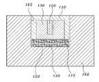
Translated fromKorean도 1a 및 도 1b는 본 발명의 일 실시예에 따른 RFID 태그의 구성을 나타낸 분해 사시도와 그 단면도이다.1A and 1B are exploded perspective views and cross-sectional views illustrating a configuration of an RFID tag according to an embodiment of the present invention.
도 2는 도 1a 및 도 1b의 RFID 태그에 구비되는 다이폴 안테나의 지향성에 대한 설명도이다.FIG. 2 is an explanatory diagram illustrating the directivity of the dipole antenna included in the RFID tag of FIGS. 1A and 1B.
도 3은 도 1a 및 도 1b의 RFID 태그가 구비된 RFID 시스템의 구성을 개략적으로 나타낸 설명도이다.3 is an explanatory diagram schematically showing the configuration of an RFID system with an RFID tag of FIGS. 1A and 1B.
<도면의 주요 부분에 관한 부호의 설명><Explanation of symbols on main parts of the drawings>
110 : 상부 케이스115 : 하부 케이스110: upper case 115: lower case
120 : 안테나122 : IC 칩120: antenna 122: IC chip
124 : 지지체130 : 스페이서124
140 : 반사판150 : 고정 수단140: reflector 150: fixing means
310 : 태그320 : 판독기310: Tag 320: Reader
322 : 외부 안테나324 : 송수신기322: external antenna 324: transceiver
326 : 제어부330 : 서버326: control unit 330: server
본 발명은 RFID(Radio Frequency IDentification) 태그 및 이를 구비하는 RFID 시스템에 관한 것으로, 더욱 상세하게는, 크기 및 제조 비용 등의 증가없이 최대 감지거리를 향상시킬 수 있도록 개량된 RFID 태그와 이를 구비하는 RFID 시스템에 관한 것이다.The present invention relates to an RFID (Radio Frequency IDentification) tag and an RFID system having the same. More particularly, the RFID tag and the RFID including the improved RFID tag can be improved to improve the maximum sensing distance without increasing the size and manufacturing cost. It's about the system.
RFID 시스템은 각종 물품에 소형 칩 등을 부착해 사물의 정보와 주변 환경정보를 무선 전파에 의해 전송 처리하는 비접촉식 인식 시스템으로, DSRC(dedicated short range communication: 전용 근거리 통신) 또는 무선 식별 시스템이라고도 한다.The RFID system is a non-contact recognition system that attaches a small chip to various items and transmits and processes information of an object and surrounding environment information by radio waves, and is also referred to as dedicated short range communication (DSRC) or wireless identification system.
이러한 RFID 시스템은 물품 관리, 도난 방지 및 위조 방지 등의 다양한 분야에 이용되고 있으며 그 적용 영역이 급격히 증가하고 있는 추세인데, 일반적으로 판독 및 해독 기능이 있는 판독기, 고유 정보를 내장한 RFID 태그(tag) 및 운용 소프트웨어 등으로 구성된다.Such RFID systems are used in various fields such as goods management, anti-theft and anti-counterfeiting, and their application area is rapidly increasing. Generally, readers with reading and decrypting functions and RFID tags with unique information are embedded. ) And operating software.
또한 RFID 태그는, 사물에 부착된 얇은 평판 등의 형태로 구성되어 해당 사물에 대한 여러 가지 정보를 저장하며, 필요시 무선 전파를 통해 판독기 등에 해당 사물에 대한 정보를 제공하는 기능을 수행하는데, 통상, 정보가 저장된 IC 칩, IC 칩과 연결된 안테나, 안테나의 전파 효율 향상을 위한 반사판 및 반사판과 안테나 사이의 이격을 위한 스페이서 등을 구비한다.In addition, the RFID tag is configured in the form of a thin flat plate attached to an object to store various information about the object, and performs a function of providing information on the object to a reader or the like through radio waves, if necessary. And an IC chip storing information, an antenna connected to the IC chip, a reflector for improving the propagation efficiency of the antenna, and a spacer for separation between the reflector and the antenna.
이와 같은 RFID 태그에 있어서는 최대 감지거리의 향상이 가장 중요한 이슈 가운데 하나이며, 이는 특히, RFID 태그가 부착되는 물건이 금속 등의 도전성 물질로 구성됐을 경우 더욱 큰 문제로 작용한다.In such an RFID tag, the improvement of the maximum sensing distance is one of the most important issues. This is especially a problem when the object to which the RFID tag is attached is made of a conductive material such as metal.
왜냐하면, RFID 태그가 금속과 같은 도전성 물질 상에 부착될 경우 안테나로부터 송출되는 전파의 강도(强度)가 간섭 등에 의해 현저히 약화됨으로써 감지거리가 크게 감소되기 때문이다.This is because, when the RFID tag is attached on a conductive material such as metal, the sensing distance is greatly reduced because the strength of radio waves transmitted from the antenna is significantly weakened by interference or the like.
그런데, 감지거리를 향상시키기 위해 단순히 안테나의 사이즈를 증가시킬 경우 RFID 태그의 전체적인 크기를 증가시킨다는 또 다른 문제점을 유발하게 된다.However, simply increasing the size of the antenna in order to improve the sensing distance causes another problem of increasing the overall size of the RFID tag.
따라서, RFID 태그의 크기 증가없이 최대 감지거리를 향상시킬 수 있도록 하기 위한 방안이 요구되고 있다.Therefore, there is a need for a method for improving the maximum sensing distance without increasing the size of the RFID tag.
본 발명이 이루고자 하는 기술적 과제는, 내부에 구비되는 지향성 안테나의 수용 방향 변경을 통해 RFID 태그의 최대 감지거리를 향상시킬 수 있는 RFID 태그를 제공하는 것을 그 목적으로 한다.An object of the present invention is to provide an RFID tag that can improve the maximum detection distance of the RFID tag by changing the receiving direction of the directional antenna provided therein.
본 발명의 또다른 목적은, RFID 태그의 크기나 제조 비용 등의 증가없이 효율적으로 감지거리를 향상시킬 수 있게 됨으로써, 특히, 외부가 도전체 물질로 구성된 물품 등의 식별에 유용하게 적용할 수 있는 RFID 태그 및 이를 채용한 RFID 시스템을 제공하는 것이다.Another object of the present invention is to effectively improve the sensing distance without increasing the size or manufacturing cost of the RFID tag, and therefore, particularly, it can be usefully applied to the identification of an article made of a conductive material outside. An RFID tag and an RFID system employing the same are provided.
본 발명의 목적들은 이상에서 언급한 목적으로 제한되지 않으며, 언급되지 않은 또 다른 목적들은 아래의 기재로부터 당업자에게 명확하게 이해되어질 수 있을 것이다.The objects of the present invention are not limited to the above-mentioned objects, and other objects which are not mentioned will be clearly understood by those skilled in the art from the following description.
상기 목적을 달성하기 위하여, 본 발명의 일 실시예에 따른 RFID 태그는, 소정의 정보를 저장하는 IC 칩이 연결된 지향성 안테나, 지향성 안테나의 하방 누설 전파를 반사시키기 위한 반사판 및 지향성 안테나와 반사판 사이의 간격을 유지시키며 지향성 안테나를 전파의 지향 방향에 대해 수직되도록 수용하기 위한 홈이 형성된 스페이서(spacer)를 포함한다.In order to achieve the above object, an RFID tag according to an embodiment of the present invention, the directional antenna connected to the IC chip for storing a predetermined information, a reflector for reflecting the downward leakage of the directional antenna and between the directional antenna and the reflector And a grooved spacer for retaining the spacing and for receiving the directional antenna perpendicular to the direction of propagation of the radio waves.
여기서, 본 발명의 RFID 태그는 반사판의 상부에 위치되며 지향성 안테나 및 스페이서를 케이싱하기 위한 케이스를 더 포함할 수 있으며, 또한, 반사판의 하부를 부착 대상물에 고정 부착시키기 위한 양면 테이프 등의 고정 수단도 더 포함할 수 있다.Here, the RFID tag of the present invention is located above the reflector and may further include a case for casing the directional antenna and the spacer, and also fixing means such as double-sided tape for fixing and attaching the lower part of the reflector to the attachment object. It may further include.
이때, 본 발명의 RFID 태그에 구비되는 지향성 안테나는 다이폴(dipole) 안테나인 것이 좋다.In this case, the directional antenna provided in the RFID tag of the present invention may be a dipole antenna.
기타 실시예들의 구체적인 사항들은 상세한 설명 및 도면들에 포함되어 있다.Specific details of other embodiments are included in the detailed description and the drawings.
본 발명의 이점 및 특징, 그리고 그것들을 달성하는 방법은 첨부되는 도면과 함께 상세하게 후술되어 있는 실시예들을 참조하면 명확해질 것이다. 그러나 본 발명은 이하에서 개시되는 실시예들에 한정되는 것이 아니라 서로 다른 다양한 형태로 구현될 수 있을 것이며, 단지 본 실시예들은 본 발명의 개시가 완전하도록 하고 본 발명이 속하는 기술분야에서 통상의 지식을 가진 자에게 발명의 범주를 완전하게 알려주기 위해 제공되는 것으로, 본 발명은 청구항의 범주에 의해 정의될 뿐이 다. 명세서 전체에 걸쳐 동일 참조 부호는 동일 구성 요소를 지칭한다.Advantages and features of the present invention and methods for achieving them will be apparent with reference to the embodiments described below in detail with the accompanying drawings. However, the present invention is not limited to the embodiments disclosed below, but may be embodied in various forms, and the present embodiments are merely provided to make the disclosure of the present invention complete and the general knowledge in the art to which the present invention belongs. It is provided to fully inform the person having the scope of the invention, the invention is only defined by the scope of the claims. Like reference numerals refer to like elements throughout.
이하, 첨부된 도면을 참조하여 본 발명의 바람직한 실시예를 상세히 설명한다.Hereinafter, exemplary embodiments of the present invention will be described in detail with reference to the accompanying drawings.
도 1a 및 도 1b는 본 발명의 일 실시예에 따른 RFID 태그의 구성을 나타낸 분해 사시도와 그 단면도이고, 도 2는 이에 구비되는 다이폴 안테나의 지향성에 대한 설명도이다.1A and 1B are exploded perspective views and cross-sectional views illustrating a configuration of an RFID tag according to an exemplary embodiment of the present invention, and FIG. 2 is an explanatory view of the directivity of the dipole antenna provided therein.
도 1a 및 도 1b를 참조하면, 본 발명의 일 실시예에 따른 RFID 태그는, 상부 케이스(110), 하부 케이스(115), 지향성 안테나(120), 스페이서(130) 및 반사판(140) 등을 구비함을 알 수 있다.1A and 1B, an RFID tag according to an embodiment of the present invention may include an
상부 케이스(110)와 하부 케이스(115)는 서로 대응되는 형태로 구성되며, 내부에 지향성 안테나(120) 및 스페이서(130) 등을 고정되도록 수용한다.The
지향성 안테나(120)는, 본 발명의 실시예에 따른 RFID 태그가 부착되는 물품(160)에 대한 식별 정보가 저장된 IC 칩(122)과 연결되어, IC 칩(122)에 저장된 정보 등에 대한 송수신의 기능을 담당한다. 이러한 지향성 안테나(120)로는 다이폴 안테나 등이 사용될 수 있는데, 다이폴 안테나의 지향성에 대한 설명도가 도 2에 도시되어 있다.The
도 2를 참조하면, 다이폴 안테나의 지향 방향에 따른 감지 가능 범위는 안테나의 배치 방향을 따라 점차로 확대되어감을 알 수 있다.Referring to FIG. 2, it can be seen that the detectable range according to the directing direction of the dipole antenna is gradually expanded along the arrangement direction of the antenna.
따라서, RFID 태그가 부착되는 식별 대상 물품(160)의 표면이 금속 등의 도전체로 구성될 경우 금속체의 표면과 안테나(120)로부터 전파되는 전파 사이의 접 촉 면적이 넓게 형성되게 됨으로써, 간섭이나 흡수 등으로 인한 신호의 왜곡 또는 감지 거리 감소 등이 발생하게 되는 것이다.Therefore, when the surface of the
따라서, 본 발명의 실시예에 따른 RFID 태그에 있어서는, 지향성 안테나(120)의 전파 지향 방향에 수직되도록 지향성 안테나(120)를 배치하도록 하였다.Therefore, in the RFID tag according to the embodiment of the present invention, the
이에 따라, 수평 방향 배치 구조를 갖는 종래의 RFID 태그에 구비되는 지향성 안테나의 송신 전파가 수평 방향으로 넓은 형태를 갖는다면, 본 발명의 실시예에 따른 RFID 태그에 구비되는 지향성 안테나의 송신 전파는 상대적으로 수직 방향 형태를 갖게 됨으로써, 식별 대상 물품(160)의 표면과의 간섭 등에 의한 영향을 보다 적게 받을 수 있게 되어 최대 감지거리가 향상되는 효과를 얻을 수 있게 되는 것이다.Accordingly, if the transmission wave of the directional antenna provided in the conventional RFID tag having the horizontal arrangement structure has a wide shape in the horizontal direction, the transmission wave of the directional antenna provided in the RFID tag according to the embodiment of the present invention is relatively By having a vertical shape in this way, it is possible to be less affected by interference with the surface of the object to be identified 160, etc., thereby obtaining the effect of improving the maximum sensing distance.
그러므로, 본 발명의 실시예에 따른 RFID 태그는, 특히 식별 대상 물품(160)의 표면이 금속 등의 도전성 물질로 형성됐을 경우 더욱 유용하게 적용 가능할 수 있다.Therefore, the RFID tag according to the embodiment of the present invention may be more usefully applicable especially when the surface of the object to be identified 160 is formed of a conductive material such as metal.
한편, 안테나(120)는 스페이서(130)에 삽입 등의 형태로 고정되어 케이스(110, 115)에 수용된다. 여기서, IC 칩(122)이 결합된 안테나(120)가 스페이서(130)에 보다 용이하게 삽입 고정될 수 있도록 하기 위하여, 스페이서(130)에 형성된 홈과 대응되는 형태를 갖도록 형성되어 안테나(120)를 고정 지지하기 위한 지지체(124) 등이 추가로 구비될 수 있다.On the other hand, the
케이스(110, 115), 지지체(124) 및 스페이서(130)는 비도전성 재질로 구성되는 것이 바람직하다.The
안테나(120)가 삽입된 스페이서(130)를 수용하는 케이스(110, 115)의 하부에는 안테나(120)의 전파 효율 및 지향성을 향상시키기 위한 반사판(140) 등이 구비될 수 있다. 이때, 반사판(140)은 금속 등의 도전성 재질에 의해 구성되는 것이 좋다.A
반사판(140)의 하면에는 식별 대상 물품(160)의 표면에 RFID 태그를 안정적으로 고정시키기 위한 고정 수단(150)이 별도로 구비될 수 있다. 이러한 고정 수단(150)으로는 양면 테이프 등이 이용될 수 있으나 본 발명이 이에 한정되는 것은 아니다.The lower surface of the
본 발명의 실시예에 따른 RFID 태그는, 도 1a 및 도 1b에 도시된 바와 같이, 식별 대상 물품(160)의 표면에 형성되는 홈(165)에 매립되는 등의 형태로 설치될 수 있다. 이 경우, RFID 태그의 돌출 높이 등을 최소화할 수 있다는 장점이 있다.RFID tag according to an embodiment of the present invention, as shown in Figure 1a and 1b, may be installed in the form of being embedded in the
이상에서 설명한 본 발명의 실시예에 따른 RFID 태그에 따르면, 스페이서(130)에 삽입되는 안테나(120)의 배치 방향이 전파의 지향 방향과 수직되는 형태를 갖도록 함으로써, 식별 대상 물품(160)의 표면과 송신 전파 사이의 간섭 등을 최소화하여 결국 RFID 태그의 최대 감지거리를 향상시킬 수 있다.According to the RFID tag according to the embodiment of the present invention described above, the arrangement direction of the
도 3은 도 1a 및 도 1b의 RFID 태그가 구비된 RFID 시스템의 구성을 개략적으로 나타낸 설명도이다.3 is an explanatory diagram schematically showing the configuration of an RFID system with an RFID tag of FIGS. 1A and 1B.
도 3을 참조하면, 본 발명의 RFID 태그가 구비된 RFID 시스템은 RFID 태그(310), 판독기(320) 및 서버(330) 등을 포함하여 구성됨을 알 수 있다.Referring to FIG. 3, it can be seen that an RFID system equipped with an RFID tag of the present invention includes an
RFID 태그(310)는 식별 대상 물품의 표면에 부착되며, 다이폴 안테나 등의 지향성 안테나를 통해 식별 대상 물품의 정보를 송수신한다.The
앞서 설명한 바와 같이, RFID 태그(310)는 식별 대상 물품의 표면에 매립 등의 형태로 위치될 수 있는데, 본 발명에 따른 RFID 태그(310)에 구비되는 지향성 안테나는 송신 전파의 지향 방향에 대해 수직 방향으로 배치되는 구조를 갖는다. 이에 따라, 특히 금속 등의 도전성 재질로 구성된 표면을 갖는 식별 대상 물품 등에 부착되더라도 신뢰성 있는 신호 정보의 제공, 및 향상된 감지거리에 의한 물품 정보의 안정된 제공을 가능하게 할 수 있다.As described above, the
판독기(320)는 안테나(322), 송수신부(324) 및 제어부(326) 등을 구비할 수 있는데, 안테나(322)가 연결된 송수신부(324)를 통해 RFID 태그(310)와 소정의 정보를 교환한다.The
제어부(326)는 식별 대상 물품의 상태 정보 및 변동 사항 등을 송수신부(324)를 통해 전송받아 메인 서버(330)로 전달하며, 메인 서버(330)로부터 전달된 제어 정보를 송수신부(324) 및 안테나(322)를 통해 RFID 태그(310)로 전송하는 등의 기능을 수행한다.The
이상 첨부된 도면을 참조하여 본 발명의 실시예를 설명하였지만, 본 발명이 속하는 기술분야에서 통상의 지식을 가진 자는 본 발명이 그 기술적 사상이나 필수적인 특징을 변경하지 않고서 다른 구체적인 형태로 실시될 수 있다는 것을 이해할 수 있을 것이다. 그러므로 이상에서 기술한 실시예들은 모든 면에서 예시적인 것이며 한정적이 아닌 것으로 이해되어야만 한다.Although embodiments of the present invention have been described above with reference to the accompanying drawings, those skilled in the art to which the present invention pertains may implement the present invention in other specific forms without changing the technical spirit or essential features thereof. I can understand that. Therefore, the embodiments described above are to be understood in all respects as illustrative and not restrictive.
상기한 바와 같은 본 발명의 RFID 태그 및 이를 구비하는 RFID 시스템에 따르면, 내부에 구비되는 지향성 안테나의 수용 방향 변경을 통해 RFID 태그의 최대 감지거리를 향상시킬 수 있게 되었다.According to the RFID tag of the present invention and the RFID system having the same as described above, it is possible to improve the maximum sensing distance of the RFID tag by changing the receiving direction of the directional antenna provided therein.
이에 따라, RFID 태그의 크기나 제조 비용 등의 증가없이 효율적으로 감지거리를 향상시킬 수 있게 됨으로써, 특히, 외부가 도전체 물질로 구성된 물품 등의 식별에 유용하게 적용할 수 있는 RFID 시스템을 제공할 수 있게 되었다는 등의 장점이 있다.Accordingly, the sensing distance can be efficiently improved without increasing the size or manufacturing cost of the RFID tag, and in particular, it is possible to provide an RFID system that can be usefully applied for identification of an article made of a conductive material outside. There are advantages such as being able to.
Claims (7)
Translated fromKoreanPriority Applications (1)
| Application Number | Priority Date | Filing Date | Title |
|---|---|---|---|
| KR1020060023975AKR100773817B1 (en) | 2006-03-15 | 2006-03-15 | RFID tag and RFID system having same |
Applications Claiming Priority (1)
| Application Number | Priority Date | Filing Date | Title |
|---|---|---|---|
| KR1020060023975AKR100773817B1 (en) | 2006-03-15 | 2006-03-15 | RFID tag and RFID system having same |
Related Child Applications (1)
| Application Number | Title | Priority Date | Filing Date |
|---|---|---|---|
| KR2020060007019UDivisionKR200420916Y1 (en) | 2006-03-15 | 2006-03-15 | RFID tag and RFID system having same |
Publications (2)
| Publication Number | Publication Date |
|---|---|
| KR20070093721A KR20070093721A (en) | 2007-09-19 |
| KR100773817B1true KR100773817B1 (en) | 2007-11-09 |
Family
ID=38687879
Family Applications (1)
| Application Number | Title | Priority Date | Filing Date |
|---|---|---|---|
| KR1020060023975AExpired - Fee RelatedKR100773817B1 (en) | 2006-03-15 | 2006-03-15 | RFID tag and RFID system having same |
Country Status (1)
| Country | Link |
|---|---|
| KR (1) | KR100773817B1 (en) |
Families Citing this family (3)
| Publication number | Priority date | Publication date | Assignee | Title |
|---|---|---|---|---|
| KR20130085609A (en)* | 2012-01-20 | 2013-07-30 | 포항공과대학교 산학협력단 | Orthogonal rfid tag dipole for steel coil |
| WO2017122905A1 (en)* | 2016-01-11 | 2017-07-20 | Samsung Electronics Co., Ltd. | Wireless communication device with leaky-wave phased array antenna |
| KR102360188B1 (en) | 2021-05-25 | 2022-02-08 | 이지훈 | RFID for use of inserting into a structure in case of factory automation and manufacturing method thereof |
Citations (4)
| Publication number | Priority date | Publication date | Assignee | Title |
|---|---|---|---|---|
| KR20030051597A (en)* | 2000-07-17 | 2003-06-25 | 가부시키가이샤 하넥스 | RFID Tag Installing Structure, RFID Tag Installing Method, and RFID Tag Communication Method |
| KR20030055246A (en)* | 2000-07-19 | 2003-07-02 | 가부시키가이샤 하넥스 | Rfid tag housing structure, rfid tag installation structure and rfid tag communication method |
| KR20050065374A (en)* | 2003-12-25 | 2005-06-29 | 가부시키가이샤 히타치세이사쿠쇼 | Radio ic tag, and manufacturing method and apparatus thereof |
| JP2005309811A (en) | 2004-04-22 | 2005-11-04 | Mitsubishi Materials Corp | Rfid tag and rfid system |
- 2006
- 2006-03-15KRKR1020060023975Apatent/KR100773817B1/ennot_activeExpired - Fee Related
Patent Citations (4)
| Publication number | Priority date | Publication date | Assignee | Title |
|---|---|---|---|---|
| KR20030051597A (en)* | 2000-07-17 | 2003-06-25 | 가부시키가이샤 하넥스 | RFID Tag Installing Structure, RFID Tag Installing Method, and RFID Tag Communication Method |
| KR20030055246A (en)* | 2000-07-19 | 2003-07-02 | 가부시키가이샤 하넥스 | Rfid tag housing structure, rfid tag installation structure and rfid tag communication method |
| KR20050065374A (en)* | 2003-12-25 | 2005-06-29 | 가부시키가이샤 히타치세이사쿠쇼 | Radio ic tag, and manufacturing method and apparatus thereof |
| JP2005309811A (en) | 2004-04-22 | 2005-11-04 | Mitsubishi Materials Corp | Rfid tag and rfid system |
Also Published As
| Publication number | Publication date |
|---|---|
| KR20070093721A (en) | 2007-09-19 |
Similar Documents
| Publication | Publication Date | Title |
|---|---|---|
| US10147034B2 (en) | RFID switch tag | |
| US7561107B2 (en) | RFID device with microstrip antennas | |
| EP2320349B1 (en) | RFID reader | |
| US8742900B2 (en) | RFID enabled light switches | |
| JP2005323019A (en) | Booster antenna for rfid tag | |
| KR100849160B1 (en) | RFID tag and RFID system comprising the same | |
| EP2260541B1 (en) | Combination electronic article surveillance/radio frequency identification antenna | |
| KR100773817B1 (en) | RFID tag and RFID system having same | |
| US5940043A (en) | Unidirectional field antenna for identification system | |
| EP1759901A2 (en) | Window glass for vehicle, and attachment structure of electronic tag | |
| US20080106418A1 (en) | RFID tag using patch antenna designs and low cost manufacturing techniques | |
| KR200420916Y1 (en) | RFID tag and RFID system having same | |
| JP5236694B2 (en) | Antenna for non-contact information recording media | |
| JP6413459B2 (en) | Card reader | |
| CN108460306B (en) | Long-distance 360-degree wide-angle RFID reader | |
| JP3637821B2 (en) | Information terminal device for RF tag | |
| US20090027298A1 (en) | Antenna Radome With Integrated Director Element | |
| CN210691367U (en) | Ultrahigh frequency RFID (radio frequency identification) tag and system | |
| JP2008090621A (en) | Wireless ic tag unit and wireless ic tag storage device | |
| CN213814698U (en) | Card reading terminal and radio frequency identification system | |
| KR20110022895A (en) | TC / IP based RFP multi-reader | |
| CN212256344U (en) | Electronic tag identification system for assembled concrete member | |
| KR100769295B1 (en) | Radio Frequency Recognition 3D Tags | |
| KR100627164B1 (en) | Eyelet for RFID | |
| JP2007158974A (en) | Electronic tag device |
Legal Events
| Date | Code | Title | Description |
|---|---|---|---|
| A201 | Request for examination | ||
| PA0109 | Patent application | St.27 status event code:A-0-1-A10-A12-nap-PA0109 | |
| PA0201 | Request for examination | St.27 status event code:A-1-2-D10-D11-exm-PA0201 | |
| P11-X000 | Amendment of application requested | St.27 status event code:A-2-2-P10-P11-nap-X000 | |
| P13-X000 | Application amended | St.27 status event code:A-2-2-P10-P13-nap-X000 | |
| R18-X000 | Changes to party contact information recorded | St.27 status event code:A-3-3-R10-R18-oth-X000 | |
| D13-X000 | Search requested | St.27 status event code:A-1-2-D10-D13-srh-X000 | |
| D14-X000 | Search report completed | St.27 status event code:A-1-2-D10-D14-srh-X000 | |
| E902 | Notification of reason for refusal | ||
| PE0902 | Notice of grounds for rejection | St.27 status event code:A-1-2-D10-D21-exm-PE0902 | |
| T11-X000 | Administrative time limit extension requested | St.27 status event code:U-3-3-T10-T11-oth-X000 | |
| T11-X000 | Administrative time limit extension requested | St.27 status event code:U-3-3-T10-T11-oth-X000 | |
| E13-X000 | Pre-grant limitation requested | St.27 status event code:A-2-3-E10-E13-lim-X000 | |
| P11-X000 | Amendment of application requested | St.27 status event code:A-2-2-P10-P11-nap-X000 | |
| P13-X000 | Application amended | St.27 status event code:A-2-2-P10-P13-nap-X000 | |
| E701 | Decision to grant or registration of patent right | ||
| PE0701 | Decision of registration | St.27 status event code:A-1-2-D10-D22-exm-PE0701 | |
| PG1501 | Laying open of application | St.27 status event code:A-1-1-Q10-Q12-nap-PG1501 | |
| GRNT | Written decision to grant | ||
| PR0701 | Registration of establishment | St.27 status event code:A-2-4-F10-F11-exm-PR0701 | |
| R18-X000 | Changes to party contact information recorded | St.27 status event code:A-5-5-R10-R18-oth-X000 | |
| PR1002 | Payment of registration fee | St.27 status event code:A-2-2-U10-U11-oth-PR1002 Fee payment year number:1 | |
| PG1601 | Publication of registration | St.27 status event code:A-4-4-Q10-Q13-nap-PG1601 | |
| G170 | Re-publication after modification of scope of protection [patent] | ||
| PG1701 | Publication of correction | St.27 status event code:A-5-5-P10-P19-oth-PG1701 Patent document republication publication date:20080415 Republication note text:Request for Correction Notice (Document Request) Gazette number:1007738170000 Gazette reference publication date:20071109 | |
| PN2301 | Change of applicant | St.27 status event code:A-5-5-R10-R11-asn-PN2301 | |
| PN2301 | Change of applicant | St.27 status event code:A-5-5-R10-R11-asn-PN2301 | |
| PN2301 | Change of applicant | St.27 status event code:A-5-5-R10-R14-asn-PN2301 | |
| P14-X000 | Amendment of ip right document requested | St.27 status event code:A-5-5-P10-P14-nap-X000 | |
| P16-X000 | Ip right document amended | St.27 status event code:A-5-5-P10-P16-nap-X000 | |
| Q16-X000 | A copy of ip right certificate issued | St.27 status event code:A-4-4-Q10-Q16-nap-X000 | |
| PR1001 | Payment of annual fee | St.27 status event code:A-4-4-U10-U11-oth-PR1001 Fee payment year number:4 | |
| PR1001 | Payment of annual fee | St.27 status event code:A-4-4-U10-U11-oth-PR1001 Fee payment year number:5 | |
| FPAY | Annual fee payment | Payment date:20121012 Year of fee payment:6 | |
| PR1001 | Payment of annual fee | St.27 status event code:A-4-4-U10-U11-oth-PR1001 Fee payment year number:6 | |
| FPAY | Annual fee payment | Payment date:20130930 Year of fee payment:7 | |
| PR1001 | Payment of annual fee | St.27 status event code:A-4-4-U10-U11-oth-PR1001 Fee payment year number:7 | |
| FPAY | Annual fee payment | Payment date:20141030 Year of fee payment:8 | |
| PR1001 | Payment of annual fee | St.27 status event code:A-4-4-U10-U11-oth-PR1001 Fee payment year number:8 | |
| PR1001 | Payment of annual fee | St.27 status event code:A-4-4-U10-U11-oth-PR1001 Fee payment year number:9 | |
| FPAY | Annual fee payment | Payment date:20161003 Year of fee payment:10 | |
| PR1001 | Payment of annual fee | St.27 status event code:A-4-4-U10-U11-oth-PR1001 Fee payment year number:10 | |
| P22-X000 | Classification modified | St.27 status event code:A-4-4-P10-P22-nap-X000 | |
| FPAY | Annual fee payment | Payment date:20170927 Year of fee payment:11 | |
| PR1001 | Payment of annual fee | St.27 status event code:A-4-4-U10-U11-oth-PR1001 Fee payment year number:11 | |
| LAPS | Lapse due to unpaid annual fee | ||
| PC1903 | Unpaid annual fee | St.27 status event code:A-4-4-U10-U13-oth-PC1903 Not in force date:20181101 Payment event data comment text:Termination Category : DEFAULT_OF_REGISTRATION_FEE | |
| PC1903 | Unpaid annual fee | St.27 status event code:N-4-6-H10-H13-oth-PC1903 Ip right cessation event data comment text:Termination Category : DEFAULT_OF_REGISTRATION_FEE Not in force date:20181101 |