KR100773184B1 - Autonomously moving robot - Google Patents
Autonomously moving robotDownload PDFInfo
- Publication number
- KR100773184B1 KR100773184B1KR1020057017184AKR20057017184AKR100773184B1KR 100773184 B1KR100773184 B1KR 100773184B1KR 1020057017184 AKR1020057017184 AKR 1020057017184AKR 20057017184 AKR20057017184 AKR 20057017184AKR 100773184 B1KR100773184 B1KR 100773184B1
- Authority
- KR
- South Korea
- Prior art keywords
- distance
- person
- image
- mobile robot
- autonomous mobile
- Prior art date
- Legal status (The legal status is an assumption and is not a legal conclusion. Google has not performed a legal analysis and makes no representation as to the accuracy of the status listed.)
- Expired - Fee Related
Links
Images


Classifications
- G—PHYSICS
- G05—CONTROLLING; REGULATING
- G05D—SYSTEMS FOR CONTROLLING OR REGULATING NON-ELECTRIC VARIABLES
- G05D1/00—Control of position, course, altitude or attitude of land, water, air or space vehicles, e.g. using automatic pilots
- G05D1/02—Control of position or course in two dimensions
- G05D1/021—Control of position or course in two dimensions specially adapted to land vehicles
- G05D1/0231—Control of position or course in two dimensions specially adapted to land vehicles using optical position detecting means
- G05D1/0246—Control of position or course in two dimensions specially adapted to land vehicles using optical position detecting means using a video camera in combination with image processing means
- G—PHYSICS
- G05—CONTROLLING; REGULATING
- G05D—SYSTEMS FOR CONTROLLING OR REGULATING NON-ELECTRIC VARIABLES
- G05D1/00—Control of position, course, altitude or attitude of land, water, air or space vehicles, e.g. using automatic pilots
- G05D1/60—Intended control result
- G05D1/617—Safety or protection, e.g. defining protection zones around obstacles or avoiding hazards
- G05D1/622—Obstacle avoidance
- B—PERFORMING OPERATIONS; TRANSPORTING
- B25—HAND TOOLS; PORTABLE POWER-DRIVEN TOOLS; MANIPULATORS
- B25J—MANIPULATORS; CHAMBERS PROVIDED WITH MANIPULATION DEVICES
- B25J13/00—Controls for manipulators
- B25J13/08—Controls for manipulators by means of sensing devices, e.g. viewing or touching devices
- B—PERFORMING OPERATIONS; TRANSPORTING
- B25—HAND TOOLS; PORTABLE POWER-DRIVEN TOOLS; MANIPULATORS
- B25J—MANIPULATORS; CHAMBERS PROVIDED WITH MANIPULATION DEVICES
- B25J9/00—Programme-controlled manipulators
- B25J9/10—Programme-controlled manipulators characterised by positioning means for manipulator elements
- G—PHYSICS
- G05—CONTROLLING; REGULATING
- G05D—SYSTEMS FOR CONTROLLING OR REGULATING NON-ELECTRIC VARIABLES
- G05D1/00—Control of position, course, altitude or attitude of land, water, air or space vehicles, e.g. using automatic pilots
- G05D1/20—Control system inputs
- G05D1/24—Arrangements for determining position or orientation
- G05D1/243—Means capturing signals occurring naturally from the environment, e.g. ambient optical, acoustic, gravitational or magnetic signals
- G—PHYSICS
- G05—CONTROLLING; REGULATING
- G05D—SYSTEMS FOR CONTROLLING OR REGULATING NON-ELECTRIC VARIABLES
- G05D2101/00—Details of software or hardware architectures used for the control of position
- G05D2101/10—Details of software or hardware architectures used for the control of position using artificial intelligence [AI] techniques
- Y—GENERAL TAGGING OF NEW TECHNOLOGICAL DEVELOPMENTS; GENERAL TAGGING OF CROSS-SECTIONAL TECHNOLOGIES SPANNING OVER SEVERAL SECTIONS OF THE IPC; TECHNICAL SUBJECTS COVERED BY FORMER USPC CROSS-REFERENCE ART COLLECTIONS [XRACs] AND DIGESTS
- Y10—TECHNICAL SUBJECTS COVERED BY FORMER USPC
- Y10S—TECHNICAL SUBJECTS COVERED BY FORMER USPC CROSS-REFERENCE ART COLLECTIONS [XRACs] AND DIGESTS
- Y10S901/00—Robots
- Y10S901/01—Mobile robot
Landscapes
- Engineering & Computer Science (AREA)
- Physics & Mathematics (AREA)
- Aviation & Aerospace Engineering (AREA)
- Radar, Positioning & Navigation (AREA)
- Remote Sensing (AREA)
- General Physics & Mathematics (AREA)
- Automation & Control Theory (AREA)
- Mechanical Engineering (AREA)
- Robotics (AREA)
- Computer Vision & Pattern Recognition (AREA)
- Multimedia (AREA)
- Electromagnetism (AREA)
- Human Computer Interaction (AREA)
- Manipulator (AREA)
- Control Of Position, Course, Altitude, Or Attitude Of Moving Bodies (AREA)
- Image Analysis (AREA)
- Image Processing (AREA)
- Optical Radar Systems And Details Thereof (AREA)
Abstract
Translated fromKoreanDescription
Translated fromKorean본 발명은, 장애물을 회피하여 목적지까지 이동할 수 있는 자율 이동로봇에 관한 것이다.The present invention relates to an autonomous mobile robot that can move to a destination by avoiding obstacles.
종래, 레이저 레이더(laser radar)나 초음파 등의 거리 센서를 사용하여 장애물을 검출하고, 주행제어를 행하는 자율 이동로봇이 알려져 있다. 자율 이동로봇이, 안전한 주행을 행하기 위해서는, 장애물을 검출할 뿐만 아니라, 검출물이 무엇인가를 인식해서 제어할 필요가 있다. 검출물의 인식에는, 3차원 공간 전역(全域)에 걸쳐 치밀한 거리계측이 필요하다. 그래서, 카메라에 의해 얻어지는 화상으로부터 공간정보를 얻어, 주행을 제어하는 것이 알려져 있다. 예컨대, 거리정보와 화상정보를 이용해서 주행을 행하는 로봇이나(미국특허 제5525882호 참조), CCD카메라와 초음파 센서를 이용해서 장애물의 횡(橫) 위치를 측정하는 기술이 알려져 있다(특개2000-123298호 공보 참조).Background Art Conventionally, autonomous mobile robots which detect obstacles by using a distance sensor such as a laser radar or ultrasonic wave and perform driving control are known. In order to drive safely, the autonomous mobile robot needs not only to detect an obstacle but also to recognize and control what the detected object is. Recognition of the detected object requires precise distance measurement over the entire three-dimensional space. Therefore, it is known to obtain spatial information from an image obtained by a camera and to control traveling. For example, a robot that travels using distance information and image information (see US Pat. No. 5525882), or a technique for measuring the lateral position of an obstacle using a CCD camera and an ultrasonic sensor is known. 121298).
또한, 2대의 카메라에 의한 화상으로부터 인물의 두부(頭部) 더욱이 정면 얼굴(顔)을 검출하는 것에 의해, 인물을 인식해서 이동하는 로봇이 알려져 있다(특개2002-56388호 공보 참조). 이 문헌에서는, 스테레오 화상으로부터 대상물의 거리를 산출하고 있지만, 검출물의 거리가 가까울 때는, 오차가 크므로, 거리 센서에 의한 거리정보를 이용하는 것이 나타나 있다. 또한, 스테레오 카메라에 의한 화상으로부터, 인물의 얼굴을 검출하는 동시에, 인물까지의 거리를 산출해서 자율 행동하는 로봇이 알려져 있다(특개2000-326274호 공보 참조).Moreover, the robot which recognizes a person and moves by detecting the head and front face of a person from the image by two cameras is known (refer Unexamined-Japanese-Patent No. 2002-56388). In this document, although the distance of an object is calculated from a stereo image, when the distance of a detected object is close, since the error is large, it shows that using distance information by a distance sensor. Moreover, a robot which detects the face of a person from an image by a stereo camera and calculates the distance to a person and autonomously acts is known (refer Unexamined-Japanese-Patent No. 2000-326274).
그렇지만, 상술의 미국특허 제5525882호에 나타나는 기술은, 주행의 장해가 되는 물체면을 갖는 장애물을 대상으로 하고 있고, 물체가 무엇인가를 판단해서 주행 제어하고 있지 않다. 또한, 특개2000-123298호에 나타나는 기술은, 장애물의 횡방향의 확대를 단지 인식할 뿐이며, 이것도 물체가 무엇인가를 판단해서 제어하고 있지 않다. 또한, 특개2002-56388호나, 동2000-326274호에 나타나는 기술은, 주로 스테레오 화상정보만으로 인물을 검출하고 있으므로, 검출 정밀도는 낮으며, 장애물을 오검출하기 쉽다.However, the technique shown in the above-mentioned U.S. Patent No. 5525882 targets an obstacle having an object surface which is an obstacle for running, and does not determine what the object is and run control. In addition, the technique shown in Unexamined-Japanese-Patent No. 2000-123298 only recognizes the expansion of the lateral direction of an obstacle, and this also does not judge what an object is and control. Moreover, since the technique shown in Unexamined-Japanese-Patent No. 2002-56388 and 2000-326274 mainly detects a person only by stereo image information, detection precision is low and it is easy to misdetect an obstacle.
본 발명은, 상기 과제를 해소하는 것으로서, 물체까지의 거리와 방향을 측정가능한 레이저 레이더나 초음파 센서(초음파) 등의 거리 계측수단에 의한 거리 정보로부터 구하는 물체 형상정보와, 화상처리로부터 얻어지는 인체의 부위에 관한 속성을 가지는 영역정보를 종합해서 검출물이 사람이라고 판단하는 것에 의해, 신뢰성이 높은 장애물 인식을 실현하여, 안전하고 또한 부드럽게 주행할 수 있는 자율 이동로봇을 제공하는 것을 목적으로 한다.SUMMARY OF THE INVENTION The present invention solves the above-described problems, and includes object shape information obtained from distance information by distance measuring means such as a laser radar or an ultrasonic sensor (ultrasound) capable of measuring the distance and direction to an object, and the human body obtained from image processing. It is an object of the present invention to provide an autonomous mobile robot capable of safely and smoothly running by realizing reliable obstacle recognition by judging that the detected object is a human by combining the area information having an attribute relating to a part.
상기 과제를 달성하기 위해서, 본 발명은, 장애물을 회피하면서 주행하는 자율 이동로봇에 있어서, 주행하는 영역의 지도정보와 주행을 위한 각종 파라미터를 기억하는 기억수단과, 목적지나 주행지령을 상기 기억수단에 입력하는 입력 지시수단과, 목적지까지의 주행경로를 생성하는 경로 생성수단과, 장애물이 되는 물체를 포함하는 주행경로 상의 환경정보를 취득하는 환경정보 취득수단과, 주행을 행하기 위한 주행수단과, 상기 환경정보 취득수단에서 얻어진 정보와 상기 지도정보에 근거해서 자기위치를 인식하는 자기위치 인식수단과, 상기 자기위치 인식수단에 의해 자기위치를 인식해 장애물을 회피하면서 목적지에 도달하도록 상기 주행수단을 제어하는 주행 제어수단을 구비하고, 상기 환경정보 취득수단은, 주행경로 상의 환경의 화상을 촬상하는 촬상장치와, 상기 촬상된 화상 데이터를 연산 처리해서 인체의 부위에 관한 속성을 가지는 영역을 추출하는 화상인식 처리수단과, 주행경로 상의 환경 내에 존재하는 물체를 검출하고, 그 물체의 거리와 방향을 측정하는 거리 측정장치와, 상기 측정된 물체의 거리 데이터를 연산 처리해서 물체형상을 구하고, 해당 형상으로부터 물체가 사람 후보인 것을 인식하는 거리정보 해석수단과, 상기 화상인식 처리수단에서 추출된 상기 속성을 가지는 영역의 위치와, 상기 거리정보 해석수단에서 사람 후보라고 인식된 물체의 위치를 비교하여, 양자가 일치할 때, 그 물체를 사람으로 인식하는 환경 인식수단을 구비한 것이다.SUMMARY OF THE INVENTION In order to achieve the above object, the present invention provides an autonomous mobile robot that runs while avoiding obstacles, including: memory means for storing map information of a region to be driven and various parameters for driving; Input instruction means for inputting to the user, path generation means for generating a driving route to a destination, environmental information acquiring means for acquiring environmental information on a driving route including an object as an obstacle, traveling means for traveling, and Magnetic location recognition means for recognizing a magnetic location based on the information obtained from the environmental information acquisition means and the map information, and the traveling means for recognizing the magnetic location by the magnetic location recognition means to reach the destination while avoiding obstacles; A traveling control means for controlling the operation, wherein the environmental information acquiring means is configured to display an image of the environment on the traveling path. The upper and lower sides of the image pickup apparatus, image recognition processing means for arithmetic processing the captured image data to extract a region having an attribute relating to a part of the human body, an object existing in an environment on a driving path, and detecting the distance and direction of the object. A distance measuring device for measuring a distance, a distance information analyzing means for calculating an object shape by arithmetic processing of the distance data of the measured object, and recognizing that the object is a human candidate from the shape; The position of the area having the attribute and the position of the object recognized as the person candidate in the distance information analyzing means are compared, and when the two match, the environment recognition means for recognizing the object as a person.
본 발명에 의하면, 계측 정밀도 높은 거리 데이터로 물체형상을 구하고, 그 형상으로부터 사람 후보라고 인식되는 위치정보와, 넓은 에리어의 환경정보가 얻어지는 화상정보에 의한 인체의 부위에 관한 속성을 가지는 영역의 위치정보를 조합시켜, 양쪽 위치정보가 일치할 때, 사람을 검출했다고 판단하므로, 신뢰성 높은 사람의 검출이 실현된다. 더 나아가서는, 자율 이동로봇의 안전 또한 부드러운 주행동작을 실현할 수 있다. 상기 위치정보는, 방향도 포함한다.According to the present invention, an object shape is obtained from distance data having high measurement accuracy, and the position of an area having an attribute relating to a part of the human body by image information from which the position information recognized as a human candidate and the environmental information of a wide area are obtained from the shape. By combining the information, it is judged that a person has been detected when both positional information coincide, so that a highly reliable person can be detected. Furthermore, the safety of the autonomous mobile robot can also realize a smooth running operation. The location information also includes a direction.
상기 본 발명에 있어서, 화상인식 처리수단은, 거리정보 해석수단에 의해 구해진 물체의 방향에 대해서 화상 데이터를 연산 처리하고, 환경 인식수단은, 해당 물체의 방향에 대응하는 부분에 대해서 인식 처리하는 것으로 하면 좋다. 이것에 의해, 장애물이 존재하지 않는 영역은 처리하지 않으므로, 화상인식의 계산량을 삭감할 수 있다. 또한, 장애물이 존재하는 부분만을 화상에 의해 인식처리할 수 있으므로 신뢰성 높은 환경인식을 행할 수 있다.In the present invention, the image recognition processing means calculates the image data with respect to the direction of the object obtained by the distance information analyzing means, and the environmental recognition means recognizes the portion corresponding to the direction of the object. Do it. Thereby, since the area | region in which an obstacle does not exist is not processed, the calculation amount of image recognition can be reduced. In addition, since only the portion where the obstacle is present can be recognized by the image, reliable environmental recognition can be performed.
상기 거리 측정장치는, 상기 화상인식 처리수단에 의해 추출된 영역의 방향에 대해서 거리 계측을 행하고, 상기 환경 인식수단은, 상기 추출된 영역방향에 대응하는 부분에 대해서 인식 처리하는 것으로 하면 좋다. 이것에 의해, 쓸데없는 거리정보 취득처리를 없앨 수 있다. 특히, 거리정보에 의해 식별하고 싶은 것과 같은 형상의 것이 다수 존재하는 경우, 예컨대, 사람을 기둥(柱) 모양 물건으로서 검출ㆍ식별하고자 하는 경우에, 기둥이나, 테이블의 다리 등이 다수 있는 경우에, 화상정보 취득수단에 의해 얻어지는 장애물의 후보영역에만 대해서 거리정보를 취득할 수 있으므로, 효율적인 거리정보 취득처리를 행할 수 있다.The distance measuring device may perform distance measurement with respect to the direction of the area extracted by the image recognition processing means, and the environment recognizing means may perform recognition processing on a portion corresponding to the extracted area direction. As a result, unnecessary distance information acquisition processing can be eliminated. In particular, when there are a large number of shapes having the same shape as that to be identified by the distance information, for example, when a person is to be detected and identified as a pillar-shaped object, or when there are a large number of pillars or legs of a table. Since the distance information can be obtained only for the candidate area of the obstacle obtained by the image information obtaining means, efficient distance information acquisition processing can be performed.
상기 거리 측정장치는, 주행 노면에 평행한 면내를 미리 설정한 각도마다 주사해서 장애물까지의 거리를 계측하는 레이저 레이더를 이용하면 좋다. 이것에 의해, 위치계측 정밀도 높은 계측 데이터가 얻어져, 장애물의 형상인식을 할 수 있다. 또한, 계측 평면상에서의 장애물의 형상을 알고 있으므로, 장애물 추정을 위한 데이터로 할 수 있다.The distance measuring device may use a laser radar that measures the distance to the obstacle by scanning the in-plane parallel to the road surface for each preset angle. As a result, measurement data with high position measurement accuracy can be obtained, and the shape of the obstacle can be recognized. In addition, since the shape of the obstacle on the measurement plane is known, data for obstacle estimation can be used.
상기 거리정보 해석수단은, 거리 데이터를 연산 처리해서 구한 물체의 폭이 미리 결정한 범위 내일 때, 그 물체를 사람의 후보로서 인식하는 것으로 하면 좋다. 이것에 의해, 일반적으로, 사람이 서있는 경우의 사람의 다리나 사람이 의자에 앉아 있는 경우의 사람 또는 의자의 다리는 기둥 모양으로 가정할 수 있으므로, 계측 평면상에서 장애물의 형상해석에서, 용이하게 장애물이 사람인가 아닌가를 추정할 수 있다.The distance information analyzing means may recognize the object as a candidate of a person when the width of the object obtained by arithmetic processing of the distance data is within a predetermined range. As a result, it is generally possible to assume that a person's leg when a person stands or a person's leg when a person is sitting on a chair has a pillar shape, so that the obstacle can be easily removed in the shape analysis of the obstacle on the measurement plane. We can estimate whether it is a person or not.
상기 거리정보 해석수단은, 계측된 물체까지의 거리가 기억된 지도 위의 물체까지의 거리와 일치하지 않을 때, 검출된 물체를 사람의 후보로서 인식하는 것으로 하면 좋다. 이것에 의해, 지도 상에 없는 물체는 사람일 가능성이 높다고 판단하는 것에 의해, 간단히 사람 검출을 실현할 수 있다. 벽에 걸려진 사람의 사진 등을 사람으로 오인식하는 일이 없어진다.The distance information analyzing means may recognize the detected object as a candidate of a person when the distance to the measured object does not match the distance to the object on the stored map. As a result, it is possible to easily detect a person by judging that an object not on the map is likely to be a person. It is no longer possible to misrecognize a person's picture on the wall as a person.
상기 촬상장치는, 자율 이동로봇에 설치된 카메라이며, 그것에 의해 촬상된 화상좌표는 자율 이동로봇의 기준좌표계로 변환 가능하게 하면 좋다. 이것에 의해, 특정한 방향에 고정해서 설치하는 것에 의해 구성이 간단하며, 저코스트의 촬상장치를 실현할 수 있다.The imaging device may be a camera provided in an autonomous mobile robot, and the image coordinates captured therein may be converted into a reference coordinate system of the autonomous mobile robot. Thereby, the structure is simple by fixing in a specific direction and can provide a low cost imaging device.
상기 화상인식 처리수단은, 적어도 촬상한 화상 데이터로부터 특정 색영역을 검출하는 특정 색영역 검출부와, 그것에 의해 검출된 특정 색영역의 형상에 대해서 연산 처리하는 형상 특징처리부를 포함하고, 검출된 특정 색영역이 미리 결정한 형상 특징 조건을 충족할 때, 그 특정 색영역을 사람의 후보로서 인식하는 것으로 하면 좋다. 이것에 의해, 화상 위에서, 사람의 특징을 잘 나타내는 특정 색영역, 예컨대 살색영역과, 사람의 형상 특징을 양쪽 사용하는 것에 의해서, 신뢰성 높은 사람의 검출을 할 수 있다.The image recognition processing means includes at least a specific color gamut detection unit that detects a specific color gamut from the captured image data, and a shape feature processing unit that performs arithmetic processing on the shape of the specific color gamut detected thereby. When the region satisfies the predetermined shape characteristic condition, the specific color region may be recognized as a candidate for human. This makes it possible to detect a highly reliable person by using both a specific color area, for example, a flesh color area and a shape feature of the person, which are well represented on the image.
상기 환경 인식수단은, 화상 중에서 검출된 사람의 살색의 색영역의 면적과, 자율 이동로봇으로부터 사람까지의 거리에 의해 미리 결정된 그 거리에서 사람의 살색 색영역의 면적과의 비율을 구하고, 이 비율과 미리 결정된 문턱치를 비교하는 것에 의해, 검출된 사람을 자율 이동로봇이 알아차리고 있는가 없는가를 판단하는 것으로 하면 좋다. 이것에 의해, 사람의 유무(有無)뿐만 아니라, 검출된 그 사람을 자율 이동로봇을 알아차리고 있는가 없는가 라는, 그 사람의 상태까지 인식할 수 있으므로, 사람의 상태정보에 의해, 안전 또한 부드러운 이동 동작을 실현할 수 있다.The environmental recognition means calculates a ratio of the area of the flesh color gamut of the person detected in the image to the area of the flesh color gamut of the person at that distance predetermined by the distance from the autonomous mobile robot to the person. By comparing with the predetermined threshold, it may be determined whether the autonomous mobile robot is aware of the detected person. As a result, not only the presence of a person but also the detected person can be recognized as the state of the person, whether or not they are aware of the autonomous mobile robot. Can be realized.
상기 주행 제어수단은, 사람으로 인식되는 물체가 자율 이동로봇의 진행 방향에서 또한, 미리 결정한 거리 내에 있는 경우에는 정지하고, 사람으로 인식되는 물체가 자율 이동로봇의 진행 방향에 없는 경우, 장애물이 있으면 회피를 행하고, 장애물이 없으면 그대로 주행을 계속하도록 주행수단을 제어하는 것으로 하면 좋다. 이것에 의해, 사람에 대해서 안전을 확보할 수 있다.The driving control means stops when the object recognized as a person is in the direction of travel of the autonomous mobile robot and is within a predetermined distance, and when there is an obstacle when the object recognized by the person is not in the direction of the autonomous mobile robot. It is sufficient to control the traveling means so as to avoid the obstacle and continue the running without any obstacle. As a result, safety can be ensured for a person.
상기 주행 제어수단은, 사람으로 인식되는 물체가 자율 이동로봇의 진행 방향에 있는 경우, 그 사람으로 인식되는 물체로부터 미리 결정한 거리를 사이를 두고 회피해서 주행하도록 주행수단을 제어하는 것으로 하면 좋다. 이것에 의해, 사람이 있어도 회피해서 목적지로 진행할 필요가 있는 경우에, 사람에 대해서 안전을 확보하면서 동작을 할 수 있다. 즉, 사람이 아닌 검출 물체에 대해서는 거리를 취해 회피할 필요가 없어 회피 거리를 짧게 할 수 있으므로, 효율이 좋은 자율 이동로봇의 운행이 가능해진다.When the object recognized as a person is in the advancing direction of the autonomous mobile robot, the traveling control means may control the traveling means to travel by avoiding a predetermined distance from the object recognized as the person. As a result, even when there is a person, when it is necessary to avoid and proceed to the destination, the operation can be performed while ensuring safety for the person. In other words, it is not necessary to take a distance and avoid the non-human detection object, so that the avoidance distance can be shortened, so that an efficient autonomous mobile robot can be operated.
상기 주행 제어수단은, 사람으로 인식되는 물체가 미리 결정한 거리 내에 있는 경우, 그 거리 또는 거리와 각도에 따른 이동속도가 되도록 주행수단을 제어하는 것으로 하면 좋다. 이것에 의해, 사람이 불안을 느끼지 않는 동작에서 효율이 좋은 이동을 할 수 있다. 또한, 검출 물체가 사람이 아닌 경우는, 속도를 떨어뜨릴 필요가 없어, 효율이 좋은 자율 이동로봇의 운행이 가능해진다.When the object recognized as a person is within a predetermined distance, the traveling control means may control the traveling means so as to be a moving speed according to the distance or the distance and the angle. As a result, efficient movement can be performed in an operation in which a person does not feel anxious. In addition, when the detection object is not a human, there is no need to decrease the speed, and the efficient autonomous mobile robot can be operated.
상기 주행 제어수단은, 검출된 사람을 자율 이동로봇이 알아차리고 있다고 판단할 수 있는 경우는 접근하고, 그렇지 않은 경우, 검출된 사람에게는 미리 결정한 거리 이상으로 가까이 가지 않도록 주행수단을 제어하는 것으로 하면 좋다. 이것에 의해, 자율 이동로봇이 알아차리지 않고 있는 사람에게 자율 이동로봇이 가까이 가지 않으므로, 사람을 위협하는 일이 없다.The traveling control means may approach the detected person when it is determined that the autonomous mobile robot is aware. Otherwise, the traveling control means may control the traveling means so that the detected person does not come closer than a predetermined distance. . As a result, since the autonomous mobile robot does not come close to the person that the autonomous mobile robot is not aware of, there is no threat to the person.
상기 주행 제어수단은, 검출된 사람의 부근을 통과할 때에, 사람에 대해서 주의 환기 행동을 취하는 것으로 하면 좋다. 이것에 의해, 사람에 대한 자율 이동로봇의 친화성을 향상할 수 있다.The traveling control means may take an alert action to the person when passing through the detected person. Thereby, the affinity of the autonomous mobile robot with respect to a person can be improved.
상기 화상정보 취득수단은, 검출된 사람을 촬상해서 그 화상을 기억수단에 기억하는 또는 화상을 원격 스테이션으로 송신하는 것으로 하면 좋다.The image information acquiring means may capture the detected person and store the image in the storage means or transmit the image to the remote station.
이것에 의해, 자율 이동로봇에 감시 기능을 갖게 할 수 있고, 시큐리티 효과나 방범 효과를 얻을 수 있다.As a result, the autonomous mobile robot can be provided with a monitoring function, and a security effect and a security effect can be obtained.
도 1은, 본 발명의 일실시형태에 관계하는 자율 이동로봇의 블록 구성도.BRIEF DESCRIPTION OF THE DRAWINGS The block block diagram of the autonomous mobile robot which concerns on one Embodiment of this invention.
도 2는, 동상(同上)장치의 외관을 나타내는 사시도.2 is a perspective view showing the appearance of an in-phase device;
도 3은, 동상 장치의 화상인식 처리수단의 블록 구성도.3 is a block diagram of image recognition processing means of the in-phase device.
도 4는, 동상 장치의 화상인식 처리수단의 다른 예를 나타내는 블록 구성도.Fig. 4 is a block diagram showing another example of the image recognition processing means of the in-phase device.
도 5의 (a)는 동상 장치의 평면도, 도 5의 (b)는 동(同)측면도, 도 5의 (c)는 동 장치의 촬상장치가 촬상한 화상을 나타내는 도면.Fig. 5A is a plan view of the in-phase device, Fig. 5B is a side view thereof, and Fig. 5C is a view showing an image captured by the imaging device of the device.
도 6은, 동상 장치에서의 화상인식 처리수단에 의한 사람 인식처리 플로우도.Fig. 6 is a flowchart of a person recognition processing by the image recognition processing means in the in-phase device.
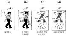
도 7의 (a)는 동상 장치에서의 사람 인식처리의 대상이 되는 입력 화상의 도면, 도 7의 (b)는 동(同) 처리에 의한 살색영역 검출결과를 나타내는 화상의 도면, 도 7의 (c)는 동 처리에 의한 살색영역을 포함하는 에지 화상의 도면, 도 7의 (d)는 동 처리에 의한 사람 인식 결과를 나타내는 에지 화상의 도면.FIG. 7A is a diagram of an input image that is a subject of a person recognition process in the in-phase device, and FIG. 7B is a diagram of an image showing the result of detecting the skin color region by the same process; FIG. (c) is a figure of the edge image containing the flesh-colored area by the same process, and FIG. 7 (d) is the figure of the edge image which shows the person recognition result by the same process.
도 8은, 동상 장치에 의해 이용되는 정규화 색공간의 개념도.8 is a conceptual diagram of a normalized color space used by an in-phase device.
도 9는, 동상 장치에서의 사람 인식처리 플로우에 포함되는 살색영역 검출 처리의 플로우도.Fig. 9 is a flow chart of the skin color region detection process included in the person recognition processing flow in the in-phase device.
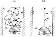
도 10의 (a)는 동상 장치에서의 사람 인식처리 플로우에 포함되는 투표에 의한 두부(頭部)형상 검출처리에 이용되는 투표 범위의 도면, 도 10의 (b)는 투표에 의한 두부검출을 설명하는 개념도.FIG. 10 (a) is a diagram of a voting range used for head shape detection processing by voting included in a person recognition processing flow in a frostbite apparatus, and FIG. 10 (b) shows head detection by voting. Conceptual diagram illustrating.
도 11은, 동상 장치에서의 사람 인식처리 플로우에 포함되는 투표에 의한 두부형상 검출처리의 플로우도.Fig. 11 is a flow chart of the head shape detection process by voting included in the person recognition processing flow in the frostbite apparatus.
도 12의 (a)는 동상 장치에서의 레이저 레이더에 의한 장애물 거리측정을 설 명하는 평면도, 도 12의 (b)는 동 레이저 레이더에 의한 거리측정 결과를 나타내는 도면.12A is a plan view illustrating obstacle distance measurement by a laser radar in an in-phase device, and FIG. 12B is a view showing a distance measurement result by the same laser radar.
도 13의 (a)는 동상 장치에서의 레이저 레이더에 의한 특정 형상물 거리측정을 설명하는 평면도, 도 13의 (b)는 동 레이저 레이더에 의한 거리측정 결과를 나타내는 도면.Fig. 13A is a plan view for explaining specific object distance measurement by a laser radar in an in-phase device, and Fig. 13B is a view showing a distance measurement result by the same laser radar;
도 14의 (a)는 동상 장치에서의 레이저 레이더에 의한 특정 형상물의 거리측정 결과의 그래프를 나타내는 도면, 도 14의 (b)는 동 거리 측정값의 차분의 그래프를 나타내는 도면.Fig. 14A is a diagram showing a graph of a distance measurement result of a specific shape by a laser radar in the in-phase device, and Fig. 14B is a diagram showing a graph of the difference between the same distance measurement values.
도 15는, 동상 장치에서의 특정 형상 인식처리의 플로우도.Fig. 15 is a flow chart of a specific shape recognition process in the in-phase device.
도 16은, 동상 장치에서의 사람 검지 정지영역을 설명하는 평면도.16 is a plan view illustrating a human detection stop region in the in-phase apparatus.
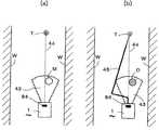
도 17의 (a)는 동상 장치에서의 사람 검지 경우의 정지동작을 나타내는 평면도, 도 17의 (b)는 사람 이외의 물체 지시의 회피동작을 나타내는 평면도.Fig. 17A is a plan view showing the stop operation in the case of detecting a person in the in-phase device, and Fig. 17B is a plan view showing the avoiding operation of an instruction other than a person.
도 18의 (a)는 동상 장치에서의 사람 이외의 물체 검지시의 회피동작을 나타내는 평면도, 도 18의 (b)는 사람 검지의 경우의 회피동작을 나타내는 평면도.Fig. 18A is a plan view showing an avoidance operation when detecting an object other than a person in the in-phase device, and Fig. 18B is a plan view showing the avoidance operation when detecting a person.
도 19의 (a)는 동상 장치에서 동 장치가 알아차린 사람에 대한 회피동작을 나타내는 평면도, 도 19의 (b)는 동 장치에 알아차리고 있지 않은 사람에 대한 정지동작을 나타내는 평면도.Fig. 19 (a) is a plan view showing an avoidance operation for a person noticed by the device in the in-phase device, and Fig. 19 (b) is a plan view showing a stop motion for a person not aware of the device.
도 20의 (a), 도 20의 (b)는 동상 장치에서의 사람에 대한 주의환기 행동을 설명하는 사시도.20 (a) and 20 (b) are perspective views illustrating attention ventilation behavior for a person in a frostbite apparatus.
도 21의 (a)는 동상 장치에서의 거리 측정장치의 좌표변환을 설명하는 사시 도, 도 21의 (b)는 동 평면도.Fig. 21 (a) is a perspective view illustrating the coordinate transformation of the distance measuring device in the in-phase device, and Fig. 21 (b) is a plan view of the same.
도 22는, 동상 장치에서의 자율 이동로봇의 기준좌표계와 정규화 화상좌표계와의 관계 설명도.Fig. 22 is an explanatory diagram illustrating the relationship between the reference coordinate system and the normalized image coordinate system of the autonomous mobile robot in the in-phase device.
도 23은, 동상 장치에서의 레이저 레이더 계측결과를 참조해서 화상 처리되는 화상을 나타내는 도면.Fig. 23 is a diagram showing an image processed by referring to laser radar measurement results in the in-phase device;
도 24는, 동상 장치에서의 레이저 레이더 계측결과를 참조해서 이루어지는 화상처리의 플로우도.24 is a flowchart of image processing performed with reference to laser radar measurement results in the in-phase device.
도 25의 (a)는, 동상 장치에서의 화상처리 결과를 참조해서 레이저 레이더 계측하는 장치의 평면도, 도 25의 (b)는 동측면도, 도 25의 (c)는 계측결과인 화상을 나타내는 도면.FIG. 25A is a plan view of the apparatus for laser radar measurement with reference to the image processing result in the in-phase device, FIG. 25B is an isometric view, and FIG. 25C is an image showing the measurement result. .
도 26은, 동상 장치에서의 화상처리 결과를 참조해서 이루어지는 레이저 레이더 계측 처리의 플로우도.Fig. 26 is a flowchart of laser radar measurement processing performed with reference to the image processing result in the in-phase device.
도 27의 (a)는 동상 장치에서 사람을 동 장치가 알아차리고 있다고 판단하는 화상을 나타내는 도면, 도 27의 (b)는 동일하게 알아차리고 있지 않다고 하는 화상을 나타내는 도면.FIG. 27A is a view showing an image in which the person in the in-phase device judges that the device is aware, and FIG. 27B is a view showing an image not being noticed in the same manner.
도 28은, 동상 장치에서 이용되는 사람까지의 거리와 얼굴의 살색면적의 관계 그래프를 나타내는 도면.Fig. 28 is a graph showing the relationship graph between the distance to the person used in the in-phase device and the flesh area of the face;
도 29는, 동상 장치에서의 사람 검출처리의 플로우도.29 is a flowchart of a person detection process in the in-phase apparatus.
도 30은, 동상 장치에서의 사람을 동 장치가 알아차리고 있는가 아닌가의 판단 처리의 플로우도.Fig. 30 is a flow chart of a judging process of whether or not the apparatus is aware of a person in the in-phase apparatus.
도 31의 (a), 도 31의 (b), 도 31의 (c)는 동상 장치에서의 촬상장치와 거리 측정장치의 조합을 설명하는 사시도.31 (a), 31 (b) and 31 (c) are perspective views illustrating the combination of the imaging device and the distance measuring device in the in-phase device.
[발명을 실시하기 위한 최선의 형태]Best Mode for Carrying Out the Invention
이하, 본 발명의 일실시형태에 관한 자율 이동로봇에 대해서, 도면을 참조해서 설명한다. 도 1은 본 장치의 블록 구성을 나타낸다. 자율 이동로봇(1)은, 주행하는 영역의 지도 데이터와 주행을 위한 각종 파라미터를 기억하는 기억수단(2)과, 목적지나 주행지령을 기억수단(2)에 입력하는 입력 지시수단(3)과, 목적지까지의 주행경로를 생성하는 경로 생성수단(41)과, 장애물이 되는 물체를 포함하는 주행경로 상의 환경정보를 취득하는 환경정보 취득수단(6)과, 주행을 행하기 위한 주행수단(5)과, 환경정보 취득수단(6)에서 얻어진 정보와 기억한 지도 데이터에 근거해서 자기위치를 인식하는 자기위치 인식수단(42)과, 이 자기위치 인식수단(42)에 의해 자기위치를 인식하면서 장애물을 회피하도록 주행수단(5)을 제어하는 주행 제어수단(4)을 구비하고 있다.EMBODIMENT OF THE INVENTION Hereinafter, the autonomous mobile robot which concerns on one Embodiment of this invention is demonstrated with reference to drawings. 1 shows a block configuration of the apparatus. The autonomous
또한, 환경정보 취득수단(6)은, 주행경로 상의 환경의 화상을 촬상하는 촬상장치(71)와, 그것에 의해 촬상된 화상 데이터를 연산 처리해서 미리 결정한 속성을 가지는 물체를 추출하는 화상인식 처리수단(72)(상기 2자는 화상정보 취득수단(7)을 구성)과, 주행경로 상의 환경 내에 존재하는 물체를 검출하고, 그 물체까지의 거리와 물체의 방향을 측정하는 거리 측정장치(81)와, 그것에 의해 측정된 거리 데이터를 연산 처리하는 거리정보 해석수단(82)(상기 2자는 거리정보 취득수단(8)을 구성)과, 화상인식 처리수단(72)에서 얻어진 미리 결정한 속성을 가지는 물체의 정보와 거리정보 해석수단(82)에서 얻어진 거리정보에 근거해서 환경정보를 인식하는 환경 인식수단(9)을 구비하고 있다. 환경 인식수단(9)은 주행경로 상의 환경정보를 주행 제어수단(4)에 출력한다.The environmental
자기위치 인식수단(42)은, 예컨대 주행수단(5)에 설치된 인코더(encoder)나 내장된 자이로 등을 이용하여, 주행 중에 자기위치가 지도 위의 어느 위치에 있는가를 추정하는 동시에, 환경정보 취득수단(6)에서 얻어진 자기위치 정보를 이용해서 자기위치 추정값을 보정한다.The magnetic position recognizing means 42 estimates where the magnetic position is on the map while traveling by using an encoder installed in the traveling means 5 or a built-in gyro. The magnetic position estimation value is corrected using the magnetic position information obtained in (6).
환경정보 취득수단(6)으로부터 얻어지는 자기위치 정보로서, 예컨대, 동 수단(6)에 의해 인식 가능한 표식(標識)을 미리 주행환경 내에 설치해 두고, 또한, 그 표식을 지도 데이터에 등록해 두는 것에 의해, 주행 중에 그 표식을 인식해서 자기위치 정보로 할 수 있다. 주행 제어수단(4)은, 자기의 추정 위치를 기준으로 해서 보내져 온 상대 위치에 의한 표식위치 정보를 바탕으로, 지도 위의 등록 표식을 탐색한다. 표식이 검출되면, 그 표식의 위치를 기준으로 해서 상기 상대 위치정보로부터 자기위치 인식을 할 수 있다. 표식을 2개 이상 검출할 수 있으면, 자기위치는 일의(一意)로 결정된다.As the magnetic position information obtained from the environmental information acquisition means 6, for example, a mark recognizable by the
또한, 환경정보 취득수단(6)은, 주행 중에 장애물을 검출하여, 그 위치정보를 주행 제어수단(4)으로 보내고, 주행 제어수단(4)은, 그 장애물을 피하도록 주행경로를 수정하여, 제어 출력을 주행수단(5)에 보낸다. 이렇게, 자율 이동로봇(1)은, 자기위치를 인식해 장애물을 회피하면서 주행경로를 따라 지시된 목적지까지 주행한다.In addition, the environmental
도 2는 자율 이동로봇(1)의 외관을 나타낸다. 이 자율 이동로봇(1)은, 거리정보 취득수단(8)의 거리 측정장치(81)로서, 레이저 레이더(레이저 레인지 파인더)(83)를 구비하고 있고, 화상정보 취득수단(7)의 촬상장치(71)로서, 자율 이동로봇 본체(10)에 대해서 회전(수평회전)가능한 회전기구(70a)에 설치된 카메라(70)를 구비하고 있다. 또한, 이 장치는, 예컨대, 전지에 의해 차륜(52)이 구동되어 주행하는 것이며, 차륜(52)의 회전을 모니터하는 것에 의해 주행거리의 계측이 행하여지고, 자기위치 인식의 정보로 된다. 이하, 화상정보 취득수단으로부터 순차로, 본 장치의 상세를 설명한다.2 shows the appearance of the autonomous
(화상정보 취득수단의 구성)(Configuration of Image Information Acquisition Means)
본 발명의 자율 이동로봇(1)은, 레이저 레이더나 소나 등의 거리 계측수단에 의해 얻어지는 부분적인 장애물 검출결과와 화상처리에 의해 얻어지는 장애물 검출결과의, 2종류의 장애물 정보를 종합해서 장애물이 무엇인가를 판단한다. 우선, 화상처리에 의해 장애물 검출결과를 얻는 것에 대해서 설명한다. 도 3 및 도 4는 화상정보 취득수단(7)의 블록 구성을 나타낸다. 화상인식 처리수단(72)은, 컬러 카메라(촬상장치)(70)로부터 입력되는 화상신호를, A/D 변환기(61)에 의해 디지털화하고, 메모리(62)에 디지털 화상으로서 보존한다. 화상에 대해서 연산 처리를 하는 CPU(64)에는, 프로그램 메모리(63)로부터 처리 알고리즘이 기재된 소프트웨어가 호출되고 있고, CPU(64)는 그 소프트웨어를 사용하여 이하에 나타내는 처리 순서에 의해 디지털 화상으로부터 사람의 검출 처리를 실행한다. 화상처리 결과는, 통신 제어부(65)에 의해 환경 인식수단(9)을 경유해서 주행 제어수단(4)으로 송신된다.The autonomous
또한, 로컬에, 즉 자율 이동로봇 본체(10)의 부분에서 조작자가 자율 이동로봇 본체(10)의 기기를 조작하여, 화상정보 취득수단(7)(카메라(70)와 화상인식 처리수단(72))의 조작이나 처리 결과의 표시를 행하기 위해서, 도 4에 나타내는 바와 같이, 키보드 제어부(66), 키보드(67), 표시 제어부(68) 및 표시부(69)를 화상인식 처리수단(72)에 구비해도 좋다. 또한, 통신 제어부(65)를 통해서, 외부에서 화상정보 취득수단(7)의 조작을 제어할 수도 있다.Further, the operator manipulates the device of the autonomous
(촬상장치)(Imaging device)
촬상장치(71)에 대해서 설명한다. 도 5의 (a) 및 도 5의 (b)는 1개의 고정 카메라로 이루어지는 촬상장치(71)를 나타내고, 도 5의 (c)는 그것에 의해 촬상된 화상을 나타낸다. 이 카메라(70)는, 자율 이동로봇 본체(10)에 고정되고 있어, 자율 이동로봇 본체(10)의 진행방향(10a), 전방의 경치를 화상(11)과 같이 촬상한다. 이 카메라(70)의 좌표계는, 자율 이동로봇 본체(10)에 고정해서 정의된 기준좌표계와 함께 변하게 된다.The
(화상인식 처리수단)(Image recognition processing means)
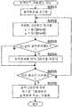
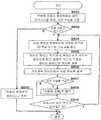
촬상장치(71)에서 취득된 화상 데이터를 화상인식 처리수단(72)에 의해 연산 처리하여, 사람이나 특정 물체의 검출을 행하는 방법에 대해서 설명한다. 여기에, 인체의 부위에 관한 속성으로서, 사람의 두부, 특히 얼굴의 살색을 이용한다. 도 6은 화상으로부터 사람을 인식하기 위한 전체의 처리 흐름(사람 인식처리 플로우)을 나타낸다. 촬상장치(71)인 컬러 카메라에 의해, 자율 이동로봇의 주변상황, 예컨대 진행방향 전방이 촬상되고(S101), 그 아날로그 화상신호가 A/D 변환기(61)에 의해 디지털화되어(S102), 색의 3성분인 R, G, B(빨강, 초록, 파랑)로 이루어지는 각 색성분 디지털 화상이 메모리(62)에 보존된다(S103). 다음에, CPU(64)에 있어서 색의 3성분을 평균한 휘도 I=(R+G+B)/3에 의한 화상이 작성되어, 그 휘도 화상이 메모리(62)에 보존된다(SlQ4). 다음에, 화상 중에서 살색영역의 검출처리가 행하여져(S105), 검출된 살색영역 내에 대해서 에지 화상에 근거하는 두부형상 검출처리가 행하여진다(S106). 검출된 두부의 위치가 사람 인식 결과로서 환경 인식수단(9)에 출력된다.The method of performing arithmetic processing on the image data acquired by the
상술의 처리의 흐름 모양을, 처리 대상이 되는 화상에 의해 설명한다. 도 7의 (a)는 입력 화상, 도 7의 (b)는 살색영역 검출결과의 화상, 도 7의 (c)는 에지 화상 위의 살색영역을 나타내는 화상, 도 7의 (d)는 인식 결과를 출력한 화상을 각각 나타내고 있다. 우선, 입력 화상(21)에 있어서 살색영역(24~26)이 검출되어(화상(23)), 검출된 살색영역(24~26)에 대해서만, 에지 화상(27) 위에서 두부형상 검출처리가 행하여지므로, 효율이 좋은 처리를 행할 수 있다.The flow pattern of the above-described processing will be described with an image to be processed. Fig. 7A shows an input image, Fig. 7B shows an image of a skin color detection result, Fig. 7C shows an image of a skin color area on an edge image, and Fig. 7D shows a recognition result. Each of the output images is shown. First, the
화상에의 살색영역의 검출에 이용되는 정규화 r-g 공간에 대해서 설명한다. 도 8은 정규화 r-g 공간(평면)을 나타낸다. 컬러 화상에서의 R성분, G성분은, 각 화소의 컬러 성분의 휘도값(R, G, B)을 이용하여, 계산식r=R/(R+G+B), g=G/ (R+G+B)에 의해 정규화되어, 정규화된 r, g값이 얻어진다. 일반적으로, 사람의 살색은, 도 8에 나타내는 바와 같이, r-g 평면상에서 1개의 영역(20)을 형성하므로, 컬러 화상의 각 화소로부터 구한 정규화 r, g값이, 이 영역(20)에 들어가는가 아닌 가에 의해, 그 화소가 살색인가 아닌가가 판정된다. 이 살색영역(20)은 미리 많은 화상의 살색 데이터에 근거해서 작성된 것이다.The normalized r-g space used for detecting the skin color region in the image will be described. 8 shows the normalized r-g space (plane). The R component and the G component in the color image are calculated using the luminance values R, G, and B of the color component of each pixel, and the formula r = R / (R + G + B) and g = G / (R + Normalized by G + B), normalized r and g values are obtained. In general, as the skin color of a person forms one
살색영역의 검출 처리의 상세에 대해서 설명한다. 도 9는 살색영역 검출처리 플로우를 나타낸다. 우선, CPU(64)에 있어서, 메모리(62)의 살색영역을 기억하는 살색화상 부분이 초기화된다(S201). 다음에, 입력 화상 1개의 화소에 대해서 R성분, G성분이 계산식 r=R/(R+G+B), g=G/(R+G+B)에 의해 정규화된다(S202). 이 정규화된 R성분, G성분의 r, g값이 살색영역(20)내에 있는가 아닌가가 검사되어 (S203), 살색영역 내이면 그 화소는 살색이라고 판정되어(S203에서 Y), 살색화상의 대응하는 위치에 살색 플래그(flag)가 세워진다(S204). 입력 화상의 전체 화소에 대해서 이들 처리가 종료후(S205에서 Y), 살색화상 위에서, 살색 플래그가 세워진 화소가 그룹화되어, 그 그룹을 바탕으로, 예컨대 직사각형의 영역으로 이루어지는 살색영역이 작성된다. 이러한 살색영역에 라벨링(labeling) 처리가 이루어져, 각 영역의 구별이 행하여지고, 전출(前出)의 도 7의 (b)에 나타내는 바와 같이 살색영역(24~26)이 얻어진다(S206).The detail of the detection process of the light-colored area is demonstrated. 9 shows a skin area detection processing flow. First, in the
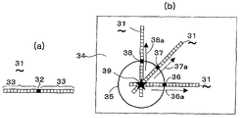
검출된 살색영역으로부터 투표 처리에 의해 두부형상을 검출하는 방법에 대해서 설명한다. 도 10의 (a)는 투표 처리에서 이용되는 투표 범위를 정하는 투표 프레임를 나타내고, 도 10의 (b)는 그 투표 프레임의 사용법을 나타낸다. 두부형상검출은, 두부가 거의 원형의 형상을 가지는 것을 이용해서 행하여진다. 예컨대, 사람의 얼굴을 포함하는 화상에 에지 추출의 화상처리(예컨대 화상 휘도에 대한 미분처리)를 실시한 에지 화상(34)에, 얼굴의 윤곽을 나타내는 에지화소 집합(35)이 얻 어졌다 한다. 이 에지 화상(34)의 각 화소점을 투표 빈(bin)(투표함)으로 하는 투표 공간이 설정된다. 또한, 에지화소의 집합(35)의 각 화소에 대해서, 예컨대, 화소(36)에 대해서 휘도 구배방향(36a)과 같이, 각 화소에 휘도 구배방향이 결정되어 있다고 한다. 일반적으로, 사람의 얼굴과 그 배경의 화상에는 농담(濃淡)변화가 있고, 얼굴윤곽의 에지화소에서의 휘도 구배방향은, 얼굴의 중심에서 밖으로 또는 밖으로부터 안으로 향하는 것이 된다.A method of detecting the head shape from the detected skin color area by the voting process will be described. Fig. 10A shows a voting frame for determining a voting range used in the voting process, and Fig. 10B shows how to use the voting frame. Head shape detection is performed using the head having an almost circular shape. For example, an edge pixel set 35 showing an outline of a face is obtained in an
그래서, 검출 대상이 되는 두부의 크기를 포함하도록 설정된 봉(棒) 모양의 투표 프레임(31)의 중앙점(32)을, 예컨대 에지화소(36)에 맞추어, 투표 프레임(31)의 방향을 그 에지화소(36)에서의 휘도 구배방향(36a)으로서, 투표 프레임(31)의 각 투표 빈(33)과 겹치는 투표 공간의 모든 투표 빈에 투표한다. 이러한 투표를 얼굴의 윤곽을 나타내는 에지화소집합(35)의 모든 화소에 대해서 행하면, 별표(39)로 나타내는 바와 같이, 얼굴의 중심에 있는 투표 빈에는, 다른 것보다도 많은 투표가 이루어지게 된다. 이렇게, 두부의 외형 위에 따르는 투표 처리의 결과는, 두부의 중심부에 집적하므로, 투표 공간내에서 미리 결정된 문턱치보다도 큰 투표치를 가지는 투표 빈이 있을 때, 그 투표 빈을 중심으로 하는 두부가 존재한다고 판정된다.Thus, the direction of the
두부형상의 검출처리의 상세에 대해서 설명한다. 도 11은 두부형상 검출처리 플로우를 나타낸다. 우선, CPU(64)에 있어서, 예컨대 살색영역(24)에 대응하는 휘도화상을 미분하여, 휘도 구배화상ㆍ에지 화상을 작성한다(S301). 다음에, 투표치를 기억하는 메모리 공간인 투표 공간을 초기화한다(S302). 다음에, 살색영역(24) 내의 모든 에지화소에 대해서, 각 에지화소의 휘도 구배방향에, 봉 모양의 투표 범위 프레임을 배치해서 선택된 투표 공간의 각 투표 빈에 투표가 행하여진다(S303).살색영역(24)내의 모든 에지화소에 대해서 투표 종료후(S304), 미리 결정된 문턱치 이상의 투표치를 가지는 투표 빈의 존재가 조사되고, 그러한 투표 빈이 존재하는 경우(S305에서 Y), 그 살색영역의 중심위치가 두부위치로서 통신 제어부(65)를 통해서 환경 인식수단(9)에 출력된다(S306). 모든 살색영역에 대해서 상기의 처리가 행하여지고, 두부형상 검출처리가 종료한다(S307). 전출(前出)의 도 7의 (d)의 경우, 살색영역(24, 25, 26) 중, 살색영역(24)이 두부 형상으로서 검출되어, 별표(29)의 위치가 두부위치로 된다.Details of the head-shaped detection processing will be described. 11 shows a head shape detection processing flow. First, in the
화상 위에서 살색영역으로부터 두부위치로서 검출된 위치의, 실제 공간에서의 존재 방향을 특정하는 방법에 대해서 설명한다. 실제 공간에서의 사람 존재 방향의 특정은, 화상인식 처리수단(72)에서 행하여진다.A method of specifying the presence direction in the actual space of the position detected as the head position from the skin color region on the image will be described. The direction of the person presence in the real space is specified by the image recognition processing means 72.
촬상장치(71)가 전술의 도 5에 나타낸 카메라(70)인 경우, 화상 위의 얼굴의 크기와 화상 위의 얼굴의 위치로부터, 사람이 있는 개략의 방향을 산출할 수 있다. 이상과 같이 해서 특정되었다, 사람이 있는 개략의 방향은, 사람이 존재하는 방향의 후보로 된다. 화상인식 처리수단(72)에서 사람이 존재하는 방향의 후보라고 인식된 이들의 결과는, 화상 위의 두부위치 검출결과와 같이, 통신 제어부(65)로부터 환경 인식수단(9)에 보내진다. 만약, 복수의 인식 결과가 있으면, 그 모든 결과가 보내진다.In the case where the
(거리정보 해석수단)(Distance information interpretation means)
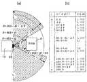
레이저 레이더에 의한 장애물의 위치 인식에 대해서 설명한다. 도 12의 (a)는 레이저 레이더(83)에 의한 장애물의 거리측정을 나타내고, 도 12의 (b)는 동 레이저 레이더에 의한 거리측정 결과를 나타낸다. 거리 측정장치(81)로서, 레이저 레이더(83)를 이용한 경우, 예컨대 일정한 각도 △θ마다 레이저 빔(beam)을 발사 및 수광하면서 소정의 각도범위가 수평으로 스캔된다. 레이저 레이더(83)에 의해 얻어지는 거리 데이터는, 반사광이 수광되지 않는가 또는 레이저 광반사 물체가 소정의 거리보다 먼 곳에 있는 경우의 거리(L) 이상의 데이터 및 장애물(O)로부터의 반사광에 의해 얻어진 장애물(O)의 거리(L1, L2) 등으로 된다. 일정한 각도 △θ를, 예컨대 0.5°로서 측정한, 일련의 거리 데이터를 이용하면, 특정 형상물의 위치를 인식할 수 있다(특개2002-202815호 공보 참조).The position recognition of the obstacle by a laser radar is demonstrated. 12A shows the distance measurement of the obstacle by the
이러한 거리 데이터를 거리정보 해석수단(82)에서 연산 처리해서 검출된 장애물의 폭이, 미리 결정한 범위 내인 물체(특정 형상물)의 경우, 그 물체를, 예컨대 사람의 발이라고 해서 사람의 후보를 인식할 수 있다. 이렇게, 기억부(2)에 미리 설정한 폭 이하 또는 미리 설정한 폭의 범위 내의 물체가 검출된 위치에, 사람(의 발)이나 의자가 존재할 가능성이 있다고 판단된다. 그 특정 형상물의 (분포)위치는, 후술하는 바와 같이, 그 폭의 스캔에 필요한 측정점수(j)와, 그 폭 내에서의 물체의 거리 및 스캔 각도세트(組), D(i), θ(i), 0≤i<j로서 인식된다. 이러한 거리 및 방향 데이터가, 거리정보 해석수단(82)으로부터 환경 인식수단(9)에 보내진다.In the case of an object (specific shape) whose width of the obstacle detected by calculating the distance data by the distance information analyzing means 82 is within a predetermined range, the object can be recognized as a person's foot, for example, as a person's foot. Can be. In this way, it is judged that a person (foot) or a chair may be present at a position where an object within a predetermined width or a range of a predetermined width is detected in the
환경 인식수단(9)에서는, 화상인식 처리수단(72)에서의 화상인식 결과로부터 얻어진, 예컨대 사람 존재의 후보방향과, 거리정보 해석수단(82)으로부터 얻어진 사람 존재 가능성의 방향이 비교된다. 양자가 거의 일치한 경우, 그 방향이 사람의 존재 방향이라고 판단되어, 그 방향과 거리가 주행 제어수단(4)에 보내진다.In the
또한, 거리 측정장치(81)인 레이저 레이더(83)에 의해 얻어진 특정 형상물(사람의 후보 위치)의 데이터 D(i), θ(i)는, 레이저 레이더(83)의 좌표계(센서 좌표계)의 데이터이다. 그래서, 거리정보 해석수단에 있어서, 후술의 도 21에 나타내는 바와 같이, 특정 형상물의 위치가 좌표 변환되어, 자율 이동로봇 본체(10)의 좌표계(XR, YR)로 표현된다.In addition, the data D (i) and θ (i) of the specific shape (the candidate position of the person) obtained by the
(특정 형상물의 검출)(Detection of specific shape)
레이저 레이더에 의한 특정 형상물의 위치 인식에 대해서 설명한다. 도 13의 (a)는 레이저 레이더에 의한 거리측정의 모양을 나타내고, 도 13의 (b)는 레이저 레이더에 의한 거리측정 결과를 나타낸다. 거리 측정장치(81)로서, 레이저 레이더(83)를 이용한 경우, 예컨대 일정 각도 △θ마다 레이저 빔을 발사 및 수광하면서 소정의 각도 범위를 수평으로 스캔하고, 도 13의 (b)에 나타내는 것과 같은, 레이저 반사물체(OB1, 0B2)와 레이저원과의 거리 D(i)를 나타내는 일련의 데이터가 얻어진다. 스캔에서의 각도 θ=0으로부터 계산해서 i번째의 거리 데이터가 D(i)이다. 이하의 설명에 있어서, 소정의 스캔 각도 범위에 있어서, N회의 거리측정이 행하여진다(0≤i<N)라고 한다.The position recognition of the specific shape by a laser radar is demonstrated. Fig. 13A shows the shape of the distance measurement by the laser radar, and Fig. 13B shows the result of the distance measurement by the laser radar. In the case of using the
특정 형상물을 스캔한 전후의 거리 데이터의 특성에 대해서 설명한다.The characteristic of the distance data before and after scanning a specific shape is demonstrated.
도 14의 (a)는 특정 형상물까지의 거리 데이터 D(i)의 그래프를 나타내고, 도 14의 (b)는 동 거리 데이터의 차분 △D(i)의 그래프를 나타낸다(이들의 그래프는 일반적인 그래프로서 도시되고 있고, 도면 중의 파라미터 n을, n=m으로 놓은 경우, 전출의 도 13의 측정 결과에 일치한다). 일반적으로, 장애물이 측정되면, 그 장애물의 범위에 있어서, 거리 데이터 D(i)가 낮은 값을 나타낸다(i=m, m+1 ,ㆍㆍ, n+2의 점). 또한, 측정된 거리 데이터 D(i)는, 장애물의 전후에서, 원(遠)-근(近)-원(遠)이 되는 거리 변화를 나타내므로, 거리의 차분 △D(i)는, 장애물의 경계의 부분에서 정부(正負)의 피크를 나타낸다(i=m, n+3의 점).Fig. 14A shows a graph of the distance data D (i) to a specific shape, and Fig. 14B shows a graph of the difference ΔD (i) of the same distance data (these graphs are general graphs). And the parameter n in the figure is set to n = m, which corresponds to the measurement result of FIG. Generally, when an obstacle is measured, the distance data D (i) shows a low value in the range of the obstacle (points of i = m, m + 1, ..., n + 2). In addition, since the measured distance data D (i) shows a distance change that becomes a circle-root-circle before and after the obstacle, the difference ΔD (i) of the distance is an obstacle. The peak of an indefinite is shown in the part of the boundary of (i = m, the point of n + 3).
그래서, 거리의 차분 값의 그래프에 있어서, 미리 결정한 문턱치(DR, -DR)에 의해, 특정 형상물의 경계를 검출할 수 있다. 또한, 레이저 레이더(83)에 대향하는 특정 형상물 표면의 거리 변화에 대해서, 최대치의 문턱치(dd, -dd)를 정해서 특정 형상물의 깊이의 판정을 행할 수 있다. 예컨대, 지정하는 특정 형상물이 기둥 모양물체이며, 검출할 필요가 있는 기둥 모양물의 안에서 최대의 폭이 rr×2일 때에는, dd=rr로 설정할 수 있다.Therefore, in the graph of the difference value of distance, the boundary of a specific shape can be detected by predetermined threshold values DR and -DR. Moreover, with respect to the distance change of the surface of the specific shape object which opposes the
또한, 특정 형상물까지의 거리의 대표치를 주는 데이터 번호(H)로서, 특정 형상물의 경계의 거리 데이터를 주는 데이터 번호를 이용하고, 예컨대, 도 14의 (a)의 경우, 번호 m과 (n+2)를 이용하고, H=int(m+(n+2))/2)이라고 한다. 여기에서, int(X)는, X를 초과하진 않는 최대의 정수를 주는 함수이다. 특정 형상물의 검출 플로우에 있어서, 이 거리의 대표치를 주는 번호(H), 그 번호에서의 거리 데이터 D(H), 각도 데이터 θ(H)가 기억된다. 또한, 고려해야 할 특정 형상물이 복수 라면, 이들의 복수의 데이터가 기억된다.As the data number H giving a representative value of the distance to the specific shape, a data number giving the distance data of the boundary of the specific shape is used. For example, in the case of Fig. 14A, the numbers m and (n + 2) is used, and H = int (m + (n + 2)) / 2). Here, int (X) is a function that gives the largest integer that does not exceed X. In the detection flow of the specific shape, a number H giving a representative value of this distance, distance data D (H) at that number, and angle data θ (H) are stored. In addition, if there are a plurality of specific shapes to be considered, a plurality of these data are stored.
또한, 특정 형상물의 거리 측정치의 연속하는 점의 개수의 상한에 있어서 문턱치(DN)를 정해 두고, 측정 대상물의 거리 측정치가, 특정 형상물의 거리 측정점d락라 생각되는 점의 갯수 C가, 문턱치(DN) 이하인 경우(C <DN), 그 측정 대상물을 특정 형상물이라고 판정한다. DN의 값은, 고정 값이라도 좋다. 또한, 예컨대 1개의 거리 데이터로 추정할 수 있는 검출물의 크기를, D(i)×sin(△θ)로 가정하고, 특정 형상의 크기를, D(i)×sin(△θ)×C라고 추정한다. 특정 형상의 크기를 미리 가정하고, 거리마다 DN의 값을 변화시켜도 좋다. 즉, 특정 형상물의 최대의 폭을 Omax라고 하면, 예컨대 D(m)의 DN을, Omax/(D(m)×sin(△θ)) 이상의 최소의 정수f라 할 수 있다.In addition, the threshold DN is set at the upper limit of the number of consecutive points of the distance measurement value of the specific shape, and the number C of points where the distance measurement value of the measurement object is considered to be the distance measurement point d of the specific shape is the threshold value DN. ) (C <DN), the measurement object is determined to be a specific shape. The value of DN may be a fixed value. In addition, it is assumed that the size of the detected object that can be estimated by one distance data is, for example, D (i) × sin (Δθ), and the size of the specific shape is D (i) × sin (Δθ) × C. Estimate. Assuming the size of a specific shape in advance, the value of DN may be changed for each distance. In other words, when the maximum width of a specific shape is Omax, for example, DN of D (m) can be regarded as a minimum constant f equal to or more than Omax / (D (m) x sin (Δθ)).
측정 데이터로부터 특정 형상물을 인식하는 처리 플로우에 대해서 설명한다. 도 15는 특정 형상 인식처리 플로우를 나타낸다. 도 13에 나타낸 측정 결과에 따라 설명한다. 각 처리 루틴마다 데이터 번호 i가 1씩 증가되고(S402), 인접하는 거리 데이터 차 △(i, i-1)=D(i)-D(i-1)의 크기가 조사된다(S405). 도 13에 나타내는 예에서는, i=m에 있어서, △(m, m-1)<-DR이므로 스텝 S407으로 가고, C=1, m=i이 된다. 그리고 i=m+1에 있어서|△(m+2, m+1)|≤DR 또한, D(m+1)-D(m)<dd이므로, 처리는 스텝 S408, S409, S410을 통해서, C=2가 된다.A processing flow for recognizing a specific shape from measurement data will be described. 15 shows a specific shape recognition processing flow. It demonstrates according to the measurement result shown in FIG. The data number i is incremented by 1 for each processing routine (S402), and the size of the adjacent distance data difference Δ (i, i-1) = D (i) -D (i-1) is examined (S405). In the example shown in FIG. 13, since i = m, since (D, m-1) <-DR, it will go to step S407 and C = 1, m = i. And in i = m + 1 | (DELTA) (m + 2, m + 1) | <DR Since D (m + 1) -D (m) <dd, a process goes through step S408, S409, S410, C = 2.
또한, i=m+2에 있어서,|△(m+2, m+1)|≤DR 또한, D(m+2)-D(m+1)<dd이므로, 동일하게 해서 C=3이 된다.Further, i = m + 2, | Δ (m + 2, m + 1) | ≦ DR and D (m + 2) -D (m + 1) <dd, so that C = 3 is the same. do.
또 i=m+3에 있어서, △(m+3, m+2)>DR이므로, 처리는 스텝 S412 .S413, S414을 통과한다. 또한, int(x)는 x를 초과하지 않는 최대의 정수를 되돌려 주는 함수 이다.Further, at i = m + 3, since? (M + 3, m + 2)> DR, the process passes through steps S412.S413, S414. Also, int (x) is a function that returns the largest integer not exceeding x.
이렇게 해서 D(m), D(m+1), D(m+2)이 1개의 특정 형상물로부터의 반사에 의해 얻어진 거리 데이터라고 판단되어, 복수 있는 특정 형상물의 j번째의 특정 형상물까지의 거리가, H(j)=int((m+m+2)/2)=(m+1)번째의 거리 데이터로 나타내진다(S414). 또, 스텝 S411, S415에서는 C=0로서 C가 리셋 된다.In this way, it is judged that D (m), D (m + 1), and D (m + 2) are distance data obtained by reflection from one specific shape, and the distance to the j-th specific shape of a plurality of specific shapes is determined. Is represented by the distance data of H (j) = int ((m + m + 2) / 2) = (m + 1) th (S414). In step S411 and S415, C is reset as C = 0.
거리 측정장치(81)로서 거리 측정 가능한 초음파 센서를 이용한 경우에 대해서 설명한다. 초음파 센서는 저렴하고, 자율 이동로봇 본체(10)의 주위에 복수 설치할 수 있다. 전술의 화상인식 처리수단(72)이, 어떤 방향에 사람 후보가 존재한다고 판단한 경우, 그 방향에 검출영역을 갖는 초음파 센서의 검출결과(거리)에 대해서, 거리정보 해석수단(82)은, 그 검출 결과가 벽(壁)을 검출한 것인가 아닌가를 판단한다. 벽이라고 판단하지 않은 경우를 그 사람 후보를 사람이라고 한다. 예컨대, 초음파 센서에 의해 계측된 물체까지의 거리가, 기억된 지도 위의 물체(벽)까지의 거리와 일치하지 않을 때, 거리정보 해석수단(82)은, 계측된 물체를 사람의 후보로서 인식한다. 거리정보 해석수단(82)에 있어서, 지도 위에 없는 물체는 사람일 가능성이 높다고 판단하는 것에 의해, 간단한 사람 검출을 실현할 수 있다. 화상인식 처리수단(72)의 판단 결과에, 초음파 센서의 검출 결과를 조합시키는 것에의해, 벽에 걸쳐진 사람의 사진 등을 사람으로 오인식하는 일이 없어진다. 기억된 지도 위의 물체(벽)까지의 거리의 계산에 대해서는, 후술된다.The case where the ultrasonic sensor which can measure distance as a
(주행 제어수단)(Drive control means)
주행제어에 대해서 설명한다. 주행 제어수단(4)은, 환경정보 취득수단(6)으 로부터 사람이라고 인식된 대상 물체의 방향과 거리가 보내져 온 경우, 사람으로 인식되는 물체가 자율 이동로봇 본체(10)의 진행 방향에 있고 또한, 미리 결정한 거리 내에 있는 경우에는 정지하도록 주행수단(5)을 제어하여, 사람에 대해서 안전을 확보한다. 또한, 주행 제어수단(4)은, 사람으로 인식되는 물체가 자율 이동로봇 본체(10)의 진행 방향에 없는 경우, 다른 장애물이 있으면 회피를 행하고, 다른 장애물이 없으면 그대로 주행을 계속하도록 주행수단(5)을 제어한다.The traveling control will be described. The travel control means 4, when the direction and the distance of the target object recognized as a person from the environmental information acquisition means 6 have been sent, the object recognized as a person is in the advancing direction of the autonomous
사람 검지 정지영역에 대해서 설명한다. 도 16은 초음파 센서(84)에 근거하는 사람 검지 정지영역(43)을 나타낸다. 또한, 도 17의 (a)는 사람 검지의 경우의 정지동작을 나타내고, 도 17의 (b)는 사람 이외의 물체 검지시의 경우의 회피동작을 나타낸다. 도 16에 나타내는 바와 같이, 자율 이동로봇(1)으로부터의 거리(D1), 진행 방향(10a)에 대한 방향각±Φ내의 영역을 사람 검지 정지영역(43)이라고 해서, 이 영역(43)에 있어서 검지한 물을 사람(M)이라고 판단한 경우, 도 17의 (a)에 나타내는 바와 같이, 자율 이동로봇(1)은 정지한다. 초음파 센서(84)를 이용하는 것에 의해, 저렴하게 이러한 사람 검지 정지영역(43)을 설정할 수 있다. 사람이 아니라고 판단한 경우는, 도 17의 (b)에 나타내는 바와 같이, 자율 이동로봇(1)은, 소정의 주행경로(44)로부터 떨어져, 장애물(O)을 회피한 주행경로(45)를 따라 목적지(T)를 향해서 이동을 계속한다.The human detection stop area will be described. 16 shows a person detecting
또한, 주행 제어수단(4)이, 주행수단(5)을 제어해서 자율 이동로봇 본체(10)를 주행시키는 다른 방법으로서, 레이저 레이더에 의한 거리측정 정보에 근거하고, 예컨대, TangentBug(The Intemational Journal of Robotics Research, Vo1.17, No.9, September 1998. pp.934-953) 등의 방법을 이용하여, 장애물을 회피해서 목적지를 향해서 이동을 계속하도록 해도 좋다.Further, the traveling control means 4 controls the traveling means 5 to drive the autonomous
검출 물체 회피의 다른 방법에 대해서 설명한다. 도 18의 (a)는 사람 이외의 물체 검지시의 회피동작을 나타내고, 도 18의 (b)는 사람 검지의 경우의 회피동작을 나타낸다. 주행 제어수단은, 사람으로 인식되는 물체가 자율 이동로봇 본체의 진행 방향에 있는 경우, 그 사람으로 인식되는 물체로부터 미리 결정한 거리를 사이를 두고 회피해서 주행하도록 주행수단을 제어한다. 이 경우, 검출된 물체를 사람이라고 인식한 경우와, 사람이 아니라고 판단된 경우에, 그 검출 물체를 회피하는 방법을 변경하도록 해도 좋다. 예컨대, 거리 측정장치(81)로서 레이저 레이더(83)를 이용한 경우에서, 장애물(O)이 검출영역(46)으로서 설정한 범위에 들어가지 않도록 경로를 설정할 경우에, 미리 설정한 2종류의 검출반경(R1, R2)을 바꾼다.Another method of avoiding the detected object will be described. FIG. 18A shows the avoidance operation when detecting an object other than a person, and FIG. 18B shows the avoidance operation when detecting a person. The travel control means controls the travel means so that when an object recognized as a person is in the advancing direction of the autonomous mobile robot body, it travels by avoiding a predetermined distance from the object recognized as the person. In this case, when the detected object is recognized as a person and when it is determined that the detected object is not a person, the method of avoiding the detected object may be changed. For example, in the case where the
검출된 물체를 사람이 아니라고 판단한 경우는, 도 18의 (a)에 나타내는 바와 같이 작은 검출반경(R1)이 이용되고, 사람이라고 판단한 경우는, 도 18의 (b)에 나타내는 바와 같이 큰 검출반경(R2)이 이용된다. 사람이 있어도 회피해서 목적지로 진행할 필요가 있는 경우에, 사람에 대해서 안전을 확보하면서 주행동작을 할 수 있다. 즉, 사람이 아닌 검출 물체에 대해서는 거리를 취해서 회피할 필요가 없어 회피 거리를 짧게 할 수 있으므로, 효율 좋은 자율 이동로봇의 운행이 가능해진다.When it is determined that the detected object is not a human, a small detection radius R1 is used as shown in Fig. 18A, and when it is determined that it is a person, a large detection radius as shown in Fig. 18B. (R2) is used. When it is necessary to avoid people and to proceed to their destinations, the driving operation can be performed while ensuring safety for the people. In other words, it is not necessary to take a distance and avoid a non-human detection object, and the avoidance distance can be shortened, so that an efficient autonomous mobile robot can be operated.
검출된 사람에 대한 대응방법에 있어서 설명한다. 주행 제어수단(4)은, 사람으로 인식되는 물체가 미리 결정한 거리 내에 있는 경우, 그 거리 또는 거리와 각 도에 따른 이동속도가 되도록 주행수단(5)을 제어하도록 해도 좋다. 환경정보 취득수단(6)으로부터 사람이라고 인식된 대상의 방향과 거리가 보내져 온 경우, 주행 제어수단(4)은, 그 거리에 의해 이동속도를 변경한다. 장애물 없는 통상의 주행상태에서 이용되는 이동속도로서 속도 v가 설정되어 있는 경우, 주행 제어수단(4)은, 충돌 회피 알고리즘에 있어서, 충돌 회피시의 속도 v1을 다음 식과 같이 할 수 있다.A method of responding to the detected person is described. The travel control means 4 may control the travel means 5 to be a distance or distance and a moving speed according to the angle when the object recognized as a person is within a predetermined distance. When the direction and distance of the object recognized as a person are sent from the environmental information acquisition means 6, the travel control means 4 changes the moving speed by the distance. When the speed v is set as the moving speed used in the normal running state without obstacles, the traveling control means 4 can make the speed v1 at the time of collision avoidance in the collision avoidance algorithm as follows.
v1 = f(h)×vv1 = f (h) × v
여기에서, h≥d에 대해서, f(h)=1이며, h<d에 대해서, 0≤f(h)<1이다. 판정 치 d는 미리 설정하고 있는 거리이며, 변수 h는 사람으로 인식된 검출 물체까지의 최단 거리이다. 함수 f(h)는 정수라도 좋다.Here, f (h) = 1 for h≥d, and 0≤f (h) <1 for h <d. The determination value d is a preset distance, and the variable h is the shortest distance to the detection object recognized as a person. The function f (h) may be an integer.
또한, 함수 f(h) 대신에, 최단의 사람으로 인식된 검출 물체와 자율 이동로봇의 진행 방향이 이루는 각도의 절대치 δ를 더 고려한 함수 g(h, δ)를 이용해도 좋다. 이 경우, 충돌 회피시의 속도 v2를 다음 식과 같이 할 수 있다.Instead of the function f (h), a function g (h, δ) further considering the absolute value δ of the angle formed between the detected object recognized as the shortest person and the moving direction of the autonomous mobile robot may be used. In this case, the speed v2 at the time of collision avoidance can be expressed as follows.
v2 = g(h, δ)×vv2 = g (h, δ) × v
여기에서, h≥d에 대해서 g(h, δ)=1이며, h<d에 대해서 0≤g(h, δ) <1이다. 예컨대, h <d, δ≤90°일 때,Here, g (h, δ) = 1 for h≥d, and 0 ≦ g (h, δ) <1 for h <d. For example, when h <d, δ ≤ 90 °,
g(h, δ) = 0.5×(1-0.2×(90-δ)/90)g (h, δ) = 0.5 × (1-0.2 × (90-δ) / 90)
으로 할 수 있다.You can do
이렇게, 사람으로 인식되는 물체의 거리나 각도에 따른 이동속도라고 하는 것에 의해, 사람에게 불안을 느끼게 하지 않는 동작으로, 효율 좋은 자율 이동로봇 의 이동이 실현된다. 또한, 검출 물체가 사람이 아닌 경우는, 속도를 떨어뜨릴 필요가 없어, 효율이 좋은 자율 이동로봇의 운행이 가능해진다.In this way, the movement speed according to the distance or angle of the object recognized as a human can realize the movement of an efficient autonomous mobile robot by an operation which does not cause anxiety to a person. In addition, when the detection object is not a human, there is no need to decrease the speed, and the efficient autonomous mobile robot can be operated.
검출된 사람에 대한 다른 대응방법에 대해서 설명한다. 도 19의 (a)는 자율 이동로봇을 알아차린 사람에 대한 회피동작을 나타내고, 도 19의 (b)는 동 장치를 알아차리고 있지 않은 사람에 대한 정지동작을 나타낸다. 주행 제어수단(4)은, 검출된 사람을 자율 이동로봇이 알아차리고 있다고 판단할 수 있는 경우는 접근하고, 그렇지 않은 경우는, 검출된 사람에게는 미리 결정한 거리 이상으로 가까이 가지 않도록 주행수단을 제어한다. 자율 이동로봇(1)이 알아차리고 있다고 정보가 환경정보 취득수단(6)로부터 주행 제어수단(4)에 보내져 오면, 도 19의 (a)에 나타나는 바와 같이, 주행 제어수단(4)은 주행수단(5)을 제어해서 회피동작을 행하면서, 목적지(T)를 향해서 주행을 계속한다. 그렇지 않은 경우, 도 19의 (b)에 나타나는 바와 같이, 미리 결정한 거리(D2) 이상은 사람(M)에게 가까이 가지 않도록 정지 제어가 된다. 이 제어에 의해, 사람을 알아차리고 있지 않을 때에 자율 이동로봇이 가까이 가서 사람을 위협하는 것과 같은 이을 제거할 수 있다. 검출된 사람을 자율 이동로봇이 알아차리고 있는가 아닌가는, 후술하는 방법에 의해 판단된다.Another countermeasure for the detected person will be described. FIG. 19A shows an avoidance operation for a person who has noticed an autonomous mobile robot, and FIG. 19B shows a stop operation for a person who has not noticed the device. The traveling control means 4 approaches the detected person when it is determined that the autonomous mobile robot is aware, and otherwise controls the traveling means so as not to get closer to the detected person by more than a predetermined distance. . When information is sent from the environmental information acquisition means 6 to the travel control means 4 that the autonomous
검출된 사람에 대한 또 다른 대응방법에 대해서 설명한다. 도 20의 (a) 및 도 20의 (b)는 사람에 대한 자율 이동로봇의 주의 환기 행동을 나타낸다. 자율 이동로봇이 검출된 사람의 부근을 통과할 때에, 사람에 대해서 액션을 취한다. 예컨대, 자율 이동로봇 본체(10) 상부의 회전 부분에 모니터 화면(47)이 설치되어 있는 경우, 환경정보 취득수단으로부터 보내져 온 사람으로 인식된 검출물의 방향각(α) 에 따라서 회전 부분을 회전시켜, 모니터 화면(47)을 그 방향으로 향한다. 그 모니터 화면(47)에, 예컨대 사람의 얼굴을 모방한 그림 등의 주의 환기 표시가 있으면, 자율 이동로봇(1)이 사람을 의식해서 주행하고 있는 것이, 주위에 있는 사람에게 인식된다. 또한, 동시에 사람에 대해서 음성신호를 발신해서 주의 환기하도록 해도 좋다. 검출된 사람의 부근을 통과할 때에, 주행 제어수단(4)이 사람에 대해서 주의 환기 행동을 취하는 것으로 사람에 대한 친화성을 향상할 수 있다.Another countermeasure for the detected person will be described. 20 (a) and 20 (b) show the alerting behavior of the autonomous mobile robot for a person. When the autonomous mobile robot passes near the detected person, it takes action on the person. For example, when the
검출된 사람에 대한 또 다른 대응방법에 대해서 설명한다. 검출된 사람에 대해서, 촬상수단에 의해 촬상한 화상을 기억수단에 기억하고, 또는, 화상을 자율 이동로봇에 탑재한 통신 수단을 이용해서 원격 스테이션으로 송신하는 것으로 자율 이동로봇에 감시 기능을 갖게 하여, 시큐리티나 방범에 적용할 수 있다.Another countermeasure for the detected person will be described. The autonomous mobile robot can be monitored by storing an image captured by the imaging means in the storage means for the detected person, or by transmitting the image to a remote station using a communication means mounted on the autonomous mobile robot. It can be applied to security or crime prevention.
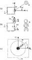
레이저 레이더를 거리 측정장치로서 이용하는 경우의 좌표간 관계에 대해서 설명한다. 도 21의 (a) 및 도 21의 (b)는 자율 이동로봇(1)에서의 좌표의 배치를 나타낸다. 자율 이동로봇(1)에 고정된 좌표인 기준좌표계(XR-YR)는 직교좌표계이며, 레이저 레이더(83)의 스캔 중심에 원점을 갖는 좌표계(XS-YS)도 직교좌표계이다. XR-YR 평면과 XS-YS 평면은 동일 평면 내에 있고, XR축과 XS축은 동일 방향에 있고, YR축과 YS축은, 거리 dS만큼 어긋나 있다. 레이저 레이더(83)의 스캔 중심으로부터 거리 D3, 방향각 β의 위치에 있는 XS-YS 평면 내의 물체 O3의 위치좌표는, 좌표계 XS-YS에 있어서,The relationship between coordinates when using a laser radar as a distance measuring apparatus is demonstrated. 21 (a) and 21 (b) show the arrangement of coordinates in the autonomous
XS = D3×sin(β)XS = D3 × sin (β)
YS = 1D3×cos(β)이 되고, 좌표계 XR-YR에 있어서,YS = 1D3 x cos (β), and in the coordinate system XR-YR,
XR = XS + dSXR = XS + dS
YR = YS가 된다.YR = YS.
정규화 화상좌표계와 자율 이동로봇의 기준좌표계와의 관계에 대해서 설명한다. 도 22는 자율 이동로봇(1)의 기준좌표계와 정규화 화상좌표계와의 관계를 나타낸다. 거리정보 취득수단에서 얻어지는 3차원 공간 중의 점 M1이, 정규화 화상 위의 점 m1로서 관측되는 경우, 자율 이동로봇(1)의 기준좌표계, 카메라 좌표계, 디지털 화상좌표계, 정규화 화상좌표계에 있어서 관측 위치가 표현된다. 자율 이동로봇(1)의 기준좌표계에서의 점 M1의 좌표를 (XR, YR, ZR)이라 하고, 정규화 화상좌표계에서의 점 m1의 좌표를 (u, v)이라 하면, 점 M1의 좌표보다 점 m1의 좌표는 식(8)을 이용해서 계산된다.The relationship between the normalized image coordinate system and the reference coordinate system of an autonomous mobile robot will be described. 22 shows the relationship between the reference coordinate system and the normalized image coordinate system of the autonomous

이러한 변환을 이용해서 레이저 레이더 계측결과를 화상 위에 투영할 수 있다. 위의 식에 있어서, S는 정수, f는 촛점거리, ku, kv는 정규화 화상좌표를 기준으로 했을 때의 u, v축의 단위, uO, vO는 디지털 화상좌표계에서의 정규화 화상좌표원점의 좌표, θ는 u축과 v축이 이루는 각도, r11 등은 자율 이동로봇(1)의 기준좌표계와 카메라 좌표계간의 회전 행렬, t1, t2, t3은 자율 이동로봇(1)의 기준좌표계와 카메라 좌표계간의 병진 행렬을 나타낸다. 이들의 파라미터는, 미리 카메라 캘리브레이션(calibration)을 행하는 것에 의해 구해진다. 이 식(8)의 도출은 기본 적인 것이며, 예컨대,「컴퓨터 비전 기술평론과 장래 전망」(신기술 커뮤니케이션즈)의 제6장 컴퓨터 비전에서의 에피폴라(epipolar) 기하(幾何)에 도출 예가 있다.This conversion can be used to project the laser radar measurement results onto the image. In the above equation, S is an integer, f is the focal length, ku, kv is the unit of u and v-axis, uO and vO are the coordinates of the normalized image coordinate origin in the digital image coordinate system. θ is the angle formed by the u-axis and v-axis, r11 is the rotation matrix between the reference coordinate system of the autonomous
(레이저 레이더 계측결과에 근거하는 화상처리)(Image processing based on laser radar measurement results)
거리정보 취득수단(8)의 계측결과를 참조해서, 화상정보 취득수단(7)에 있어서 사람 인식을 행하고, 환경을 인식하는 예에 대해서 설명한다. 이 예에서는, 거리정보 취득수단(8)에서의 거리 측정장치(81)로서 레이저 레이더(83)를 사용한다.레이저 레이더(83)에 의해 거리 계측을 행하고, 거리정보 해석수단(82)이, 그 계측 데이터로부터 사람의 크기에 대응하는 폭의 물체를 검출한 경우, 그 물체를 사람 후보라고 한다. 화상정보 취득수단(7)은, 그 사람 후보 위치에 대응하는 화상 중에 있어서 사람 인식을 한다.With reference to the measurement result of the distance information acquisition means 8, the example which performs a person recognition in the image information acquisition means 7, and recognizes an environment is demonstrated. In this example, the
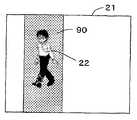
도 23은 레이저 레이더 계측결과를 참조해서 인식 처리되는 화상을 나타내고, 도 24는 레이저 레이더 계측결과를 참조해서 사람 후보 검출을 행하는 처리 플로우를 나타낸다. 레이저 레이더로 물체거리가 계측되고(S501), 거리정보 해석수단(82)은 거리 계측 데이터에서 사람 후보를 탐색한다(S502).사람 후보가 존재하지 않을 경우(S503에서 N), 사람은 존재하지 않는다는 결과를 환경 인식수단(9)에 출력하고(S504), 사람 후보가 존재하는 경우(S503에서 Y), 그 위치가 레이저 레이더 좌표계로부터 자율 이동로봇의 기준좌표계로 변환된다(S505).FIG. 23 shows an image to be processed for recognition with reference to the laser radar measurement results, and FIG. 24 shows a processing flow for detecting a human candidate with reference to the laser radar measurement results. The object distance is measured by the laser radar (S501), and the distance information analyzing means 82 searches for the person candidate in the distance measurement data (S502). If no person candidate exists (N in S503), no person exists. If not, the result is output to the environmental recognition means 9 (S504), and if a human candidate exists (Y in S503), the position is converted from the laser radar coordinate system to the reference coordinate system of the autonomous mobile robot (S505).
계속해서, 전술의 식(8)을 이용하여, 사람 후보의 위치를, 자율 이동로봇의 기준좌표계로부터 정규화 화상좌표계로 변환하여(S506), 정규화 화상좌표상에서의 위치가 구해지며, 도 23에 나타나는 바와 같이, 화상(21) 위에 투영된 사람 후보 위치(22)의 주변에, 검출 대상으로 하는 사람의 크기에 대응해서 미리 결정해 둔 사람 검출 에리어(90)가 설정된다(S507). 환경 인식수단(9)은, 사람 검출 에리어(90)내에서 사람 검출 처리를 행해(S508), 사람 후보를 검출하면 레이저 레이더로 검출된 사람 후보는 사람이었다고 판정하고(S509에서 Y), 레이저 레이더로부터의 검출 결과는 정확하게 사람을 검출한 것으로 해서, 그 신호를 주행 제어수단(4)에 출력한다(S510). 이상의 처리가 모든 사람 후보에 대해서 행하여진다(S511). 이렇게, 레이저 레이더의 계측결과에 근거하여, 화상처리에 의한 사람 검출처리를 행하는 에리어를 제한하는 것에 의해, 처리 효율을 높인 사람 검출의 신뢰성을 향상시킬 수 있다.Subsequently, the position of the human candidate is converted into the normalized image coordinate system from the reference coordinate system of the autonomous mobile robot by using the above formula (8) (S506), and the position on the normalized image coordinate is obtained, which is shown in FIG. As described above, in the vicinity of the
(화상처리 결과에 근거하는 레이저 레이더 계측)(Laser radar measurement based on image processing result)
이하는 상기와는 다른 예로서, 화상정보 취득수단(7)의 처리 결과를 참조하여, 거리정보 취득수단(8)에 있어서 사람 후보의 거리정보를 취득하고, 환경을 인식하는 예에 대해서 설명한다. 도 25의 (a) 및 도 25의 (b)는 화상처리 결과에 근거한 레이저 레이더 계측을 나타내고, 도 25의 (c)는 계측결과의 화상을 나타낸다. 도 26은 화상처리 결과를 참조해서 레이저 레이더 계측에 의한 사람 검출의 처리 플로우를 나타낸다. 이 예에서는, 화상정보 취득수단(7)에서의 촬상장치(71)에는 전(全)방향 카메라(74)를, 거리정보 취득수단(8)에서의 거리 측정장치(81)에는 레이저 레이더(83)가 이용된다. 도면에 나타내는 바와 같이, 전방향 카메라(74)의 카메라 좌표계(XC-YC-ZC)와, 레이저 레이더의 좌표계(XL-YL-ZL)는, 각 축의 방향이 일치하고 있다. 카메라 좌표계의 원점은, 레이저 레이더 좌표계의 ZL축 위를 상방 으로 시프트 한 위치가 되도록, 전방향 카메라(74)가 설치되어 있다.As an example different from the above, an example in which the distance information acquisition means 8 acquires the distance information of the person candidate and the environment is recognized will be described with reference to the processing result of the image information acquisition means 7. . 25 (a) and 25 (b) show laser radar measurement based on the image processing result, and FIG. 25 (c) shows an image of the measurement result. Fig. 26 shows a processing flow of person detection by laser radar measurement with reference to the image processing result. In this example, the
우선, 전방향 카메라(74)에 의해 취득된 전방위 화상(19)에 대해서, 화상인식 처리수단(72)에 의해 사람 후보의 검출이 행하여진다(S601). 사람 후보가 존재하지 않는 경우(S602에서 N), 사람은 존재하지 않는다는 결과가 환경 인식수단(9)에 출력되고(S603), 사람 후보가 존재하는 경우(S602에서 Y), 검출된 사람 후보의 두부위치 방향과 카메라 좌표의 XC축의 이루는 각도 Φ가 계산된다(604). 다음에, 레이저 레이더(83)에 의해, 레이저 레이더 좌표의 XL축으로부터 각도 Φ의 방향의 각도 주변이 계측되고(S605), 거리정보 해석수단(82)과 환경 인식수단(9)에 의해, 사람의 크기에 대응하는 폭의 물체의 탐색이 행하여져(S606), 사람 후보가 검출되면(S607에서 Y), 사람을 검출했다고 해서 주행 제어수단(4)에 결과가 출력된다(S609). 이상의 처리가, 화상을 처리해서 얻어진 모든 사람 후보에 대해서 행하여진다(S609).First, with respect to the
(사람을 자율 이동로봇이 알아차리고 있는가 아닌가의 판단 처리)(Determination of whether the autonomous mobile robot is aware of the person)
사람을 자율 이동로봇이 알아차리고 있는가 아닌가의 판단 방법에 대해서 설명한다. 도 27의 (a)는 사람을 동 장치가 알아차리고 있는 화상을 나타내고, 도 27의 (b)는 알아차리고 있지 않는다는 화상을 나타내며, 도 28은 사람까지의 거리와 얼굴의 살색면적의 관계 그래프를 나타낸다. 화상인식 처리수단(72)에 있어서, 거리정보 취득수단(8)의 정보에 근거해서 사람 인식이 행하여진 후, 그 사람을, 자율 이동로봇(1)이 알아차리고 있는가 아닌가의 판단이 화상인식 처리수단(72)에 의해 행하여진다. 화상인식 처리수단(72)은, 적어도 촬상한 화상으로부터 살색영역을 검출하는 살색영역 검출부와, 검출된 살색영역의 형상에 대해서 연산 처리하는 형상 특징처리부를 포함하고 있고, 검출된 살색영역이 미리 결정한 형상 특징 조건을 충족할 때, 화상인식 처리수단(72)은, 그 살색영역을 사람의 후보로서 인식한다.Explain how to judge whether a robot is aware of a person. FIG. 27A shows an image in which the device is aware of a person, and FIG. 27B shows an image in which the device is not aware. FIG. 28 shows a graph of the relationship between the distance to the person and the skin color area of the face. Indicates. In the image recognition processing means 72, after the person recognition is performed based on the information of the distance
그리고, 사람이 자율 이동로봇에 대해서 정면을 향하고 있는 정도, 알아차림 정도가 높고, 반대로, 옆을 향하고 있는 정도, 알아차림 정도가 낮다는 것으로서 알아차림 정도가 판정된다. 또한, 자립 이동장치에 대한 얼굴의 방향 상태는, 두부영역에서의 살색영역 면적의 크기로 행하여진다. 도 27에 나타내는 바와 같이, 일반적으로, 정면을 향할수록 살색면적이 증가한다. 또한, 사람의 두부의 크기는, 개인차에 의하지 않고 어떤 일정한 크기를 가정할 수 있다. 따라서, 도 28에 나타내는 바와 같이, 정면을 향한 표준 얼굴의 살색면적(Si)은, 자율 이동로봇으로부터 사람까지의 거리(Di)의 함수로서 나타낼 수 있다. 이 자율 이동로봇으로부터 사람까지의 거리(Di)와 얼굴의 표준 살색면적(Si)의 관계는, 실험에 의해 미리 구해 둘 수 있다.Then, the degree of awareness is determined as the degree to which the person faces the autonomous mobile robot toward the front, the degree of awareness is high, and conversely, the degree to the side and the degree of awareness is low. In addition, the direction of the face with respect to the self-supporting moving device is performed in the size of the skin area in the head region. As shown in FIG. 27, generally, the flesh area increases as it goes to the front. In addition, the size of the head of a person can be assumed to be a certain size regardless of individual differences. Therefore, as shown in FIG. 28, the flesh-colored area Si of the standard face facing front can be represented as a function of the distance Di from an autonomous mobile robot to a person. The relationship between the distance Di from the autonomous mobile robot to the person and the standard flesh area Si of the face can be determined in advance by experiment.
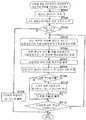
사람을 자율 이동로봇이 알아차리고 있는가 아닌가의 판단처리를 포함하는 처리 플로우에 대해서 설명한다. 도 29는 사람 검출처리 플로우를 나타낸다. 이 예에서는, 거리정보 취득수단(8)의 거리 측정장치(81)로서 레이저 레이더(83)를 이용하고, 화상정보 취득수단(7)의 촬상장치(71)로서 고정 카메라(70)를 이용한 경우에 대해서 설명한다. 이 처리 플로우에서의 스텝 S701~S709은, 전출의 도 24에서의 레이저 레이더 계측결과에 의한 화상처리 플로우의 스텝 S501~S509과 동일하여, 설명은 생략한다. 스텝 S709에 있어서, 사람 후보가 검출된 경우(S509에서 Y), 그 검출 된 사람을 자율 이동로봇이 알아차리고 있는가의 처리가 행하여지고(S710), 그 후, 사람의 검출 출력에 사람을 자율 이동로봇이 알아차리고 있는가 아닌가 판정되어서, 그 판정 결과를 나타내는 속성과, 레이저 레이더로 검출된 사람 후보는 사람이었다는 판정 결과가 환경 인식수단(9)에 출력된다(S711). 이상의 처리가 모든 사람 후보에 대해서 행하여진다(S712).A processing flow including determination processing of whether the autonomous mobile robot is aware of a person will be described. 29 shows a human detection processing flow. In this example, when the
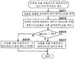
상술의 스텝 S710에서, 검출된 사람을 자율 이동로봇이 알아차리고 있는가 아닌가의 판정 처리의 상세를 설명한다. 도 30은 사람을 자율 이동로봇이 알아차리고 있는가 아닌가의 판단 처리 플로우를 나타낸다. 화상인식 처리수단(72)에 있어서, 사람을 검출한 살색영역(24)의 면적(smi)이, 예컨대 화소수에 의해 계측된다(S801). 다음에, 레이저 레이더에 의한 사람의 계측 거리(di) 및 자율 이동로봇으로부터 사람까지의 거리와 정면을 향한 사람의 얼굴의 살색면적과의 관계(도 28)를 사용해서, 표준 살색면적(si)이 구해진다(S802). 다음에, 살색영역내의 면적(smi)과 표준 살색면적(si)과의 비(比) smi/si가 구해져 미리 결정된 문턱치(TH)와 비교된다(S803). 비교의 결과, smi/si>TH이라면(S803에서 Y), 사람을 자율 이동로봇이 알아차리고 있다고 판정되며(S804), smi/si<TH이라면(S803에서 N), 사람을 자율 이동로봇이 알아차리고 있지 않다고 판정된다(S805).In the above-described step S710, the details of the determination processing of whether the autonomous mobile robot is aware of the detected person will be described. Fig. 30 shows a process for determining whether an autonomous mobile robot is aware of a person. In the image recognition processing means 72, the area smi of the flesh-
또, 본 발명은, 상기 구성에 한정되지 않고 여러 가지 변형이 가능하다. 예컨대, 도 31의 (a), 도 31의 (b), 도 31의 (c)에 나타나는 바와 같이, 촬상장치와 거리 측정장치를 조합시킬 수 있다. 도 31의 (a)의 자율 이동로봇(1)은, 1개의 레이저 레이더(83)와 회전기구(70a) 상의 2개의 카메라(70)를 구비하고 있고, 도 31 의 (b)의 자율 이동로봇(1)은, 2개의 레이저 레이더(83)와 회전기구(70a) 상의 2개의 카메라(70)를 구비하고 있으며, 도 31의 (c)의 자율 이동로봇(1)은, 1개의 레이저 레이더(83)와 1세트의 초음파 센서(84) 및 회전기구(70a) 상의 2개의 카메라(70)를 구비하고 있다.In addition, this invention is not limited to the said structure, A various deformation | transformation is possible. For example, as shown in Figs. 31A, 31B, and 31C, the imaging device and the distance measuring device can be combined. The autonomous
또, 본 출원은, 2003년 3월 14일자의 특허출원에 근거해서 우선권 주장을 한다. 그 출원의 내용 전체가 참조에 의해, 이 출원에 편입된다.In addition, this application claims priority based on the March 14, 2003, patent application. The entire contents of the application are incorporated in this application by reference.
Claims (15)
Translated fromKoreanApplications Claiming Priority (2)
| Application Number | Priority Date | Filing Date | Title |
|---|---|---|---|
| JP2003070728AJP3879848B2 (en) | 2003-03-14 | 2003-03-14 | Autonomous mobile device |
| JPJP-P-2003-00070728 | 2003-03-14 |
Publications (2)
| Publication Number | Publication Date |
|---|---|
| KR20050108396A KR20050108396A (en) | 2005-11-16 |
| KR100773184B1true KR100773184B1 (en) | 2007-11-02 |
Family
ID=32984667
Family Applications (1)
| Application Number | Title | Priority Date | Filing Date |
|---|---|---|---|
| KR1020057017184AExpired - Fee RelatedKR100773184B1 (en) | 2003-03-14 | 2004-03-12 | Autonomously moving robot |
Country Status (6)
| Country | Link |
|---|---|
| US (1) | US7684894B2 (en) |
| JP (1) | JP3879848B2 (en) |
| KR (1) | KR100773184B1 (en) |
| DE (1) | DE112004000438T5 (en) |
| TW (1) | TWI242701B (en) |
| WO (1) | WO2004081683A1 (en) |
Cited By (6)
| Publication number | Priority date | Publication date | Assignee | Title |
|---|---|---|---|---|
| KR101049155B1 (en)* | 2011-02-01 | 2011-07-14 | 국방과학연구소 | Obstacle judgment method of autonomous mobile device and autonomous mobile device using same |
| KR101415297B1 (en) | 2008-04-16 | 2014-07-07 | 삼성전자주식회사 | Robot Map Generation Method, Robot Map Usage Method, and Robot Having Robot Map |
| KR20180098040A (en)* | 2017-02-24 | 2018-09-03 | 엘지전자 주식회사 | Moving robot and control method thereof |
| WO2022102967A1 (en)* | 2020-11-11 | 2022-05-19 | 삼성전자주식회사 | Electronic apparatus and controlling method thereof |
| US12140954B2 (en) | 2018-09-20 | 2024-11-12 | Samsung Electronics Co., Ltd. | Cleaning robot and method for performing task thereof |
| US12233555B2 (en) | 2018-09-20 | 2025-02-25 | Samsung Electronics Co., Ltd. | Cleaning robot and task performing method therefor |
Families Citing this family (116)
| Publication number | Priority date | Publication date | Assignee | Title |
|---|---|---|---|---|
| JP4595436B2 (en)* | 2004-03-25 | 2010-12-08 | 日本電気株式会社 | Robot, control method thereof and control program |
| JP4564447B2 (en)* | 2004-12-14 | 2010-10-20 | 本田技研工業株式会社 | Autonomous mobile robot |
| US7742841B2 (en)* | 2005-02-23 | 2010-06-22 | Panasonic Electric Works Co., Ltd. | Autonomous vehicle and planar obstacle recognition method |
| JP4093261B2 (en)* | 2005-03-15 | 2008-06-04 | 松下電工株式会社 | Autonomous mobile device |
| JP4882275B2 (en)* | 2005-05-18 | 2012-02-22 | パナソニック電工株式会社 | Autonomous mobile robot and its movement status recording system |
| US7783382B2 (en)* | 2006-02-24 | 2010-08-24 | Qisda Corporation | Controlling machine actions based on luminance of environmental light and distance from user |
| KR100772907B1 (en)* | 2006-05-01 | 2007-11-05 | 삼성전자주식회사 | Robot with Obstacle Sensing Function and its Control Method |
| JP4970861B2 (en)* | 2006-07-07 | 2012-07-11 | 本田技研工業株式会社 | Vehicle periphery monitoring system, vehicle, vehicle periphery monitoring program, and vehicle periphery monitoring system construction system |
| KR100966875B1 (en)* | 2006-09-26 | 2010-06-29 | 삼성전자주식회사 | Robot positioning using omnidirectional image |
| JP4314266B2 (en)* | 2006-11-22 | 2009-08-12 | キヤノン株式会社 | Image control apparatus and control method thereof |
| JP4528295B2 (en)* | 2006-12-18 | 2010-08-18 | 株式会社日立製作所 | GUIDANCE ROBOT DEVICE AND GUIDANCE SYSTEM |
| JP4871160B2 (en)* | 2007-02-16 | 2012-02-08 | 株式会社東芝 | Robot and control method thereof |
| JP4953313B2 (en)* | 2007-09-10 | 2012-06-13 | 公立大学法人首都大学東京 | Environment recognition system, autonomous mobile body and environment recognition program |
| KR100884904B1 (en)* | 2007-09-12 | 2009-02-19 | 아주대학교산학협력단 | Magnetic Position Recognition Using Parallel Projection Model |
| JP5085251B2 (en)* | 2007-09-25 | 2012-11-28 | パナソニック株式会社 | Autonomous mobile device |
| US8838268B2 (en)* | 2008-01-28 | 2014-09-16 | Seegrid Corporation | Service robot and method of operating same |
| JP4978494B2 (en)* | 2008-02-07 | 2012-07-18 | トヨタ自動車株式会社 | Autonomous mobile body and control method thereof |
| JP4670899B2 (en)* | 2008-05-22 | 2011-04-13 | 村田機械株式会社 | Traveling car |
| KR101556593B1 (en)* | 2008-07-15 | 2015-10-02 | 삼성전자주식회사 | Image processing method |
| TWM348676U (en)* | 2008-07-22 | 2009-01-11 | Iner Aec Executive Yuan | Environmental survey robot |
| TWI408397B (en)* | 2008-08-15 | 2013-09-11 | Univ Nat Chiao Tung | Automatic navigation device with ultrasonic and computer vision detection and its navigation method |
| WO2010021090A1 (en)* | 2008-08-20 | 2010-02-25 | パナソニック株式会社 | Distance estimating device, distance estimating method, program, integrated circuit, and camera |
| KR101202695B1 (en)* | 2008-10-01 | 2012-11-19 | 무라다기카이가부시끼가이샤 | Autonomous movement device |
| TWI396830B (en)* | 2008-11-28 | 2013-05-21 | Univ Nat Taiwan | Patrol device and patrol path planning method for the same |
| KR101006211B1 (en)* | 2008-12-01 | 2011-01-07 | 한국기술교육대학교 산학협력단 | Method of Extending Sensing Range of Moving Object with Sensor |
| TWI388956B (en) | 2009-05-20 | 2013-03-11 | Univ Nat Taiwan Science Tech | Mobile robot, method for planning paths of manipulating target objects thereof |
| GB0919158D0 (en)* | 2009-11-02 | 2009-12-16 | Onslow Leigh M The Viscountess | Multi-function monitor |
| EP2506106B1 (en) | 2009-11-27 | 2019-03-20 | Toyota Jidosha Kabushiki Kaisha | Autonomous moving object and control method |
| TWI394933B (en)* | 2010-01-28 | 2013-05-01 | Univ Nat Kaohsiung Applied Sci | Image path planning guidance system |
| JP5560978B2 (en)* | 2010-07-13 | 2014-07-30 | 村田機械株式会社 | Autonomous mobile |
| TWI409605B (en)* | 2010-07-14 | 2013-09-21 | Qisda Corp | Electronic apparatus capable of automatic location and moving, and automatic homing method for moving element thereof |
| JP5621483B2 (en)* | 2010-10-05 | 2014-11-12 | トヨタ自動車株式会社 | Robot and control method thereof |
| US8965579B2 (en) | 2011-01-28 | 2015-02-24 | Intouch Technologies | Interfacing with a mobile telepresence robot |
| US9323250B2 (en) | 2011-01-28 | 2016-04-26 | Intouch Technologies, Inc. | Time-dependent navigation of telepresence robots |
| US9098611B2 (en) | 2012-11-26 | 2015-08-04 | Intouch Technologies, Inc. | Enhanced video interaction for a user interface of a telepresence network |
| US20140139616A1 (en) | 2012-01-27 | 2014-05-22 | Intouch Technologies, Inc. | Enhanced Diagnostics for a Telepresence Robot |
| US9259842B2 (en) | 2011-06-10 | 2016-02-16 | Microsoft Technology Licensing, Llc | Interactive robot initialization |
| US8761933B2 (en)* | 2011-08-02 | 2014-06-24 | Microsoft Corporation | Finding a called party |
| US8972055B1 (en)* | 2011-08-19 | 2015-03-03 | Google Inc. | Methods and systems for selecting a velocity profile for controlling a robotic device |
| JP5442050B2 (en)* | 2012-02-15 | 2014-03-12 | 本田技研工業株式会社 | Vehicle perimeter monitoring system |
| KR101272604B1 (en)* | 2012-04-25 | 2013-06-07 | 주식회사 유진로봇 | Riding robot and operating system comprising the same |
| US9361021B2 (en) | 2012-05-22 | 2016-06-07 | Irobot Corporation | Graphical user interfaces including touchpad driving interfaces for telemedicine devices |
| WO2013176760A1 (en) | 2012-05-22 | 2013-11-28 | Intouch Technologies, Inc. | Graphical user interfaces including touchpad driving interfaces for telemedicine devices |
| JP5314788B2 (en)* | 2012-06-11 | 2013-10-16 | パナソニック株式会社 | Autonomous mobile device |
| US9321173B2 (en) | 2012-06-22 | 2016-04-26 | Microsoft Technology Licensing, Llc | Tracking and following people with a mobile robotic device |
| US9186793B1 (en)* | 2012-08-31 | 2015-11-17 | Brain Corporation | Apparatus and methods for controlling attention of a robot |
| TWI459170B (en)* | 2012-10-04 | 2014-11-01 | Ind Tech Res Inst | A moving control device and an automatic guided vehicle with the same |
| JP5597322B1 (en)* | 2012-11-05 | 2014-10-01 | パナソニック株式会社 | RUNNING INFORMATION GENERATION DEVICE, METHOD, AND PROGRAM FOR AUTONOMOUS TRAVEL DEVICE |
| JP6123370B2 (en)* | 2013-03-12 | 2017-05-10 | 株式会社豊田中央研究所 | Autonomous mobile device that moves by measuring the distance to the obstacle |
| US9517175B1 (en)* | 2013-03-14 | 2016-12-13 | Toyota Jidosha Kabushiki Kaisha | Tactile belt system for providing navigation guidance |
| JP5672327B2 (en)* | 2013-03-19 | 2015-02-18 | 株式会社安川電機 | Robot system |
| JP5976198B2 (en)* | 2013-03-26 | 2016-08-23 | 株式会社日立国際電気 | Number counting device and number counting method |
| JP2014197294A (en) | 2013-03-29 | 2014-10-16 | 株式会社日立産機システム | Position identification device and mobile robot having the same |
| JP2015019689A (en)* | 2013-07-16 | 2015-02-02 | アルプス電気株式会社 | Obstacle detection device and detection method thereof |
| KR102085180B1 (en)* | 2013-10-08 | 2020-03-05 | 삼성전자주식회사 | Method of estimating body's orientation, Computer readable storage medium of recording the method and an device |
| US20150142251A1 (en)* | 2013-11-21 | 2015-05-21 | International Business Machines Corporation | Vehicle control based on colors representative of navigation information |
| US9532031B1 (en)* | 2014-04-08 | 2016-12-27 | The United States Of America As Represented By The Secretary Of The Navy | Method for extrinsic camera calibration using a laser beam |
| US10735902B1 (en)* | 2014-04-09 | 2020-08-04 | Accuware, Inc. | Method and computer program for taking action based on determined movement path of mobile devices |
| JP6599603B2 (en)* | 2014-04-18 | 2019-10-30 | 東芝ライフスタイル株式会社 | Autonomous vehicle |
| WO2016009688A1 (en)* | 2014-07-16 | 2016-01-21 | 株式会社リコー | System, machine, control method, and program |
| CN104216411B (en)* | 2014-09-27 | 2016-11-09 | 江阴润玛电子材料股份有限公司 | A kind of patrolling method in electronic circuit |
| US9434069B1 (en) | 2014-11-10 | 2016-09-06 | Google Inc. | Motion heat map |
| KR101681187B1 (en)* | 2015-01-21 | 2016-12-01 | 한국과학기술연구원 | Localization system and method of robot |
| US9880263B2 (en)* | 2015-04-06 | 2018-01-30 | Waymo Llc | Long range steerable LIDAR system |
| JP6528280B2 (en)* | 2015-12-28 | 2019-06-12 | 株式会社エクォス・リサーチ | Moving body |
| JP2016064829A (en)* | 2015-12-28 | 2016-04-28 | エイディシーテクノロジー株式会社 | Vehicle control device |
| CN107836013B (en)* | 2016-03-09 | 2019-09-03 | 广州艾若博机器人科技有限公司 | Map constructing method, correction method and device |
| WO2017159680A1 (en)* | 2016-03-17 | 2017-09-21 | 日本電気株式会社 | Searh support apparatus, search support system, search support method, and program recording medium |
| CN106092091B (en)* | 2016-08-10 | 2019-07-02 | 京东方科技集团股份有限公司 | Electronic machinery and equipment |
| CN107356929B (en)* | 2016-08-29 | 2020-07-28 | 北醒(北京)光子科技有限公司 | Rapid scanning detection method |
| EP4194887A1 (en)* | 2016-09-20 | 2023-06-14 | Innoviz Technologies Ltd. | Lidar systems and methods |
| JP7074066B2 (en)* | 2016-11-14 | 2022-05-24 | ソニーグループ株式会社 | Information processing equipment, information processing methods, recording media, and programs |
| JP6938969B2 (en)* | 2017-03-07 | 2021-09-22 | 富士フイルムビジネスイノベーション株式会社 | Environmental measurement systems and programs |
| JP2018146440A (en)* | 2017-03-07 | 2018-09-20 | 株式会社豊田自動織機 | Environment recognition device |
| JP6776960B2 (en)* | 2017-03-14 | 2020-10-28 | トヨタ自動車株式会社 | Autonomous mobile |
| WO2018173595A1 (en)* | 2017-03-22 | 2018-09-27 | 日本電産株式会社 | Movement device |
| JP6830656B2 (en)* | 2017-03-30 | 2021-02-17 | 株式会社エクォス・リサーチ | Object determination device and object determination program |
| KR20180134230A (en)* | 2017-06-08 | 2018-12-18 | 삼성전자주식회사 | Cleaning robot and controlling method of thereof |
| KR102391914B1 (en)* | 2017-06-30 | 2022-04-27 | 엘지전자 주식회사 | Method for operating moving robot |
| CN107463175A (en)* | 2017-08-04 | 2017-12-12 | 河南工程学院 | Automatic obstacle avoidance trolley, barrier-avoiding method and system |
| US10523880B2 (en)* | 2017-09-28 | 2019-12-31 | Waymo Llc | Synchronized spinning LIDAR and rolling shutter camera system |
| US10936886B2 (en) | 2017-12-29 | 2021-03-02 | PlusAI Corp | Method and system for stereo based vehicle pose estimation |
| JP7060231B2 (en)* | 2018-02-06 | 2022-04-26 | 株式会社Soken | Mobile control device |
| WO2019167210A1 (en)* | 2018-02-28 | 2019-09-06 | 本田技研工業株式会社 | Control device, mobile body, and program |
| JP6894595B2 (en)* | 2018-03-28 | 2021-06-30 | 株式会社エクォス・リサーチ | Mobile |
| JP6788915B2 (en)* | 2018-06-21 | 2020-11-25 | クモノスコーポレーション株式会社 | 3D laser scanner, 3D laser scanner system, construction work machine and construction method |
| JPWO2020049850A1 (en) | 2018-09-04 | 2021-09-24 | ソニーグループ株式会社 | Information processing equipment, information processing methods, programs, and mobile devices |
| US20200086497A1 (en)* | 2018-09-13 | 2020-03-19 | The Charles Stark Draper Laboratory, Inc. | Stopping Robot Motion Based On Sound Cues |
| JP6559864B1 (en)* | 2018-10-04 | 2019-08-14 | 関西電力株式会社 | Travel control device, travel control method, and automatic travel vehicle |
| TWI721324B (en)* | 2018-10-10 | 2021-03-11 | 鴻海精密工業股份有限公司 | Electronic device and stereoscopic object determining method |
| JP2020071182A (en)* | 2018-11-01 | 2020-05-07 | パナソニックIpマネジメント株式会社 | Driving support device, vehicle and driving support method |
| WO2020145095A1 (en)* | 2019-01-10 | 2020-07-16 | 株式会社小糸製作所 | LiDAR SENSOR UNIT AND VEHICLE SECURITY SYSTEM |
| US11338438B2 (en)* | 2019-01-25 | 2022-05-24 | Bear Robotics, Inc. | Method, system and non-transitory computer-readable recording medium for determining a movement path of a robot |
| JP2022519788A (en) | 2019-02-11 | 2022-03-24 | 643エーアイ リミテッド | Systems and methods for managing multiple autonomous vehicles |
| US11597104B2 (en) | 2019-07-31 | 2023-03-07 | X Development Llc | Mobile robot sensor configuration |
| JP2021056764A (en)* | 2019-09-30 | 2021-04-08 | 日本電産株式会社 | Movable body |
| JP7408334B2 (en)* | 2019-10-03 | 2024-01-05 | Thk株式会社 | Image processing device and mobile object control system |
| JPWO2021152340A1 (en)* | 2020-01-31 | 2021-08-05 | ||
| WO2021166637A1 (en)* | 2020-02-17 | 2021-08-26 | ソニーグループ株式会社 | Transport robot, control method, program, and control device |
| JP7404137B2 (en)* | 2020-04-01 | 2023-12-25 | 株式会社豊田中央研究所 | Facial image processing device and facial image processing program |
| CN111714034B (en) | 2020-05-18 | 2022-10-21 | 科沃斯机器人股份有限公司 | Control method and system of self-moving robot and self-moving robot |
| WO2021252425A1 (en)* | 2020-06-08 | 2021-12-16 | Brain Corporation | Systems and methods for wire detection and avoidance of the same by robots |
| US11767037B2 (en) | 2020-09-22 | 2023-09-26 | Argo AI, LLC | Enhanced obstacle detection |
| CN112526984B (en)* | 2020-09-30 | 2024-06-21 | 深圳银星智能集团股份有限公司 | Robot obstacle avoidance method and device and robot |
| CN112232272B (en)* | 2020-11-02 | 2023-09-08 | 上海有个机器人有限公司 | Pedestrian recognition method by fusing laser and visual image sensor |
| JP7521442B2 (en)* | 2021-02-01 | 2024-07-24 | トヨタ自動車株式会社 | AUTONOMOUS MOBILITY SYSTEM, AUTONOMOUS MOBILITY METHOD, AND AUTONOMOUS MOBILITY PROGRAM |
| JP7404282B2 (en)* | 2021-02-10 | 2023-12-25 | 株式会社豊田中央研究所 | Facial model parameter estimation device, facial model parameter estimation method, and facial model parameter estimation program |
| CN113110481B (en)* | 2021-04-26 | 2024-02-06 | 上海智蕙林医疗科技有限公司 | Emergency avoidance implementation method, system, robot and storage medium |
| CN114374777B (en)* | 2021-06-02 | 2023-06-16 | 北京石头世纪科技股份有限公司 | Linear laser module and self-moving equipment |
| CN113433560B (en)* | 2021-06-25 | 2023-12-26 | 北京铁道工程机电技术研究所股份有限公司 | Positioning method and device for robot side inspection, electronic equipment and medium |
| CN113610910B (en)* | 2021-07-30 | 2024-04-09 | 合肥科大智能机器人技术有限公司 | Obstacle avoidance method for mobile robot |
| KR20230039421A (en)* | 2021-09-14 | 2023-03-21 | 삼성전자주식회사 | Electronic device and Method for controlling the electronic device thereof |
| TWI769924B (en)* | 2021-09-15 | 2022-07-01 | 東元電機股份有限公司 | System for following human |
| KR102425271B1 (en) | 2021-12-29 | 2022-07-27 | 주식회사 파이엇 | a method of n autonomous mobile robot with obstacle avoidance method |
| KR102654371B1 (en)* | 2022-02-07 | 2024-04-02 | 백수빈 | Unmanned ground reconnaissance apparatus for automatic driving |
| JP7720894B2 (en)* | 2023-11-14 | 2025-08-08 | 本田技研工業株式会社 | Control device, control method, and program |
Citations (3)
| Publication number | Priority date | Publication date | Assignee | Title |
|---|---|---|---|---|
| JPH02259912A (en)* | 1989-03-31 | 1990-10-22 | Glory Ltd | Self normal positioning method for mobile object |
| JPH11104984A (en)* | 1997-10-06 | 1999-04-20 | Fujitsu Ltd | REAL ENVIRONMENT INFORMATION DISPLAY AND COMPUTER-READABLE RECORDING MEDIUM CONTAINING PROGRAM FOR EXECUTING REAL ENVIRONMENT INFORMATION DISPLAY PROCESS |
| JPH11198075A (en)* | 1998-01-08 | 1999-07-27 | Mitsubishi Electric Corp | Behavior support device |
Family Cites Families (21)
| Publication number | Priority date | Publication date | Assignee | Title |
|---|---|---|---|---|
| JPS6371604A (en)* | 1986-09-12 | 1988-04-01 | Hideo Mori | System for detecting road boarder and obstacle by using area-divided color image |
| JPS63124114A (en)* | 1986-11-14 | 1988-05-27 | Hitachi Ltd | Recognizing device for environment of traveling object |
| JPS63213005A (en)* | 1987-03-02 | 1988-09-05 | Hitachi Ltd | Moving object guidance method |
| JPH036710A (en)* | 1989-06-05 | 1991-01-14 | Toshiba Corp | Tracking mobile robot control device |
| JPH0412218A (en)* | 1990-05-01 | 1992-01-16 | Toyota Motor Corp | Distance detecting device for vehicle |
| JP3263699B2 (en) | 1992-12-22 | 2002-03-04 | 三菱電機株式会社 | Driving environment monitoring device |
| JP2501010B2 (en) | 1993-10-25 | 1996-05-29 | インターナショナル・ビジネス・マシーンズ・コーポレイション | Mobile robot guidance device |
| JPH07213753A (en)* | 1994-02-02 | 1995-08-15 | Hitachi Ltd | Personal robot equipment |
| JPH07325620A (en)* | 1994-06-02 | 1995-12-12 | Hitachi Ltd | Intelligent robot device and intelligent robot system |
| JPH09326096A (en)* | 1996-06-06 | 1997-12-16 | Nissan Motor Co Ltd | Vehicle obstacle detection device |
| EP0913751B1 (en)* | 1997-11-03 | 2003-09-03 | Volkswagen Aktiengesellschaft | Autonomous vehicle and guiding method for an autonomous vehicle |
| JP3660492B2 (en)* | 1998-01-27 | 2005-06-15 | 株式会社東芝 | Object detection device |
| JP2000123298A (en) | 1998-10-13 | 2000-04-28 | Japan Aviation Electronics Industry Ltd | Obstacle position detecting device and its detecting method |
| JP2000326274A (en) | 1999-05-24 | 2000-11-28 | Nec Corp | Acting robot |
| JP3648604B2 (en) | 2000-10-26 | 2005-05-18 | 松下電工株式会社 | Autonomous mobile device |
| JP3823760B2 (en) | 2001-05-28 | 2006-09-20 | 日本電気株式会社 | Robot equipment |
| US6664918B2 (en)* | 2002-01-09 | 2003-12-16 | Mia-Com, Inc. | Method and apparatus for identifying complex objects based on range readings from multiple sensors |
| JP4019736B2 (en)* | 2002-02-26 | 2007-12-12 | トヨタ自動車株式会社 | Obstacle detection device for vehicle |
| JP3979141B2 (en)* | 2002-03-26 | 2007-09-19 | 松下電工株式会社 | Autonomous mobile robot for guidance and its control method |
| JP3781370B2 (en)* | 2002-11-19 | 2006-05-31 | 本田技研工業株式会社 | Mobile device |
| JP4082190B2 (en)* | 2002-11-26 | 2008-04-30 | 松下電工株式会社 | Human presence position detection device, detection method thereof, and autonomous mobile device using the detection device |
- 2003
- 2003-03-14JPJP2003070728Apatent/JP3879848B2/ennot_activeExpired - Fee Related
- 2004
- 2004-03-12WOPCT/JP2004/003355patent/WO2004081683A1/enactiveApplication Filing
- 2004-03-12TWTW093106652Apatent/TWI242701B/ennot_activeIP Right Cessation
- 2004-03-12DEDE112004000438Tpatent/DE112004000438T5/ennot_activeWithdrawn
- 2004-03-12KRKR1020057017184Apatent/KR100773184B1/ennot_activeExpired - Fee Related
- 2004-03-12USUS10/549,110patent/US7684894B2/ennot_activeExpired - Fee Related
Patent Citations (3)
| Publication number | Priority date | Publication date | Assignee | Title |
|---|---|---|---|---|
| JPH02259912A (en)* | 1989-03-31 | 1990-10-22 | Glory Ltd | Self normal positioning method for mobile object |
| JPH11104984A (en)* | 1997-10-06 | 1999-04-20 | Fujitsu Ltd | REAL ENVIRONMENT INFORMATION DISPLAY AND COMPUTER-READABLE RECORDING MEDIUM CONTAINING PROGRAM FOR EXECUTING REAL ENVIRONMENT INFORMATION DISPLAY PROCESS |
| JPH11198075A (en)* | 1998-01-08 | 1999-07-27 | Mitsubishi Electric Corp | Behavior support device |
Cited By (7)
| Publication number | Priority date | Publication date | Assignee | Title |
|---|---|---|---|---|
| KR101415297B1 (en) | 2008-04-16 | 2014-07-07 | 삼성전자주식회사 | Robot Map Generation Method, Robot Map Usage Method, and Robot Having Robot Map |
| KR101049155B1 (en)* | 2011-02-01 | 2011-07-14 | 국방과학연구소 | Obstacle judgment method of autonomous mobile device and autonomous mobile device using same |
| KR20180098040A (en)* | 2017-02-24 | 2018-09-03 | 엘지전자 주식회사 | Moving robot and control method thereof |
| KR102681557B1 (en)* | 2017-02-24 | 2024-07-03 | 엘지전자 주식회사 | Moving robot and control method thereof |
| US12140954B2 (en) | 2018-09-20 | 2024-11-12 | Samsung Electronics Co., Ltd. | Cleaning robot and method for performing task thereof |
| US12233555B2 (en) | 2018-09-20 | 2025-02-25 | Samsung Electronics Co., Ltd. | Cleaning robot and task performing method therefor |
| WO2022102967A1 (en)* | 2020-11-11 | 2022-05-19 | 삼성전자주식회사 | Electronic apparatus and controlling method thereof |
Also Published As
| Publication number | Publication date |
|---|---|
| JP2004280451A (en) | 2004-10-07 |
| KR20050108396A (en) | 2005-11-16 |
| TWI242701B (en) | 2005-11-01 |
| WO2004081683A1 (en) | 2004-09-23 |
| JP3879848B2 (en) | 2007-02-14 |
| US7684894B2 (en) | 2010-03-23 |
| TW200508826A (en) | 2005-03-01 |
| DE112004000438T5 (en) | 2006-01-26 |
| US20060184274A1 (en) | 2006-08-17 |
Similar Documents
| Publication | Publication Date | Title |
|---|---|---|
| KR100773184B1 (en) | Autonomously moving robot | |
| Kim et al. | SLAM-driven robotic mapping and registration of 3D point clouds | |
| TWI827649B (en) | Apparatuses, systems and methods for vslam scale estimation | |
| JP3805302B2 (en) | Work take-out device | |
| JP7693284B2 (en) | Information processing device, information processing method, and program | |
| CN109362237B (en) | Method and system for detecting intrusion within a monitored volume | |
| KR102056147B1 (en) | Registration method of distance data and 3D scan data for autonomous vehicle and method thereof | |
| CN113984081A (en) | Positioning method, positioning device, self-moving equipment and storage medium | |
| JP2004171165A (en) | Moving equipment | |
| KR102530847B1 (en) | Method and device for monitoring harbor and ship | |
| JP2017120551A (en) | Autonomous traveling device | |
| KR101203816B1 (en) | Robot fish localization system using artificial markers and method of the same | |
| KR20180066668A (en) | Apparatus and method constructing driving environment of unmanned vehicle | |
| JPH11257931A (en) | Object recognition device | |
| JP2016148956A (en) | Positioning device, positioning method and positioning computer program | |
| KR101356644B1 (en) | System for localization and method thereof | |
| KR101773425B1 (en) | Method and apparatus for controlling position of underwater robot and underwater robot having the same | |
| KR100587572B1 (en) | A system and method for extracting corner points in a space using camera pixel information, a mobile robot including the system | |
| Drwięga et al. | A set of depth sensor processing ROS tools for wheeled mobile robot navigation | |
| KR101997563B1 (en) | Localization method for mobile object | |
| Adorni et al. | A non-traditional omnidirectional vision system with stereo capabilities for autonomous robots | |
| JP7354528B2 (en) | Autonomous mobile device, method and program for detecting dirt on lenses of autonomous mobile device | |
| JP2021042978A (en) | Measuring device and measuring method | |
| US12422272B2 (en) | Information processing apparatus, movable apparatus, information processing method, and storage medium | |
| EP4220080B1 (en) | Method for ascertaining suitable positioning of measuring devices and simplified moving in measuring areas using vis data and reference trajectories |
Legal Events
| Date | Code | Title | Description |
|---|---|---|---|
| A201 | Request for examination | ||
| PA0105 | International application | St.27 status event code:A-0-1-A10-A15-nap-PA0105 | |
| PA0201 | Request for examination | St.27 status event code:A-1-2-D10-D11-exm-PA0201 | |
| P11-X000 | Amendment of application requested | St.27 status event code:A-2-2-P10-P11-nap-X000 | |
| P13-X000 | Application amended | St.27 status event code:A-2-2-P10-P13-nap-X000 | |
| PG1501 | Laying open of application | St.27 status event code:A-1-1-Q10-Q12-nap-PG1501 | |
| E902 | Notification of reason for refusal | ||
| PE0902 | Notice of grounds for rejection | St.27 status event code:A-1-2-D10-D21-exm-PE0902 | |
| E902 | Notification of reason for refusal | ||
| PE0902 | Notice of grounds for rejection | St.27 status event code:A-1-2-D10-D21-exm-PE0902 | |
| T11-X000 | Administrative time limit extension requested | St.27 status event code:U-3-3-T10-T11-oth-X000 | |
| P11-X000 | Amendment of application requested | St.27 status event code:A-2-2-P10-P11-nap-X000 | |
| P13-X000 | Application amended | St.27 status event code:A-2-2-P10-P13-nap-X000 | |
| E701 | Decision to grant or registration of patent right | ||
| PE0701 | Decision of registration | St.27 status event code:A-1-2-D10-D22-exm-PE0701 | |
| GRNT | Written decision to grant | ||
| PR0701 | Registration of establishment | St.27 status event code:A-2-4-F10-F11-exm-PR0701 | |
| PR1002 | Payment of registration fee | St.27 status event code:A-2-2-U10-U12-oth-PR1002 Fee payment year number:1 | |
| PG1601 | Publication of registration | St.27 status event code:A-4-4-Q10-Q13-nap-PG1601 | |
| PN2301 | Change of applicant | St.27 status event code:A-5-5-R10-R13-asn-PN2301 St.27 status event code:A-5-5-R10-R11-asn-PN2301 | |
| R18-X000 | Changes to party contact information recorded | St.27 status event code:A-5-5-R10-R18-oth-X000 | |
| PR1001 | Payment of annual fee | St.27 status event code:A-4-4-U10-U11-oth-PR1001 Fee payment year number:4 | |
| PR1001 | Payment of annual fee | St.27 status event code:A-4-4-U10-U11-oth-PR1001 Fee payment year number:5 | |
| FPAY | Annual fee payment | Payment date:20120928 Year of fee payment:6 | |
| PR1001 | Payment of annual fee | St.27 status event code:A-4-4-U10-U11-oth-PR1001 Fee payment year number:6 | |
| FPAY | Annual fee payment | Payment date:20131001 Year of fee payment:7 | |
| PR1001 | Payment of annual fee | St.27 status event code:A-4-4-U10-U11-oth-PR1001 Fee payment year number:7 | |
| LAPS | Lapse due to unpaid annual fee | ||
| PC1903 | Unpaid annual fee | St.27 status event code:A-4-4-U10-U13-oth-PC1903 Not in force date:20141030 Payment event data comment text:Termination Category : DEFAULT_OF_REGISTRATION_FEE | |
| PC1903 | Unpaid annual fee | St.27 status event code:N-4-6-H10-H13-oth-PC1903 Ip right cessation event data comment text:Termination Category : DEFAULT_OF_REGISTRATION_FEE Not in force date:20141030 | |
| P22-X000 | Classification modified | St.27 status event code:A-4-4-P10-P22-nap-X000 | |
| P22-X000 | Classification modified | St.27 status event code:A-4-4-P10-P22-nap-X000 |