KR100772247B1 - Chillers for Flat Panel Display Devices and Flat Panel Display Devices - Google Patents
Chillers for Flat Panel Display Devices and Flat Panel Display DevicesDownload PDFInfo
- Publication number
- KR100772247B1 KR100772247B1KR1020050105179AKR20050105179AKR100772247B1KR 100772247 B1KR100772247 B1KR 100772247B1KR 1020050105179 AKR1020050105179 AKR 1020050105179AKR 20050105179 AKR20050105179 AKR 20050105179AKR 100772247 B1KR100772247 B1KR 100772247B1
- Authority
- KR
- South Korea
- Prior art keywords
- cover
- flat panel
- panel display
- back cover
- suction port
- Prior art date
- Legal status (The legal status is an assumption and is not a legal conclusion. Google has not performed a legal analysis and makes no representation as to the accuracy of the status listed.)
- Expired - Fee Related
Links
Images


Classifications
- H—ELECTRICITY
- H04—ELECTRIC COMMUNICATION TECHNIQUE
- H04N—PICTORIAL COMMUNICATION, e.g. TELEVISION
- H04N5/00—Details of television systems
- H04N5/66—Transforming electric information into light information
- H—ELECTRICITY
- H05—ELECTRIC TECHNIQUES NOT OTHERWISE PROVIDED FOR
- H05K—PRINTED CIRCUITS; CASINGS OR CONSTRUCTIONAL DETAILS OF ELECTRIC APPARATUS; MANUFACTURE OF ASSEMBLAGES OF ELECTRICAL COMPONENTS
- H05K7/00—Constructional details common to different types of electric apparatus
- H05K7/20—Modifications to facilitate cooling, ventilating, or heating
- H05K7/20954—Modifications to facilitate cooling, ventilating, or heating for display panels
- H05K7/20972—Forced ventilation, e.g. on heat dissipaters coupled to components
- H—ELECTRICITY
- H04—ELECTRIC COMMUNICATION TECHNIQUE
- H04N—PICTORIAL COMMUNICATION, e.g. TELEVISION
- H04N5/00—Details of television systems
- H04N5/64—Constructional details of receivers, e.g. cabinets or dust covers
- Y—GENERAL TAGGING OF NEW TECHNOLOGICAL DEVELOPMENTS; GENERAL TAGGING OF CROSS-SECTIONAL TECHNOLOGIES SPANNING OVER SEVERAL SECTIONS OF THE IPC; TECHNICAL SUBJECTS COVERED BY FORMER USPC CROSS-REFERENCE ART COLLECTIONS [XRACs] AND DIGESTS
- Y10—TECHNICAL SUBJECTS COVERED BY FORMER USPC
- Y10S—TECHNICAL SUBJECTS COVERED BY FORMER USPC CROSS-REFERENCE ART COLLECTIONS [XRACs] AND DIGESTS
- Y10S345/00—Computer graphics processing and selective visual display systems
- Y10S345/905—Display device with housing structure
Landscapes
- Engineering & Computer Science (AREA)
- Physics & Mathematics (AREA)
- Thermal Sciences (AREA)
- Microelectronics & Electronic Packaging (AREA)
- Multimedia (AREA)
- Signal Processing (AREA)
- Devices For Indicating Variable Information By Combining Individual Elements (AREA)
- Cooling Or The Like Of Electrical Apparatus (AREA)
Abstract
Translated fromKoreanDescription
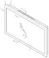
Translated fromKorean도 1은 본 발명에 따른 평면 디스플레이 기기의 사시도.1 is a perspective view of a flat panel display device according to the present invention;
도 2는 본 발명의 평면 디스플레이 기기에서 백커버 상면의 일부를 제거한 부분 절개 사시도.2 is a partial cutaway perspective view of a portion of the upper surface of the back cover of the flat display device of the present invention.
도 3은 도 1의 Ⅰ-Ⅰ' 선의 단면도.3 is a cross-sectional view taken along the line II ′ of FIG. 1.
도 4는 도 1의 Ⅱ-Ⅱ' 선의 단면도.4 is a cross-sectional view taken along the line II-II ′ of FIG. 1.
도 5는 본 발명에 따른 평면 디스플레이 기기의 배면도.5 is a rear view of the flat panel display device according to the present invention;
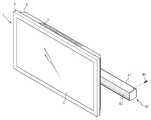
도 6은 필터가 평면 디스플레이 기기의 내부에 제공되지 않고 별도의 부품으로 독립적으로 제공되는 다른 실시예를 설명하기 위한 도면.6 is a view for explaining another embodiment in which the filter is not provided inside the flat panel display device but is provided as a separate component independently.
<도면의 주요 부분에 대한 부호의 설명><Explanation of symbols for main parts of the drawings>
1 : 평면 디스플레이 기기2 : 평면 디스플레이 모듈1: flat display device 2: flat display module
3 : 프론트 커버4 : 백 커버3: front cover 4: back cover
5 : 백커버측 개구부7 : 횡류팬5 back cover side opening 7 cross flow fan
20 : 차폐막30 : 필터20: shielding film 30: filter
본 발명은 평면 디스플레이 기기에 관한 것으로서, 상세하게는 평면 디스플레이 기기의 내부로 먼지등의 이물이 유입되는 것을 방지하고, 특히, 냉각을 위하여 평면 디스플레이 기기의 내부로 유입되는 공기에 의한 오염이 방지되는 평면 디스플레이 기기의 냉각장치에 관한 것이다.The present invention relates to a flat panel display device, and in particular, to prevent foreign substances such as dust from entering into the flat display device, and in particular, to prevent contamination by air introduced into the flat display device for cooling. A cooling device for a flat panel display device.
평면 디스플레이 기기는 일반적인 음극선관과는 달리 메트릭스 형태로 배열되는 구동회로에 의해서, 각 화소의 발광상태가 서로 달리 구현되어 전체적으로 화상을 형성하는 장치이다. 이러한 평면 디스플레이 기기는 상기 음극선관과는 달리 부피가 작기 때문에, 협소한 실내공간에서 차지하는 공간이 작아서 소비자의 선호도가 높고 근래들어 그 사용이 현저하게 증가하고 있다. 상기 평면 디스플레이 기기에 적용되는 평면 디스플레이 모듈은 그 구동방식에 따라서, 액정표시장치(Liquid Crystal Display : LCD), 전계 방출 표시장치(Field Emission Display : FED), 플라즈마 디스플레이 패널(Plasma Display Panel : 이하 "PDP 모듈"이라 함) 및 일렉트로 루미네센스(Electro-Luminescence :EL) 표시장치 등이 있다. 이들 디스플레이 모듈은 부피가 작아서 사용자의 편리함을 추구할 수는 있지만, 폭이 좁은 평면형태의 공간에 집적되어서 제작되기 때문에, 모듈의 구동 중에 발생되는 열이 방출되도록 하는 것은 주요한 해결 과제이다.Unlike general cathode ray tubes, a flat panel display device is a device in which an emission state of each pixel is different from each other by a driving circuit arranged in a matrix form to form an image as a whole. Unlike the cathode ray tube, such a flat panel display device has a small volume, so that the space occupied in a narrow indoor space is small, and thus the use of the flat display device has been increased. The flat panel display module applied to the flat panel display device may be a liquid crystal display (LCD), a field emission display (FED), or a plasma display panel (hereinafter, referred to as "depending on its driving method"). PDP module ”and an Electro-Luminescence (EL) display. Although these display modules are small in volume and can be used for convenience of the user, they are integrated in a narrow flat space, so that heat generated during driving of the module is a major challenge.
특히, PDP 장치는 방전가스의 방전현상 및 전장부품 등에 의해 고온의 열이 발생되고, 이와 같은 열이 방출되지 아니하면 기기가 오작동되거나 고장을 일으키는 주된 요인으로 작용하는 것이 현실이다. 물론, 다른 방식으로 구동되는 평면 디 스플레이 모듈도 방열성능이 기기의 성능을 제한하는 것은 물론이다.In particular, in the PDP device, high temperature heat is generated due to the discharge phenomenon of the discharge gas, electrical components, and the like, and if such heat is not released, the PDP device acts as a major factor causing malfunction or failure of the device. Of course, for flat display modules driven in other ways, the heat dissipation limits the device's performance.
이러한 고열로 인하여 평면 디스플레이 기기의 방열문제를 해결하기 위하여, 종래에는 평면 디스플레이 기기의 커버에 다수의 통기공을 형성하고 형성된 통기구를 통하여 외기가 유입되고 유출되도록 하여 기기 내부의 고열이 방열되도록 하는 방식을 취하였다. 상기 통기구는 커버의 거의 전체영역에 제공되어 전방위적으로 공기가 유입되고 토출되도록 하여 전체적인 평면 디스플레이 기기에 대한 냉각작용이 수행되도록 하였다. 나아가서, 어떠한 경우에는 고온공기가 유출되는 유출구 측에 팬을 더 제공하여 공기의 유속을 증진시키는 방식을 취하였다.In order to solve the heat dissipation problem of the flat panel display device due to such a high temperature, conventionally, a plurality of vent holes are formed in the cover of the flat panel display device, and the outside air is introduced and discharged through the formed vents to heat the high heat inside the device. Was taken. The vent is provided in almost the entire area of the cover to allow air to flow in and out in all directions so that the cooling operation of the entire flat panel display device is performed. Furthermore, in some cases, a fan was further provided on the outlet side through which the hot air was discharged to increase the air flow rate.
그러나, 이와 같은 종래의 방법에 의하면 유입구 및 유출구를 통하여 유입되는 공기를 통하여 미세먼지등의 이물이 함께 유입되고, 유입된 이물이 평면 디스플레이 기기의 내부 부품에 쌓이는 경우에는 기기의 오작동이 유발되는 단점이 있다. 나아가서, 그리고 열이 과도하게 축적되는 경우에는 화재의 위험까지 있는 실정이다. 이와 같은 이물의 유입에 따른 문제는 지하철등과 같이 먼지오염농도가 높은 환경에서는 치명적인 문제로 대두되고 있다.However, according to the conventional method, foreign matters such as fine dust are introduced together through the air flowing through the inlet and the outlet, and when the introduced foreign matter accumulates on the internal parts of the flat panel display device, malfunction of the device is caused. There is this. Furthermore, and if the heat is excessively accumulated there is a risk of fire. This problem caused by the inflow of foreign objects has emerged as a fatal problem in the environment of high dust pollution concentration, such as subway.
또한, 백커버에 외부 공기가 흡입되거나 토출되도록 하기 위하여 다수의 통기구가 형성됨으로써 백커버의 강도를 떨어뜨리는 문제점이 있고, 이러한 강도상의 문제로 인하여 백커버의 재질을 보다 두껍게 형성해야 되기 때문에, 재료비를 상승시키는 문제점이 있다.In addition, since a plurality of vents are formed in order to allow the outside air to be sucked or discharged to the back cover, there is a problem of lowering the strength of the back cover, and due to such a strength problem, the material of the back cover needs to be made thicker, so that the material cost There is a problem to raise.
본 발명은 상기되는 문제점을 개선하기 위하여 제안되는 것으로서, 이물의 오염에 의한 문제가 제거되어, 평면 디스플레이 기기의 안정적인 동작성능과, 화재로 인한 위험을 제거할 수 있는 평면 디스플레이 기기 및 평면 디스플레이 기기의 냉각장치를 제공하는 것을 목적으로 한다.The present invention is proposed to improve the above problems, the problem caused by contamination of foreign matter is eliminated, the stable operation performance of the flat display device and the flat display device and the flat display device that can eliminate the risk of fire It is an object to provide a cooling device.
또한, 평면 디스플레이 기기의 커버에 광범위하게 통기구를 형성할 필요가 없게 되어, 평면 디스플레이 기기의 강도가 향상되고 재료비가 절감되는 평면 디스플레이 기기 및 평면 디스플레이 기기의 냉각장치를 제안하는 것을 목적으로 한다.In addition, an object of the present invention is to propose a flat display device and a cooling device for a flat display device, in which the ventilation of the cover of the flat display device does not need to be formed extensively, thereby improving the strength of the flat display device and reducing the material cost.
또한, 이물질이 많은 극한 조건에서도 평면 디스플레이 기기 내부로의 이물유입이 효과적으로 방지될 수 있도록 함으로써, 평면 디스플레이 기기가 장시간동안 안정적을 동작될 수 있도록 하는 평면 디스플레이 기기의 냉각장치를 제안하는 것을 목적으로 한다.In addition, it is an object of the present invention to propose a cooling device for a flat panel display device to enable the flat panel display device to be stably operated for a long time by effectively preventing foreign matter into the flat display device even under extreme conditions with a lot of foreign matter. .
상기되는 목적을 달성하기 위한 본 발명에 따른 평면 디스플레이 기기는 평면 디스플레이 모듈; 상기 평면 디스플레이 모듈의 외부를 보호하는 커버; 상기 커버의 일측에 형성되어 외기가 흡입되는 흡입구; 상기 커버의 하측 테두리부에 형성되어 상기 커버 내부의 공기가 토출되는 토출구; 상기 토출구와 정렬되어 고온공기를 강제송풍하는 팬; 및 상기 흡입구와 정렬되어 상기 흡입구를 통하여 유입되는 이물을 필터링하는 필터가 포함된다.A flat display device according to the present invention for achieving the above object is a flat display module; A cover protecting the outside of the flat panel display module; A suction port formed at one side of the cover to suck outside air; A discharge hole formed in a lower edge portion of the cover to discharge air inside the cover; A fan aligned with the discharge port and forcibly blowing hot air; And a filter aligned with the suction port to filter foreign substances introduced through the suction port.
다른 측면에 따른 본 발명의 평면 디스플레이 기기의 냉각장치는 평면 디스플레이 모듈; 상기 평면 디스플레이 모듈의 외부를 보호하는 커버; 상기 커버의 일측에 형성되어 외기가 흡입되는 흡입구; 상기 커버의 타측에 형성되어 상기 커버 내부의 고온공기가 토출되는 백커버측 개구부; 상기 백커버측 개구부와 정렬되는 팬; 및 상기 팬의 동작여부에 따라서 선택적으로 상기 백커버측 개구부를 차폐시키는 차폐막이 포함된다.According to another aspect of the present invention, there is provided a cooling apparatus for a flat panel display device; A cover protecting the outside of the flat panel display module; A suction port formed at one side of the cover to suck outside air; A back cover side opening formed at the other side of the cover to discharge hot air from the inside of the cover; A fan aligned with the back cover side opening; And a shielding film for selectively shielding the back cover side opening in accordance with whether the fan is operated.
또 다른 측면에 따른 본 발명의 평면 디스플레이 기기의 냉각장치는 평면 디스플레이 모듈; 상기 평면 디스플레이 모듈의 외부를 보호하는 커버; 상기 커버의 일측에 형성되어 외기가 흡입되는 흡입구; 상기 커버의 타측에 형성되어 상기 커버 내부의 고온 공기가 토출되는 토출구; 상기 토출구측으로 상기 커버 내부의 고온공기를 강제 송풍하는 팬; 및 상기 흡입구와 정렬되어 상기 흡입구를 통하여 유입되는 이물을 필터링하는 필터가 포함되고, 상기 토출구는 상기 팬의 동작시에는 개방되고, 상기 팬의 정지시에는 닫히는 것을 특징으로 한다.Another aspect of the present invention provides a cooling device for a flat panel display device including a flat display module; A cover protecting the outside of the flat panel display module; A suction port formed at one side of the cover to suck outside air; A discharge port formed at the other side of the cover to discharge hot air inside the cover; A fan for forcibly blowing hot air inside the cover to the discharge port; And a filter arranged to be aligned with the suction port to filter foreign substances introduced through the suction port, wherein the discharge port is opened when the fan is operated and closed when the fan is stopped.
제안되는 본 발명에 의해서 평면 디스플레이 기기에 대한 냉각효율이 개선되고, 기기의 내부로 이물의 유입이 방지되고, 동작의 신뢰성 및 안정성이 향상되고,재료비가 절감되는 장점을 얻을 수 있다.According to the present invention, the cooling efficiency of the flat display device is improved, foreign matters are prevented from entering the inside of the device, reliability and stability of the operation are improved, and material costs can be obtained.
이하에서는 도면을 참조하여 본 발명의 바람직한 실시예를 상세하게 설명한다. 다만, 본 발명의 사상은 제시되는 실시예에 제한되지 아니하며, 본 발명의 사상을 이해하는 당업자는 동일한 사상의 범위 내에 포함되는 다른 실시예를 용이하게 제안할 수 있을 것이나, 이 또한 본 발명 사상의 범위 내에 포함된다고 할 것이다.Hereinafter, exemplary embodiments of the present invention will be described in detail with reference to the accompanying drawings. However, the spirit of the present invention is not limited to the embodiments presented, and those skilled in the art who understand the spirit of the present invention can easily suggest other embodiments falling within the scope of the same idea, It is said to be included in the range.
도 1은 본 발명에 따른 평면 디스플레이 기기의 사시도이다.1 is a perspective view of a flat panel display device according to the present invention.
도 1을 참조하면, 본 발명의 평면 디스플레이 기기(1)는 평면 디스플레이 모 듈(2)과, 상기 평면 디스플레이 모듈(2)의 전방을 지지하고 보호하는 프론트 커버(3)와, 평면 디스플레이 모듈(2)의 후방을 지지하고 보호하는 백 커버(4)가 포함된다. 그리고, 상기 배 커버(4)의 상측 테두리에는 평면 디스플레이 기기(1) 내부의 뜨거운 공기가 배출되는 백커버측 개구부(5)가 형성된다. 상기 백커버측 개구부(5)는 다수개의 통공이 집합되는 구조로 제공됨으로써, 백커버(4)의 강도저하가 발생되지 않도록 하는 것이 바람직하다. 다시 말하면, 상기 백커버측 개구부(5)는 전체적으로 평면 디스플레이 기기(1) 내부의 고온공기가 토출되는 부분을 칭하는 것으로서, 그 내부 면적은 다수개의 슬릿이 집합되는 형태로 제공되어 있다.Referring to FIG. 1, the flat
상기 평면 디스플레이 모듈(2)은, 액정표시장치, 전계 방출 표시장치, 플라즈마 디스플레이 패널, 및 일렉트로 루미네센스 표시장치등의 다양한 형태의 메트릭스 형태로 화소가 동작되는 모듈이 적용될 수가 있으나, 바람직하기로는 고열이 발생되는 PDP 모듈이 예시될 수 있다.The flat
상기 프론트 커버(3)와 백커버(4)는 전체적으로 내부 공간에 평면 디스플레이 모듈(2)을 수용한 상태에서 외부와 내부를 구획하고 내부에 장착되는 부품을 보호하는 물품으로서, 본 실시예에서는 프론트 커버(3)와 백커버(4)가 별도의 물품으로 제공되어 양자가 결합되는 양상으로 설명이 되고 있으나, 어떠한 다른 형태로 제공되는 것도 가능하다. 예를 들면, 프론트 커버(3)와 백커버(4)가 단일의 물품으로 제공되는 것도 가능한 일이다. 다만, 프론트 커버(3)가 평면 디스플레이 기기의 전방을 보호하고, 백커버(4)가 평면 디스플레이 기기의 후방을 보호하는 용도로 사용되는 것은 당연하다. 그리고, 상기 백커버(4)의 내면과 평면 디스플레이 모듈(2) 의 후면에 제공되는 다수의 발열부품과의 사이에는 소정의 간격이 제공되고, 상기 간격을 통해서는 공기가 유동하여 상기 발열부품을 냉각시킨 뒤에, 상기 백커버측 개구부(5)를 통하여 배출되는 것도 당연하다.The
상기되는 평면 디스플레이 기기의 사시도를 참조하여 본 발명 냉각장치의 동작을 설명한다.The operation of the cooling apparatus of the present invention will be described with reference to the perspective view of the flat display apparatus described above.
상기 평면 디스플레이 기기(1)가 동작되면, 평면 디스플레이 모듈(2)에는 많은 열이 발생되는데, 특히, 평면 디스플레이 모듈(2)의 후면부의 발열부품에서 발생되는 열은 외부에서 유입된 공기에 의해서 냉각되고, 이후에 뜨거워진 공기는 상방으로 이동한 뒤에 상기 백커버측 개구부(5)를 통하여 외부로 배출되는 과정을 거친다. 이와 같이 뜨거워진 공기가 상방으로 이동되는 자연대류에 과정에 의해서 평면 디스플레이 기기의 내부의 공기가 배출될 수 있기 때문에, 냉각효과가 더욱 증진되는 장점을 얻을 수 있다. 이와 같이 자연대류에 의한 냉각효과가 극대화되도록 하기 위하여, 상기 평면 디스플레이 기기(1)의 내부로 유입되는 공기는 평면 디스플레이 기기(1)의 하단부를 통하여 내부로 유입되도록 하여, 평면 디스플레이 모듈(2)의 후면부를 전체적으로 경유하도록 하여 냉각효율이 더욱 개선되도록 하는 것이 바람직하다.When the flat
설명되는 바와 같은 공기 유동에 의해서 백커버(4)의 배면에 별도의 통기공이 추가적으로 제공될 필요가 없어지는 장점이 있고, 공기의 유입구와 유출구가 커버의 일정위치로만 제한되기 때문에 이물을 거르는 필터부재의 설치가 용이하게 되는 장점을 얻을 수 있다. 또한, 백커버의 배면에 통기공이 별도로 더 형성될 필요 가 없어서 백커버의 배면이 전체적으로 벽면이 닿을 수 있게 되고, 평면 디스플레이 기기의 설치가 더욱 편리해지고 공간을 작게 차지하는 장점을 얻을 수 있다.By the air flow as described there is an advantage that there is no need to additionally provide a separate vent on the back of the
또한, 상기 백커버측 개구부(5)는 백커버(4) 테두리의 경사진 부위에 제공되어 고온공기가 유동되는 방향(상측방향)으로 그대로 토출되도록 함으로써, 고온공기의 유동이 더욱 원활하게 이루어지는 장점이 있다.In addition, the back
물론, 평면 디스플레이 모듈(2)의 전면부는 외부로 노출되어 있기 때문에, 평면 디스플레이 모듈(2)의 전면부에서 발생되는 열이 외부 공기와 자연대류에 의해서 신속하게 방출될 수 있다.Of course, since the front surface of the flat
도 2는 본 발명의 평면 디스플레이 기기에서 백커버 상면의 일부를 제거한 부분 절개 사시도이다.2 is a partially cutaway perspective view of a portion of an upper surface of a back cover of the flat display device of the present invention.
도 2를 참조하면, 상기 백커버(4) 상면에서 상기 백커버측 개구부(5)의 내측에는 횡류팬(7)이 디스플레이 기기가 형성되는 길이방향으로 길게 설치된다. 이와 같이 횡류팬(7)이 설치됨으로써, 백커버(4) 상면은 뜨거운 내부 공기가 외부로 방출되는 면적을 제공하게 된다. 이와 같이 좌우로 길이가 긴 백커버(4) 상면을 통하여 고온공기가 토출될 수 있기 때문에, 공기토출이 보다 용이해져서 공기의 유동저항 및 유동소음이 감소되는 장점을 얻을 수 있다.Referring to FIG. 2, a cross flow fan 7 is installed in the longitudinal direction in which the display device is formed, on the inner side of the back cover
상기 횡류팬(7)의 구성을 보다 상세하게 설명한다. 상기 횡류팬(7)은 백커버(4)의 좌우 길이 방향으로 길게 제공되는 횡류팬 임펠러(10)와 상기 횡류팬 임펠러(10)의 일정 간격으로 횡류팬 임펠러(10)를 구획하고 횡류팬 임펠러(10)의 강도를 보강하는 원형의 플레이트(11)가 포함된다. 또한, 상기 횡류팬(7)의 일단 부위에는 구동축과 상기 구동축에 연결되는 모터(14)가 더 형성되어, 모터(14)의 회전력이 횡류팬(7)으로 전달되도록 한다.The configuration of the cross flow fan 7 will be described in more detail. The crossflow fan 7 partitions the
또한, 상기 횡류팬 임펠러(10)의 회전시에 공기의 유동을 가이드하기 위하여 상기 횡류팬 임펠러(10)는 전체적으로 하우징의 내부에 수용되는데, 상기 하우징은 횡류팬 임펠러(10)의 전방으로 이격된 일측에 형성되는 스크롤(12)과, 이격된 타측에 형성되어 공기의 유동을 안정화시키는 스테빌라이저(13)가 포함된다. 상기 스크롤(12)은 횡류팬 임펠러(10)의 전방에 놓이고, 상기 스테빌라이저(13)는 횡류팬 임펠러(10)의 후방에 놓여서, 상기 횡류팬 임펠러(10)는 도면을 기준으로 시계방향으로 회전하게 된다.In addition, the
한편, 상기 백커버측 개구부(5)의 직근 내측에는 상기 백커버측 개구부(5)를 선택적으로 차폐시키는 차폐막(20)이 놓인다. 상기 차폐막(20)은 상기 횡류팬(7)이 동작될 때에는 상기 백커버측 개구부(5)를 열린 상태로 하여 횡류팬(7)으로부터 송풍된 공기가 토출되도록 하고, 상기 횡류팬(7)이 동작되지 아니할 때에는 상기 백커버측 개구부(5)를 닫힌 상태로 하여 외부로 부터의 공기 및 이물 유입이 차단되도록 한다.On the other hand, a shielding
상기 차폐막(20)과 관련되는 구성을 보다 상세하게 살펴보면, 상기 차폐막(20)은 판상의 좌우방향으로 움직이는 부재로서 적어도 상기 백커버측 개구부(5)보다는 크게 제공된다. 그리고, 상기 차폐막(20)은 백커버(4)의 내면에 형성되는 차폐막 가이드(24)에 의해서 그 위치이동이 가이드된다. 또한, 상기 차폐막(20)이 좌우로 움직이도록 하기 위한 가동구조로서는, 상기 차폐막(20)의 하면에 형성되는 랙(23)과 상기 랙과 치합되는 피니언(22)과 상기 피니언(22)에 연결되는 구동모터(21)가 제공된다. 여기서, 상기 피니언(22)과 상기 모터(21)는 백커버(4) 또는 프론트 커버(3)의 소정위치에 고정되는 것이 바람직하다.Looking at the configuration associated with the shielding
상기 차페막(20)과 관련되는 구성은 설명된 바로 제한되지 아니하고, 여하의 다른 구성으로 구성될 수도 있으나, 상기 차폐막(20)에 의해서 백커버측 개구구(5)가 선택적으로 닫히거나 열릴 수만 있으면 그 또한 본 발명 사상의 범위에 포함된다고 할 것이다.The configuration related to the shielding
이하에서는 외부공기가 유입되는 유입측과 내부의 고온공기가 토출되는 토출측의 구조를 단면도를 참조하여 보다 상세하게 설명한다.Hereinafter, the structure of the inflow side through which the external air is introduced and the discharge side through which the high temperature air is discharged will be described in more detail with reference to the cross-sectional view.
도 3은 도 1의 Ⅰ-Ⅰ' 선의 단면도이다.3 is a cross-sectional view taken along line II ′ of FIG. 1.
도 3을 참조하면, 상기 횡류팬(7)은 이미 설명된 바와 같이 시계 방향으로 회전하는 동작에 의해서, 상기 백커버(4) 내부 공간의 공기가 상방으로 이동하여 스크롤(12)를 따라서 이동된 뒤에, 상기 백커버측 개구부(5)를 통하여 외부로 배출된다.Referring to FIG. 3, the air in the space inside the
설명된 바와 같이 상기 횡류팬(7) 및 백커버측 개구부(5)는 상기 백커버(4) 상면의 길이방향으로 길게 제공되어 있기 때문에, 다량의 고온공기가 토출될 수 있다. 이와 같이 고온공기의 배출면적이 크게 제공됨으로써 공기의 배출에 있어서 저항이 줄어들 수 있고, 이로 인한 공기의 유동 소음이 줄어드는 장점을 얻을 수 있다. 그리고, 고온 공기가 백커버(4)의 상면을 통하여 배출되기 때문에 백커버(4)의 배면과 벽면과의 간격부에는 공기의 원활한 배출을 위한 별도의 간격을 제공할 필 요가 없다. 그러므로, 본 발명의 평면 디스플레이 기기는 벽면에 완전히 말착되어 장착될 수 있고, 그만큼 실내공간을 좁게 차지하는 장점을 얻을 수 있다.As described, since the crossflow fan 7 and the back
또한, 상방향으로 이동된 공기가 이동된 방향 그대로 외부로 토출되기 때문에, 평면 디스플레이 기기 내부의 공기유동은 더욱 원활하게 수행될 수 있는 장점이 있다.In addition, since the air moved upward is discharged to the outside as it is moved, the air flow inside the flat panel display device can be performed more smoothly.
도 4는 도 1의 Ⅱ-Ⅱ'의 단면도이다.4 is a cross-sectional view taken along the line II-II ′ of FIG. 1.
도 4를 참조하면, 백커버(4)의 하단부에는 외부 공기가 흡입되는 측면 흡입구(16)가 형성되고, 상기 측면 흡입구(16)의 내면에는 필터(30)가 부설된다. 상기 필터(30)는 상기 측면 흡입구(16)가 형성되는 부분을 전체적으로 커버하도록 함으로써, 외부에서 흡입되는 공기의 이물이 필터링되도록 한다.Referring to FIG. 4, the lower end portion of the
도 3과 도 4에 제시되는 바와 같이, 평면 디스플레이 기기(1) 내부로 유입되는 공기는 상기 필터(30)에 의해서 이물이 걸러진 상태로 유입되고, 평면 디스플레이 기기(1)가 동작되지 아니할 때에는 백커버측 개구부(5)를 통하여 외부의 이물이 유입되지 않기 때문에, 평면 디스플레이 기기(1) 내부는 이물이 없는 보다 청결한 상태로 놓일 수 있다.As shown in FIG. 3 and FIG. 4, the air flowing into the
그러므로, 본 발명의 평면 디스플레이 기기는 내부공간에 이물이 없는 상태로 유지될 수 있기 때문에, 기기의 동작 신뢰성이 향상되고 발열로 인한 문제점이 개선되고, 화재의 위험이 없는 장점을 얻을 수 있다.Therefore, the flat panel display device of the present invention can be maintained in a state free of foreign matter in the internal space, the operation reliability of the device is improved, the problem caused by heat generation is improved, there is no risk of fire can be obtained.
나아가서, 본 발명에 의해서 지하철 또는 공중장소등과 같이 먼지가 많은 환경에 사용되더라도 디스플레이 기기가 보다 장시간동안 안정적으로 사용될 수 있는 장점이 있다.Furthermore, the present invention has an advantage that the display device can be used stably for a long time even when used in a dusty environment such as a subway or a public place.
도 5는 본 발명에 따른 평면 디스플레이 기기의 배면도이다.5 is a rear view of the flat panel display device according to the present invention.
도 5를 참조하여 본 발명에 따른 평면 디스플레이 기기의 냉각장치의 작용을 설명하면, 상기 백커버(4)에는 백커버측 개구부(5)에 더하여 공기가 백커버(4)의 내부공간으로 유입되도록 하기 위한 흡입구(16)가 더 형성된다.Referring to Figure 5 describes the operation of the cooling device of the flat display device according to the present invention, in addition to the back
상기 흡입구(16)의 작용을 설명하면, 먼저 상기 흡입구(16)는 백커버(4) 하단 테두리부의 경사진 부위에 형성되어 외부의 저온공기가 평면 디스플레이 기기의 내부 공간으로 흡입되도록 한다. 물론, 상기 측면 흡입구(16)를 통하여 흡입되는 공기는 상기 백커버측 개구부(5)를 통하여 배출되는 공기를 보상하기 위하여 흡입되는 공기로서, 자연대류에 의해서 발생되는 음압과 상기 횡류팬(7)에 의해서 토출되는 공기에 의한 평면 디스플레이 기기 내부의 음압을 보상하기 위하여 흡입되는 공기이다. 물론, 상기 흡입구(16)를 통하여 흡입되는 공기 중의 이물은 상기 필터(30)에 의해서 걸러진 상태이기 때문에, 유입되는 공기는 청결한 상태의 공기이다.Referring to the operation of the
이후에, 상기 흡입구(16)를 통하여 흡입되는 공기는, 평면 디스플레이 모듈(2)의 배면에 제공되는 다수 부품의 고열이 전체적으로 냉각되도록 한 뒤에 상기 횡류팬(7)으로 흡입되고 백커버측 개구부(5)를 통하여 배출되는 과정을 거치게 된다.Thereafter, the air sucked through the
또한, 도면에 제시되는 바와 같이 상기 흡입구(16)는 백커버(4) 하단 테두리부의 좌우방향으로 길게 실질적인 하단 테두리부에 전체적으로 형성되도록 함으로써, 흡입되는 공기에 의해서 평면 디스플레이 모듈(2)의 부품이 좌우방향에 걸쳐서 전체적으로 냉각되도록 하는 것이 바람직하다. 도면에서 화살표는 공기의 유동방향을 설명하고 있다.In addition, as shown in the drawing, the
상기 백커버(4) 내부의 고온 공기가 토출되는 작용을 중심으로 설명하면, 상기 횡류팬(7)은 상기 백커버(4)의 상면에 좌우방향으로 길게 백커버(4)의 상면에 길게 형성되어 있다. 그러므로, 상기 백커버(4) 하면을 통하여 흡입된 저온공기는 수직방향으로 그대로 상승하면서 열을 식힌뒤에 상면을 통하여 배출된다.Referring to the operation of discharging the hot air inside the
한편, 상기 평면 디스플레이 모듈(2)의 각 부품 중에서도 특히 고열이 발생되는 부품(예를 들면 전원부)과, 저온조건이 필수적으로 요구되는 부품(예를 들면 TCP 칩(Tape Carrier Package Chip)등과 같이, 한 장의 기판상에 복수의 집적회로 소자를 고밀도로 탑재되는 부품)이 있다. 이와 같은 부품별 동작조건을 만족시키기 위하여, 열적 안정성이 요구되는 부품은 상기 흡입구(16)의 인접위치에 형성되어 외부에서 유입되는 차가운 공기에 의해서 신속하게 냉각되도록 하는 것이 바람직하다. 또한, 다량의 열이 발생되는 부품의 경우에는 발생된 열이 다른 회로부에 영향을 주지 않으면서 신속하게 외부로 배출되도록 하기 위하여, 상기 횡류팬(7)의 인접위치에 형성되는 것이 바람직하다.On the other hand, among the components of the flat
설명된 바와 같이 본 발명에 따른 냉각장치에 의해서 백커버(4)의 어느 일면에 길게 팬이 놓일 수 있기 때문에, 백커버 내부의 고온공기의 방열성능이 한층 더 개선되고, 냉각 장치의 동작 상의 신뢰성이 좋아지는 장점을 얻을 수 있다.As described above, since the fan can be placed on either side of the
한편, 상기 백커버측 개구부(5)의 측편에는 선택적으로 개구부(5)를 차폐시키는 차폐막(20)이 놓이고, 상기 흡입구(16)의 내측에는 필터(30)가 놓여서 그 동 작이 제어된다. 그러므로, 본 발명의 평면 디스프레이 기기의 냉각장치가 동작되는 중에, 기기의 내부로 이물이 유입될 가능성이 줄어드는 이점을 얻을 수 있고, 이로써 기기의 안정적인 동작을 이끌어내는 장점을 얻을 수 있다.On the other hand, a shielding
도 6은 본 발명의 다른 실시예를 설명하기 위한 도면으로서, 상기 필터가 평면 디스플레이 기기의 내부에 제공되지 않고 별도의 부품으로 독립적으로 제공되는 실시예이다.6 is a view for explaining another embodiment of the present invention, in which the filter is not provided inside the flat panel display device but is provided as a separate component independently.
도 6을 참조하면, 평면 디스플레이 기기(1)의 하부에는 별도의 물품으로서 백커버(4)의 배면에 결합되는 필터 어셈블리(40)가 제공된다. 그리고, 상기 필터 어셈블리(40)는 절곡된 단면 형상의 필터 지지부(41)와, 상기 필터 지지부(41)에 안착되는 필터(42)가 포함된다. 그리고, 상기 필터 어셈블리(40)는 나사에 의해서 백커버(4)에 결합된다. 그리고, 도시되지는 않았으나, 상기 필터(42)와 정렬되는 필터 지지부(41)는 전체적으로 개구되거나 복수개의 개공이 가공되도록 하여, 외부공기가 필터(42)를 향하여 유입되도록 하는 것은 당연하다.Referring to FIG. 6, the lower portion of the flat
이러한 필터의 장착구조에 따르면, 상기 필터(42)는 상기 흡입구(16)의 외면을 막아서 흡입구(16)로 유입되는 공기에서 이물을 필터하게 되고, 흡입되는 공기의 청결도를 증진시키게 되는 것은 당연히 짐작될 것이다.According to the mounting structure of the filter, the
본 실시예에 따르면, 필터(42)가 필요한 상태와 필터가 필요치 아니한 상태별로 선택적으로 필터 어셈블리(40)가 장착될 수 있기 때문에, 필터(42)가 필요하게 되지 아니할 때에는 필터(42)의 장착시에 발생될 수 있는 공기의 유동저항과 그로 인한 소비전력이 줄어들게 되는 장점을 얻을 수 있다.According to the present embodiment, since the
한편, 본 발명의 사상에 포함되는 다른 실시예로서, 외부의 저온공기가 유입되는 흡입구는 평면 디스플레이 기기의 상측면부에 형성되고, 내부의 고온공기가 유출되는 토출구인 백커버측 개구부는 평면 디스플레이 기기의 하측면부에 형성되도록 할 수 있다. 이 경우에, 물론 팬은 상기 백커버측 개구부의 직근 내부에 정렬되어 내부 공기가 원활히 유출되도록 할 수 있는 것은 당연하다.On the other hand, as another embodiment included in the spirit of the present invention, the inlet opening for the external low-temperature air is formed in the upper surface portion of the flat display device, the back cover side opening which is the discharge port through which the high-temperature air flows out the flat display device It can be formed on the lower side of the. In this case, it is of course possible that the fan can be aligned inside the rectilinear inside of the back cover side opening to allow the internal air to flow out smoothly.
또한, 이러한 형태의 경우에 상기 백커버측 개구부와 정렬되는 차폐막 및 그 차폐막을 구동과 관련되는 구조는 삭제되도록 할 수도 있다. 이는 상기 차폐막은 외부로부터 유입되는 이물을 차단시키는 것으로서, 고온공기가 토출되는 상기 백커버측 개구부가 상측에 형성될 때, 이를 통하여 이물이 자유낙하되는 것을 방지하기 위한 것이 주 목적인데, 상기 백커버측 개구부가 평면 디스플레이 기기의 하측에 형성되는 경우에는 자유낙하되는 이물이 원천적으로 유입될 염려가 없고, 자유낙하되는 이물이 유입될 수 있는 상기 흡입구는 원천적으로 필터에 의해서 차폐되어 있기 때문에 원래 이물이 유입되지 않기 때문이다.In this case, the shielding film aligned with the back cover side opening and the structure related to driving the shielding film may be deleted. The shielding film is to block foreign substances introduced from the outside, and when the back cover side opening through which hot air is discharged is formed at the upper side, the main purpose is to prevent the foreign substances from falling freely through the back cover. When the side opening is formed below the flat panel display device, there is no fear that freely falling foreign substances may be introduced inherently, and since the suction port where freely falling foreign substances may be introduced is originally shielded by a filter, Because it does not flow.
제안되는 바와 같은 본 발명에 의해서, 평면 디스플레이 기기 내부의 오염에 의한 문제가 제거되어, 평면 디스플레이 기기가 장시간 안정적으로 동작되고, 화재로 인한 위험을 제거할 수 있는 장점이 있다.According to the present invention as proposed, the problem caused by the contamination inside the flat display device is eliminated, the flat display device can be stably operated for a long time, and there is an advantage of eliminating the risk of fire.
또한, 평면 디스플레이 기기의 커버에 광범위하게 통기구를 형성할 필요가 없어지게 되어, 평면 디스플레이 기기의 강도가 향상되고 재료비가 절감되는 장점을 얻을 수 있다.In addition, it is not necessary to form a wide vent on the cover of the flat panel display device, the strength of the flat panel display device can be improved and the material cost can be reduced.
또한, 평면 디스플레이 기기의 단면부에 길이방향으로 흡입구 및 토출구가 제공되기 때문에, 고온공기의 토출구를 제공하기 때문에 구조가 간단해지고, 기기의 두께가 얇아지고 벽면의 설치공간이 축소되는 장점을 얻을 수 있다.In addition, since the suction port and the discharge port are provided in the longitudinal direction in the cross-section of the flat panel display device, since the discharge port of the hot air is provided, the structure can be simplified, the thickness of the device can be reduced, and the installation space on the wall can be obtained. have.
또한, 평면 디스플레이 기기의 내부에서 공기의 유동방향이 개선되어 평면 디스플레이 기기의 설치에 대한 자유도가 개선될 수 있는 장점이 있다.In addition, there is an advantage that the degree of freedom of installation of the flat panel display device can be improved by improving the flow direction of air inside the flat panel display device.
또한, 평면 디스플레이 기기가 오염도가 높은 지하철 및 공공장소등의 장소에 설치되더라도 외부의 오염물질의 영향이 없기 때문에, 이들 고 위험 장소에 대해서도 기기가 신뢰성있게 동작되는 장점을 얻을 수 있다.In addition, even if the flat display device is installed in places with high pollution, such as subways and public places, since there is no influence of external pollutants, the device can be reliably operated even at these high-risk places.
Claims (10)
Translated fromKoreanPriority Applications (4)
| Application Number | Priority Date | Filing Date | Title |
|---|---|---|---|
| KR1020050105179AKR100772247B1 (en) | 2005-11-04 | 2005-11-04 | Chillers for Flat Panel Display Devices and Flat Panel Display Devices |
| US11/505,825US7466546B2 (en) | 2005-11-04 | 2006-08-18 | Flat display device and cooling apparatus for the same |
| CNA2006101218589ACN1960617A (en) | 2005-11-04 | 2006-08-25 | Flat display device and cooling apparatus for the same |
| EP06254520AEP1784070B1 (en) | 2005-11-04 | 2006-08-30 | Flat display device and cooling apparatus for the same |
Applications Claiming Priority (1)
| Application Number | Priority Date | Filing Date | Title |
|---|---|---|---|
| KR1020050105179AKR100772247B1 (en) | 2005-11-04 | 2005-11-04 | Chillers for Flat Panel Display Devices and Flat Panel Display Devices |
Publications (2)
| Publication Number | Publication Date |
|---|---|
| KR20070048300A KR20070048300A (en) | 2007-05-09 |
| KR100772247B1true KR100772247B1 (en) | 2007-11-01 |
Family
ID=37807764
Family Applications (1)
| Application Number | Title | Priority Date | Filing Date |
|---|---|---|---|
| KR1020050105179AExpired - Fee RelatedKR100772247B1 (en) | 2005-11-04 | 2005-11-04 | Chillers for Flat Panel Display Devices and Flat Panel Display Devices |
Country Status (4)
| Country | Link |
|---|---|
| US (1) | US7466546B2 (en) |
| EP (1) | EP1784070B1 (en) |
| KR (1) | KR100772247B1 (en) |
| CN (1) | CN1960617A (en) |
Families Citing this family (71)
| Publication number | Priority date | Publication date | Assignee | Title |
|---|---|---|---|---|
| JP2006152921A (en)* | 2004-11-29 | 2006-06-15 | Sony Corp | Cooling blower fan and video display unit |
| KR100649598B1 (en)* | 2004-12-29 | 2006-11-27 | 엘지전자 주식회사 | Heat dissipation structure of plasma display panel television |
| KR100747820B1 (en)* | 2005-11-04 | 2007-08-08 | 엘지전자 주식회사 | Cooling Units for Flat Panel Display Devices |
| US7463487B2 (en)* | 2005-11-04 | 2008-12-09 | Lg Electronics Inc. | Cooling apparatus for flat display device |
| KR100747849B1 (en)* | 2005-11-04 | 2007-08-08 | 엘지전자 주식회사 | Chillers for Flat Panel Display Devices and Flat Panel Display Devices |
| KR100772247B1 (en)* | 2005-11-04 | 2007-11-01 | 엘지전자 주식회사 | Chillers for Flat Panel Display Devices and Flat Panel Display Devices |
| JP4210860B2 (en)* | 2005-12-26 | 2009-01-21 | 船井電機株式会社 | Panel television and LCD television |
| JP4273357B2 (en)* | 2007-03-06 | 2009-06-03 | 船井電機株式会社 | Cooling fan mounting structure for thin display device and plasma television |
| US20090126907A1 (en)* | 2007-11-16 | 2009-05-21 | Manufacturing Resources International, Inc. | Isolated Gas Heating System for an Electronic Display |
| US8854595B2 (en) | 2008-03-03 | 2014-10-07 | Manufacturing Resources International, Inc. | Constricted convection cooling system for an electronic display |
| US8767165B2 (en)* | 2007-11-16 | 2014-07-01 | Manufacturing Resources International, Inc. | Isolated gas cooling system for an electronic display |
| WO2009065125A2 (en)* | 2007-11-16 | 2009-05-22 | Manufacturing Resources International, Inc. | System and method for thermally controlling an electronic display |
| US12185512B2 (en) | 2007-11-16 | 2024-12-31 | Manufacturing Resources International, Inc. | Electronic display assembly with thermal management |
| TW200932085A (en)* | 2008-01-03 | 2009-07-16 | Coretronic Corp | Display apparatus |
| US8773633B2 (en) | 2008-03-03 | 2014-07-08 | Manufacturing Resources International, Inc. | Expanded heat sink for electronic displays |
| US9173325B2 (en) | 2008-03-26 | 2015-10-27 | Manufacturing Resources International, Inc. | Heat exchanger for back to back electronic displays |
| US8274622B2 (en)* | 2008-03-03 | 2012-09-25 | Manufacturing Resources International, Inc. | System for using constricted convection with closed loop plenum as the convection plate |
| US8654302B2 (en) | 2008-03-03 | 2014-02-18 | Manufacturing Resources International, Inc. | Heat exchanger for an electronic display |
| US8497972B2 (en) | 2009-11-13 | 2013-07-30 | Manufacturing Resources International, Inc. | Thermal plate with optional cooling loop in electronic display |
| US8351014B2 (en) | 2008-03-03 | 2013-01-08 | Manufacturing Resources International, Inc. | Heat exchanger for back to back electronic displays |
| US8693185B2 (en) | 2008-03-26 | 2014-04-08 | Manufacturing Resources International, Inc. | System and method for maintaining a consistent temperature gradient across an electronic display |
| WO2010013307A1 (en)* | 2008-07-28 | 2010-02-04 | Necディスプレイソリューションズ株式会社 | Display device |
| CN102113331A (en)* | 2008-07-29 | 2011-06-29 | 汤姆森特许公司 | Display characterization with filtration |
| US8749749B2 (en) | 2008-12-18 | 2014-06-10 | Manufacturing Resources International, Inc. | System for cooling an electronic image assembly with manifolds and ambient gas |
| US10827656B2 (en) | 2008-12-18 | 2020-11-03 | Manufacturing Resources International, Inc. | System for cooling an electronic image assembly with circulating gas and ambient gas |
| TW201029554A (en)* | 2009-01-21 | 2010-08-01 | Wistron Corp | A dust-proofing method for an electronic device and the electronic device |
| CN101799707B (en)* | 2009-02-06 | 2012-02-08 | 纬创资通股份有限公司 | Dustproof method for electronic device and electronic device |
| CN101995914B (en) | 2009-08-18 | 2012-11-21 | 鸿富锦精密工业(深圳)有限公司 | Notebook computer |
| KR101737391B1 (en)* | 2011-02-01 | 2017-05-30 | 삼성전자주식회사 | Outdoor display apparatus |
| EP2909829B1 (en) | 2012-10-16 | 2020-02-12 | Manufacturing Resources International, INC. | Back pan cooling assembly for electronic display |
| WO2014149773A1 (en) | 2013-03-15 | 2014-09-25 | Manufacturing Resources International, Inc. | Heat exchange assembly for an electronic display |
| US10524384B2 (en) | 2013-03-15 | 2019-12-31 | Manufacturing Resources International, Inc. | Cooling assembly for an electronic display |
| AU2014287438B2 (en) | 2013-07-08 | 2017-09-28 | Manufacturing Resources International, Inc. | Figure eight closed loop cooling system for electronic display |
| ES2876252T3 (en) | 2014-03-11 | 2021-11-12 | Mri Inc | Procedure for mounting a display on a wall |
| CN103917067B (en)* | 2014-03-28 | 2017-03-01 | 京东方科技集团股份有限公司 | Perforate control device and the electronic equipment possessing it |
| JP6305564B2 (en) | 2014-04-30 | 2018-04-04 | マニュファクチャリング・リソーシズ・インターナショナル・インコーポレーテッド | Back-to-back electronic display assembly |
| MA41459A (en) | 2015-02-03 | 2017-12-12 | Als Therapy Development Inst | ANTI-CD40L ANTIBODIES AND METHODS FOR TREATING CD40L ILLNESSES OR DISORDERS |
| US9723765B2 (en) | 2015-02-17 | 2017-08-01 | Manufacturing Resources International, Inc. | Perimeter ventilation system for electronic display |
| CN104833006B (en)* | 2015-04-21 | 2017-10-17 | 陕西理工学院 | A kind of display automatic open-close cover |
| CN105163563B (en)* | 2015-08-27 | 2018-04-17 | 苏州佳世达电通有限公司 | Display device |
| US9622392B1 (en)* | 2015-09-17 | 2017-04-11 | Civiq Smartscapes, Llc | Techniques and apparatus for controlling the temperature of a personal communication structure (PCS) |
| US9451060B1 (en) | 2015-10-15 | 2016-09-20 | Civiq Smartscapes, Llc | Techniques and apparatus for controlling access to components of a personal communication structure (PCS) |
| US9823690B2 (en) | 2015-09-11 | 2017-11-21 | Civiq Smartscapes, Llc | Techniques and apparatus for securing a structure to a support |
| US9703320B2 (en) | 2015-09-17 | 2017-07-11 | Civiq Smartscapes, Llc | Techniques and apparatus for mounting a housing on a personal communication structure (PCS) |
| US10270918B2 (en) | 2015-10-15 | 2019-04-23 | Civiq Smartscapes, Llc | Method and apparatus for power and temperature control of compartments within a personal communication structure (PCS) |
| US20170130948A1 (en)* | 2015-11-05 | 2017-05-11 | Litemax Electronics Inc. | High -brightness panel heat-dissipating apparatus |
| US9516485B1 (en) | 2015-11-13 | 2016-12-06 | Civiq Smartscapes, Llc | Systems and methods for making emergency phone calls |
| WO2017087496A1 (en) | 2015-11-16 | 2017-05-26 | Civiq Smartscapes, Llc | Systems and techniques for vandalism detection in a personal communication structure (pcs) |
| US10820445B2 (en) | 2016-03-04 | 2020-10-27 | Manufacturing Resources International, Inc. | Cooling system for double sided display assembly |
| CN106684971A (en)* | 2016-12-12 | 2017-05-17 | 天长市优信电器设备有限公司 | Charger shell conducive to promoting air circulation |
| KR102262912B1 (en) | 2017-04-27 | 2021-06-10 | 매뉴팩처링 리소시스 인터내셔널 인코포레이티드 | A system and method for preventing warping of a display device |
| US10485113B2 (en) | 2017-04-27 | 2019-11-19 | Manufacturing Resources International, Inc. | Field serviceable and replaceable display |
| US10559965B2 (en) | 2017-09-21 | 2020-02-11 | Manufacturing Resources International, Inc. | Display assembly having multiple charging ports |
| US10602626B2 (en) | 2018-07-30 | 2020-03-24 | Manufacturing Resources International, Inc. | Housing assembly for an integrated display unit |
| US11096317B2 (en) | 2019-02-26 | 2021-08-17 | Manufacturing Resources International, Inc. | Display assembly with loopback cooling |
| US10795413B1 (en) | 2019-04-03 | 2020-10-06 | Manufacturing Resources International, Inc. | Electronic display assembly with a channel for ambient air in an access panel |
| TWI743633B (en)* | 2019-07-16 | 2021-10-21 | 友達光電股份有限公司 | Display |
| TWI709023B (en)* | 2019-09-20 | 2020-11-01 | 廣達電腦股份有限公司 | Portable electronic device |
| US11477923B2 (en) | 2020-10-02 | 2022-10-18 | Manufacturing Resources International, Inc. | Field customizable airflow system for a communications box |
| US11778757B2 (en) | 2020-10-23 | 2023-10-03 | Manufacturing Resources International, Inc. | Display assemblies incorporating electric vehicle charging equipment |
| US11470749B2 (en) | 2020-10-23 | 2022-10-11 | Manufacturing Resources International, Inc. | Forced air cooling for display assemblies using centrifugal fans |
| US11966263B2 (en) | 2021-07-28 | 2024-04-23 | Manufacturing Resources International, Inc. | Display assemblies for providing compressive forces at electronic display layers |
| US12408312B2 (en) | 2021-07-28 | 2025-09-02 | Manufacturing Resources International, Inc. | Display assemblies with vents |
| US11762231B2 (en) | 2021-08-23 | 2023-09-19 | Manufacturing Resources International, Inc. | Display assemblies inducing turbulent flow |
| US11919393B2 (en) | 2021-08-23 | 2024-03-05 | Manufacturing Resources International, Inc. | Display assemblies inducing relatively turbulent flow and integrating electric vehicle charging equipment |
| US11744054B2 (en) | 2021-08-23 | 2023-08-29 | Manufacturing Resources International, Inc. | Fan unit for providing improved airflow within display assemblies |
| US11968813B2 (en) | 2021-11-23 | 2024-04-23 | Manufacturing Resources International, Inc. | Display assembly with divided interior space |
| US12010813B2 (en) | 2022-07-22 | 2024-06-11 | Manufacturing Resources International, Inc. | Self-contained electronic display assembly, mounting structure and methods for the same |
| US12072561B2 (en) | 2022-07-22 | 2024-08-27 | Manufacturing Resources International, Inc. | Self-contained electronic display assembly, mounting structure and methods for the same |
| US12035486B1 (en) | 2022-07-25 | 2024-07-09 | Manufacturing Resources International, Inc. | Electronic display assembly with fabric panel communications box |
| CN118484068A (en)* | 2023-02-10 | 2024-08-13 | 苏州佳世达电通有限公司 | Electronic device |
Citations (4)
| Publication number | Priority date | Publication date | Assignee | Title |
|---|---|---|---|---|
| JPH1141547A (en) | 1997-07-22 | 1999-02-12 | Matsushita Electric Ind Co Ltd | Rear projection device |
| KR20000002033A (en)* | 1998-06-16 | 2000-01-15 | 윤종용 | Filtrating device of projection television set |
| JP2000305175A (en) | 1999-04-20 | 2000-11-02 | Fujitsu General Ltd | LCD projector |
| KR20050047624A (en)* | 2003-11-18 | 2005-05-23 | 주식회사 대우일렉트로닉스 | Auto air slit shutting device for the projection television |
Family Cites Families (32)
| Publication number | Priority date | Publication date | Assignee | Title |
|---|---|---|---|---|
| US3177794A (en)* | 1960-04-14 | 1965-04-13 | Laing Nikolaus | Automobile-windshield defroster |
| US5038577A (en)* | 1990-02-12 | 1991-08-13 | Inter-City Products Corporation (Usa) | Air intake arrangement for air conditioner with dual cross flow blowers |
| JPH0448693A (en)* | 1990-06-14 | 1992-02-18 | Mitsubishi Electric Corp | Portable electronic apparatus |
| US5497573A (en)* | 1994-04-14 | 1996-03-12 | Stadjuhar; Robert C. | Thermally-protected display with a ventilation system |
| JP3234740B2 (en)* | 1994-06-09 | 2001-12-04 | キヤノン株式会社 | Image display device |
| KR0182545B1 (en)* | 1995-05-18 | 1999-05-01 | 김광호 | Odor removing device of air conditioner and control method |
| KR100187231B1 (en)* | 1995-12-30 | 1999-05-01 | 김광호 | Air Conditioner and Control Method |
| KR0168255B1 (en)* | 1996-03-21 | 1999-03-20 | 김광호 | Inlet opening and closing device of air conditioner |
| KR0182588B1 (en)* | 1996-09-03 | 1999-05-01 | 김광호 | Opening and closing control device of air conditioner and its method |
| KR0168265B1 (en)* | 1996-09-03 | 1999-01-15 | 김광호 | Wind direction control apparatus and method for an airconditioner |
| DK0837288T3 (en)* | 1996-10-15 | 2002-09-09 | Aermec Spa | Ventilation convector with adjustable deflector elements |
| JP2000124624A (en) | 1998-10-20 | 2000-04-28 | Fujitsu General Ltd | Plasma display device |
| KR100543440B1 (en)* | 1998-12-01 | 2006-03-23 | 삼성전자주식회사 | A ac/dc voltage converter and portable electron system with the same |
| WO2000062591A1 (en)* | 1999-04-13 | 2000-10-19 | Siemens Aktiengesellschaft | Device for cooling an electric module and a technical appliance |
| JP2000307281A (en) | 1999-04-20 | 2000-11-02 | Fujitsu General Ltd | Mounting structure of PDP cooling sirocco fan |
| TW458258U (en)* | 2000-12-01 | 2001-10-01 | Koochingchai Pong | Improved structure for wind-wheel and wind-channel of separated air conditioner |
| TW517833U (en)* | 2002-04-24 | 2003-01-11 | Koochingchai Pong | Improved ventilating structure for wind wheel of split air conditioning and heating machine |
| US20040223299A1 (en)* | 2003-05-07 | 2004-11-11 | Prosenjit Ghosh | Display cooling |
| TWI280338B (en)* | 2003-09-16 | 2007-05-01 | Lg Electronics Inc | Integral type air conditioner and front panel thereof |
| TWI267611B (en)* | 2003-09-16 | 2006-12-01 | Lg Electronics Inc | Integral type air conditioner and air guide structure thereof |
| TWI259890B (en)* | 2003-09-16 | 2006-08-11 | Lg Electronics Inc | Integral type air conditioner |
| US20050105012A1 (en) | 2003-10-28 | 2005-05-19 | Kim Sung K. | Display |
| US20050168942A1 (en)* | 2004-02-04 | 2005-08-04 | Steinbrecher Robin A. | Airflow gates for electronic devices |
| KR20050117665A (en)* | 2004-06-11 | 2005-12-15 | 엘지전자 주식회사 | Indoor unit for air conditioner |
| KR100638047B1 (en)* | 2004-10-15 | 2006-10-23 | 엘지전자 주식회사 | Liquid crystal display with backlight unit |
| JP2006152921A (en)* | 2004-11-29 | 2006-06-15 | Sony Corp | Cooling blower fan and video display unit |
| KR100649598B1 (en)* | 2004-12-29 | 2006-11-27 | 엘지전자 주식회사 | Heat dissipation structure of plasma display panel television |
| KR100731366B1 (en)* | 2005-11-04 | 2007-06-21 | 엘지전자 주식회사 | Cooling devices for flat panel display devices and transverse flow fans therefor |
| KR100747820B1 (en)* | 2005-11-04 | 2007-08-08 | 엘지전자 주식회사 | Cooling Units for Flat Panel Display Devices |
| US7463487B2 (en)* | 2005-11-04 | 2008-12-09 | Lg Electronics Inc. | Cooling apparatus for flat display device |
| KR100747849B1 (en)* | 2005-11-04 | 2007-08-08 | 엘지전자 주식회사 | Chillers for Flat Panel Display Devices and Flat Panel Display Devices |
| KR100772247B1 (en)* | 2005-11-04 | 2007-11-01 | 엘지전자 주식회사 | Chillers for Flat Panel Display Devices and Flat Panel Display Devices |
- 2005
- 2005-11-04KRKR1020050105179Apatent/KR100772247B1/ennot_activeExpired - Fee Related
- 2006
- 2006-08-18USUS11/505,825patent/US7466546B2/enactiveActive
- 2006-08-25CNCNA2006101218589Apatent/CN1960617A/enactivePending
- 2006-08-30EPEP06254520Apatent/EP1784070B1/ennot_activeCeased
Patent Citations (4)
| Publication number | Priority date | Publication date | Assignee | Title |
|---|---|---|---|---|
| JPH1141547A (en) | 1997-07-22 | 1999-02-12 | Matsushita Electric Ind Co Ltd | Rear projection device |
| KR20000002033A (en)* | 1998-06-16 | 2000-01-15 | 윤종용 | Filtrating device of projection television set |
| JP2000305175A (en) | 1999-04-20 | 2000-11-02 | Fujitsu General Ltd | LCD projector |
| KR20050047624A (en)* | 2003-11-18 | 2005-05-23 | 주식회사 대우일렉트로닉스 | Auto air slit shutting device for the projection television |
Also Published As
| Publication number | Publication date |
|---|---|
| EP1784070A3 (en) | 2009-10-21 |
| US20070103866A1 (en) | 2007-05-10 |
| KR20070048300A (en) | 2007-05-09 |
| US7466546B2 (en) | 2008-12-16 |
| EP1784070A2 (en) | 2007-05-09 |
| EP1784070B1 (en) | 2012-02-22 |
| CN1960617A (en) | 2007-05-09 |
Similar Documents
| Publication | Publication Date | Title |
|---|---|---|
| KR100772247B1 (en) | Chillers for Flat Panel Display Devices and Flat Panel Display Devices | |
| KR100747820B1 (en) | Cooling Units for Flat Panel Display Devices | |
| KR100747848B1 (en) | Cooling Units for Flat Panel Display Devices | |
| US7463487B2 (en) | Cooling apparatus for flat display device | |
| US7369407B2 (en) | Flat display device and cooling apparatus for the same | |
| US20120255704A1 (en) | Image display apparatus | |
| KR101387932B1 (en) | Display unit and vending maching having the same | |
| CN101207981A (en) | cabinet | |
| JP2006330196A (en) | Plasma television and video display device | |
| KR100731366B1 (en) | Cooling devices for flat panel display devices and transverse flow fans therefor | |
| KR100805400B1 (en) | Cooling Units for Flat Panel Display Devices | |
| CN103912926B (en) | outdoor unit | |
| KR20100100660A (en) | Fan filter unit, semiconductor manufacturing apparatus, flat panel display manufacturing apparatus and method of manufacturing cleaned air | |
| KR100731382B1 (en) | Cooling Units for Flat Panel Display Devices | |
| KR100693516B1 (en) | Mounting device for flat panel display device and flat panel display device | |
| KR100784767B1 (en) | Air conditioner | |
| JP4831207B2 (en) | Air conditioner | |
| JP4760957B2 (en) | Air conditioner | |
| JP2002057480A (en) | Cooling unit and display device provided with cooling unit | |
| KR100592263B1 (en) | Plasma display device | |
| KR100751113B1 (en) | Flat panel display device and its installation | |
| CN117177519A (en) | A kind of network security equipment and network security system | |
| JP2010027642A (en) | Electronic equipment | |
| JP2011128433A (en) | Image display device |
Legal Events
| Date | Code | Title | Description |
|---|---|---|---|
| A201 | Request for examination | ||
| PA0109 | Patent application | St.27 status event code:A-0-1-A10-A12-nap-PA0109 | |
| PA0201 | Request for examination | St.27 status event code:A-1-2-D10-D11-exm-PA0201 | |
| D13-X000 | Search requested | St.27 status event code:A-1-2-D10-D13-srh-X000 | |
| D14-X000 | Search report completed | St.27 status event code:A-1-2-D10-D14-srh-X000 | |
| E902 | Notification of reason for refusal | ||
| PE0902 | Notice of grounds for rejection | St.27 status event code:A-1-2-D10-D21-exm-PE0902 | |
| P11-X000 | Amendment of application requested | St.27 status event code:A-2-2-P10-P11-nap-X000 | |
| P13-X000 | Application amended | St.27 status event code:A-2-2-P10-P13-nap-X000 | |
| PG1501 | Laying open of application | St.27 status event code:A-1-1-Q10-Q12-nap-PG1501 | |
| E701 | Decision to grant or registration of patent right | ||
| PE0701 | Decision of registration | St.27 status event code:A-1-2-D10-D22-exm-PE0701 | |
| GRNT | Written decision to grant | ||
| PR0701 | Registration of establishment | St.27 status event code:A-2-4-F10-F11-exm-PR0701 | |
| PR1002 | Payment of registration fee | St.27 status event code:A-2-2-U10-U11-oth-PR1002 Fee payment year number:1 | |
| PG1601 | Publication of registration | St.27 status event code:A-4-4-Q10-Q13-nap-PG1601 | |
| G170 | Re-publication after modification of scope of protection [patent] | ||
| PG1701 | Publication of correction | St.27 status event code:A-5-5-P10-P19-oth-PG1701 Patent document republication publication date:20080415 Republication note text:Request for Correction Notice (Document Request) Gazette number:1007722470000 Gazette reference publication date:20071101 | |
| PN2301 | Change of applicant | St.27 status event code:A-5-5-R10-R13-asn-PN2301 St.27 status event code:A-5-5-R10-R11-asn-PN2301 | |
| R18-X000 | Changes to party contact information recorded | St.27 status event code:A-5-5-R10-R18-oth-X000 | |
| R18-X000 | Changes to party contact information recorded | St.27 status event code:A-5-5-R10-R18-oth-X000 | |
| PR1001 | Payment of annual fee | St.27 status event code:A-4-4-U10-U11-oth-PR1001 Fee payment year number:4 | |
| PR1001 | Payment of annual fee | St.27 status event code:A-4-4-U10-U11-oth-PR1001 Fee payment year number:5 | |
| FPAY | Annual fee payment | Payment date:20120926 Year of fee payment:6 | |
| PR1001 | Payment of annual fee | St.27 status event code:A-4-4-U10-U11-oth-PR1001 Fee payment year number:6 | |
| FPAY | Annual fee payment | Payment date:20130924 Year of fee payment:7 | |
| PR1001 | Payment of annual fee | St.27 status event code:A-4-4-U10-U11-oth-PR1001 Fee payment year number:7 | |
| FPAY | Annual fee payment | Payment date:20140924 Year of fee payment:8 | |
| PR1001 | Payment of annual fee | St.27 status event code:A-4-4-U10-U11-oth-PR1001 Fee payment year number:8 | |
| PN2301 | Change of applicant | St.27 status event code:A-5-5-R10-R13-asn-PN2301 St.27 status event code:A-5-5-R10-R11-asn-PN2301 | |
| FPAY | Annual fee payment | Payment date:20150924 Year of fee payment:9 | |
| PR1001 | Payment of annual fee | St.27 status event code:A-4-4-U10-U11-oth-PR1001 Fee payment year number:9 | |
| FPAY | Annual fee payment | Payment date:20160923 Year of fee payment:10 | |
| PR1001 | Payment of annual fee | St.27 status event code:A-4-4-U10-U11-oth-PR1001 Fee payment year number:10 | |
| FPAY | Annual fee payment | Payment date:20170922 Year of fee payment:11 | |
| PR1001 | Payment of annual fee | St.27 status event code:A-4-4-U10-U11-oth-PR1001 Fee payment year number:11 | |
| FPAY | Annual fee payment | Payment date:20180921 Year of fee payment:12 | |
| PR1001 | Payment of annual fee | St.27 status event code:A-4-4-U10-U11-oth-PR1001 Fee payment year number:12 | |
| FPAY | Annual fee payment | Payment date:20190924 Year of fee payment:13 | |
| PR1001 | Payment of annual fee | St.27 status event code:A-4-4-U10-U11-oth-PR1001 Fee payment year number:13 | |
| PN2301 | Change of applicant | St.27 status event code:A-5-5-R10-R13-asn-PN2301 St.27 status event code:A-5-5-R10-R11-asn-PN2301 | |
| PR1001 | Payment of annual fee | St.27 status event code:A-4-4-U10-U11-oth-PR1001 Fee payment year number:14 | |
| PR1001 | Payment of annual fee | St.27 status event code:A-4-4-U10-U11-oth-PR1001 Fee payment year number:15 | |
| PR1001 | Payment of annual fee | St.27 status event code:A-4-4-U10-U11-oth-PR1001 Fee payment year number:16 | |
| PC1903 | Unpaid annual fee | St.27 status event code:A-4-4-U10-U13-oth-PC1903 Not in force date:20231026 Payment event data comment text:Termination Category : DEFAULT_OF_REGISTRATION_FEE | |
| PC1903 | Unpaid annual fee | St.27 status event code:N-4-6-H10-H13-oth-PC1903 Ip right cessation event data comment text:Termination Category : DEFAULT_OF_REGISTRATION_FEE Not in force date:20231026 |