KR100772057B1 - Safety syringe and its disposal method - Google Patents
Safety syringe and its disposal methodDownload PDFInfo
- Publication number
- KR100772057B1 KR100772057B1KR1020060046462AKR20060046462AKR100772057B1KR 100772057 B1KR100772057 B1KR 100772057B1KR 1020060046462 AKR1020060046462 AKR 1020060046462AKR 20060046462 AKR20060046462 AKR 20060046462AKR 100772057 B1KR100772057 B1KR 100772057B1
- Authority
- KR
- South Korea
- Prior art keywords
- injection
- protective cap
- holder
- cylinder
- injection needle
- Prior art date
- Legal status (The legal status is an assumption and is not a legal conclusion. Google has not performed a legal analysis and makes no representation as to the accuracy of the status listed.)
- Expired - Fee Related
Links
Images


Classifications
- A—HUMAN NECESSITIES
- A61—MEDICAL OR VETERINARY SCIENCE; HYGIENE
- A61M—DEVICES FOR INTRODUCING MEDIA INTO, OR ONTO, THE BODY; DEVICES FOR TRANSDUCING BODY MEDIA OR FOR TAKING MEDIA FROM THE BODY; DEVICES FOR PRODUCING OR ENDING SLEEP OR STUPOR
- A61M5/00—Devices for bringing media into the body in a subcutaneous, intra-vascular or intramuscular way; Accessories therefor, e.g. filling or cleaning devices, arm-rests
- A61M5/178—Syringes
- A61M5/31—Details
- A61M5/32—Needles; Details of needles pertaining to their connection with syringe or hub; Accessories for bringing the needle into, or holding the needle on, the body; Devices for protection of needles
- A61M5/3205—Apparatus for removing or disposing of used needles or syringes, e.g. containers; Means for protection against accidental injuries from used needles
- A61M5/321—Means for protection against accidental injuries by used needles
- A61M5/3243—Means for protection against accidental injuries by used needles being axially-extensible, e.g. protective sleeves coaxially slidable on the syringe barrel
- A61M5/3245—Constructional features thereof, e.g. to improve manipulation or functioning
Landscapes
- Health & Medical Sciences (AREA)
- Engineering & Computer Science (AREA)
- Heart & Thoracic Surgery (AREA)
- Vascular Medicine (AREA)
- Anesthesiology (AREA)
- Biomedical Technology (AREA)
- Environmental & Geological Engineering (AREA)
- Hematology (AREA)
- Life Sciences & Earth Sciences (AREA)
- Animal Behavior & Ethology (AREA)
- General Health & Medical Sciences (AREA)
- Public Health (AREA)
- Veterinary Medicine (AREA)
- Infusion, Injection, And Reservoir Apparatuses (AREA)
Abstract
Description
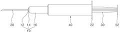
Translated fromKorean도 1은 본 발명의 제1 실시 예에 따른 안전 주사기를 나타내는 분해 사시도이다.1 is an exploded perspective view showing a safety syringe according to a first embodiment of the present invention.
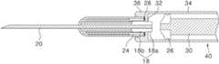
도 2는 도 1에 도시된 안전 주사기를 나타내는 분해 단면도이다.2 is an exploded cross-sectional view showing the safety syringe shown in FIG.
도 3은 도 1에 도시된 안전 주사기의 주사 완료전을 나타내는 단면도이다.3 is a cross-sectional view showing before the injection of the safety syringe shown in FIG.
도 4는 도 1에 도시된 안전 주사기의 주사 완료후를 나타내는 단면도이다.4 is a cross-sectional view showing the completion of the injection of the safety syringe shown in FIG.
도 5a 내지 도 5d는 도 1에 도시된 안전 주사기의 사용방법을 설명하기 위한 도5A to 5D are views for explaining a method of using the safety syringe shown in FIG.
도 6은 본 발명의 제2 실시 예에 따른 안전 주사기를 나타내는 분해 사시도이다.6 is an exploded perspective view showing a safety syringe according to a second embodiment of the present invention.
도 7은 도 6에 도시된 안전 주사기의 주사 완료후를 나타내는 단면도이다.7 is a cross-sectional view showing the completion of the injection of the safety syringe shown in FIG.
< 도면의 주요부분에 대한 설명><Description of Main Parts of Drawing>
10,12,14,16 : 보호캡18 : 홀더10, 12, 14, 16: protective cap 18: holder
20 : 주사바늘22 : 손잡이부20: needle 22: handle portion
24,62 : 허브26 : 패킹부24, 62
28 : 오링30 : 플런저28: O-ring 30: plunger
32 : 연결홀34,36 : 수용부32: connecting
38 : 결합홈40 : 실린더38: coupling groove 40: cylinder
42 : 스토퍼44 : 가이드돌기42: stopper 44: guide protrusion
46 : 가이드 라인48 : 랩핑부46 guideline 48: lapping part
52 : 가압판58 : 걸림턱52: pressure plate 58: locking jaw
60 : 밀봉캡60: sealing cap
본 발명은 안전 주사기 및 그 폐기방법에 관한 것으로, 특히 주사 완료 후 주사기 취급자가 주사바늘에 찔려 2차 감염되는 것을 방지할 수 있는 안전 주사기 및 그 폐기방법에 관한 것이다.The present invention relates to a safety syringe and a method for disposing thereof, and more particularly, to a safety syringe and a method for disposing of the syringe after the completion of the injection can be prevented from being stuck by the needle needle.
일반적으로, 주사기는 주사 바늘과, 주사 바늘과 결합되며 원통형으로 형성된 실린더와, 실린더 내부에 슬라이드 가능하게 결합되어 실린더 내부로 약액을 빨아들이거나 실린더 내부의 약액을 외부로 토출시키는 플런저(Plunger)를 구비한다. 이러한 주사기를 사용한 후 주사 바늘에 보호캡을 씌운 후 폐기 처분하게 된다. 이 때, 주사기 취급자인 의사나 간호사가 주사바늘에 찔리는 경우가 종종 발생되 며, 또한 주사기의 폐기 처분 과정에서도 주사바늘에 씌워진 보호캡이 분리되어 폐기 처리자도 주사 바늘에 찔리는 경우가 종종 발생된다. 이 경우, B형 감염 환자 또는 에이즈 환자 등과 같이 전염성 병원균을 가지고 있는 환자에게 사용한 주사 바늘에 주사기 취급자 또는 폐기 처리자가 찔리는 경우 2차 감염되는 문제점이 있다.Generally, a syringe includes a needle, a cylinder coupled to the needle and formed in a cylindrical shape, and a plunger slidably coupled inside the cylinder to suck the chemical into the cylinder or to discharge the chemical into the cylinder to the outside. Equipped. After using such a syringe, a protective cap is put on the injection needle and discarded. At this time, the doctor or nurse, the syringe handler, is often stuck in the needle, and in the process of disposing of the syringe, the protective cap covered by the needle is detached and the waste processor is often stuck in the needle. In this case, there is a problem of secondary infection when a syringe handler or a waste processor is stuck in an injection needle used for a patient with an infectious pathogen, such as a B-type infection patient or AIDS patient.
이러한 문제점을 해결하기 위해, 주사 행위 직후 주사 바늘이 실린더 내부로 슬라이딩되는 안전 주사기가 사용되고 있다. 그러나, 종래 안전 주사기는 실린더 내부로 주사 바늘이 삽입된 채로 폐기 처분된다. 즉, 재활용이 가능한 실린더 등의 일반성 폐기물이 재활용되지 못하고 주사 바늘 등의 감염성 폐기물과 함께 폐기 처분되는 문제점이 있다.In order to solve this problem, a safety syringe has been used in which the injection needle slides into the cylinder immediately after the injection action. However, conventional safety syringes are disposed of with the injection needle inserted into the cylinder. That is, there is a problem that general waste such as a cylinder that can be recycled cannot be recycled and disposed of together with infectious waste such as a needle.
따라서, 본 발명이 이루고자 하는 기술적 과제는 주사 완료 후 주사기 취급자가 주사바늘에 찔려 2차 감염되는 것을 방지할 수 있는 안전 주사기 및 그 폐기방법을 제공하는 것이다.Accordingly, the technical problem to be achieved by the present invention is to provide a safety syringe and its disposal method which can prevent the syringe handler from being stuck in the needle and secondary infection after completion of the injection.
또한, 본 발명이 이루고자 하는 다른 기술적 과제는 주사 완료 후 주사기의 감염성 폐기물과 일반성 폐기물을 구분하여 폐기할 수 있는 안전 주사기 및 그 폐기 방법을 제공하는 것이다.In addition, another technical problem to be achieved by the present invention is to provide a safety syringe and a method of disposing thereof that can be disposed of the infectious and general waste of the syringe after completion of the injection.
상기 기술적 과제를 달성하기 위하여, 본 발명에 따른 안전 주사기는 주사 바늘과; 상기 주사 바늘에 공급된 주사액을 수용하는 실린더와; 상기 실린더 내부에 슬라이드 가능하게 결합된 플런저와; 상기 플런저에 가해지는 압력이 상기 주사시와 주사 완료 후 연속적으로 이어져 상기 주사 완료 후 상기 주사바늘을 감싸도록 순차적으로 전진 운동하는 다수개의 보호캡을 구비하는 것을 특징으로 한다.In order to achieve the above technical problem, the safety syringe according to the present invention and the injection needle; A cylinder for receiving an injection liquid supplied to the injection needle; A plunger slidably coupled inside the cylinder; The pressure applied to the plunger is continuously provided after the injection and the injection is completed, characterized in that it comprises a plurality of protective caps to sequentially move forward to surround the needle after the completion of the injection.
상기 안전 주사기는 상기 주사 바늘을 고정하며 상기 플런저의 압력을 상기 보호캡에 전달하는 홀더를 추가로 구비하며, 상기 홀더는 상기 주사 바늘의 입구부에 형성되는 제1 홀더와; 상기 제1 홀더의 직경보다 큰 직경으로 형성되는 제2 홀더를 포함하는 것을 특징으로 한다.The safety syringe further includes a holder for holding the injection needle and transmitting a pressure of the plunger to the protective cap, the holder having a first holder formed at an inlet of the injection needle; And a second holder formed to a diameter larger than the diameter of the first holder.
상기 다수개의 보호캡은 서로 다른 직경을 가지는 원통형으로 형성된 것을 특징으로 한다.The plurality of protective caps are formed in a cylindrical shape having a different diameter.
상기 다수개의 보호캡은 상기 안전 주사기의 피취급자에게 상기 주사액을 주사시 서로를 감싸도록 형성되며, 주사 후 상기 홀더의 압력에 의해 최내곽에 위치하는 보호캡부터 순차적으로 전진운동하는 것을 특징으로 한다.The plurality of protective caps are formed to surround each other when the injection of the injection to the patient of the safety syringe, characterized in that the forward movement sequentially from the protective cap located in the innermost by the pressure of the holder after injection .
상기 다수개의 보호캡 각각은 내부에 홈 형태의 가이드 라인을 가지는 랩핑부와; 상기 랩핑부의 일측단으로부터 상기 주사 바늘쪽인 내부로 수직하게 신장된 스토퍼와; 상기 랩핑부의 타측단으로부터 외부로 수직하게 신장된 가이드 돌기를 포함하는 것을 특징으로 한다.Each of the plurality of protective caps has a wrapping portion having a guide line of the groove shape therein; A stopper extending vertically from one side end of the wrapping portion toward the injection needle; It characterized in that it comprises a guide projection extending vertically outward from the other end of the wrapping portion.
상기 안전 주사기는 상기 최외곽에 위치하는 보호캡과 제2 홀더 사이에 위치하는 제1 허브를 추가로 구비하는 것을 특징으로 한다.The safety syringe further comprises a first hub positioned between the protective cap positioned at the outermost side and the second holder.
상기 안전 주사기는 상기 주사 후 상기 보호캡 내부로 유입되는 제1 홀더와 상기 최외곽에 위치하는 보호캡 사이에 위치하는 제2 허브를 추가로 구비하는 것을 특징으로 한다.The safety syringe further includes a second hub positioned between the first holder introduced into the protective cap after the injection and the protective cap positioned at the outermost portion.
상기 기술적 과제를 달성하기 위하여, 본 발명에 따른 안전 주사기의 폐기 방법은 주사 바늘, 상기 주사 바늘에 공급된 주사액을 수용하는 실린더, 상기 실린더 내부에 슬라이드 가능하게 결합된 플런저, 상기 실린더와 탈부착이 가능한 다수개의 보호캡을 포함하며 주사가 완료된 안전 주사기를 마련하는 단계와; 주사시 상기 플런저에 가해지는 압력이 주사 완료 후 연속적으로 이어져 상기 주사바늘을 감싸도록 상기 다수개의 보호캡이 순차적으로 전진운동하는 단계를 포함하는 것을 특징으로 한다.In order to achieve the above technical problem, a method for disposing of a safety syringe according to the present invention includes a syringe, a cylinder containing an injection liquid supplied to the injection needle, a plunger slidably coupled inside the cylinder, and detachable from the cylinder. Providing a safety syringe that includes a plurality of protective caps and has been injected; And a plurality of protective caps sequentially moving forward so that the pressure applied to the plunger during the injection continues continuously after the injection is completed to surround the needle.
상기 안전 주사기의 폐기 방법은 상기 주사바늘을 감쌈과 아울러 상기 주사 바늘이 내부에 고정된 상기 보호캡과 상기 실린더를 분리하는 단계를 추가로 포함하는 것을 특징으로 한다.Disposal of the safety syringe is characterized in that it further comprises the step of wrapping the needle and separating the cylinder and the protective cap fixed to the injection needle therein.
이하, 본 발명의 바람직한 실시 예를 도 1 내지 도 7을 참조하여 상세히 설명하기로 한다.Hereinafter, preferred embodiments of the present invention will be described in detail with reference to FIGS. 1 to 7.
도 1 및 도 2는 본 발명에 따른 안전 주사기를 나타내는 분해 사시도 및 분해 단면도이다.1 and 2 are exploded perspective and exploded cross-sectional view showing a safety syringe according to the present invention.
도 1 및 도 2에 도시된 안전주사기는 주사 바늘(20)과, 주사 바늘(20)과 결합되며 원통형태로 형성된 실린더(40)와, 실린더(40) 내부에 슬라이드 가능하게 결합되는 플런저(30)와, 주사 후 주사 바늘(20)을 감싸는 보호캡(10)을 구비한다.The safety syringe shown in FIGS. 1 and 2 is coupled to the
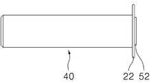
플런저(30)는 실린더(40)의 길이 방향을 따라 실린더(40)의 내부를 전후 방향으로 이동될 수 있도록 실린더(40) 내부에 삽입된다. 이러한 플린저(30)의 이동에 따라서 실린더(40) 내부로 주사액이 흡입되거나 실린더(40) 내부의 주사액이 외부로 배출된다. 이러한 플런저(30)의 일측단에는 고무 재질의 패킹부(26)가 형성된다. 이 패킹부(26)는 플런저(30)의 전후방 이동시 실린더(40)와 기밀 접촉된 상태로 함께 이동하면서 압축력 또는 흡입력을 제공한다. 그리고, 플런저(30)의 타측단에는 플런저(30)를 실린더(40) 내부로 이동시킬 때 이용되는 가압판(52)이 형성된다.The
실린더(40)는 도 2에 도시된 바와 같이 연결홀(32)을 통해 연통되는 제1 및 제2 수용부(34,36)와, 제1 수용부(34)의 일측단에 형성되는 손잡이부(22)를 구비한다.As shown in FIG. 2, the
제1 수용부(34)에는 플런저(30)의 동작에 따라서 내부로 흡입되거나 외부로 배출되는 주사약이 수용된다. 제2 수용부(36)에는 도 3에 도시된 바와 같이 주사 바늘(20)을 고정하는 홀더(18), 홀더(18)와 체결된 허브(24) 등이 삽입된 보호캡(10)이 끼워진다. 특히, 보호캡(10) 중 제3 보호캡(16)의 제3 가이드 돌기(44c)는 제3 보호캡(16)과 실린더(40)가 탈부착가능하도록 제2 수용부(36)의 결합홈(38)에 체결된다. 손잡이부(22)에는 주사기 사용시 주사기 취급자인 의사 또는 간호사의 손가락이 지지된다.Injecting medicine that is sucked into the inside or discharged to the outside according to the operation of the
주사 바늘(20)은 그 주사 바늘(20)의 직경과 동일한 직경을 가지는 중공 형태의 홀더(18)에 고정된다. 홀더(18)는 도 3에 도시된 바와 같이 실린더(40)의 제 1 수용부(34) 내에 삽입되는 제1 홀더(18a)와, 제1 홀더(18a)의 직경보다 큰 직경을 가지도록 형성되는 제2 홀더(18b)를 구비한다.The
제1 홀더(18a)는 주사 전에는 연결홀(32)을 통해 제1 수용부(34) 내에 삽입된다. 이에 따라, 제1 홀더(18a)에 의해 고정된 주사 바늘(20)의 입구에는 제1 수용부(34) 내의 주사액이 공급된다. 그리고, 제1 홀더(18a)는 도 4에 도시된 바와 같이 주사 후에는 패킹부(26)와 기밀 접촉된 플런저(30)의 압력에 의해 제2 수용부(36) 내부로 이동된다.The
제2 홀더(18b)는 연결홀(32)을 마련하는 실린더(40)의 걸림턱(58)에 의해 제1 수용부(34)내로 유입되는 것이 방지된다. 이러한 제2 홀더(18b)는 주사 전에는 허브(24)에 의해 제3 보호캡(16) 내에 고정됨과 아울러 오링(28)에 의해 제2 수용부(36) 내에 고정된다. 그리고, 제2 홀더(18b)를 고정하는 허브(24)는 주사 후에는 오링(28)과 이격된다.The
보호캡(10)은 서로 다른 직경을 가지는 다수개의 서브 보호캡을 구비한다. 여기서는 3개의 보호캡을 예로 들어 설명하기로 한다. 제1 내지 제3 보호캡(12,14,16)은 환자에게 주사액을 주사시 서로를 감싸도록 형성되며, 주사 후 홀더(18)의 압력에 의해 최내곽에 위치하는 제1 보호캡(12)부터 순차적으로 전진 운동한다.The
이를 위해, 제1 내지 제3 보호캡(12,14,16) 각각은 홈 형태의 가이드 라인(46a,46b,46c)을 가지는 랩핑부(48a,48b,48c)와, 랩핑부(48a,48b,48c)의 일측단으로부터 주사 바늘(20)쪽인 내부로 수직하게 신장된 스토퍼(42a,42b,42c)와, 랩핑부(48a,48b,48c)의 타측단으로부터 외부로 수직하게 신장된 가이드 돌기 (44a,44b,44c)를 구비한다.To this end, each of the first to third
랩핑부(48a,48b,48c)는 제1 보호캡(12), 제2 보호캡(14), 제3 보호캡(16) 순서대로 직경이 커지도록 형성된다. 구체적으로 제1 보호캡(12)의 제1 랩핑부(48a)는 주사 바늘(20)보다 큰 직경을 가지며, 제2 보호캡(14)의 제2 랩핑부(48b)는 제1 보호캡(12)의 제1 랩핑부(48a)보다 큰 직경을 가지며, 제3 보호캡(16)의 제3 랩핑부(48c)는 제2 보호캡(14)의 제2 랩핑부(48b)보다 큰 직경을 가진다. 이러한 제1 내지 제3 랩핑부(48a,48b,48c)는 주사 후 주사 바늘(20)을 감싸도록 형성된다.The
제 1 및 제2 가이드 돌기(44a,44b) 각각은 제2 및 제3 랩핑부(48b,48c)각각의 가이드 라인(46b,46c) 내에 삽입되어 그 가이드 라인(46b,46c)을 따라서 전진이동하게 된다. 한편, 제3 가이드 돌기(44c)는 실린더(40)의 제2 수용부(36) 내에 고정된다.Each of the first and
제2 및 제3 스토퍼(42b,42c) 각각은 주사 후 제1 및 제2 가이드 돌기(44a,44b) 각각과 결합되어 제1 및 제2 보호캡(12,14)의 전진운동을 정지시킨다.Each of the second and
이러한 제1 내지 제3 보호캡(12,14,16)은 폴리에틸렌과 같은 플라스틱 재질로 형성된다.The first to third
도 5a 내지 도 5d는 본 발명에 따른 안전 주사기의 사용방법을 설명하기 위한 도면들이다. 이에 대하여 도 1 내지 도 4를 결부하여 상세히 설명하기로 한다.5A to 5D are views for explaining a method of using the safety syringe according to the present invention. This will be described in detail with reference to FIGS. 1 to 4.
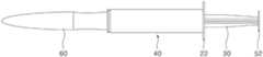
도 5a에 도시된 바와 같이 주사 전에 주사 바늘(20)의 손상을 방지하기 위해 주사 바늘(20)을 감싸도록 형성된 밀봉캡(60)을 가지는 안전 주사기를 마련한다. 이 후, 도 5b에 도시된 바와 같이 밀봉캡(60)을 주사 바늘(20)로부터 분리시켜 주 사 바늘(20)을 외부로 노출시킨다. 그런 다음, 주사기 취급자인 의사나 간호사는 가압판(52)에 압력을 가하여 플런저(30)가 전진운동함으로써 실린더(40) 내의 주사액이 환자에게 주입된다. 주사가 완료되면 주사기 취급자는 패킹부(26)와 기밀 접촉된 플런저(30)가 주사 바늘(20)을 고정하는 홀더(18)와 접촉하도록 가압판(52)에 압력을 가한다. 가압판(52)에 가해진 압력에 의해 허브(24)의 걸림턱(50)에 고정된 제1 보호캡(12)의 가이드 돌기(44a)는 허브(24)의 걸림턱(50)으로부터 이탈되어 제2 가이드 라인(46b)을 따라서 전진이동하게 된다. 이 후, 제1 보호캡(12)의 가이드 돌기(44a)는 제2 보호캡(14)의 스토퍼(42b)와 결합되어 전진 이동을 멈추게 된다. 이와 동시에 제1 보호캡(12)의 전진력이 제2 보호캡(14)에 전달되어 제2 보호캡의(14) 가이드 돌기(44b)는 제3 가이드 라인(46c)을 따라서 전진 이동하게 된다. 이 후, 제2 보호캡(14)의 가이드 돌기(44b)는 제3 보호캡(16)의 스토퍼(42c)와 결합되어 전진 이동을 멈추게 된다. 이와 같이, 전진 이동된 제1 내지 제3 보호캡(12,14,16)은 도 5c에 도시된 바와 같이 주사 바늘(20)을 감싸도록 형성되어 주사기 취급자들이 주사 바늘(20)에 찔려 2차 감염되는 것을 방지할 수 있다. 이와 같이, 제1 내지 제3 보호캡(12,14,16)은 주사완료 후 가압판(52)에 가해지는 압력에 의해 순차적으로 전진운동하게 되어 주사 바늘(20)을 감싸게 된다. 즉, 본 발명에 따른 안전 주사기는 주사시와 주사 후 연속적으로 가압판(52)에 가해지는 한번의 가압공정에 의해 주사 공정과 주사 바늘(20)의 밀봉 공정이 이루어지므로 공정이 단순하다. 반면에 종래 안전 주사기는 주사시 가압판에 가해지는 가압 공정과, 주사 후 가압 공정과 별개인 주사 바늘의 밀봉 공정이 개별적으로 이루어지 므로 공정이 복잡하다.As shown in FIG. 5A, a safety syringe having a sealing
이 후, 도 5d에 도시된 바와 같이 제3 보호캡(16)의 가이드 돌기(44c)를 제2 수용부(36)의 결합홈(38)으로부터 이탈시킨다. 제2 수용부(36)의 결합홈(38)으로부터 이탈된 제3 보호캡(16)과, 제3 보호캡(16)과 결합된 제1 및 제2 보호캡(12,14), 제3 보호캡(16)과 결합된 허브(24), 허브(24)에 고정된 주사 홀더(18), 주사 홀더(18)에 고정된 주사 바늘(20)을 포함하는 감염성 폐기물들은 폐기 처분된다. 그리고, 나머지 실린더(40)와 플런저(30)를 포함하는 일반성 폐기물들은 폐기 처분되거나 재사용이 가능한다. 이에 따라, 본 발명에 따른 안전 주사기는 감염성 폐기물들을 선택적으로 폐기할 수 있으므로 폐기물 처리 비용이 종래보다 감소하게 된다.Thereafter, as illustrated in FIG. 5D, the
도 6 및 도 7은 본 발명의 제2 실시 예에 따른 안전 주사기를 나타내는 도면들이다.6 and 7 are views illustrating a safety syringe according to a second embodiment of the present invention.
도 6 및 도 7에 도시된 안전 주사기는 도 1 내지 도 4에 도시된 안전주사기와 대비하여 제2 허브를 추가로 구비하는 것을 제외하고는 동일한 구성요소를 구비한다. 이에 따라, 동일한 구성요소에 대한 상세한 설명은 생략하기로 한다.The safety syringe shown in FIGS. 6 and 7 has the same components except that it further comprises a second hub as compared to the safety syringes shown in FIGS. Accordingly, detailed description of the same components will be omitted.
제1 허브(24)는 제2 홀더(18b)가 끼워지도록 제2 홀더(18b)의 직경과 동일한 크기의 홀을 가지는 원형의 띠형태로 형성된다.The
제2 허브(62)는 제2 수용부(34) 내의 제1 허브(24)와 오링(28) 사이에 위치하게 된다. 이러한 제2 허브(60)는 주사 후에 실린더(40)의 제2 수용부(36) 내로 유입되는 제1 홀더(18a)를 고정시킨다. 이를 위해, 제2 허브(62)는 제1 홀더(18a) 가 끼워지도록 제1 홀더(18a)의 직경과 동일한 크기의 홀을 가지도록 원형의 띠형태로 형성된다.The
상술한 바와 같이, 본 발명에 따른 안전 주사기 및 그 폐기 방법은 주사 후 다수개의 보호캡이 순차적으로 전진이동하여 주사 바늘을 감싸게 된다. 이에 따라, 본 발명에 따른 안전 주사기 및 그 폐기 방법은 주사기 취급자 및 폐기 처리자가 주사 바늘에 찔려 2차 감염되는 것을 방지할 수 있다.As described above, the safety syringe and its disposal method according to the present invention is a plurality of protective caps are sequentially moved forward after the injection to wrap the injection needle. Accordingly, the safety syringe and its disposal method according to the present invention can prevent the syringe handler and the disposal processor from being stabbed into the injection needle for secondary infection.
또한, 본 발명에 따른 안전 주사기 및 그 폐기 방법은 실린더와 플런저를 포함하는 일반성 폐기물들을 제외한 감염성 폐기물들만을 선택적으로 제거함으로써 종래에 비해 폐기물 양이 줄어든다. 이에 따라, 본 발명에 따른 안전 주사기 및 그 폐기 방법은 종래에 비해 폐기물 처리 비용이 절감된다.In addition, the safety syringe and its disposal method according to the present invention reduces the amount of waste compared to the prior art by selectively removing only infectious wastes except general wastes including cylinders and plungers. Accordingly, the safety syringe and its disposal method according to the present invention can reduce the waste disposal cost compared to the prior art.
이상 설명한 내용을 통해 당업자라면 본 발명의 기술사상을 일탈하지 아니하는 범위에서 다양한 변경 및 수정이 가능함을 알 수 있을 것이다. 따라서, 본 발명의 기술적 범위는 명세서의 상세한 설명에 기재된 내용으로 한정되는 것이 아니라 특허 청구의 범위에 의해 정하여져야만 할 것이다.Those skilled in the art will appreciate that various changes and modifications can be made without departing from the technical spirit of the present invention. Therefore, the technical scope of the present invention should not be limited to the contents described in the detailed description of the specification but should be defined by the claims.
Claims (9)
Translated fromKoreanPriority Applications (1)
| Application Number | Priority Date | Filing Date | Title |
|---|---|---|---|
| KR1020060046462AKR100772057B1 (en) | 2006-05-24 | 2006-05-24 | Safety syringe and its disposal method |
Applications Claiming Priority (1)
| Application Number | Priority Date | Filing Date | Title |
|---|---|---|---|
| KR1020060046462AKR100772057B1 (en) | 2006-05-24 | 2006-05-24 | Safety syringe and its disposal method |
Publications (1)
| Publication Number | Publication Date |
|---|---|
| KR100772057B1true KR100772057B1 (en) | 2007-10-31 |
Family
ID=38816492
Family Applications (1)
| Application Number | Title | Priority Date | Filing Date |
|---|---|---|---|
| KR1020060046462AExpired - Fee RelatedKR100772057B1 (en) | 2006-05-24 | 2006-05-24 | Safety syringe and its disposal method |
Country Status (1)
| Country | Link |
|---|---|
| KR (1) | KR100772057B1 (en) |
Cited By (4)
| Publication number | Priority date | Publication date | Assignee | Title |
|---|---|---|---|---|
| WO2016159719A1 (en)* | 2015-04-02 | 2016-10-06 | 고려대학교 산학협력단 | Syringe needle |
| CN107281594A (en)* | 2016-04-12 | 2017-10-24 | 上海金塔医用器材有限公司 | Injection needle |
| CN110917447A (en)* | 2019-12-31 | 2020-03-27 | 江苏苏云医疗器材有限公司 | Telescopic anti-acupuncture injection needle |
| KR20210046397A (en)* | 2019-10-18 | 2021-04-28 | 주식회사 필텍바이오 | Safety syringe protection cap |
Citations (6)
| Publication number | Priority date | Publication date | Assignee | Title |
|---|---|---|---|---|
| JPH0458256U (en)* | 1990-09-27 | 1992-05-19 | ||
| US5403286A (en)* | 1992-10-28 | 1995-04-04 | Lockwood, Jr.; Hanford N. | Hypodermic needle safety device with sliding outer cover |
| JPH07328119A (en)* | 1994-06-06 | 1995-12-19 | Apere:Kk | Needle protector for injector |
| KR200249064Y1 (en)* | 2001-05-25 | 2001-10-19 | 신현달 | Safety needle |
| KR200254002Y1 (en)* | 2001-08-24 | 2001-11-23 | 방영철 | safety syringe |
| KR20020088246A (en)* | 2001-05-19 | 2002-11-27 | 신현달 | Cylinder,needle and cap unified safety syringe. |
- 2006
- 2006-05-24KRKR1020060046462Apatent/KR100772057B1/ennot_activeExpired - Fee Related
Patent Citations (6)
| Publication number | Priority date | Publication date | Assignee | Title |
|---|---|---|---|---|
| JPH0458256U (en)* | 1990-09-27 | 1992-05-19 | ||
| US5403286A (en)* | 1992-10-28 | 1995-04-04 | Lockwood, Jr.; Hanford N. | Hypodermic needle safety device with sliding outer cover |
| JPH07328119A (en)* | 1994-06-06 | 1995-12-19 | Apere:Kk | Needle protector for injector |
| KR20020088246A (en)* | 2001-05-19 | 2002-11-27 | 신현달 | Cylinder,needle and cap unified safety syringe. |
| KR200249064Y1 (en)* | 2001-05-25 | 2001-10-19 | 신현달 | Safety needle |
| KR200254002Y1 (en)* | 2001-08-24 | 2001-11-23 | 방영철 | safety syringe |
Cited By (5)
| Publication number | Priority date | Publication date | Assignee | Title |
|---|---|---|---|---|
| WO2016159719A1 (en)* | 2015-04-02 | 2016-10-06 | 고려대학교 산학협력단 | Syringe needle |
| CN107281594A (en)* | 2016-04-12 | 2017-10-24 | 上海金塔医用器材有限公司 | Injection needle |
| KR20210046397A (en)* | 2019-10-18 | 2021-04-28 | 주식회사 필텍바이오 | Safety syringe protection cap |
| KR102342500B1 (en)* | 2019-10-18 | 2021-12-23 | 주식회사 필텍바이오 | Safety syringe protection cap |
| CN110917447A (en)* | 2019-12-31 | 2020-03-27 | 江苏苏云医疗器材有限公司 | Telescopic anti-acupuncture injection needle |
Similar Documents
| Publication | Publication Date | Title |
|---|---|---|
| US7393345B2 (en) | Sterilized safety syringe | |
| EP3178504B1 (en) | Package and package assembly | |
| CN102711872B (en) | Pen needle removal device for a drug delivery device | |
| KR100772057B1 (en) | Safety syringe and its disposal method | |
| AU5765401A (en) | Hypodermic syringe with selectively retractable needle | |
| AU2004210146A1 (en) | Retracting needle assembly for a syringe | |
| CN1048983A (en) | Hypodermic syringe | |
| MXPA03005836A (en) | Hypodermic syringe with selectively retractable needle. | |
| KR102354662B1 (en) | Non-reusable disposable safety syringe | |
| KR20160144117A (en) | Safety syringe | |
| KR101234057B1 (en) | Safe syringe | |
| KR200350792Y1 (en) | disposable safety syringe | |
| KR101869465B1 (en) | Syringe needle cap for preventing reuse | |
| KR102173408B1 (en) | Preventing reuse of disposable syringes | |
| KR101087651B1 (en) | Disposable safety syringe | |
| KR100618125B1 (en) | Disposable safety syringe | |
| KR101993597B1 (en) | Syringe | |
| KR102618124B1 (en) | Holder For Liquid Medicine Cartridge | |
| KR200368201Y1 (en) | disposable safety syringe | |
| KR20190016359A (en) | syringe | |
| KR101733295B1 (en) | Injection Needle Remover | |
| KR102743897B1 (en) | Finger grip for syringes having a flange fitting part with a protrusion structure | |
| CN211486011U (en) | Syringe | |
| KR101742803B1 (en) | Safety filter syringe | |
| KR200380851Y1 (en) | Injecting Device |
Legal Events
| Date | Code | Title | Description |
|---|---|---|---|
| A201 | Request for examination | ||
| PA0109 | Patent application | St.27 status event code:A-0-1-A10-A12-nap-PA0109 | |
| PA0201 | Request for examination | St.27 status event code:A-1-2-D10-D11-exm-PA0201 | |
| PN2301 | Change of applicant | St.27 status event code:A-3-3-R10-R13-asn-PN2301 St.27 status event code:A-3-3-R10-R11-asn-PN2301 | |
| R18-X000 | Changes to party contact information recorded | St.27 status event code:A-3-3-R10-R18-oth-X000 | |
| D13-X000 | Search requested | St.27 status event code:A-1-2-D10-D13-srh-X000 | |
| D14-X000 | Search report completed | St.27 status event code:A-1-2-D10-D14-srh-X000 | |
| E902 | Notification of reason for refusal | ||
| PE0902 | Notice of grounds for rejection | St.27 status event code:A-1-2-D10-D21-exm-PE0902 | |
| E13-X000 | Pre-grant limitation requested | St.27 status event code:A-2-3-E10-E13-lim-X000 | |
| P11-X000 | Amendment of application requested | St.27 status event code:A-2-2-P10-P11-nap-X000 | |
| P13-X000 | Application amended | St.27 status event code:A-2-2-P10-P13-nap-X000 | |
| E701 | Decision to grant or registration of patent right | ||
| PE0701 | Decision of registration | St.27 status event code:A-1-2-D10-D22-exm-PE0701 | |
| GRNT | Written decision to grant | ||
| PR0701 | Registration of establishment | St.27 status event code:A-2-4-F10-F11-exm-PR0701 | |
| PR1002 | Payment of registration fee | St.27 status event code:A-2-2-U10-U11-oth-PR1002 Fee payment year number:1 | |
| PG1601 | Publication of registration | St.27 status event code:A-4-4-Q10-Q13-nap-PG1601 | |
| PR1001 | Payment of annual fee | St.27 status event code:A-4-4-U10-U11-oth-PR1001 Fee payment year number:4 | |
| PR1001 | Payment of annual fee | St.27 status event code:A-4-4-U10-U11-oth-PR1001 Fee payment year number:5 | |
| FPAY | Annual fee payment | Payment date:20121009 Year of fee payment:6 | |
| PR1001 | Payment of annual fee | St.27 status event code:A-4-4-U10-U11-oth-PR1001 Fee payment year number:6 | |
| FPAY | Annual fee payment | Payment date:20131022 Year of fee payment:7 | |
| PR1001 | Payment of annual fee | St.27 status event code:A-4-4-U10-U11-oth-PR1001 Fee payment year number:7 | |
| R18-X000 | Changes to party contact information recorded | St.27 status event code:A-5-5-R10-R18-oth-X000 | |
| FPAY | Annual fee payment | Payment date:20141006 Year of fee payment:8 | |
| PR1001 | Payment of annual fee | St.27 status event code:A-4-4-U10-U11-oth-PR1001 Fee payment year number:8 | |
| LAPS | Lapse due to unpaid annual fee | ||
| PC1903 | Unpaid annual fee | St.27 status event code:A-4-4-U10-U13-oth-PC1903 Not in force date:20151026 Payment event data comment text:Termination Category : DEFAULT_OF_REGISTRATION_FEE | |
| PC1903 | Unpaid annual fee | St.27 status event code:N-4-6-H10-H13-oth-PC1903 Ip right cessation event data comment text:Termination Category : DEFAULT_OF_REGISTRATION_FEE Not in force date:20151026 | |
| P22-X000 | Classification modified | St.27 status event code:A-4-4-P10-P22-nap-X000 |