KR100771768B1 - Self-Powered Small Liquid Handling System - Google Patents
Self-Powered Small Liquid Handling SystemDownload PDFInfo
- Publication number
- KR100771768B1 KR100771768B1KR1020067007076AKR20067007076AKR100771768B1KR 100771768 B1KR100771768 B1KR 100771768B1KR 1020067007076 AKR1020067007076 AKR 1020067007076AKR 20067007076 AKR20067007076 AKR 20067007076AKR 100771768 B1KR100771768 B1KR 100771768B1
- Authority
- KR
- South Korea
- Prior art keywords
- liquid
- housing
- generator
- hydro
- flow
- Prior art date
- Legal status (The legal status is an assumption and is not a legal conclusion. Google has not performed a legal analysis and makes no representation as to the accuracy of the status listed.)
- Expired - Fee Related
Links
Images


Classifications
- H—ELECTRICITY
- H02—GENERATION; CONVERSION OR DISTRIBUTION OF ELECTRIC POWER
- H02K—DYNAMO-ELECTRIC MACHINES
- H02K7/00—Arrangements for handling mechanical energy structurally associated with dynamo-electric machines, e.g. structural association with mechanical driving motors or auxiliary dynamo-electric machines
- H02K7/18—Structural association of electric generators with mechanical driving motors, e.g. with turbines
- H02K7/1807—Rotary generators
- H02K7/1823—Rotary generators structurally associated with turbines or similar engines
- C—CHEMISTRY; METALLURGY
- C02—TREATMENT OF WATER, WASTE WATER, SEWAGE, OR SLUDGE
- C02F—TREATMENT OF WATER, WASTE WATER, SEWAGE, OR SLUDGE
- C02F1/00—Treatment of water, waste water, or sewage
- C02F1/008—Control or steering systems not provided for elsewhere in subclass C02F
- C—CHEMISTRY; METALLURGY
- C02—TREATMENT OF WATER, WASTE WATER, SEWAGE, OR SLUDGE
- C02F—TREATMENT OF WATER, WASTE WATER, SEWAGE, OR SLUDGE
- C02F1/00—Treatment of water, waste water, or sewage
- C02F1/30—Treatment of water, waste water, or sewage by irradiation
- C02F1/32—Treatment of water, waste water, or sewage by irradiation with ultraviolet light
- C02F1/325—Irradiation devices or lamp constructions
- C—CHEMISTRY; METALLURGY
- C02—TREATMENT OF WATER, WASTE WATER, SEWAGE, OR SLUDGE
- C02F—TREATMENT OF WATER, WASTE WATER, SEWAGE, OR SLUDGE
- C02F9/00—Multistage treatment of water, waste water or sewage
- C02F9/20—Portable or detachable small-scale multistage treatment devices, e.g. point of use or laboratory water purification systems
- E—FIXED CONSTRUCTIONS
- E03—WATER SUPPLY; SEWERAGE
- E03C—DOMESTIC PLUMBING INSTALLATIONS FOR FRESH WATER OR WASTE WATER; SINKS
- E03C1/00—Domestic plumbing installations for fresh water or waste water; Sinks
- E03C1/02—Plumbing installations for fresh water
- E03C1/08—Jet regulators or jet guides, e.g. anti-splash devices
- F—MECHANICAL ENGINEERING; LIGHTING; HEATING; WEAPONS; BLASTING
- F03—MACHINES OR ENGINES FOR LIQUIDS; WIND, SPRING, OR WEIGHT MOTORS; PRODUCING MECHANICAL POWER OR A REACTIVE PROPULSIVE THRUST, NOT OTHERWISE PROVIDED FOR
- F03B—MACHINES OR ENGINES FOR LIQUIDS
- F03B1/00—Engines of impulse type, i.e. turbines with jets of high-velocity liquid impinging on blades or like rotors, e.g. Pelton wheels; Parts or details peculiar thereto
- F—MECHANICAL ENGINEERING; LIGHTING; HEATING; WEAPONS; BLASTING
- F03—MACHINES OR ENGINES FOR LIQUIDS; WIND, SPRING, OR WEIGHT MOTORS; PRODUCING MECHANICAL POWER OR A REACTIVE PROPULSIVE THRUST, NOT OTHERWISE PROVIDED FOR
- F03B—MACHINES OR ENGINES FOR LIQUIDS
- F03B13/00—Adaptations of machines or engines for special use; Combinations of machines or engines with driving or driven apparatus; Power stations or aggregates
- C—CHEMISTRY; METALLURGY
- C02—TREATMENT OF WATER, WASTE WATER, SEWAGE, OR SLUDGE
- C02F—TREATMENT OF WATER, WASTE WATER, SEWAGE, OR SLUDGE
- C02F1/00—Treatment of water, waste water, or sewage
- C02F1/001—Processes for the treatment of water whereby the filtration technique is of importance
- C—CHEMISTRY; METALLURGY
- C02—TREATMENT OF WATER, WASTE WATER, SEWAGE, OR SLUDGE
- C02F—TREATMENT OF WATER, WASTE WATER, SEWAGE, OR SLUDGE
- C02F1/00—Treatment of water, waste water, or sewage
- C02F1/28—Treatment of water, waste water, or sewage by sorption
- C02F1/283—Treatment of water, waste water, or sewage by sorption using coal, charred products, or inorganic mixtures containing them
- C—CHEMISTRY; METALLURGY
- C02—TREATMENT OF WATER, WASTE WATER, SEWAGE, OR SLUDGE
- C02F—TREATMENT OF WATER, WASTE WATER, SEWAGE, OR SLUDGE
- C02F1/00—Treatment of water, waste water, or sewage
- C02F1/30—Treatment of water, waste water, or sewage by irradiation
- C02F1/32—Treatment of water, waste water, or sewage by irradiation with ultraviolet light
- C—CHEMISTRY; METALLURGY
- C02—TREATMENT OF WATER, WASTE WATER, SEWAGE, OR SLUDGE
- C02F—TREATMENT OF WATER, WASTE WATER, SEWAGE, OR SLUDGE
- C02F2201/00—Apparatus for treatment of water, waste water or sewage
- C02F2201/002—Construction details of the apparatus
- C—CHEMISTRY; METALLURGY
- C02—TREATMENT OF WATER, WASTE WATER, SEWAGE, OR SLUDGE
- C02F—TREATMENT OF WATER, WASTE WATER, SEWAGE, OR SLUDGE
- C02F2201/00—Apparatus for treatment of water, waste water or sewage
- C02F2201/009—Apparatus with independent power supply, e.g. solar cells, windpower or fuel cells
- C—CHEMISTRY; METALLURGY
- C02—TREATMENT OF WATER, WASTE WATER, SEWAGE, OR SLUDGE
- C02F—TREATMENT OF WATER, WASTE WATER, SEWAGE, OR SLUDGE
- C02F2201/00—Apparatus for treatment of water, waste water or sewage
- C02F2201/32—Details relating to UV-irradiation devices
- C—CHEMISTRY; METALLURGY
- C02—TREATMENT OF WATER, WASTE WATER, SEWAGE, OR SLUDGE
- C02F—TREATMENT OF WATER, WASTE WATER, SEWAGE, OR SLUDGE
- C02F2201/00—Apparatus for treatment of water, waste water or sewage
- C02F2201/32—Details relating to UV-irradiation devices
- C02F2201/322—Lamp arrangement
- C02F2201/3222—Units using UV-light emitting diodes [LED]
- C—CHEMISTRY; METALLURGY
- C02—TREATMENT OF WATER, WASTE WATER, SEWAGE, OR SLUDGE
- C02F—TREATMENT OF WATER, WASTE WATER, SEWAGE, OR SLUDGE
- C02F2201/00—Apparatus for treatment of water, waste water or sewage
- C02F2201/32—Details relating to UV-irradiation devices
- C02F2201/326—Lamp control systems
- C—CHEMISTRY; METALLURGY
- C02—TREATMENT OF WATER, WASTE WATER, SEWAGE, OR SLUDGE
- C02F—TREATMENT OF WATER, WASTE WATER, SEWAGE, OR SLUDGE
- C02F2209/00—Controlling or monitoring parameters in water treatment
- C02F2209/005—Processes using a programmable logic controller [PLC]
- C—CHEMISTRY; METALLURGY
- C02—TREATMENT OF WATER, WASTE WATER, SEWAGE, OR SLUDGE
- C02F—TREATMENT OF WATER, WASTE WATER, SEWAGE, OR SLUDGE
- C02F2209/00—Controlling or monitoring parameters in water treatment
- C02F2209/005—Processes using a programmable logic controller [PLC]
- C02F2209/006—Processes using a programmable logic controller [PLC] comprising a software program or a logic diagram
- C—CHEMISTRY; METALLURGY
- C02—TREATMENT OF WATER, WASTE WATER, SEWAGE, OR SLUDGE
- C02F—TREATMENT OF WATER, WASTE WATER, SEWAGE, OR SLUDGE
- C02F2307/00—Location of water treatment or water treatment device
- C02F2307/06—Mounted on or being part of a faucet, shower handle or showerhead
- E—FIXED CONSTRUCTIONS
- E03—WATER SUPPLY; SEWERAGE
- E03C—DOMESTIC PLUMBING INSTALLATIONS FOR FRESH WATER OR WASTE WATER; SINKS
- E03C2201/00—Details, devices or methods not otherwise provided for
- E03C2201/40—Arrangement of water treatment devices in domestic plumbing installations
- F—MECHANICAL ENGINEERING; LIGHTING; HEATING; WEAPONS; BLASTING
- F05—INDEXING SCHEMES RELATING TO ENGINES OR PUMPS IN VARIOUS SUBCLASSES OF CLASSES F01-F04
- F05B—INDEXING SCHEME RELATING TO WIND, SPRING, WEIGHT, INERTIA OR LIKE MOTORS, TO MACHINES OR ENGINES FOR LIQUIDS COVERED BY SUBCLASSES F03B, F03D AND F03G
- F05B2220/00—Application
- F05B2220/60—Application making use of surplus or waste energy
- F05B2220/602—Application making use of surplus or waste energy with energy recovery turbines
- F—MECHANICAL ENGINEERING; LIGHTING; HEATING; WEAPONS; BLASTING
- F05—INDEXING SCHEMES RELATING TO ENGINES OR PUMPS IN VARIOUS SUBCLASSES OF CLASSES F01-F04
- F05B—INDEXING SCHEME RELATING TO WIND, SPRING, WEIGHT, INERTIA OR LIKE MOTORS, TO MACHINES OR ENGINES FOR LIQUIDS COVERED BY SUBCLASSES F03B, F03D AND F03G
- F05B2240/00—Components
- F05B2240/20—Rotors
- F05B2240/24—Rotors for turbines
- F05B2240/241—Rotors for turbines of impulse type
- F05B2240/2411—Pelton type
- Y—GENERAL TAGGING OF NEW TECHNOLOGICAL DEVELOPMENTS; GENERAL TAGGING OF CROSS-SECTIONAL TECHNOLOGIES SPANNING OVER SEVERAL SECTIONS OF THE IPC; TECHNICAL SUBJECTS COVERED BY FORMER USPC CROSS-REFERENCE ART COLLECTIONS [XRACs] AND DIGESTS
- Y02—TECHNOLOGIES OR APPLICATIONS FOR MITIGATION OR ADAPTATION AGAINST CLIMATE CHANGE
- Y02A—TECHNOLOGIES FOR ADAPTATION TO CLIMATE CHANGE
- Y02A20/00—Water conservation; Efficient water supply; Efficient water use
- Y02A20/20—Controlling water pollution; Waste water treatment
- Y02A20/208—Off-grid powered water treatment
- Y02A20/212—Solar-powered wastewater sewage treatment, e.g. spray evaporation
- Y—GENERAL TAGGING OF NEW TECHNOLOGICAL DEVELOPMENTS; GENERAL TAGGING OF CROSS-SECTIONAL TECHNOLOGIES SPANNING OVER SEVERAL SECTIONS OF THE IPC; TECHNICAL SUBJECTS COVERED BY FORMER USPC CROSS-REFERENCE ART COLLECTIONS [XRACs] AND DIGESTS
- Y02—TECHNOLOGIES OR APPLICATIONS FOR MITIGATION OR ADAPTATION AGAINST CLIMATE CHANGE
- Y02B—CLIMATE CHANGE MITIGATION TECHNOLOGIES RELATED TO BUILDINGS, e.g. HOUSING, HOUSE APPLIANCES OR RELATED END-USER APPLICATIONS
- Y02B10/00—Integration of renewable energy sources in buildings
- Y02B10/50—Hydropower in dwellings
- Y—GENERAL TAGGING OF NEW TECHNOLOGICAL DEVELOPMENTS; GENERAL TAGGING OF CROSS-SECTIONAL TECHNOLOGIES SPANNING OVER SEVERAL SECTIONS OF THE IPC; TECHNICAL SUBJECTS COVERED BY FORMER USPC CROSS-REFERENCE ART COLLECTIONS [XRACs] AND DIGESTS
- Y02—TECHNOLOGIES OR APPLICATIONS FOR MITIGATION OR ADAPTATION AGAINST CLIMATE CHANGE
- Y02E—REDUCTION OF GREENHOUSE GAS [GHG] EMISSIONS, RELATED TO ENERGY GENERATION, TRANSMISSION OR DISTRIBUTION
- Y02E10/00—Energy generation through renewable energy sources
- Y02E10/20—Hydro energy
- Y—GENERAL TAGGING OF NEW TECHNOLOGICAL DEVELOPMENTS; GENERAL TAGGING OF CROSS-SECTIONAL TECHNOLOGIES SPANNING OVER SEVERAL SECTIONS OF THE IPC; TECHNICAL SUBJECTS COVERED BY FORMER USPC CROSS-REFERENCE ART COLLECTIONS [XRACs] AND DIGESTS
- Y02—TECHNOLOGIES OR APPLICATIONS FOR MITIGATION OR ADAPTATION AGAINST CLIMATE CHANGE
- Y02E—REDUCTION OF GREENHOUSE GAS [GHG] EMISSIONS, RELATED TO ENERGY GENERATION, TRANSMISSION OR DISTRIBUTION
- Y02E10/00—Energy generation through renewable energy sources
- Y02E10/30—Energy from the sea, e.g. using wave energy or salinity gradient
- Y—GENERAL TAGGING OF NEW TECHNOLOGICAL DEVELOPMENTS; GENERAL TAGGING OF CROSS-SECTIONAL TECHNOLOGIES SPANNING OVER SEVERAL SECTIONS OF THE IPC; TECHNICAL SUBJECTS COVERED BY FORMER USPC CROSS-REFERENCE ART COLLECTIONS [XRACs] AND DIGESTS
- Y02—TECHNOLOGIES OR APPLICATIONS FOR MITIGATION OR ADAPTATION AGAINST CLIMATE CHANGE
- Y02P—CLIMATE CHANGE MITIGATION TECHNOLOGIES IN THE PRODUCTION OR PROCESSING OF GOODS
- Y02P70/00—Climate change mitigation technologies in the production process for final industrial or consumer products
- Y02P70/50—Manufacturing or production processes characterised by the final manufactured product
- Y—GENERAL TAGGING OF NEW TECHNOLOGICAL DEVELOPMENTS; GENERAL TAGGING OF CROSS-SECTIONAL TECHNOLOGIES SPANNING OVER SEVERAL SECTIONS OF THE IPC; TECHNICAL SUBJECTS COVERED BY FORMER USPC CROSS-REFERENCE ART COLLECTIONS [XRACs] AND DIGESTS
- Y10—TECHNICAL SUBJECTS COVERED BY FORMER USPC
- Y10T—TECHNICAL SUBJECTS COVERED BY FORMER US CLASSIFICATION
- Y10T29/00—Metal working
- Y10T29/49—Method of mechanical manufacture
- Y10T29/49002—Electrical device making
- Y10T29/49009—Dynamoelectric machine
- Y—GENERAL TAGGING OF NEW TECHNOLOGICAL DEVELOPMENTS; GENERAL TAGGING OF CROSS-SECTIONAL TECHNOLOGIES SPANNING OVER SEVERAL SECTIONS OF THE IPC; TECHNICAL SUBJECTS COVERED BY FORMER USPC CROSS-REFERENCE ART COLLECTIONS [XRACs] AND DIGESTS
- Y10—TECHNICAL SUBJECTS COVERED BY FORMER USPC
- Y10T—TECHNICAL SUBJECTS COVERED BY FORMER US CLASSIFICATION
- Y10T29/00—Metal working
- Y10T29/49—Method of mechanical manufacture
- Y10T29/49229—Prime mover or fluid pump making
Landscapes
- Engineering & Computer Science (AREA)
- Chemical & Material Sciences (AREA)
- Life Sciences & Earth Sciences (AREA)
- Hydrology & Water Resources (AREA)
- Water Supply & Treatment (AREA)
- Organic Chemistry (AREA)
- Environmental & Geological Engineering (AREA)
- Health & Medical Sciences (AREA)
- Mechanical Engineering (AREA)
- Combustion & Propulsion (AREA)
- General Engineering & Computer Science (AREA)
- Toxicology (AREA)
- Power Engineering (AREA)
- Clinical Laboratory Science (AREA)
- Public Health (AREA)
- Other Liquid Machine Or Engine Such As Wave Power Use (AREA)
- Physical Water Treatments (AREA)
- Treatment Of Water By Oxidation Or Reduction (AREA)
- Discharge Lamp (AREA)
- Water Treatment By Electricity Or Magnetism (AREA)
- Detergent Compositions (AREA)
- Connection Of Motors, Electrical Generators, Mechanical Devices, And The Like (AREA)
- Hydraulic Turbines (AREA)
- Secondary Cells (AREA)
- Charge And Discharge Circuits For Batteries Or The Like (AREA)
Abstract
Translated fromKoreanDescription
Translated fromKorean일반적으로 본 발명은 액체 처리 시스템에 관한 것으로, 보다 상세하게는 액체 처리 시스템에 구비된 소형 수전력 발전 시스템을 포함하는 자체 동력식 소형 액체 처리 시스템에 관한 것이다.In general, the present invention relates to a liquid processing system, and more particularly, to a self-powered small liquid processing system including a small hydro power generation system provided in the liquid processing system.
흐르는 가압된 물(pressurized water)로부터 운동에너지가 추출되고, 전력을 생산하기 위한 발전기를 회전하는데 사용되는 수전력 발전이 알려져 있다. 또한 발전기를 회전하기 위해 가스, 증기 등과 같은 다른 가압된 유체를 사용하는 것이 알려져 있다. 강 또는 댐과 같은 큰 스케일의 수자원으로 작동하는 큰 수전력 발전을 가질 때, 수백만 겔론의 흐르는 물을 이용하여 수천 메가와트의 전력이 발전될 수 있다. 그와 같이, 흐르는 물의 운동에너지를 전기 에너지로 전환하는 것은 상당한 비효율을 포함할 수 있으나, 실행에 있어서 여전히 경제적이고 채택할만한 수준을 제공한다.Hydroelectric power generation is known, in which kinetic energy is extracted from flowing pressurized water and used to rotate a generator to produce power. It is also known to use other pressurized fluids such as gas, steam, etc. to rotate the generator. When you have a large hydroelectric power generation that works with large scale water sources such as rivers or dams, thousands of megawatts of power can be generated using millions of gallons of running water. As such, converting the kinetic energy of the flowing water into electrical energy can involve significant inefficiencies, but still provides an economical and acceptable level of performance.
상기 수전력 발전 장비의 사이즈가 작아질수록, 생산되는 전력의 크기도 더 작아진다. 또한 운동에너지가 추출될 수 있는 흐르는 물의 양이 작아지게 된다. 그러므로 흐르는 물의 전기 에너지를 전력으로 전환하는 효율이 중요하게 된다. 너무 많은 비효율이 있을 때, 단지 작은 양의 운동에너지만이 상기 가압된 흐르는 물로부터 추출된다. 결과적으로, 상기 수전력 발전 장비의 사이즈가 작아짐에 따라 생산되는 전력의 양은 줄어든다.The smaller the size of the hydro-electric power generation equipment, the smaller the amount of power produced. In addition, the amount of flowing water from which kinetic energy can be extracted becomes small. Therefore, the efficiency of converting the electrical energy of the flowing water into electric power becomes important. When there is too much inefficiency, only a small amount of kinetic energy is extracted from the pressurized flowing water. As a result, the amount of power produced is reduced as the size of the hydro-electric power generation equipment becomes smaller.
흐르는 가압 유체를 포함하여, 동작하는데 전력을 요구하는 많은 작은 스케일의 시스템들이 있다. 몇몇 예는 주거용 수처리 시스템(residential water treatment system), 자동 배관 고정장치(automatic plumbing fixture), 흐름율 감시장치(flow rate monitor), 물 테스트 장치(water testing equipment) 등을 포함한다.There are many small scale systems, including flowing pressurized fluid, that require power to operate. Some examples include residential water treatment systems, automatic plumbing fixtures, flow rate monitors, water testing equipment, and the like.
소비를 위해 분배하기 전에 상기 물을 필터링하거나 정화하기 위해 탄소-기반 필터 유닛(unit) 및 자외선(UV) 유닛을 포함하는 서로 다른 유형의 수처리 시스템들이 있다. 상기 탄소-기반 필터 유닛은 미립자 및 유기 오염물을 필터링하기 위한 불활성 물질을 이용한다. 상기 자외선 유닛으로부터 방출되는 자외선은 물속에 존재하는 해로운 미생물을 중화시키는데 이용된다.There are different types of water treatment systems that include a carbon-based filter unit and an ultraviolet (UV) unit to filter or purify the water before dispensing for consumption. The carbon-based filter unit utilizes an inert material for filtering particulates and organic contaminants. Ultraviolet rays emitted from the ultraviolet unit are used to neutralize harmful microorganisms present in the water.
상기 수처리 시스템에 있을 수 있는 상기 자외선 유닛 및 임의의 다른 전력 소모 시스템에 전압을 가하기 위해, 전력 소스가 요구된다. 통상적인 수처리 시스템은 상기 자외선 유닛을 포함하는 상기 수처리 시스템에서의 모든 컴포넌트를 구동하는데 필요한 에너지를 공급하기 위해서 표준 전기 아웃릿(outlet) 또는 배터리 전력 소스로부터의 전력을 이용한다. 전기 아웃릿에 의해 전력이 공급되는 수처리 시스템의 경우에, 상기 시스템은 제한된 운반성(portability)을 가지고, 상기 전기 아웃릿 전력 공급에 장애가 있을 때 동작을 멈춘다.A power source is required to apply voltage to the ultraviolet unit and any other power consuming system that may be in the water treatment system. Conventional water treatment systems use power from standard electrical outlets or battery power sources to supply the energy needed to drive all components in the water treatment system, including the ultraviolet unit. In the case of a water treatment system powered by an electrical outlet, the system has limited portability and stops operating when there is a failure in the electrical outlet power supply.
배터리 전력 소스로부터 동작하는 수처리 시스템은 상기 수처리 시스템의 동작 또는 저장을 통해 고갈되는 한정된 공급 에너지만를 수용한다. 또한 배터리 교체는 상기 수처리 시스템을 동작 가능하도록 유지하면서 이용되어야 한다. 만약 더 긴 주기의 배터리 전력 소스가 요구된다면, 상기 수처리 시스템에 상당한 무게 및 사이즈를 부가할 수 있는 보다 큰 배터리가 필요하다.A water treatment system operating from a battery power source receives only a limited supply of energy depleted through the operation or storage of the water treatment system. Battery replacement should also be used while keeping the water treatment system operable. If longer cycle battery power sources are required, larger batteries are needed that can add significant weight and size to the water treatment system.
몇몇 현존하는 수처리 시스템은 상기 배터리 전력 소스가 상기 전기 아웃릿 전력 소스에 의해 보충될 수 있는 상기 배터리 전력 소스 또는 상기 표준 전기 아웃릿 중 하나를 이용할 수 있다. 비록 이런 수처리 시스템은 교체 배터리를 요구하지 않지만, 상기 배터리의 용량 및 사이즈는 상기 배터리 소스에서 동작중인 상기 수처리 시스템의 동작 기간을 지시한다. 전기 아웃릿 소스는 또한 상기 배터리를 보충하도록 규칙적인 기초(regular basis) 상에서 이용되어야 한다. 또한 이런 수처리 시스템은 상기 2개의 서로 다른 전력 소스로부터 동작하는 추가적인 전기회로 및 컴포넌트를 요구한다.Some existing water treatment systems may use either the battery power source or the standard electrical outlet where the battery power source can be supplemented by the electrical outlet power source. Although such a water treatment system does not require a replacement battery, the capacity and size of the battery indicates the operating period of the water treatment system operating at the battery source. The electrical outlet source must also be used on a regular basis to replenish the battery. Such water treatment systems also require additional electrical circuits and components that operate from the two different power sources.
변기(toilet) 밸브 및 세면대 수도꼭지 같은 자동 배관 고정장치는 전기적으로 동작하는 밸브 및 센서를 포함할 수 있다. 상기 센서는 상기 자동 배관 고정장치 사용자의 존재를 감지하고, 그에 대한 반응으로 물 흐름을 제공하는 전기적으로 동작되는 밸브를 동작시킨다. 상기 전기적으로 동작하는 밸브 및 센서는 동작하기 위해 전력을 요구한다. 상기 전력은 전력 분배 패널(panel)로부터 상기 자동 배관 고정장치까지 전기 케이블을 설치함으로써 얻어질 수 있다. 상기 자동 배관 고정장치가 현존하는 건물에 설치되는 곳에, 전력 분배 패널 및/또는 전기 케이블의 설치는 비용이 많이 들고, 시간이 소요되며, 어렵다.Automatic plumbing fixtures such as toilet valves and sink faucets may include electrically actuated valves and sensors. The sensor detects the presence of the automatic plumbing fixture user and operates an electrically operated valve that provides water flow in response thereto. The electrically operated valves and sensors require power to operate. The power can be obtained by installing an electrical cable from a power distribution panel to the automatic plumbing fixture. Where the automatic plumbing fixture is installed in existing buildings, the installation of power distribution panels and / or electrical cables is expensive, time consuming and difficult.
앞의 이유 때문에, 수처리 시스템, 자동 배관 고정장치 등과 같은 시스템 내에 설치되기에 충분히 작고, 상기 시스템을 동작시키는 충분한 전력을 생산하기 위해 충분한 효율을 가지고 동작할 수 있는 소형 수전력 발전 장치가 필요하다.For the foregoing reasons, there is a need for a compact hydroelectric power generation device that is small enough to be installed in a system such as a water treatment system, automatic plumbing fixture, etc. and that can operate with sufficient efficiency to produce sufficient power to operate the system.
본 발명은 종래 기술과 관련된 문제점을 극복하는 소형 액체 처리 시스템이 공개된다. 소형 액체 처리 시스템의 실시예는 수전력 발전 시스템에 의하여 자체적으로 동력이 공급된다. 액체 처리 시스템은 필터, 자외선 도징 시스템(ultraviolet dosing system) 및 하이드로-제너레이터(hydro-generator)를 포함한다. 액체 처리 시스템은 수도꼭지(faucet)의 단부에 설치되어지도록 구성된 하우징 내부에 배열된다. 상기 하우징은 처리된 액체를 제공하기위한 제 1 흐름 경로와 처리되지 않은 액체를 제공하기 위한 제 2 흐름 경로를 포함한다. 제 1 및 제 2 흐름 경로는 스위치 장치를 이용하는 액체 처리 시스템의 사용자에 의하여 선택 가능한 흐름 경로에 독립적이다. 상기 스위치 장치는 수도꼭지의 단부와 분리 가능하게 결합될 수 있으며, 하우징에 결합될 수 있다.The present invention discloses a compact liquid treatment system that overcomes the problems associated with the prior art. Embodiments of small liquid processing systems are powered by themselves by hydroelectric power generation systems. Liquid treatment systems include filters, ultraviolet dosing systems, and hydro-generators. The liquid processing system is arranged inside a housing configured to be installed at an end of a faucet. The housing includes a first flow path for providing treated liquid and a second flow path for providing untreated liquid. The first and second flow paths are independent of the flow paths selectable by the user of the liquid treatment system using the switch device. The switch device may be detachably coupled to the end of the faucet and may be coupled to the housing.
또한 액체 처리 시스템은 프로세서를 포함한다. 상기 프로세서는 배터리 또는 축전기가 하이드로-제너레이터에 의하여 충전되는 것과 같이 에너지 저장 장치 또는 하이드로-제너레이터에 의하여 전력이 공급될 수 있다. 추가적으로 자외선 도징 시스템에 포함된 자외선(UV) 광원은 배터리 또는 축전기가 하이드로-제너레이터에 의하여 전력이 공급되는 것과 같이 에너지 저장 장치 및/또는 하이드로-제너레이터에 의하여 전력이 공급될 수 있다. 액체 처리 시스템은 UV 스위치를 포함할 수 있다. 상기 UV 스위치는 하이드로-제너레이터에 의하여 발생된 전력을 UV 광원으로 선택적으로 공급하기위하여 프로세서에 의하여 제어될 수 있다. 또한 상기 프로세서는 액체 처리 시스템을 모니터할 수 있으며, 액체 처리 시스템의 작동에 관한 데이터 저장, 경고 및 지시를 제공한다.The liquid processing system also includes a processor. The processor may be powered by an energy storage device or hydro-generator such as a battery or capacitor charged by a hydro-generator. Additionally, an ultraviolet (UV) light source included in an ultraviolet dosing system may be powered by an energy storage device and / or a hydro-generator such as a battery or capacitor powered by a hydro-generator. The liquid treatment system may include a UV switch. The UV switch can be controlled by a processor to selectively supply power generated by the hydro-generator to a UV light source. The processor may also monitor the liquid processing system and provide data storage, warnings and instructions regarding the operation of the liquid processing system.
사용자는 처리되거나 처리되지 않은 액체를 선택할 수 있으며, 액체의 흐름을 액체 처리 시스템으로 공급할 수 있다. 액체의 흐름은 하이드로-제너레이터의 회전을 유발하기위하여 분출된 스트팀에서 분사될 수 있다. 전력은 하이드로-제너레이터의 회전에 의하여 생성된다. 전력으로 인하여 전압이 프로세서로 가하여져 프로세서는 하이드로-제너레이터에 의하여 발생된 전력을 모니터링한다. 교류 전력에 기초하여 프로세서는 하이드로-제너레이터의 분당 회전수를 결정한다. 하이드로-제너레이터의 회전 속도가 결정된 범위로 들어갈 때, 프로세서로 인하여 UV 스위치는 하이드로-제너레이터에 의하여 생성된 전력을 UV 광원으로 제공한다. 여기(energization)에 따라서, UV 광원은 제 1 흐름 경로를 통하여 흐르는 액체를 소독하기위하여 UV 에너지를 공급한다. 대안으로 에너지 저장 장치는 하이드로-제너레이터의 초기 회전에 기초한 UV 광원에 전압을 가하기(energize) 위하여 이용되어질 수 있다. 하이드로-제너레이터의 회전 속도가 결정된 범위까지 올라갈 때, 프로세서로 인하여 UV 스위치는 하이드로-제너레이터에 의하여 발생된 전력을 UV 광원으로 제공하며 및/또는 에너지 저장 장치를 재충전시킨다. 상기 하우징은 일반적으로 원통형의 부분과 구형의 부분을 포함할 수 있다. 필터와 UV 도징 시스템은 원통형의 부분에 배열될 수 있으며, 수전력 발전 시스템은 구형의 부분에 배열될 수 있다. 하우징은 복수의 격실로 구성될 수 있다. 제 1 격실은 필터를 포함하며, 제 1 흐름 경로를 따라 흐르는 액체와 액체를 연통할 수 있다. 제 2 격실은 UV 도징 시스템을 포함할 수 있으며, 실질적으로 건조된 상태로 위치된다. 전력 발생 모듈인 제 3 구획은 제 1 유체 경로를 따른 액체 흐름과, 제 2 유체 경로를 따른 액체 흐름과의 액체 소통 관계에 독립적일 수 있다. 전력 발생 모듈은 제 1 흐름 경로 내에서의 노즐과 하이드로-제너레이터를 포함하는 수전력 발전 시스템으로 구성된다.The user can select the treated or untreated liquid and can supply a flow of liquid to the liquid treatment system. The flow of liquid can be injected in the ejected steam to cause the hydro-generator to rotate. Power is generated by the rotation of the hydro-generator. Power causes a voltage to be applied to the processor, which monitors the power generated by the hydro-generator. Based on the AC power, the processor determines the revolutions per minute of the hydro-generator. When the rotational speed of the hydro-generator enters the determined range, the processor causes the UV switch to provide the UV light source with the power generated by the hydro-generator. In accordance with the energization, the UV light source supplies UV energy to disinfect the liquid flowing through the first flow path. Alternatively, an energy storage device can be used to energize the UV light source based on the initial rotation of the hydro-generator. When the rotational speed of the hydro-generator rises to the determined range, the processor causes the UV switch to provide the UV light source with the power generated by the hydro-generator and / or recharge the energy storage device. The housing may generally comprise a cylindrical portion and a spherical portion. The filter and UV dosing system may be arranged in a cylindrical part, and the hydro power generation system may be arranged in a spherical part. The housing may consist of a plurality of compartments. The first compartment includes a filter and can communicate the liquid and the liquid flowing along the first flow path. The second compartment may comprise a UV dosing system and is positioned in a substantially dry state. The third compartment, which is a power generation module, may be independent of the liquid communication relationship between the liquid flow along the first fluid path and the liquid flow along the second fluid path. The power generation module consists of a hydro power generation system including a nozzle and a hydro-generator in the first flow path.
제 1 흐름 경로를 따른 액체의 흐름은 하우징 내에 배열된 매니폴드에 의하여 하이드로-제너레이터와 UV 도징 시스템과 필터 사이에서 전달될 수 있다. 매니폴드는 복수의 통로를 포함하도록 단일 조각의 재료로 구성될 수 있다. 매니폴드에 형성된 제 1 통로는 액체의 흐름을 필터로 전달할 수 있다. 제 2 통로는 필터에 의하여 여과된 액체의 흐름을 UV 도징 시스템으로 전달할 수 있다. 매니폴드는 매니폴드에 장착된 노즐을 연결하도록 구성된 노즐 키퍼를 포함한다. UV 에너지에 노출된 액체의 흐름은 UV 도징 시스템에 의하여 노즐로 전달될 수 있다. 노즐은 상대적으로 높은 속도에서의 스트림과 같이 액체의 흐름을 분출할 수 있다. 분출된 스트림은 접촉을 형성하여 하이드로-제너레이터의 회전을 유발시킨다.The flow of liquid along the first flow path can be transferred between the hydro-generator and the UV dosing system and the filter by a manifold arranged in the housing. The manifold may be composed of a single piece of material to include a plurality of passages. The first passageway formed in the manifold can deliver the flow of liquid to the filter. The second passage can deliver the flow of liquid filtered by the filter to the UV dosing system. The manifold includes a nozzle keeper configured to connect a nozzle mounted to the manifold. The flow of liquid exposed to UV energy can be delivered to the nozzle by a UV dosing system. The nozzle may eject a stream of liquid like a stream at a relatively high velocity. The ejected stream forms contact to cause rotation of the hydro-generator.
상기 발명의 이와 같은 그리고 다른 특징 및 상기 발명의 장점은 첨부된 도면과 결합하여 도시되는 본 발명의 바람직한 실시 예에 대한 다음의 상세한 기술에 대한 고려에서 명확하게 될 것이다. 이전의 설명은 서론에 의해서만 제공되었다. 이 섹션에서의 어떤 것도 상기 발명의 범위를 규정하는 후술한 청구항에 대한 제한으로서 취해지지 않아야 한다.These and other features of the invention and the advantages of the invention will become apparent from consideration of the following detailed description of the preferred embodiment of the invention shown in conjunction with the accompanying drawings. The previous explanation is provided only by introduction. Nothing in this section should be taken as a limitation on the following claims, which define the scope of the invention.
도 1은 상기 수전력 발전 시스템의 한 실시 예에 결합된 수처리 시스템을 도시한다.1 shows a water treatment system coupled to one embodiment of the hydro power generation system.
도 2는 도 1에서 도시된 상기 노즐에 대한 한 실시 예의 단면도를 도시한다.FIG. 2 shows a cross-sectional view of one embodiment of the nozzle shown in FIG. 1.
도 3은 도 1에서 도시된 상기 수처리 시스템 및 상기 수전력 발전 시스템에서, 절단된 상기 수전력 발전 시스템의 부분을 90도 회전시킨 것을 도시한다.FIG. 3 shows that in the water treatment system and the hydro power generation system shown in FIG. 1, a portion of the cut hydro power generation system is rotated 90 degrees.
도 4는 상기 수전력 발전 시스템의 또 다른 실시 예의 단면도를 도시한다.4 is a sectional view of yet another embodiment of the hydro-power generation system.
도 5는 라인 5-5를 따라 취해지는 도 4에서 도시된 노즐의 단면도를 도시한다.5 shows a cross-sectional view of the nozzle shown in FIG. 4 taken along line 5-5.
도 6은 도 4에서 도시된 수전력 발전 시스템에서, 절단된 상기 수전력 발전 시스템의 부분을 90도 회전시킨 것을 도시한다.FIG. 6 illustrates a 90 degree rotation of the cut portion of the hydropower generation system shown in FIG. 4.
도 7은 상기 수처리 시스템에 결합된 상기 수전력 발전 시스템의 또 다른 실시 예의 단면도를 도시한다.7 shows a cross-sectional view of another embodiment of the hydro-power generation system coupled to the water treatment system.
도 8은 절단된 상기 고정자 하우징의 부분을 가지는, 도 7에서 도시된 상기 수전력 발전 시스템에 대한 실시 예의 정면도를 도시한다.FIG. 8 shows a front view of an embodiment of the hydro-power generation system shown in FIG. 7 with a portion of the stator housing cut away.
도 9는 상기 수전력 발전 시스템의 또 다른 실시 예의 단면도를 도시한다.9 is a sectional view of yet another embodiment of the hydro-power generation system.
도 10은 도 9의 상기 수전력 발전 시스템의 부분에 대한 단면도를 도시한다.FIG. 10 shows a cross-sectional view of a portion of the hydro power generation system of FIG. 9.
도 11은 상기 수전력 발전 시스템의 또 다른 실시 예의 측면도를 도시한다.11 shows a side view of another embodiment of the hydro-power generation system.
도 12는 도 11에서 도시된 노즐의 단부도(end view)를 도시한다.FIG. 12 shows an end view of the nozzle shown in FIG. 11.
도 13은 라인 13-13을 따라 취해지는 도 12에서 도시된 상기 노즐의 단면도를 도시한다.FIG. 13 shows a cross-sectional view of the nozzle shown in FIG. 12 taken along lines 13-13.
도 14는 라인 14-14를 따라 취해지는 도 12에서 도시된 상기 노즐의 또 다른 단면도를 도시한다.FIG. 14 shows another cross-sectional view of the nozzle shown in FIG. 12 taken along lines 14-14.
도 15는 라인 15-15를 따라 취해지는 도 11에서 도시된 상기 수전력 발전 시스템의 상기 외측 하우징 바닥 부분의 단면도를 도시한다.FIG. 15 shows a cross-sectional view of the outer housing bottom portion of the hydro power generation system shown in FIG. 11 taken along lines 15-15.
도 16은 제거된 내측 하우징을 가지는 도 11에서 도시된 상기 수전력 발전 시스템의 측면도(side view)를 도시한다.FIG. 16 shows a side view of the hydro power generation system shown in FIG. 11 with the inner housing removed.
도 17은 라인 17-17을 따라 취해지는 도 11에서 도시된 상기 수전력 발전 시스템의 상기 외측 하우징의 바닥부분의 단면도를 도시한다.FIG. 17 shows a cross-sectional view of the bottom portion of the outer housing of the hydro-power generation system shown in FIG. 11 taken along lines 17-17.
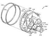
도 18은 도 11에서 도시된 상기 수전력 발전 시스템에 포함되는 내측 하우징의 분해 사시도(exploded perspective view)를 도시한다.FIG. 18 shows an exploded perspective view of the inner housing included in the hydro power generation system shown in FIG. 11.
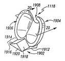
도 19는 도 11에서 도시된 상기 수전력 발전 시스템에 포함되는 패들의 사시도를 도시한다.FIG. 19 illustrates a perspective view of a paddle included in the hydro power generation system illustrated in FIG. 11.
도 20은 라인 20-20을 따라 취해지는 도 19에서 도시된 상기 패들의 단면도를 도시한다.20 shows a cross-sectional view of the paddle shown in FIG. 19 taken along lines 20-20.
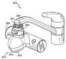
도 21은 배관 고정장치를 포함하는 수전력 발전 시스템의 사시도를 도시한다.21 shows a perspective view of a hydro power generation system including a plumbing fixture.
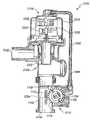
도 22는 도 21에서 도시되는 상기 배관 고정장치의 단면의 측면도를 도시한다.FIG. 22 shows a side view of a cross section of the plumbing fixture shown in FIG. 21.
도 23는 도 22의 상기 배관 고정장치에 포함되는 전력 제어기 예의 개략적인 다이어그램을 도시한다.FIG. 23 shows a schematic diagram of an example of a power controller included in the plumbing fixture of FIG. 22.
도 24는 도 22의 상기 배관 고정장치에 포함되는 전력 제어기의 또 다른 예의 개략적인 다이어그램을 도시한다.FIG. 24 shows a schematic diagram of another example of a power controller included in the pipe fixing device of FIG. 22.
도 25는 도 21-24의 상기 배관 고정장치 내의 상기 수전력 발전 시스템의 동작을 도시하는 프로세스 흐름 다이어그램이다.FIG. 25 is a process flow diagram illustrating operation of the hydro power generation system in the plumbing fixture of FIGS. 21-24.
도 26은 상기 수전력 발전 시스템의 또 다른 실시 예에 대한 부분 단면의 측면도를 도시한다.FIG. 26 shows a side view of a partial cross section of still another embodiment of the hydro-power generation system. FIG.
도 27은 도 26의 상기 수전력 발전 시스템에 대한 또 다른 단면의 측면도를 도시한다.FIG. 27 shows a side view of another cross section for the hydro-power generation system of FIG. 26.
도 28은 처리 시스템의 투시도.28 is a perspective view of a processing system.
도 29는 도 28에 도시된 처리 시스템의 전개된 투시도.FIG. 29 is an exploded perspective view of the processing system shown in FIG. 28.
도 30은 도 29의 처리 시스템에 포함된 밸브 본체의 투시도.30 is a perspective view of a valve body included in the processing system of FIG. 29.
도 31은 도 29의 처리 시스템에 포함된 매니폴드의 투시도.FIG. 31 is a perspective view of a manifold included in the processing system of FIG. 29. FIG.
도 32는 도 31의 매니폴드의 다른 투시도.32 is another perspective view of the manifold of FIG. 31;
도 33은 도 29에 도시된 처리 시스템에 포함된 매니폴드와 필터 모듈의 투시도.FIG. 33 is a perspective view of a manifold and filter module included in the processing system shown in FIG. 29. FIG.
도 34는 도 29에 도시된 처리 시스템에 포함된 리액터 모듈과 매니폴드의 투시도.FIG. 34 is a perspective view of a reactor module and manifold included in the processing system shown in FIG. 29. FIG.
도 35는 도 34에 도시된 리액터 모듈에 포함된 엘보우의 투시도.FIG. 35 is a perspective view of an elbow included in the reactor module shown in FIG. 34. FIG.
도 36은 제거된 하우징의 부분과 도 28에 도시된 처리 시스템의 투시도.36 is a perspective view of the portion of the housing removed and the processing system shown in FIG. 28.
도 37은도 29에 도시된 처리 시스템의 부분을 도시한 블록도.FIG. 37 is a block diagram illustrating a portion of the processing system shown in FIG. 29. FIG.
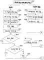
도 38은 도 29에 도시된 처리 시스템의 작동 상태를 도시한 흐름도.FIG. 38 is a flow chart showing an operating state of the processing system shown in FIG. 29; FIG.
도 39는 도 38의 처리 흐름도의 제 2 부분을 도시한 도면.FIG. 39 shows a second part of the processing flowchart of FIG. 38;
상기 발명의 예시적인 실시 예는 특정한 구성에 관하여 아래에서 설명되고, 당업자는 상기 청구항의 범위를 유지하면서 다양한 변화 및 수정이 상기 특정한 구성에 만들어질 수 있다는 것을 인식할 것이다. 본 바람직한 실시 예는 물 흐름을 포함하고, 전력 공급을 요구하는 임의의 시스템과 함께 이용될 수 있다. 그러나 상기 실시 예는 주거용 또는 휴대용 사용을 위한 수처리 시스템, 배관 고정장치 등과 같은 시스템에 대하여 디자인된다. 당업자는 또한 상기 실시 예가 물 이외의 유체 와 함께 이용될 수 있고, “물”및 “수”라는 용어의 사용이 제한으로서 해석되지 않는다는 것을 알 것이다.Exemplary embodiments of the invention are described below with respect to particular configurations, and those skilled in the art will recognize that various changes and modifications can be made to the specific configurations while maintaining the scope of the claims. The present preferred embodiment includes a water flow and can be used with any system that requires power supply. However, the embodiment is designed for systems such as water treatment systems, plumbing fixtures, etc. for residential or portable use. Those skilled in the art will also appreciate that the above embodiments may be used with fluids other than water, and that the use of the terms “water” and “water” is not to be construed as limiting.
도 1은 선호되는 수전력 발전 시스템(12)과 연결된 수처리 시스템(10)의 측면도를 도시한다. 이 실시 예에서, 상기 수전력 발전 시스템(12)은 노즐(14), 하우징(16), 임펠러(impeller)(18) 및 하우징 아웃릿(20)를 포함한다. 상기 노즐(14)은 도관(22)에 의해 상기 수처리 시스템(10)과 결합된다. 상기 도관(22)은 PVC 플라스틱 또는 유사한 물질로 형성될 수 있고, 스레드 연결(threaded connection), 마찰 핏(fit) 또는 몇몇 다른 유사한 연결 메커니즘에 의해 상기 노즐(14)에 결합될 수 있다.1 shows a side view of a
동작 중에, 가압된 물은 상기 수처리 시스템(10)으로부터 화살표(24)에 의해 도시되는 것처럼 상기 노즐(14)을 경유하여 상기 수전력 발전 시스템(12)으로 흐른다. 상기 노줄(14)은 물이 상기 노즐(14)을 통해 흐르고, 상기 하우징(16)을 통해 상기 하우징 아웃릿(20)으로 강요되도록 상기 하우징(16)과 결합된다. 대안적인 실시 예에서, 상기 수전력 발전 시스템(12)은 상기 수처리 시스템(10) 내에 위치될 수 있거나, 또는 상기 물이 수처리 시스템(10)으로 들어가기 전에 가압된 물의 공급을 수용하도록 위치될 수 있다.In operation, pressurized water flows from the
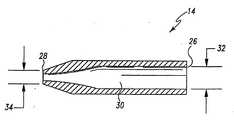
도 2는 상기 노즐(14)의 한 실시 예에 대한 단면을 도시한다. 상기 선호되는 노즐(14)은 음속 노즐(sonnic nozzle)인데, 그것을 통하여 흐르는 가압된 물의 속도가 증가한다. 이 실시 예에서, 상기 노즐(14)은 스테인리스 스틸 또는 몇몇 다른 유사한 단단한 물질로 형성되고, 노즐 입구(26) 및 노즐 출구(28)를 포함한다. 상 기 노즐 입구(26)는 이전에 설명된 상기 수처리 시스템(10)에 결합된다. 상기 노즐 출구(28)는 상기 하우징(16)에 결합되는데, 상기 결합은 그들 사이에 물샐틈없는 연결을 형성하는 것이 가능한 마찰 핏(fit), 스냅-핏(snap-fit), 스레드 연결 또는 다른 유사한 결합 메커니즘에 의해 이루어진다. 상기 노즐(14)은 차후에 설명될 상기 임펠러(18)를 갖는 상기 노즐(14)의 적절한 정렬을 제공하는 어떤 위치에서 상기 하우징(16)을 관통할 수 있다.2 shows a cross section of one embodiment of the
상기 노즐(14)은 통로(30)를 포함하는데, 상기 통로는 그것을 통해 물 흐름을 제공한다. 상기 통로(30)는 상기 노즐 입구(26)의 제1 사전에 결정된(predetermined) 직경(32) 및 상기 노즐 출구(28)의 제2 사전에 결정된 직경을 갖도록 형성된다. 이 실시 예에서, 상기 제2 사전에 결정된 직경(34)은 상기 제1 사전에 결정된 직경(32)의 약 26퍼센트이다. 상기 통로(30)는 상기 노즐(14)의 사전에 결정된 길이에 대하여 상기 제1 사전에 결정된 직경(32)을 유지한다. 상기 통로(30)의 남아있는 부분은 상기 통로(30)를 상기 제2 사전에 결정된 직경(34)까지 균일하게 가늘게 함으로써 원뿔형 형상이 된다. 이 실시 예에서, 상기 노즐(14)의 통로(30)는 상기 제1 사전에 결정된 직경(32) 및 상기 제2 사전에 결정된 직경(34) 사이에 대략 18도 각으로 가늘어진다.The
상기 통로(30)의 구조는 상기 노즐(14)로부터 빠져나오는 물의 속도를 결정한다. 또한 상기 노즐 출구에서 상기 물의 속도는 상기 물 소스의 압력 및 상기 노즐(14)의 백 프레셔(back pressure) 하향흐름(downstream)에 의존한다. 상기 노즐 출구(28)에서 사전에 결정된 바람직한 상기 속도의 범위는 상기 노즐 입구(26)에서 상기 수처리 시스템(10)(도 1에서 도시됨)에 의해 제공되는 예상되는 압력 범위를 이용하여 결정될 수 있다. 예를 들면, 가정의 물 시스템에서, 상기 물 공급의 압력은 스퀴어 인치(square inch)당(PSI) 약 20에서 40 파운드의 범위에 있다. 상기 통로(30)는 또한 상기 노즐 출구(28)에 연속적이고 균일한 물의 흐름을 제공한다. 동작중에 상기 노즐(14)을 통해 흐르는 물은 사전에 결정된 속도의 범위 내에서, 사전에 결정된 궤적을 가지고 상기 하우징(16) 속으로 흐른다.The structure of the
도 1을 다시 참조하면, 상기 하우징(16)은 단단한 물 통로를 형성할 수 있는 플라스틱 또는 몇몇 다른 유사한 방수 물질로 구성되는 도관을 형성한다. 이 예에서, 상기 하우징(16)은 상기 하우징(16)의 내측을 볼 수 있도록 도 1에서 도시한 반투명한 부분을 포함한다. 상기 하우징(16)은 상기 물이 상기 노즐 출구(28)을 빠져나온 후에 상기 하우징(16)을 통해 흐를 때 유체상태로 물과 통신하는 상기 임펠러(18)를 포함하도록 형성된다.Referring again to FIG. 1, the
상기 임펠러(18)는 허브(44)에 단단하게 묶인 다수의 날(blades)(42)을 포함한다. 상기 날(42)은 상기 노즐(14)로부터 흐르는 물이 사전에 결정된 각으로 상기 임펠러(18)의 날(42)에 부딪치도록 상기 하우징(16) 내에 위치된다. 상기 사전에 결정된 각은 상기 노즐 입구(26)에서 예상되는 수압, 상기 노즐 축구(28)에서의 백 프레셔 및 상기 임펠러(18)의 요구되는 분당회전수(RPM)를 바탕으로 하여 결정된다. 동작중에, 상기 흐르는 물은 상기 임펠러(18)에 작용하여, 그것이 상기 하우징 내에 단일 방향으로 회전하도록 한다. 아래에서 자세히 설명되듯이, 상기 임펠러(18)가 회전함에 따라, 상기 수전력 발전 시스템(12)의 이 실시예는 흐르는 물의 에너지를 회전 에너지로 전환하고, 그 다음에 그것은 전기로 전환된다. 이 실시 예에서, 상기 임펠러(18)는 상기 하우징(16)을 통해 흐르는 물에 잠긴다.The
도 3은 절단된 상기 하우징(16)의 한 부분이 90도 회전된, 도 1에서 도시된 실시 예를 나타낸다. 도시된 것처럼, 상기 임펠러(18)는 종축으로 뻗어있는 샤프트(shaft)(48)에 의해 발전기(46)에 동축으로 고정되어 있다. 상기 샤프트(48)는 상기 임펠러(18)에 고정되어 연결된 스테인리스 또는 몇몇 다른 유사한 단단한 물질이 될 수 있다. 상이 임펠러(18)의 허브는 상기 샤프트(48)의 한 단부에 동축으로 연결되어 있고, 상기 발전기(46)의 부분인 발전기 샤프트(50)는 동축으로 다른 단부에 연결되어 있다. 상기 임펠러(18) 및 상기 발전기(46)에 상기 샤프트(48)의 단단한 연결은 용접, 압력-핏(press-fit) 또는 다른 유사한 단단한 연결에 의해 이루어질 수 있다.FIG. 3 shows the embodiment shown in FIG. 1 in which a portion of the
상기 회전 가능한 샤프트(48)는 고무 또는 다른 유사한 물질로 만들어지는 상기 물샐틈없는 밀봉(52)을 통해 상기 하우징(16)을 관통하여 종축으로 확장한다. 상기 물샐틈없는 밀봉(52)은 상기 하우징(16)에 결합되고, 상기 샤프트(48)가 상기 하우징(16)내로부터 물의 탈출 없이 자유로운 회전이 가능하도록 형성된다. 상기 샤프트(48)는 상기 하우징(16)에 인접하여 위치한 상기 발전기(16)로 종축으로 확장한다. 비록 도시되지 않았지만, 상기 발전기(46)의 외측 표면은 예를 들면, 너트와 볼트, 리벳 또는 상기 하우징(16) 및 발전기(46)에 단단하게 결합 가능한 다른 유사한 메커니즘에 의해 상기 하우징(16)에 결합될 수 있다.The
동작 중에, 상기 하우징(16)을 통해 물이 흐르고, 상기 임펠러(18)가 회전함 에 따라, 대응하는 샤프트(48, 50)가 회전하며, 상기 발전기(46)로부터 전기가 생산되도록 한다. 대안적인 실시 예에서, 자기 결합기(magnetic coupler)(도시되지 않음)가 상기 하우징(16)을 관통할 필요성을 없애기 위해 상기 샤프트(48)를 대신하여 이용된다. 이 실시 예에서, 상기 임펠러(18)는 상기 하우징(16) 밖의 상기 발전기 샤프트(50)에 위치된 유사한 자석과 단단하게 결합되도록 충분한 자기 강도를 가진 자석을 포함한다. 동작중에, 상기 임펠러(18)가 회전할 때, 상기 임펠러를 향한 자석 및 상기 발전기 샤프트(50)를 향한 자석의 자기 인력(magnetic attraction)은 상기 발전기 샤프트(50)의 회전을 일으키고, 그 때문에 상기 발전기(46)로부터 전기가 발생된다.In operation, as water flows through the
이 실시 예에서, 상기 발전기(46)는 교류(AC)를 발생할 수 있는 영구 자석 발전기가 될 수 있다. 상기 교류(AC)는 직류(DC)를 생산하도록 정류될 수 있다. 대안적인 실시 예에서, 상기 발전기(46)는 AC 및 DC 전류 둘 다를 생산할 수 있다. 상기 전류는 도선, 모선(busses) 또는 전기를 통하게 할 수 있는 다른 유사한 물질이 될 수 있는 다수의 도체(54)에 의해 상기 발전기(46)로부터 전송된다. 생산되는 상기 전기의 전압 레벨은 상기 임펠러(18)의 분당회전수의 함수이다. 앞에서 설명했듯이, 상기 노즐(14)로부터 흐르는 물의 속도는 사전에 결정된 범위내로 디자인되고, 그것에 의해 상기 발전기(46)에 의해 발생되는 전기의 출력 전압을 제어한다.In this embodiment, the
이 실시 예에 의해 생산되는 상기 교류 및 정류된 직류는 상기 수처리 시스템(10)에 전력을 공급하기 위해 이용될 수 있고, 또한 예를 들면, 배터리 또는 커 패시터 같은 에너지 저장 디바이스(도시되지 않음)를 충전하기 위해 이용될 수 있다. 상기 임펠러(18)의 회전 또는 생산되는 전기의 지속은 흐름율(flow rate) 또는 상기 수처리 시스템(10)을 통해 흐르는 물의 양 같은 흐름을-바탕으로 하는 측정을 위한 메커니즘을 제공할 수 있다. 상기 임펠러(18)의 회전 또는 생산되는 전기의 지속은 상기 흐름을-바탕으로 하는 측정을 제공하도록 상기 발전기(46)의 백(back) 전자기력(EMF)과 결합될 수 있다. 당업자는 상기 수전력 발전 시스템(12)이 또한 상기 수처리 시스템(10) 이외의 다른 시스템에 이용될 수 있다는 것을 인식할 것이다.The alternating current and rectified direct current produced by this embodiment may be used to power the
도 4는 상기 수전력 발전 시스템(12)의 또 다른 실시 예의 단면도를 도시한다. 이 실시 예는 도 1에서 도시된 상기 실시 예에서처럼, 상기 수처리 시스템(10)에 유사하게 결합되고, 노즐(14), 하우징(16), 임펠러(18) 및 하우징 출구(20)를 포함한다. 앞에서 설명한 실시 예와 유사하게, 상기 노즐(14)은 회전 가능한 임펠러(18)를 향하는 고속의 물을 제공한다. 그러나 이 실시 예에서, 상기 임펠러(18)는 동작 중에 상기 하우징(16) 내의 물에 잠기지 않는다. 그것에 있어서, 상기 노즐(14)로부터의 물은 상기 임펠러(18)를 향하는 흐름을 형성한다.4 shows a cross-sectional view of another embodiment of the hydro-
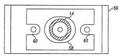
상기 노즐(14)은 도 2에서 도시되고, 앞에서 설명된 노즐(14)과 유사한 음속 노즐(sonic nozzle)이 될 수 있다. 상기 노즐(14)은 상기 하우징(16)을 관통하고, 장착 플레이트(plate)(56)에 의해 거기에 결합된다. 상기 장착 플레이트(56)는 상기 하우징(16)의 외측 표면에 근접하여 위치된다. 당업자는 상기 하우징(16)에 상기 노즐(14)을 결합하기 위해 이용되는 다른 방법들이 존재한다는 것을 인식할 것 이다.The
도 5는 이 실시 예의 장착 플레이트(56)에 장착되는 상기 노즐(14)의 단면도를 도시한다. 상기 장착 플레이트(56)는 종축의 홈(slot)(56) 및 상기 노즐(14)을 상기 임펠러(18)와의 관계에서 적당한 위치로 조절하는 한 쌍의 이어(ears)(60)를 포함한다. 이 실시 예에서, 상기 노즐(14)은 상기 이어(60)에 스레드 나사(threaded screws)를 주입함으로써 상기 적당한 위치가 달성된 때에, 상기 하우징(16)에 단단하게 장착될 수 있다. 대안적인 실시 예에서, 예를 들면 스레드 나사, 리벳 또는 핀 같은 패스너(fastener)가 상기 하우징(16)에 있는 상기 장착 플레이트(56)를 단단하게 장착할 때, 상기 장착 플레이트(56)는 상기 노즐(14)에 대한 하나의, 사전에 결정된, 요구되는 위치를 제공한다.5 shows a cross-sectional view of the
다시 도 4를 참조하면, 상기 노즐(14)의 요구되는 위치는 상기 노즐(14)이 상기 하우징(16) 속으로 종축으로 확장하도록 이루어진다. 이 실시 예의 상기 하우징(16)은 도 4에서 도시되듯이 상기 하우징(16)의 내측 벽에 의해 규정되는 하우징 공동(62)을 포함한다. 상기 하우징 공동(62)은 그 안에 위치된 상기 임펠러(18)를 포함하는 에어 공간(air space)이다. 동작 중에, 물은 사전에 결정된 각으로 상기 임펠러(18)에 부딪치는 사전에 결정된 궤적을 가지고 상기 노즐(14)로부터 상기 하우징 공동(62)으로 방출된다. 상기 사전에 결정된 각은 상기 임펠러(18)의 요구되는 RPM 및 상기 수처리 시스템(10)으로부터 상기 노즐(14)로 공급되는 물의 압력 범위에 바탕을 두고 있다. 상기 노즐(14) 및 상기 임펠러(18)의 협력적인 동작은 가압된 물과의 동작에 제한되지 않고, 공기와 같은 다른 유체가 유사하게 이용될 수 있다.Referring again to FIG. 4, the required position of the
도 4에서 추가로 도시되는 것처럼, 상기 임펠러(18)는 다수의 날(64)을 포함한다. 이 실시 예의 상기 날(64) 각각은 한쪽 단부에서 임펠러 허브(66)에 단단하게 결합되고, 반대쪽 단부에 형성되는 패들(68)을 포함한다. 상기 임펠러 허브(66)는 앞에서 설명한 실시 예에서처럼 샤프트(48)에 단단하게 연결된다. 당업자는 상기 날(64)의 양 및 상기 임펠러(18)의 크기가 상기 응용에 의존하며 변할 수 있다는 것을 인식할 것이다.As further shown in FIG. 4, the
도 6은 도시적 목적을 위해 절단되는 상기 하우징(16)의 부분을 90도 회전한, 도 5에서 도시된 수전력 발전 시스템(12)의 실시 예를 도시한다. 도시된 것처럼, 상기 수전력 발전 시스템(12)은 앞에서 설명한 실시 예에서처럼 상기 샤프트(48)를 가지는 상기 발전기(46)에 결합된 상기 하우징(16)을 포함한다. 또한 회전 가능한 상기 샤프트(48)는 상기 임펠러(18)로부터 상기 물샐틈없는 밀봉(52)을 통해 상기 발전기(46)로 종축으로 확장한다. 대안적인 실시 예에서, 상기 샤프트(48)는 앞에서 기술된 자기적 결합기에 의해 수정될 수 있고, 그것에 의하여 상기 하우징(16)의 관통 및 상기 물샐틈없는 밀봉(52)을 제거하게 된다. 도시된 것처럼, 상기 샤프트(48)는 상기 패들(68)을 포함하는 상기 하우징 공동(62)내의 상기 에어 공간에 상기 임펠러(18)를 회전가능하게 위치시킨다.FIG. 6 shows an embodiment of the hydro-
도 6에서 도시된 것처럼, 이 실시 예의 상기 패들(68) 각각은 홈(70)을 포함하는 포물선 형상으로 형성된다. 상기 패들(68)의 포물선 형상은 상기 노즐(14)(도 5에서 도시됨)로부터 방출되는 상기 물에 존재하는 에너지의 균일한 수신 기(receiver)를 제공한다. 상기 홈(70)은 상기 임펠러(18)가 회전함에 따라 상기 방출된 물의 에너지가 상기 다음 패들(68)로 통과하도록 한다. 상기 다음 패들(68)로 상기 방출된 물 에너지의 순간적인 통과는 상기 물로부터 상기 임펠러(18)로 상기 에너지 전송의 효율을 최대화한다. 대안적인 실시 예에서, 상기 날(64)은 상기 노즐(14)로부터 방출되는 다른 유체로부터 효율적인 에너지 전송에 도움이 되는 구조 및 다른 형상으로 형성된다. 예를 들면, 상기 유체가 공기일 때, 상기 날(64)은 베인(vane), 핀(fin) 또는 상기 흐르는 공기로부터의 에너지를 상기 임펠러(18)의 회전으로 변환하는 다른 유사한 구조로서 형성될 수 있다.As shown in FIG. 6, each of the
동작 중에, 상기 물의 흐름이 사전에 결정된 각으로 상기 임펠러(18)에 부딪친 후에, 상기 물은 화살표(72)로 나타내는 것처럼 상기 하우징 출구(20)를 향하여 중력에 의해 떨어진다. 그것에 있어서, 상기 물은 상기 하우징 출구(20)에서 수집되며, 그것에 의하여 상기 하우징(16) 밖으로 전달된다. 상기 임펠러(18)가 물에 잠기지 않기 때문에, 상기 물 흐름으로부터 상기 임펠러(18)로 전송되는 대부분의 에너지가 상기 샤프트(48)에 회전력으로서 제공된다.In operation, after the flow of water impinges the
상기 샤프트(48)의 회전은 상기 발전기(46) 부분에 대한 회전을 일으킨다. 상기 발전기(46)의 한 실시 예는 발전기 하우징(82) 내에 위치되는 회전자(76), 제1 고정자(78), 및 제2 고정자(80)를 포함한다. 상기 회전자(76)는 상기 샤프트(48)에 단단하게 결합되고, 그것과 함께 회전한다. 상기 제1 및 제2 고정자(78, 80)는 상기 발전기 하우징(82)에 단단하게 결합되고, 상기 샤프트(48)를 주위에서 둘러싼다. 상기 회전자(76)는 발전기(46)를 형성하기 위하여 상기 제1 및 제2 고정자(78, 80) 사이에 위치된다.Rotation of the
이 실시 예의 상기 회전자(76)는 다수의 영구 자석(84)을 포함하는 디스크 형태가 될 수 있다. 상기 영구자석(84)은 상기 제1 및 제2 고정자(78, 80)와 협력적으로 동작하도록 상기 회전자(76) 내의 사전에 결정된 위치에 균일하게 배열된다. 이 실시 예에서 각각의 상기 제1 및 제2 고정자(78, 80)는 또한 다수의 코일(86)을 포함하는 디스크를 형성할 수 있다. 상기 코일(86)은 상기 영구 자석(84)과 협력적으로 동작하도록 상기 제1 및 제2 고정자(78, 80) 내에 균일하게 위치된다. 상기 코일(860은 전기를 발생하도록 조작이 가능한 하나 이상의 권선을 형성하도록 전기적으로 연결될 수 있다. 극(pole)의 수 및 상기 제1 및 제2 고정자(78, 80)의 디자인은 다수의 요소에 의존한다. 상기 요소는 상기 영구자석(84) 및 상기 백 EMF 에 의해 형성되는 가우스 필드(gaussian field)의 강도뿐만 아니라 상기 발전기의 요구되는 출력 전력 및 요구되는 RPM을 포함한다.The
이 실시 예에서, 상기 회전자(76)의 회전은 상기 영구자석(84)에 의해 발생되는 자기 플럭스가 유사하게 회전하도록 한며, 그것에 의해 상기 제1 및 제2 고정자(78, 80)에서 전기를 생산한다. 상기 회전자(76) 및 상기 제1 및 제2 고정자(78, 80)는 교류(AC)를 발생하기 위해 협력적으로 동작한다. 상기 AC는 AC 및 직류(DC) 모두 공급하도록 상기 발전기(46)에 의해 안정화되고 정류될 수 있다. 대안적인 실시 예에서, 상기 영구 자석(84)은 상기 발전기(46)가 직류(AC)를 발생하도록 상기 제1 및 제2 고정자(78, 80) 상에 위치될 수 있다. 또 다른 대안적인 실시 예에서, 상기 발전기(46)는 도 3에서 설명된 발전기(46)와 유사한다.In this embodiment, the rotation of the
동작 중에, 가압된 물은 상기 수처리 시스템(10)(도 1에 도시됨)에서 상기 수전력 발전 시스템(12)으로 공급될 수 있다. 이전의 실시 예에서처럼, 상기 수전력 발전 시스템의 대안적인 실시 예는 물을 상기 수처리 시스템(10)으로 공급할 수 있거나, 또는 상기 수처리 시스템(10) 내에 위치될 수 있다. 이 실시 예에서, 앞에서 설명한 것처럼 물은 상기 수처리 시스템(10)으로부터 상기 노즐(14)로 공급된다.In operation, pressurized water may be supplied from the water treatment system 10 (shown in FIG. 1) to the hydro
가압된 물은 상기 노즐(14)을 통해서 흐르고, 상기 하우징 공동(62)으로 고속으로 배출되며, 그것에 의해 사전에 결정된 입사각으로 상기 임펠러(18)의 패들에 부딪친다. 상기 물이 상기 패들(68)에 부딪칠 때, 상기 방출된 물의 에너지가 상기 임펠러(18)로 전달되고, 단일 방향으로 회전을 일으킨다. 상기 임펠러(18)가 회전함에 따라, 상기 방출된 물 흐름의 부분도 또한 상기 홈(70)을 통해 흐르고, 상기 임펠러(18)의 다른 패들(68)에 부딪친다. 상기 패들(68)과 상기 물의 충돌 및 동반하는 에너지 전달 이후에, 상기 물은 중력에 의해 상기 하우징 출구(20)로 떨어지고, 상기 하우징(16) 밖으로 흐른다. 따라서 상기 하우징 공동(62)은 동작 중에 에어 공간을 유지하고, 동작 중에 물로 완전히 채워지지 않는다.Pressurized water flows through the
상기 임펠러(18)의 회전은 상기 샤프트(48)의 회전을 일으키고, 그것에 의해 상기 발전기(46)의 회전자(76)를 회전시킨다. 이 실시 예에서, 상기 회전자(76)는 약 2400 분당회전수(RPM)로 회전한다. 상기 회전자(76)의 회전은 상기 수처리 시스템(10)으로 공급되는 전기의 발생을 유도한다. 앞에서 설명하였듯이, 상기 발전기(46)에 의해 생산되는 전압 레벨의 범위는 상기 노즐(14)을 통해 흐르는 상기 물 의 속도 범위에 바탕을 두고 있다. 따라서 상기 노즐(14)을 통해 흐르는 물에 대하여 사전에 결정된 속도 범위를 선택함으로써 상기 발전기의 상기 전압 범위가 선택될 수 있다.Rotation of the
도 7은 상기 수처리 시스템(10)에 우선적으로 결합되는 상기 수전력 발전 시스템(12)의 또 다른 실시 예의 단면도를 도시한다. 도시된 것처럼, 상기 수전력 발전 시스템(12)은 회전자 하우징(102) 및 고정자 하우징(104)를 포함한다. 상기 회전자 하우징(102)은 플라스틱 또는 다른 유사한 단단한 물질로 구성될 수 있는 도관을 형하고, 입구(106) 및 출구(108)를 포함한다. 동작 중에 상기 입구(106)는 화살표(110)에 의해 도시되는 것처럼 상기 흐르는 물을 수용하고, 상기 출구(108)는 상기 흐르는 물을 상기 수처리 시스템(10)으로 흐르게 한다. 대안적인 실시 예에서, 상기 수전력 발전 시스템(12)은 상기 수처리 시스템(10) 내에 위치될 수 있거나, 또는 상기 수처리 시스템(10) 밖으로 흐르는 물을 수용하도록 위치될 수 있다. 앞에서 설명한 것처럼, 상기 수전력 발전 시스템(12)을 통한 물의 흐름은 상기 수처리 시스템(10)에 의해 제어될 수 있다.FIG. 7 shows a cross-sectional view of another embodiment of the hydro
도 7에서 도시되는 것처럼, 상기 회전자 하우징(102)은 회전자(112)를 포함하고, 상기 고정자 하우징(104)은 고정자(114)를 포함한다. 이 실시 예의 회전자(112)는 6개의 북/남 극 조합을 가지는 12극 영구 자석이 될 수 있다. 아래에서 자세히 설명되는 것처럼, 이 실시 예의 상기 고정자(114)는 8개의 북/남 극 조합을 가지도록 디자인된 고리모양의 링(ring)이 될 수 있다. 상기 회전자(112) 및 고정자(114)는 동작 중에 전기를 생산하기 위해 협력적으로 동작한다. 상기 기술 분야 에서 알려진 것처럼, 고정자는 상기 출력에서 요구되는 상기 전압의 크기에 의존하면서 임의의 수의 극을 포함하도록 배열될 수 있는 고정 권선을 포함한다. 본 실시 예에서 공개된 상기 권선에서 극의 수는 본 발명의 제한으로서 간주되지 않아야 한다.As shown in FIG. 7, the
도 8은 도시적 목적을 위해 절단된 상기 고정자 하우징(104)의 상단 부분에 대한 도 7에서 도시된 상기 실시 예의 정면도를 도시한다. 상기 고정자(114)는 상기 회전자 하우징(102)을 주위에서 둘러싸도록 상기 고정자 하우징(104) 내에 단단하게 위치된다. 상기 고정자(114)는 코어(core)(116), 다수의 돌출한 극(118) 및 다수의 코일(120)을 포함한다. 상기 코어(116)는 철, 스틸 또는 다른 유사한 물질로 구성될 수 있으며, 상기 돌출된 극(118)을 포함하도록 형성될 수 있다. 이 실시 예에서, 각각 코일(120)에 의해 둘러싸이는 8개의 돌출한 극(118)이 있을 수 있다.8 shows a front view of the embodiment shown in FIG. 7 of the top portion of the
상기 돌출한 극(118)은 그들이 상기 회전자 하우징(102)을 주위에서 둘러싸도록 상기 고정자(114) 상에 형성될 수 있다. 각각의 상기 돌출된 극(118)은 상기 기술 분야에서 폴슈(pole shoe)로 알려진 정렬된 단부(formed end)를 포함한다. 상기 폴슈(122)는 상기 회전자 하우징(102)에 인접하여 위치된다. 상기 폴슈(122)는 상기 회전자(112)에 의해 형성되는 일정한 자기 플럭스를 상기 코일(120)을 통해 전도한다. 상기 코일(120)은 도선 또는 전기를 전도할 수 있고, 상기 돌출한 극(118) 주위를 감쌀 수 있는 다른 유사한 물질이 될 수 있다. 비록 도시되지 않았지만, 상기 코일(120)은 상기 권선을 형성하도록 전기적으로 연결된다. 상기 발명분야에서 알려진 것처럼 각각의 코일(120)에 대해 이용되는 도선의 회전수는 상기 전압 및 전력 필요, 상기 회전자(112)의 최소 및 최대 회전수, 최대 허용가능 백 프레셔, 상기 요구되는 인덕턴스 및 상기 자기 가우스(magnetic gauss)에 의해 결정된다.The protruding
도 7을 다시 참조하면, 상기 고정자(114)는 상기 회전자 하우징(102)의 중심축에 수직인 가로로 위치한다. 상기 고정자(114)가 상기 회전자 하우징(102) 밖에 위치되므로, 그것은 상기 회전자 하우징(102) 내에 흐르는 상기 물과의 유체 통신(fluid communication)으로부터 고립된다. 상기 고정자 하우징(104)은 상기 회전자 하우징(102)에 단단하게 결합되고, 그에 의하여 상기 고정자(114)를 위해 상기 회전자 하우징(102) 상에 사전에 결정된 위치를 제공한다. 이 실시 예에서, 상기 고정자 하우징(104)은 마찰 핏(friction fit)에 의해 상기 회전자 하우징(102)의 외부 표면과 결합된다. 당업자는 상기 회전자 하우징(102) 및 상기 고정자 하우징(104)을 결합하는 다양한 다른 방법이 존재한다는 것을 인식할 것이다.Referring back to FIG. 7, the
상기 수전력 발전 시스템(12)의 이 실시 예에서, 상기 회전자(112)는 금속, 소결된 금속(sintered metal), 분출된 금속(extruded metal), 플라스틱 주입 또는 세라믹 물질로 형성될 수 있는 영구 자석(124)을 포함한다. 상기 영구자석(124)은 일정한 자기 플럭스를 형성하고, 회전자 샤프트(126)에 결합된다. 회전할 수 있는 상기 회전자 샤프트(126)는 상기 영구자석(124)의 반대쪽 단부로부터 종축으로 연장되고, 스테인리스 스틸 또는 다른 단단하고, 부식 저항 물질로 구성될 수 있다. 상기 영구자석(124)은 상기 회전자 샤프트(126)와 동축인 그것의 중심축을 가지고 형성될 수 있다. 상기 영구 자석(124)의 외측 표면은 하나 이상의 회전자 날(128) 포함하도록 유선형으로 형성될 수 있다. 이 실시 예의 상기 영구자석(124)은 상기 회전자 날(128)을 형성하는 단일 나선형 마루(ridge)를 가지는 배럴(barrel) 형상으로 형성된다. 대안적인 실시 예에서, 상기 회전자 날(128)은 터빈 날(turbine blade) 또는 흐르는 물에 종속되어 상기 회전자(112)의 회전을 유도할 수 있는 다른 유사한 디바이스가 될 수 있다.In this embodiment of the hydro-
도 7에서 도시되는 것처럼, 상기 회전자(112)는 상기 회전자 하우징(102)의 중심축과 동축으로 상기 회전자 하우징(102) 내에 위치된다. 상기 회전자(112)에 있는 상기 회전자 샤프트(126)의 한 단부는 제1 칼라(collar)(130)에 주입되고, 상기 회전자 샤프트(126)의 다른 단부는 제2 칼라에 주입된다. 이 실시 예에서, 상기 회전자 샤프트(126)의 단부는 상기 제1 칼라(130) 및 상기 제2 칼라(132)에 고정하는 것을 용이하게 하는 단단한 구를 형성하도록 직경이 증가한다. 상기 제1 칼라(130) 및 제2 칼라(132)는 플라스틱 또는 다른 유사한 물질로 형성되고, 상기 회전 하우징(102)의 중심축에 수직인 가로방향 버팀목(strut)을 생성한다. 상기 제1 칼라(130) 및 상기 제2 칼라(132)는 각각 베어링(134) 또는 상기 회전자 샤프트(126)가 자유롭게 회전하도록 하는 다른 유사한 디바이스를 포함한다. 추가적으로, 상기 제1 칼라(130) 및 상기 제2 칼라(132)는 상기 회전자(112)가 그들 사이에 매달릴 수 있도록 서로로부터 사전에 결정된 거리에서 상기 회전자 하우징(102)에 결합된다.As shown in FIG. 7, the
상기 회전자(112)는 상기 회전자 하우징(102)을 통해 흐르는 물이 상기 회전자(112)의 부분을 형성하는 상기 회전자 날(128)에 도달하도록 상기 회전자 하우 징(102)내에 위치된다. 상기 회전자 날(128)은 패들로서 작용하고, 상기 흐르는 물이 상기 회전자(112)에 작용하도록 한다. 상기 흐르는 물은 상기 회전자(112)가 상기 회전자 하우징(102)의 중심축 둘레를 한 방향으로 회전하도록 한다. 상기 회전자(112)는 상기 회전자(112)의 축이 상기 고정자(114)의 축과 중심을 공유하도록 상기 고정자(114) 내에 위치된다. 상기 회전자(112)는 상기 발전기를 형성하기 위해 상기 고정자(144)와 협력적으로 동작한다.The
동작 중에, 물이 흐르고, 상기 회전자(112)가 회전함에 따라, 상기 회전자(112)에 의해 발생되는 일정한 자기 플럭스 또한 회전하고, 상기 고정자 속으로 관통하며, 그것에 의해 본질적으로 전력을 생산한다. 특정한 거리의 공기 갭(gap)이 상기 회전자(112)로부터의 상기 일정한 자기 플럭스가 상기 고정자(114)로부터의 전기 발생을 유도하도록 상기 회전자(112) 및 상기 고정자(114) 사이에 유지되어야 한다. 이 실시 예에서, 상기 회전자(112)의 영구 자석(124) 및 상기 고정자(114)의 폴슈(122) 사이의 “공기 갭”은 흐르는 물 및 상기 회전자 하우징(102)으로 구성된다. 유체의 흐름 및 상기 회전자 하우징(102)은 상기 일정한 자기 플럭스에 영향을 주지 않는다. 따라서 상기 회전하는 회전자(112)로부터의 상기 회전하는 일정한 자기 플럭스는 상기 고정자(114)의 코일(120)로부터 전기의 생산을 유도한다.In operation, as water flows and the
상기 물이 상기 회전자(112)를 회전하게 하면서 상기 회전자 하우징(102)을 통해 흐를 때, 상기 회전하는 일정한 자기 플럭스가 상기 고정자(114)의 권선에 전달되고, 전기가 생산된다. 상기 전기는 도체(54)를 통해서 이 실시 예에서 수처리 시스템(10)인 디바이스에 전력을 공급하도록 흐른다. 도 7 및 8에서 도시되는 이 실시 예의 상기 수전력 발생 시스템(12)은 상기 수처리 시스템(10)에 전력을 공급히기 위해 이용될 수 있는 교류(AC)를 생산한다. 대안적인 실시 예에서, 상기 수전력 발전 시스템(12)은 직류(C)를 생산하기 위해 상기 교류(AC)를 정류할 수 있다. 또 다른 대안적인 실시에서, 상기 수전력 발전 시스템(12)은 상기 교류(AC)를 정류하고, 안정화함으로써 상시 수처리 시스템(10)에 AC 및 DC 모두 공급한다. 상기 DC 전류는 또한 에너지 저장 디바이스(도시되지 않음)를 충전하기 위해 이용될 수 있다. 상기 회전자(112)의 회전 및 전기가 생산되는 기간은 또한 흐름율 또는 상기 수처리 시스템(10)을 통해 흐르는 물의 양 같은 흐름을-바탕으로 하는 측정을 제공하기 위해 이용될 수 있다.When the water flows through the
도 9는 도 7 및 8에서 공개된 이전의 실시 예와 개념적으로 유사한 상기 수전력 발전 시스템(12)의 또 다른 실시 예의 단면도를 도시한다. 이 실시 예는 회전자(112), 고정자(114) 및 하우징(142) 내에 위치한 터빈 노즐(140)을 포함한다. 상기 하우징(142)은 입구(144) 및 출구(146)를 포함하는 도관을 형성한다. 물 또는 몇몇 다른 유체가 화살표(148)에 의해 도시되듯이 상기 입구(144)로 흐를 때, 상기 물은 상기 하우징(142)을 통해 흐르고, 상기 출구(146)에 의해 상기 하우징(142) 밖으로 흐른다. 하나의 실시 예에서, 상기 수전력 발전 시스템(12)은 상기 수처리 시스템(10)에 물을 공급하거나 또는 상기 수처리 시스템을 따르면서, 수처리 시스템(10)(도 1에서 도시됨) 내에 위치될 수 있다.FIG. 9 shows a cross-sectional view of another embodiment of the hydro-
상기 하우징(142)은 플라스틱 또는 물을 흐르게 할 수 있는 유사한 단단한 물질로 형성될 수 있다. 이 실시 예의 상기 하우징(142)은 조립 및 유지를 쉽게 하는 제1 섹션(152) 및 제2 섹션(154)을 포함한다. 상기 제1 및 제2 섹션(152, 154)은 아교질(gluing), 마찰 핏(friction fit), 스레드 연결(threaded connection), 음속 용접(sonic welding) 또는 유사한 단단한 연결을 제공하는 몇몇 다른 수단에 의해 단단하게 결합될 수 있다. 상기 하우징(142)은 그것을 통한 물의 흐름을 위해 통로(156)를 형성한다. 상기 터빈 노즐(140)은 상기 통로(156)내에 단단하게 위치된다.The
이 실시 예의 상기 터빈 노즐(140)은 일반적으로 원뿔 형상이 될 수 있고, 플라스틱 또는 몇몇 다른 유사한 단단한 물질로 형성될 수 있다. 상기 터빈 노즐(140)은 전체적으로 팁(158) 및 다수의 버팀목(160)을 포함하도록 형성될 수 있다. 상기 팁(158)은 상기 통로(156)에 중심을 두고 위치할 수 있으며, 상기 흐르는 물이 상기 하우징(142)의 내측 벽을 향하여 바깥쪽으로 향하게 하는데 기여한다. 상기 버팀목(160)은 예를 들면 마찰 핏, 스냅-핏(snap-fit), 스레드 연결 또는 다른 유사한 단단한 연결에 의해 상기 하우징(142)의 내측 벽에 단단하게 연결된다.The
상기 버팀목(160)은 상기 통로(156) 내의 상기 터빈 노즐(140)을 단단하게 잡고, 물이 상기 하우징(142)을 통해 흐르도록 하는 다수의 도관(162)을 포함한다. 상기 도관(162)의 사이즈는 상기 흐르는 물의 속도를 제어하도록 조정될 수 있다. 도 2에 대해 앞에서 설명한 상기 노즐(14)에서처럼, 사전에 결정된 범위의 속도가 결정될 수 있다. 상기 사전에 결정된 범위의 속도는 상기 입구(144)에서 흐르는 물의 예상되는 압력 범위뿐만 아니라 상기 수전력 발전 시스템(12)의 백프레셔에 바 탕을 두고 있다. 또한 상기 버팀목(160)은 상기 흐르는 물을 인도하는 베인(vane)으로서 작동하도록 사전에 결정된 배열로 향하게 할 수 있다. 상기 흐르는 물은 예를 들면 사전에 결정된 방식으로 상기 회전자(112)에 작용하고, 난류(turbulence)를 제거하고, 압력 강하를 조절하고 또는 동작 효율을 증가하도록 방향지울 수 있다.The shoring 160 includes a plurality of
도 10은 상기 하우징(142)의 제1 섹션(152) 내의 상기 버팀목(160) 및 상기 노즐(140)을 도시하는 도 9의 상기 수전력 발전 시스템(12)의 부분을 잘라낸 정면도이다. 상기 버팀목들(160)은 상기 도관(162)을 형성하도록 상기 노즐(140)의 외측 주위에 서로로부터 4.42 밀리미터(0.174 인치) 정도 떨어진, 결정된 거리(1002)에 위치할 수 있다. 각각의 버팀목(160)은 리딩 단부(leading end)(1004) 및 트레일링 단부(trailing end)(1006)를 포함한다. 버팀목(160)에 근접하여 위치된 상기 리딩 단부(1004)는 입구 덕트(entry duct)를 형성할 수 있고, 버팀목(160)에 근접하여 위치된 상기 트레일링 단부(1006)는 출구 덕트(exit duct)를 형성할 수 있다. 화살표(148)에 의해 지시되는 것처럼, 상기 유체의 흐름은 먼저 상기 리딩 단부(1004)에 도달하고, 상기 입구 덕트로 들어간다. 상기 도관(162) 내에서, 상기 유체는 상기 버팀목(60)의 상기 트레일링 단부(1006)에 도달하기에 앞서서 속도가 증가된다.FIG. 10 is a front view of a portion of the hydro
상기 도관(162)의 폭은 도시되는 것처럼 상기 트레일링 단부를 향하면서 점점 더 좁아질 수 있다. 그것에 있어서, 상기 도관 사이의 단면 영역은 약 10% 에서 20% 정도로 사전에 결정된 양만큼 감소된다. 상기 가압된 유체가 점점 더 좁아지는 도관 속으로 흐르도록 강요될 때, 속도가 증가한다. 상기 도관(162) 사이의 단면 영역에서의 점진적 감소는 상기 흐르는 유체의 속도가 증가되는 동안 백 프레셔를 최소로 만든다. 또한 상기 도관(162) 내에 있는 유체의 비-라미나(non-laminar) 흐름은 상기 점진적으로 좁아지는 도관(162)에 의해 최소로 된다.The width of the
상기 버팀목(160)은 또한 다수의 흐름 스트레이트너(straightners)를 포함할 수 있다. 상기 흐름 스트레이트너(1008)는 비-라미나 프로우를 추가로 최소로 만들기 위해 상기 도관(162)에 포함될 수 있다. 상기 버팀목(160)과 유사하게, 상기 흐름 스트레이트너(1008)는 상기 제1 섹션(152)의 내측 벽에 단단하게 결합될 수 있고, 상기 도관(162) 속으로 연장된다. 상기 흐름 스트레이트너(1008) 예는 몸체(body)(1012)에 결합된 날(1010)을 포함할 수 있다. 상기 날(1010)은 상기 버팀목(160) 각각의 상기 트레일링 단부(1006)를 향하여 상기 리딩 단부(1004)로부터 연장되는 상기 흐름 스트레이트너(1008)의 직선 섹션(straight section)이 될 수 있다. 상기 몸체(1012)는 상기 인접하게 위치한 버팀목(160)의 상기 트레일링 단부(1006)에 의해 형성되는 상기 출구 덕트의 상향으로 사전에 결정된 거리에 위치하는 구형 몸체가 될 수 있다. 다른 예에서, 상기 프로우 스트레이트너(1008)는 상기 유체의 흐름을 규정하고, 상기 도관(1621)을 통한 균일한 흐름을 최대화하는 임의의 다른 유체역학 형상(hydrodynamic shape)이 될 수 있다.The shoring 160 may also include a number of flow straighteners. The
도 10에서 추가로 도시되듯이, 상기 노즐(140)은 압축 영역(compression region)과 다음에 오는 침전 영역(settlement region)(1018)으로 분리될 수 있다. 상기 압축 영역(1016) 내에서, 상기 유체 흐름 방향으로 갑작스런 전이가 일어날 수 있다. 상기 갑작스런 전이는 상기 유체 흐름에서 난류를 증가시킬 수 있다. 상기 제1 섹션(152) 내의 유체 용량의 부피가 감소함에 따라 난류는 증가할 수 있다. 상기 부피가 감소함에 따라, 상기 유체의 속도 및 압축이 증가한다. 상기 압축 영역(1016)에서 부피의 감소는 상기 흐르는 유체의 예상되는 압력 범위를 바탕으로 하여 요구되는 흐름율을 달성하도록 사전에 결정될 수 있다. 상기 압축 영역(1016) 내에서, 상기 흐르는 유체는 난류 및/또는 비-라미나 흐름을 증가시킬 수 있는 상기 하우징(142)의 내측 벽을 향해 밖으로 흐르도록 강요된다.As further shown in FIG. 10, the
상기 침전 영역(1018)은 상기 흐르는 유체 내의 난류가 진정되고, 상기 유체가 보다 많은 라미나 흐름을 가지도록 균일한 부피의 유체 용량을 한 영역에 제공한다. 상기 침전 영역(1018)은 상기 흐르는 유체 내에 투영된 양의 난류를 바탕으로 하여 사전에 결정된 범위가 될 수 있다. 상기 유체의 비-라미나 흐름은 상기 도관(162)에 들어가기 이전에 감소될 수 있다. 상기 도관(162) 내에서, 상기 흐르는 유체의 속도는 더 증가되고, 그 다음에 상기 유체는 상기 회전자(112)를 향하게 된다.The settling zone 1018 provides a uniform volume of fluid capacity in one zone so that turbulence in the flowing fluid is calmed and the fluid has more lamina flow. The settling region 1018 may be in a predetermined range based on the amount of turbulence projected in the flowing fluid. Non-lamina flow of the fluid may be reduced prior to entering the
도 9를 다시 참조하면, 이 실시 예의 상기 회전자(112)는 터빈 회전자(164), 회전자 샤프트(166) 및 영구 자석(168)을 포함한다. 상기 회전자(112)는 상기 통로(156)를 흐르는 물이 상기 하우징(142)의 중심 축(170) 주위로 상기 회전자(112)의 회전을 일으키도록 상기 통로(156) 내에 회전가능하게 위치된다. 상기 회전자(112)의 회전은 상기 흐르는 물이 상기 터빈 회전자(164)에 작용할 때 발생한다. 상기 터빈 회전자(164)는 스테인리스 스틸, 알루미늄, 플라스틱 또는 상기 회전력 및 흐르는 물의 힘에 저항할 수 있는 다른 유사한 단단한 물질로 형성될 수 있다. 상기 터빈 회전자(164)는 하나 이상의 터빈 날(174) 및 몸체(174)를 포함한다.Referring back to FIG. 9, the
상기 터빈 날(172)은 상기 버팀목(160)을 통해 흐르는 물로부터 에너지를 수용하도록 위치된다. 상기 터빈 날(172)은 다수의 베인, 나선 마루 또는 상기 흐르는 물의 에너지를 회전 에너지로 전환할 수 있는 몸체(174)에 형성되는 다른 메커니즘이 될 수 있다. 이 실시 예의 상기 터빈 날(172)은 상기 몸체(174)와 함께 전체적으로 형성되고, 상기 하우징(142)의 내측 벽에 인접하여 위치될 때까지 연장된다. 상기 몸체(174)는 상기 회전자 샤프트(166)의 부분을 주위에서 둘러싸는 공동(174)을 규정하도록 형성될 수 있다.The
상기 하우징(142)의 내측 벽을 고려할 때, 상기 도관(162)의 깊이가 상기 터빈 날(172)의 깊이보다 작다는 것을 주의해야 한다. 상기 깊이 차이는 이후에 설명되듯이 상기 흐르는 물의 회전을 제공한다. 또한 상기 물의 흐름 경로는 상기 고정자(114)를 지나서 실질적으로 직선이다. 상기 흐름 경로의 부피는 또한 상기 흐르는 물의 결정된 압력강하를 제공하는 다음에 오는 보다 큰 도관이 된다. 그래서 상기 흐르는 물은 상기 물이 상기 터빈 날(172)을 통해 흐를 때 상기 회전하는 터빈 날(172)에 상당한 양의 운동 에너지를 방출한다. 상기 터빈 날(172)만이 흐르는 물의 고속 흐름에 있기 때문에, 상기 흐르는 물의 상기 운동 에너지는 상당한 손실 및 비효율 없이 상기 터빈 날(172)에 의해 효율적으로 추출된다.Considering the inner wall of the
상기 회전자 샤프트(166)는 회전가능하고, 상기 터빈 회전자(164)와 함께 종합적으로 형성될 수 있거나, 또는 상기 회전자 샤프트(166)는 압력-핏(press- fit), 스레드 연결 또는 유사한 결합 메커니즘에 의해 거기에 단단하게 결합될 수 있다. 상기 회전자 샤프트(166)는 스테인리스 스틸 또는 상기 영구 자석(168)을 통해 종축으로 연장될 수 있는 다른 유사한 단단한 물질이 될 수 있다. 상기 영구 자석(168)은 분출된 자석(extruded magnet) 또는 플라스틱 주입 자석이 될 수 있다. 택일적으로, 상기 영구 자석은 금속, 소결 금속, 세라믹 물질 또는 자석 성질을 가지는 다른 유사한 물질로 형성될 수 있다. 상기 영구 자석(168)은 마찰 핏, 몰딩(molding) 또는 다른 유사한 메커니즘에 의해 상기 회전자 샤프트(166)에 단단하게 결합될 수 있다. 상기 회전자(112)는 다수의 베어링(178)에 의하여 회전가능하게 유지된다.The
상기 베어링(178)은 상기 영구 자석(168)의 맞은편 단부에 있는 상기 회전자 샤프트(166)의 부분을 주변에서 둘러싼다. 상기 베어링(178)은 탄소 그래파이트(graphite), 테플론, 볼 베어링, 세라믹, 초 고분자량(UHMW) 폴리에틸렌 또는 상기 회전자 샤프트(166)의 회전을 견딜 수 있는 다른 유사한 베어링이 될 수 있다. 또한 상기 흐르는 물은 다음에 기술되듯이 상기 베어링(178)을 냉각하도록 동작될 수 있다. 상기 베어링(178)은 단단하게 결합되고, 상기 고정자(114)에 의해 위치 내에서 유지된다.The bearing 178 surrounds a portion of the
이 실시 예의 상기 고정자(114)는 다수의 출구 가이드 베인(exit guide vane)(180), 핀(182), 다수의 코일(184) 및 캡(186)을 포함한다. 도 9에서 도시되듯이, 상기 고정자(114)는 상기 출구 가이드 베인(180)에 의해 상기 통로(156) 내에 단단하게 위치된다. 상기 출구 가이드 베인(180)은 예를 들면 아교, 마찰 핏, 스냅 핏 또는 유사한 단단한 결합 메커니즘에 의해 상기 하우징(142)의 내측 벽에 단단하게 결합된다. 상기 출구 가이드 베인(180)은 상기 하우징(142)의 내측 벽과 평행하게 종축으로 연장되고, 그것을 통해 물의 흐름에 대한 도관을 제공한다. 상기 출구 가이드 베인(180)은 난류, 공기 방울, 백 프레셔 및 효과적인 동작에 영향을 줄 수 있는 상기 흐르는 물의 다른 유사한 행동을 줄이기 위해 상기 흐르는 물이 상기 출구(146)로 흐르도록 형성된다. 상기 핀(182)은 사기 흐르는 물이 상기 출구(146)로 흐르도록 유사하게 형성된다.The
비록 도시되지 않았지만, 상기 출구 가이드 베인(180)은 상기 중심 축(170)과 중심을 같이하는 나선형 형상 코일(또는 강선(rifling))을 닮은 소용돌이 패턴으로 형성될 수 있다. 상기 출구 가이드 베인(180)은 상기 핀(182) 방향에서 점진적으로 풀리고(un-coil), 결국 상기 중심 축(170)에 실질적으로 평행하게 된다. 이 배열에서, 상기 출구 가이드 베인(180)은 난류를 줄이고, 라미나 흐름을 생성할 수 있다.Although not shown, the
동작 중에, 상기 출구 가이드 베인(180)에 의해 수용되는 유체는 상기 터빈 날(172)의 회전에 의한 소용돌이 경향을 포함할 수 있다. 상기 유체의 상기 소용돌이 경향은 상기 출구 가이드 베인(180)의 소용돌이 패턴과 실질적으로 매치될 수 있다. 따라서 상기 유체는 난류를 일으킬 수 있는 급격한 방향 변화 없이 상기 출구 가이드 베인(180)에 들어간다. 상기 출구 가이드 베인(180)에 의해 흐르는 동안, 상기 유체의 소용돌이 경향은 상기 출구 가이드 베인(180)의 점진적인 풀림에 의해 점진적으로 최소화 될 수 있다. 그러므로 상기 유체는 효과적인 동작을 최대 화하도록 실질적으로 라미나 흐름 상태로 상기 출구 가이드 베인(180)을 떠날 수 있다.In operation, the fluid received by the
상기 코일(184)은 상기 회전자(112)를 주위에서 둘러싸고, 권선을 형성하는 코어(도시되지 않음) 상에 형성된다. 상기 코일(184)은 공기 갭(188)에 의해 상기 회전자(112)로부터 분리된다. 상기 코일(184)은 상기 출구 가이드 베인(180)에 단단하게 결합된다. 또한 상기 코일(184)은 상기 베어링(178) 및 상기 핀(182)에 단단하게 결합될 수 있다. 상기 코일(184)은 예를 들면, 아교 또는 그것과 전체적으로 형성될 수 있는 것에 의해 상기 가이드 베인(180), 상기 베어링(178) 및 상기 핀(182)에 단단하게 결합될 수 있다. 이 실시 예에서, 상기 코일(184)은 상기 통로(156) 내에 위치되나, 상기 흐르는 물과의 유체 통신을 피하기 위해 방수(waterproof)로 된다. 상기 코일(184)은 예를 들면 에폭시, 고무로 주조된 주입물(injection) 또는 플라스틱으로 만들어지고, 초음파로 밀봉되거나 또는 유사한 방수 메커니즘에 의해 물로부터 분리되도록 함으로써 방수로 만들어질 수 있다. 대안적인 실시 예에서, 상기 코일(184)은 도 7 및 8에 대하여 앞에서 설명된 상기 실시 예에서처럼, 상기 하우징(142) 밖에 위치할 수 있다.The
상기 코일(184)은 또한 상기 캡(186)에 의해 방수가 된다. 상기 캡(186)은 도 9에서 도시된 것처럼 상기 터빈 회전자(164)에 인접한 상기 코일(184)의 단부를 밀봉하도록 위치된다. 상기 캡(186)은 스레드 연결에 의해 상기 코일(184)에 제거 가능하게 연결될 수 있거나 또는 아교 또는 그것과 전체를 이루는 형성에 의해 상기 코일(184)에 단단하게 결합될 수 있다. 상기 캡(186)은 상기 베어링(178)을 부 분적으로 둘러싸도록 형성되고, 상기 고정자(114)의 반지름과 같은 사전에 결정된 거리만큼 방사상으로 연장된다. 상기 캡(186)의 미리 결정된 거리는 상기 터빈 회전자(164)의 몸체(174)보다 상기 하우징(142)의 내측 벽에 더욱 가깝게 연장된다. 상기 하우징(142)의 내측 벽으로부터 상기 캡(186) 및 상기 몸체(174)까지의 거리 차이는 다음에 설명되듯이 상기 흐르는 물의 회전을 제공한다.The
동작 중에, 상기 입구(144)를 통해 상기 통로(156)로 흐르는 물은 상기 가압된 물이 상기 도관(162)을 통해 흐를 때, 사전에 결정된 속도 증가를 경험한다. 상기 흐르는 물은 상기 버팀목(160)에 의해 상기 회전자(112)에 회전을 전달하는 상기 터빈 날(172)에 미리 결정된 입사각으로 향하게 된다. 상기 도관(162), 상기 터빈 날(172) 및 상기 캡(182)의 깊이 차이 때문에, 상기 흐르는 물은 상기 공동(176)으로 순환한다. 상기 공동(176)을 통한 상기 흐르는 물의 회전은 인접하여 위치한 상기 베어링(178)의 윤활 및 냉각을 제공한다.In operation, water flowing through the
이 실시 예에서, 상기 회전자(112)는 5000 분당회전수 이상, 예를 들면 5,000 RPM 및 약 10,000 RPM 사이의 범위 또는 약 4,000RPM 및 약 12,000RPM 사이의 범위로 회전한다. 약 5,000RPM 이상의 회전은 약 415kPa 에서 약 690kPa(약 60에서 100 lbs./sq. inch)의 유체 압력 범위에서 약 3.78 리터/분에서 약 11.35 리터/분(약 1에서 3 겔론/분)의 유체 흐름율을 바탕으로 한다. 약 5,000RPM 이상의 회전은 또한 약 103.4kPa에서 약 415kPA(약 15에서 60PSI)의 유체 압력 범위에서 0.76 리터/분에서 약 3.78리터/분(약 0.2에서 약 1겔론/분)의 유체 흐름율을 바탕으로 한다. 상기 유체 및/또는 제조 공차(manufacturing tolerances)의 물리적 성 질에 의존하면서, 여기서 설명된 상기 치수, 상기 RPM, 상기 압력 및 상기 흐름율은 10% 에서 20%까지 변할 수 있다.In this embodiment, the
이 RPM 범위에서 동작하기 위해, 상기 수전력 발전 시스템은 유체 임피던스에 의한 비효율(또는 유극(windage) 손실)을 줄이기 위해 소형화 될 수 있다. 이곳에서 이용되는 것처럼, 상기 용어 “유체 임피던스”는 유체 마찰 또는 회전 에너지로 운동에너지의 최대 전송과 타협할 수 있는 임의의 다른 유체 효과로 규정된다.To operate in this RPM range, the hydro power generation system can be miniaturized to reduce inefficiency (or windage loss) due to fluid impedance. As used herein, the term “fluid impedance” is defined as any other fluid effect that can compromise the maximum transmission of kinetic energy with fluid friction or rotational energy.
상기 수전력 발전 시스템의 소형화는 상기 회전자(112)가 회전할 때 유체에 종속되는 표면 영역을 최소로 한다. 또한 상기 수전력 발전 시스템의 무게도 최소로 된다. 예를 들면, 상기 통로(156)의 직경은 약 6.35 밀리미터에서 약 51밀리미터(약 0.25 인치에서 약 2인치) 범위가 될 수 있다. 또한 상기 도관(162)의 깊이는 약 0.76 밀리미터에서 약 2.54 밀리미터(약 0.03 인치에서 0.1 인치)가 될 수 있고, 상기 터빈 날(172)의 깊이는 약 0.89 밀리미터에서 약 3.8 밀리미터(약 0.035 인치에서 0.15인치)가 될 수 있다.Miniaturization of the hydroelectric power generation system minimizes the surface area dependent on the fluid when the
상기 소형화에 의해 달성될 수 있는 더 높은 RPM 및 유체 임피던스 감소는 전력 발생 효율을 최대화한다. 예를 들면, 상기 발전기는 약 5,000 및 10,000 RPM 사이에서 회전할 때, 약 0.27 및 30 와트 사이를 생산할 수 있다. 또한 상기 영구 자석(168)의 사이즈(및 무게)는 상기 수전력 발전 시스템(12)의 전력 생산을 최적화되는 치수로 될 수 있다.The higher RPM and fluid impedance reduction achievable by this miniaturization maximizes power generation efficiency. For example, the generator can produce between about 0.27 and 30 watts when rotating between about 5,000 and 10,000 RPM. The size (and weight) of the
상기 고정자(114) 내의 상기 회전자(112)의 고 RPM 회전은 상기 수전력 발전 시스템(12)이 동작할 때 전기를 효율적으로 생산한다. 상기 수전력 발전 시스템(12)은 교류(AC)를 발생할 수 있다. 대안적인 실시 예에서, 상기 수전력 발전 시스템(12)은 DC 전류를 생산할 수 있다. 또 다른 대안적인 실시 예에서, 상기 수전력 발전 시스템(12)는 상기 AC 전류의 정류 및 안정화에 의해 AC 전류 및 DC 전류 모두 생산하도록 디자인 될 수 있다. 앞에서 설명했듯이, 극의 수 및 상기 코일(184)의 사이즈 및 배열은 상기 백 프레셔, 상기 요구되는 RPM 및 상기 수전력 발전 시스템(12)의 목표 에너지 출력에 의존한다.The high RPM rotation of the
도 3, 6, 7, 8 및 9를 참조하면, 이 도의 상기 실시 예와 관련하여 설명된 상기 수전력 발전 시스템(12)의 또 다른 실시 예는 다중 전압 및 전류 레벨을 공급하도록 동작할 수 있다. 상기 다중 전압 및 전류 레벨은 직렬 배열 및 병렬 배열 사이에서 상기 수전력 발전 시스템(12)의 코일을 스위칭(switching)함으로써 공급된다. 비록 도시되지 않았지만, 상기 수전력 발전 시스템(12)에서의 전압 및 전류 출력 , 상기 수처리 시스템(10)에서의 전압 및 전류 필요성을 감지할 수 있는 마이크로프로세서 또는 다른 유사한 제어 유닛은 직렬 및 병렬 배열 사이에서 상기 코일을 선택적으로 스위칭하는데 이용될 수 있다. 택일적으로, RPM은 상기 코일을 선택적으로 스위칭하는데 이용될 수 있다. 상기 코일의 선택적인 스위칭은 직류(DC) 또는 교류(AC)를 생산하는 실시 예에 적용될 수 있다.3, 6, 7, 8, and 9, another embodiment of the hydro-
예를 들면, 몇몇 자외선(UV) 빛 소스는 초기 가압(energization)을 위해 상대적으로 낮은 사전에 결정된 교류 및 상대적으로 높은 전압 레벨을 요구한다. 초기 가압 이후에, 상기 UV 소스는 상대적으로 높은 교류를 요구하지만, 가압된 상태 를 유지하는 상대적으로 낮은 전압 레벨을 요구한다. 예를 들면, 수처리 시스템에서, 상기 UV 소스는 낮은 압력의 수은 램프(mercury lamp) 또는 차가운 음극 램프(cold cathode lamp)가 될 수 있고, 출발 전압 및 가동 상태 전압(running state voltage)은 밸러스트(ballast)에 의해 제공될 수 있다. 택일적으로, 상기 수전력 발전 시스템(12)은 아래에서 기술된 밸러스트 기능(function)을 제공하고, 상기 밸러스트는 제거될 수 있다. 상기 수은 램프 및/또는 상기 차가운 음극 램프는 물로부터 박테리아 및 다른 불순물을 제거할 수 있다.For example, some ultraviolet (UV) light sources require relatively low predetermined alternating current and relatively high voltage levels for initial energization. After the initial pressurization, the UV source requires a relatively high alternating current but requires a relatively low voltage level to remain pressurized. For example, in a water treatment system, the UV source may be a low pressure mercury lamp or cold cathode lamp, and the starting voltage and running state voltage may be ballasted. May be provided by Alternatively, the hydro
가동 중에, 상기 수전력 발전 시스템(12)이 전기를 발생할 때, 상기 코일은 상기 마이크로프로세서에 의해 직렬 배열로 설치될 수 있다. 상기 직렬 배열은 상기 시동 전압(startup voltage)을 가지도록 상기 UV 소스에 초기에 전압을 가할 수 있는 사전에 결정된 전압 레벨에서 사전에 결정된 교류를 발생한다. 상기 UV 소스의 초기 가압 이후에, 상기 코일은 상기 가동 상태 전압을 가지도록 상기 UV 소스의 가압을 유지할 수 있는 사전에 결정된 전압 레벨에서 사전에 결정된 교류를 제공하기 위한 병렬 배열로 선택적으로 재배열된다. 이전에 설명한 것처럼, 상기 수전력 발전 시스템(12)의 코일을 스위칭하는 것은 상기 수전력 발전 시스템(12)에 의해 전력을 공급받는 임의의 시스템 내에 있는 임의의 전기 디바이스에 다양한 전압 및 전류 요구를 제공할 수 있다.In operation, when the hydro-
또 다른 실시 예에서, 앞에서 설명한 실시 예와 관련하여 설명된 상기 수전력 발전 시스템(12)은 권선을 형성하는 서로 다른 그룹의 코일을 표현하는 다수의 탭(tap)과 함께 제공된다. 상기 탭은 상기 권선을 형성하는 서로 다른 수의 코일을 전기적으로 연결함으로써 다수의 서로 다른 사전에 결정된 전압 레벨을 제공하도록 가동될 수 있다. 상기 수처리 시스템(10)은 마이크로프로세서 또는 몇몇 다른 유사한 디바이스를 이용하는 동작동안 상기 탭 사이를 효과적으로 스위치하도록 배열될 수 있다. 따라서 앞에서 설명된 UV 소스 예에서, 하나의 탭은 상기 시동 전압을 제공하기 위한 초기 가압을 위해 이용될 수 있고, 또 다른 탭은 가동 상태 전압을 제공하기 위한 연속적인 동작을 위해 이용될 수 있다. 또한 서로 다른 탭은 상기 전기 디바이스의 전력 요구에 의존하면서, 상기 수처리 시스템(10) 내의 서로 다른 전기 디바이스를 가동하는 진행중인 방식(ongoing basis)에 이용될 수 있다. 탭 스위칭은 또한 상기 발전기의 RPM을 제어하는데 이용될 수 있다. 예를 들면 상기 RPM인 요구되는 한계값 이하인 곳에서, 탭은 코일을 탈락(drop)하여, 그로 인해 상기 RPM을 증가하도록 조정될 수 있다. 상기 수전력 발전 시스템(12)의 탭 스위칭은 또한 상기 수전력 발전 시스템(12)에 의해 전력을 제공받은 임의의 시스템에 대하여 다양한 전압 레벨을 제공할 수 있다.In another embodiment, the hydro-
앞에서 설명한 실시 예와 관련하여 설명된 상기 수전력 발전 시스템(12)의 또 다른 예에서, 현존하는 상기 백 전자기력(EMF)은 유익하게 감소된다. 상기 기술 분야에서 알려진 것처럼, 연구 자석 발전기의 상기 백 EMF는 상기 발전기의 코어에 있는 금속 박층(metal laminations)에 의해 형성되는 플럭스 집중장치(flux concentrator)에 의해 증가된다. 상기 플럭스 집중장치는 상기 발전기의 발생 효율을 향상시키도록 작동할 수 있으나, 상기 회전자를 회전시키기 위해 극복되어야 하는 백 EMF를 제공한다.In another example of the hydro-
수처리 시스템(10)에 대한 상기 수전력 발전 시스템(12)의 응용에서, 몇몇 UV 소스는 시동 및 동작 중에 다양한 전력 요구를 갖는다. 앞에서 설명된 실시 예의 상기 플럭스 집중장치를 포함하지 않는 상기 수처리 발전 시스템(12)을 이용함으로써, 상기 UV 소스의 조작 요구가 충족될 수 있다.In the application of the hydro
가동 중에, 상기 수처리 시스템(10)의 가압 이전에, 상기 수전력 발전 시스템(12)의 회전 부하(상기 백 EMF)는 상대적으로 낮을 수 있다. 상기 회전 부하는 이 실시 예의 상기 수전력 발전 시스템(12)이 상기 플럭스 집중장치를 포함하지 않고, 상기 수처리 시스템(10)이 전력을 이용하지 않기 때문에 상대적으로 낮은 수 있다. 상기 플럭스 집중장치의 제거는 결국 코깅 토크(cogging torque)의 감소가 되고, 그것에 인하여 상기 발전기의 빠른 스핀-업(spin-up)을 가능하게 한다. 그것에 있어서, 물이 상기 수전력 발전 시스템(12)을 통해 흐를 때, 상기 회전자는 상대적으로 짧은 주기의 시간에 사전에 결정된 상대적으로 높은 RPM으로 가속되도록 동작될 수 있다.During operation, prior to pressurization of the
상기 상대적으로 높은 RPM은 예를 들면 상기 수처리 시스템(10)의 상기 UV 소스를 초기 가압할 수 있는 사전에 결정된 교류(AC)에서 사전에 결정된 전압(시동 전압)을 제공한다. 상기 UV 소스의 초기 가압 이후에, 상기 수전력 발전 시스템(12) 상의 회전 부하가 증가되고, 그것에 의해 상기 회전자의 RPM을 느리게 한다. 상기 회전자의 보다 느린 RPM은 대응하는 사전에 결정된 교류(AC)를 가지는 사전에 결정된 낮은 전압(가동 상태 전압)을 제공하고, 그것에 의해 상기 UV 소스의 연속적인 가압이 가능하다. 상기 UV 소스가 상기 물이 흐르기 시작하는 것과 거의 동시에 가압되기 때문에, 이 실시 예의 상기 수전력 발전 시스템(12)에 의해 제공되는 “순간(instant-on)" 능력은 상기 수처리 시스템(10)의 상기 UV 소스에 전력을 공급하는 에너지 저장 디바이스가 필요 없도록 할 수 있다.The relatively high RPM provides a predetermined voltage (starting voltage), for example, at a predetermined alternating current (AC) that can initially pressurize the UV source of the
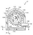
도 11은 부분적인 단면도를 도시하는 상기 수전력 발전 시스템(12)의 또 다른 실시 예이다. 이전의 실시 예와 유사하게, 상기 수전력 발전 시스템(12)은 수처리 시스템(10)에서 이용될 수 있다. 또한 상기 수전력 발전 시스템(12)은 가압된 유체를 가지는 임의의 다른 형태의 시스템에 포함될 수 있다. 상기 수전력 발전 시스템(12)은 또한 UV 소스, 필터, 전자기술 등과 같은 수처리 시스템의 특징을 포함할 수 있다.11 is yet another embodiment of the hydro-
상기 도시된 수전력 발전 시스템(12)은 제거된 측부 커버와 함께 도시되는 외부 하우징(1102)을 포함한다. 또한 상기 수전력 발전 시스템(12)은 내측 하우징(1104), 중심 막대(1106) 및 노즐(1108)을 포함한다. 상기 외부 하우징(1102)은 플라스틱, 금속, 탄소 섬유 또는 다른 단단한 물질이 될 수 있고, 공동(1110)을 포함한다. 상기 공동(1110)은 상기 외측 하우징(1102)의 내부 표면(1112)과 접촉하지 않는 상기 내측 하우징(1104)을 수용할 수 있는 사이즈의 공기층(airspace)이다. 또한 출구(1114)가 상기 외측 하우징(1102)에 포함된다. 상기 출구(1114)는 가동 중에 상기 공기층을 유지하는 상기 공동(1110)으로부터의 중력에 의해 상기 외측 하우징(1102)에 존재하는 유체가 빠져나가도록 하는 어퍼쳐(aperture)가 될 수 있다.The illustrated hydroelectric
상기 내측 하우징(1104)은 일반적으로 원통형의 플라스틱, 금속, 탄소 섬유 또는 다른 유사한 물질이 될 수 있다. 상기 내측 하우징(1104)은 상기 외측 하우징(1102)의 공동(1110) 내에 있는 상기 중심 막대(1106)의 한 부분 이상을 둘러싸는 외부 하우징(1102)에 장착될 수 있다. 상기 중심 막대(1106)는 상기 외측 하우징(1102)과 함께 단단하게 결합될 수 있고, 내측 하우징(1104)으로 확장될 수 있다. 상기 중심 막대(1106)는 스테인리스 스틸 같은 임의의 단단하고, 종축으로 확장하는 물질이 될 수 있다.The
다수의 부시(bushings)(1116)는 상기 내측 하우징(1104)과 결합될 수 있고, 상기 중심 막대(1106)를 둘러싼다. 각각의 부시(1116)는 플라스틱, 금속 또는 다른 유사한 물질로 형성되는 슬리브(sleeve)가 될 수 있다. 상기 부시(1116)는 상기 중심 막대(1106)를 수용하는 어퍼쳐와 함께 형성될 수 있고, 외측 표면은 상기 내측 하우징(1104)의 외측 표면에 있는 어퍼쳐 내에 끼워지도록 형성될 수 있다. 상기 부시(1116)의 어퍼쳐는 상기 부시(1116)가 상기 중심 막대(1106)에 접촉하지 않고 상기 외측 하우징(1102) 내의 상기 중심 막대(1106) 둘레를 회전할 수 있도록 충분히 클 수 있다. 상기 부시(1116)의 외측 표면은 상기 내측 하우징(1104) 및 상기 부시(1116)가 함께 회전하도록 상기 내측 하우징(1104)의 외측 표면에 단단하게 결합될 수 있다. 택일적으로, 상기 부시(1116) 및 상기 내측 하우징(1104)은 상기 중심 막대(1106) 주위를 독립적으로 회전할 수 있다.A number of
상기 내측 하우징(1104)은 또한 단단하게 결합되고, 상기 내측 하우징(1104)의 외측 표면(1120)으로부터 외부로 확장하는 다수의 패들을 포함할 수 있다. 상기 패들(1118)은 플라스틱, 탄소 섬유, 금속 또는 다른 유사한 물질로 형성될 수 있 다. 상기 내측 하우징(1104)이 회전함에 띠라, 각각의 상기 패들(1118)이 몇몇 지점에서 상기 노즐(1108)에 인접하여 위치하도록 상기 패들(1118)은 상기 내측 하우징(1104)의 외측 표면(1120)에 수직으로 위치될 수 있다.The
상기 노즐(1108)은 도시된 것처럼 상기 내측 하우징(1104) 및 상기 출구(1114) 사이의 공동(1110)으로 확장하도록 장착될 수 있다. 앞의 도 1-5에서 설명된 노즐(14)과 유사하게, 상기 노즐(1108)은 가압된 유체의 속도를 증가시킨다. 제1 속도로 노즐 입구(1122)에 제공되는 가압된 유체는 상기 노즐(1108)을 통해 흐르고, 상기 제1 속도보다 실질적으로 더 높은 제2 속도로 노즐 출구(1124)로부터 방출된다. 상기 노즐(1108)을 가진 상기 공동으로 방출된 유체는 상기 패들(1118)에서의 공기층을 통하도록 향하게 된다.The
도 12는 상기 노즐 입구(1122)(도 11)로부터 바라보는 상기 노즐(1108)의 단부도이다. 상기 노즐(1108)은 상기 노즐 출구(1124)(도 11)를 향하면서 직경이 감소되는 축 내경(axial bore)이 되는 통로(1202)를 포함한다. 립(rib)(1204)이 상기 통로(1202)에 포함된다. 상기 립(1204)은 상기 노즐(1108)의 내측 표면(1206)과 결합되고, 상기 내측 표면(1206)으로부터 상기 노즐(1108)의 중심 축(1208)을 향하여 밖으로 연장된다.12 is an end view of the
도 13은 상기 립(1204)을 포함하는 도 12에 도시된 상기 노즐(1108)의 잘라낸 하부도(bottom view)이다. 상기 노즐(1108)을 통한 상기 통로(1202)는 제1 직선 섹션(1302)이 뒤따라오는 상기 노즐 입구(1122)에 인접한 제1 각 섹션(1302), 제2 각 섹션(1308) 및 노즐 출구(1124)를 형성하는 제2 직선 섹션(1310)을 포함한다. 상기 통로(1202)는 상기 노즐 입구(1122)에서 약 10.8 밀리미터 정도의 사전에 결정된 입구 직경이 될 수 있다. 상기 제1 각 섹션(1302) 내에서, 상기 통로(1202)의 직경은 상기 중심 축(1208)에 대하여 약 20도 정도의 사전에 결정된 각에서 상기 노즐 출구(1124)를 향하여 직경이 균일하게 감소될 수 있다. 상기 제2 직선 섹션(1310)은 약 1.85 밀리미터의 사전에 결정된 제2 노즐 직경으로 상기 통로(1202)를 유지함으로써 상기 노즐 출구(1124)를 형성할 수 있다.FIG. 13 is a cutaway bottom view of the
상기 제1 및 제2 노즐 직경은 상기 노즐(1108)에 제공된 유압의 가용 범위를 바탕으로 하여 결정될 수 있다. 한 예에서, 상기 제1 직선 섹션(1304)의 직경은 상대적으로 변하지 않은 채 유지될 수 있고, 상기 제2 직선 섹션(1310)의 직경은 상기 노즐(1108)에 도입되는 유체의 압력을 바탕으로 하여 변할 수 있다. 예를 들면, 상기 제1 직선 섹션(1304)의 직경은 약 5.8 밀리미터로 유지될 수 있고, 상기 제2 직선 섹션(1310)은 약 1.9 밀리미터 또는 그보다 작도록 형성될 수 있다. 따라서 상기 노즐(1108)의 상기 제2 직선 섹션(1310)의 직경은 상기 노즐(1108)의 상기 제1 직선 섹션(1304) 직경의 약 33% 또는 이하가 된다.The first and second nozzle diameters may be determined based on the available range of hydraulic pressure provided to the
또 다른 예에서, 상기 제2 직선 섹션(1310)은 약 34 kPa 및 850 kPa 사이(약 5 및 125 PSI 사이)로 상기 노즐 입구(1122)에 가압된 유체를 이용하기 위해 약 0.8 밀리미터 및 약 1.9밀리미터 사이(약 0.03 및 0.075인치 사이)의 범위에서 형성될 수 있다. 이 예에서, 상기 노즐(1108)은 상기 노즐(1108)의 제1 직선 섹션(1304) 직경의 약 14% 및 33% 사이가 될 수 있다. 이 예에서 상기 노즐(1108)을 통한 결과적인 흐름율은 34 kPa에서 약 0.44 리터/분으로부터 850 kPa에서 약 4.16 리터/분까지(약 0.115 겔론/분에서 약 1.1 겔론/분까지) 범위가 될 수 있다.In another example, the second
상기 립(1204)은 상기 통로(1102)를 통해 흐르는 상기 유체의 소용돌이 및 다른 비-라미나 행동을 최소화하는 임의의 배열이 될 수 있다. 상기 도시된 립(1204)은 상기 노즐 입구(1122)에서 시작하고, 상기 중심축(1208)을 따라 상기 제1 각 섹션(1302), 상기 제1 직선 섹션(1304)을 통해, 상기 가늘어지는 섹션(tapered section)(1306)으로 사전에 결정된 거리만큼 연장된다. 비록 균일한 폭을 가지는 것으로 도시되었지만, 다른 예에서, 상기 립(1204)은 하나 이상의 가늘어지는 폭 섹션, 벌브(bulbs), 곡면 또는 상기 노즐(1108)을 통해 상기 유체의 라미나 흐름을 촉진하는 임의의 다른 배열을 포함할 수 있다. 또한 상기 립(1204)의 길이는 상기 통로(1202)를 통해 흐르는 유체의 소용돌이를 최상으로 제거하도록 도시된 것보다 더 길거나 또는 더 짧을 수 있다.The
도 14는 도 12에서 도시되는 상기 립(1204)을 포함하는 노즐(1108)의 잘려진 측면도이다. 상기 예의 립(1204)은 상기 통로(1202)의 노즐 입구(1122)에서 사전에 결정된 거리만큼 상기 중심 축(1208)을 향하여 상기 내부 표면(1206)으로부터 밖으로 연장된다. 상기 립(1204)이 상기 중심 축(1208)을 따라 상기 노즐 출구(1124)를 향하여 연장됨에 따라 상기 립(1204)이 상기 내부 표면(1206)으로부터 연장되는 거리는 점진적으로 제로(zero)로 감소된다. 상기 도시된 예에서, 상기 립(1204)이 상기 중심 축(1208)을 따라 상기 노즐 출구(1124)를 향해 연장됨에 따라 상기 립(1204)은 상기 중심 축(1208)으로부터 더 멀어지는 거리까지 확장되도록 가늘어진다. 또한 상기 내부 표면(1206) 및 상기 중심 축(1208) 사이의 거리는, 상기 립(1204)을 더 가늘어지게 하며, 상기 노즐 출구(1124)로 향하면서 더 작아진다. 다른 예에서, 상기 립(1204)은 소용돌이 효과를 줄이는 임의의 다른 형상을 형성할 수 있고, 상기 노즐(1108)을 통해 상기 유체의 라미나 흐름을 촉진시킬 수 있다.FIG. 14 is a cutaway side view of the
도 11을 다시 참조하면, 동작 중에, 상기 노즐(1108)을 통해 흐르는 유체는 상기 유체의 속도가 상기 노즐(1108) 내에서 가속되는 동안 라미나 흐름을 유지할 수 있다. 상기 유체는 고속의 흐름으로 상기 노즐(1108)로부터 방출될 수 있다. 실질적으로 라미나 흐름 때문에, 유체의 흐름은 방출 후에 상기 노즐 출구(1124)와 같은 직경의 잘 규정된 흐름으로 남을 수 있다. 그러므로 유체의 흐름에 의해 생산되는 유체 스프레이는 최소화되고, 상기 흐르는 유체의 운동 에너지는 상대적으로 작은 영역에 집중될 수 있다.Referring back to FIG. 11, during operation, fluid flowing through the
상기 유체의 흐름은 상기 패들(1118)을 향하도록 될 수 있다. 상기 패들(1118)에 부딪칠 때, 상기 유체에 존재하는 운동에너지는 상기 내측 하우징(1104)의 회전 에너지로 효과적으로 전송될 수 있다. 상기 내측 하우징(1104)이 회전함에 따라, 각각의 상기 패들(1118)은 상기 노즐(1108)로부터 방출되는 고속 유체 흐름으로 들어가고, 상기 흐르는 유체의 흐름에 존재하는 모든 운동에너지를 실질적으로 수용한다.The flow of fluid may be directed towards the
일단 상기 운동 에너지가 상기 유체로부터 추출되면, 상기 유체는 중력에 의해 상기 출구(1114)로 떨어지고, 상기 외측 하우징(1102) 밖으로 도관을 통해 흐른다. 상기 도관을 통한 흐름 때문에, 상기 외측 하우징(1102)은 실질적으로 유체가 없는 상태로 남는다. 비록 몇몇 유체가 상기 노즐(1108)로부터 방출되는 유체의 일 정한 흐름 때문에 존재할지라도, 상기 도관을 통한 흐름은 상기 노즐(1108) 및 상기 내측 하우징(1104)이 상기 유체에 잠기지 않도록 충분히 낮게 상기 외측 하우징(1102)의 유체 레벨을 유지할 수 있다. 따라서 상기 노즐(1108) 및 상기 내측 하우징(1104)은 최소의 유체 임피던스 손실을 가지고 상기 외측 하우징(1102) 내의 공기층에서 동작한다.Once the kinetic energy is extracted from the fluid, the fluid falls by gravity to the
몇몇 상기 유체는 상기 패들(1118) 상에 일시적으로 유지할 수 있고, 상기 내측 하우징(1104)의 회전력에 의해 상기 외측 하우징(1102)의 내측 표면(1112)으로 던져질 수 있다. 또한 몇몇 상기 유체는 상기 패들(1118)에 충돌할 수 있고, 상기 내측 표면(1112)으로 굴절될 수 있다.Some of the fluid may be temporarily held on the
상기 내측 표면(1112)은 상기 공동(1110) 내에 유체 스프레이를 최소로 하기 위해 덕팅(ducting)과 함께 형성될 수 있다. 상기 공동(1110)내 유체 스프레이의 최소화는 초과 유체를 상기 회전하는 내측 하우징(1104)으로부터 떨어지도록 유지함으로써 상기 회전하는 내측 하우징(1104)의 유체 임피던스 손실을 최소화 한다.The
상기 내측 표면(1112)에 포함되는 상기 덕팅은 또한 상기 유체 스프레이를 효과적으로 수집하고, 상기 유체를 상기 출구(1114)로 흐르게 하도록 디자인된 소용돌이 패턴을 가지도록 형성될 수 있다. 따라서 상기 공동(1110)은 실질적으로 유체가 빈 상태로 유지되고, 상기 노즐(108)의 상기 노즐 출구(1124)가 상기 유체에 잠기지 않도록 작동 중에 공기(또는 몇몇 다른 기체)로 채워진다.The ducting included in the
도 15는 도 11의 상기 외측 하우징(1102)의 단면도 내의 내측 표면(1112)의 한 예를 도시한다. 상기 내측 표면(1112)은 상기 내측 표면(1112)으로부터 상기 내 측 하우징(1104)(도 11)을 향하여 밖으로 연장되는, 다수의 핑거(fingers)(1502) 형태의 덕팅을 포함한다. 각각의 상기 핑거(1502)는 개개의 피라미드 형상의 부재(members)로서 형성될 수 있다. 다른 예에서, 상기 핑거(1502)는 그루브(grooves), 링(rings), 버팀목, 트랙(tracks) 또는 상기 외측 하우징(1102)의 내측 표면(1112)에 있는 임의의 다른 형태의 불규칙이 될 수 있다. 상기 핑거(1502)는 결정된 패턴에 위치될 수 있다. 상기 패턴은 상기 출구(1114)(도 11)로 상기 유체의 도관을 따른 흐름을 최대화하고, 상기 유체 스프레이를 최소하도록 상기 패들(1118) 및 상기 회전하는 내측 하우징(1104)으로부터 던져지는 상기 유체의 분석 또는 모델링에 바탕을 둔 회전 패턴이 될 수 있다.FIG. 15 shows an example of an
상기 핑거(1502)는 상기 외측 하우징(1102)의 내부 표면(1112)에 접촉하는 상기 유체의 유체 스프레이를 최소로 할 수 있다. 또한 상기 핑거(1502)는 상기 외측 하우징(1102)에 포함되는 외측 도관(1506) 및 중심 도관(1504)으로 물을 흐르게 하도록 배열될 수 있다. 상기 중심 도관(1504) 및 외측 도관(1506)은 상기 출구(1114)(도 11)를 향해 상기 유체를 도관으로 흐르게 하는 v-형상의 그루브 또는 몇몇 다른 형상의 도관이 될 수 있다. 상기 내부 표면(1112)은 또한 다수의 가지 채널(1508)을 포함할 수 있다. 상기 가지 도관(1508)은 상기 외측 도관(1506) 또는 상기 중심 도관(1504)에 상기 유체를 흐르게 하는 내부 표면(1112)에서의 활모양 경로가 될 수 있다. 상기 채널은 또한 상기 출구(1114)(도 11)로 상기 유체의 도관을 통한 흐름을 최대화하고, 상기 유체 스프레이를 최소화하기위해 상기 회전하는 내측 하우징(1104)으로부터 던져진 상기 유체를 분석하는 것 또는 모델링을 바탕으 로 하는 소용돌이 패턴에 위치될 수 있다.The
상기 핑거(1502)는 각각의 상기 가지 도관(1508)을 따라 위치될 수 있다. 상기 핑거(1502)에 부딪치는 유체는 상기 핑거(1502)에 의해 “포획(captured)"될 수 있다. 상기 유체는 상기 핑거(1502)를 지나 상기 가지 도관(1508)으로 흐르고, 그 다음에 상기 중심 도관 도는 상기 외측 도관(1506)으로 흐른다.The
도 16은 도시 목적으로 중심 막대(1106) 및 상기 내측 하우징(1104)을 제거한 도 11에 도시된 상기 외측 하우징(1102)의 측면도이다. 상기 외측 하우징(1102)의 내부 표면(1112)은 상기 내부 표면(1112) 내에 유체에 대한 활모양의 경로를 형성하는 다수의 가지 도관(1602)을 따라 놓여지는 상기 핑거(1502)를 포함한다. 상기 핑거(1502)에 의해 “포획”되는 유체는 상기 핑거(1502)를 지나 상기 가지 도관(1602)으로 흐르고, 상기 외측 도관(1506)(도 14) 및/또는 상기 출구(1114)로 도관을 통해 흐른다.FIG. 16 is a side view of the
도 17은 상기 출구(1114)를 포함하는 도 11에 도시된 상기 외측 하우징(1102)의 하부의 단면도이다. 도 11에서 도시되는 상기 외측 하우징(1102)의 하부는 유사하게 상기 출구(1114)로 상기 유체를 향하게 하는 활모양의 통로가 되는 다수의 가지 도관을 포함한다. 상기 핑거(1502)는 각각의 상기 가지 채널(1702)을 따라 놓여질 수 있다.FIG. 17 is a cross-sectional view of the bottom of the
도 18은 상기 중심 막대(1106)를 포함하는 도 11에서 도시된 상기 내측 하우징(1104)의 분해된 사시도이다. 상기 부시(1116), 상기 패들(118), 제1 허브(1802), 제2 허브(1804), 회전자(1806) 및 고정자(1808)도 상기 내측 하우징에 포함된다. 상기 중심 막대(1106)는 상기 내측 하우징(1104)을 통해 중심 축(1812)을 따라 연장되고, 상기 고정자(1808)에 대한 중심을 정하는 기능(entering function)을 제공하기 위해 상기 부시(116)와 함께 협력적으로 동작한다. 상기 부시(1116)는 각각의 상기 제1 및 제2 허브(1802 및 1804)의 제1 단부에 형성되는 부시 어퍼쳐(1816) 내에 축 방향으로 끼워지도록 형성될 수 있다.18 is an exploded perspective view of the
상기 제1 및 제2 허브(1802 및 1804)는 플라스틱, 탄소섬유 또는 임의의 다른 단단한 물질로 형성될 수 있다. 각각의 상기 제1 및 제2 허브(1802 및 1804)는 일반적으로 원통형이고, 개방 단부(open end)(1818)를 가지는 공동을 형성할 수 있다. 상기 개방 단부(1818)는 상기 부시 어퍼쳐(1816)를 포함하는 상기 제1 단부 맞은편의 제2 단부에 있을 수 있다. 상기 제1 및 제2 허브(1802 및 1804)는 상기 내측 하우징(1104)의 상기 외측 표면(1120)(도 11)을 형성도록 상기 개방 단부에서 함께 결함될 수 있다.The first and
각각의 상기 제1 및 제2 허브(1802 및 1804)는 보유 링(retaining ring)(1820)을 포함한다. 상기 보유 링(1820)은 상기 중심 축(1812)과 평행하게 상기 개방 단부(1818)의 변부 주위에서 밖으로 연장하는 다수의 러그(lugs)를 포함한다. 다수의 홈(slot)은 상기 보유 링(1820)에 있는 각각의 상기 러그(1822) 사이에서 형성될 수 있다. 상기 러그(1822)는 상기 제1 및 제2 허브(1802 및 1804)가 상기 개방 단부(1818)에서 결합될 때 서로 인접하여 접촉하도록 정렬될 수 있다. 그러므로 상기 홈(1824)은 또한 어펴쳐를 형성하기 위해 상기 제1 및 제2 허브(1802 및 1804) 사이에서 정렬될 수 있다.Each of the first and
상기 제1 및 제2 허브(1802 및 1804)는 또한 상기 내측 하우징(1104)의 외측 표면 주위에서 중심을 공유하며 연속적으로 배열되는 다수의 배출구(vents)(1826)를 포함한다. 상기 배출구(1826)는 상기 내측 하우징(1104) 내부의 공동 및 상기 내측 하우징의 외부 측부 사이에 유체 통신을 가능하게 하는 어펴쳐를 형성한다. 따라서 유체는 상기 배출구(1826)를 통해서 상기 내측 하우징(1104)으로 들어가거나 또는 탈출할 수 있다.The first and
상기 내측 하우징(1104)이 회전할 때, 상기 내측 하우징(1104) 내의 유체는 생성되는 상기 회전에 의한 원심력에 의해 상기 배출구(1826)을 통해 밖으로 흐른다. 그러므로 상기 내측 하우징(1104)이 고 RPM에서 회전할 때, 상기 내측 하우징(1104) 내의 유체에 의한 유체 임피던스 손실은 상기 배출구(1826)를 통해 진행되는 유체의 배출에 의해 최소화된다. 상기 회전하는 내측 하우징(1104)은 그러므로 실질적으로 유체가 빈 상태의 공동을 유지할 수 있다. 상기 공동은 실질적으로 건조한 상태가 될 수 있고, 공기(또는 몇몇 다른 기체)로 채워질 수 있다. 비록 상기 공동이 젖을 수 있지만, 상기 공동은 효과적인 동작에 영향을 주는 충분한 양의 유체가 없는 상태로 유지될 수 있다. 상기 배출구(1826)는 또한 상기 내측 하우징(1104)을 통해 냉각을 위한 공기 흐름을 제공할 수 있다.When the
상기 제1 및 제2 허브(1802 및 1804) 각각에서 형성되는 상기 공동 내에 상기 제1 및 제2 허브(1802 및 1804)로부터 상기 중심 축(1812)을 향해 밖으로 연장되는 다수의 키퍼(keepers)(1828)가 있다. 상기 키퍼(1828)는 상기 키퍼 사이에 다수의 노치(notch)를 형성하도록 결정된 거리만큼 떨어져 위치될 수 있다. 상기 키 퍼(1828)는 상기 제1 및 제2 허부(1802 및 1804)의 필수적인 부분으로서 형성될 수 있다. 택일적으로, 상기 키퍼(1828)는 플라스틱, 금속, 탄소 섬유 또는 상기 개개의 공동 내에서 각각의 상기 제1 및 제2 허부(1802 및 1804)의 내부 표면과 결합할 수 있는 임의의 다른 단단한 물질로 개별적으로 형성될 수 있다.A number of keepers extending out from the first and
상기 회전자(1806)는 키퍼 링(1834) 및 자석(1836)을 포함할 수 있다. 상기 키퍼 링(1834)은 철 또는 다른 유사한 철을 함유한(또는 철을 함유하지 않은) 물질로 형성되는 원통형의 슬리브가 될 수 있다. 상기 제1 및 제2 허브(1802 및 1804)가 함께 결합될 때, 상기 키퍼 링(1834)의 부분은 각각의 상기 제1 및 제2 허브(1802 및 1804)의 공동에 위치될 수 있다. 상기 키퍼 링(1834)은 상기 키퍼 링(1834)이 상기 내측 하우징(1104)과 함께 회전하도록 각각의 상기 제1 및 제2 허부(1802 및 1804) 내의 키퍼(1828)와 결합할 수 있다. 상기 키퍼 링(1834)은 발전기 효율을 향상하기 위해 상기 자석(1836)과 함께 동작하는 플럭스 집중 장치로서 배열될 수 있다.The
상기 자석(1836)은 상기 키퍼 링(1834)과 결합될 수 있고, 또한 상기 내측 하우징(1104)과 함께 회전한다. 상기 자석(1836)은 소결된 또는 결합된(bonded) 네오디뮴(neodymium) 철 보론(NdFeB) 희토류 자석(rare earth magnet) 같은, 영구 자석이 될 수 있다. 상기 자석(1836)은 상기 구조를 따라 배열된 요구되는 수의 북극 및 남극을 가지는 연속된 단일 구조로서 형성될 수 있다. 택일적으로, 다수의 개개 자석은 정렬되고, 상기 키퍼 링(1834)과 결합될 수 있다.The
상기 발전기의 백 EMF는 상기 자석(1836)을 상기 키퍼(1828)와 직접 결합함 으로서 유리하게 감소될 수 있다. 그러므로 상기 키퍼 링(1834)은 제거될 수 있다. 앞에서 설명한 것처럼, 상기 백 EMF의 감소는 보다 빠른 가속을 가능하게 하고, 그것은 UV 소스의 “일시적인(instant on)" 능력을 제공하는 것처럼, 몇몇 부하와 함께 장점이 될 수 있다.The back EMF of the generator can be advantageously reduced by directly coupling the
상기 고정자(1808)는 앞에서 설명한 것처럼, 하나 이상의 고정 권선(도시되지 않음)으로 둘러싸인 다수의 극(1840)으로 형성된다. 상기 극(1840)은 장착 플레이트(1842)와 결합된 금속 박층이 될 수 있다. 상기 장착 플레이트(1842)는 금속, 플라스틱 또는 임의의 다른 단단한 물질이 될 수 있고, 상기 중심 막대(1106)와 결합될 수 있다. 상기 고정자(1808)는 상기 제1 및 제2 허부(1802 및 1804)에 의해 형성되는 공동에 위치될 수 있고, 이때, 상기 자석(1836)은 사이에 공기 갭을 가지는 상기 극(1840)에 인접한 상기 고정자(1808) 주위에 위치된다.The
상기 권선이 상기 권선을 형성하기 위해 이용되는 도선 상의 에나멜 코팅과 같은, 비-도체 물질로 밀봉될 수 있기 때문에 상기 고정자(1808)는 축축한 상태로 또는 건조한 상태로 동작될 수 있다. 택일적으로 상기 권선은 플라스틱, 고무 또는 몇몇 다른 방수 물질로 오버-몰드(over-molded)될 수 있다. 물 저항(water resistance)을 제공하는 것 외에, 그와 같은 오버-몰딩은 또한 상기 내측 하우징(1104)이 상기 고정자(1808) 주위를 고속으로 회전할 때 유체 임피던스 손실에 기여하는 상기 고정자(1808)의 다른 특징부 및 변부를 줄일 수 있다.The
상기 회전자(1806) 및 고정자(1808)의 결합은 3차원 전력을 발생하는 발전기를 형성할 수 있다. 택일적으로, 상기 발전기는 단일 위상 전력을 발생할 수 있다. 상기 발전기에 의해 발생된 전력은 전력 공급 장치 라인(power supply line)(1844) 에 제공될 수 있다. 상기 전력 공급 장치 라인(1844)은 상기 고정자(1808)의 권선에 전기적으로 연결될 수 있다. 상기 전력 공급 장치 라인(1844)은 상기 중심 막대(1106)를 통해 상기 중심 축(1812)을 따라 연장되는 통로를 지나 보내질 수 있다. 전력 이외에, 상기 회전자의 회전 및/또는 생산되는 상기 전력은 흐름을 바탕으로 하는 측정을 수행하기 위해 감시될 수 있다.The combination of the
상기 고정자(1808) 및 상기 자석(1836) 사이의 공기 갭은 상기 주위 부시(1116) 및 상기 중심 막대(1106)와 결합된 상기 자석(1836)의 자기장에 의해 유지될 수 있다. 상기 고정자(1808)는 상기 중심 막대(1106)와 결합될 수 있다. 따라서 상기 내측 하우징(1104)의 회전 및 그로인한 상기 회전자의 회전에 따라, 상기 회전하는 자기장은 상기 고정자(18080의 권선에 전력의 생산을 유도한다.An air gap between the
동작 중에, 상기 내측 하우징(1104)은 유체의 단일한 고속 흐름에 의해, 5000 RPM 이상의 상대적으로 높은 분당회전수(RPM)에서 회전할 수 있다. 상기 상대적으로 높은 RPM은 상대적으로 작은 사이즈의 상기 내측 하우징(1104)에 의해 달성될 수 있고, 유체 임피던스 손실을 최소로 할 수 있다. 상기 일반적으로 원통형인 내측 하우징(1104)의 직경은 약 40 밀리미터보다 작게 즉, 약 40밀리미터에서 약 10밀리미터의 범위에서 이루어질 수 있다. 상기 노즐(1108)(도 11)의 상기 노즐 출구(1124)(도 11)의 직경은 약 1.9 밀리미터에서 약 0.8밀리미터의 범위가 될 수 있으므로, 상기 노즐출구(1124)의 직경은 상기 하우징(1104) 직경의 약 4.75% 및 약 8% 사이에 있다.In operation, the
상기 내측 하우징(1104)의 회전 스피드 및, 그로인한 상기 발전기에 의해 생산되는 전력의 양은 상기 내측 하우징(1104)의 직경 및 상기 노즐(1108)(도 11)에 의해 방출되는 상기 유체의 속도에 바탕을 둘 수 있다. 그러므로 유압 및 흐름율의 범위 내에서 상기 내측 하우징(1104) 직경 범위 및 상기 노즐(1108)(도 11)의 노즐 출구(1124)(도 11)의 직경 범위에 대하여, 전력의 범위가 출력(output)될 수 있다. 예를 들면, 약 0.8 밀리미터 및 약 1.9 밀리미터 사이에 해당하는 상기 노즐(1108)의 노즐 출구(1124)의 직경 범위는 약 0.44리터/분 및 약 4.16리터/분(약 0.115 겔론/분 및 약 1.1 겔론/분) 사이를 배출할 수 있다. 상기 흐름율은 약 34 kPa 및 약 413 kPa(약 5 lb/sq.in 및 약 60 lb/sq.in) 사이에 해당하는 상기 노즐 입구(1122)(도 11)에서의 압력 범위에 바탕을 두고 있다. 상기 내측 하우징(1104)의 결과적인 회전은 약 0.15 와트 및 약 30 와트 사이의 전력을 생산할 수 있다. 이 예시적인 범위에서 상기 발전기로부터의 전력은 UV 램프 또는 전자 조립체를 직접 가동할 수 있고, 커패시터, 슈퍼 커패시터, 초(ultra) 커패시터 및/또는 배터리같은 에너지 저장 디바이스를 충전하도록 정류될 수 있다.The rotational speed of the
상기 자석(1836)은 또한 상기 내측 하우징(1104)의 정렬 및 균형(balancing)을 제공할 수 있다. 상기 자석(1836)의 무게는 효율을 증가하기 위해 상기 내측 하우징(1104)의 회전이 균형을 유지하며 회전(spin balance)하도록 배열될 수 있다. 그러므로 상기 내측 하우징(1104)은 진동 또는 균형이 깨진 회전과 관련된 다른 효과를 최소화하며, 고 RPM에서 부드럽게 회전할 수 있다. 앞에서 설명하였듯이, 고 RPM에서 효율적인 전력 생산 때문에 상기 자석(1836)의 무게는 또한 최소로 될 수 있다.The
또한 상기 자석(1836)의 자기장은 상기 회전자(1806)의 정렬을 유지할 수 있고, 그 결과 상기 고정자(1808)를 가지는 내측 하우징(1104)의 정렬도 유지할 수 있다. 상기 자석(1836)의 실질적으로 같게 분포된 자기장은 축 방향으로 상기 고정자(1808) 및 회전자(1806)를 정렬시킬 수 있다. 따라서 상기 내측 하우징(1104)은 또한 상기 중심 막대(1106)와 함께 축 방향으로 정렬될 수 있다. 상기 부시(1116) 및 상기 중심 막대(1106)는 상기 내측 하우징(1104)을 축 방향으로 정렬하는데 도움을 줄 수 있으나, 상기 내측 하우징(1104)은 상기 자석(1836)의 자기장에 의해 상기 중심 막대(1106)와 축 방향 정렬로 매달리게 될 수 있다. 그러므로 상기 주위의 회전하는 부시(1116) 및 회전하지 않는 중심 막대(1106)사이의 마찰 손실은 최소화 된다. 또한 상기 수전력 발전기(12)가 스테이(stays), 걸쇠(latches) 또는 상대적인 위치를 유지하게 하는 임의의 다른 메커니즘 없이 수직, 수평 등으로 장착될 때, 상기 자기장은 상기 고정자(1808)를 포함하는 상기 내측 하우징(1104)의 위치 관계를 유지할 수 있다.In addition, the magnetic field of the
도 11 및 18에서 도시된 것처럼, 상기 패들(1118)은 상기 내측 하우징(1104)을 중심을 공유하며 둘러싸는 링을 형성할 수 있다. 상기 패들(1118)은 상기 내측 하우징(1104)의 외측 표면에 결합된 개별적으로 생산된 부분이 될 수 있다. 각각의 상기 패들(1118)은 상기 제1 및 제2 허브(1802 및 1804)가 함께 결합될 때, 상기 링을 형성하는 상기 노치(1824) 중의 하나에 위치를 유지할 수 있다. 택일적으로 상기 패들(1118)은 아교, 용접, 마찰 핏 또는 임의의 다른 메커니즘에 의해 상기 제1 및/또는 제2 허브(1802 및 1804)에 그룹으로서 결합되거나 또는 개별적으로 결합될 수 있다.As shown in FIGS. 11 and 18, the
상기 패들(1118)은 비용을 줄이고 생산성을 향상하기 위해 개별적으로 생산되고, 그 다음에 링에 결합될 수 있다. 또한 상기 개개의 패들(1118)의 기하구조에 실질적인 변화를 주지 않고, 상기 내측 하우징(1104)의 직경 및 상기 패들(1118) 링의 직경은 변할 수 있다. 상기 개개 패들(1118)의 배열뿐만 아니라 상기 제1 및 제2 허브(1802 및 1804) 내의 상기 보유 링(retainer ring)(1820)은 상기 노치(1824) 내에 상기 패들(1118)의 위치를 유지하도록 협력적으로 동작할 수 있다.The
도 19는 도 18에서 도시되는 상기 패들(1118)의 한 예에 대한 사시도이다. 상기 도시된 패들(1118)은 일반적으로 오목하고, 베이스(base)(1902), 제1 패들 섹션(1904), 제2 패들 섹션(1906) 및 홈(1908)을 포함할 수 있다. 상기 베이스(1902)는 상기 제1 및 제2 허브(1802 및 1804)(도 18)의 인접한 홈(1824)(도 18)내에 끼워지도록 형성될 수 있다. 상기 베이스(1902)는 더 낮은 표면(1912) 및 발(foot)(1914)을 포함할 수 있다. 상기 더 낮은 표면(1912)은 상기 제1 및 제2 허브(1802 및 1804)(도 18)의 내부 표면의 곡면 반지름과 유사한, 사전에 결정된 곡면 반지름을 가지면서 굽어질 수 있다. 상기 발(1914)은 일반적으로 삼각형 형상이 될 수 있고, 제1 각 표면(1916), 제2 각 표면(1918) 및 앞쪽 표면(face surface)(1920)을 포함할 수 있다.19 is a perspective view of one example of the
도 18 및 19를 참조하면, 상기 패들(1118)이 상기 내측 하우징(1104)에 장착될 때, 상기 베이스(1902)는 각각의 상기 제1 및 제2 허부(1802 및 1804)에 인접하 게 위치한 노치(1824)에 배열될 수 있다. 각각의 패들(1118)의 상기 발(1914)은 상기 제1 및 제2 허브(1802 및 1804) 상의 상기 러그(1822)에 의해 상기 노치(1824)에 고정될 수 있다. 상기 도시된 예에서, 상기 제1 및 제2 각 표면(1916 및 1918)은 각각의 상기 제1 및 제2 허브(1802 및 1804) 상의 상기 러그(1822) 중 하나에 각각 인접하여 접촉할 수 있다.18 and 19, when the
도 20은 상기 제1 및 제2 패들 섹션(1904 및 1906) 그리고 상기 발(1914)을 도시하는 도 19의 상기 패들(1118)에 대한 위에서 본 단면도이다. 상기 패들(1118)의 뒤쪽 표면(2002) 또한 도시되었다. 상기 패들(1118)이 상기 내측 하우징(1104)(도 11)에 장착될 때, 상기 뒤쪽 표면(2002)은 인접하여 장착된 패들(1118)의 상기 발(1914)의 앞쪽 표면(1920)(도 19)에 인접하여 접촉할 수 있다. 그러므로 상기 패들(1118)의 상기 베이스(1902)(도 19)는 패들(1118)의 상기 링에 인접하여 위치한 상기 패들(1118) 및 상기 러그(1822)(도 18)의 조합에 의해 효율적으로 고정될 수 있다. 각각의 상기 패들(1118)의 상기 베이스(1902)는 상기 내측 하우징(1104)의 외측 표면에 인접한 부서지지 않은 중심을 공유하는 링의 부분을 형성할 수 있다. 상기 패들(1118)은 마찰 핏, 아교, 용접 또는 임의의 다른 결합 메커니즘 또는 물질에 의해 고정될 수 있다.FIG. 20 is a cross-sectional view from above of the
도 19를 다시 참조하면, 상기 제1 및 제2 패들 섹션(1904 및 1906)은 각각 유체의 고속 흐름을 수용할 수 있는 분리된 오목부분(depression) 또는 컵을 제공할 수 있다. 도 20에서 잘 도시되는 것처럼, 각각의 상기 제1 및 제2 패들 섹션(1904 및 1906)은 상기 패들 섹션(1904 및 1906)에 부딪치는 유체의 흐름을 최적 화하기 위해 타원형이 될 수 있다. 상기 내측 하우징(1104)(도 11)이 고 RPM에서 회전함에 따라, 상기 홈(1918)은 상기 유체의 흐름이 각각의 상기 패들(1118)에 효율적으로 부딪치도록 한다.Referring again to FIG. 19, the first and
앞에서 설명된 상기 수전력 발전 시스템(12)은 또한 수처리 발전 시스템의 능력을 포함할 수 있다. 한 예에서, 상기 수전력 발전 시스템은 수도꼭지(faucet) 또는 다른 배관 고정장치에 장착될 수 있다. 수전력 발전 시스템(12)이 장착된 상기 수도꼭지의 입구는 상기 수도꼭지의 물 출구인 단부에 결합될 수 있다. 상기 수전력 발전 시스템(12)은 앞에서 설명된 전력 발전 능력에 추가하여 탄소 섬유 및 UV 램프를 포함할 수 있다. 또한상기 수전력 발전 시스템(12)은 처리된 물이 요구되지 않을 때, 상기 수전력 발전 시스템(12)을 우회하는(bypass) 유체 전환기(diverter)를 포함할 수 있다. 상기 수전력 발전 시스템(12)은 또한 상기 UV 램프 및 필터 수명을 감시하기 위한 마이크로프로세서 같은 프로세싱 디바이스를 포함할 수 있다. 상기 수전력 발전 시스템(12)은 필터 수명을 감시하는데 이용하기 위하여 앞에서 설명된 것처럼 유체 흐름 탐지를 제공할 수 있다. 또한상기 UV 램프 수명의 끝은 상기 마이크로프로세서로 감지될 수 있다. 추가로, 탭 및/또는 코일의 스위칭은 앞에서 설명된 것처럼 상기 UV 램프의 연속된 가압 및 상기 UV 램프의 초기 가압을 위한 제1 전압을 제공하도록 상기 마이크로프로세서에 의해 동적으로 지시될 수 있다.The hydro
전력 소스를 요구하는 유체의 가압된 흐름과 관련된 다른 응용은 또한 상기 수전력 발전 시스템(12)에 의해 제공될 수 있다. 예를 들면, 동작 탐지기를 포함하 는 배관 고정장치, 전기적으로 동작하는 밸브 또는 동작하기 위해 전력 소스를 필요로 하는 임의의 다른 디바이스는 상기 수전력 발전 시스템(12)의 부분으로서 포함될 수 있다.Other applications related to pressurized flow of fluid requiring a power source may also be provided by the hydro
도 21은 상기 수전력 발전 시스템의 부분으로서 포함되는 걸상식 변기(stool) 또는 소변기(urinal) 같은 변기에 대한 배관 고정장치(2100)의 한 예에 대한 사시도이다. 상기 배관 고정장치(2100)는 물을 배출하기 위한 물 출구(2104) 및 물을 수용하기 위한 물 입구(2102)를 포함한다. 상기 배관 고정장치(2100)는 또한 밸브 모듈(2106), 전자 모듈(2108) 및 전력 발전 모듈(2110)을 포함한다. 다른 예에서, 수도꼭지, 샤워기 또는 제어 밸브를 가지는 임의의 다른 배관 고정장치에서, 물 입구 및 물 출구는 상기 수전력 발전 시스템에 유사하게 포함될 수 있다. 여기서 이용된 것처럼, 상기 용어 “배관 고정장치”는 수도꼭지, 변기 플러시 매커니즘(toilet flush mechanism), 스프레이기 및 샤워기 같은 화장실 관련 디바이스를 포함하도록 규정된다. 또한 배관 고정장치는 스프링클러, 분수 및 약 1034 kPa(약 150 lbs./sq.inch)보다 작은 압력에서 유체 흐름을 도관을 통해 흐르게 하거나 또는 제어하는데 이용되는 임의의 다른 디바이스 및 메커니즘을 포함할 수 있다.FIG. 21 is a perspective view of an example of a
도 22는 상기 입구(2102), 상기 출구(2104), 상기 밸브 모듈(2106), 상기 전자 모듈(2108) 및 상기 전력 발전 모듈(2110)을 포함하는 도 21에서 도시된 배관 고정장치(2100)의 한 예에 대한 절단된 측면도이다.FIG. 22 is a
상기 밸브 모듈(2106)은 전기적으로 동작하는 밸브(2202)를 포함한다. 상기 전기적으로 동작하는 밸브(2202)는 유체 흐름 경로를 열고 닫기 위하여 전압 및 전류로 작동될 수 있는 임의의 전자-기계적 밸브 디바이스가 될 수 있다. 가압되면, 상기 전기적으로 동작하는 밸브(2202)는 상기 밸브 모듈(2106)을 통과하는 유체 흐름 경로를 개방하는 위치로 움직일 수 있다. 상기 유체 흐름 경로가 열릴 때, 상기 입구(2102)에 제공되는 가압된 유체는 상기 밸브 모듈(2106) 및 상기 전력 발전 모듈(2110)을 통해 상기 출구(2104)까지 흐를 수 있다. 가압이 중단되면, 상기 전기적으로 동작하는 밸브(2202)는 상기 유체 프로우 경로를 닫아, 상기 전력 발전 모듈(2110) 및 상기 밸브 모듈(2106)을 통한 유체 흐름을 멈추게 한다.The
상기 전력 발전 모듈(2110)은 도 11-20에 대하여 설명된 상기 실시 예와 유사한 상기 외측 하우징(1102), 상기 내측 하우징(1104), 상기 중심 막대(1106) 및 상기 노즐(1108)을 포함한다. 따라서 이 특징부에 대한 상세한 설명은 반복되지 않을 것이다. 다른 예에서, 임의의 다른 앞에서 설명된 실시 예와 유사한 컴포넌트 및/또는 특징부는 상기 전력 발전 모듈(2110)에 포함될 수 있다. 상기 외측 하우징(1102)은 또한 상기 내측 하우징(1104)과의 충돌 이후에, 상기 출구(2104)를 향하여 유체를 도관을 따라 흐르게 하는 배수구(scupper)(2204)를 포함한다. 상기 내측 하우징(1102)은 유지 및/또는 수리를 위한 단위로서 상기 배관 고정장치로부터 제거될 수 있다. 상기 입구(2102)에 제공되는 가압된 유체는 상기 노즐(1108)에 의해 고속으로 가속되고, 상기 내측 하우징(1104)의 외측 표면에 위치한 상기 패들(1118)의 유체 흐름으로 향하게 된다.The
고속 유체 흐름 내의 대부분의 운동에너지는 고 RPM으로 상기 내측 하우 징(1104)을 회전시키는 회전에너지로 전환된다. 상기 유체는 중력에 의해 상기 배관 고정장치(2100)의 물 출구(2104)로 떨어진다. 상기 외측 하우징(1102) 공동 내의 유체 스프레이는 또한 상기 배수구(2204) 및 상기 외측 하우징(1102)의 내부 표면(1112)의 배열에 의해 상기 물 출구(2104)로 도관을 통해 흐를 수 있다. 상기 내측 하우징(1104)의 고 RPM 회전은 상기 내측 하우징(1104)에 포함되는 상기 영구 자석 발전기를 가지고 전력을 생산한다. 전력은 상기 전력 공급 라인(1844) 상의 상기 발전기에 의해 생산될 수 있다. 상기 전력 공급 라인(1844)은 상기 중심 막대(1106) 내의 통로 및 도관(2206)을 통해 상기 전자 모듈(2108)로 보내질 수 있다.Most of the kinetic energy in the high velocity fluid flow is converted into rotational energy that rotates the
상기 전자 모듈(2108)은 임의의 전기 관련 회로 및 상기 배관 고정장치(2100)에 대한 컴포넌트를 포함할 수 있다. 상기 전자 하우징(2108)은 밸브 제어기(2226), 에너지 저장 디바이스(2228), 전력 제어기(2230) 및 센서(2232)를 포함할 수 있다. 상기 밸브 제어기(2226)는 상기 전기적으로 동작하는 밸브(2202)의 부분이 될 수 있고, 전압 및 전류를 이용하는 상기 전기적으로 동작하는 밸브(2202)의 열림 및 닫힘 작동이 가능한 임의의 디바이스가 될 수 있다. 상기 밸브 제어기(2226)는 전기 모터, 회전 작동기(rotary actuator), 솔레노이드(solenoid) 또는 밸브 메커니즘을 움직일 수 있는 임의의 다른 디바이스를 포함할 수 있다. 또한상기 밸브 제어기(2226)는 제한 스위치(limit switch) 또는 상기 전기적으로 동작하는 밸브(2202)의 위치를 결정하는 임의의 다른 형태의 위치 감지 디바이스를 포함할 수 있다. 상기 밸브 제어기(2226)는 상기 에너지 저장 디바이스(2228)에 의해 전력을 공급받을 수 있다.The
상기 에너지 저장 디바이스(2228)는 배터리 및/또는 커패시터 및/또는 전압 및 전류 형태의 에너지를 저장할 수 있는 임의의 다른 회로 또는 디바이스가 될 수 있다. 상기 전력 제어기(2230)는 상기 밸브 제어기(2226) 및 상기 에너지 저장 디바이스(2238)와 결합될 수 있다. 상기 전력 제어기(2230)는 상기 에너지 저장 디바이스(2228)에서의 전압 크기를 감시하고, 상기 전기적으로 동작하는 밸브(2202)의 동작을 제어할 수 있는 임의의 회로 또는 디바이스가 될 수 있다.The
동작 중에, 상기 에너지 저장 디바이스(2228)에서의 전압 크기는 상기 전력 제어기(2230)에 의해 감시된다. 상기 전압이 결정된 한계값 아래로 떨어질 때, 상기 전기적으로 동작하는 밸브(2202)는 상기 전압 제어기(2230)에 의해 열리도록 작동될 수 있다. 전력은 상기 에너지 저장 디바이스(2228)로부터 상기 전기적으로 동작하는 밸브(2202)를 작동하는 상기 밸브 제어기(2226)로 제공될 수 있다. 상기 전기적으로 동작하는 밸브(2202)가 열릴 때, 가압된 유체는 상기 밸브모듈(2106)을 통해 상기 노즐(1108)로 흐른다. 상기 가입된 유체의 고속 흐름은 전력을 생산하기 위해 상기 노즐(1108)에 의해 상기 내측 하우징(1104)을 향하게 된다. 상기 전력은 상기 에너지 저장 디바이스(2228)를 재충전하기 위해 이용된다.In operation, the voltage magnitude at the
상기 센서(2232)는 또한 상기 전기적으로 동작하는 밸브(2202)를 작동시킬 수 있다. 상기 센서(2232)는 상기 배관 고정장치(2100) 주위 환경에서 하나 이상의 파라미터를 감지할 수 있는 운동 센서, 온도 센서 또는 임의의 다른 형태 또는 감지 디바이스가 될 수 있다. 이 예에서, 상기 센서(2232)는 운동을 감지할 수 있는 운동센서가 될 수 있다. 운동에 반응하여, 상기 센서(2232)는 상기 에너지 저장 디바이스(2228)로부터의 전력을 이용하여 열리도록 상기 전기적으로 동작하는 밸브(2202)에 작동할 수 있다. 그 다음에 상기 에너지 저장 디바이스(2228)는 상기 유체 흐름으로부터 생성되는 상기 전력 발전 모듈(2110) 내의 발전기로부터의 전력에 의해 재충전될 수 있다.The
도 23은 상기 에너지 저장 디바이스(2228) 및 상기 전력 제어기(2230)의 실시 예에 대한 회로 다이어그램이다. 상기 도시된 에너지 저장 디바이스(2228)는 제1 에너지 저장 디바이스(2302), 제2 에너지 저장 디바이스(2304) 및 제3 에너지 저장 디바이스(2306)를 포함한다. 상기 전력 제어기(2230)는 프로세서(2308), 제1 충전 스위치(2310), 제2 충전 스위치(2312), 제3 충전 스위치(1314), 직렬/병렬 스위치(2316) 및 부하 제어 스위치(2318)를 포함한다. 다른 예에서, 보다 작은 또는 보다 많은 수의 에너지 저장 디바이스 및 스위치가 이용될 수 있다.FIG. 23 is a circuit diagram of an embodiment of the
상기 제1, 제 2 및 제3 에너지 저장 디바이스(2302, 2304 및 2306)는 전력을 저장할 수 있는 임의의 디바이스가 될 수 있다. 상기 도시된 예에서, 상기 제1 에너지 저장 디바이스(2302)는 배터리이고, 상기 제2 및 제3 에너지 저장 디바이스(2304 및 2306)는 방전 기능을 최대화하는 커패시터이다. 상기 커패시터는 슈퍼 커패시터 및/또는 초 커패시터 같은 하나 이상의 전해질 커패시터 또는 전기화학적 커패시터가 될 수 있다. 다른 예에서, 배터리, 커패시터, 또는 임의 배열의 배터리 및 커패시터가 이용될 수 있다. 각각의 상기 제1 및 제2 에너지 저장 디바이스(2302 및 2304)는 접지 연결(ground connection)(2320)에 전기적으로 연결된다. 상기 제3 에너지 저장 디바이스(2306)는 상기 직렬/병렬 스위치(2316)에 의해 상기 접지 연결(2320)과 전기적으로 연결될 수 있다.The first, second and third
상기 프로세서(2308)는 입력을 감시하기 위한 명령을 수행하고, 출력을 제공할 수 있는 임의 형태의 계산 디바이스가 될 수 있다. 상기 프로세서(2308)로의 입력은 전력 입력 라인(1330) 상의 상기 전력 발전 모듈(2110)(도 21)에 있는 상기 발전기로부터 제공되는 입력 전력을 포함한다. 상기 발전기에 의해 제공된 전력은 상기 프로세서(2308)에 DC 전력을 제공하기 위해 하나 이상의 다이오드로 정류되는 3상(three phase) 또는 단상(single phase) AC 전력이 될 수 있다.The
상기 프로세서(2308)에 다른 입력은 제1 충전 라인(first charging line)(2332) 상의 상기 제1 에너지 저장 디바이스(2302)에 대한 제1 충전 표시(first charge indication) 및 각각의 제 2 및 제3 충전 라인(2334 및 2336) 상의 각각의 상기 제2 및 제3 에너지 저장 디바이스(2304 및 2306)에 대한 각각의 제2 및 제3 충전 표시를 포함한다. 상기 충전 라인(2332, 2334 및 2336)은 상기 각각의 에너지 저장 디바이스(2302, 2304 및 2306)에 저장된 충전 양을 상기 프로세서(2308)에 표시한다. 또한 상기 도시된 예에서, 제1 방전 표시 및 제2 방전 표시는 각각 제1 방전 라인(2338) 및 제2 방전 라인(2340) 상의 상기 프로세서(2308)에 입력으로서 제공된다. 상기 제1 방전 표시는 상기 제2 에너지 저장 디바이스(2304)가 되는 상기 커패시터의 방전량을 제공한다. 상기 제3 에너지 저장 디바이스(2306)가 되는 커패시터의 방전량은 상기 제2 방전 표시에 의해 제공된다.The other input to the
상기 프로세서(2308)로부터의 출력은 상기 제1 충전 제어 스위치(2310), 상 기 제2 충전 제어 스위치(2312) 및 상기 제3 충전 제어 스위치(2314)의 동작을 제어하는 제어 신호를 포함한다. 상기 제1 충전 제어 스위치(2310)의 가압은 제1 충전 라인(2342) 상의 상기 제1 에너지 저장 디바이스(2302)에 제1 충전 전압을 제공할 수 있다. 제2 충전 전압은 상기 제2 충전 제어 스위치(2312)가 닫힐 때, 제2 충전 라인(2344) 상의 상기 제2 에너지 저장 디바이스(2304)에 제공될 수 있다. 상기 제3 충전 제어 스위치(2314)는 제3 충전 라인(2346) 상의 상기 제3 에너지 저장 디바이스(2306)에 제3 충전 전압을 제공하도록 가압될 수 있다.The output from the
상기 프로세서(2308)는 또한 부하 공급 라인(load supply line)(2348) 상의 전압을 제어하기 위해 상기 부하 제어 스위치(2318)를 지시하는 출력 제어 신호를 제공할 수 있다. 상기 부하 공급 라인(2348)은 전력을 부하에 제공할 수 있다. 이 예에서, 상기 부하는 상기 전기적으로 동작되는 밸브(2202)(도 22) 및 상기 전자 모듈(2108)(도 21)에 포함되는 상기 전자장치를 포함한다. 다른 예에서, 임의의 다른 부하가 상기 부하 공급 라인(2348)으로부터 제공될 수 있다.The
상기 부하 공급 라인(2348) 상의 전력은 상기 전력 발생 모듈(2110) 내의 상기 발전기로부터 및/또는 하나 이상의 상기 에너지 저장 디바이스(2302, 2304 및 2306) 상에 저장된 충전으로부터 상기 프로세서(2308)에 의해 제공될 수 있다. 예를 들면, 상기 발전기가 전력을 생산할 때, 상기 프로세서(2308)는 상기 부하 공급 라인(2348) 상의 상기 부하에 직접 그 전력을 제공할 수 있다. 또한 상기 프로세서(2308)는 상기 발전기에 의해 생산되는 전력으로 하나 이상의 상기 에너지 저장 디바이스(2302, 2304 및 2306)를 충전하기 위해 충전 전압(charging voltage)을 제 공할 수 있다. 택일적으로, 예를 들면, 상기 발전기가 전력을 생산하지 않을 때(또는 충분한 전력을 생산하지 않을 때), 상기 프로세서(2308)는 하나 이상의 상기 에너지 저장 디바이스(2302, 2304 및 2306)에 저장된 충전으로부터 상기 부하 공급 라인(2348)에 전력을 제공할 수 있다.Power on the
상기 프로세서(2308)는 또한 상기 전기적으로 동작하는 밸브(2202)의 동작을 제어하는 밸브 제어 라인(2350)에 제어 출력(control output)을 제공할 수 있다. 상태 라인(status line)(2352) 상의 상기 프로세서(2308)로부터의 출력은 운용 상태(operational status)를 제공할 수 있다. 운용 상태는 에러 표시, 상기 에너지 저장 디바이스(2302, 2304 및 2306) 상의 충전 상태, 상기 전기적으로 동작되는 밸브(2202)(도 22)의 위치, 또는 임의의 다른 관련된 표시 또는 파라미터를 포함할 수 있다. 상기 상태 라인(2352)은 발광다이오드(LEDs), 디스플레이, 가청경보(audible alarm) 등과 같은 임의 형태의 사용자 인터페이스(user interface)와 결합될 수 있다.The
상기 직렬/병렬 스위치(2316)는 직렬 스위치(2356) 및 병렬 스위치(2358)를 포함한다. 상기 프로세서(2308)는 상기 직렬 스위치(2356) 및 상기 병렬 스위치(2358)의 동작을 지시하도록 출력을 제공할 수 있다. 상기 직렬 스위치(2356) 및 상기 병렬 스위치(2358)는 병렬 배열 또는 직렬 배열 내에 상기 제2 및 제3 에너지 저장 디바이스(2304 및 2306)를 배열할 수 있다.The series /
상기 병렬 배열에서, 보다 낮은 크기의 방출 전압은 상기 제2 및 제3 에너지 저장 디바이스(2304 및 2306)에 의해 상기 부하에 개별적으로 제공될 수 있다. 상 기 직렬 배열에서 보다 높은 크기의 방출 전압은 상기 제2 및 제3 에너지 저장 디바이스(2304 및 2306)의 조합된 방전에 의해 상기 부하에 제공될 수 있다. 상기 프로세서(2308), 상기 충전 제어 스위치(2310, 2312 및 2314), 상기 직렬/병렬 스위치(2316) 및 상기 부하 제어 스위치(2318)는 주문형 반도체(ASIC)로 구현될 수 있다. 택일적으로 분리된 컴포넌트, 또는 분리된 컴포넌트 그룹이 이용될 수 있다.In the parallel arrangement, lower magnitude emission voltages may be provided separately to the load by the second and third
메모리에 저장되는 명령은 상기 제1, 제2 및 제3 에너지 저장 디바이스(2302, 2304 및 2306)의 충전 및 방전 제어를 제공하기 위하여 상기 프로세서(2308)에 의해 실행될 수 있다. 상기 프로세서(2308)에 의한 제어는 결정된 한계 전압, 결정된 한계 충전 레벨 및 상기 전력 발전 모듈(2110) 내의 상기 발전기에 의해 제공되는 상기 입력 전력에 바탕을 둘 수 있다. 제1 한계 전압은 상기 발전기 및/또는 하나 이상의 상기 에너지 저장 디바이스(2302, 2304 및 2306)로부터 제공되는 입력 전압의 크기가 될 수 있다. 제2 한계 전압은 상기 부하 공급 라인(2348)에 제공되는 출력 전압이 될 수 있다.Instructions stored in memory may be executed by the
각각의 상기 에너지 저장 디바이스(2302, 2304 및 2306)의 상기 결정된 한계 충전 레벨은 상기 개개의 에너지 저장 디바이스의 특징을 바탕으로 하여 결정될 수 있는 완전하게 충전된 조건이 될 수 있다. 각각의 상기 에너지 저장 디바이스(2302, 2304 및 2306)에 대한 제1, 제2 및 제3 방전 레벨 한계 또한 결정될 수 있다. 각각의 상기 방전 레벨 한계는 방전 제한(discharge limit) 및 방전 차단(discharge cutoff)을 포함할 수 있다. 상기 방전 제한은 상기 완전하게 충전된 조건 아래의 어떤 레벨로 상기 충전 레벨의 고갈을 지시할 수 있다. 상기 방전 차 단은 충전 고갈에 대한 최대 요구 레벨 이하로 상기 충전의 고갈을 지시할 수 있다.The determined threshold charge level of each of the
또한 상기 프로세서(2308)는 상기 에너지 저장 디바이스(2302, 2304 및 2306)의 상태에 대한 표시를 제공하는 타이밍 능력(timing capability) 포함할 수 있다. 충전 타이머는 상기 에너지 저장 디바이스 중 하나가 충전될 때 타이밍을 시작하도록 상기 프로세서(2308)에 의해 작동 될 수 있다. 충전되는 상기 특정한 에너지 저장 디바이스의 상기 충전 라인 상의 상기 충전 표시를 바탕으로 하여, 상기 충전 타이머의 타이밍은 완전하게 충전된 퍼센티지, 충전율을 결정하기 위해 이용될 수 있다. 상기 충전 관련 결정은 상기 상태 라인(2352)에 제공될 수 있다. 유사하게 방전 타이머는 각각의 상기 제2 및 제3 에너지 저장 디바이스(2304 및 2306)의 방전 사이클 중에 상기 프로세서(2308)에 의해 타이밍을 시작하도록 될 수 있다. 상기 각각의 방전 라인(2338 및 2340) 상의 상기 방전 표시는 상기 상태 라인(2352) 상의 각각의 상기 제2 및 제 3 에너지 저장 디바이스(2304 및 2306)에 대한 방전 퍼센티지, 방전율 등을 지시하도록 상기 방전 타이머에 의해 이용될 수 있다.The
상기 전력 발전 모듈(2110) 내의 상기 발전기가 전력을 생산할 때, 상기 프로세서(2308)는 하나 이상의 상기 에너지 저장 디바이스(2302, 2304 및 2306)를 선택적으로 충전할 수 있다. 예를 들면, 상대적으로 높은 압력에서 상기 유체 흐름이 상대적으로 높을 때, 상기 발전기는 상대적으로 높은 전압에서 많은 양의 전력을 생산할 수 있다. 이 조건 아래서, 상기 프로세서(2308)는 상기 제1 충전 스위 치(2310), 상기 제2 충전 스위치(2312) 및 상기 제3 충전 스위치(2314)가 동시에 모든 상기 에너지 저장 디바이스(2302, 2304 및 2306)를 충전하도록 할 수 있다. 택일적으로, 다소 낮은 전압 전력(voltage power)이 생산될 때, 상기 프로세서(2308)는 모든 상기 제1, 제2 및 제3 충전 스위치(2310, 2312 및 2314)보다 더 작게 작동될 수 있다.When the generator in the
동작 중에, 하나 이상의 상기 에너지 저장 디바이스(2302, 2304 및 2306)에 저장된 상기 충전이 상기 결정된 방전 제한 이상일 때, 상기 부하 제어 스위치(2318)는 상기 프로세서(2308)에 의해 상기 부하에 전력을 공급할 수 있도록 될 수 있다. 상기 부하가 전력을 소비하고, 그 결과 하나 이상의 상기 에너지 저장 디바이스(2302, 2304 및 2306)를 상기 방전 제한 이하로 방전시킬 때, 상기 프로세서(2308)는 상기 밸브 제어 라인(2350) 상의 제어 신호로 상기 전기적으로 동작되는 밸브(2202)(도 22)가 열리도록 작동시킬 수 있다. 앞에서 설명했듯이, 상기 배관 고정장치(2100)(도 21) 및 상기 전력 발전 모듈(2110)을 통한 유체 흐름은 상기 발전기에 의한 전력 생산을 유도한다.In operation, when the charge stored in one or more of the
상기 전력 입력 라인(2330) 상의 입력 전력을 감지할 때, 상기 프로세서(2308)는 하나 이상의 상기 충전 스위치(2310, 2312 및 2314)가 상기 각각의 에너지 저장 디바이스(2302, 2304 및 2306)를 재충전하도록 작동할 수 있다. 만약 상기 에너지 저장 디바이스(2302, 2304 및 2306)가 상기 차단 제한(cutoff limit)까지 방전을 계속한다면, 상기 부하 제어 스위치(2318)는 상기 프로세서(2308)에 의해 기능이 억제될 수 있다. 상기 부하 공급 라인(2348) 상의 상기 부하에 전력을 손실할 때, 상기 전기적으로 동작하는 밸브(2202)(도 22)는 열린 채 유지될 수 있고, 상기 전력 발전 모듈(2110) 내의 상기 발전기는 전력을 계속 공급할 수 있다. 택일적으로, 전력 손실이 있을 때, 상기 전기적으로 동작하는 밸브(2202)는 닫히고, 상기 발전기로부터의 입력 전력은 중단되고, 상기 에너지 저장 디바이스(2302, 2304 및 2306)로부터의 전력은 상기 상태 라인(2352)상에 에러를 지시하도록 상기 프로세서(2308)에 의해 이용될 수 있다. 상기 에러는 반짝이는 발광 다이오드(LED) 같은 지시기에 의해 지시될 수 있다.Upon sensing input power on the
하나 이상의 상기 에너지 저장 디바이스(2302, 2304 및 2306)로부터 전력 방출 중에, 상기 프로세서(2308)는 상기 방전 시간을 최대화하기 위해 상기 직렬/병렬 스위치(2316)를 선택적으로 교체할 수 있다. 또한 상기 부하 공급 라인(2348) 상의 전압은 상기 방전이 효율을 최대화하도록 나타날 때, 상기 직렬/병렬 스위치(2316)를 선택적으로 스위칭함으로써 유지될 수 있다. 추가로, 상기 프로세서(2308)는 상기 직렬/병렬 스위치(2316)의 선택적인 스위칭으로 상기 출력 전압의 크기를 다른 전압 크기로 변환할 수 있다. 예를 들면, 약 6 VDC의 상기 발전기로부터의 입력 전압은 상기 프로세서(2308)에 의해 3 VDC로 변환될 수 있다. 또 다른 예에서, 상기 발전기로부터 제공되는 1.5 VDC 는 상기 프로세서(2308)에 의해 6 VDC로 변환될 수 있다.During power dissipation from one or more of the
도 24는 상기 에너지 저장 디바이스(2228) 및 상기 전력 제어기(2230)에 대한 또 다른 예의 회로 다이어그램이다. 이 예에서, 상기 전력 제어기(2230)는 상기 프로세서(2308)를 포함한다. 상기 에너지 저장 디바이스(2228)는 접지 연결(2410) 과 전기적으로 연결된 제1 커패시터(2402), 제2 커패시터(2404), 제3 커패시터(2406) 및 제4 커패시터(2408)를 포함하는 다수의 에너지 저장 디바이스를 포함한다. 다른 예에서, 제4 커패시터(408)를 대신하여, 다른 배열 및 다른 수의 배터리 같은 에너지 저장 디바이스가 이용될 수 있다.24 is a circuit diagram of another example for the
상기 프로세서(2308)는 상기 전력 발전 모듈(2110)(도 21) 내의 상기 발전기로부터 상기 전력 입력 라인(2330) 상의 입력 전력을 수용할 수 있다. 상기 입력 전력은 또한 상기 제1 커패시터(2402)를 충전할 수 있다. 그러므로 상기 프로세서(2308)는 상기 발전기가 전력 생산을 중단할 때, 상기 제1 커패시터(2402)로부터 입력 전력을 제공받을 수 있다.The
상기 프로세서(2308)는 충전 제어 라인(2412)을 포함하는 상기 제4 커패시터(2408)의 충전 및 방전을 제어할 수 있다. 상기 제4 커패시터(2408)의 충전은 상기 전력 입력 라인(2330)에 공급되는 전력에 의해 이루어질 수 있다. 상기 제4 커패시터(2408)의 방전은 상기 부하 공급 라인(2348)에 의해 공급되는 상기 부하를 바탕으로 이루어질 수 있다. 상기 부하는 상기 전기적으로 동작되는 밸브(2202)(도 22) 및/또는 상기 전자 모듈(2108)(도 21) 내의 임의의 다른 전자장치를 포함할 수 있다.The
상기 프로세서(2308)는 상기 부하 공급 라인(2348) 상의 부하에 조정된 출력 전압(regulated output voltage)을 제공할 수 있다. 상기 부하 공급 라인(2348)에 공급된 상기 전력은 상기 발전기, 상기 제1 커패시터(2402) 및/또는 상기 제4 커패시터(2408)로부터 이루어질 수 있다. 상기 제2 및 제3 커패시터(2404 및 2406)는 상기 부하 공급 라인(2348)에 존재할 수 있는 임의의 고주파 트랜지스터의 잡음 억제(noise suppression)를 제공할 수 있다.The
도 23의 상기 예와 유사하게, 상기 프로세서(2308)는 상기 방전 제한 레벨 이하로 상기 제4 커패시터(2408)상의 상기 충전 고갈을 감지하고, 상기 전기적으로 동작하는 밸브(2202)(도 22)가 열리도록 상기 밸브 제어 라인(2350)에 제어 신호를 전송한다. 결과적인 상기 유체의 흐름은 상기 전력 입력 라인(2330)에 전력을 생산하도록 고 RPM으로 상기 전력 발전 모듈(2110)(도 21)내의 상기 발전기를 회전시킬 수 있다. 만약 상기 제4 커패시터(2408)의 충전이 상기 방전 차단 레벨로 고갈된다면, 에러가 상기 상태 라인(2350)에 발생될 수 있고, 상기 전기적으로 동작하는 밸브(2202)(도 22)는 가압이 중단될 수 있고, 상기 부하로의 전력이 중단될 수 있다.Similar to the example of FIG. 23, the
도 25는 도 22-23의 상기 전력 제어기(2230)에 대한 예시적인 동작을 도시하는 프로세스 흐름 다이어그램이다. 상기 부하에 요구되는 출력 전압, 상기 요구되는 충전 레벨 및 상기 요구되는 방전 레벨 한계(상기 방전 제한 및 상기 방전 차단)가 설정되고, 상기 프로세서(2308)에 저장될 때, 상기 동작은 블록(2502)에서 시작된다. 상기 프로세서(2308)는 블록(2504)에서 상기 에너지 저장 디바이스(2302, 2304 및 2306)의 상기 충전 및 방전 전압, 및 상기 전력 입력 라인(2330) 상의 상기 공급 전압을 감시하는 명령을 실행할 수 있다.25 is a process flow diagram illustrating exemplary operation of the
블록(2506) 에서, 상기 프로세서(2308)는 상기 공급 전압의 크기가 상기 부하에 요구되는 출력전압과 같거나 또는 더 큰가를 결정한다. 만약 상기 공급 전압이 상기 요구되는 출력 전압보다 크다면, 상기 전력 입력 라인(2330)으로부터의 전 력 공급이 블록(2508)에서 하나 이상의 상기 에너지 저장 디바이스(2302, 2304 및 2306)를 충전하게 하도록, 상기 프로세서(2308)는 하나 이상의 상기 충전 스위치(2310, 2312 및 2314)를 작동한다. 블록(2510)에서, 상기 프로세서(2308)는 상기 에너지 저장 디바이스(2310, 2312 및 2314)의 충전을 감시하도록 하나 이상의 충전 타이머를 작동할 수 있다. 또한 블록(2512)에서, 상기 프로세서(2308)는 상기 입력 전력 라인(2330)으로부터 상기 부하 공급 라인(2348)상의 상기 부하로의 전력 공급을 가능하게 한다. 그 다음에 상기 동작은 블록(2504)으로 돌아가, 상기 전압 및 충전을 감시하는 것을 계속한다.In
만일 블록(2506)에서, 상기 공급 전압이 상기 요구되는 출력 전압과 같거나 또는 더 크지 않다면, 상기 프로세서(2308)는 상기 입력 전력 라인(2330) 상의 상기 공급 전압이 블록(2518)에서 결정된 양 만큼 상기 요구되는 출력 전압보다 작은가를 결정한다. 만일 상기 출력 전압이 상기 결정된 양 이상으로 상기 요구되는 출력 전압보다 작다면, 상기 프로세서(2308)는 하나 이상의 에너지 저장 디바이스(2302, 2304 및 2306)가 블록(2520)에서 상기 저장 전력 라인(2332, 2334 및 2336) 상에 저장된 전하를 방전하는 것을 시작하도록 할 것이다. 상기 프로세서(2308)는 상기 부하를 공급하는 상기 부하 공급 라인(2348)에 출력 전압 및 전류로서 상기 저장된 전하를 제공할 수 있다. 블록(2522)에서, 상기 프로세서(2308)는 방전 타이머가 각각의 상기 에너지 저장 디바이스(2302, 2304 및 2306)로부터의 전력 방전을 감시하도록 할 수 있다. 그 다음에 상기 동작은 블록(2504)으로 돌아가, 상기 전압 및 충전을 감시하는 것을 계속한다.If at
만약 상기 공급 전압이 블록(2518)에서 요구되는 출력 전압보다 작지 않다면, 상기 프로세서(2308)는 모든 상기 에너지 저장 디바이스(2302, 2304 및 2306)가 블록(2526)에서 완전하게 충전되는지를 결정한다. 만약 모든 상기 에너지 저장 디바이스(2302, 2304 및 2306)가 완전하게 충전된다면, 상기 프로세서(2308)는 상기 전기적으로 동작하는 밸브(2202)가 블록(2528)에서 열리는가를 결정한다. 만일 상기 전기적으로 동작하는 밸브(2202)가 열리지 않는다면, 상기 동작은 블록(2504)으로 돌아가, 상기 전압을 감시한다. 만약 상기 전기적으로 동작되는 밸브(2202)가 열린다면, 상기 프로세서(2308)는 블록(2530)에서 상기 전기적으로 동작하는 밸브(2202)를 닫도록 상기 밸브 제어 라인(2350)에 신호를 보낸다. 상기 전력 발전 모듈(2110) 내의 상기 발전기는 상기 전기적으로 동작되는 밸브(2202)가 닫힐 때, 전력을 생산하는 것을 중단한다.If the supply voltage is not less than the output voltage required at
블록(2532)에서, 상기 방전 타이머는 리셋(reset)되고, 상기 동작은 상기 전압 및 충전을 감시하도록 블록(2504)으로 돌아간다. 만약 상기 에너지 저장 디바이스(2302, 2304 및 2306)가 블록(2526)에서 완전하게 충전되지 않는다면, 상기 프로세서(2308)는 임의의 상기 에너지 저장 디바이스(2302, 2304 및 2306)가 블록(2536)에서 상기 방전 차단 보다 더 작게 방전되는가를 결정한다. 만약 상기 에너지 저장 디바이스(2302, 2304 및 2306)가 상기 방전 차단보다 더 작게 방전된다면, 상기 프로세서(2308)는 블록(2538)에서 상기 출력 전력 라인(2348) 상의 출력 전력의 공급을 억제한다. 또한 상기 프로세서(2308)는 블록(2540)에서 상기 전기적으로 동작되는 밸브(2202)를 닫도록 상기 밸브 제어 라인(2350)에 신호를 보낸다. 블록(2542)에서, 상기 프로세서(2308)는 상기 에너지 저장 디바이스(2302, 2304 및 2306)의 충전이 실행될 수 없는 상기 상태 라인(2352)에 표시를 제공한다. 그 다음에 상기 동작은 블록(2504)으로 돌아가, 상기 전압 및 충전을 감시한다.At
만약 블록(2536)에서 상기 에너지 저장 디바이스(2302, 2304 및 2306) 중 어떤 것도 상기 방전 차단보다 더 작게 방전되지 않는다면, 상기 프로세서(2308)는 임의의 상기 에너지 저장 디바이스(2302, 2304 및 2306)가 블록(2546)에서 상기 방전 한계보다 더 작게 방전되는지를 결정한다. 만약 임의의 상기 에너지 저장 디바이스(2302, 2304 또는 2306)가 상기 방전 제한보다 더 작게 방전된다면, 상기 프로세서(2308)는 블록(2548)에서 상기 전기적으로 동작하는 밸브(2202)를 열도록 상기 밸브 제어 라인(2350)에 제어 신호를 보낸다. 상기 전기적으로 동작하는 밸브(2202)가 열릴 때, 상기 전력 발전 모듈(2110) 내의 상기 발전기는 상기 전력 입력 라인(2330)에 전력을 생산한다. 상기 동작은 상기 에너지 저장 디바이스(2302, 2304 및 2306)를 충전하기 위해 블록(2504)으로 돌아가고, 상기 발전기로부터 상기 부하에 전력을 공급한다. 만약 블록(2546)에서, 상기 에너지 저장 디바이스(2302, 2304 및 2306) 중 어떤 것도 상기 방전 제한보다 더 작게 방전되지 않는다면, 상기 동작은 블록(2504)으로 돌아가, 상기 전압 및 충전을 감시한다.If at
또 도 21과 유사한 다른 예에서, 상기 수전력 발전 시스템은 수도꼭지 시스템이 되는 배관 고정장치를 포함할 수 있다. 상기 수도꼭지 시스템은 상기 밸브 모듈(2106), 상기 전자 모듈(2108) 및 상기 전력 발전 모듈(2110)을 포함할 수 있다. 상기 전력 발전 모듈(2110) 내의 상기 발전기는 상기 전자 모듈(2108) 내의 하나 이상의 에너지 저장 디바이스를 충전할 수 있다. 상기 전자 모듈(2108) 내에 포함되는 상기 전력 제어기는 상기 에너지 저장 디바이스가 충전될 때까지 직접적인 충전을 가능하게 할 수 있다. 이것은 유체가 상기 수도꼭지 시스템을 통해 흐르는 시간의 기간 이상으로 저장된 전력을 이용할 수 있게 한다. 또한 만일 상기 수도꼭지 시스템이 연장된 기간동안 이용되지 않는다면, 상기 에너지 저장 디바이스를 재충전하기 위해, 누름 버튼(push button) 상의 단순한 순간적인 손동작은 유체 흐름이 상기 전력 발전 모듈(2110) 내의 상기 발전기를 회전시키도록 할 수 있다.In another example similar to FIG. 21, the hydro power generation system may include a pipe fixing device that becomes a faucet system. The faucet system may include the
또 다른 예에서, 상기 수전력 발전 시스템은 샤워 헤드(shower head)가 되는 배관 고정장치를 포함할 수 있다. 상기 샤워 헤드는 라디오 및/또는 다른 방수 전자장치를 포함할 수 있다. 상기 라디오는 방수가 될 수 있고, AM, FM, 컴팩트 디스크 또는 임의의 다른 오락 디바이스를 포함할 수 있다. 상기 수전력 발전 시스템은 도 9 및 10에서 도시된 상기 시스템과 유사한 특징을 포함할 수 있다. 상기 고정자 내의 상기 터빈 회전에서 기인하는 상기 발전기는 커패시터, 슈퍼 커패시터 또는 초 커패시터를 충전하기 위한 전력 소스가 될 수 있다. 이것은 상기 전력 소스가 배터리일 때처럼, 상기 전력 소스를 교체하기 위해 어떤 유지 보수 사이클(maintenance cycle)도 요구하지 않는 상기 전자장치를 위한 전력 소스를 제공한다. 상기 샤워 헤드는 또한 알람기능을 가지는 샤워 타이머 및 상기 샤워기가 일정시기 이후에 작동하도록 유지하기 위한 사전 경고 지시기(pre-warning indicator)를 포함한다. 상기 알람은 상기 샤워기의 기간을 결정된 시간의 길이로 유지하는데 이용될 수 있다. 추가로 상기 샤워기 헤드는 상기 샤워기가 운행될 때, 밝게 빛나 는 디스플레이를 가지는 시계를 포함할 수 있다. 어떤 유체도 흐르지 않는 동안, 상기 시계는 전력을 저장하기 위해 빛을 내지 않고 상기 에너지 저장 디바이스로부터 동작할 수 있다.In another example, the hydro-power generation system may include a plumbing fixture that becomes a shower head. The shower head may include a radio and / or other waterproof electronics. The radio may be waterproof and may include AM, FM, compact disc or any other entertainment device. The hydro-power generation system may include similar features as the system shown in FIGS. 9 and 10. The generator resulting from the turbine rotation in the stator may be a power source for charging a capacitor, a super capacitor or a super capacitor. This provides a power source for the electronic device that does not require any maintenance cycle to replace the power source, such as when the power source is a battery. The shower head also includes a shower timer with an alarm and a pre-warning indicator to keep the shower running after a period of time. The alarm may be used to maintain the duration of the shower in a determined length of time. In addition, the shower head may include a watch having a brightly shining display when the shower head is operated. While no fluid is flowing, the watch can operate from the energy storage device without emitting light to store power.
도 26은 외측 하우징(2602), 내측 하우징(2604), 중심 막대(2606) 및 노즐(2608)을 포함하는 상기 수전력 발전 시스템(12)의 또 다른 예를 도시한다. 상기 내측 하우징(2604)은 상기 외측 하우징(2602) 내에 형성되는 공동(2610)에 위치되며, 상기 내측 하우징(2604)의 외측 표면(2613) 상에 위치되는 다수의 패들(2612)을 포함한다. 상기 외측 하우징(2602)은 출구(2614) 및 내부 벽(2616)을 포함한다. 도 26에서 도시되는 상기 수전력 발전 시스템(12)의 특징은 많은 면에서 상기 수전력 발전 시스템에 대하여 앞에서 설명된 예와 비슷하다. 그러므로 단순함을 위해, 다음에 오는 설명은 앞에서 설명된 예와의 차이점에 중심을 둘 것이다.FIG. 26 shows another example of the hydro
상기 도시된 예에서, 상기 외측 하우징(2602)은 내측 하우징 섹션(2618), 노즐 섹션(2620), 배출(drain) 섹션(2622) 및 흐름 수집 섹션(2624)을 포함한다. 상기 내측 하우징 섹션(2618)은 상기 내측 하우징(2604)의 부분을 인접하여 둘러싸도록 형성된다. 상기 패들(2612)은 유체 임피던스를 최소화하기 위해 상기 내측 하우징 섹션(2618)의 상기 내부 벽(2616)에 인접하여 위치된다. 앞의 예에서처럼, 상기 내측 하우징 섹션(2618) 내의 상기 내부 벽(2616)은 상기 출구(2614)를 향하여 유체를 흐르게 하는 덕팅(도시되지 않음)을 포함할 수 있다.In the illustrated example, the
*상기 노즐 섹션(2620)은 상기 외측 하우징(2602)의 상단을 형성하고, 상기 노즐(2608)을 수용하도록 배열된다. 상기 노즐(2608)은 상기 외측 하우징(2602)의 관통하고, 상기 내측 하우징(2604)의 상기 패들(2612)에서 실질적으로 수직의 유체 흐름이 되도록 위치된다. 상기 실질적으로 수직인 유체 흐름은 상대적으로 고속에서 잘-규정된 실질적으로 라미나 흐름으로 상기 노즐(2608)의 노즐 출구(2604)로부터 배출된다. 상기 유체 흐름은 배출 다음의 상기 노즐 출구(2626)의 직경을 실질적으로 유지할 수 있다. 그 결과 유체 스프레이는 최소화되고, 유체 흐름내의 상기 운동에너지는 상대적으로 작은 영역에 집중될 수 있다.The
도 27은 상기 외측 하우징(2602), 상기 내측 하우징(2604), 상기 중심 막대(2606) 및 상기 노즐(2608)을 포함하는 상기 수전력 발전 시스템(12)의 절단된 측면도이다. 상기 내측 하우징(2604)은 상기 패들(2612)을 포함한다. 상기 외측 하우징(2602)은 사이 내측 하우징 섹션(2618), 상기 노즐 섹션(2620), 상기 배출 섹션(2622) 및 상기 흐름 수집 섹션(2624)을 포함한다.FIG. 27 is a cutaway side view of the hydro-
상기 패들(2612)과 상기 유체 흐름과의 충돌 이후에, 상기 유체 흐름은 상기 배출 섹션(2622)으로 들어갈 수 있다. 상기 충돌 때문에, 상기 유체는 상기 노즐 출구(2624)의 직경보다 더 큰 직경을 가지는 분산된 유체 흐름이 될 수 있다. 또한 유체 스프레이는 상기 충돌뿐만 아니라 상기 내측 하우징(2604)의 회전에 의해서 생성될 수 있다. 상기 분산된 유체 흐름의 직경(또는 분산 패턴)은 사이 유체 흐름의 속도 및 상기 발전기 상의 전기 부하 양에 의존한다. 상기 발전기에 부하가 작을 때, 상기 내측 하우징(2604)은 상대적으로 자유롭게 회전할 수 있다. 그러므로 상기 분산된 유체 흐름의 분산량은 상기 노즐(2608)로부터 배출되는 유체 흐름과 같은 축인 중심 축(2702)에 대하여 30 도의 분산각과 같이 상대적으로 작다. 역으로, 큰 부하가 존재할 때, 상기 내측 하우징(2604)의 회전을 유지하기 위해 상당한 힘이 요구되고, 상기 분산된 유체 흐름의 분산은 결국 상기 중심 축(2702)에 대하여 90도처럼 큰 분산 각이 될 수 있다. 상기 부하가 무엇이든지, 상기 패들(2612)과 상기 유체의 충돌은 유체 스프레이 및 분산된 유체 흐름을 생성할 수 있다. 설명을 위해, 상기 분산된 유체 흐름의 분산 각은 약 45도가 된다고 가정된다. 다른 예에서, 보다 크거나 또는 보다 작은 분산 각이 이용될 수 있다.After collision of the
충돌 지점(2704) 및 다수의 궤적 벡터(trajectory vector)(2706)가 또한 상기 도 27에 도시된다. 상기 충돌 지점(2704)은 상기 노즐(2608)에 의해 배출된 상기 잘 규정된 실질적으로 선형인 유체 흐름이 상기 패들(2612)과 충돌하는 영역이 될 수 있다. 상기 궤적 벡터(2706)는 상기 분산 각을 바탕으로 하여 상기 패들(2612)과 충돌 이후의 상기 유체 경로를 도시한다. 상기 중심 축(2702)에 더 가까운 궤적 벡터(2706)를 따르는 유체는 상기 수집 섹션(2624)으로 직접 들어갈 수 있고, 상기 출구(2614)로 배출될 수 있다.Collision points 2704 and
그러나 상기 중심 축(2702)으로부터 더 떨어진 상기 궤적(2706) 내의 유체는 상기 배출 섹션(2622) 내의 상기 내부 표면(2616)과 충돌한다. 이 유체는 유체 임피던스를 최소로 하도록 상기 출구(2614)로 효과적으로 흐른다. 또한 상기 내부 표면(2616)과 충돌로부터 발생하는 유체 스프레이는 최소화 된다. 상기 배출 섹션(2622)에서, 상기 내부 표면(2616)은 상기 유체를 상기 출구(2614)로 효과적으로 흐르게 하고, 유체 스프레이를 최소화 하도록 사전에 결정된 형상으로 배열된다. 그러므로 앞에서 설명된 상기 내부 표면(2616) 내의 덕팅은 불필요하다. 대신에 상기 제2 부분(segment)(2710)내의 상기 내부 표면은 실질적으로 평탄하게 유지될 수 있고, 반사기로서 동작할 수 있도록 형상화될 수 있으며, 상기 외측 하우징(2602)로부터 유체를 효과적으로 비우고, 유체 임피던스를 최소화할 수 있다. 따라서 상기 공동(2610)은 약 0.44 리터/분에서 약 4.16 리터/분 범위의 유체 흐름율을 가지며 실실적으로 건조하게 유지될 수 있다.However, the fluid in the
추가로 도 27에서 도시된 것처럼, 상기 배출 섹션(2622) 내의 상기 내부 표면(2616)은 사전에 결정된 형상으로 배열될 수 있다. 상기 사전에 결정된 형상은 상기 배출 섹션(2622) 내의 상피 내부 표면(2616) 및 각각의 상기 궤적 벡터(2706) 사이에 형성되는 궤적 흐름 각(2708)을 바탕으로 한다. 상기 궤적 흐름 각(2708)은 상기 패들(2612)과의 충돌로부터 발생하는 유체 스프레이 및 상기 분산된 유체 흐름이 따르는 상기 궤적 벡터(2706) 및 상기 내부 표면(2616)의 교차점에서의 각으로 규정된다. 상기 내부 표면(2616)의 형상은 상기 분산된 유체 흐름이 따르는, 약 20도 보다 작은 상기 궤적 흐름 각(2708)을 유지하도록 디자인 될 수 있다. 상기 궤적 흐름 각(2708)은 상기 흐름과 관련된 물리적 성질 및/또는 제조 공차를 바탕으로 플러스, 마이너스 5도 정도 변할 수 있다.As further shown in FIG. 27, the
상기 도시된 예에서, 상기 제2 부분(segment)(2710)의 내부 표면(2616) 형상은 일반적으로 원뿔-형상 로켓 노즐로서 배열된다. 상기 내부 표면의 형상은 상기 회전하는 패들(2612)과의 충돌로부터 발생하는 상기 분산된 유체 흐름의 행동에 대한 분석 또는 모델링을 바탕으로 될 수 있다. 상기 분산된 유체 흐름이 따르는 상 기 궤적 흐름 각(2708)을 상기 내부 표면(2616)의 약 20도 이내로 유지함으로써, 상기 유체는 더 적은 라미나 흐름을 가지는 보다 조직화된 상태(more organized state)로 유지될 수 있다.In the illustrated example, the
상기 보다 조직화된 상태는 상기 공동(2610)의 상대적으로 더 빠른 배출을 고려할 수 있다. 그러므로 유체가 상기 노즐(2608)로부터 배출될 때, 상기 내측 및 외측 하우징(2602 및 2604)을 실질적으로 건조하게 유지하는 동안 상기 외측 하우징(2602)의 전체 사이즈는 최소화 될 수 있다. 또한 상기 출구(2614) 밖으로의 유체 흐름은 상기 궤적 벡터(2706) 및 상기 내부 표면 형상의 유사함 때문에 어떤 크기의 속도를 가질 수 있다. 추가로 상기 흐르는 유체의 상기 보다 조직화된 상태는 유체 스프레이 및 난류 흐름을 최소화하고, 그 때문에 유체 임피던스를 최소화하고, 운동에너지의 회전에너지로의 전환을 최대화한다.The more organized state may allow for relatively faster discharge of the
상기 외측 하우징(2602)의 상기 배출 섹션(2622)의 형상은 또한 앞에서 설명된 상기 수전력 발전 시스템의 예에서 구현될 수 있다. 예를 들면, 도 11의 상기 수전력 발전 시스템(12)을 참조하면, 상기 외측 하우징(1102)은 상기 노즐(1108)이 수직으로 유체 흐름을 배출하도록 90도 회전될 수 있다. 또한 상기 출구(1114)는 상기 노즐(1108) 맞은편의 상기 외측 하우징(1102) 벽으로 이동할 수 있고, 상기 외측 하우징은 상기 궤적 벡터에 대하여 약 20도보다 작은 궤적 흐름 각을 달성하도록 재-형상화될 수 있다. 도 21의 수전력 발전 시스템 예에서, 상기 배관 고정장치(2100)의 출구(2104) 위쪽방향의 상기 외측 하우징(1102)은 상기 궤적 벡터에 대하여 약 20도보다 작은 궤적 흐름 각을 달성하도록 단순히 재-형상화될 수 있다.The shape of the
상기 수전력 발전 시스템의 본 바람직한 실시 예는 배관 고정장치 또는 수 처리장치 같은 다른 기능성을 포함할 수 있는 독립하여 조작가능한 전기 소스를 제공한다. 상기 수전력 발전 시스템은 흐르는 물에 존재하는 상기 에너지를 전기 에너지로 효율적인 전환하게 한다. 상기 전력은 상기 수전력 발전 시스템 내의 전자장치 및 다른 디바이스에 전력을 공급하기 위해 이용될 수 있다. 또한 상기 전력은 수처리 시스템 같은 다른 독립적인 시스템에 공급될 수 있다. 당업자는 상기 수전력 발전 시스템의 응용이 물에 제한되지 않고, 다른 유체에 유리하게 적용될 수 있다는 것을 인식할 것이다.This preferred embodiment of the hydro-power generation system provides an independently operable source of electricity that may include other functionality such as plumbing fixtures or water treatment devices. The hydro-power generation system allows for efficient conversion of the energy present in the flowing water into electrical energy. The power may be used to power electronics and other devices in the hydroelectric power generation system. The power can also be supplied to other independent systems, such as water treatment systems. Those skilled in the art will appreciate that the application of the hydroelectric power generation system is not limited to water, but may be advantageously applied to other fluids.
도 28은 수도 꼭지(faucet, 2802)로 구성되는 배관 시설의 다른 실시예를 도시한 투시도이다. 수도 꼭지(2802)는 물과 같은 흐르는 액체를 선택적으로 제공할 수 있는 실콕(sillcock), 샤워기 헤드 또는 그 외의 배관 시설로 도시된 세면대 수도 꼭지로 구성된다. 수도 꼭지(2802)의 단부에는 수 처리 시스템(2804)에 장착된다. 다른 실시예에 있어서, 수 처리 시스템(2804)은 호수 또는 다른 도관에 의하여 배관 시설에 연결될 수 있으며, 카운터 탑 형상(counter top configuration)과 언더카운터 형상(undercounter configuration), 등등으로 형성될 수 있다. 추가적으로, 다른 실시예에 있어서, 수 처리 시스템(2804)의 부품은 분리될 수 있다. 예를 들어, 몇몇의 부품들은 수도 꼭지의 단부에 장착될 수 있으며, 카운터탑 형상 또는 언더카운터 형상의 부분으로 형성되는 그 외의 부품들은 호수 또는 몇몇 도관에 의하여 수도꼭지에 장착된 부품의 단부와 연결될 수 있다.FIG. 28 is a perspective view showing another embodiment of a plumbing facility comprised of a
도시된 실시예에서, 수 처리 시스템(2804)은 하우징(2808)과 연결된 스위치 장치(2806)를 포함한다. 스위치 장치(2806)는 스냅-핏, 마찰-핏, 스레드 연결, 용접 또는 그 외의 결합 메커니즘에 의하여 하우징(2808)과 연결될 수 있다. 대안으로, 스위치 장치(2806)는 하우징(2808)의 일부분으로서 구성될 수 있다. 하우징(2808)과 스위치 장치(2806)는 플라스틱, 탄소 섬유, 강철, 알루미늄 및/또는 그 이외의 비-다공성 재료(non-porous material)로 구성될 수 있다.In the illustrated embodiment, the
수 처리 시스템(2804)은 수 처리 시스템(2804)으로부터 액체의 흐름을 배출하기 위한 출구(outlet, 2812)와 수도 꼭지(2802)로부터 액체의 흐름을 받기 위한 입구(inlet, 2810)를 포함한다. 출구(2812)는 제 1 출구(2816)와 제 2 출구( 2818)를 포함한다. 제 1 출구(2816)로부터 흐르는 액체는 제 1 흐름 경로를 통하여 흐를 수 있으며, 수 처리 시스템(2804)에 의하여 처리될 수 있다. 제 2 출구(2818)로부터 흐르는 액체는 제 2 흐름 경로로부터 흐를 수 있으며, 처리되지 않는다. 스위치 장치(2806)는 제 1 출구(2816) 또는 제 2 출구 (2818)로부터 액체가 흐를 수 있게 선택하기위한 토글 연결(toggle)할 수 있는 스위치(2824)를 포함한다. 그 외의 실시예에 있어서, 수 처리 시스템(2804)에 구비된 추가적인 출구는 처리된 액체 흐름 또는 처리되지 않은 액체의 흐름을 제공하기 위한 하나 또는 그 이상의 스위치가 선택 가능하게 형성될 수 있다. 예를 들어, 수 처리 시스템(2804)은 싱크 분사기(sink sprayer)와 유사한 처리되지 않은 액체의 샤워 스프레이 패턴을 제공하기 위하여 선택적으로 스위치가 구비된 출구를 포함할 수 있다.
도 29는 도 28에 도시된 수 처리 시스템(2804)을 도시한 전개된 투시도이다. 수 처리 시스템(2804)은 스위치 장치(2806)와 하우징(2808)을 포함한다. 스위치 장 치(2806)는 하우징(2808)과 결합되고, 수도 꼭지(2802)와 분리 가능하게 연결되며, 수 처리 시스템(2804)으로부터 흐르는 처리된 액체 또는 처리되지 않은 액체를 선택할 수 있다.FIG. 29 is an exploded perspective view showing the
스위치 장치(2806)는 스위치(2824), 칼라(2902), 상부 제 1 개스킷(2904), 어댑터(2906), 상부 제 2 개스킷(2908), 밸브 바디(2910), 레버(2912), 스프링(2914), 볼(2916), 밸브 밀봉부(2918), 밸브 코어(2920), 외측 하부 개스킷(2922) 및 내측 하부 개스킷(2924)을 포함한다. 스위치 장치(2806)를 구성하는 부품들은 강철, 플라스틱, 알루미늄 및/또는 그 외의 비-다공성 재료로 구성될 수 있다. 칼라(2902)는 베이어니트 마운트(bayonet mount) 또는 그 외의 결합 메커니즘으로 도시된 바와 같이 스레드 연결에 의하여 밸브 바디(2908)와 결합 될 수 있다. 어댑터(2906)는 밸브 바디(2910)와 칼라(2902)를 지지할 수 있다. 상부 제 1 개스킷(2904)과 상부 제 2 개스킷(2908)은 칼라(2902)와 어댑터(2906)의 사이 및 칼라(2902) 와 밸브 바디(2910)의 사이에 각각 위치될 수 있다. 어댑터(2906)는 도시된 스레드 연결과 같이 수도 꼭지(2802)와 단단히 고정된 연결을 형성하도록 구성되어 질 수 있다. 대안으로, 어댑터(2906)는 임의의 다른 결합 형태에 의하여 수도 꼭지(2802)와 방수 연결(liquid tight connection)될 수 있다. 수도 꼭지(2802)로부터 흐르는 액체는 칼라(2902), 제 1 상부 개스킷(2904), 어댑터(2906), 상부 제 2 개스킷(2908) 및 밸브 바디(2910)를 통하여 흐를 수 있다.The
액체는 밸브 바디(2910)에 형성된 공동(2932)으로 흐른다. 레버(2912)는 제 1 포스트(2934)와 제 2 포스트(2936)를 포함하고, 공동(2932)의 내부에 고정되도록 형성된다. 제 1 포스트(2934)는 밸브 바디(2910) 상에 형성될 수 있는 링(2938)과 밸브 바디(2910)를 통하여 연장된다. 제 1 포스트(2934) 상의 O-링(2940)은 공동(2932)으로부터 흐르는 액체의 누수를 방지하기 위하여 방수 밀봉을 제공할 수 있다. 제 1 포스트(2934)는 스위치(2824)와 결합되고, 스위치(2824)가 토글 방식으로 연결될 때, 제 1 포스트(2934)는 회전하며, 이로 인하여 공동(2932)의 내부에 제 2 포스트(2936)는 피벗 회전한다. 스프링(2914)이 밀봉부(2918) 상의 볼(2816)에 의하여 일정한 압력이 유지되는 것과 같이 제 2 포스트(2936)는 스프링(2914)과 볼(2916)을 수용하도록 형성된다. 제 2 포스트(2936)가 피벗 회전함에 따라 밀봉부(2918)에 포함된 제 1 시트(2941)와 제 2 시트(2942) 사이에서 볼은 이동한다. 제 1 및 제 2 시트(2941, 2942)는 분리된 흐름 경로를 밸브 코어(2920)로 제공하는 오리피스를 각각 포함할 수 있다. 밸브 코어(2920)는 밀봉부(2918)를 수용하도록 형성될 수 있으며, 제 1 오리피스(2950)와 제 2 오리피스(2952)를 포함한다. Liquid flows into the
도 30은 도 29에 도시된 밸브 코어(2920)의 하부 투시도이다. 제 1 및 제 2 오리피스(2950, 2952)는 밸브 코어(2920)의 상부 벽(3002)을 관통하며, 립(lip, 3004)에 의하여 각각 동심으로 둘러싸인다. 각각의 제 1 및 제 2 시트(2941, 2942)(도 29)는 각각의 제 1 및 제 2 오리피스(2950, 2952)에 의하여 수용될 수 있으며, 립(3004)을 향하여 연장된다. 밸브 코어(2920)는 상부 벽(3002)에 의하여 형성된 외측 공동(3006)을 포함하며, 외측 벽(3008)과 내부 벽(3010) 모두는 상부 벽(3002)에 수직하게 연장된다. 외측 벽(3008)은 상부 벽(3002)에 평행하게 형성되는 외측 베벨 표면(3012)과 외측 하부 표면(3014)으로 연장된다. 내부 벽(3010)은 상부 벽(3002)에 수직하게 내측 하부 표면(3016)으로 연장되고, 상기 내측 하부 표면(3016)은 상부 벽(3002)과 평행하게 형성된다. 내부 벽(3010)과 상부 표면(3002)은 외측 공동(3006) 내부에서 내부 공동(3020)을 형성한다. 내부 공동(3020)은 내부 벽(3010)에 의하여 외측 공동(3006)으로부터 완전히 분리된다. 30 is a bottom perspective view of the
각각의 제 1 제 2 오리피스(2950, 2952)는 립(3004)으로부터 연장된 커버(3022)에 의하여 부분적으로 밀봉된다. 제 1 오리피스(2950)를 부분적으로 둘러싸는 커버(3022)는 립(3004)으로부터 외측 베벨 표면(3012)까지 연장되고, 오직 내부 공동(3012)으로만 제 1 오리피스(2950)를 통하여 흐르는 액체를 이동시키도록(channel) 형성된다. 한편 제 2 오리피스(2952)를 부분적으로 둘러싸는 커버(3022)는 립(3004)으로부터 내측 하부 표면(3016)으로 연장되며, 액체가 제 2 오리피스(2952)를 통하여 오직 외측 공동(3006)으로 흐르도록 형성된다. 따라서 제 1 오리피스(2950)와 내부 공동(3020)은 제 1 흐름 경로(처리된 액체)의 일부분을 형성하며, 제 2 오리피스(2952)와 외측 공동(3006)은 제 2 흐름 경로 (처리되지 않은 액체)의 일부분을 형성한다. 제 1 및 제 2 공동( 3006, 3020)은 내부 벽(3010)으로 인하여 분리되고 독립적인 흐름 경로를 제공한다.Each first
도 29에 관하여 다시 언급하면, 밸브 바디(2910)의 공동(2932)은 레버(2912), 스프링(2914), 볼(2916), 밀봉부(2918) 및 밸브 코어(2920)를 수용하도록 형성된다. 또한 밸브 코어(2920)는 공동(2932)으로부터 흐르는 액체의 누수를 방지하기위한 밸브 밀봉부(2954)를 포함한다. 공동(2932) 내에서 하우징(2808)은 밸브코어(2920), 등등을 보유하는 것과 같이 밸브 바디(2910)는 스레드 연결에 의 하여 하우징(2808)과 결합 될 수 있다. 다른 실시예에 있어서, 밸브 바디(2910)와 하우징(2808) 임의의 다른 장치에 의하여 결합 될 수 있다. 도 29 및 도 30에 관하여 언급하면, 외측 하부 개스킷(2922)과 내측 하부 개스킷(2924)은 스위치 장치(2806)와 하우징(2808) 사이에서 밀봉을 형성한다. 외측 하부 개스킷(2922)은 외측 하부 표면(3014)에 근접하게 위치될 수 있으며, 내측 하부 개스킷(2924)은 내측 하부 표면(3016)에 근접하게 위치될 수 있다. 따라서 내측 하부 개스킷(2924)은 제 1 및 제 2 흐름 경로에서 흐르는 액체와 분리되어 유지되고, 외측 하부 개스킷(2922)은 제 2 흐름 경로에서 흐르는 액체의 배수를 방지한다. 제 1 또는 제 2 흐름 경로에서 흐르는 액체는 하우징(2808)으로 유입된다.Referring again to FIG. 29, the
하우징(2808)은 플라스틱, 탄소 섬유, 알루미늄, 철강 또는 임의의 다른 비-다공성 재료로 제조될 수 있다. 도 29에 도시된 바와 같이, 하우징(2808)은 복수의 모듈을 포함하고, 상기 복수의 모듈은 필터 모듈(2960)인 제 1 격실과 전력 발생 모듈(2962)인 제 2 격실과 자외선(UV) 도징 모듈(2964)인 제 3 격실과 전자 모듈(2966)인 제 4 격실을 포함한다. 필터 모듈(2960) 과 자외선 도징 모듈(2964)은 하우징(2808)의 원통형의 부분으로 형성되며, 근접하게 위치된다. 전력 발생 모듈(2962)은 하우징(2808)의 원통형의 부분에 장착된 하우징(2808)의 구형 형상의 부분으로 형성된다. 다른 실시예에 있어서, 수 처리 시스템(2804)의 형상 및/또는 형태는 수 처리 시스템(2804)의 기능을 수용하기 위하여 하우징의 내부에 몇몇 또는 그 이상의 모듈을 포함하며, 다양하게 구성될 수 있다. 또한 하우징(2808)은 하우징(2808)의 중앙 부분(2970)으로 삽입되는 매니폴드(2968)를 포함한다. 매니폴 드(2968)는 플라스틱, 탄소 섬유, 알루미늄, 철강, 또는 그 이외의 비-다공성 재료로 구성될 수 있다. 도시된 실시예에 있어서, 매니폴드(2968)는 하우징(2808)의 원통형의 부분에서 필터 모듈(2960)과 자외선 도징 모듈(2964)사이의 전력 발생 모듈 (2962)에 근접하게 위치된다. 매니폴드(2968)는 필터 모듈(2960)에 근접하게 위치된 매니폴드 커버(2972)를 포함한다. 매니폴드(2968)는 제 1 흐름 경로의 일부분을 형성하며, 밸브 코어(2920)의 내부 공동(3020)(도 30)으로부터 흘러나오는 액체를 수용한다. 매니폴드(2968)는 필터 모듈(2960), 자외선 (UV) 도징 모듈(2964) 및 전력 발생 모듈 (2962)의 사이에서 흐르는 액체의 채널을 가진다. 매니폴드(2968)의 단일 구조로 인하여 다중 호수, 피팅 및 연결이 방지되며, 모듈들 사이에서 액체의 방수의 기능을 가지는 흐름이 허용된다. 따라서 제조의 효과, 유지의 용이성 및 신뢰성이 개선된다.
도 31은 도 29에 도시된 매니폴드(2968)의 투시도이다. 매니폴드(2968)는 액체의 흐름을 수용하도록 형성된 제 1 통로(3102)와 제 2 통로(3104)를 포함한다. 각각의 제 1 및 제 2 통로(3102, 3104)는 제 1 흐름 경로 (처리된 액체 흐름 경로)의 일부분을 형성한다. 제 1 통로(3102)는 제 1 통로 입구(3114)를 포함하고, 제 2 통로(3104)는 제 2 통로 출구(3118)를 포함한다.FIG. 31 is a perspective view of the manifold 2968 shown in FIG. 29.
도 32는 제 1 통로(3102), 제 2 통로(3104), 제 1 통로 입구(3114) 및 제 2 통로 출구(3118)를 나타내는 도 31에 도시된 매니폴드(2968)의 마주보는 측부를 도시한 투시도이다. 원통형으로 형성되는 제 1 통로(3102)는 원통형의 제 2 통로(3104)를 둘러싸도록 동심으로 위치된다. 매니폴드 내부 벽(3202) 과 매니폴드 분할 벽(3204)은 제 1 통로(3102)를 형성한다. 분할 벽(3204)은 또한 제 2 통로(3104)를 형성하며, 제 1 및 제 2 통로(3102, 3104)의 분리된 상태를 유지시킨다. 분할 벽(3204)은 매니폴드 커버(2972)의 일부분을 수용하기 위한 트로프(trough, 3206)를 포함한다(FIG. 29). 매니폴드 내부 벽(3202)은 초음파 용접에 의하여 매니폴드 커버(2972)(FIG. 29)를 매니폴드(2968)로 연결하기 위한 리지(3208)를 포함한다. 다른 실시예에서, 매니폴드 커버(2972)는 스레드 연결, 스냅-핏, 접착 또는 그 외의 결합 메커니즘에 의하여 매니폴드(2968)와 결합 될 수 있다.FIG. 32 shows opposite sides of the manifold 2968 shown in FIG. 31 showing the
도 31에 관하여 언급하면, 또한 매니폴드(2968)는 노즐 키퍼(nozzle kepper, 3106)와 램프 시트(lamp seat, 3124)를 포함한다. 노즐 키퍼(3106)는 노즐(1108)(FIG. 29)이 매니폴드(2968)와 인접하여 단단히 결합 된 상태를 유지하고, 연결하도록 구성된다. 노즐(1108)은 제 1 흐름 경로의 일부분을 형성한다. 램프 시트(3124)는 매니폴드(2968)로부터 UV 도징 모듈(2986)을 향해 외측을 향하여 고정되게 연장된 복수의 핑거(3126)를 포함한다. 핑거(3126)는 UV 도징 모듈(2986)(FIG.29)에 포함된 UV 광원(도시되진 않음)을 지지하고 지탱하도록 구성된다.Referring to FIG. 31, the manifold 2968 also includes a
또한 매니폴드(2968)는 제 1 개스킷(3132)과 제 2 개스킷(3134)을 각각 수용하도록 형성된 제 1 요홈(3128)과 제 2 요홈(3130)을 포함한다. 도시된 매니폴드(2968)는 일반적으로 원통형으로 구성되며, 하우징(2808)의 원통형의 부분에서 방수 밀봉(liquid-tight seal)을 제공하도록 형성된다. 매니폴드(2968)가 하우 징(2808)의 중앙 부분(2970)으로 삽입되고, 밸브 코어(2920)로부터 흐르는 액체를 수용하도록 위치될 때, 제 1 및 제 2 개스킷(3132, 3134)과 하우징(2808)의 내부 벽 사이에서 방수 밀봉이 형성된다(FIG.29). 밸브 코어(2920)의 내부 공동(3020)(도. 30)으로부터 하우징(2808)으로 수용된 액체는 제 1 통로 입구(3114)를 통하여 제 1 통로(3102)로 흐른다. 제 1 통로(3102)에서 필터 모듈(2960)로 액체가 흐른다.The manifold 2972 also includes a
도 29에 도시된 바와 같이, 필터 모듈(2960)은 필터 공동(2974)에 배열된 필터(2972)를 포함한다. 필터(2972)는 다공성 재료로 구성될 수 있으며, 상기 다공성 재료는 필터(2972)를 통하여 흐르는 액체로부터 미입자, 등등을 제거한다. 부가적으로 필터(2972)는 액체로부터 악취, 염소, 유기 약품, 등등을 제거하기 위하여 활성화된 탄소, 등등의 재료를 포함할 수 있다. 필터(2972)의 일부 및/또는 필터(2972)의 전체는 대체 가능하다. 필터 모듈(2962)은 제 1 액체 흐름 경로의 일부분을 형성하며, 하우징(2808) 제 1 액체 흐름 경로를 따라 하우징(2808)을 통하여 흐르는 액체로 채워질 수 있다. 도시된 구조에 있어서, 제 1 액체 흐름 경로에서 흐르는 액체는 필터 입구 라인(2976)을 통하여 흐르며, 필터(2972)를 둘러싸는 필터 공동(2974)의 부분을 채운다. 액체는 필터(2972)를 통하여 흐르며, 필터 출구 라인(2978)을 통하여 필터 공동(2974)으로부터 빠져나와 매니폴드(2968)로 흐른다.As shown in FIG. 29,
도 33은 필터 모듈(2960), 매니폴드(2968) 및 매니폴드 커버(2972)의 전개된 투시도이다. 매니폴드 커버(2972)는 제 1 및 제 2 통로(3102, 3104)를 덮을 수 있는 플라스틱, 탄소 섬유, 알루미늄, 철강 또는 임의의 다른 재료로 제조될 수 있 다. 매니폴드 커버(2972)는 각각의 립(3306)으로 형성된 제 1 커버 채널(3302)과 제 2 커버 채널(3304)을 포함한다. 제 1 커버 채널(3302)의 립(3306)은 제 1 통로(3102)로 연장되도록 형성되며, 노치(3206)에 의하여 수용된다. 추가적으로, 제 1 커버 채널(3302)은 필터 개스킷(3310)을 이용하여 방수 연결을 제공하고 필터 입구 라인(2976)을 수용하도록 형성될 수 있다. 제 1 통로(3102)에서 흐르는 액체는 제 1 커버 채널(3302)을 통하여 흐를 수 있고, 필터 입구 라인(2976)으로 흐를 수 있다. 제 2 커버 채널(3304)의 립(3306)은 제 2 통로(3104)로 연장되도록 형성될 수 있다. 부가적으로, 제 2 커버 채널(3304)은 필터 개스킷(3310)을 이용하여 방수 연결을 제공하고, 필터 출구 라인(2978)을 수용하도록 형성될 수 있다. 필터 출구 라인(2978)을 통하여 흐르는 유체는 제 2 커버 채널(3304)을 통하여 제 2 통로(3104)에 의하여 수용될 수 있다. 제 2 통로(3104)를 통하여 흐르는 액체는 제 2 통로 출구(3118)를 통하여 UV 도징 모듈(2964)로 흐른다.33 is an exploded perspective view of
도 29에 관하여 언급하면, UV 도징 모듈 (2964)은 단부 캡(end cap, 2980), 뷰 포트(view port, 2981) 및 UV 도징 시스템(2982)을 포함한다. 단부 캡(2980)은 하우징(2808)의 일부분을 형성하며, UV 도징 시스템(2982)으로 제거 가능한 접근을 제공한다. 단부 캡(2980)은 스레드 연결, 스냅-핏 또는 임의의 다른 분리 가능한 결합 메커니즘에 의하여 하우징(2808)의 나머지 부분과 결합 될 수 있다. 뷰 포트(2981)는 폴리카보네이트와 같은 창문 재료로 구성될 수 있으며, 이로 인하여 UV 도징 시스템(2982)이 작동할 때 시각적인 확인이 가능하다.Referring to FIG. 29, the UV dosing module 2948 includes an
UV 도징 시스템(2982)은 UV 광원(2984), 소켓(2986) 및 리액터 용기( reactor vessel, 2988)를 포함한다. UV 광원(2984)은 대략 100 내지 280 나노미터의 자외선에 존재하는 UVC 에너지와 같은 자외선 에너지를 방출할 수 있는 장치로 구성될 수 있으며, 이로 인하여 흐르는 액체에 존재하는 박테리아, 조류, 등등과 같은 미생물이 살균된다. 예를 들어 UV 광원은 저-압 머큐리 타입, 냉 음극 타입 또는 발광 다이오드 타입을 포함한다. 도시된 UV 광원(2984)은 대략 3 내지 6 와트의 교류와 같은 작동 가능한 와트로 지속적으로 작동되는 2개의 진공관 UV 광원으로 구성될 수 있다. 부가적으로, UV 광원(2984)은 대략 8 내지 12 와트의 교류 전류와 같은 결정된 양의 와트로 초기에 작동될 수 있다. UV 광원(2984)은 일반적으로 제거 가능하고, 소켓(2986)과 전기적으로 결합 될 수 있다. 도시된 실시예에 있어서, UV 광원(2984)은 전기적인 연결을 형성하기 위하여 개구부(2990)로 삽입되어 진 포스트(도시되진 않음)를 포함한다.
소켓(2986)은 스레드 연결, 접착제, 체결구 또는 임의의 다른 메커니즘에 의하여 하우징(2808) 내에서 동심으로 장착될 수 있다. UV 광원(2984)은 리액터 용기(2988)에 근접하게 소켓(2986)과 결합 될 수 있다. 리액터 용기(2988)는 테프론과 같은 자외선 에너지를 투과시키는 재료로 구성될 수 있으며, 액체의 흐름을 위한 나선형의 형태로 구성되는 채널로 형성될 수 있다. 투과성 재료로 인하여 리액터 용기(2988)를 통하여 흐르는 액체는 UV 광원(2984)에 의하여 생성된 자외선 에너지로 노출되어 진다. 도시된 실시예에서, 리액터 용기(2988)는 UV 광원(2984)을 수용할 수 있는 중앙 공동으로 형성된다. 리액터 용기(2988)를 통하여 흐르는 액체가 자외선 에너지에 최대로 노출되도록 UV 광원(2984)은 리액터 용기(2988)에 의하 여 둘러싸여 지고 동심으로 장착될 수 있다. 소켓(2986)과 마주보는 UV 광원(2984)의 단부는 리액터 용기(2988)의 공동 내부에 UV 광원(2984)의 위치를 유지시키기 위하여 도 31에 언급된 램프 시트(3124)에 위치되고, 연결될 수 있다.Socket 2866 may be mounted concentrically within
도 34는 도 29에 도시된 리액터 용기(2988)와 결합된 매니폴드(2968)의 투시도가 도시된다. 리액터 용기(2988)는 제 1 흐름 경로의 일부분으로 구성되는 직선 부분(3402), 엘보우(3404) 및 나선형의 부분(3406)을 포함한다. 도시되지 않음에도 불구하고, 제 2 통로 출구(3118)(FIG. 31)는 프릭션 피트와 같은 방수 연결을 이용하여 직선 부분(3402)과 결합된다. 직선 부분(3402)은 리액터 용기(2988)의 인접한 제 1 단부(3410)로부터 인접한 제 2 단부(3412)까지의 나선형 부분(3406)을 통하여 연장된 도관으로 형성된다. 엘보우(3404)는 직선 부분(3402)과 나선형의 부분(3406) 사이에서 방수 연결을 제공한다.FIG. 34 shows a perspective view of the manifold 2968 associated with the reactor vessel 2888 shown in FIG. 29. Reactor vessel 2888 includes a
도 35는 엘보우(3404)의 투시도이다. 엘보우(3404)는 플라스틱, 탄소 섬유, 알루미늄, 철강 또는 그 외의 비-다공성 재료로 제조될 수 있는 제 1 하프(first half, 3502)와 제 2 하프(3504)를 포함한다. 제 1 및 제 2 하프(3502, 3504)는 방수 기능을 형성할 수 있는 접착제, 초음파 용접 그 이외의 결합 메커니즘에 의하여 결합 될 수 있다. 제 1 하프(3502)는 리액터 용기(2988)(FIG. 34)의 직선 부분(3402)에 수용되도록 형성되며, 일반적으로 직선으로 구성되는 입구 니플(3506)을 포함한다. 입구 니플(3506)은 제 1 및 제 2 하프(3502, 3504)에 의하여 형성된 엘보우 공동(3508)으로 통로가 형성된다. 출구 니플(3510)은 제 1 및 제 2 하프(3502, 3504)에 의하여 형성된 나선형의 부분(3406)과 유사한 굴곡의 반경으로 굴곡이 형성된다. 입구 니플(3506)에 의하여 엘보우 공동(3508)으로 유입된 액체의 흐름은 출구 니플(3510)에 의하여 엘보우 공동(3508)으로부터 리액터 용기(2988)(FIG. 34)의 나선형의 부분(3406)(FIG. 34)으로 배출된다. 대안으로, 직선 부분(3402)과 나선형의 부분(3406)은 단일의 연속적인 통로로 구성될 수 있으며, 엘보우(3404)는 생략될 수 있다.35 is a perspective view of the
도 34에 도시된 바와 같이, 나선형의 부분(3406)은 나선형의 입구(3416)와 나선형의 출구(3418)를 포함한다. 나선형의 입구(3416)는 방수 연결을 형성하고, 출구 니플(3510)을 수용하도록 형성된다. 나선형의 출구(3418)는 입구에 근접한 제 1 단부(3410)에서 직선 부분(3402)으로 형성된다. 따라서 액체는 동일한 단부에서 리액터 용기(2988)로 유입되고 배출된다. 나선형의 출구(3418)는 방수 밀봉을 형성하고, 노즐(1108)(도 29)과 결합되도록 형성된다. 도 34는 UV 광원(2984)(도 29)을 수용하도록 형성된 나선형의 부분(3406)의 내부에서 공동과 노즐 키퍼(3106)에 연결된 노즐(1108)을 도시한다.As shown in FIG. 34, the
도 29 및 도 34에 관하여 언급하면, 리액터 용기(2988)는 UV 광원(2984)과 직선 부분(straight portion, 3402)을 수용하는 내부 직경 및 하우징(2808)의 UV 도징 모듈(2964) 내에 고정된 외측 직경이 구비된 나선부를 형성한다. UV 도징 모듈(2964)의 내부에서, 리액터 용기(2988)는 나선형의 부분(3406) 내부에서 UV 광원(2984)에 의하여 공동을 향하여 방출된 UV 에너지를 반사하기 위하여 리플렉터(도시되진 않음)에 의하여 둘러싸인다. 대안으로, 리액터 용기(2988)에 근접한 하우징(2808)의 내부 벽은 반사면을 가질 수 있다. UV 광원(2984)이 나선형의 부 분(3406)에 동심으로 위치될 때, 액체는 직선 부분(3402)을 통하여 UV 광원(2984)과 평행하게 흐를 수 있으며, 액체의 반사선 노출을 최대화시키기 위하여 나선형의 부분(3406)을 통하여 UV 광원(2984) 주위에서 회전한다. 액체는 직선 부분(3402), 엘보우(3404), 나선형의 부분(3406) 및 나선형의 출구(3418)를 통하여 제 2 통로 출구(3118)로부터 노즐(1108)까지 흐를 수 있다. 액체가 오직 리액터 용기(2988)에서만 흐르기 때문에, UV 도징 모듈(2964)은 본질적으로 건조한 상태로 형성된다.With reference to FIGS. 29 and 34, reactor vessel 2888 is secured within the UV dosing module 2948 of
나선형의 부분(3406)으로부터 흐르는 액체는 노즐(1108)로 유입될 수 있으며, 액체의 흐름(stream)과 같이 노즐(1108)로부터 배출되어 진다. 노즐(1108)로의 유입 위치에서, 액체의 흐름은 필터 모듈(2960)에 의하여 여과되며, UV 도징 모듈(2964)에 의하여 UV 에너지가 투입되며, 처리된 액체로 고려된다. 본 명세서에 사용된 용어"처리된 액체"와 "처리된 물"은 UV 에너지가 가해지고 정화된 액체로 설명된다.Liquid flowing from the
상기 기술된 바와 같이, 노즐(1108)은 가압된 액체의 속도를 증가시킨다. 제 1 속도로 공급되는 가압된 액체는 노즐(1108)을 통하여 흐르고, 제 1 속도보다 실질적으로 더 큰 제 2 속도로 노즐(1108)로부터 분출된다. 노즐(1108)은 액체의 흐름을 노즐(1108)로부터 배출된 액체의 흐름(stream)으로 변환하도록 구성된다. 액체의 분출된 흐름(stream)은 전력 발생 모듈(2962)에서 노즐(1108)에 의하여 배출되어 진다.As described above, the
도 29에 도시된 바와 같이, 전력 발생 모듈(2962)은 상기 논의된 수 전력 발전 시스템을 포함한다. 수 전력 발전 시스템은 노즐(1108)과 하이드로-제네레이 터(hydro-generator, 2992)를 포함한다. 하이드로-제너레이터(2992)는 도 11 내지 도 27에 도시된 실시예와 동일한 내부 하우징(1104), 중앙 로드(1106) 및 패들(1118)을 수용하는 제너레이터를 포함한다. 따라서, 상기 상세히 언급된 수 전력 발전 시스템의 특징을 반복되어 설명되지 않을 것이다. 상기 언급된 수-전력 발생 시스템의 실시예와 동일한 부품 및/또는 특징이 전력 발생 모듈 (2962)에 포함될 수 있다는 것을 이해할 수 있을 것이다.As shown in FIG. 29, the
또한 전력 발생 모듈(power generation module, 2962)은 하우징(2808)을 통하여 제 1 흐름 경로(처리된 액체 흐름 경로)의 일부분인 제 1 액체 흐름 통로를 형성하는 외측 하우징(2994)을 포함한다. 외측 하우징(2994)은 도 26 내지 도 27에 언급된 외측 하우징(2602) 및/또는 도 11 내지 도 22에 언급된 외측 하우징(1102)과 동일할 수 있다. 제 1 출구(2816)는 외측 하우징(2994)을 통하여 흐르는 액체로부터 공급되는 처리된 액체를 공급한다.The
전력 발생 모듈(2962)은 제 2 액체 흐름 통로를 부가적으로 포함한다. 제 2 액체 흐름 통로는 제 2 흐름 경로의 일부분을 형성되는 처리되지 않은 액체 통로(2996)로 구성된다. 제 2 출구(2818)는 처리되지 않은 액체 통로(2996)로부터 공급되는 처리되지 않은 액체가 제공된다. 처리되지 않은 액체 통로(2996)는 외측 하우징(2992)의 외측 표면과 하우징(2808)의 내측 표면으로 형성된다. 다시 말하면, 처리되지 않은 액체 통로(2996)는 처리되지 않은 액체를 위한 것이며, 전력 발생 모듈(2962) 내부의 외측 하우징(2992)의 외부 주위에서 제 2 출구(2818)로 독립적으로 그리고 분리되어 흐른다.The
따라서 전력 발생 모듈(2962)은 제 1 및 제 2 출구(2816, 2818) 모두로 공급된다. 외측 하우징(2992)의 내부에 형성된 제 1 액체 흐름 통로는 처리된 액체를 제 1 출구(2816)로 제공하고, 처리되지 않은 액체 통로(2996)는 처리되지 않은 액체를 제 2 출구(2818)로 제공한다. 제 1 또는 제 2 액체 흐름 통로 중 하나에서 액체의 흐름은 그 외의 액체 흐름 통로와 독립적이고 이격되어 형성된다.Thus,
도 36은 제거된 하우징(2808)의 일부분을 포함하는 도 28 내지 35에 도시된 수 처리 시스템(2804)의 측면도이다. 작동 시, 스위치(2824)가 제 1 위치에 위치될 때, 가압된 액체는 밸브 바디(2910)를 통하여 수도 꼭지(2802)로부터 내부 오리피스(2950)(도. 29)로 흐르며, 제 1 공동(3020)으로 흐른다. 내측 하부 개스킷(2924)으로 인하여 외측 공동(3006)에서 흐르는 액체의 누수가 방지된다. 액체의 흐름은 하우징(2808) 내에서 처리된 액체 통로(3602)를 통하여 매니폴드(2968)의 제 1 통로 입구(3114)로 흐른다. 하우징(2808) 내에서 제 1 흐름 경로 (처리된 액체 경로)를 따라 흐르는 액체는 배리어(3602)로 인하여 제 2 흐름 경로 (처리되지 않은 액체 통로(2996)로 유입되지 않는다. 상기 언급된 바와 같이, 액체는 필터 모듈(2960)과 리액터 용기(2988)를 통하여 흐르며, 노즐(1108)에 의하여 고속의 상태로 외측 하우징(2994)으로 분사된다.36 is a side view of the
액체의 분출된 흐름(stream)은 공기를 통하여 이동하며, 하이드로 제너레이터(2992)에 충돌한다. 보다 상세하게, 액체의 분출된 흐름(stream)은 내부 하우징(1104)을 회전시키기 위하여 내부 하우징(1104)의 표면에 장착된 패들(1118)과 충돌한다. 내부 하우징(1104)의 회전으로 인하여 UV 광원(2984)을 유지고 구동시키 는 전력이 발생된다. 대안으로, 에너지 저장 장치(3704)는 후술한 바와 같이 UV 광원(2984)에 초기 에너지를 제공하고(energize), 에너지화(energization)를 유지시키기 위하여 하이드로-제너레이터와 공동으로 사용될 수 있다. 액체가 패들(1118)과 충돌함에 따라, 액체는 외측 하우징(2994) 내부에 수용되고, 수 처리 시스템(2804)의 사용자를 위하여 처리된 액체와 같이 이용될 수 있는 제 1 출구(2816)로 흐른다.The ejected stream of liquid travels through the air and impinges on the
스위치(2824)가 토글 방식으로 제 2 위치에 연결될 때, 수도 꼭지(2802)로부터 가압된 액체는 제 2 흐름 경로를 따라 밸브 바디(2910)를 통하여 제 2 오리피스(2952)(도 30)로 흐르며, 외측 공동(3006)으로 흐른다. 외측 하부 개스킷(2922)와 내측 하부 개스킷(2924)으로 인하여 외측 공동(3006)의 외부로 흐르는 액체의 누수가 방지된다. 외측 공동(3006)으로부터, 액체는 처리되지 않은 액체 통로(2996)로 운반되고(channel), 그 뒤 제 2 출구(2818)로 운반된다.When the
도 29에 관하여 언급하면, 수 처리 시스템(2804) 의 작동, 모니터링 및 제어는 전자 모듈(2966)에 의하여 제공된다. 도시된 실시예에 있어서, 전자 모듈(2966)은 하우징(2808)의 일부분을 형성하는 방수 격실(watertight compartment)로 구성될 수 있다. 그 외의 실시예에 있어서, 전자 모듈(2966)은 상기 언급된 기능이 제공된 다수의 상대적으로 작은 격실, 방수 부품 및/또는 임의의 다른 형상으로 형성될 수 있다.Referring to FIG. 29, operation, monitoring, and control of the
도 37은 UV 광원(2984)과 하이드로-제너레이터(2992)를 포함하는 전자 모듈(electronic module, 2966)의 블록도이다. 예를 들어, 전자 모듈(2966)은 프로세 서(3702), 디스플레이(3704), UV 스위치(3706) 및 전력 공급부(3708)를 포함한다. 그 이외의 예로서, 추가적이거나 상대적으로 작은 개수의 격실이 전자 모듈(2966)의 기능을 설명하기 위하여 사용되어 질 수 있다.FIG. 37 is a block diagram of an
프로세서(3702)는 수 처리 시스템의 지시, 모니터, 제어 및 작동 중 적어도 하나에 대하여 출력을 발생시키고 및/또는 입력을 수용하는 동시에 논리 및/또는 지시를 할 수 있는 장치로 구성될 수 있다. 프로세서(3702)는 지시 및 데이터를 저장할 수 있는 메모리 저장 장치와 같은 메모리를 포함할 수 있다. 메모리는 휘발성 및 비-휘발성 메모리 장치를 포함할 수 있다. 추가적으로, 프로세서(3702)는 아날로그 및 디지털 변환 기능과 같은 신호 변환 기능을 포함할 수 있다. 프로세서(3702)는 데이터 및/또는 지시를 전달하기 위한 외부 통신 포트와 전기적인 신호를 전달하기위한 신호 입력/출력 기능을 포함할 수 있다.The
수-전력 발전 시스템(hydro-power generation system)에 의하여 발생 된 전력의 분배, 제어, 지시, 모니터링은 프로세서(3702)에 의하여 수행될 수 있다. 하이드로-제너레이터(2992)의 모니터링은 하이드로-제너레이터(2992)와 관련된 분당 회전수(RPM), 전력 출력, 온도 및/또는 그 외의 작동 상 매개변수를 포함할 수 있다. 도시된 실시예에 있어서, 프로세서(3702)는 전력 출력 라인(3712)에서 하이드로-제너레이터(2992)의 전력 출력을 나타내는 신호를 수신한다. 하이드로-제너레이터(2992)에 의하여 발생된 교류 전류(AC) 전력의 진동수에 기초하여, 프로세서(3702)는 하이드로-제너레이터(2992)의 RPM을 결정할 수 있다. RPM(교류 전력)은 제 1 흐름 경로(처리된 액체 흐름 경로)를 통하여 흐르는 액체의 흐름율을 결정하 도록 프로세서(3702)에 의하여 사용될 수 있다. 따라서 필터 수명, UV 광원 수명, 전체 갤런 또는 매개변수와 관련된 그 외의 처리는 프로세서(3702)에 의하여 기록되고, 추적될 수 있다.Distribution, control, indication, and monitoring of power generated by a hydro-power generation system may be performed by the
선택적으로, 전자 모듈(2966)은 UV 센서, 클래스 A 센서, 유량 센서, 등등과 같은 하나 또는 그 이상의 센서(3714)를 포함할 수 있다. 센서(3714)는 예를 들어 UV 광원이 작동할 때, 시스템을 통하여 흐르는 액체에 의하여 수용된 UV 방사선양(dosage), 유량 부피 및 비율, 등등을 결정하도록 센서 모니터 라인(3716) 상의 프로세서(3702)에 의하여 모니터되어 질 수 있다. 대안으로, 프로세서(3702)는 메모리 내에 램프 선량 곡선(lamp dose curve)의 정해진 테이블을 저장할 수 있다. 램프 도즈 곡선은 UV 에너지에 대한 액체 흐름의 노출 시간의 길이와 UV 광원(2984)으로 공급된 전력량에 기초로 하는 UV 에너지의 알맞은 선량 레벨을 제공할 수 있다.Optionally, electronic module 2946 can include one or
하이드로-제너레이터(2992)의 전력 출력과 테이블을 이용하여, 프로세서(3702)는 UV 광원(2984)이 선량(dose)에 도달하기 위하여 필요한 온-타임(on-time)의 총량을 결정할 수 있다. 본 명세서에 사용된 용어"선량"는 일정한 흐름율에서 리액션 챔버(2988)(도 29)를 통하여 흐르는 액체의 흐름을 만족할 만하게 정화키는데 필요한 UV 에너지 출력의 양을 나타낸다. 하이드로-제너레이터(2992)의 현재 전력 출력 레벨을 인지하고, 정보 테이블을 수용함에 따라, 마이크로프로세서(3702)는 램프가 필요한 선량에 도달하기 위하여 필요한 온-타임을 결정할 수 있다. UV 광원의 “온-타임”은 UV 에너지(초기 광 출력 (ILO))를 방출하는 플라스 마를 얻기 위하여 가스를 이온화시키고, 아크와 충돌하기 위하여 필요한 시간의 기간을 나타낸다는 것을 알 수 있을 것이다.Using the power output and table of the hydro-
또한 시스템 상태 표시부는 프로세서(3702)에 의하여 구동될 수 있다. 디스플레이(3704)는 발광 다이오드(LEDs), 액정 디스플레이(LCD), 광 표시부, 피에조, 표시기(annunciator), 등등과 같은 시각적 및/또는 청각적인 표시부의 형태로 구성될 수 있다. 디스플레이(3704)는 전자 모듈(2966)에 위치될 수 있다. 대안으로, 디스플레이(3704)는 하우징(2808)(도. 29)의 구형 형상의 부분과 같은 용이하게 볼 수 있는 위치에서 하우징(2808)에서의 어떠한 위치에 위치될 수 있다 . 디스플레이(3704)를 통하여 프로세서(3702)에 의하여 구동된 시각적인 및/또는 청각적인 지시부는 UV 광원(2984)의 남겨진 수명, 필터(2972)(도 29)의 남겨진 수명, UV 광원(2984)이 선량에 도달될 때 UV 광원(2984)을 구동시키기 위한 전력의 부족 상태, 시스템 결함, 시스템 작동, 액체 흐름율 또는 그 외의 다른 시스템 및/또는 작동상의 지시/상태를 나타낼 수 있다. 프로세서(3702)는 디스플레이(3704)를 작동시키기 위하여 디스플레이 라인(3718) 상에 신호를 제공할 수 있다.The system status display may also be driven by the
프로세서(3702)를 통한 제어는 UV 광원(2984)의 작동상 제어와 스타트업(startup)를 포함할 수 있다. 논의된 바와 같이, UV 광원(2984)은 초기에 에너지가 공급될 수 있으며, 그 뒤 하이드로-제너레이터(2992)에 의하여 발생 된 전기적인 전력이 지속적으로 공급된다. 프로세서(3702)는 RPM 및/또는 하이드로-제너레이터(2992)의 전력 출력을 모니터할 수 있으며, UV 광원(2984) RPM 및/또는 전력 출력이 정해진 범위 내에 있을 때, UV 광원(2974)에 에너지를 공급한다. 수-전력 제 너레이터에 의하여 발생 된 전력 출력과 RPM이 서로 상호 관계를 가진다는 것을 이해할 수 있을 것이다. 따라서, RPM이 증가 됨에 따라 전력 출력도 대응하게 증가하며, RPM이 감소하면, 전력 출력도 대응하게 감소한다. 전력 출력의 정해진 범위는 UV 광원(2984)의 정해진 시간을 최소화하기 위하여 선택되어 질 수 있다. 즉, UV 광원(2984)이 선량에 도달하기 위하여 필요한 스타트업 시간은 프로세서(3702)에 의하여 최소화되어질 수 있다. 스타트업 시간은 UV 광원(2984) 하이드로-제너레이터의 RPM이 정해진 범위에 있을 때와 같이 최적화된 작동 상태하에서 UV 광원(2984)을 선태적으로 구동시킴에 따라 프로세서에 의하여 최소화될 수 있다. 스타트업 시간의 최소화는 수 처리 시스템의 선호되는 “인스턴트 온” 기능을 제공할 수 있다. 인스턴트 온 기능은 제 1 흐름 경로를 통하여 흐르는 처리되지 않은 액체의 양을 최소화시킬 수 있다.Control through the
UV 광원(2984)의 스타트업 시간은 UV 광원(2984)의 형상에 기초하여 감소되어질 수 있는 장점을 가진다. UV 광원(2984)의 형상과 관련한 매개변수는 UV 광원(2984)의 필라멘트의 크기, UV 광원(2984) 내에서의 가스 혼합물 및 임의의 예비 가열 제어부(3720)의 이용을 포함하도록 구성되는 장점을 가진다.The startup time of the UV light source 2848 has the advantage that it can be reduced based on the shape of the UV light source 2848. Parameters related to the shape of the UV light source 2842 have the advantage of being configured to include the size of the filament of the UV light source 2848, the gas mixture within the UV light source 2848 and the use of any
아크와 충돌하기 위한 UV 광원(2984)의 고 에너지 개시(start)는 UV 광원(2984) 내부의 플라스마를 열 이온의 온도로 상승시킬 수 있다. 열 이온의 온도는 바람직한 UV 광원(2984)에 의하여 제공된 UV 에너지의 안정성과 강성(robustness)을 최적화시킨다. 너무 낮은 열이온의 온도로 인하여 고 에너지에 의하여 형성된 플라스마는 불안정한 개시(start)가 야기된다. 한편 열이온의 온도 가 너무 높다면, 반응은 저하된다.The high energy start of the UV light source 2848 to collide with the arc can raise the plasma inside the UV light source 2848 to the temperature of the thermal ions. The temperature of the thermal ions optimizes the stability and robustness of the UV energy provided by the desired UV light source 2848. Plasma formed by high energy due to the temperature of too low heat ions leads to an unstable start. On the other hand, if the temperature of the thermal ion is too high, the reaction is lowered.
플라스마 열이온의 온도의 범위는 UV 광원(2984)에서 형성될 수 있다. 정해진 범위의 플라스마 열이온의 온도를 얻기 위하여 , 스타트업 볼트(및 RPM)의 정해진 범위는 프로세서(3702)의 방향으로 UV 광원(2984)에 가해질 수 있다. 플라스마 열이온의 온도의 정해진 범위는 안정성의 고려 없이 간단히 플라스마를 형성하기 위하여 필요한 플라스마 열이온의 온도 위에 있다. 플라스마 열이온의 온도가 정해진 범위에서보다 더 높은 온도가 요구되기 때문에, 스타트업 전압의 정해진 범위는 양적으로 상대적으로 크게 형성될 수 있다. UV 광원(2984) 내부의 필라멘트는 선호되는 열이온의 온도 범위에서 선호되는 스타트업 전압의 크기를 수용하기 위하여 상대적으로 큰 크기로 형성될 수 있다. 따라서 프로세서(3702)의 방향으로 하이드로 제너레이터(2992)에 의하여 공급된 스타트업 전압은 선호되지 않은 효과 없이 양적으로 크게 형성될 수 있으며, 스타트업 시간은 최소화될 수 있다.The temperature range of the plasma heat ions can be formed in the UV light source 2848. In order to obtain a defined range of plasma thermal ions, a predetermined range of startup volts (and RPM) can be applied to the UV light source 2848 in the direction of the
플라스마를 형성하는 반응의 열이온의 온도를 최대화시키기 위하여 네온 및 아르곤의 정해진 혼합물이 UV 광원(2984)에서 사용될 수 있다. 예를 들어, 혼합물은 대략 5% 범위까지의 네온과 잔여 아르곤으로 형성될 수 있다. 대안으로, 네온의 범위는 대략 5% 내지 15%로 형성될 수 있다. 또 다른 대안으로, 네온은 대략 25% 또는 미만으로 형성될 수 있으며, 아르곤은 75% 또는 미만으로 형성될 수 있다.A predetermined mixture of neon and argon may be used in the UV light source 2848 to maximize the temperature of the thermal ions of the reaction forming the plasma. For example, the mixture may be formed of neon and residual argon up to approximately 5% range. Alternatively, the range of neon may be formed at approximately 5% to 15%. Alternatively, neon may be formed at approximately 25% or less, and argon may be formed at 75% or less.
하이드로-제너레이터(2992)에 의하여 발생 된 전력이 요구된 온도 범위에서 반응의 요구된 열이온의 온도를 생성하기 위하여 가스를 이온화시키고, 아크와 충돌하기 위하여 사용되기 때문에, 최악의 액체 흐름율과 액체 온도는 발생된 전력을 결정하기위하여 사용될 수 있으며, 이로 인하여 열이온의 온도가 형성된다. 최적의 열이온 온도 범위가 결정된다면, 프로세서(3702)는 하이드로-제너레이터(2992)의 매개 변수를 모니터하여 UV 광원(2984)에 에너지를 공급되고, 최적의 열이온 온도 범위내에서 열이온 온도는 가스가 이온화될 때 발생 될 것이다.The worst liquid flow rate and liquid because the power generated by the hydro-
UV 스위치(3706)는 하이드로-제너레이터(2992)로부터 UV 광원(2984)까지 전력의 공급을 제어하도록 프로세서(3702)에 의하여 제어될 수 있다. UV 스위치(3706)는 프로세서(3702)에 의하여 작동될 수 있는 지연, FET 또는 몇몇의 스위칭 장치로 구성될 수 있다. 프로세서(3702)는 인에이블먼트 라인(enablement line, 3722) 상의 출력 신호로서 제공된 허용 신호를 가지는 UV 스위치(3706)를 통제할 수 있다. UV 스위치(3706)는 고 전압 전력 라인(2724) 상에서 하이드로-제너레이터(2992)로부터 전력을 받을 수 있으며, 허용 시 공급 전력 라인(3726)을 통하여 하이드로-제너레이터(2992)에 의하여 발생 된 전력을 UV 광원(2984)으로 보낼 수 있다.The
UV 도징 시스템(2988)(도 34)과 하이드로-제너레이터(2992)는 다양한 액체 흐름 상태하에서 충분한 선량을 흐르는 액체로 제공하기 위하여“부하 일치(load matched)” 구성될 수 있다. 액체 변화의 흐름률이 결정됨에 따라 하이드로-제너레이터(2992)의 전압 출력에서의 변화가 야기된다. 부가적으로, 하이드로-제너레이터(2992)의 맥동 전압(RPM)이 결정됨에 따라 UV 광원(2984)의 UV 에너지 출력에서의 변화가 야기된다. 이러한 결정에 기초하여, 하이드로-제너레이터(2992)와 UV 광원(2984)은 액체 흐름율의 예상된 범위에서의 특정 흐름율 상태하에 충분한 선량을 제공하기위하여 하중과 조화되도록 구성될 수 있다. 부가적으로, 직선 및 나선형의 섹션(3402, 3406)(도 34)의 길이와 같은 UV 도징 시스템(2988)의 다른 특징은 다양한 흐름율 하에 충분한 선량을 제공하도록 구성될 수 있다.UV dosing system 2888 (FIG. 34) and hydro-generator 2928 may be “load matched” to provide sufficient dose of flowing liquid under various liquid flow conditions. As the flow rate of the liquid change is determined, a change in the voltage output of the hydro-
예비 가열 제어부(preheat control, 3718)는 UV 광원(2984)과 결합된 백열 전구(a glow bulb)와 같은 기계적인 제어부로 형성될 수 있다. 백열 전구는 가스가 이온화될 때 UV 광원(2984)에서 필라멘트를 쇼트(short) 시킬 수 있다. 이온화가 되고, UV 광원(2984)에서 반응이 열이온의 온도의 선호되는 범위에 도달할 때, 백열 전구는 쇼트가 제거될 수 있다. 대안으로, 사이리스터(thyristor) 또는 열전지(thermocouple)는 동일한 기능을 수행할 수 있다. 대안으로, 예비 가열 제어부(3718)는 프로세서(3702)에 의하여 제어되는 리드 계전기 또는 트라이악과 같은 단락 스위치로 형성될 수 있다. 프로세서(3702)는 선량에 도달하는 UV 광원(2984)의 온-타임(on-time)을 최소화시키기 위하여 선택적으로 단락 스위츠의 전원을 끊고 연결할 수 있다. 예비 가열 제어부(3718)의 에너지화(energization) 및 탈-에너지화(de-energization)는 예비 가열 라인(3728)에서 프로세서(3702)로부터 신호에 의하여 달성될 수 있다.The
전원 공급부(3708)는 하이드로-제너레이터(2992)의 출력 전력을 이용하여 프로세서(3702)에 공급하기위한 조절 DC 제어 전압(regulated DC control voltage)을 제공한다. 조절 DC 제어 전압은 DC 제어 라인(3730) 상에서 프로세서(3702)로 공급됨과 동시에 하이드로-제너레이터(2992)는 회전하기 시작한다. 그 결과 프로세서(3702)는 초기 에너지가 공급되고, 하이드로-제너레이터(2992)의 전력 출력을 모 니터링하는 동시에 하이드로-제너레이터(2992)가 회전하기 시작한다.The
하이드로-제너레이터(2992)는 고전압 모드에서 고전압 제너레이터 또는 저전압 모드에서 저전압 제너레이터로 작동할 수 있다. 예를 들어,고 전압 모드에서 하이드로-제너레이터(2992)는 UV 광원(2984)에 전력을 공급하기 위한 고 전압 전력 출력을 생산하도록 구성된 코일을 포함할 수 있다. 대안으로, 저 전압 모드에서, 하이드로-제너레이터(2992) UV 광원(2984)에 전력을 공급하기 위하여 상대적으로 낮은 전압 전력 출력을 생산하도록 구성된 코일을 포함할 수 있다.Hydro-
본 명세서에 사용된 "고 전압 모드"는 UV 광원(2984)을 작동하고 직접적으로 스타트업하기에 충분히 큰 하이드로-제너레이터(2992)에 의하여 생성된 특정 크기의 작동 전압을 의미한다. 예를 들어, 고 전압 모드는 초기 에너지화 전압의 대략 300 내지 400 VAC를 제공할 수 있으며(하이드로-제너레이터(2992)에 부하가 없을 때 스타트업 전압) 및 스타트업이 달성된다면 UV 광원(2984)의 에너지화를 유지하기 위한 대략 20 내지 40 VAC를 제공할 수 있다. 용어 "저 전압 모드"는 후술한 바와 같이 하이드로-제너레이터(2992)에 의한 전압 출력의 임의의 양을 나타내며, 상기 임의의 양은 UV 광원(2984)을 작동하고 개시하기 위하여 밸러스트에 의하여 사용될 수 있다. 예를 들어, 수-전력 발전기는 저 전압 모드에서 대략 6 내지 20 VAC를 제공할 수 있다. 그 외의 실시예에 있어서, 다른 전압 모드와 형상은 UV 광원(2984)을 작동하고 개시하기 위하여 하이드로-제너레이터(2992)와 이용될 수 있다.As used herein, “high voltage mode” means a specific magnitude of operating voltage generated by the hydro-
하이드로-제너레이터(2992)가 고 전압 모드에서 작동된다면, 고 전압 전력 출력은 고 전압 전력 라인(3724)상의 UV 스위치로 제공될 수 있다. 부가적으로, 하이드로-제너레이터(2992)는 AC 출력 라인(3732) 상에서 전원 공급부(3708)에 제공하기 위하여 상대적으로 낮은 전압 전력 출력을 제공하도록 구성된 코일을 포함할 수 있다. UV 스위치(3706)로 공급된 상대적으로 높은 전압 AC 전력은 최적의 작동 상태가 존재할 때, UV 광원(2984)에서 아크와 충돌하도록 프로세서(3702)에 의하여 직접적으로 이용될 수 있다.If the hydro-
하이드로-제너레이터(2992)가 UV 광원(2984)에 공급하기 위한 상대적으로 낮은 전압 전력 출력을 생산하기 위하여 낮은 전압 모드에서 작동될 때, 전자 모듈(2966)은 밸러스트(3730)를 포함할 수 있다. 밸러스트(3730)는 UV 스위치(3706)와 UV 광원(2984)사이의 공급 전력 라인(3726)에 결합 될 수 있다. UV 스위치(3706)는 전원 공급부(3708)와 결합 될 수 있다. 상기 특징에 있어서, UV 스위치(3706)는 저 전압 모드에서 작동하는 하이드로-제너레이터(2992)로부터 공급된 전력에 기초로 하는 전원 공급부(3708)에 의하여 대략 3 내지 12 DVC의 정류된 비 조절 DC 전압이 공급될 수 있다. 정류된 전압은 DC 전압 공급 라인 (3734)상에 제공될 수 있다. 정류된 DC 전압은 밸러스트(3730)에 의하여 AC 전력으로 변환될 수 있으며, 최적의 작동 상태에 도달할 때 프로세서(3702)에 의하여 UV 스위치(3706)의 작동에 따라 UV 광원(2984)으로 공급될 수 있다.When the hydro-
고 전압 모드에서 작동된 하이드로-제너레이터(2992)에 따르는 개시에서, UV 광원(2984)은 상기 언급된 바와 같이 고 전압과 최소의 전류를 이용한다. 이온화되는 동안, UV 광원(2984)의 임피던스는 1메가옴의 상대적으로 높은 임피던스에서 100옴의 상대적으로 낮은 임피던스로 변경된다. 하이드로-제너레이터(2992)를 이용함에 따라, 직류의 전력원은 UV 광원(2984)의 변환 임피던스와 동시에 작동되도록 구성될 수 있는 전력원을 제공한다.In the disclosure according to the hydro-
고 전압 모드에서 작동된 하이드로-제너레이터(2992)는 초기 UV 광원에 직접적으로 에너지를 공급하기 위하여 정해진 스타트업 전압을 제공하도록 구성될 수 있다. 정해진 스타트업 전압은 제 1 RPM을 예상하기 위한 온도와 악화된 경우의 예상된 액체 흐름율을 이용하여 하이드로-제너레이터(2992)로 의도된 전압의 범위로 구성될 수 있으며, 따라서 부하가 없는 상태 하에 하이드로-제너레이터(2992)에 의하여 출력과 전압이 스타트업된다. 프로세서(3702)는 하이드로-제너레이터(2992)의 RPM만이 정해진 스타트업 전압을 제공할 수 있는 정해진 범위에 있을 때 UV 광원에 에너지를 공급할 수 있다. 추가적으로, 최악의 경우에 예상되는 액체 유량 및 온도 하에서 대응하는 제 2 RPM에 대해 설계함으로서 최초 에너지화된 이후에 자외선 광원(2984)의 에너지화를 유지하는 구동 전압을 제공하도록 하이드로-제너레이터(2992)가 구성될 수 있다.The hydro-
고 전압 모드에서 작동 가능한 하이드로-제너레이터(2992)는 실질적으로 제 1 RPM을 유지하기위한 플라이휠 효과로 구성될 수 있으며, 이로 인하여 정해진 시간 동안 스타트업 전압은 UV 광원(2984)의 초기 에너지화를 달성하기에 충분히 길다. 실질적으로 제 1 RPM을 유지함에 따라, 하이드로-제너레이터(2992)는 열이온의 온도의 원하는 범위 내에서 UV 광원(2984) 내부의 가스를 이온화시키고, 부하 상태 하에 아크와 충돌하기 위하여 충분한 전력을 공급할 수 있다. 예를 들어 정해진 시 간은 800 마이크로초로 형성될 수 있다. 프로세서(3702)는 하이드로-제너레이터(2984)의 플라이휠 효과(스타트업 전압)를 모니터할 수 있으며, 정해진 시간에 달성하기 위하여 정해진 범위의 RPM을 조절할 수 있다. 따라서 프로세서(3702)는 UV 광원(2984)의 지속적인 스타트업를 최소화하기 위하여 UV 광원(2984)에 초기 전압을 가하도록 최적의 시간을 지속적으로 조절할 수 있다. UV 광원(2984)의 지속적인 부하로 인하여, 하이드로-제너레이터(2992)의 RPM은 UV 광원(2984)의 에너지화를 유지하기 위하여 필요한 작동 전압의 양을 제공하도록 감소 될 수 있다.The hydro-
하이드로-제너레이터(2992)가 저 전압 모드에서 작동될 때, 프로세서(3702)는 최적화된 시간을 결정하여 UV 스위치(3706)는 UV 광원(2984)으로 에너지를 공급할 수 있다. 프로세서(3702)는 정해진 범위에서 하이드로-제너레이터(2992)의 RPM(또는 전압)을 모니터할 수 있다. 정해진 범위에 도달함에 따라, UV 스위치(3706)는 UV 광원(2984)에서 아크와 충돌하기 위하여 DC 전압을 밸러스트(3730)로 제공할 수 있다. 정해진 범위로 인하여, 밸러스트(3730)는 열이온의 온도의 선호되는 범위 내에서 UV 광원(2984)에서의 아크와 충돌 가능한 전압의 양을 제공할 수 있다.When the hydro-
저 전압 모드 또는 고 전압 모드에서 작동하는 하이드로-제너레이터(2992) 는 프로세서(3702)를 제어함에 의하여 UV 광원(2984)으로 효과적인 "임피던스 일치"를 시킬 수 있다. 프로세서(3702)는 하이드로-제너레이터(2992)의 RPM을 모니터할 수 있으며, RPM이 스타트업를 최소화하기 위하여 정해진 범위에 도달할 때 UV 광원(2984)에 에너지를 공급하도록 선택적으로 UV 스위치(3706)를 구동할 수 있다. UV 광원(2984)에서 오직 아크와 충돌함에 따라, 하이드로-제너레이터(2992)로부터 충분한 에너지가 공급될 때, UV 광원(2984)의 수명은 최대화되어진다. 부가적으로, UV 광원(2984)에서 결과 플라스마는 생산된 UV 에너지에서 변화를 최소화하고 안정성을 극대화시키는 열이온의 온도의 선호되는 범위 내에서 형성될 수 있다.The hydro-
각각의 모드에서, 아크의 충돌은 조금 지연될 수 있으며, 동시에 프로세서(3702)는 정해진 범위에 도달하기 위하여 RPM(또는 전압)을 지연시킨다. 이러한 지연은 요망 RPM 범위까지 하이드로-제너레이터(2992)의 회전 이너시아를 상승사키는 데 필요한 시간때문에 나타날 수 있다. 지연은 하이드로-제너레이터(2992)로부터 에너지 흡수를 방지하는데 선호되며, 동시에 하이드로-제너레이터(2992)는 여전히 최대 속도까지 진행된다. 따라서 UV 광원(2984)의 빠르고 효과적인 스타트업는 이온화된 가스의 안정성을 최대화시키는데 효과적이다.In each mode, the collision of the arcs can be delayed slightly, while at the same time the
전자 모듈(2966)은 선택적으로 저장 장치(3704)와 충전/방전 제어부(3742)를 포함할 수 있다. 저장 장치(3704)는 전력을 방전시키고 저장할 수 있는 축전기, 배터리 또는 임의의 다른 에너지 저장장치로 구성될 수 있다. 충전/방전 제어부(3742)는 전력을 선택적으로 전달할 수 있는 릴레이 또는 FET와 같은 스위치 장치의 형태로 구성될 수 있다. 프로세서(3702)는 충전/방전 제어 라인(3744)에 제공된 신호로써 충전/방전 제어부(3742)의 작동을 제어할 수 있다. 충전/방전 제어부(3742)는 저장된 에너지 라인(3748)에 의하여 전원 공급부(3708)와 결합될 수 있으며, 에너지 저장 라인(3746)에 의하여 저장 장치(3704)와 결합 될 수 있다.The electronic module 2946 may optionally include a
전력이 하이드로 제너레이터(2992)에 의하여 발생되지 않을 때, 저장 장 치(3704)는 프로세서(3702)에 의하여 수 처리 시스템으로 전력을 공급하는데 사용될 수 있다. 부가적으로, 저장 장치(3704)는 하이드로-제너레이터(2992)의 전력 출력을 초과하는 전력 요구량을 만족시키기 위하여 프로세서(3702)에 의하여 사용될 수 있다. 예를 들어, 하이드로-제너레이터(2992)의 충분하지 못한 RPM으로 인하여, 프로세서(3702)가 UV 광원(2984)에 전호를 형성(arc)하지 못한다면, 프로세서(3702)로 인하여 충전/방전 제어부는 저장 장치(3704)로부터의 전력과 이용 가능한 전력을 보충시키며, 그 뒤 UV 스위치(3706)는 UV 광원(2984)에 전호를 형성할 수 있다. 하이드로-제너레이터(2992)가 저장 장치(3740)에서 전력을 저장하기 위한 충분한 양의 전력을 발생시킬 때, 프로세서(3702)는 선택적으로 충전/방전 제어부(3742)로 형성될 수 있다.When power is not generated by the hydrogenerator 292, the
다른 실시예에 있어서, 프로세서(3702)는 저장 장치(3704)로부터의 에너지를 이용하여 UV 광원(2984)으로 초기 에너지를 공급할 수 있다.프로세서(3702)가 하이드로 제너레이터(2992)의 회전을 감지할 때 프로세서(3702)가 자외선 스위치를 동작시킬 수 있다. 프로세서(3702)로 인하여 UV 스위치(3706)는 프로세서(3702)가 하이드로-제너레이터(2992)의 회전을 감지할 수 있다. 즉 프로세서(3702)는 제 1 흐름 경로를 따라 액체의 흐름을 감지한다. UV 광원(2984)의 에너지화를 유지할 수 있도록 정해진 범위에 도달할 때까지 하이드로-제너레이터(2992)의 RPM (또는 전압)은 프로세서(3702)에 의하여 모니터될 수 있다. 그 뒤 프로세서(3702)는 신크 스위치(synch switch)(도시되진 않음)를 이용하여 저장 장치(3704)로부터의 전력 공급을 하이드로 제어레이터로 바꿀 수 있다. 그 뒤 저장 장치(3704)는 하이드로- 제너레이터에 의하여 발생된 전력을 재충전할 수 있다. 따라서 수 처리 시스템은 스스로 전력이 공급되는 UV 광원(2984)을 위한 기능을 포함할 수 있다. 저장 장치(3704)의 옵션으로는 저 비용이 제공되며, 몇몇 제 3 세계와 같이 액체의 저 압력하에서 처리된 액체를 제공하는데 용이하다.In another embodiment, the
도 38 및 도 39는 상기 언급된 도 28 내지 도 37의 수 처리 시스템(2804)의 공정을 도시하는 작동 상의 흐름도이다. 기술된 공정의 예로서, 수 처리 시스템(2804)은 상기와 같이 작동되어 지며, 이로 인하여 액체를 보유한다. 액체의 흐름이 스위치 장치(2806)로 유입될 때, 공정은 도 38의 블록(3802)에서 시작된다. 수 처리 시스템(2804)의 사용자가 스위치(2824)를 토글 연결함에 의하여 가열된 액체의 흐름을 수용하도록 선택한다면, 액체는 블록(3804)에서 하우징(2808)으로 흐르고, 제 1 흐름 경로를 따라서 스위치 장치(2806)를 통하여 흐른다. 블록(3806)에서, 액체는 흐르기 위하여 이미 제 1 흐름 경로에 존재한다. 이미 위치된 액체는 수 처리 시스템(2804)의 상기 사용으로부터 존재한다.38 and 39 are operational flowcharts showing the process of the
이미 위치된 액체는 하이드로-제너레이터(2992)에서 고속의 분출된 흐름(stream)으로 분사되며, 블록(3808)에서 하이드로-제너레이터(2992)는 회전하기 시작한다. 블록(3810)에서, 하이드로-제너레이터(2992)는 전력을 발생시키기 시작한다. 전력은 블록(3812)에서 프로세서(3702)로 에너지를 공급한다. 블록(3814)에서, 프로세서(3702)는 RPM의 정해진 범위에 도달했는지를 결정하기 위하여 하이드로-제너레이터(2992)의 출력 전력을 모니터한다. 블록(3816)에서 RPM의 범위에 도달된다면, 프로세서(3702)로 인하여 UV 스위치(3706)는 UV 광원(2984)으로 에너지 를 공급한다.The already positioned liquid is injected in a high velocity jet stream at hydro-generator 292, and at
블록(3814)에서, RPM이 정해진 범위에 존재하지 않을 때, 프로세서(3702)는 액체 흐름의 양을 모니터하고, 블록(3820)에서 흐름이 정해진 양을 초과하는지를 결정한다. 흐름의 정해진 양은 리액터 용기(2988)에 존재하는 UV 에너지가 이미 첨가된 이전에 존재하는 액체의 양으로 형성될 수 있다. 흐름의 정해진 양이 초과 된다면, 블록(3816)에서 프로세서(3702)는 액체의 흐름이 충분하게 처리되지 못한 알람 또는 그 외의 지시를 제공할 수 있다.At
도 39에 관하여 언급하면, 블록(3824)에서, 프로세서(3702)는 3초의 정해진 시간이 초과되는지를 결정한다. 시간이 초과되지 않는다면, 공정은 정해진 RPM 범위를 모니터하기 위하여 블록 3814로 되돌아간다. 시간이 초과된다면, 블록 3826에서 프로세서(3702)는 UV 광원(2984)을 개시하기에 불충분한 전력을 나타내는 디스플레이(3704)의 알람을 발생시킬 수 있으며, 공정은 블록(3814)로 되돌아간다.(도 38) 대안으로, 프로세서(3702)는 저장 장치(3704)를 이용할 수 있으며, 상기 저장 장치(3704)는 상기 업급된 바와 같은 추가적인 전력을 제공한다.Referring to FIG. 39, at
블록(3816)(도 38)에서 UV 광원은 에너지가 공급되어진다면, 블록(3832)에서 프로세서(3702)는 흐름 체적, 필터 수명(수명), UV 광원 수면, 등등을 모니터한다. 저장 장치(3704)가 UV 광원(2984)을 스타트업하는데 이용된다면, 프로세서(3702)는저장 장치(3740)에 의하여 공급된 전력으로부터 정해진 범위의 RPM에 기초한 하이드로-제너레이터(2992)에 의하여 공급된 전력을 변환하는 것을 결정하기위하여 모니터할 수 있다. 블록 3834에서, 프로세서(3702)는 액체에 UV 에너지의 충분한 선 량이 가해지는지를 결정하기위하여 테이블에 접근(access)할 수 있다. 대안으로, 센서(3714)는 결정을 하기위하여 프로세서(3702)에 의하여 모니터될 수 있다. 액체에 충분한 선량이 가해진다면, 프로세서(3702)는 디스플레이(3704)에 의하여 블록(3836)에서 처리된 액체를 사용자에게 표시될 수 있다. 액체에 충분한 선량이 가해지지 않는다면, 블록 3838에서 프로세서(3702)는 디스플레이(3704)에서 알람을 발생시킨다.If the UV light source is energized in block 3816 (FIG. 38), then in
블록 3840에서, 스위치 장치(2806)로 유입된 액체의 흐름은 매니폴드(2968)로 유입되고, 제 1 흐름 경로를 따라 필터(2972)로 이동된다. 블록 3842에서 액체의 흐름은 여과된다. 블록 3844에서,여과된 액체는 매니폴드(2968)로 되돌아가고, 제 1 흐름 경로를 따라 리액터 용기(2988)로 이동된다. 블록 3846에서 정화된 액체는 리액터 용기(2988)내에서 UV 에너지에 노출된다. 블록 3848에서, 액체의 첨가된 흐름은 또다시 매니폴드(2968)로 되돌아가며, 제 1 흐름 경로를 따라 노즐(1108)에 의하여 이동된다. 하이드로-제너레이터에서 (2992)액체는 노즐(1108)에 의하여 액체의 흐름으로 분출되어지며, 블록 3850에서 제 1 흐름 경로(2816)을 따라 제 1 출구로부터 제거되어 이동된다.In
도 38에 관하여 언급하면, 블록 3802에서 사용자가 처리되지 않은 액체를 선택한다면, 블록 3854에서 액체는 제 2 흐름 경로를 따라 스위치 장치(2806)를 통하여 흐른다. 블록 3856에서, 액체의 흐름이 하우징으로 유입되고, 제 2 흐름 경로를 따라 처리되지 않은 액체 통로(2996)를 통하여 흐른다. 블록 3858에서 액체의 처리되지 않은 흐름은 2 출구(2818)에서 제공된다.Referring to FIG. 38, if the user selects untreated liquid in
사용자가 액체의 흐름을 정지시킬 때, 프로세서(3702)는 비휘발성 메모리에 연산 및 이용 데이터를 직접 저장하기 위해 충분한 홀드업 전력(holdup power)을 프로세서(3702)가 유지할 수 있다. 대안으로, 저장 장치(3704)는 프로세서(3702)에 전력을 공급할 수 있다. 데이터 저장이 완성됨에 따라, 프로세서(3702)는 에너지가 공급이 되지 않으며, 수 처리 시스템 잠겨진다(turn off). 상기 언급된 소형 수 처리 시스템은 독립형 전력원을 제공하는 소형 수-전력 발전 시스템으로 자체적으로 에너지가 공급될 수 있다.When the user stops the flow of liquid, the
전력은 소형 수 처리 시스템에 의하여 처리된 액체를 이용하여 발생될 수 있다. 소형 수 처리 시스템은 수도 꼭지의 단부에 장착될 수 있다. 소형 수 처리 시스템을 통하여 흐르는 액체는 처리되지 않은 액체를 제공하기위한 제 2 흐름 경로 또는 처리된 액체를 제공하기위한 제 1 흐름 경로를 통하여 흐르도록 선택할 수 있다. 제 1 흐름 경로를 통하여 흐르는 액체는 정화될 수 있으며, UV 에너지가 가해지고 고 RPM에서 하이드로-제너레이터를 회전시키기위하여 스트림(stream)으로 분출될 수 있다. 하이드로-제너레이터의 회전으로 인하여 UV 광원의 에너지화를 유지하고, 초기 에너지를 공급하기위하여 사용되는 전력이 발생된다. 전력은 소형 수처리 시스템에 포함된 프로세서에 에너지를 공급할 수 있다. 프로세서는 소형 수처리 시스템에서 제어하고, 모니터링 할 뿐만 아니라 UV 광원의 에너지화를 제어한다.Power can be generated using liquids treated by small water treatment systems. The small water treatment system may be mounted at the end of the tap. Liquid flowing through the small water treatment system may be selected to flow through a second flow path for providing untreated liquid or a first flow path for providing a treated liquid. The liquid flowing through the first flow path may be purified and ejected into a stream to apply UV energy and to rotate the hydro-generator at high RPM. Rotation of the hydro-generator generates power used to maintain the energization of the UV light source and to provide initial energy. The power can provide energy to the processors included in the small water treatment system. The processor not only controls and monitors in small water treatment systems, but also controls the energyization of UV light sources.
본 발명이 특정한 실시 예에 관련하여 기술되는 동안, 다양한 수정 및 변화 가 상기 발명의 범위 및 사상을 벗어나지 않고 이 실시 예들에 만들어질 수 있다는 것은 명확할 것이다. 다음에 오는 청구항 및 모든 등가물(equivalents)은 상기 발명의 범위 및 사상을 규정할 의도도 이루어졌다.While the invention has been described in connection with specific embodiments, it will be apparent that various modifications and changes can be made to these embodiments without departing from the scope and spirit of the invention. The following claims and all equivalents are intended to define the scope and spirit of the invention.
Claims (45)
Translated fromKoreanApplications Claiming Priority (2)
| Application Number | Priority Date | Filing Date | Title |
|---|---|---|---|
| US10/683,020 | 2003-10-09 | ||
| US10/683,020US6885114B2 (en) | 1999-10-05 | 2003-10-09 | Miniature hydro-power generation system |
Publications (2)
| Publication Number | Publication Date |
|---|---|
| KR20060096021A KR20060096021A (en) | 2006-09-05 |
| KR100771768B1true KR100771768B1 (en) | 2007-10-30 |
Family
ID=34422642
Family Applications (1)
| Application Number | Title | Priority Date | Filing Date |
|---|---|---|---|
| KR1020067007076AExpired - Fee RelatedKR100771768B1 (en) | 2003-10-09 | 2004-01-17 | Self-Powered Small Liquid Handling System |
Country Status (8)
| Country | Link |
|---|---|
| US (14) | US6885114B2 (en) |
| EP (4) | EP1680361A1 (en) |
| JP (2) | JP4995569B2 (en) |
| KR (1) | KR100771768B1 (en) |
| CN (2) | CN101428875A (en) |
| AT (1) | ATE548330T1 (en) |
| AU (1) | AU2004287762A1 (en) |
| WO (1) | WO2005044734A1 (en) |
Cited By (2)
| Publication number | Priority date | Publication date | Assignee | Title |
|---|---|---|---|---|
| WO2014034993A1 (en)* | 2012-09-03 | 2014-03-06 | 주식회사 파나시아 | Apparatus for treating ballast water with ultraviolet rays, having explosion-proof structure |
| KR102466113B1 (en)* | 2022-08-30 | 2022-11-11 | 한남대학교 산학협력단 | AESD ultraviolet radiated filter and system using eco-friendly energy |
Families Citing this family (251)
| Publication number | Priority date | Publication date | Assignee | Title |
|---|---|---|---|---|
| US6885114B2 (en) | 1999-10-05 | 2005-04-26 | Access Business Group International, Llc | Miniature hydro-power generation system |
| DE60315486T2 (en)* | 2002-10-09 | 2008-04-24 | Access Business Group International Llc, Ada | MINIATURE WATER POWER GENERATION SYSTEM POWER |
| US6863825B2 (en) | 2003-01-29 | 2005-03-08 | Union Oil Company Of California | Process for removing arsenic from aqueous streams |
| TW200500552A (en)* | 2003-03-28 | 2005-01-01 | Toto Ltd | Water supply apparatus |
| US7005758B2 (en)* | 2003-05-19 | 2006-02-28 | Sankyo Seiki Mfg. Co., Ltd. | Hydraulic power generating device |
| US7675188B2 (en)* | 2003-10-09 | 2010-03-09 | Access Business Group International, Llc | Miniature hydro-power generation system |
| AU2004283254B2 (en)* | 2003-10-24 | 2010-04-01 | Shinko Electric Co., Ltd. | Power supply, generator and wind power generator |
| US7468127B2 (en)* | 2004-03-16 | 2008-12-23 | Chao Fou Hsu | Hand held shower head with filter replacing pre-alarm assembly |
| US20050216131A1 (en)* | 2004-03-24 | 2005-09-29 | Sodemann Wesley C | Residential load power management system |
| GB0411817D0 (en)* | 2004-05-27 | 2004-06-30 | Imi Norgren Ltd | Fluid flow control valves |
| US7335999B2 (en)* | 2004-06-15 | 2008-02-26 | Honeywell International, Inc. | Fluid actuated rotating device including a low power generator |
| EP1781993A2 (en) | 2004-06-18 | 2007-05-09 | Ultra Violet Star Holding B.V. | Method and apparatus for clearing water from micro-organisms |
| US7270748B1 (en)* | 2004-09-21 | 2007-09-18 | Next Energy Wave, Inc. | Sterilizing water faucet |
| US20060108808A1 (en)* | 2004-11-22 | 2006-05-25 | Chen Mervyn A | System and method for generating electricity using well pressures |
| WO2006073425A1 (en) | 2005-01-06 | 2006-07-13 | Chen, Chung, Chin | Hand held shower head with filter replacing pre-alarm assembly |
| US20060186358A1 (en)* | 2005-01-25 | 2006-08-24 | Will Couvillion | Shopping cart sanitizing, disinfecting and cleaning system and method of use |
| US20060226060A1 (en)* | 2005-04-11 | 2006-10-12 | Mercer Richard D | Water treatment turbine apparatus and method |
| US7429323B2 (en)* | 2005-04-27 | 2008-09-30 | Price Brothers Company | Water treatment system and pressure pipe therefor |
| WO2007016505A2 (en)* | 2005-08-01 | 2007-02-08 | Davis Chief R | Sewer line power generating system |
| TW200712291A (en)* | 2005-09-14 | 2007-04-01 | Yu-Chien Cho | The reservoirs in the sky and the reservoirs in the sea |
| US8790913B2 (en)* | 2005-10-26 | 2014-07-29 | Pbs Biotech, Inc. | Methods of using pneumatic bioreactors |
| TWI269850B (en)* | 2005-12-06 | 2007-01-01 | Ind Tech Res Inst | A fluid-driven lighting apparatus |
| ES2344472T3 (en)* | 2005-12-29 | 2010-08-27 | Georg Hamann | DEVICE AND INSTALLATION FOR THE GENERATION OF REGENERATIVE AND RENEWABLE ENERGY FROM WATER. |
| NO324350B1 (en)* | 2006-02-17 | 2007-09-24 | Reslink As | Generator for fluid-driven production of electrical energy and method for producing the generator |
| CA2646417C (en) | 2006-03-22 | 2014-03-18 | Johnsondiversey, Inc. | Device and method for dilution control |
| US7945973B2 (en)* | 2006-04-06 | 2011-05-24 | Obalit Khorshid | Fluid control system, device and method |
| WO2007131227A2 (en)* | 2006-05-05 | 2007-11-15 | Advanced Cerametrics, Inc. | Self-powered portable electronic device |
| US8279080B2 (en) | 2006-06-08 | 2012-10-02 | Fairfax County Water Authority | Systems and methods for remote utility metering and meter monitoring |
| US9105181B2 (en) | 2006-06-08 | 2015-08-11 | Mueller International, Llc | Systems and methods for generating power through the flow of water |
| DE102006032007A1 (en)* | 2006-07-10 | 2008-01-24 | Patent-Treuhand-Gesellschaft für elektrische Glühlampen mbH | Transducer module i.e. flow rate sensor, for use in flow indicator, has generator converting rotational energy into electrical energy, where module is provided as energy source for radiation generating semiconductor units |
| NO325861B1 (en)* | 2006-09-18 | 2008-08-04 | Ge Energy Norway As | Method and device for improving the efficiency of water turbines |
| US8152142B2 (en)* | 2006-10-05 | 2012-04-10 | Nissho Engineering Co., Ltd. | Service water pipe faucet direct-connected ozone water producer with self-power generator |
| US7392817B2 (en)* | 2006-10-12 | 2008-07-01 | Castlebridge Enterprises, Inc. | Water conservation safety shut-off valve |
| US8066874B2 (en) | 2006-12-28 | 2011-11-29 | Molycorp Minerals, Llc | Apparatus for treating a flow of an aqueous solution containing arsenic |
| US7601960B2 (en)* | 2006-12-29 | 2009-10-13 | General Electric Company | Control for UV water disinfection |
| US20080217923A1 (en)* | 2007-03-06 | 2008-09-11 | Jen-Yen Yen | Hydraulic powered electric generator device |
| US20080224474A1 (en)* | 2007-03-12 | 2008-09-18 | Justice Daniel Boisselle | Fluid engine |
| US20080231056A1 (en)* | 2007-03-20 | 2008-09-25 | Chang Ting Wen | Hydroelectric generator turbine flow guide structure |
| JP5225298B2 (en) | 2007-03-21 | 2013-07-03 | ディバーシー・インコーポレーテッド | Fluid ejection device and fluid ejection method |
| US20090008943A1 (en)* | 2007-07-05 | 2009-01-08 | John Joseph Kemper | Residential hydroelectric generator |
| CA2692619A1 (en)* | 2007-07-13 | 2009-01-22 | Palomares Coral, Mayra | Generating station which transforms the force of gravity into electricity |
| US7891185B2 (en)* | 2007-08-17 | 2011-02-22 | Deere & Company | Turbo-generator control with variable valve actuation |
| US8092675B2 (en)* | 2007-10-08 | 2012-01-10 | Zodiac Group Australia Pty. Ltd. | Energy generation methods and systems for swimming pools and other vessels with recirculating fluid |
| US20090102193A1 (en)* | 2007-10-22 | 2009-04-23 | Murphy Liam C | Fluid-driven electric generator for operatively connecting to a conduct carrying a fluid |
| US20090208386A1 (en)* | 2007-10-23 | 2009-08-20 | Barsky Barry E | Germicidal water purification unit |
| EP2210333A4 (en)* | 2007-10-26 | 2016-09-14 | Henkel IP & Holding GmbH | Device and method for mounting electric motor stators |
| WO2009055816A1 (en) | 2007-10-26 | 2009-04-30 | The Berquist-Torrington Company | Device and method for assembling electric motor |
| US8349764B2 (en) | 2007-10-31 | 2013-01-08 | Molycorp Minerals, Llc | Composition for treating a fluid |
| US8252087B2 (en)* | 2007-10-31 | 2012-08-28 | Molycorp Minerals, Llc | Process and apparatus for treating a gas containing a contaminant |
| US20090126612A1 (en)* | 2007-11-21 | 2009-05-21 | Hydreau Limited | Waterwheel |
| US20090140133A1 (en)* | 2007-11-29 | 2009-06-04 | Halliburton Energy Services, Inc. | Pipeline pig and method for irradiation of bacteria in a pipeline |
| US20090188995A1 (en)* | 2007-11-30 | 2009-07-30 | Toto Ltd. | Faucet apparatus |
| US20100303621A1 (en)* | 2007-12-03 | 2010-12-02 | Daniel Farb | Construction of an in-pipe turbine |
| US7834471B2 (en)* | 2007-12-14 | 2010-11-16 | Criptonic Energy Solutions, Inc. | Spring powered electric energy storage system |
| US8546965B2 (en)* | 2008-01-15 | 2013-10-01 | Raymond Alvarez | Reduced pressure differential hydroelectric turbine system |
| US8067850B2 (en)* | 2008-01-15 | 2011-11-29 | Techstream Control Systems Inc | Method for creating a low fluid pressure differential electrical generating system |
| WO2009103092A2 (en)* | 2008-02-14 | 2009-08-20 | Ivo Colombo | System for generation of electricity |
| US20090228554A1 (en)* | 2008-03-04 | 2009-09-10 | Access Business Group International Llc | Method and system for assigning unique and dynamic information-carrying serial numbers |
| US7574988B1 (en)* | 2008-03-17 | 2009-08-18 | Briggs And Stratton Corporation | Engine starter assembly |
| US7944072B2 (en)* | 2008-04-25 | 2011-05-17 | Mckie James | High-rise building hydro-electric co-generation device and method |
| GB2460081A (en)* | 2008-05-16 | 2009-11-18 | Ian Kellett | Rainwater powered electricity generator |
| TWI341373B (en)* | 2008-07-02 | 2011-05-01 | Ind Tech Res Inst | Adjustable fluid-driving illumination device |
| US20100033015A1 (en)* | 2008-08-07 | 2010-02-11 | Techstream Control Systems, Inc | Unitized Electric Generator and Storage System - Combined Hydro Turbine and Solar Powered Electrical Storage System |
| US8228031B2 (en) | 2008-08-22 | 2012-07-24 | Motorola Mobility, Inc. | Apparatus for charging a portable electronic device using a rotatable turbine |
| TW201008540A (en) | 2008-08-26 | 2010-03-01 | Chen-Kuang Tsai | Showerhead structure having functions of temperature detection and micro-hydro-electric power generation |
| CN101669782B (en)* | 2008-09-09 | 2012-03-07 | 东莞市永畅兴塑胶五金电子有限公司 | Led luminous shower device |
| DE102008047069A1 (en)* | 2008-09-12 | 2010-03-18 | Ksb Aktiengesellschaft | Device with a spout for a liquid |
| AU2009330055B2 (en) | 2008-12-23 | 2015-11-05 | Xoma (Us) Llc | Flexible manufacturing system |
| US20120038161A1 (en)* | 2008-12-24 | 2012-02-16 | Digislide Holdings Limited | Inline turbine generator |
| US8438847B2 (en)* | 2008-12-25 | 2013-05-14 | Industrial Technology Research Institute | Heat-pipe electric power generating device and hydrogen/oxygen gas generating apparatus and internal combustion engine system having the same |
| TWI409382B (en)* | 2008-12-25 | 2013-09-21 | Ind Tech Res Inst | Heat-pipe electric power generating device and hydrogen/oxygen gas generating apparatus and internal combustion engine system having the same |
| TWI643822B (en) | 2009-01-13 | 2018-12-11 | 美商通路實業集團國際公司 | Gravity feed water treatment system and method of the same |
| US20100194251A1 (en)* | 2009-02-02 | 2010-08-05 | Sikes George W | Axial generator for Windcrank™ vertical axis wind turbine |
| US8128820B2 (en)* | 2009-02-25 | 2012-03-06 | Mr. Chiaphua Industries Limited | UV liquid storage and dispensing device |
| CA2697766A1 (en)* | 2009-03-25 | 2010-09-25 | Green Ripple Innovations Inc. | Irrigation aid |
| US8405236B2 (en)* | 2009-04-21 | 2013-03-26 | Juan V. David | Brushless DC turbo-hydro electric generator |
| US8294292B2 (en)* | 2009-04-22 | 2012-10-23 | Rain Bird Corporation | Power supply system |
| US8210805B1 (en) | 2009-04-24 | 2012-07-03 | Osborne Lyle E | Efficient turbine |
| ES2611209T3 (en)* | 2009-05-08 | 2017-05-05 | Warren Rupp, Inc. | Air operated diaphragm pump with electric generator |
| US8665673B2 (en)* | 2009-05-27 | 2014-03-04 | Xiamen Solex High-Tech Industires Co., Ltd. | Clock shower head |
| CN102780331B (en)* | 2009-06-05 | 2014-11-05 | 黑龙江大学 | Intelligent compound control system for thermal keying installation for magnetic yoke of rotor of large hydrogenerator |
| US20110004988A1 (en)* | 2009-07-08 | 2011-01-13 | Allen Deng | Toilet Seat with Self-Generating Power |
| TWI374062B (en)* | 2009-07-14 | 2012-10-11 | Ind Tech Res Inst | Swirly fluid sprinkler |
| US20110018278A1 (en)* | 2009-07-24 | 2011-01-27 | Tomaini John C | Device and method for capturing energy from building systems |
| US20110049902A1 (en)* | 2009-08-28 | 2011-03-03 | Fred Noah Miekka | Air cooled brushless wind alternator |
| US8698333B2 (en)* | 2009-09-23 | 2014-04-15 | Zurn Industries, Llc | Flush valve hydrogenerator |
| JP2013506126A (en)* | 2009-09-29 | 2013-02-21 | コーニンクレッカ フィリップス エレクトロニクス エヌ ヴィ | Sensing UV dose in fluid streams |
| USD627037S1 (en) | 2009-10-23 | 2010-11-09 | Zurn Industries, Llc | Flush valve casing |
| WO2011083407A2 (en)* | 2010-01-11 | 2011-07-14 | Saeheum Song | Method and apparatus for harnessing hydro-kinetic energy |
| US20110197828A1 (en)* | 2010-02-15 | 2011-08-18 | Zoran Iskrenovic | Power Generation Using Water Pressure |
| DE102010009215A1 (en)* | 2010-02-25 | 2011-08-25 | Guzman, Cristobal, 74363 | Flow regulator for liquids with power supply via the flow |
| US8841879B2 (en)* | 2010-03-08 | 2014-09-23 | Masco Canada Limited | Control circuit operable to charge a battery at multiple charge rates |
| US9163421B2 (en)* | 2010-03-16 | 2015-10-20 | Zodiac Pool Systems, Inc. | Idler mechanisms for hydraulic devices |
| TW201132887A (en) | 2010-03-26 | 2011-10-01 | Ind Tech Res Inst | Warning apparatus for abnormal operation of a steam trap |
| US8664781B2 (en)* | 2010-04-15 | 2014-03-04 | Mujeeb Ur Rehman Alvi | Tunnel power turbine system to generate potential energy from waste kinetic energy |
| US20110272155A1 (en)* | 2010-05-05 | 2011-11-10 | Halliburton Energy Services, Inc. | System and method for fluid treatment |
| US8564144B1 (en)* | 2010-05-19 | 2013-10-22 | Lightning Packs, Llc | Light-weight human generated electricity |
| US9657464B2 (en) | 2010-05-25 | 2017-05-23 | Kerry Dunki-Jacobs | Flow control system |
| US8807521B2 (en)* | 2010-05-25 | 2014-08-19 | Kerry Dunki-Jacobs | Flow control system |
| WO2011158184A2 (en)* | 2010-06-16 | 2011-12-22 | Leviathan Energy Hydroelectric Ltd. | In-pipe hydro turbine with air bubble |
| US8636910B2 (en) | 2010-08-24 | 2014-01-28 | Qwtip Llc | Water treatment and revitalization system and method |
| US9605663B2 (en) | 2010-08-24 | 2017-03-28 | Qwtip Llc | System and method for separating fluids and creating magnetic fields |
| US10790723B2 (en) | 2010-08-24 | 2020-09-29 | Qwtip Llc | Disk-pack turbine |
| KR101029159B1 (en)* | 2010-09-30 | 2011-04-13 | 이상문 | Generator using fluid flow force and magnetization water discharge device provided with it |
| US8882400B2 (en)* | 2010-10-29 | 2014-11-11 | General Electric Company | Solids feeder discharge port |
| US8403520B2 (en)* | 2010-11-15 | 2013-03-26 | Industrial Technology Research Institute | Fire nozzle quick-assembly light |
| US8733672B2 (en)* | 2010-11-24 | 2014-05-27 | Rain Bird Corporation | Rotary irrigation sprinkler with an electromagnetic drive system |
| US8695132B2 (en)* | 2010-12-28 | 2014-04-15 | Teng-Chen WU | Shower head |
| JP2012143662A (en)* | 2011-01-06 | 2012-08-02 | Nitto Denko Corp | Membrane filtration device and method for operating membrane filtration device |
| TW201242907A (en)* | 2011-01-24 | 2012-11-01 | Access Business Group Int Llc | Water treatment system |
| WO2012105924A1 (en)* | 2011-01-31 | 2012-08-09 | Old Timers Electric Corporation | Improvements to a fluid line electricity generation apparatus |
| TW201236807A (en)* | 2011-03-01 | 2012-09-16 | Hon Hai Prec Ind Co Ltd | Maching device |
| JP5749852B2 (en)* | 2011-03-24 | 2015-07-15 | エンパイア テクノロジー ディベロップメント エルエルシー | Fluid treatment method and system using a flow generator to treat water |
| ITTO20110291A1 (en)* | 2011-04-01 | 2012-10-02 | Elbi Int Spa | ELECTROVALVE DEVICE, PARTICULARLY FOR A DEVICE FOR THE FORMATION OF ICE IN A REFRIGERATOR |
| US8382425B2 (en)* | 2011-04-08 | 2013-02-26 | Ronald A. Griffin | Hydraulic energy converter |
| US9233863B2 (en) | 2011-04-13 | 2016-01-12 | Molycorp Minerals, Llc | Rare earth removal of hydrated and hydroxyl species |
| US9045995B2 (en) | 2011-05-09 | 2015-06-02 | International Business Machines Corporation | Electronics rack with liquid-coolant-driven, electricity-generating system |
| US8740177B2 (en) | 2011-07-05 | 2014-06-03 | Rain Bird Corporation | Eccentric diaphragm valve |
| US9469553B2 (en) | 2011-08-24 | 2016-10-18 | Qwtip, Llc | Retrofit attachments for water treatment systems |
| WO2013029001A1 (en) | 2011-08-24 | 2013-02-28 | Qwtip Llc | Water treatment system and method |
| WO2013029010A1 (en) | 2011-08-24 | 2013-02-28 | Qwtip Llc | Water treatment system and method |
| NO333946B1 (en)* | 2011-10-04 | 2013-10-28 | Dynavec As | DRAGON CONNECTION FOR A TURBIN FLOWER WHEEL |
| ITBZ20110058A1 (en)* | 2011-11-21 | 2013-05-22 | Baroni Carlo | FLUID DYNAMIC MACHINE WITH ONE OR MORE IMPELLERS WITH LOADABLE LOADERS WITH BOUND COMMAND. |
| US20130139889A1 (en)* | 2011-12-05 | 2013-06-06 | Livne Manes Gan | Self powered and automated attachment to a water system |
| WO2013086217A1 (en) | 2011-12-06 | 2013-06-13 | Masco Corporation Of Indiana | Ozone distribution in a faucet |
| RU2596613C2 (en)* | 2012-02-22 | 2016-09-10 | Тойота Дзидося Кабусики Кайся | Contactless power transmission, power receiving device and system for contactless power transmission |
| WO2013130901A1 (en) | 2012-02-28 | 2013-09-06 | Qwtip Llc | Desalination and/or gas production system and method |
| AR093197A1 (en) | 2012-02-29 | 2015-05-27 | Qwtip Llc | SYSTEM AND METHOD OF LEVITATION AND DISTRIBUTION |
| US8823195B2 (en) | 2012-04-03 | 2014-09-02 | Mark Robert John LEGACY | Hydro electric energy generation and storage structure |
| US9259130B2 (en) | 2012-06-04 | 2016-02-16 | Pentair Water Prool and Spa, Inc. | Pool cleaner light module |
| US9038725B2 (en) | 2012-07-10 | 2015-05-26 | Halliburton Energy Services, Inc. | Method and system for servicing a wellbore |
| US9156051B2 (en)* | 2012-08-09 | 2015-10-13 | Ying Lin Cai | Hand held shower head with filter replacing pre-alarm device |
| CN102829824A (en)* | 2012-08-09 | 2012-12-19 | 曲卫晶 | Self-powered intelligent sensor for fluid pipeline |
| US9156052B2 (en)* | 2012-08-10 | 2015-10-13 | Ying Lin Cai | Hand held shower head with filter replacing pre-display device |
| ES2443999B1 (en)* | 2012-08-21 | 2014-12-23 | Coremi 2003, S.L. | Turbine for a wastewater collection facility and its rotor cleaning procedure |
| US9714639B2 (en) | 2012-09-04 | 2017-07-25 | Pentair Water Pool And Spa, Inc. | Pool cleaner generator module with magnetic coupling |
| BR112015006636A2 (en) | 2012-10-01 | 2017-07-04 | Graco Minnesota Inc | alternator and electrostatic spray gun |
| WO2014055424A1 (en)* | 2012-10-01 | 2014-04-10 | Graco Minnesota Inc. | Impeller for electrostatic spray gun |
| US8907512B2 (en)* | 2012-11-20 | 2014-12-09 | Turbogen, Llc | Load apparatus and method of using same |
| WO2014084816A2 (en)* | 2012-11-28 | 2014-06-05 | Michael Weiland | Method and apparatus for generating electricity |
| US20140246865A1 (en)* | 2012-12-26 | 2014-09-04 | Mehri Mafi | Generator Device |
| US9855350B1 (en)* | 2013-02-20 | 2018-01-02 | Kevin James Dahlquist | Fluid dispersal system with integrated functional lighting |
| US9057353B2 (en)* | 2013-03-15 | 2015-06-16 | Michael S. Aubuchon, Sr. | Shaft-less radial vane turbine generator |
| US9486817B2 (en) | 2013-03-15 | 2016-11-08 | Delta Faucet Company | Ozone shower device |
| GB2521626C (en)* | 2013-12-23 | 2019-10-30 | Subsea 7 Ltd | Transmission of power underwater |
| WO2015116156A1 (en)* | 2014-01-31 | 2015-08-06 | Letang Kyli Irene | Fluid-driven power generating apparatus |
| CN103791154B (en)* | 2014-02-13 | 2017-01-25 | 青岛杰生电气有限公司 | Sterilization water nozzle, sterilization faucet and water purification, sterilization and bacteriostasis method |
| US9716861B1 (en) | 2014-03-07 | 2017-07-25 | Steelcase Inc. | Method and system for facilitating collaboration sessions |
| KR20160132076A (en) | 2014-03-07 | 2016-11-16 | 몰리코프 미네랄스, 엘엘씨 | Cerium (iv) oxide with exceptional arsenic removal properties |
| US10664772B1 (en) | 2014-03-07 | 2020-05-26 | Steelcase Inc. | Method and system for facilitating collaboration sessions |
| US10060775B2 (en) | 2014-03-10 | 2018-08-28 | Driblet Labs, LLC | Smart water management system |
| FR3020250B1 (en)* | 2014-04-29 | 2017-08-18 | Oreal | DISTRIBUTION ELEMENT OF A WATER AND COSMETIC MIXTURE, APPARATUS AND METHOD THEREOF |
| US9380682B2 (en) | 2014-06-05 | 2016-06-28 | Steelcase Inc. | Environment optimization for space based on presence and activities |
| US9955318B1 (en) | 2014-06-05 | 2018-04-24 | Steelcase Inc. | Space guidance and management system and method |
| US9766079B1 (en) | 2014-10-03 | 2017-09-19 | Steelcase Inc. | Method and system for locating resources and communicating within an enterprise |
| US11744376B2 (en) | 2014-06-06 | 2023-09-05 | Steelcase Inc. | Microclimate control systems and methods |
| US10433646B1 (en) | 2014-06-06 | 2019-10-08 | Steelcaase Inc. | Microclimate control systems and methods |
| US10614694B1 (en) | 2014-06-06 | 2020-04-07 | Steelcase Inc. | Powered furniture assembly |
| GB2527571B (en)* | 2014-06-26 | 2017-09-06 | Gan Livne | A compact self powered and automated attachment to a fluid system |
| US10040525B2 (en) | 2014-06-30 | 2018-08-07 | Koninklijke Philips N.V. | Anti-fouling system using energy harvested from salt water |
| KR101569094B1 (en)* | 2014-07-15 | 2015-11-16 | (주)케이비테크놀로지 | Generator Using Drop of Waste Water in Building |
| WO2016023099A1 (en)* | 2014-08-11 | 2016-02-18 | Formarum Inc. | Water treatment system and method |
| US20190024625A1 (en)* | 2017-07-21 | 2019-01-24 | Formarum Inc. | Power generator |
| US9310236B2 (en)* | 2014-09-17 | 2016-04-12 | Joseph Baumoel | Ultrasonic flow meter using reflected beams |
| US9852388B1 (en) | 2014-10-03 | 2017-12-26 | Steelcase, Inc. | Method and system for locating resources and communicating within an enterprise |
| CN104314732B (en)* | 2014-10-28 | 2017-06-09 | 宁波市中灿电子科技有限公司 | A kind of water flow generator of switchable control |
| CN104578248B (en)* | 2014-11-21 | 2023-04-28 | 重庆洋迪机电有限公司 | Quick charge and storage control method |
| CN104532930A (en)* | 2014-12-22 | 2015-04-22 | 长安大学 | Automatic power generating closestool disinfected through ultraviolet ray irradiation |
| US20160186714A1 (en)* | 2014-12-29 | 2016-06-30 | Gerald A. Filipek | Water powered electrical generator with outlet aeration feature for marine life and including minimal water drop with no head pressure |
| KR102381403B1 (en)* | 2014-12-31 | 2022-04-01 | 서울바이오시스 주식회사 | tube type fluid purification apparatus |
| US9835129B2 (en) | 2015-01-14 | 2017-12-05 | Brian A. Nedberg | Hydroelectric power systems and related methods |
| US9909555B2 (en)* | 2015-04-06 | 2018-03-06 | John Calderone | Underwater power generation apparatus |
| CN106145244B (en)* | 2015-04-24 | 2020-03-10 | 美是德实业有限公司 | Ultraviolet water purification and sterilization module device and control method thereof |
| TWI643819B (en)* | 2015-04-24 | 2018-12-11 | 美是德實業有限公司 | Ultraviolet water purification sterilization module device and control method thereof |
| US20160326732A1 (en)* | 2015-05-05 | 2016-11-10 | James Doyle McCormick | Showerhead Attachment for Controlling the Flow and Temperature of Water |
| US20180297862A1 (en)* | 2015-05-19 | 2018-10-18 | Formarum Inc. | Water treatment system and method |
| US10733371B1 (en) | 2015-06-02 | 2020-08-04 | Steelcase Inc. | Template based content preparation system for use with a plurality of space types |
| WO2017011506A1 (en) | 2015-07-13 | 2017-01-19 | Delta Faucet Company | Electrode for an ozone generator |
| US10060647B2 (en)* | 2015-10-16 | 2018-08-28 | Primo Wind, Inc. | Rooftop exhaust collectors and power generators, and associated systems and methods |
| CA2946465C (en) | 2015-11-12 | 2022-03-29 | Delta Faucet Company | Ozone generator for a faucet |
| CN115093008B (en) | 2015-12-21 | 2024-05-14 | 德尔塔阀门公司 | Fluid delivery system including a sterilizing device |
| US10207936B2 (en) | 2016-02-19 | 2019-02-19 | Silanna UV Technologies Pte Ltd | Ultraviolet reactor with planar light source |
| US10227760B2 (en)* | 2016-03-08 | 2019-03-12 | Flowe Green, LLC | System and method for a smart faucet |
| CN105600949B (en)* | 2016-03-16 | 2018-07-20 | 东南大学 | A kind of method that water pushes away electricity production type microbial film electrochemical reactor and handles domestic sewage in rural areas |
| EP3228861B1 (en)* | 2016-03-29 | 2020-02-19 | PHD, Inc. | Actuator exhaust fluid energy harvester |
| US10344461B2 (en)* | 2016-04-17 | 2019-07-09 | Jorge Maercovich | Valve actuation control for flush urinal and toilet apparatus |
| US9921726B1 (en) | 2016-06-03 | 2018-03-20 | Steelcase Inc. | Smart workstation method and system |
| CN105971800A (en)* | 2016-06-16 | 2016-09-28 | 成都聚智工业设计有限公司 | Water turbine |
| US10668490B2 (en)* | 2016-08-17 | 2020-06-02 | Hall Labs Llc | Wireless electronic sprinkler head |
| KR200486168Y1 (en)* | 2016-09-22 | 2018-04-10 | 이진백 | Hydrogen water production device driven by self generation electricity |
| US10264213B1 (en) | 2016-12-15 | 2019-04-16 | Steelcase Inc. | Content amplification system and method |
| US12352231B2 (en)* | 2017-01-09 | 2025-07-08 | Erik EDENHOLM | Fluid flow actuated tool |
| CN108623057A (en)* | 2017-02-28 | 2018-10-09 | 株式会社Mqw | Flowing water purifier |
| KR101823948B1 (en)* | 2017-02-28 | 2018-01-31 | (주)엠큐더블유 | Apparatus for purifying flowing water |
| CN108686249A (en)* | 2017-03-31 | 2018-10-23 | 财团法人工业技术研究院 | Fluid sterilizing device and water purifying equipment using same |
| US11312642B2 (en) | 2017-03-31 | 2022-04-26 | Industrial Technology Research Institute | Fluid sterilizing device |
| CN106981948A (en)* | 2017-05-26 | 2017-07-25 | 彭金富 | A kind of Magnetic drive generator and electricity generation system |
| CN106972695A (en)* | 2017-05-26 | 2017-07-21 | 彭金富 | Waist turbine generator and pipe generator |
| CN107224754A (en)* | 2017-07-03 | 2017-10-03 | 重庆骏成机械配件有限公司 | Cleaning fluid regenerating unit |
| US10457569B2 (en) | 2017-08-25 | 2019-10-29 | Shane E Tomaino | Apparatus, system, and methods for using human energy in collecting, transporting, and purifying water |
| CN107477228A (en)* | 2017-09-15 | 2017-12-15 | 开平市圣柏卫浴有限公司 | A kind of water flowing lamplight pointing formula tap with chlorination equipment |
| TWI638110B (en)* | 2017-10-05 | 2018-10-11 | 和成欣業股份有限公司 | Water flow temperature display device |
| CN108083422A (en)* | 2017-12-27 | 2018-05-29 | 宁波甬骋智能科技有限公司 | A kind of river Ecology balances cleaning equipment |
| JP6666933B2 (en)* | 2018-01-10 | 2020-03-18 | 俊孝 仁木 | Communication device and system |
| CN108301958A (en)* | 2018-01-23 | 2018-07-20 | 华北水利水电大学 | Super High building rainwater micro generation system |
| WO2019168836A1 (en)* | 2018-02-27 | 2019-09-06 | University Of Virginia Patent Foundation | System and method for disinfection of a plumbing system associated with liquid waste |
| CN108798977B (en)* | 2018-04-13 | 2020-07-31 | 合肥工业大学 | Method for simulation detection experiment of deep sea ocean current power generation |
| US10443561B1 (en)* | 2018-05-15 | 2019-10-15 | Shun-Ming Yang | Hydroelectric power generation device for operation with water flow of sanitary piping |
| CN108798980B (en)* | 2018-06-14 | 2020-12-11 | 广西宣承环境科技有限公司 | Energy-saving sewage treatment plant |
| CN109052551A (en)* | 2018-08-06 | 2018-12-21 | 黄鑫泉 | Ultraviolet sterilization apparatus under a kind of alternating magnetic field environment |
| WO2020123005A2 (en) | 2018-09-18 | 2020-06-18 | Northwestern University | Liquid flow induced power generation using nanoscale metal layers |
| US10704529B2 (en)* | 2018-10-05 | 2020-07-07 | Chaac Technologies, Inc. | System and method for airborne atmospheric water generation |
| US10934992B2 (en)* | 2019-02-18 | 2021-03-02 | Toto Ltd. | Hydraulic generator, spouting apparatus, and method for manufacturing hydraulic generator |
| US12259059B2 (en) | 2019-03-08 | 2025-03-25 | John S. Heaney | Oscillator and flow diverter for a sprinkler system |
| US11047502B2 (en) | 2019-03-08 | 2021-06-29 | John S. Heaney | Magnetically coupled actuator and lead screw control for a variable pressure pilot valve |
| US12396412B2 (en) | 2019-03-08 | 2025-08-26 | John S. Heaney | Location awareness and gesture control for an electronically controlled sprinkler system |
| US10662078B1 (en)* | 2019-04-23 | 2020-05-26 | Purity (Xiamen) Sanitary Ware Co., Ltd. | UV sterilization tube |
| US11033644B2 (en)* | 2019-04-23 | 2021-06-15 | Purity (Xiamen) Sanitary Ware Co., Ltd. | UV sterilization device |
| US12037267B2 (en)* | 2019-05-02 | 2024-07-16 | A.O. Smith Corporation | UV LED faucet flow cell |
| JP7609845B2 (en) | 2019-07-31 | 2025-01-07 | アクセス ビジネス グループ インターナショナル リミテッド ライアビリティ カンパニー | Water Treatment Systems |
| GB201911006D0 (en)* | 2019-08-01 | 2019-09-18 | Fowler Carl | Power generation apparatus |
| US12135532B2 (en)* | 2019-10-28 | 2024-11-05 | Guard Dog Valves LLC | Flow monitor and power generator and methods for flow monitoring and power generation |
| CN111359302B (en)* | 2020-03-09 | 2021-04-20 | 东华大学 | A sewage pretreatment equipment for pipe flow power generation |
| US12118178B1 (en) | 2020-04-08 | 2024-10-15 | Steelcase Inc. | Wayfinding services method and apparatus |
| CA3115592A1 (en) | 2020-04-17 | 2021-10-17 | Zurn Industries, Llc | Hydroelectric generator for faucet and flush valve |
| CN111664067A (en)* | 2020-05-19 | 2020-09-15 | 孙燎原 | Wane-centrifugal combined power generation device |
| CN111594371A (en)* | 2020-05-27 | 2020-08-28 | 葛孝宜 | Water wheel power generation device |
| US20210388584A1 (en)* | 2020-06-16 | 2021-12-16 | Delta Faucet Company | Electronic shower valve |
| CN111852725A (en)* | 2020-06-16 | 2020-10-30 | 王玉刚 | Water energy power generation system |
| US11984739B1 (en) | 2020-07-31 | 2024-05-14 | Steelcase Inc. | Remote power systems, apparatus and methods |
| CN116438327A (en)* | 2020-10-05 | 2023-07-14 | 应用材料公司 | Rollover protector for cathode and method for compensating for rollover of cathode |
| JP7303789B2 (en)* | 2020-10-26 | 2023-07-05 | Sanei株式会社 | discharge device |
| JP7607453B2 (en)* | 2020-12-28 | 2024-12-27 | 株式会社エンプラス | Sterilization Equipment |
| CN112855081B (en)* | 2021-02-23 | 2022-09-23 | 驻马店职业技术学院 | Down-hole turbine piezoelectric hybrid power generation device |
| US11754056B1 (en) | 2021-03-26 | 2023-09-12 | Hawk Spider Energy Corp. | Dynamic mass torque generator |
| US11990823B2 (en) | 2021-05-14 | 2024-05-21 | Rain Bird Corporation | Self-powered irrigation systems, generator systems and methods of controlling irrigation |
| KR102663940B1 (en)* | 2021-06-25 | 2024-05-07 | 한남대학교 산학협력단 | Smart filter to know water usage |
| US11788502B2 (en) | 2021-09-03 | 2023-10-17 | Tap Energy LLC | Hydroelectric turbine system and method of use |
| US12160128B2 (en) | 2021-12-02 | 2024-12-03 | Onesubsea Ip Uk Limited | Subsea power bus system |
| CN114151574B (en)* | 2021-12-06 | 2025-08-15 | 开平市易洁卫浴有限公司 | Multifunctional water tap |
| US12104567B1 (en) | 2021-12-10 | 2024-10-01 | Arthur James Barnes | Self-contained hydroelectricity generating system |
| US11525429B1 (en) | 2022-01-28 | 2022-12-13 | SaeHeum Song | Systems and methods for harnessing hydro-kinetic energy |
| CN114745833B (en)* | 2022-03-24 | 2022-11-15 | 深圳市乐惠光电科技有限公司 | Underwater lighting device and lighting control method thereof |
| KR102516889B1 (en)* | 2022-03-30 | 2023-04-03 | 주식회사 에콘 | Filter replacement cycle determination method, device and system |
| WO2024151665A2 (en) | 2023-01-09 | 2024-07-18 | Rain Bird Corporation | Hydro-power generation for irrigation control |
| US20240266915A1 (en)* | 2023-02-03 | 2024-08-08 | Hamilton Sundstrand Corporation | Generator housing and assemblies |
| DE102023112589B3 (en) | 2023-05-12 | 2024-03-14 | Webasto SE | Cleaning device for cleaning a visible area of a motor vehicle |
| TWI847769B (en)* | 2023-06-20 | 2024-07-01 | 天心工業股份有限公司 | Hub motor |
| US12152377B1 (en)* | 2023-08-01 | 2024-11-26 | The Hoffman Group | Faucet hand sterilizer |
| EP4549725A1 (en)* | 2023-10-31 | 2025-05-07 | Camozzi Automation S.p.A. | Fitting |
| CN118602145A (en)* | 2024-06-06 | 2024-09-06 | 南京正泽科技股份有限公司 | A high-pressure gas self-generating pressure reducing valve and its use method |
Citations (1)
| Publication number | Priority date | Publication date | Assignee | Title |
|---|---|---|---|---|
| US5780860A (en)* | 1995-09-08 | 1998-07-14 | The Regents Of The University Of California | UV water disinfector |
Family Cites Families (168)
| Publication number | Priority date | Publication date | Assignee | Title |
|---|---|---|---|---|
| US692714A (en) | 1901-10-23 | 1902-02-04 | Joseph C Sala | Windmill. |
| US1560535A (en)* | 1922-03-27 | 1925-11-10 | Carl O Burton | Anemometer |
| US2436683A (en)* | 1945-04-06 | 1948-02-24 | Atlantic Pipe Line Company | Generator for pipe lines |
| US2560535A (en)* | 1946-03-05 | 1951-07-17 | American Mach & Foundry | Tobacco pouch |
| US2663541A (en)* | 1950-09-11 | 1953-12-22 | Ind Devices Inc | Hydraulic motor |
| US2743374A (en)* | 1953-04-29 | 1956-04-24 | Jr Henry S Mccreary | Circuit stabilizer |
| US2743375A (en)* | 1953-09-18 | 1956-04-24 | Louis W Parker | Turbo-generator |
| US3233164A (en)* | 1962-07-05 | 1966-02-01 | T & T Res & Mfg Inc | Constant output generator |
| US3233165A (en)* | 1963-05-10 | 1966-02-01 | Gen Electric | Voltage regulator with rectifier and phase controlled scr inverter |
| DE19618771C2 (en)* | 1996-05-10 | 2000-10-19 | Karl F Massholder | Water tap |
| US3551091A (en)* | 1968-07-01 | 1970-12-29 | Louis P Veloz | Combination water filter and sterilizer |
| US3776265A (en) | 1971-02-05 | 1973-12-04 | Kieley & Mueller | Control valve and process control system |
| US3938905A (en)* | 1974-01-02 | 1976-02-17 | Wadensten Theodore S | Noiseless air-actuated turbine-type vibrator with muffler |
| US3845291A (en)* | 1974-02-08 | 1974-10-29 | Titan Tool And Die Co Inc | Water powered swimming pool light |
| US3913399A (en)* | 1974-07-08 | 1975-10-21 | Oliver P Sheeks | Rate-of-flow meter with attached generator |
| US3923663A (en)* | 1974-07-22 | 1975-12-02 | William P Reid | Fluid purification device |
| US4076138A (en)* | 1976-01-07 | 1978-02-28 | Honomichl Sr Ben K | Round bale loader and carrier |
| US4276482A (en)* | 1977-06-03 | 1981-06-30 | Otis Engineering Corporation | Line flow electric power generator |
| US4352026A (en)* | 1978-06-26 | 1982-09-28 | Owen D W | Multi-phase current balancing compensator |
| US4177532A (en)* | 1978-10-02 | 1979-12-11 | Shinsuke Azuma | Rotary brush |
| US4255937A (en)* | 1978-11-22 | 1981-03-17 | Richard Ehrlich | Atmospheric water collector |
| US4370796A (en)* | 1979-05-07 | 1983-02-01 | Wilson Leon R | Bale wagon |
| US4293777A (en)* | 1979-07-30 | 1981-10-06 | Joseph Gamell Industries, Inc. | Turbo-electric power plant and process |
| US4282969A (en)* | 1979-08-08 | 1981-08-11 | Sperry Corporation | Material moving apparatus for a bale wagon |
| US4524285A (en)* | 1979-09-14 | 1985-06-18 | Rauch Hans G | Hydro-current energy converter |
| US4246753A (en)* | 1979-10-24 | 1981-01-27 | Benjamin Redmond | Energy salvaging system |
| US4272686A (en)* | 1980-03-25 | 1981-06-09 | Kunio Suzuki | Apparatus for converting hydraulic energy to electrical energy |
| IT8122006U1 (en)* | 1980-06-06 | 1982-12-05 | Papst Motoren Kg | DC MOTOR, WITHOUT COLLECTORS AND WITH EXTERNAL ROTOR |
| US4329102A (en)* | 1980-09-08 | 1982-05-11 | Gray John H | Automatic bale wagon |
| US4586871A (en) | 1980-09-22 | 1986-05-06 | Glass Benjamin G | Shaftless turbine |
| US4352025A (en)* | 1980-11-17 | 1982-09-28 | Troyen Harry D | System for generation of electrical power |
| US4459075A (en)* | 1981-01-26 | 1984-07-10 | Hoff Machine And Weld, Inc. | Roll bale loader |
| US4392063A (en)* | 1981-03-23 | 1983-07-05 | Voest-Alpine Aktiengesellschaft | Turbine installation comprising a turbine installed in a duct |
| FR2506133A1 (en)* | 1981-05-20 | 1982-11-26 | Lectra Systemes Sa | METHOD AND MACHINES FOR CUTTING FABRIC INTO THICKNESS AND FOR PADDING CUT PARTS |
| US4393991A (en)* | 1981-05-29 | 1983-07-19 | Automation Industries, Inc. | Sonic water jet nozzle |
| US4488055A (en)* | 1982-03-10 | 1984-12-11 | James Toyama | Fluid pipe generator |
| US4467217A (en)* | 1982-05-17 | 1984-08-21 | Roussey Ernest H | Hydro-turbine |
| US4555637A (en) | 1982-07-26 | 1985-11-26 | Acd, Inc. | High speed turbogenerator for power recovery from fluid flow within conduit |
| US4564889A (en)* | 1982-11-10 | 1986-01-14 | Bolson Frank J | Hydro-light |
| US4443707A (en) | 1982-11-19 | 1984-04-17 | Frank Scieri | Hydro electric generating system |
| US4520516A (en)* | 1983-09-23 | 1985-06-04 | Parsons Natan E | Ultrasonic flow-control system |
| JPH07105272B2 (en)* | 1983-10-19 | 1995-11-13 | 日立照明株式会社 | Separately excited inverter type discharge lamp lighting device |
| US4613279A (en)* | 1984-03-22 | 1986-09-23 | Riverside Energy Technology, Inc. | Kinetic hydro energy conversion system |
| FI81968C (en)* | 1984-07-06 | 1991-01-10 | Seinaejoen Kylmaekone Oy N Kon | FOERFARANDE FOER TILLVARATAGANDE AV I GASER BEFINTLIGA FOERORENINGAR. |
| GB8421103D0 (en)* | 1984-08-20 | 1984-09-26 | English Electric Co Ltd | Power generating equipment |
| US4604018A (en)* | 1984-08-29 | 1986-08-05 | Kruse Marvin F | Hay bale loader |
| JPS6176169A (en) | 1984-09-14 | 1986-04-18 | アルフレツド フイスター‐レーマン | Closure apparatus for urine catheter |
| NZ211406A (en) | 1985-03-12 | 1987-08-31 | Martin Research & Developments | Water driven turbine |
| US4615799A (en)* | 1985-05-01 | 1986-10-07 | J. Mortensen & Company Limited | Water purification and sterilization system |
| FR2582876B1 (en)* | 1985-06-04 | 1988-11-18 | Kaeser Charles | PORTABLE HYDROELECTRIC GENERATOR GROUP |
| US4720640A (en)* | 1985-09-23 | 1988-01-19 | Turbostar, Inc. | Fluid powered electrical generator |
| US4740711A (en)* | 1985-11-29 | 1988-04-26 | Fuji Electric Co., Ltd. | Pipeline built-in electric power generating set |
| US4616298A (en)* | 1985-12-26 | 1986-10-07 | Bolson Frank J | Water-powered light |
| US4676896A (en)* | 1986-01-17 | 1987-06-30 | Norton William W | Faucet mounted purifier |
| US4752401A (en)* | 1986-02-20 | 1988-06-21 | Safe Water Systems International, Inc. | Water treatment system for swimming pools and potable water |
| US4731545A (en)* | 1986-03-14 | 1988-03-15 | Desai & Lerner | Portable self-contained power conversion unit |
| US4968437A (en)* | 1986-05-09 | 1990-11-06 | Electrolux Water Systems, Inc. | Fluid purification system |
| US4769131A (en)* | 1986-05-09 | 1988-09-06 | Pure Water Technologies | Ultraviolet radiation purification system |
| AT388365B (en)* | 1986-11-17 | 1989-06-12 | Venturama Ag | DEVICE FOR TREATING WATER |
| US4816697A (en)* | 1987-02-05 | 1989-03-28 | Nalbandyan Nikolaes A | Portable hydroelectric power unit |
| US4973408A (en)* | 1987-04-13 | 1990-11-27 | Keefer Bowie | Reverse osmosis with free rotor booster pump |
| US4971687A (en)* | 1987-11-06 | 1990-11-20 | John B. Knight, Jr. | Apparatus for water treatment |
| US4909931A (en)* | 1987-12-17 | 1990-03-20 | Tana - Netiv Halamed-He Industries | Water-purifier device |
| JPH0248917A (en)* | 1988-01-12 | 1990-02-19 | Sankyo Eng Kk | Injection mold |
| US4868408A (en)* | 1988-09-12 | 1989-09-19 | Frank Hesh | Portable water-powered electric generator |
| CA1323906C (en)* | 1988-09-27 | 1993-11-02 | Ferdinand F. Hochstrasser | Water fitting, particularly for sanitary domestic installations |
| CA1310682C (en)* | 1988-09-27 | 1992-11-24 | Kwc Ag | Water fitting, particularly for sanitary domestic installations |
| CH677005A5 (en)* | 1988-10-06 | 1991-03-28 | Sulzer Ag | |
| US4920465A (en)* | 1988-11-15 | 1990-04-24 | Alopex Industries, Inc. | Floating fountain device |
| JPH0772530B2 (en)* | 1988-11-22 | 1995-08-02 | 株式会社日立製作所 | Water turbine runner manufacturing method |
| FR2640000A1 (en) | 1988-12-06 | 1990-06-08 | Laine Michel | Device for producing electrical energy using all or part of the hydraulic energy available in the water supply networks |
| DE3906698A1 (en)* | 1989-02-28 | 1990-08-30 | Mannesmann Ag | Tube (tubular, bulb, Kaplan) turbine with axial passage of water |
| US4960363A (en)* | 1989-08-23 | 1990-10-02 | Bergstein Frank D | Fluid flow driven engine |
| US5102296A (en)* | 1989-09-07 | 1992-04-07 | Ingersoll-Rand Company | Turbine nozzle, and a method of varying the power of same |
| CA1311195C (en)* | 1989-09-13 | 1992-12-08 | Normand Levesque | Plastic hydraulic turbine |
| US5186602A (en)* | 1989-12-09 | 1993-02-16 | Yasuo Nakanishi | Turbine and turbocharger using the same |
| US5230792A (en)* | 1990-01-24 | 1993-07-27 | Christian Sauska | Ultraviolet water purification system with variable intensity control |
| US5069782A (en)* | 1990-04-26 | 1991-12-03 | Electrolux Water Systems, Inc. | Fluid purification systems |
| US5118961A (en)* | 1990-09-14 | 1992-06-02 | S & W Holding, Inc. | Turbine generator |
| US5140254A (en)* | 1990-10-10 | 1992-08-18 | David Katzman | Shower accessory |
| JP2932674B2 (en) | 1990-10-31 | 1999-08-09 | ソニー株式会社 | Manufacturing method of stepping motor |
| JPH04340328A (en)* | 1991-05-16 | 1992-11-26 | Elna Co Ltd | power supply |
| DE4124154C2 (en)* | 1991-07-20 | 1995-11-02 | Oeko Patent Finanz Ag | Sanitary fitting |
| DE4124899A1 (en) | 1991-07-26 | 1993-01-28 | Weissbrodt Frank Dipl Oek | Plant to convert energy from water - has pressure plate and conical compression vessel connected via valves to intake water and nozzles |
| GB9200217D0 (en) | 1992-01-07 | 1992-02-26 | Snell Michael J | Water turbines |
| US5249923A (en)* | 1992-03-26 | 1993-10-05 | Negus James S | Water actuated outdoor fan |
| DE4239542A1 (en)* | 1992-03-28 | 1993-09-30 | Anton Jaeger | Rotor nozzle for a high pressure cleaning device |
| US5263814A (en)* | 1992-05-21 | 1993-11-23 | Jang Young Wan | Water driven turbine |
| DE4320180A1 (en) | 1992-06-19 | 1993-12-23 | Antonio Artinano | Rotor unit for axial flow turbo-engine - with constant profile variation of fluid passage between rotor core and outer jacket |
| US5425617A (en)* | 1992-06-19 | 1995-06-20 | Teran; Antonio A. | Constant static pressure runner in an axial flow turbine |
| US5344558A (en)* | 1993-02-16 | 1994-09-06 | Amway Corporation | Water filter cartridge |
| US5536395A (en)* | 1993-03-22 | 1996-07-16 | Amway Corporation | Home water purification system with automatic disconnecting of radiant energy source |
| US5266215A (en)* | 1993-04-27 | 1993-11-30 | Rolf Engelhard | Water purification unit |
| DE4329180C2 (en) | 1993-08-30 | 1996-05-23 | Kettner Verpackungsmaschf | Process for depalletizing objects stacked in layers and device for carrying out the process |
| US5445729A (en)* | 1993-10-07 | 1995-08-29 | Premier Manufactured Systems, Inc. | Counter top reverse osmosis system |
| CA2133952A1 (en)* | 1993-10-21 | 1995-04-22 | Prasert Laemthongsawad | Water turbine |
| JP2772350B2 (en) | 1994-02-22 | 1998-07-02 | 一雄 平野 | Hydroelectric generator |
| AU2390395A (en)* | 1994-04-18 | 1995-11-10 | Yosry A. Attia | Aerogel materials and system for the capture and separation of gases and vapors with aerogel materials |
| JP3271730B2 (en)* | 1994-04-28 | 2002-04-08 | キヤノン株式会社 | Power generation system charge control device |
| US5513539A (en)* | 1994-06-30 | 1996-05-07 | Transalta Utilities Corporation | Apparatus and method for determining the best position for inner and outer members in a rotary machine |
| US5547590A (en)* | 1994-09-19 | 1996-08-20 | Szabo; Louis | UV-based water decontamination system with dimmer-control |
| JPH08126211A (en)* | 1994-10-19 | 1996-05-17 | Canon Inc | Charge / discharge control device |
| US5540848A (en)* | 1994-12-13 | 1996-07-30 | Vortex Corporation | Filter retainer for water purification unit |
| JP3597243B2 (en)* | 1995-02-03 | 2004-12-02 | 三菱レイヨン株式会社 | Water purifier |
| US5644170A (en)* | 1995-02-17 | 1997-07-01 | Bynum; David A. | Vechicle mounted atmospheric/aqua turbine having speed responsive intake means |
| JP2837112B2 (en)* | 1995-06-09 | 1998-12-14 | 株式会社平井 | Mass flow control method and apparatus using sonic nozzle |
| US5843309A (en)* | 1995-10-13 | 1998-12-01 | Puragua, Inc. | Water purification system |
| EE04184B1 (en)* | 1995-12-13 | 2003-12-15 | Garfield International Investments Limited | Apparatus and method for desalinating water by reverse osmosis |
| US5647716A (en)* | 1995-12-13 | 1997-07-15 | Tilley; Martin C. | Tined, front-end big bale loader |
| US5719891A (en)* | 1995-12-18 | 1998-02-17 | Picolight Incorporated | Conductive element with lateral oxidation barrier |
| US5820339A (en)* | 1995-12-28 | 1998-10-13 | Joisten & Kettenbaum Gmbh & Co. Kg | Turbine wheel for drive turbine especially of metal working machinery |
| US5659205A (en)* | 1996-01-11 | 1997-08-19 | Ebara International Corporation | Hydraulic turbine power generator incorporating axial thrust equalization means |
| FR2745436B1 (en)* | 1996-02-28 | 1998-04-03 | Elf Aquitaine | SELF-CONTAINED ONLINE ELECTRIC POWER GENERATOR |
| JP3117911B2 (en)* | 1996-04-15 | 2000-12-18 | 有限会社梶野産業 | Sterilizer |
| US5853672A (en)* | 1996-11-18 | 1998-12-29 | Lorman; Mikhail | Automobile air freshner dispensing system |
| US5793130A (en)* | 1997-02-07 | 1998-08-11 | Anderson; Marty J. | Miniature electric generator and lighting apparatus |
| US5942161A (en)* | 1997-07-16 | 1999-08-24 | Battelle Memorial Institute | Device and process for liquid treatment |
| US5927943A (en)* | 1997-09-05 | 1999-07-27 | Dresser-Rand Company | Inlet casing for a turbine |
| US5829233A (en)* | 1997-09-17 | 1998-11-03 | Stirling; William | Bale wagon apparatus |
| US6208037B1 (en)* | 1997-12-10 | 2001-03-27 | Howard A. Mayo, Jr. | Waterwheel-driven generating assembly |
| US6040647A (en)* | 1997-12-23 | 2000-03-21 | Emerson Electric Co. | Electromagnetic device having encapsulated construction and precise positioning of bearing and shaft axes |
| FR2776341B1 (en)* | 1998-03-23 | 2000-06-09 | Gec Alsthom Neyrpic | TURBINE WHEEL AND PELTON-TYPE TURBINE EQUIPPED WITH SUCH A WHEEL |
| DE19813544C2 (en)* | 1998-03-27 | 2001-02-08 | Hansa Metallwerke Ag | Device for sterilizing water |
| US6206630B1 (en)* | 1998-04-24 | 2001-03-27 | Universal Electric Power Corp. | High torque impulse turbine |
| US5947678A (en)* | 1998-06-30 | 1999-09-07 | Bergstein; Frank D. | Water wheel with cylindrical blades |
| US6266215B1 (en)* | 1998-09-09 | 2001-07-24 | Hewlett-Packard Co. | Tape drive head assembly and apparatus for mounting a tape drive head to a carriage |
| US6196793B1 (en)* | 1999-01-11 | 2001-03-06 | General Electric Company | Nozzle box |
| US6313545B1 (en)* | 1999-03-10 | 2001-11-06 | Wader, Llc. | Hydrocratic generator |
| US6073445A (en)* | 1999-03-30 | 2000-06-13 | Johnson; Arthur | Methods for producing hydro-electric power |
| US6036333A (en)* | 1999-05-04 | 2000-03-14 | Spiller; Andrew | Water faucet generated emergency lighting system |
| US6436299B1 (en)* | 1999-06-21 | 2002-08-20 | Amway Corporation | Water treatment system with an inductively coupled ballast |
| JP2001020843A (en) | 1999-07-08 | 2001-01-23 | Kamita Sogo Setsubi Kk | Hydraulic balancer |
| US6885114B2 (en)* | 1999-10-05 | 2005-04-26 | Access Business Group International, Llc | Miniature hydro-power generation system |
| CA2385719C (en)* | 1999-10-05 | 2007-05-29 | Amway Corporation | Hydro-power generation for a water treatment system |
| SE515317C2 (en)* | 1999-10-14 | 2001-07-16 | Josab Internat Ab | Apparatus and method for purifying water from microorganisms |
| DE19954967A1 (en) | 1999-11-16 | 2001-05-17 | Bosch Gmbh Robert | Device for generating an electrical voltage for components of a gas-fired water heater |
| US6309179B1 (en)* | 1999-11-23 | 2001-10-30 | Futec, Inc. | Hydro turbine |
| JP4440406B2 (en) | 2000-01-26 | 2010-03-24 | 宣夫 芦立 | Power supply |
| US6369532B2 (en)* | 2000-02-24 | 2002-04-09 | Briggs & Stratton Corporation | Control system for an electric motor having an integral flywheel rotor |
| US6379560B1 (en) | 2000-03-08 | 2002-04-30 | Barnstead/Thermodyne Corporation | Water purifying apparatus and method for purifying water |
| JP2001258290A (en) | 2000-03-08 | 2001-09-21 | Akira Chiba | Method for constructing independent control system for rotating machine having no magnetic flux detection bearing |
| JP4527849B2 (en)* | 2000-05-29 | 2010-08-18 | 東西化学産業株式会社 | Liquid ejection device |
| JP2002018429A (en)* | 2000-07-03 | 2002-01-22 | Sansei Okada | Water purifier for drinking water |
| JP2002081363A (en)* | 2000-09-06 | 2002-03-22 | Sankyo Seiki Mfg Co Ltd | Small-sized hydraulic power generating device |
| CN100341227C (en)* | 2000-09-06 | 2007-10-03 | 日本电产三协株式会社 | Small-sized hydroelectric power generating apparatus |
| JP2002101559A (en) | 2000-09-26 | 2002-04-05 | Nakatake:Kk | Circuit linkage device for wind power generator |
| US6476513B1 (en) | 2000-09-28 | 2002-11-05 | Lubomir B. Gueorguiev | Electrical generator system |
| JP2002106456A (en) | 2000-09-29 | 2002-04-10 | Hitachi Engineering & Services Co Ltd | Hydraulic blade integrated rotary electric machine |
| US6447243B1 (en)* | 2000-10-20 | 2002-09-10 | Ira F. Kittle | Buoyancy prime mover |
| JP4138259B2 (en)* | 2001-02-09 | 2008-08-27 | 日本電産サンキョー株式会社 | Small hydroelectric generator |
| DE10110400A1 (en)* | 2001-03-03 | 2002-09-12 | Voith Paper Patent Gmbh | Blower with integrated blower drive |
| US6402465B1 (en)* | 2001-03-15 | 2002-06-11 | Dresser-Rand Company | Ring valve for turbine flow control |
| JP2002345157A (en)* | 2001-03-16 | 2002-11-29 | Kazumichi Fujioka | Charging and discharging device |
| DE20105341U1 (en) | 2001-03-26 | 2002-08-01 | Müller, Hans, 67305 Ramsen | Device for disinfecting and disinfecting water and shower or shower head with such a device |
| GB2376508B (en) | 2001-06-12 | 2003-09-17 | John Hunter | Directional flow turbine system |
| US6629356B2 (en) | 2001-12-07 | 2003-10-07 | General Electric Company | Method and apparatus for concentric assembly of structural rotor enclosure on an electrical machine rotor |
| JP3765079B2 (en)* | 2001-12-14 | 2006-04-12 | 株式会社パワーシステム | Secondary battery combined capacitor power storage device |
| CN1206169C (en)* | 2002-09-30 | 2005-06-15 | 林宏 | Ultraviolet sterilizing purifier |
| EP1795746A2 (en) | 2002-10-09 | 2007-06-13 | Access Business Group International LLC | Miniature hydro-power generation system |
| DE60315486T2 (en)* | 2002-10-09 | 2008-04-24 | Access Business Group International Llc, Ada | MINIATURE WATER POWER GENERATION SYSTEM POWER |
| TW200500552A (en)* | 2003-03-28 | 2005-01-01 | Toto Ltd | Water supply apparatus |
| US7574867B2 (en)* | 2003-04-02 | 2009-08-18 | Tma Power, Llc | Hybrid microturbine for generating electricity |
| US7675188B2 (en) | 2003-10-09 | 2010-03-09 | Access Business Group International, Llc | Miniature hydro-power generation system |
| CA2606306A1 (en)* | 2004-05-06 | 2005-12-01 | Jean-Christophe Maillard De La Morandais | Modular hydraulic machine and a hydraulic micro-station |
| JP4548142B2 (en)* | 2005-02-16 | 2010-09-22 | 株式会社デンソー | Supercharging assist control system |
| US7808118B2 (en)* | 2005-07-14 | 2010-10-05 | Berkson Bruce R | Method for creating energy sources for a vehicle drive system |
| US7607342B2 (en)* | 2006-04-26 | 2009-10-27 | Vecco Instruments, Inc. | Method and apparatus for reducing lateral interactive forces during operation of a probe-based instrument |
| DE102006046032B3 (en)* | 2006-09-28 | 2007-10-31 | Siemens Ag | Vehicle access controlling device, has metal oxide semiconductor field effect transistor switched between voltage supply terminal and common circuit point such that common circuit point is separable from supply voltage |
- 2003
- 2003-10-09USUS10/683,020patent/US6885114B2/ennot_activeExpired - Fee Related
- 2004
- 2004-01-17EPEP04703110Apatent/EP1680361A1/ennot_activeWithdrawn
- 2004-01-17USUS10/760,020patent/US6927501B2/ennot_activeExpired - Fee Related
- 2004-01-17JPJP2006532264Apatent/JP4995569B2/ennot_activeExpired - Fee Related
- 2004-01-17EPEP07075466Apatent/EP1832555A3/ennot_activeWithdrawn
- 2004-01-17CNCNA2008101863652Apatent/CN101428875A/enactivePending
- 2004-01-17EPEP10179054Apatent/EP2290783A2/ennot_activeWithdrawn
- 2004-01-17CNCNB2004800366597Apatent/CN100457229C/ennot_activeExpired - Fee Related
- 2004-01-17WOPCT/US2004/001484patent/WO2005044734A1/enactiveApplication Filing
- 2004-01-17EPEP07075339Apatent/EP1826182B1/ennot_activeExpired - Lifetime
- 2004-01-17AUAU2004287762Apatent/AU2004287762A1/enactivePending
- 2004-01-17KRKR1020067007076Apatent/KR100771768B1/ennot_activeExpired - Fee Related
- 2004-01-17ATAT07075339Tpatent/ATE548330T1/enactive
- 2005
- 2005-03-04USUS11/072,358patent/US7233078B2/ennot_activeExpired - Fee Related
- 2005-04-20USUS11/110,628patent/US7067936B2/ennot_activeExpired - Fee Related
- 2005-04-20USUS11/110,503patent/US7119451B2/ennot_activeExpired - Fee Related
- 2006
- 2006-09-15USUS11/522,166patent/US7663257B2/ennot_activeExpired - Fee Related
- 2007
- 2007-10-31USUS11/981,087patent/US7812470B2/ennot_activeExpired - Fee Related
- 2007-10-31USUS11/980,944patent/US7663258B2/ennot_activeExpired - Fee Related
- 2007-10-31USUS11/981,353patent/US7701076B2/ennot_activeExpired - Fee Related
- 2007-10-31USUS11/981,288patent/US7663259B2/ennot_activeExpired - Fee Related
- 2007-10-31USUS11/981,094patent/US7462945B2/ennot_activeExpired - Fee Related
- 2009
- 2009-12-23USUS12/646,798patent/US7932618B2/ennot_activeExpired - Fee Related
- 2010
- 2010-12-15JPJP2010279778Apatent/JP2011087459A/enactivePending
- 2011
- 2011-03-22USUS13/069,173patent/US8188609B2/ennot_activeExpired - Fee Related
- 2012
- 2012-05-24USUS13/480,386patent/US8426992B2/ennot_activeExpired - Fee Related
Patent Citations (1)
| Publication number | Priority date | Publication date | Assignee | Title |
|---|---|---|---|---|
| US5780860A (en)* | 1995-09-08 | 1998-07-14 | The Regents Of The University Of California | UV water disinfector |
Cited By (2)
| Publication number | Priority date | Publication date | Assignee | Title |
|---|---|---|---|---|
| WO2014034993A1 (en)* | 2012-09-03 | 2014-03-06 | 주식회사 파나시아 | Apparatus for treating ballast water with ultraviolet rays, having explosion-proof structure |
| KR102466113B1 (en)* | 2022-08-30 | 2022-11-11 | 한남대학교 산학협력단 | AESD ultraviolet radiated filter and system using eco-friendly energy |
Also Published As
Similar Documents
| Publication | Publication Date | Title |
|---|---|---|
| KR100771768B1 (en) | Self-Powered Small Liquid Handling System | |
| KR101284965B1 (en) | Miniature hydro-power generation system | |
| HK1098451B (en) | Self-powered miniature liquid treatment system | |
| HK1128114A (en) | Self-powered miniature liquid treatment system |
Legal Events
| Date | Code | Title | Description |
|---|---|---|---|
| A201 | Request for examination | ||
| PA0105 | International application | St.27 status event code:A-0-1-A10-A15-nap-PA0105 | |
| PA0201 | Request for examination | St.27 status event code:A-1-2-D10-D11-exm-PA0201 | |
| PG1501 | Laying open of application | St.27 status event code:A-1-1-Q10-Q12-nap-PG1501 | |
| E902 | Notification of reason for refusal | ||
| PE0902 | Notice of grounds for rejection | St.27 status event code:A-1-2-D10-D21-exm-PE0902 | |
| P11-X000 | Amendment of application requested | St.27 status event code:A-2-2-P10-P11-nap-X000 | |
| P13-X000 | Application amended | St.27 status event code:A-2-2-P10-P13-nap-X000 | |
| R17-X000 | Change to representative recorded | St.27 status event code:A-3-3-R10-R17-oth-X000 | |
| E701 | Decision to grant or registration of patent right | ||
| PE0701 | Decision of registration | St.27 status event code:A-1-2-D10-D22-exm-PE0701 | |
| GRNT | Written decision to grant | ||
| PR0701 | Registration of establishment | St.27 status event code:A-2-4-F10-F11-exm-PR0701 | |
| PR1002 | Payment of registration fee | St.27 status event code:A-2-2-U10-U12-oth-PR1002 Fee payment year number:1 | |
| PG1601 | Publication of registration | St.27 status event code:A-4-4-Q10-Q13-nap-PG1601 | |
| PR1001 | Payment of annual fee | St.27 status event code:A-4-4-U10-U11-oth-PR1001 Fee payment year number:4 | |
| PR1001 | Payment of annual fee | St.27 status event code:A-4-4-U10-U11-oth-PR1001 Fee payment year number:5 | |
| FPAY | Annual fee payment | Payment date:20120927 Year of fee payment:6 | |
| PR1001 | Payment of annual fee | St.27 status event code:A-4-4-U10-U11-oth-PR1001 Fee payment year number:6 | |
| FPAY | Annual fee payment | Payment date:20130927 Year of fee payment:7 | |
| PR1001 | Payment of annual fee | St.27 status event code:A-4-4-U10-U11-oth-PR1001 Fee payment year number:7 | |
| FPAY | Annual fee payment | Payment date:20140929 Year of fee payment:8 | |
| PR1001 | Payment of annual fee | St.27 status event code:A-4-4-U10-U11-oth-PR1001 Fee payment year number:8 | |
| LAPS | Lapse due to unpaid annual fee | ||
| PC1903 | Unpaid annual fee | St.27 status event code:A-4-4-U10-U13-oth-PC1903 Not in force date:20151025 Payment event data comment text:Termination Category : DEFAULT_OF_REGISTRATION_FEE | |
| P22-X000 | Classification modified | St.27 status event code:A-4-4-P10-P22-nap-X000 | |
| PC1903 | Unpaid annual fee | St.27 status event code:N-4-6-H10-H13-oth-PC1903 Ip right cessation event data comment text:Termination Category : DEFAULT_OF_REGISTRATION_FEE Not in force date:20151025 | |
| P22-X000 | Classification modified | St.27 status event code:A-4-4-P10-P22-nap-X000 | |
| P22-X000 | Classification modified | St.27 status event code:A-4-4-P10-P22-nap-X000 |