KR100771677B1 - Skeleton - Google Patents
SkeletonDownload PDFInfo
- Publication number
- KR100771677B1 KR100771677B1KR1020037014276AKR20037014276AKR100771677B1KR 100771677 B1KR100771677 B1KR 100771677B1KR 1020037014276 AKR1020037014276 AKR 1020037014276AKR 20037014276 AKR20037014276 AKR 20037014276AKR 100771677 B1KR100771677 B1KR 100771677B1
- Authority
- KR
- South Korea
- Prior art keywords
- osteoblast
- spiral
- helix
- central axis
- cross
- Prior art date
- Legal status (The legal status is an assumption and is not a legal conclusion. Google has not performed a legal analysis and makes no representation as to the accuracy of the status listed.)
- Expired - Fee Related
Links
Images


Classifications
- A—HUMAN NECESSITIES
- A61—MEDICAL OR VETERINARY SCIENCE; HYGIENE
- A61F—FILTERS IMPLANTABLE INTO BLOOD VESSELS; PROSTHESES; DEVICES PROVIDING PATENCY TO, OR PREVENTING COLLAPSING OF, TUBULAR STRUCTURES OF THE BODY, e.g. STENTS; ORTHOPAEDIC, NURSING OR CONTRACEPTIVE DEVICES; FOMENTATION; TREATMENT OR PROTECTION OF EYES OR EARS; BANDAGES, DRESSINGS OR ABSORBENT PADS; FIRST-AID KITS
- A61F2/00—Filters implantable into blood vessels; Prostheses, i.e. artificial substitutes or replacements for parts of the body; Appliances for connecting them with the body; Devices providing patency to, or preventing collapsing of, tubular structures of the body, e.g. stents
- A61F2/02—Prostheses implantable into the body
- A61F2/28—Bones
- A—HUMAN NECESSITIES
- A61—MEDICAL OR VETERINARY SCIENCE; HYGIENE
- A61B—DIAGNOSIS; SURGERY; IDENTIFICATION
- A61B17/00—Surgical instruments, devices or methods
- A61B17/56—Surgical instruments or methods for treatment of bones or joints; Devices specially adapted therefor
- A61B17/58—Surgical instruments or methods for treatment of bones or joints; Devices specially adapted therefor for osteosynthesis, e.g. bone plates, screws or setting implements
- A61B17/68—Internal fixation devices, including fasteners and spinal fixators, even if a part thereof projects from the skin
- A61B17/72—Intramedullary devices, e.g. pins or nails
- A61B17/7208—Flexible pins, e.g. ENDER pins
- A—HUMAN NECESSITIES
- A61—MEDICAL OR VETERINARY SCIENCE; HYGIENE
- A61B—DIAGNOSIS; SURGERY; IDENTIFICATION
- A61B17/00—Surgical instruments, devices or methods
- A61B17/56—Surgical instruments or methods for treatment of bones or joints; Devices specially adapted therefor
- A61B17/58—Surgical instruments or methods for treatment of bones or joints; Devices specially adapted therefor for osteosynthesis, e.g. bone plates, screws or setting implements
- A61B17/68—Internal fixation devices, including fasteners and spinal fixators, even if a part thereof projects from the skin
- A61B17/84—Fasteners therefor or fasteners being internal fixation devices
- A61B17/86—Pins or screws or threaded wires; nuts therefor
- A61B17/869—Pins or screws or threaded wires; nuts therefor characterised by an open form, e.g. wire helix
Landscapes
- Health & Medical Sciences (AREA)
- Orthopedic Medicine & Surgery (AREA)
- Life Sciences & Earth Sciences (AREA)
- Surgery (AREA)
- General Health & Medical Sciences (AREA)
- Animal Behavior & Ethology (AREA)
- Engineering & Computer Science (AREA)
- Biomedical Technology (AREA)
- Heart & Thoracic Surgery (AREA)
- Veterinary Medicine (AREA)
- Public Health (AREA)
- Medical Informatics (AREA)
- Neurology (AREA)
- Molecular Biology (AREA)
- Nuclear Medicine, Radiotherapy & Molecular Imaging (AREA)
- Cardiology (AREA)
- Oral & Maxillofacial Surgery (AREA)
- Transplantation (AREA)
- Vascular Medicine (AREA)
- Surgical Instruments (AREA)
- Prostheses (AREA)
- Stabilization Of Oscillater, Synchronisation, Frequency Synthesizers (AREA)
- Electrically Operated Instructional Devices (AREA)
- Electrophonic Musical Instruments (AREA)
Abstract
Translated fromKoreanDescription
Translated fromKorean본 발명은 청구항 제1항의 전제부에 따른 조골장치에 관한 것이다.The present invention relates to a osteoblast apparatus according to the preamble of
골수내정(intramedullary nail)을 삽입하기 위해서는 먼저 골수내강(intramedullary canal)이 준비되어야 한다.In order to insert an intramedullary nail, an intramedullary canal must first be prepared.
종래의 골수내정은 다음과 같은 주요한 단점을 가지고 있다:Conventional bone marrow augmentation has the following major disadvantages:
- 정(nail : 이하, 네일이라함)의 구부러짐 때문에 네일의 단면이 입구부보다 크다-The cross section of the nail is larger than the entrance because of the bend of the nail.
- 네일의 일지점에서의 구부러짐이 기다란 뼈의 골수내강의 해부학적 형태와 일치하지 않는다Bending at one point of the nail does not match the anatomical shape of the long bone marrow lumen
시술자들은 종래의 네일을 가지고는 근위상완골(proximal humerus)에서 너무 중앙에, 거의 상완골의 관절표면에 위치하여 근접상완골의 기계적 및 혈관적 관점으로부터 벗어나는 진입점을 사용할 수 밖에 없었다.The practitioners had no choice but to use entry points, which were located too centrally in the proximal humerus, almost at the articular surface of the humerus and away from the mechanical and vascular perspectives of the proximal humerus with conventional nails.
본 발명은 상기 문제점을 해결하기 위하여 안출된 것으로, 조골장치, 특히 기다란 뼈의 형태와 골수 도관에 부합할 수 있는 골수내정을 제공한다. 나선형으로 되어 있어 네일을 골수내강에 삽입할 때 회전이 가능하므로 입구부가 과도하게 클 필요가 없게 된다. 네일의 진입점은 대퇴부와 경골 뿐만 아니라 상완골에 맞게 최적화된다.The present invention has been made to solve the above problems, and provides a bone marrow apron that can be matched to the osteoblast, especially the shape of elongated bone and bone marrow conduit. The spiral shape allows rotation when the nail is inserted into the intramedullary lumen so that the inlet does not have to be excessively large. The entry point of the nail is optimized for the humerus as well as the femur and tibia.
다음은 본 발명에 따른 조골장치의 주요한 잇점이다:The following are the main advantages of the osteoblast device according to the invention:
- 뼈에 네일을 삽입시키기 위한 집입홀의 위치를 적절히 선택할 수 있어 예컨데, 대퇴부 골두의 혈관을 손상시키는 등의 위험요소를 제거하게 되며, 이에 따라 여병의 위험성을 낮추고 상완근 조골 작업이 보다 수월해진다;-The selection of the location of the insertion hole for inserting the nail into the bone can be selected appropriately, for example, to eliminate risk factors such as damaging the blood vessels of the femoral head, thus reducing the risk of the disease and making the brachial muscle easier to work;
- 네일의 진입홀이 네일 단면보다 더 클 필요가 없다;The entrance hole of the nail need not be larger than the nail cross section;
- 뼈를 치료가 끝난 후에 네일의 제거가 용이하다.-Easy to remove nails after bone treatment
탄성을 갖는 골수내정은 젊은이들이나 청소년들에게 별로 적합하지 않는데 그 이유는 다소 불안정하여 수술후에도 부목을 사용해야하는 경우가 있기 때문이다. 기존의 네일을 사용한 젊은이들이나 청소년들에게는 대퇴부 골두 괴사의 위험성이 높은 것으로 나타났다. (근접 부위의 두꺼운 부분이 아닌) 얇은 평탄부에 측면 진입점을 둘 수 있는 것도 본 발명의 부가적인 잇점이라 할 수 있다.Elastic bone marrow abutment is not very suitable for young people or adolescents because it is somewhat unstable and it is necessary to use splints even after surgery. The risk of femoral head necrosis was high in young and adolescents with conventional nails. It is also an additional advantage of the present invention that the side entry point can be placed in a thin flat (not thick portion of the proximity).
본 발명에 따른 판상의 및/또는 내부 삽입형의 경우 주요한 잇점은 삽입되는 장치가 원위 상완골(distal humerus)의 전방부와 근위 상완골의 측부가 되도록 할 수 있어 방사상의 신경 손상을 피할 수 있다는 것이다.In the case of the plate and / or internal insertion according to the invention, the main advantage is that the device to be inserted can be the anterior part of the distal humerus and the sides of the proximal humerus, thereby avoiding radial nerve damage.
본 발명의 주요 응용중 하나는 골수내정이지만, 또한 본 발명은 골수외장치, 예컨데 판상의 뼈, 내부 고정기구(internal fixator) 등으로 응용될 수 있다.One of the main applications of the present invention is intramedullary nailing, but the present invention can also be applied to extramedullary devices, such as plate-shaped bones, internal fixators, and the like.
네일의 변형으로서 본 발명에 따른 장치는 대퇴부, 상완골, 경골, 요골 등에도 사용될 수 있다.As a modification of the nail, the device according to the invention can also be used for the femur, humerus, tibia, radial bone and the like.
바람직한 실시예에서, 나선이 이루는 외부면은 나선과 동일한 중심축을 갖는 원통상이고, 상기 나선은 540°이하, 바람직하게는 360°이하로 회전한다. 상기 원통의 반경 r 은 10에서 50mm의 범위에 있도록 하며, 15에서 30mm가 바람직하다. 상기 나선의 피치 p 는 100에서 1500mm의 범위이어야하며, 300에서 1000mm의 범위가 바람직하다.In a preferred embodiment, the outer surface of the helix is cylindrical with the same central axis as the helix, the helix rotating below 540 °, preferably below 360 °. The radius r of the cylinder is in the range of 10 to 50 mm, with 15 to 30 mm being preferred. The pitch p of the helix should be in the range of 100 to 1500 mm, preferably in the range of 300 to 1000 mm.
상기 나선의 중심축에 직교하는 단면의 형태는 원, 사각형, 또는 별 모양이 바람직하다.The shape of the cross section orthogonal to the central axis of the spiral is preferably a circle, a square, or a star.
또 다른 바람직한 실시예에서, 상기 네일의 제2단부는 뾰족하게 형성되어 뼈 속에 침투되는 것을 더욱 용이하게 할 수 있다.In another preferred embodiment, the second end of the nail may be pointed to make it easier to penetrate into the bone.
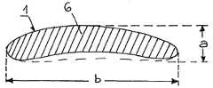
또 다른 바람직한 실시예에서, 상기 나선의 중심축에 본질적으로 직교하는 단면은 측부 a 및 b와 직교하며, 더 큰 측부인 b가 상기 나선의 바깥과 내부면을 향하게 된다. a:b의 비율은 0.50 보다 작아야 하며, 0.35 보다 작은 것이 바람직하다. 상기 직교하는 단면은 더 작은 측부인 a측에서 잘려지는 것이 바람직하다.In another preferred embodiment, the cross section essentially orthogonal to the central axis of the helix is orthogonal to the sides a and b, with the larger side b facing the outer and inner faces of the helix. The ratio of a: b should be less than 0.50, preferably less than 0.35. The orthogonal cross section is preferably cut off at the a side, which is the smaller side.
또 다른 바람직한 실시예에서, 상기 나선의 제1단부에 가까운 부분은 상기 나선의 제2단부에 가까운 부분보다 더 두껍다. 이와 같이 함으로써 상기 나선 네일을 붙잡고 조작할 수 있는 핸들을 부착할 수 있게 된다.In another preferred embodiment, the portion close to the first end of the helix is thicker than the portion close to the second end of the helix. By doing in this way, the handle which can catch and operate the said spiral nail can be attached.
또 다른 바람직한 실시예에서, 상기 나선의 중심축은 직선이다.In another preferred embodiment, the central axis of the helix is a straight line.
또 다른 바람직한 실시예에서, 상기 나선의 중심축에 직교하는 단면은 최대 치수가 5에서 14mm의 범위에 있으며, 상기 원통 또는 상기 나선의 길이는 200에서 500mm의 범위에 있다.In another preferred embodiment, the cross section orthogonal to the central axis of the helix has a maximum dimension in the range of 5 to 14 mm and the length of the cylinder or the helix is in the range of 200 to 500 mm.
또 다른 바람직한 실시예에서, 상기 임플란트에는 고정나사를 위한 측면 홀이 형성된다.In another preferred embodiment, the implant has a side hole for a set screw.
이하에서 본 발명은 도면을 참조하여 더욱 상세하게 설명된다.Hereinafter, the present invention will be described in more detail with reference to the drawings.
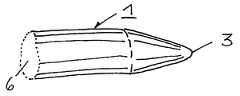
도 1은 나선형 네일 형태로 형성한 본 발명에 따른 기구의 사시도이다.1 is a perspective view of a mechanism according to the invention formed in the form of a spiral nail.
도 2는 나선형 플레이트 형태로 형성한 본 발명에 따른 기구의 사시도이다.2 is a perspective view of a mechanism according to the invention formed in the form of a spiral plate.
도 3은 도 1의 네일의 상세도이다.3 is a detail of the nail of FIG. 1.
도 4는 도 2의 플레이트의 상세도이다.4 is a detail of the plate of FIG. 2.
도 5는 도 1의 네일의 직교 단면도이다.5 is an orthogonal cross-sectional view of the nail of FIG. 1.
도 6은 네일의 직교단면의 변형례이다.6 is a modification of the orthogonal cross section of the nail.
도 7은 네일의 직교단면의 다른 변형례이다.7 is another modification of the orthogonal cross section of the nail.
본 발명에 따른 뼈합성기구를 골수내부용 네일의 형태로 예를 도 1에 나타내로다. 상기 기구는 수직형태를 보면 중심축(5)과, 제1단부(2)와, 제2단부(3)를 구비한다. 상기 기구(1)의 모양은 기하학적으로 잘 알려진 나선의 형태에 기초를 두고 있다. 도 1에 나타난 상기 나선이 이루는 외부면은 상기 나선과 동일한 중심축(5)을 갖는 원통(4)상이다. 상기 나선의 중심축(5)은 직선이다. 상기 나선은 540°이하, 바람직하게는 360°이하로 회전한다. 전형적으로는 240°로 회전한다. 상기 원통(4)의 반경 r 은 10에서 50mm의 범위에 있도록 하며, 15에서 30mm가 바람직하다. 상기 나선의 피치 p 는 100에서 1500mm의 범위이며, 300에서 1000mm 의 범위가 바람직하다. 도 5에 도시된 바와 같이, 상기 나선의 중심축(5)에 직교하는 단면의 형태는 원, 즉 상기 나선은 원통형 봉의 형태로 만들어진다. 대안적으로 도 6 및 7에 도시된 바와 같이 상기 단면은 사각형 또는 별 모양의 형태를 가질 수도 있다 (혹은 홈이 파진 형태일 수도 있다.).An example of a bone synthesis apparatus according to the present invention in the form of an intramedullary nail is shown in FIG. 1. The instrument has a central axis 5, a
본 발명의 다른 실시예가 도 2에 도시되어 있다. 도 1과 비교해 볼 때 중심축(5)에 직교하는 단면이 원이 아닌 사각형이라는 점에 다르다. 즉, 상기 나선이 납작한 막대기 형태로 만들어진다. 특히, 상기 나선의 중심축(5)에 직교하는 단면(6)은 측부 a 및 b와 직교하며, 더 큰 측부인 b가 상기 나선의 바깥과 내부면을 향하게 된다. 사각형의 형태 대신에 상기 단면을 a/2 및 b/2가 타원체의 단축에 해당하는 타원형이 될 수도 있을 것이다. a:b의 비율은 0.50 보다 작아야 하며, 0.35 보다 작은 것이 바람직하다.Another embodiment of the invention is shown in FIG. 2. Compared with FIG. 1, the cross section orthogonal to the central axis 5 is different from the circle rather than the circle. That is, the spiral is made in the form of a flat bar. In particular, the
상기 나선의 제1단부(2)에 가까운 부분은 상기 나선의 제2단부(3)에 가까운 부분보다 더 두껍다. 이와 같이 함으로써 상기 기구(1)를 붙잡고 조작할 수 있는 핸들을 부착할 수 있게 된다.The portion close to the
상기 중심축(5)에 직교하는 단면은 최대 치수가 5에서 14mm의 범위를 가진다.The cross section orthogonal to the central axis 5 has a maximum dimension in the range of 5 to 14 mm.
도 3에 도시된 바와 같이, 상기 기구(1)의 제2단부(3)는 뾰족하게 형성되어 뼈 속에 침투되는 것을 더욱 용이하게 할 수 있다.As shown in FIG. 3, the
도 4에 도신된 바와 같이, 상기 기구(1)의 직교하는 단면은 더 작은 측부인 a측에서 잘려지는 것이 바람직하다.As shown in Fig. 4, the orthogonal cross section of the
도 5 내지 7은 본 발명에 따른 네일의 서로 다른 단면들을 보여준다.5 to 7 show different cross sections of the nail according to the invention.
본 발명에 따른 기구는 그 사용 목적에 따라 어떠한 적절한 물질로도 만들어질 수 있다. 금속으로 그러한 기구들을 제조할 수 있는데, 예를 들면 적절한 스테인레스강, 티타늄 또는 특히 복합체인 고분자물질 등으로 제조할 수 있을 것이다.
The appliance according to the invention can be made of any suitable material, depending on its purpose of use. Such devices may be made of metal, for example made of suitable stainless steel, titanium or in particular a polymeric material which is a composite.
Claims (18)
Translated fromKoreanApplications Claiming Priority (1)
| Application Number | Priority Date | Filing Date | Title |
|---|---|---|---|
| PCT/CH2001/000276WO2002089683A1 (en) | 2001-05-03 | 2001-05-03 | Osteosynthetic device |
Publications (2)
| Publication Number | Publication Date |
|---|---|
| KR20040012780A KR20040012780A (en) | 2004-02-11 |
| KR100771677B1true KR100771677B1 (en) | 2007-10-31 |
Family
ID=4358201
Family Applications (1)
| Application Number | Title | Priority Date | Filing Date |
|---|---|---|---|
| KR1020037014276AExpired - Fee RelatedKR100771677B1 (en) | 2001-05-03 | 2001-05-03 | Skeleton |
Country Status (15)
| Country | Link |
|---|---|
| US (1) | US20040215194A1 (en) |
| EP (1) | EP1383436B1 (en) |
| JP (1) | JP4611614B2 (en) |
| KR (1) | KR100771677B1 (en) |
| CN (1) | CN1235551C (en) |
| AR (1) | AR033270A1 (en) |
| AT (1) | ATE306856T1 (en) |
| BR (1) | BR0116998B1 (en) |
| CA (1) | CA2446779C (en) |
| CZ (1) | CZ20032934A3 (en) |
| DE (1) | DE60114244T2 (en) |
| MX (1) | MXPA03010005A (en) |
| NO (1) | NO20034869L (en) |
| SK (1) | SK13402003A3 (en) |
| WO (1) | WO2002089683A1 (en) |
Families Citing this family (11)
| Publication number | Priority date | Publication date | Assignee | Title |
|---|---|---|---|---|
| NZ542503A (en)* | 2003-03-28 | 2006-11-30 | Synthes Ag | Locking screw with crooked shank for medullary pin |
| CH697414B1 (en)* | 2005-05-13 | 2008-09-30 | Synthes Gmbh | Device for the temporary splinting of toes. |
| RU2317037C1 (en)* | 2006-07-12 | 2008-02-20 | Александр Петрович Букреев | Method for surgical treatment of fractures and fractures-dislocations of collum brachium |
| CA2781407A1 (en) | 2008-01-14 | 2009-07-23 | Michael P. Brenzel | Apparatus and methods for fracture repair |
| DE102008017741B4 (en)* | 2008-04-07 | 2014-03-20 | H & R Spezialfedern Gmbh & Co. Kg | Tool for screwing and unscrewing a coil spring in and out of the cavity of a long bone |
| US20110178520A1 (en) | 2010-01-15 | 2011-07-21 | Kyle Taylor | Rotary-rigid orthopaedic rod |
| WO2011091052A1 (en) | 2010-01-20 | 2011-07-28 | Kyle Taylor | Apparatus and methods for bone access and cavity preparation |
| WO2011112615A1 (en) | 2010-03-08 | 2011-09-15 | Krinke Todd A | Apparatus and methods for securing a bone implant |
| TWI434667B (en)* | 2011-03-30 | 2014-04-21 | Metal Ind Res & Dev Ct | Medical instrument with three dimensional fixation shape memory intramedullary nail |
| CN105939677A (en) | 2013-12-12 | 2016-09-14 | 康文图斯整形外科公司 | Tissue displacement tools and methods |
| WO2019010252A2 (en) | 2017-07-04 | 2019-01-10 | Conventus Orthopaedics, Inc. | APPARATUS AND METHODS FOR TREATING BONES |
Citations (5)
| Publication number | Priority date | Publication date | Assignee | Title |
|---|---|---|---|---|
| GB1274470A (en) | 1968-06-17 | 1972-05-17 | William Xavier Halloran | Improvements in or relating to intramedullary fixation devices |
| US3709218A (en) | 1970-04-24 | 1973-01-09 | W Halloran | Combination intramedullary fixation and external bone compression apparatus |
| EP0094039A1 (en)* | 1982-05-12 | 1983-11-16 | Oscar Scaglietti | Endomedullar nail for long bones |
| DE3835682A1 (en)* | 1988-10-20 | 1990-04-26 | Labitzke Reiner Prof Dr Med Ha | Device for stabilizing fractures of tubular bones and of joints |
| US6174312B1 (en) | 1996-09-05 | 2001-01-16 | Karl Laminger | Helical wire |
Family Cites Families (8)
| Publication number | Priority date | Publication date | Assignee | Title |
|---|---|---|---|---|
| US5055104A (en)* | 1989-11-06 | 1991-10-08 | Surgical Dynamics, Inc. | Surgically implanting threaded fusion cages between adjacent low-back vertebrae by an anterior approach |
| US5263953A (en)* | 1991-12-31 | 1993-11-23 | Spine-Tech, Inc. | Apparatus and system for fusing bone joints |
| US5423817A (en)* | 1993-07-29 | 1995-06-13 | Lin; Chih-I | Intervertebral fusing device |
| US5626613A (en)* | 1995-05-04 | 1997-05-06 | Arthrex, Inc. | Corkscrew suture anchor and driver |
| US5662683A (en)* | 1995-08-22 | 1997-09-02 | Ortho Helix Limited | Open helical organic tissue anchor and method of facilitating healing |
| US5766174A (en)* | 1995-09-26 | 1998-06-16 | Orthologic Corporation | Intramedullary bone fixation device |
| US6953462B2 (en)* | 2000-10-05 | 2005-10-11 | The Cleveland Clinic Foundation | Apparatus for implantation into bone |
| DE102004063396B4 (en)* | 2004-12-23 | 2006-11-02 | Michael Zielsdorf | Mark Nagel |
- 2001
- 2001-05-03JPJP2002586825Apatent/JP4611614B2/ennot_activeExpired - Fee Related
- 2001-05-03KRKR1020037014276Apatent/KR100771677B1/ennot_activeExpired - Fee Related
- 2001-05-03WOPCT/CH2001/000276patent/WO2002089683A1/enactiveIP Right Grant
- 2001-05-03ATAT01923465Tpatent/ATE306856T1/ennot_activeIP Right Cessation
- 2001-05-03EPEP01923465Apatent/EP1383436B1/ennot_activeExpired - Lifetime
- 2001-05-03BRBRPI0116998-0Apatent/BR0116998B1/ennot_activeIP Right Cessation
- 2001-05-03SKSK1340-2003Apatent/SK13402003A3/enunknown
- 2001-05-03DEDE60114244Tpatent/DE60114244T2/ennot_activeExpired - Lifetime
- 2001-05-03MXMXPA03010005Apatent/MXPA03010005A/enunknown
- 2001-05-03CACA002446779Apatent/CA2446779C/ennot_activeExpired - Fee Related
- 2001-05-03CNCNB018231705Apatent/CN1235551C/ennot_activeExpired - Fee Related
- 2001-05-03CZCZ20032934Apatent/CZ20032934A3/enunknown
- 2002
- 2002-04-26ARARP020101535Apatent/AR033270A1/ennot_activeApplication Discontinuation
- 2003
- 2003-10-29USUS10/694,846patent/US20040215194A1/ennot_activeAbandoned
- 2003-10-31NONO20034869Apatent/NO20034869L/ennot_activeApplication Discontinuation
Patent Citations (5)
| Publication number | Priority date | Publication date | Assignee | Title |
|---|---|---|---|---|
| GB1274470A (en) | 1968-06-17 | 1972-05-17 | William Xavier Halloran | Improvements in or relating to intramedullary fixation devices |
| US3709218A (en) | 1970-04-24 | 1973-01-09 | W Halloran | Combination intramedullary fixation and external bone compression apparatus |
| EP0094039A1 (en)* | 1982-05-12 | 1983-11-16 | Oscar Scaglietti | Endomedullar nail for long bones |
| DE3835682A1 (en)* | 1988-10-20 | 1990-04-26 | Labitzke Reiner Prof Dr Med Ha | Device for stabilizing fractures of tubular bones and of joints |
| US6174312B1 (en) | 1996-09-05 | 2001-01-16 | Karl Laminger | Helical wire |
Also Published As
| Publication number | Publication date |
|---|---|
| AR033270A1 (en) | 2003-12-10 |
| SK13402003A3 (en) | 2004-06-08 |
| HK1059871A1 (en) | 2004-07-23 |
| JP2004526535A (en) | 2004-09-02 |
| NO20034869D0 (en) | 2003-10-31 |
| JP4611614B2 (en) | 2011-01-12 |
| WO2002089683A8 (en) | 2003-11-13 |
| CN1505493A (en) | 2004-06-16 |
| BR0116998B1 (en) | 2010-07-13 |
| US20040215194A1 (en) | 2004-10-28 |
| NO20034869L (en) | 2004-01-02 |
| KR20040012780A (en) | 2004-02-11 |
| WO2002089683A1 (en) | 2002-11-14 |
| ATE306856T1 (en) | 2005-11-15 |
| EP1383436B1 (en) | 2005-10-19 |
| CA2446779A1 (en) | 2002-11-14 |
| CA2446779C (en) | 2009-08-11 |
| MXPA03010005A (en) | 2005-03-07 |
| EP1383436A1 (en) | 2004-01-28 |
| BR0116998A (en) | 2004-06-22 |
| CZ20032934A3 (en) | 2004-05-12 |
| DE60114244T2 (en) | 2006-07-06 |
| CN1235551C (en) | 2006-01-11 |
| DE60114244D1 (en) | 2005-11-24 |
Similar Documents
| Publication | Publication Date | Title |
|---|---|---|
| US9289220B2 (en) | Intramedullary fixation assembly and method of use | |
| EP0723764A1 (en) | Pin plate | |
| KR100771677B1 (en) | Skeleton | |
| EP1682008B1 (en) | A fixator for repairing of long bone fractures | |
| US20070288016A1 (en) | Bone support | |
| RU2289351C2 (en) | Intramedullary pin for performing trochanteric femur fracture osteosynthesis | |
| EP1792578A1 (en) | Implant and applicator for osteosynthesis of the elbow | |
| EP0517435A1 (en) | Intramedullary osteosynthetic device | |
| RU153331U1 (en) | DEVICE FOR INTRAMEDULAR OSTEOSYNTHESIS OF THE TIBERA | |
| RU91282U1 (en) | INTRAMEDOLLARY NAIL | |
| RU96756U1 (en) | PIN FOR INTRAMEDULAR OSTEOSYNTHESIS OF THE TIBERA | |
| RU2141805C1 (en) | Device for osteosynthesis | |
| RU2110230C1 (en) | Fixing device for performing osteosynthesis of neck of the femur | |
| RU2254825C2 (en) | Device for carrying out tubular bone osteosynthesis | |
| RU2757153C1 (en) | Intramedullary rod for external and transosseous osteosynthesis | |
| SU1426557A1 (en) | Intraosseus fixative | |
| RU2410058C1 (en) | Precision osteoperforation device | |
| RU208208U1 (en) | Proximal elbow plate | |
| US20230027816A1 (en) | Oblique diaphyseal osteotomy system for metatarsal shortening | |
| RU2716506C1 (en) | Detachable nozzle to screwdriver | |
| RU2284786C1 (en) | Surgical method and device for treating the cases of clavicle fracture in the middle one third | |
| RU2154434C1 (en) | Fixing member for performing femur osteosynthesis | |
| HK1059871B (en) | Osteosynthetic device | |
| RU2254089C2 (en) | Fixing member for performing osteosynthesis | |
| RU2256417C2 (en) | Osteoperforator device |
Legal Events
| Date | Code | Title | Description |
|---|---|---|---|
| PA0105 | International application | St.27 status event code:A-0-1-A10-A15-nap-PA0105 | |
| P11-X000 | Amendment of application requested | St.27 status event code:A-2-2-P10-P11-nap-X000 | |
| P13-X000 | Application amended | St.27 status event code:A-2-2-P10-P13-nap-X000 | |
| PG1501 | Laying open of application | St.27 status event code:A-1-1-Q10-Q12-nap-PG1501 | |
| A201 | Request for examination | ||
| P11-X000 | Amendment of application requested | St.27 status event code:A-2-2-P10-P11-nap-X000 | |
| P13-X000 | Application amended | St.27 status event code:A-2-2-P10-P13-nap-X000 | |
| PA0201 | Request for examination | St.27 status event code:A-1-2-D10-D11-exm-PA0201 | |
| N231 | Notification of change of applicant | ||
| PN2301 | Change of applicant | St.27 status event code:A-3-3-R10-R13-asn-PN2301 St.27 status event code:A-3-3-R10-R11-asn-PN2301 | |
| P11-X000 | Amendment of application requested | St.27 status event code:A-2-2-P10-P11-nap-X000 | |
| P13-X000 | Application amended | St.27 status event code:A-2-2-P10-P13-nap-X000 | |
| E902 | Notification of reason for refusal | ||
| PE0902 | Notice of grounds for rejection | St.27 status event code:A-1-2-D10-D21-exm-PE0902 | |
| P11-X000 | Amendment of application requested | St.27 status event code:A-2-2-P10-P11-nap-X000 | |
| P13-X000 | Application amended | St.27 status event code:A-2-2-P10-P13-nap-X000 | |
| E701 | Decision to grant or registration of patent right | ||
| PE0701 | Decision of registration | St.27 status event code:A-1-2-D10-D22-exm-PE0701 | |
| GRNT | Written decision to grant | ||
| PR0701 | Registration of establishment | St.27 status event code:A-2-4-F10-F11-exm-PR0701 | |
| PR1002 | Payment of registration fee | St.27 status event code:A-2-2-U10-U12-oth-PR1002 Fee payment year number:1 | |
| PG1601 | Publication of registration | St.27 status event code:A-4-4-Q10-Q13-nap-PG1601 | |
| PR1001 | Payment of annual fee | St.27 status event code:A-4-4-U10-U11-oth-PR1001 Fee payment year number:4 | |
| PR1001 | Payment of annual fee | St.27 status event code:A-4-4-U10-U11-oth-PR1001 Fee payment year number:5 | |
| FPAY | Annual fee payment | Payment date:20121009 Year of fee payment:6 | |
| PR1001 | Payment of annual fee | St.27 status event code:A-4-4-U10-U11-oth-PR1001 Fee payment year number:6 | |
| FPAY | Annual fee payment | Payment date:20130924 Year of fee payment:7 | |
| PR1001 | Payment of annual fee | St.27 status event code:A-4-4-U10-U11-oth-PR1001 Fee payment year number:7 | |
| LAPS | Lapse due to unpaid annual fee | ||
| PC1903 | Unpaid annual fee | St.27 status event code:A-4-4-U10-U13-oth-PC1903 Not in force date:20141025 Payment event data comment text:Termination Category : DEFAULT_OF_REGISTRATION_FEE | |
| PC1903 | Unpaid annual fee | St.27 status event code:N-4-6-H10-H13-oth-PC1903 Ip right cessation event data comment text:Termination Category : DEFAULT_OF_REGISTRATION_FEE Not in force date:20141025 |