KR100770833B1 - Optical sensor module - Google Patents
Optical sensor moduleDownload PDFInfo
- Publication number
- KR100770833B1 KR100770833B1KR1020060022231AKR20060022231AKR100770833B1KR 100770833 B1KR100770833 B1KR 100770833B1KR 1020060022231 AKR1020060022231 AKR 1020060022231AKR 20060022231 AKR20060022231 AKR 20060022231AKR 100770833 B1KR100770833 B1KR 100770833B1
- Authority
- KR
- South Korea
- Prior art keywords
- light
- waveguide
- photodetector
- body part
- light source
- Prior art date
- Legal status (The legal status is an assumption and is not a legal conclusion. Google has not performed a legal analysis and makes no representation as to the accuracy of the status listed.)
- Active
Links
- DMICIZVPSKKBDO-UHFFFAOYSA-NC=C1CNCCC1Chemical compoundC=C1CNCCC1DMICIZVPSKKBDO-UHFFFAOYSA-N0.000description1
Images


Classifications
- A—HUMAN NECESSITIES
- A61—MEDICAL OR VETERINARY SCIENCE; HYGIENE
- A61G—TRANSPORT, PERSONAL CONVEYANCES, OR ACCOMMODATION SPECIALLY ADAPTED FOR PATIENTS OR DISABLED PERSONS; OPERATING TABLES OR CHAIRS; CHAIRS FOR DENTISTRY; FUNERAL DEVICES
- A61G15/00—Operating chairs; Dental chairs; Accessories specially adapted therefor, e.g. work stands
- A61G15/02—Chairs with means to adjust position of patient; Controls therefor
- A—HUMAN NECESSITIES
- A61—MEDICAL OR VETERINARY SCIENCE; HYGIENE
- A61B—DIAGNOSIS; SURGERY; IDENTIFICATION
- A61B5/00—Measuring for diagnostic purposes; Identification of persons
- A61B5/0059—Measuring for diagnostic purposes; Identification of persons using light, e.g. diagnosis by transillumination, diascopy, fluorescence
- A—HUMAN NECESSITIES
- A61—MEDICAL OR VETERINARY SCIENCE; HYGIENE
- A61B—DIAGNOSIS; SURGERY; IDENTIFICATION
- A61B5/00—Measuring for diagnostic purposes; Identification of persons
- A61B5/02—Detecting, measuring or recording for evaluating the cardiovascular system, e.g. pulse, heart rate, blood pressure or blood flow
- A61B5/024—Measuring pulse rate or heart rate
- A61B5/02416—Measuring pulse rate or heart rate using photoplethysmograph signals, e.g. generated by infrared radiation
- A61B5/02427—Details of sensor
- A—HUMAN NECESSITIES
- A61—MEDICAL OR VETERINARY SCIENCE; HYGIENE
- A61B—DIAGNOSIS; SURGERY; IDENTIFICATION
- A61B5/00—Measuring for diagnostic purposes; Identification of persons
- A61B5/48—Other medical applications
- A61B5/4869—Determining body composition
- A61B5/4872—Body fat
- A—HUMAN NECESSITIES
- A61—MEDICAL OR VETERINARY SCIENCE; HYGIENE
- A61G—TRANSPORT, PERSONAL CONVEYANCES, OR ACCOMMODATION SPECIALLY ADAPTED FOR PATIENTS OR DISABLED PERSONS; OPERATING TABLES OR CHAIRS; CHAIRS FOR DENTISTRY; FUNERAL DEVICES
- A61G15/00—Operating chairs; Dental chairs; Accessories specially adapted therefor, e.g. work stands
- A61G15/10—Parts, details or accessories
- A61G15/12—Rests specially adapted therefor, e.g. for the head or feet
- A61G15/125—Head-rests
Landscapes
- Health & Medical Sciences (AREA)
- Life Sciences & Earth Sciences (AREA)
- Animal Behavior & Ethology (AREA)
- General Health & Medical Sciences (AREA)
- Public Health (AREA)
- Veterinary Medicine (AREA)
- Biomedical Technology (AREA)
- Molecular Biology (AREA)
- Pathology (AREA)
- Engineering & Computer Science (AREA)
- Physics & Mathematics (AREA)
- Heart & Thoracic Surgery (AREA)
- Medical Informatics (AREA)
- Biophysics (AREA)
- Surgery (AREA)
- Cardiology (AREA)
- Physiology (AREA)
- Oral & Maxillofacial Surgery (AREA)
- Measurement Of The Respiration, Hearing Ability, Form, And Blood Characteristics Of Living Organisms (AREA)
- Investigating Or Analysing Materials By Optical Means (AREA)
Abstract
Translated fromKoreanDescription
Translated fromKorean도 1은 종래 생체 신호 측정을 위한 광센서 모듈을 도시한 도면,1 is a view showing an optical sensor module for measuring a conventional bio-signal,
도 2는 종래 광센서 모듈을 도시한 도면,2 is a view showing a conventional optical sensor module,
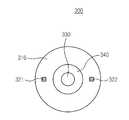
도 3a는 본 발명의 제1 실시 예에 따른 광센서 모듈을 도시한 도면,3A is a view illustrating an optical sensor module according to a first embodiment of the present invention;
도 3b는 도 3a에 도시된 광센서 모듈의 단면을 도시한 도면,3b is a cross-sectional view of the optical sensor module shown in FIG. 3a;
도 4a는 본 발명의 제2 실시 예에 따른 광센서 모듈을 도시한 도면,4A is a view illustrating an optical sensor module according to a second embodiment of the present invention;
도 4b는 도 4a에 도시된 광센서 모듈의 단면을 도시한 도면,4B is a cross-sectional view of the optical sensor module illustrated in FIG. 4A;
도 5a는 본 발명의 제3 실시 예에 따른 광센서 모듈을 도시한 도면,5A is a view showing an optical sensor module according to a third embodiment of the present invention;
도 5b는 도 5a에 A~B를 절개한 단면을 도시한 도면,Figure 5b is a view showing a cross section taken A to B in Figure 5a,
도 6a는 본 발명의 제4 실시 예에 따른 광센서 모듈을 도시한 도면,6A is a view illustrating an optical sensor module according to a fourth embodiment of the present invention;
도 6b는 도 6a에 도시된 A'~B'을 절개한 단면을 도시한 도면.6B is a cross-sectional view taken along the line A ′ to B ′ of FIG. 6A;
본 발명은 생체 신호 측정을 위한 센서 모듈에 관한 발명으로서, 특히 광학적 생체 신호 측정을 위한 광센서 모듈에 관한 발명이다.The present invention relates to a sensor module for measuring a biological signal, and more particularly to an optical sensor module for measuring an optical biosignal.
근래 들어 체지방, 맥박 및 혈류량과 같은 생체 신호의 측정을 통해서 각 개인의 건강 상태 및 체력 상태를 파악할 수 있는 다양한 형태의 생체 신호 측정용 센서 모듈이 사용되고 있다.Recently, various types of sensor modules for measuring bio signals have been used to measure health status and physical condition of each individual through measurement of bio signals such as body fat, pulse and blood flow.
생체 신호 측정을 위한 센서 모듈은 신체 부위 중 원하는 부위에 광을 입사시킨 후 반사되어 돌아온 광의 세기로부터 체지방 두께 및 비율과, 맥박 및 혈류 파형을 구하는 광학 방식의 센서 모듈이 널리 사용되고 있다. 광을 이용한 생체 신호 측정은 대상이 되는 신체 구성 성분에 따른 광의 흡수 스펙트럼 차이를 이용한 측정으로서, 대상이 되는 신체 부위에 입사된 광이 다중 산란을 거친 후 측정된 광의 세기로부터 신체 특성을 파악한다.As the sensor module for measuring the biological signal, an optical sensor module that obtains body fat thickness and ratio, pulse and blood flow waveforms from the intensity of the reflected light after incident light on a desired part of the body part is widely used. The biosignal measurement using light is a measurement using an absorption spectrum difference of light according to a body component of interest, and the body characteristic is determined from the intensity of light measured after the light incident on the body part of the subject undergoes multiple scattering.
광을 이용한 체지방 측정 기술은 이미 상용화되어 의료용 또는 미용의 목적으로 사용되고 있으며, 이와 관련된 주요 특허로는 G.K.Rosenthal 등에 의해 미국 특허 등록된 US 4,633,087(Near infrared apparatus for measurement of organic constituents of material)과, R.D. Rosenthal 등에 의해 미국 특허 등록된 US 4,850,365 등이 있다. 종래 생체 신호 측정을 위한 모듈은 근적외 파장의 광을 대상이 되는 신체 부위에 투사한 후 반사되는 광의 세기로부터 체지방을 측정하는 방식으로서, US4,633,087은 서로 다른 파장을 갖는 하나 이상의 광들을 이용한 측정 방식이고, US4,850,365의 발명은 하나의 광원으로 체지방만을 측정하는 특허이다.Body fat measurement technology using light has already been commercialized and used for medical or cosmetic purposes, and related patents are US 4,633,087 (Near infrared apparatus for measurement of organic constituents of material) and G.K.Rosenthal et al., And R.D. US Pat. No. 4,850,365 to Rosenthal et al. Conventional biosignal measurement module is a method for measuring body fat from the intensity of the reflected light after projecting the light of the near infrared wavelength to the target body part, US4,633,087 is measured using one or more lights having different wavelengths Method, and the invention of US Pat. No. 4,850,365 is a patent for measuring only body fat with one light source.
상술한 발명들은 생체 신호 측정을 위한 신체 대상에서 다중 산란된 광의 세기로부터 생체 신호를 산출하기 위해서 사용된 광의 파장과, 대상자의 체중 나이, 성별, 키 등의 다양한 변수를 포함하는 회귀 식이 적용되고 있다.In the above-described inventions, a regression equation including a wavelength of light used to calculate a biosignal from an intensity of multi-scattered light and a weight, age, gender, and height of a subject are applied to a body object for measuring a biosignal. .
통상의 광센서 모듈은 측정 대상 부위에 균일한 세기의 광을 조사하기 위해서 복수의 광원들을 사용하거나, 측정 대상인 신체 부위에 접하는 면의 직경이 직경과 수직 방향으로의 길이보다 짧은 원통형의 프로브(probe) 구조가 제안되고 있다. 즉, 종래 광센서 모듈은 측정에 사용되는 광을 일정 길이 이상 도파시킨 후 대상 신체 부위에 투사시킴으로써 광을 균일하게 조사하는 방법을 택하고 있다.Conventional optical sensor module uses a plurality of light sources to irradiate light of uniform intensity to the area to be measured, or a cylindrical probe whose diameter of the surface contacting the body part to be measured is shorter than the length in the direction perpendicular to the diameter ) Structure has been proposed. In other words, the conventional optical sensor module is a method of uniformly irradiating light by guiding the light to be measured for a predetermined length or more and then projecting to the target body part.
도 1은 종래 생체 신호 특히 맥파, 혈중 내 산소포화량 등의 측정을 위한 광센서 모듈을 도시한 도면으로서, 도 1은 생체 신호 측정을 위한 대상 신체에 접하게 위치된 상태(100)를 나타낸다. 상기 광센서 모듈(120)은 하우징(123)의 내부에 광원(121)과, 상기 광원(121)에서 출사된 후 대상 신체에서 반사된 광의 세기를 검출해내는 광검출기(122)를 포함한다.FIG. 1 illustrates a conventional optical sensor module for measuring a conventional bio-signal, in particular pulse wave and oxygen saturation in blood, and FIG. 1 shows a
도 2는 체지방 측정을 위한 종래 광센서 모듈의 또 다른 구성을 도시한 도면이다. 도 2를 참조하면, 하우징(124')의 내부에 각 홈(123')에 대상 신체 부위에 조사할 광을 생성하는 광원들(121a',121b')과, 대상 신체 부위에서 반사된 광의 세기를 검출해내기 위한 광 검출기(122')를 포함한다. 상기 광센서 모듈은 상기 광검출기(122')를 중심으로 대칭되게 위치된 광원들(121a',121b')과, 상기 각 광원들(121a',121b')이 대상 신체 부위에 접하는 부분의 면에 수직한 길이 방향으로 길게 형성함으로써 균일한 세기의 광을 대상 신체 부위에 조사할 수 있다.2 is a view showing another configuration of a conventional optical sensor module for body fat measurement. 2,
도 2는 US 4,633,087과 US4,850,365에 도시된 프로브 형태의 센서 모듈을 소형화한 것으로 보다 높은 정확성과 재현성 있는 측정을 위해서 상술한 두 특허에 기재된 바와 같이 프로브의 길이가 대상 신체 부위에 접하는 부분의 직경보다 수 ㎝ 이상 크게 형성되는 것이 바람직하나, 상술한 구조는 휴대 장치에 장착이 용이하지 않은 문제가 있다.2 is a miniaturized probe module sensor module shown in US Pat. No. 4,633,087 and US Pat. No. 4,850,365. The diameter of the portion where the length of the probe is in contact with the target body part, as described in the two patents described above, for higher accuracy and reproducible measurement. Although it is preferable to form larger than several centimeters, the structure mentioned above has a problem that it is not easy to mount to a portable device.
본 발명은 측정 부위에 균일한 세기의 광을 조사할 수 있고 소형화된 생체 신호 측정을 위한 광센서 모듈을 제공하는 데 목적이 있다.An object of the present invention is to provide a light sensor module for irradiating light of uniform intensity to a measurement site and miniaturized biosignal measurement.
본 발명에 따른 대상 신체 부위의 생체 신호를 검출해내기 위한 광센서 모듈은,Optical sensor module for detecting a bio-signal of the target body part according to the present invention,
광을 생성하기 위한 적어도 하나의 광원과;At least one light source for generating light;
대상 신체 부위에서 반사된 광의 세기를 감시하기 위한 광검출기와;A photodetector for monitoring the intensity of light reflected from the target body part;
대상 신체 부위에 접하며 상기 광검출기의 수광면이 노출된 제1 면과 상기 제1 면의 타 측에 위치된 제2 면을 구비하며 상기 광원에서 생성된 광을 상기 제1 면 전체에 균일한 세기로 출사시키기 위한 도파로를 포함한다.A first surface in contact with a target body part and having a light-receiving surface of the photodetector exposed thereon and a second surface located on the other side of the first surface, and having uniform intensity of light generated from the light source throughout the first surface; It includes a waveguide for exiting.
이하에서는 첨부도면들을 참조하여 본 발명의 실시 예를 상세히 설명하기로 한다. 본 발명을 설명함에 있어서, 관련된 공지기능, 혹은 구성에 대한 구체적인 설명은 본 발명의 요지를 모호하지 않게 하기 위하여 생략한다.Hereinafter, with reference to the accompanying drawings will be described an embodiment of the present invention; In describing the present invention, detailed descriptions of related well-known functions or configurations are omitted in order not to obscure the subject matter of the present invention.
도 3a는 본 발명의 제1 실시 예에 따른 광센서 모듈을 도시한 도면이고, 도 3b는 도 3a에 도시된 광센서 모듈의 단면을 도시한 도면이다. 도 3a 및 도 3b를 참 조하면, 본 실시 예에 따른 광센서 모듈(200)은 광을 생성하기 위한 적어도 하나의 광원(221,222)과, 대상 신체 부위에서 반사된 광의 세기를 검출하기 위한 광검출기(230)와, 대상 신체 부위에 접하며 상기 광검출기의 수광면이 노출된 제1 면(210a)과 상기 제1 면(210a)의 타 측에 위치된 제2 면(210b)을 구비하며 상기 각 광원(221,222)에서 생성된 광을 상기 제1 면(210a) 전체에 걸쳐서 균일한 세기로 출사시키기 위한 도파로(210)와, 차단층(240)을 포함한다. 상기 차단층(240)은 상기 광검출기의 둘레를 둘러싸는 링(ring) 형태로 형성되고, 상기 광원(221,222)은 600㎚ 파장 대역의 광을 생성할 수 있는 발광 다이오드 또는 측면 발광 다이오드가 사용될 수 있다.3A is a diagram illustrating an optical sensor module according to a first embodiment of the present invention, and FIG. 3B is a cross-sectional view of the optical sensor module illustrated in FIG. 3A. 3A and 3B, the
상기 광검출기(230)는 상기 도파로(210)의 중심부에 수광면이 노출되도록 삽입되며, 상기 차단층(240)은 광검출기의 둘레의 둘러싸며 상기 도파로(210)로부터 상기 광검출기(230)로 직접 입사되는 광을 차단한다. 상기 광검출기(230)는 상기 도파로(210)의 제1 면(210a)에 노출된 수광면을 통해서 생체 신호 측정의 대상인 신체 부위에서 반사된 광의 세기를 검출한다.The
상기 도파로(210)는 그 중심부에 상기 광검출기(230)를 둘러싸는 차단층(240)이 삽입되며, 상기 제2 면(210b)에는 상기 제1 및 제2 면(210a,210b) 사이의 측면에 위치된 광원(221,222)에서 생성된 광을 균일한 세기로 대상 신체 부위로 반사시키기 위한 확산 패턴들(211,212)이 형성된다. 상기 도파로(210)는 도파되는 광의 파장 범위에서 투명한 특성을 갖는 아크릴(acrylic) 또는 폴리카보네이트(Polycarbonate) 등의 재질로 이루어지며 링(ring) 형태로 압출 성형 등에 의해서 성형 될 수 있다. 상기 도파로(210) 내부에 입사된 광은 굴절률 차에 의해 내부 전반사 되어 진행되며, 상기 확산 패턴(211,212)에 의해 제1 면(210a) 측으로 반사될 수 있다. 그 외에도, 상기 도파로(210)의 제1 면(210a) 상에는 출사되는 광의 방향을 조절하기 위한 프리즘 시트(Prism sheet; 미도시)가 안착 될 수 있으며, 상기 제2 면(210b)dml 하부에는 상기 도파로(210)의 하부로 출사되는 광을 측정 부위와 접하는 제1 면(210)의 방향으로 반사시키기 위한 반사 시트(reflection sheet;미도시)를 사용하는 것이 바람직하다.The
상기 확산 패턴(211,212)은 상기 광을 대상 신체 부위에 균일한 세기로 조사시키기 위해서, 패턴의 밀도를 조절할 수 있다. 즉, 본 실시 예는 상기 확산 패턴(211,212)의 밀도를 상기 광원(221,222)으로부터 멀어질수록 상기 광원(221,222)에 인접한 부분의 확산 패턴의 밀도보다 밀하게 형성함으로써 도파로(210) 전체에 걸쳐서 균일한 광을 조사할 수 있다. 즉, 상기 확산 패턴(211,212)의 크기와 밀도는 상기 광원(221,222)으로부터 상대 거리 또는 도파로(210) 내 위치에 의해 결정될 수 있다. 상기 확산 패턴(211,212)은 미세한 크기를 갖는 원뿔, 반구, 육면체, 삼각뿔, 사각뿔과 같은 다양한 형태의 입체 구조로 형성될 수 있으며, 상기 도파로(210)에 음각 또는 양각의 형태로 레이저 가동 또는 금형 제작에 의해 형성될 수 있다. 또한, 상기 확산 패턴(211,212)은 중 하나의 형태로 형성될 수 있다. 상기 확산 패턴(211,212)은 도파로(210)의 길이와 입사되는 광의 각도 등의 조건에 따라서 반사되는 광의 각도 등에 따라서 그 형태 및 크기를 결정할 수 있다.The
상기 각 광원(221,222)은 상기 도파로(210)의 제1 및 제2 면(210a,210b) 사 이의 측면에 위치되며, 대상 신체 부위에 조사시키기 위한 광을 생성한다. 상기 각 광원(221,222)에서 생성된 광은 상기 도파로(210)를 따라 진행하며 상기 확산 패턴(211,212)에 의해 상기 제1 면(210a) 측으로 반사된다. 상기 제1 면(210a) 측으로 반사된 광은 균일한 세기로 대상 신체 부위에 조사된다.Each of the
생체 신호 측정을 위한 대상 신체 부위에서 다중 산란된 광은 상기 광검출기(230)로 입사된다. 상기 광검출기(230)에 입사된 광의 세기는 대상 신체 부위의 체지방 두께 또는 비율에 따라 다르며, 대상 신체 부위로 조사된 광의 기준 세기와 상기 광검출기(230)에서 측정된 광의 세기 비율을 회귀식을 이용해서 체지방 두께 또는 비율을 산출하게 된다.The multi-scattered light is incident on the
상술한 회귀식은 사용하는 광검출기 및 광의 파장 개수 등에 따라 다르고, 단일 파장의 광을 사용할 경우는 측정자의 성별, 몸무게, 나이, 키 등이 회귀식에 적용될 수 있다.The above regression equations vary depending on the photodetector used and the number of wavelengths of light, and when using a single wavelength of light, the gender, weight, age, height, etc. of the measurer may be applied to the regression equation.
도 4a는 본 발명의 제2 실시 예에 따른 광센서 모듈을 도시한 도면이고, 도 4b는 도 4a에 도시된 광센서 모듈의 단면을 도시한 도면이다. 도 4a 및 도 4b를 참조하면, 본 실시 예에 따른 광센서 모듈(300)은 광을 생성하기 위한 적어도 하나의 광원(321,322)과, 대상 신체 부위에서 반사된 광의 세기를 감시하기 위한 광검출기(330)와, 대상 신체 부위에 접하며 상기 광검출기(330)의 수광면이 노출된 제1 면(310a)과 상기 제1 면(310a)의 타 측에 위치된 제2 면(310b)을 구비하며 상기 각 광원(321,322)에서 생성된 광을 상기 제1 면(310a) 전체에 균일한 세기로 출사시키기 위한 도파로(310)와, 차단층(340)을 포함한다.4A is a diagram illustrating an optical sensor module according to a second exemplary embodiment of the present invention, and FIG. 4B is a cross-sectional view of the optical sensor module illustrated in FIG. 4A. 4A and 4B, the
상기 광검출기(330)는 상기 도파로(310)의 중심부에 수광면이 노출되도록 삽입되며, 상기 차단층(340)은 상기 광검출기(330)의 둘레의 둘러싸며 상기 도파로(310)로부터 상기 광검출기(330)로 직접 입사되는 광을 차단한다. 상기 광검출기(330)는 상기 도파로(310)의 제1 면(310a)에 노출된 수광면을 통해서 생체 신호 측정의 대상인 신체 부위에서 반사된 광의 세기를 검출한다.The
상기 도파로(310)는 그 중심부에 상기 광검출기(330) 및 상기 광검출기(330)를 둘러싸는 차단층(340)이 삽입되며, 상기 제2 면(310b) 상에는 상기 각 광원(321,322)에서 생성된 광을 균일한 세기로 대상 신체 부위로 조사하기 위한 확산 패턴들(311,312)이 형성된다. 상기 확산 패턴(311,312)은 상기 도파로(310)의 길이와 입사되는 광의 각도 등의 조건에 따라서 반사되는 광의 각도 등에 따라서 그 형태 및 크기를 결정할 수 있다.The
상기 광원(321,322)은 상기 도파로(310)의 제2 면(310b)에 위치되며 상기 확산 패턴(311,312) 측으로 광을 출력한다. 출력된 광은 상기 확산 패턴(311,312)을 통해서 상기 도파로(310)를 진행하며 균일한 세기로 해당 신체 부위에 조사될 수 있다.The
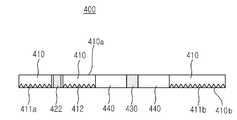
도 5a는 본 발명의 제3 실시 예에 따른 광센서 모듈을 도시한 도면이고, 도 5b는 도 5a에 A~B를 절개한 단면을 도시한 도면이다. 도 5a 및 도 5b를 참조하면, 본 실시 예에 따른 광센서 모듈(410)은 대상 신체 부위에 접하는 제1 면(410a)과 상기 제1 면(410a)의 반대 편에 위치된 제2 면(410b)을 구비한 도파로(410)와, 상기 도파로(410)의 제1 면(410a)에 수광부가 노출되도록 삽입되며 대상 신체 부위에 서 반사된 광의 세기를 검출해내기 위한 광검출기(430)와, 제1 및 제2 광원(421,422)과, 상기 광검출기(430)의 둘레를 둘러싸는 차단층(440)을 포함한다.FIG. 5A is a view illustrating an optical sensor module according to a third embodiment of the present invention, and FIG. 5B is a cross-sectional view taken along line A to B of FIG. 5A. 5A and 5B, the
상기 제1 광원(421)은 통상 체지방 등의 생체 신호 측정을 위한 제1 광을 생성하고, 상기 제2 광원(422)은 맥파 측정을 위한 제2 광을 생성한다. 상기 제1 및 제2 광원(421,422)은 동일 파장 대역의 광을 생성할 수 있는 광원들이 사용될 수 있으며, 상기 광검출기(430)는 대상 신체 부위에서 반사된 직류 파형의 제1 광으로부터 체지방 등의 생체 신호를 검출해내고, 대상 신체 부위에서 반사된 제2 광의 교류 파형 변화로부터 맥파 등의 생체 신호를 검출해낼 수 있다. 상기 제2 광원(422)은 신호 대 잡음비가 최대가 될 수 있는 곳에 위치시킨다. 상기 제2 광원(422)은 맥파 등을 측정하기 위해서 상기 제1 광원(421)보다 상기 광검출기(430)에 인접하게 위치되는 것이 바람직하다.The first
맥파 등의 생체 신호는 맥박, 스트레스, 호흡수, 혈중산소 포화도 등의 산출에 사용되며, 상기 제2 광원(422)은 상기 제1 광원(421)과 확산 패턴들(411a,411b,412)에 의해 형성되는 링 형태의 발광부의 크기가 손가락 등에서 측정에 적합하지 않을 경우에도 상기 광검출기(430)에 인접하게 위치되므로 측정이 가능하다. 맥파의 측정은 심장의 수축, 이완에 따른 혈류량 변화와 혈관 내 헤모글로빈 양의 주기적인 변화로부터 유발된 제2 광의 세기를 감시함으로써 측정될 수 있다.Biological signals such as pulse waves are used to calculate pulse, stress, respiratory rate, blood oxygen saturation, and the like. The second
기존의 반사형 생체 신호 측정 센서는 단순히 광원과 수광부가 동일 평면 상에 일렬로 배열된 형태이므로 대상 신체의 미세한 움직임에 의한 잡음 유발 및 그 로 인한 오류 등의 문제점이 있다. 반면에, 본 발명에 따른 광센서 모듈은 광검출기 주위의 모든 방향에서 광이 입사되므로 미세한 움직임에 의한 잡음의 영향을 최소화시킬 수 있다.In the conventional reflective biosignal measuring sensor, since the light source and the light receiving unit are simply arranged in a line on the same plane, there is a problem such as noise caused by minute movement of the target body and an error thereof. On the other hand, in the optical sensor module according to the present invention, since light is incident in all directions around the photodetector, it is possible to minimize the influence of noise caused by fine movement.
상기 광검출기(430)는 상기 도파로(410)의 중심부에 수광면이 노출되도록 삽입되며, 상기 차단층(440)은 상기 광검출기(430)와 상기 도파로(410)의 사이에 상기 광검출기(430)의 둘레를 둘러싸도록 위치된다. 상기 차단층(440)은 상기 도파로(410)를 통해서 상기 광검출기(430)로 직접 입사되는 제1 및 제2 광을 차단한다. 상기 광검출기(430)는 상기 도파로(410)의 제1 면(410a)에 노출된 수광면을 통해서 생체 신호 측정의 대상인 신체 부위에서 반사된 제1 및 제2 광을 수광한다.The
상기 도파로(410)는 그 중심부에 상기 광검출기(430) 및 상기 광검출기(430)를 둘러싸는 차단층(440)이 삽입되며, 상기 제2 면(410b)에는 상기 제1 및 제2 면 (410a,410b) 사이의 측면에 위치된 광원에서 생성된 광을 균일한 세기로 대상 신체 부위로 반사시키기 위한 확산 패턴들(411a,411b,412)이 형성된다.The
도 6a는 본 발명의 제4 실시 예에 따른 광센서 모듈을 도시한 도면이고, 도 6b는 도 6a에 도시된 A'~B'을 절개한 단면을 도시한 도면이다. 도 6a 및 도 6b를 참조하면, 본 실시 예에 따른 광센서 모듈(500)은 제 및 제2 도파로(510,542), 광검출기(530)와, 각각 둘 이상의 제1 및 제2 광원들(521a,521b,522a,522b)과, 상기 광검출기(530)의 둘레를 둘러싸는 차단층(541)을 포함한다.FIG. 6A is a view illustrating an optical sensor module according to a fourth embodiment of the present invention, and FIG. 6B is a cross-sectional view taken along the line A ′ to B ′ of FIG. 6A. 6A and 6B, the
상기 제1 광원들(521a,521b)은 체지방 등의 생체 신호를 측정하기 위한 제1 광을 생성하며, 상기 광검출기(530)를 중심으로 상기 제1 도파로(510)의 측면에 상 호 대칭되게 위치된다. 상기 제2 광원들(522a,522b)은 맥파 등의 생체 신호를 측정하기 위한 제2 광을 생성하며, 상기 광검출기(530)를 중심으로 상기 제1 도파로(510)의 일 부분에 삽입된다. 상기 제2 광원들(522a,522b)은 상기 광검출기(530)로부터 이격된 간격이 상기 제1 광원들(521a,521b)이 상기 광검출기(530)로부터 이격된 간격보다 짧게 위치된다. 상기 각 제1 및 제2 광원(521,521b,522a,522b)은 600㎚ 이상 파장의 광을 생성할 수 있는 발광 다이오드 또는 측면 발광 다이오드 등이 사용될 수 있다.The
상기 제1 도파로(510)는 상기 제2 도파로(542)의 둘레를 둘러싸며, 상기 제 광을 제2 면(510b)에 위치된 확산 패턴(511)에서 제1 면 측으로 균일한 세기로 출력될 수 있도록 반사시킨다. 상기 제2 도파로(542)는 측면에 상기 제2 광원들(522a,522b)이 위치되며, 상기 제2 광을 확산 패턴(543)에서 균일한 세기로 확산시킨 후 대상 신체 부위로 출력한다. 상기 제2 도파로(542)의 중심에는 상기 광검출기(530)가 수광면이 노출되게 삽입되며, 상기 광검출기(530)의 둘레에는 차단층(541)이 삽입된다.The
본 발명은 도파로를 이용해서 광을 도파시킴으로써 균일한 측정 대상의 신체 부위에 균일한 세기의 광을 조사할 수 있다. 따라서, 균일한 세기의 광을 조사하기 위해서 대상 신체 부위의 접촉면보다 접촉면에 수직한 길이 방향으로 긴 구조의 광센서 모듈을 작은 부피의 광센서 모듈로 대체할 수 있는 이점이 있다.According to the present invention, light of a uniform intensity can be irradiated to a body part of a uniform measurement object by guiding light using a waveguide. Therefore, in order to irradiate light of uniform intensity, there is an advantage in that the optical sensor module having a structure that is longer in the longitudinal direction perpendicular to the contact surface than the contact surface of the target body part can be replaced with a small volume optical sensor module.
또한, 본 발명은 측정 대상 신체 부위에 균일한 세기의 광을 조사할 수 있게되므로 측정의 재현성이 향상되고, 동일한 파장의 광원을 이용해서 체지방 맥파, 맥박, 심박 변이도(HRV, Heart Rate Variability)를 이용한 스트레스 등과 같이 다양한 생체 신호 측정이 가능해지는 이점이 있다.In addition, the present invention improves the reproducibility of the measurement by irradiating light of uniform intensity to the body part to be measured, and the body fat pulse wave, pulse rate, and heart rate variability (HRV) using the light source of the same wavelength. There is an advantage in that it is possible to measure a variety of bio-signals, such as used stress.
그 외에도, 본 발명은 생체 신호 측정의 정확도의 향상 및 추가적인 기능(혈중 산소 농도 -SpO2- 등)을 부과가 용이하다. 즉, 본 발명은 필요에 따라서 도파로의 둘레 또는 밑면에 추가적인 발광 다이오드를 설치하거나, 복수 파장의 광들을 생성할 수 있는 복수의 발광 다이오드 들이 단일 패키지로 구성된 단일 광원을 사용함으로써 추가적인 기능을 수행할 수 있고, 그에 따른 센서의 부피 증가도 최소화시킬 수 있는 이점이 있다.In addition, the present invention makes it easy to improve the accuracy of the biosignal measurement and to impose additional functions (such as blood oxygen concentration-SpO 2-). That is, the present invention can perform additional functions by installing an additional light emitting diode around or below the waveguide as needed, or by using a single light source in which a plurality of light emitting diodes capable of generating light of a plurality of wavelengths is configured in a single package. And, there is an advantage that can minimize the increase in volume of the sensor accordingly.
Claims (20)
Translated fromKoreanPriority Applications (2)
| Application Number | Priority Date | Filing Date | Title |
|---|---|---|---|
| KR1020060022231AKR100770833B1 (en) | 2006-03-09 | 2006-03-09 | Optical sensor module |
| US11/714,978US20070210242A1 (en) | 2006-03-09 | 2007-03-07 | Optical sensor module |
Applications Claiming Priority (1)
| Application Number | Priority Date | Filing Date | Title |
|---|---|---|---|
| KR1020060022231AKR100770833B1 (en) | 2006-03-09 | 2006-03-09 | Optical sensor module |
Publications (2)
| Publication Number | Publication Date |
|---|---|
| KR20070092869A KR20070092869A (en) | 2007-09-14 |
| KR100770833B1true KR100770833B1 (en) | 2007-10-26 |
Family
ID=38477981
Family Applications (1)
| Application Number | Title | Priority Date | Filing Date |
|---|---|---|---|
| KR1020060022231AActiveKR100770833B1 (en) | 2006-03-09 | 2006-03-09 | Optical sensor module |
Country Status (2)
| Country | Link |
|---|---|
| US (1) | US20070210242A1 (en) |
| KR (1) | KR100770833B1 (en) |
Families Citing this family (16)
| Publication number | Priority date | Publication date | Assignee | Title |
|---|---|---|---|---|
| KR100827138B1 (en) | 2006-08-10 | 2008-05-02 | 삼성전자주식회사 | Biometric information measuring device |
| KR101414927B1 (en) | 2007-08-27 | 2014-07-07 | 삼성전자주식회사 | Sensor for measuring bio-information and earphone equipped with same |
| DE102008013525B4 (en) | 2008-03-08 | 2010-07-29 | Nordischer Maschinenbau Rud. Baader Gmbh + Co Kg | Apparatus and method for contactless identification of characteristics of continuously conveyed, translucent products |
| US20100004518A1 (en) | 2008-07-03 | 2010-01-07 | Masimo Laboratories, Inc. | Heat sink for noninvasive medical sensor |
| US8515509B2 (en) | 2008-08-04 | 2013-08-20 | Cercacor Laboratories, Inc. | Multi-stream emitter for noninvasive measurement of blood constituents |
| KR101050644B1 (en) | 2008-12-15 | 2011-07-19 | 삼성전자주식회사 | Biometric information measuring device and earphone with same |
| KR20110073756A (en)* | 2009-12-24 | 2011-06-30 | 삼성전자주식회사 | Condition information tagging method and multimedia device using same |
| KR101150860B1 (en)* | 2010-08-06 | 2012-07-19 | 한국광기술원 | Pulse Generator Using Light Sensor |
| JP5619050B2 (en)* | 2012-02-29 | 2014-11-05 | 日本電信電話株式会社 | Biological information detection device |
| FR2995419B1 (en) | 2012-09-12 | 2015-12-11 | Commissariat Energie Atomique | CONTACTLESS USER INTERFACE SYSTEM |
| FR2996933B1 (en)* | 2012-10-15 | 2016-01-01 | Isorg | PORTABLE SCREEN DISPLAY APPARATUS AND USER INTERFACE DEVICE |
| US20150164352A1 (en)* | 2013-12-18 | 2015-06-18 | Lg Electronics Inc. | Apparatus for measuring bio-information and a method for error compensation thereof |
| KR102649561B1 (en)* | 2016-06-30 | 2024-03-19 | 삼성전자주식회사 | Non-Invasive Biometric Sensor Based on Organic Photodetector |
| KR102500766B1 (en)* | 2017-12-29 | 2023-02-17 | 삼성전자주식회사 | Apparatus for measuring biological signal and operating method thereof |
| WO2023085404A1 (en)* | 2021-11-12 | 2023-05-19 | 株式会社ジャパンディスプレイ | Detection device |
| JP7745002B2 (en)* | 2021-11-12 | 2025-09-26 | 株式会社Magnolia White | Detection device |
Citations (4)
| Publication number | Priority date | Publication date | Assignee | Title |
|---|---|---|---|---|
| JPH0293311A (en)* | 1988-09-30 | 1990-04-04 | Ricoh Co Ltd | Parallel position detection device |
| US5071248A (en)* | 1985-05-29 | 1991-12-10 | Asi Ag | Optical sensor for selective detection of substances and/or for the detection of refractive index changes in gaseous, liquid, solid and porous samples |
| US6045756A (en)* | 1996-10-01 | 2000-04-04 | Texas Instruments Incorporated | Miniaturized integrated sensor platform |
| JP2003156432A (en)* | 2001-11-22 | 2003-05-30 | Toshiba Corp | Optical waveguide type biochemical sensor |
Family Cites Families (6)
| Publication number | Priority date | Publication date | Assignee | Title |
|---|---|---|---|---|
| US4633087A (en)* | 1985-04-24 | 1986-12-30 | Trebor Industries, Inc. | Near infrared apparatus for measurement of organic constituents of material |
| US4850365A (en)* | 1988-03-14 | 1989-07-25 | Futrex, Inc. | Near infrared apparatus and method for determining percent fat in a body |
| US5103085A (en)* | 1990-09-05 | 1992-04-07 | Zimmerman Thomas G | Photoelectric proximity detector and switch |
| US7890158B2 (en)* | 2001-06-05 | 2011-02-15 | Lumidigm, Inc. | Apparatus and method of biometric determination using specialized optical spectroscopy systems |
| US6134458A (en)* | 1998-12-15 | 2000-10-17 | Futrex Inc. | Light probe for a near-infrared body chemistry measurement instrument |
| CH696516A5 (en)* | 2003-05-21 | 2007-07-31 | Asulab Sa | Portable instrument for measuring a physiological quantity comprising a device for illuminating the surface of an organic tissue. |
- 2006
- 2006-03-09KRKR1020060022231Apatent/KR100770833B1/enactiveActive
- 2007
- 2007-03-07USUS11/714,978patent/US20070210242A1/ennot_activeAbandoned
Patent Citations (4)
| Publication number | Priority date | Publication date | Assignee | Title |
|---|---|---|---|---|
| US5071248A (en)* | 1985-05-29 | 1991-12-10 | Asi Ag | Optical sensor for selective detection of substances and/or for the detection of refractive index changes in gaseous, liquid, solid and porous samples |
| JPH0293311A (en)* | 1988-09-30 | 1990-04-04 | Ricoh Co Ltd | Parallel position detection device |
| US6045756A (en)* | 1996-10-01 | 2000-04-04 | Texas Instruments Incorporated | Miniaturized integrated sensor platform |
| JP2003156432A (en)* | 2001-11-22 | 2003-05-30 | Toshiba Corp | Optical waveguide type biochemical sensor |
Also Published As
| Publication number | Publication date |
|---|---|
| KR20070092869A (en) | 2007-09-14 |
| US20070210242A1 (en) | 2007-09-13 |
Similar Documents
| Publication | Publication Date | Title |
|---|---|---|
| KR100770833B1 (en) | Optical sensor module | |
| KR100827138B1 (en) | Biometric information measuring device | |
| KR100905571B1 (en) | Biometric information measuring device | |
| JP4701468B2 (en) | Biological information measuring device | |
| EP3413791B1 (en) | Methods and devices for calculating blood pressure based on measurements of arterial blood flow and arterial lumen | |
| CN112955075B (en) | Device and method for analyzing a substance | |
| TWI429418B (en) | Optical vital sign detection method and measurement device | |
| CN100479751C (en) | Portable instrument for measuring physiological parameter | |
| CA2221968C (en) | Sensor, method and device for optical blood oximetry | |
| JP6880024B2 (en) | Equipment and methods for analyzing substances | |
| US20110004106A1 (en) | Optical biological information detecting apparatus and optical biological information detecting method | |
| CN109069011B (en) | Optical measuring device for cardiovascular diagnosis | |
| WO2003063704A1 (en) | Optical biological information measuring method and optical biological information measuring instrument | |
| WO2016103648A1 (en) | Sensor, sensor device, and sensor system | |
| US20150208924A1 (en) | Photoacoustic sensors with diffusing elements for patient monitoring | |
| CN110087544A (en) | Biological substance measuring device and biological substance measuring method | |
| KR20190048706A (en) | Glucose measuring device | |
| JP4170262B2 (en) | Biological information measuring device and standard element | |
| JP2009106373A (en) | Sensing device for biological surface tissue | |
| KR102223689B1 (en) | Apparatus for measuring bio-information | |
| GB2311366A (en) | Determining absorption coefficients or modified scattering ceofficients | |
| US20150265154A1 (en) | Systems and methods for a multi-element medical sensor | |
| Matsushita et al. | Fundamental study of reflection pulse oximetry | |
| JP7498935B2 (en) | Optical Sensor | |
| JP2011135986A (en) | Biological light measuring probe and biological light measuring device |
Legal Events
| Date | Code | Title | Description |
|---|---|---|---|
| A201 | Request for examination | ||
| PA0109 | Patent application | Patent event code:PA01091R01D Comment text:Patent Application Patent event date:20060309 | |
| PA0201 | Request for examination | ||
| E902 | Notification of reason for refusal | ||
| PE0902 | Notice of grounds for rejection | Comment text:Notification of reason for refusal Patent event date:20070430 Patent event code:PE09021S01D | |
| E701 | Decision to grant or registration of patent right | ||
| PE0701 | Decision of registration | Patent event code:PE07011S01D Comment text:Decision to Grant Registration Patent event date:20070904 | |
| PG1501 | Laying open of application | ||
| GRNT | Written decision to grant | ||
| PR0701 | Registration of establishment | Comment text:Registration of Establishment Patent event date:20071022 Patent event code:PR07011E01D | |
| PR1002 | Payment of registration fee | Payment date:20071022 End annual number:3 Start annual number:1 | |
| PG1601 | Publication of registration | ||
| PR1001 | Payment of annual fee | Payment date:20100929 Start annual number:4 End annual number:4 | |
| PR1001 | Payment of annual fee | Payment date:20110929 Start annual number:5 End annual number:5 | |
| FPAY | Annual fee payment | Payment date:20120927 Year of fee payment:6 | |
| PR1001 | Payment of annual fee | Payment date:20120927 Start annual number:6 End annual number:6 | |
| FPAY | Annual fee payment | Payment date:20130927 Year of fee payment:7 | |
| PR1001 | Payment of annual fee | Payment date:20130927 Start annual number:7 End annual number:7 | |
| FPAY | Annual fee payment | Payment date:20140929 Year of fee payment:8 | |
| PR1001 | Payment of annual fee | Payment date:20140929 Start annual number:8 End annual number:8 | |
| FPAY | Annual fee payment | Payment date:20150925 Year of fee payment:9 | |
| PR1001 | Payment of annual fee | Payment date:20150925 Start annual number:9 End annual number:9 | |
| FPAY | Annual fee payment | Payment date:20170927 Year of fee payment:11 | |
| PR1001 | Payment of annual fee | Payment date:20170927 Start annual number:11 End annual number:11 | |
| FPAY | Annual fee payment | Payment date:20190415 Year of fee payment:12 | |
| PR1001 | Payment of annual fee | Payment date:20190415 Start annual number:12 End annual number:12 | |
| FPAY | Annual fee payment | Payment date:20191017 Year of fee payment:13 | |
| PR1001 | Payment of annual fee | Payment date:20191017 Start annual number:13 End annual number:13 | |
| PR1001 | Payment of annual fee | Payment date:20201019 Start annual number:14 End annual number:14 | |
| PR1001 | Payment of annual fee | Payment date:20221024 Start annual number:16 End annual number:16 | |
| PR1001 | Payment of annual fee | Payment date:20231023 Start annual number:17 End annual number:17 | |
| PR1001 | Payment of annual fee | Payment date:20241102 Start annual number:18 End annual number:18 |