KR100770641B1 - Indirect heating cooking device - Google Patents
Indirect heating cooking deviceDownload PDFInfo
- Publication number
- KR100770641B1 KR100770641B1KR1020060047398AKR20060047398AKR100770641B1KR 100770641 B1KR100770641 B1KR 100770641B1KR 1020060047398 AKR1020060047398 AKR 1020060047398AKR 20060047398 AKR20060047398 AKR 20060047398AKR 100770641 B1KR100770641 B1KR 100770641B1
- Authority
- KR
- South Korea
- Prior art keywords
- cooking apparatus
- coupling
- circuit
- heater
- control circuit
- Prior art date
- Legal status (The legal status is an assumption and is not a legal conclusion. Google has not performed a legal analysis and makes no representation as to the accuracy of the status listed.)
- Expired - Fee Related
Links
Images


Classifications
- A—HUMAN NECESSITIES
- A47—FURNITURE; DOMESTIC ARTICLES OR APPLIANCES; COFFEE MILLS; SPICE MILLS; SUCTION CLEANERS IN GENERAL
- A47J—KITCHEN EQUIPMENT; COFFEE MILLS; SPICE MILLS; APPARATUS FOR MAKING BEVERAGES
- A47J31/00—Apparatus for making beverages
- A47J31/42—Beverage-making apparatus with incorporated grinding or roasting means for coffee
- A—HUMAN NECESSITIES
- A47—FURNITURE; DOMESTIC ARTICLES OR APPLIANCES; COFFEE MILLS; SPICE MILLS; SUCTION CLEANERS IN GENERAL
- A47J—KITCHEN EQUIPMENT; COFFEE MILLS; SPICE MILLS; APPARATUS FOR MAKING BEVERAGES
- A47J43/00—Implements for preparing or holding food, not provided for in other groups of this subclass
- A47J43/04—Machines for domestic use not covered elsewhere, e.g. for grinding, mixing, stirring, kneading, emulsifying, whipping or beating foodstuffs, e.g. power-driven
- A47J43/07—Parts or details, e.g. mixing tools, whipping tools
- A47J43/0716—Parts or details, e.g. mixing tools, whipping tools for machines with tools driven from the lower side
- A—HUMAN NECESSITIES
- A47—FURNITURE; DOMESTIC ARTICLES OR APPLIANCES; COFFEE MILLS; SPICE MILLS; SUCTION CLEANERS IN GENERAL
- A47J—KITCHEN EQUIPMENT; COFFEE MILLS; SPICE MILLS; APPARATUS FOR MAKING BEVERAGES
- A47J27/00—Cooking-vessels
- A47J27/004—Cooking-vessels with integral electrical heating means
- A—HUMAN NECESSITIES
- A47—FURNITURE; DOMESTIC ARTICLES OR APPLIANCES; COFFEE MILLS; SPICE MILLS; SUCTION CLEANERS IN GENERAL
- A47J—KITCHEN EQUIPMENT; COFFEE MILLS; SPICE MILLS; APPARATUS FOR MAKING BEVERAGES
- A47J31/00—Apparatus for making beverages
- A—HUMAN NECESSITIES
- A47—FURNITURE; DOMESTIC ARTICLES OR APPLIANCES; COFFEE MILLS; SPICE MILLS; SUCTION CLEANERS IN GENERAL
- A47J—KITCHEN EQUIPMENT; COFFEE MILLS; SPICE MILLS; APPARATUS FOR MAKING BEVERAGES
- A47J31/00—Apparatus for making beverages
- A47J31/40—Beverage-making apparatus with dispensing means for adding a measured quantity of ingredients, e.g. coffee, water, sugar, cocoa, milk, tea
- A—HUMAN NECESSITIES
- A47—FURNITURE; DOMESTIC ARTICLES OR APPLIANCES; COFFEE MILLS; SPICE MILLS; SUCTION CLEANERS IN GENERAL
- A47J—KITCHEN EQUIPMENT; COFFEE MILLS; SPICE MILLS; APPARATUS FOR MAKING BEVERAGES
- A47J36/00—Parts, details or accessories of cooking-vessels
- A47J36/24—Warming devices
- A47J36/2444—Drinking cups with heating means
- A47J36/2461—Drinking cups with heating means with electrical heating means
- A47J36/2466—Drinking cups with heating means with electrical heating means with integral heating means
- A47J36/2472—Drinking cups with heating means with electrical heating means with integral heating means of the cordless type, i.e. whereby the cup can be plugged into an electrically-powered base element
Landscapes
- Engineering & Computer Science (AREA)
- Food Science & Technology (AREA)
- Mechanical Engineering (AREA)
- Food-Manufacturing Devices (AREA)
- Electric Stoves And Ranges (AREA)
- Baking, Grill, Roasting (AREA)
Abstract
Translated fromKoreanDescription
Translated fromKorean도 1은 본 발명에 따른 조리 장치의 분해 사시도를 도시한 것이다.1 shows an exploded perspective view of a cooking apparatus according to the present invention.
도 2는 본 발명에 따른 조리기의 내부를 나타내기 위한 단면도를 도시한 것이다.Figure 2 shows a cross-sectional view for showing the inside of the cooker according to the present invention.
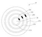
도 3은 본 발명에 따른 히터의 실시 예를 도시한 것이다.3 illustrates an embodiment of a heater according to the present invention.
도 4는 본 발명에 따른 조리 장치에 설치될 수 있는 감지 제어 회로를 도시한 것이다.4 illustrates a sensing control circuit that can be installed in a cooking apparatus according to the present invention.
본 발명은 간접 가열 방식의 자동 조리 장치에 관한 것이고, 구체적으로 수용 면의 밑면 외부에 설치된 원판 형태의 히터, 히터의 아래쪽에 설치된 모터 및 감지 제어 회로를 가진 자동 조리 장치에 관한 것이다.The present invention relates to an automatic cooking apparatus of an indirect heating method, and more particularly to an automatic cooking apparatus having a disk-shaped heater installed outside the bottom of the receiving surface, a motor provided below the heater, and a sensing control circuit.
자동으로 음식을 조리할 수 있는 다양한 장치들이 개발되어 왔다. 커피를 만드는 장치, 과일 또는 채소의 믹서 장치, 두유 또는 두부 제조기, 또는 죽 제조기와 같은 장치들은 가정에서 편리하게 사용될 수 있도록 소형화 및 자동화가 된 형태로 만들어진다. 이러한 장치 중에서 특히 두유 또는 두부 제조기는 조리 과정에 서 분쇄 공정 및 가열 공정이 동시에 요구되기 때문에 다양한 구성 요소를 필요로 한다. 이와 같은 구성 요소들이 적절하게 배치되어 사용자가 조리 장치를 편리하고 안전하게 사용할 수 있어야 한다.Various devices have been developed for automatically cooking food. Devices such as coffee making machines, fruit or vegetable mixers, soy milk or tofu makers, or porridge makers are made in a compact and automated form for convenient use at home. Of these devices, in particular soymilk or tofu makers require a variety of components because the grinding process and the heating process are required simultaneously in the cooking process. Such components should be properly arranged so that the user can use the cooking device conveniently and safely.
자동으로 두부 또는 두유를 제조할 수 있는 다양한 형태의 장치가 이 분야에 공지되어 있다. 특허출원번호 제10-2003-0068301호 “가정용 죽 제조기 및 이를 이용한 죽 제조방법”은 모터 및 제어 회로를 포함하는 구동부가 상부에 위치하고 그리고 용기부가 아래쪽에서 구동부와 분리 가능하도록 결합이 되는 죽 제조기를 개시한다.Various types of devices are known in the art that can produce tofu or soy milk automatically. Patent application No. 10-2003-0068301 "Household porridge maker and a method of manufacturing porridge using the same" is a porridge maker in which the drive unit including the motor and the control circuit is located on the upper side and the container unit is detachably coupled to the drive unit at the bottom. It starts.
가정용 두부 제조기의 구성 관계를 살펴보면, 모터는 제조기의 위쪽에 또는 아래쪽에 설치될 수 있다. 구동부가 위쪽에 설치되는 되는 경우 두부 제조기의 안정성이 낮아지고 그리고 취급이 불편하다는 단점을 가지는 반면 누수 문제가 용이하게 해결된다는 장점을 가진다. 이에 비하여 구동부가 아래쪽에 설치되는 경우 안정성 및 취급성의 문제가 해결되는 반면 누수 방지를 위한 제조비용이 증가한다는 단점을 가진다.Looking at the configuration of the home tofu maker, the motor may be installed above or below the maker. When the driving unit is installed on the upper side, the stability of the head maker is lowered and the handling is inconvenient, while the leakage problem is easily solved. On the other hand, when the driving unit is installed at the bottom, the problem of stability and handleability is solved, but the manufacturing cost for preventing leakage has a disadvantage.
특허출원번호 제10-2004-0115661호 “분쇄 및 가열 기능을 갖는 식품 가공기 및 이를 이용한 식품 가공 방법”은 모터가 아래쪽에 설치된 두부 제조기를 개시한다. 상기 문헌에서 개시된 발명은 모터를 포함하는 구동부를 아래쪽에 설치하여 조리장치 자체의 안정성을 향상시켰지만 다른 한편으로 가열 및 제어의 효율성이 낮고 아울러 여전히 취급이 불편하다는 단점을 가진다.Patent application No. 10-2004-0115661 "food processing machine having a grinding and heating function and a food processing method using the same" discloses a tofu maker with a motor installed on the bottom. The invention disclosed in this document improves the stability of the cooking apparatus itself by installing a drive unit including a motor on the lower side, but on the other hand has a disadvantage of low heating and control efficiency and still inconvenient handling.
구동부가 아래쪽에 위치함으로서 발생할 수 있는 누수 문제는 밀봉 기술의 발달에 따라 해결이 가능한 기술적 문제가 되었다.Leakage problems that may occur as the drive unit is positioned below become a technical problem that can be solved with the development of sealing technology.
간접 가열 방식의 조리 장치는 직접 가열 방식에 비하여 조리 음식의 균일한 가열이 가능하다는 이점을 가지지만, 열이 중간 매체를 통하여 전달되어야하므로 열효율이 낮아진다는 문제점을 가진다. 아울러 열이 필요한 부분뿐만 아니라 다른 장치에도 전달이 될 수 있다는 문제점을 가진다. 그러므로 이러한 문제를 해결할 수 있는 간접 가열 방식의 조리기가 요구된다.The indirect heating type cooking apparatus has the advantage of uniform heating of the cooked food as compared to the direct heating type, but has a problem that the heat efficiency is lowered because heat must be transferred through the intermediate medium. In addition, there is a problem that can be transferred to other devices as well as the heat needs. Therefore, there is a need for an indirect heating cooker that can solve this problem.
조리 장치와 관련된 또 다른 문제점은 과일 음료, 두부, 두유, 커피 제조 또는 약재 가열을 위하여 각각의 장치가 사용되어야 한다는 점이다. 전체 조리 과정이 일련의 연속된 작동 과정을 통하여 자동으로 이루어져야 하고 동시에 여러 가지 필요한 음식들이 하나의 장치를 사용하여 만들어질 수 있다면 여러 가지 이점이 발생할 수 있다. 그러므로 다양한 음식을 제조할 수 있는 복합 조리 장치가 필요하다. 또한 조리 장치들은 대부분이 가정에서 사용되므로 안정성을 가져야 한다. 특히 장치는 전기 장치를 통하여 가열이 되므로 전기적 안정성이 중요한 요소가 될 수 있다.Another problem associated with cooking devices is that each device must be used for fruit drinks, tofu, soy milk, coffee making or for medicinal heating. If the entire cooking process has to be done automatically through a series of continuous operations and at the same time several necessary foods can be made using a single device, several advantages can arise. Therefore, there is a need for a complex cooking device capable of producing a variety of food. In addition, most cooking devices are used at home, so they must be stable. In particular, since the device is heated through the electric device, electrical stability may be an important factor.
본 발명은 제시된 문제를 해결하기 위하여 효율적으로 열전달이 이루어지고 그리고 전기적 안전 수단을 가진 다양한 음식을 조리할 수 있는 간접 가열 방식의 복합 조리 장치를 제안한다.The present invention proposes a complex cooking apparatus of an indirect heating method that can efficiently heat the various foods with an electric safety means in order to solve the problems presented.
본 발명의 목적은 판 히터 및 감지 제어 회로를 가진 간접 가열 방식의 복합 조리 장치를 제공하는 것이다.It is an object of the present invention to provide an indirect heating composite cooking apparatus having a plate heater and a sensing control circuit.
본 발명의 적절한 실시 형태에 따르면, 분리 가능한 분쇄 칼날을 수용하고 측면에 스크린이 형성된 분리 가능한 분리 통, 결합 접점을 가지는 손잡이 및 감지 센서 및 발열량의 조절이 가능하고 다수 개의 열 밴드가 형성된 판 형태의 히터를 가지는 결합 하우징; 모터 및 제어 장치를 내장하고 결합 하우징의 아래쪽 부분과 결합하는 베이스; 손잡이와 결합되고 그리고 결합 접점과 접촉되는 전기 접점을 가지는 결합 홈 및 안전장치를 가지는 결합 부분; 및 두 개의 전극으로부터 발생하는 전기적 신호를 입력받는 입력 회로, 입력 회로의 전기적 신호를 처리하여 출력 회로를 통하여 출력 회로에 연결된 전기적 장치의 작동을 제어하는 제어 회로 및 제어 회로의 작동 상태를 탐지하는 안전회로를 가지는 감지 제어 회로를 포함한다.According to a preferred embodiment of the present invention, there is provided a detachable separating barrel having a detachable grinding blade and having a screen on the side thereof, a handle having a coupling contact and a sensing sensor, and a plate type in which a plurality of heat bands are formed and the heat generation is adjustable. A coupling housing having a heater; A base that incorporates a motor and a control device and engages with a lower portion of the coupling housing; A coupling portion having a coupling groove and a safety device coupled to the handle and having electrical contacts in contact with the coupling contact; And an input circuit for receiving electrical signals generated from two electrodes, a control circuit for processing an electrical signal of the input circuit, and controlling an operation of an electrical device connected to the output circuit through the output circuit, and detecting an operation state of the control circuit. And a sense control circuit having a circuit.
아래에서 본 발명은 도면에 첨부된 실시 예를 이용하여 상세하게 설명이 된다.Hereinafter, the present invention will be described in detail using the embodiments attached to the drawings.
도 1은 본 발명에 따른 조리 장치(1)의 분해 사시도를 도시한 것이다.1 shows an exploded perspective view of a cooking apparatus 1 according to the invention.
도 1을 참조하면, 조리 장치(1)는 외형을 형성하는 고정 하우징(H1) 및 고정 하우징(H1)과 결합하는 결합 하우징(H2)을 포함한다. 고정 하우징(H1)은 원통형으로 형성될 수 있고 그리고 고정 하우징(H1)을 유지하기 위한 베이스(11) 및 고정 하우징(H1)의 분리 결합을 위한 결합 부분(12)을 가진다. 고정 하우징(H1)은 한쪽 측면이 개방된 원통형 그리고 결합 하우징(H2)은 고정 하우징(H1)에 결합될 수 있는 원통형이 될 수 있다. 고정 하우징(H1) 및 결합 하우징(H2)의 결합을 위하여 베이스(11)의 위쪽에 결합 테(111) 그리고 결합 부분(12)의 개방된 측면의 한쪽 벽면에 결합 홈(121)이 각각 형성된다. 결합 테(111)의 베이스(11)의 위쪽 가장 자리를 따라 결합 하우징(H2)의 아래쪽 부분을 수용할 수 있도록 형성된다. 결합 하우징(H2)은 결합 테(111)의 내부에서 회전 가능하도록 결합이 되고 그리고 결합 하우징(H2)의 측면에 형성된 손잡이(13)는 결합 부분(12)의 결합 홈(121)에 결합이 된다. 결합 홈(121)의 안쪽 면과 손잡이(13)의 측면이 충분히 밀착이 되면 결합 하우징(H2)은 고정 하우징(H1)에 고정이 된다. 손잡이(13)가 결합 홈(121)에 안정된 상태로 결합 고정이 되면 손잡이(13)의 측면에 형성된 결합 접점(도시되지 않음) 및 결합 홈(121)의 안쪽 면에 형성된 전기 접점(122)이 접촉하게 되어 필요한 전원 공급이 이루어질 수 있다. 필요에 따라 손잡이(13)의 위쪽 면에는 신축성 소재로 만들어진 결합 돌기(131)가 형성되고 그리고 결합 홈(121)의 위쪽 면에는 대응 홈(도시되지 않음)이 형성될 수 있다. 결합 돌기(131) 및 결합 홈은 고정 하우징(H1) 및 결합 하우징(H2)의 고정 위치를 결정하고 그리고 안정된 결합이 유지되도록 한다. 고정 하우징(H1)의 결합 부분(12)의 반대편 면에 조리기에서 조리되는 식품 또는 조리 진행 상태를 시각적으로 보여주기 위한 LCD 창(123) 및 선택 버튼(124)이 형성될 수 있다. LCD 창(123) 및 선택 버튼(124)은 임의의 위치에 적절하게 설치될 수 있다.Referring to FIG. 1, the cooking apparatus 1 includes a fixed housing H1 forming an outer shape and a coupling housing H2 engaged with the fixed housing H1. The fixed housing H1 can be formed in a cylindrical shape and has a
고정 하우징(H1) 및 결합 하우징(H2)은 단열 소재로 만들어 질 수 있고 그리고 내부 및 외부 사이의 열 출입을 차단하기 위하여 이중벽으로 형성될 수 있다.The fixed housing H1 and the coupling housing H2 can be made of an insulating material and can be formed with double walls to block heat entry between the inside and the outside.
도 2는 본 발명에 따른 조리기의 내부를 나타내기 위한 단면도를 도시한 것이다.Figure 2 shows a cross-sectional view for showing the inside of the cooker according to the present invention.
도 2를 참조하면, 고정 하우징(H1)은 베이스(11)의 내부에 설치된 제어 장치(21) 및 모터(22)를 포함한다. 제어 장치(21)는 선택 버튼(124)에서 입력된 내용에 따라 조리가 적절하게 이루어지도록 각각의 구성 요소의 작동을 제어한다. 그리고 모터(22)는 제어 장치(21)의 지시에 따라 조리 재료를 분쇄할 수 있는 회전력을 전달한다. 고정 하우징(H1)은 또한 안전장치(23)를 포함할 수 있다. 안전장치(23)는 결합 하우징(H2)의 손잡이(13)의 아래쪽 면과 접촉하는 베이스(11)의 면의 아래쪽에 설치된다. 도 2에 도시된 것처럼, 안전장치(23)는 베이스(11) 면의 위쪽으로 돌출하는 돌기(231)를 포함한다. 돌기(231)는 스프링과 같은 탄성체로 유지되어 상하로 이동이 가능하고 손잡이(13)는 돌기(231)와 대응되는 대응 홈(도시되지 않음)을 포함한다. 손잡이(13)가 결합 부분(12)에 완전히 결합이 되지 않으면 돌기(231)는 베이스(11) 면의 위쪽으로 돌출이 되고 그리고 이로 인하여 조리기의 각종 장치를 구동하기 위한 전원의 공급이 차단된다. 필요에 따라 선택적으로 조리 물의 가열만을 차단할 수 있다. 손잡이(13)가 결합 부분에 완전히 결합이 되면 돌기(231)는 손잡이(13)의 아래 면에 의하여 아래쪽으로 내려가고 그리고 전기 접속이 이루어져 필요한 전원이 공급이 될 수 있다. 안전장치(23)는 실질적으로 추가적인 전기 사고 예방 장치의 기능을 가진다. 도 1과 관련하여 설명을 한 것처럼, 전기 접점(122) 및 대응 접점은 일차적인 안전사고 방지 기능을 한다. 그러나 필요에 따라 전기 접점(122)은 조리의 가열을 위한 전원 공급에 사용되고 그리고 안전장치(23)는 모터(22)의 구동에 필요한 전원을 차단하는 기능을 하는 것과 같이 서로 다른 전기 장치의 전원의 차단 여부를 결정하기 위하여 사용될 수도 있다. 이와 같은 전기 접점(122) 및 안전장치(23)의 설치 및 작동 방법은 이 분야에서 공지된 방법에 따라 이루어질 수 있다.Referring to FIG. 2, the fixed housing H1 includes a
결합 하우징(H2)은 스크린 측면을 가진 분리 통(25), 분리 통(25)의 내부에 설치되는 분쇄 칼날(26), 결합 하우징(H2)의 아래쪽 면에 설치되는 히터(27) 및 모터(22)의 회전력을 분쇄 칼날(26)에 전달하기 위한 축 연결 장치(28a, 28b)를 포함한다.Coupling housing (H2) is a
분리 통(25)은 결합 하우징(H2)의 바닥면의 안쪽에 다수 개의 고정 돌기(251)를 이용하여 분리 가능하도록 설치된다. 예를 들어 고정 돌기(251)는 신축성을 가진 두 개의 돌기가 탄성에 의하여 갭이 만들어지도록 형성될 수 있다. 이와 같은 고정 돌기(251)가 바닥면의 내부에 다수 개가 설치되고 그리고 분리 통(25)의 아래쪽 모서리 부분이 고정 돌기(251)의 갭에 삽입될 수 있다. 분리 통(25)은 상부 및 하부 면이 개방된 원통이 될 수 있다. 분리 통(25)의 측면에 형성된 스크린은 분쇄 칼날에 의하여 분쇄된 조리 물을 분리하기 위한 것이다. 분리 통(25)은 다양한 방법으로 결합 하우징(H2)의 내부에 분리 가능하도록 설치될 수 있다. 분리 통(25)의 내부에 설치되는 분쇄 칼날(26)은 필요한 경우 조리 재료를 분쇄하기 위한 것이다. 분쇄 칼날(26)은 이 분야에서 공지된 다양한 형태를 포함하지만, 바람직하게는 분쇄 부분 및 분리 부분을 포함한다. 도 2에 도시된 것처럼 분쇄 부분을 위쪽에 형성되고 실질적으로 조리 재료를 분쇄시키는 기능을 가지고 그리고 분리 부분은 아래쪽에 형성되어 조리 재료를 아래쪽에 유지시키는 기능을 가진다. 조리가 되는 식품에 따라 분쇄를 필요로 하지 않는 경우가 있다. 이와 같이 분쇄를 필요로 하지 않은 식품을 조리하는 경우 분쇄 칼날(26)은 필요하지 않은 장치가 된다. 그러므로 분쇄 칼날(26)은 분리 가능하도록 설치되는 것이 유리하다.The separating
분쇄 칼날(26)은 축 연결 장치(28a, 28b)에 의하여 전달된 모터(22)의 회전력에 의하여 회전한다. 축 연결 장치는 한 쌍(28a, 28b)로 이루어지고 그 중 하나(28a)는 분쇄 칼날(26)의 아래쪽에 설치되고 그리고 나머지 하나(28b)는 모터(22)의 축에 연결이 된다. 분쇄 칼날(26) 및 축 연결 장치(28a)의 사이에는 밀봉 장치(281)가 설치되어 누수를 방지할 수 있도록 한다. 밀봉 장치(281)는 고무링과 같은 이 분야에서 공지된 밀봉 수단을 포함할 수 있고 그리고 축 연결 장치(28a, 28b)도 또한 이 분야에서 공지된 것이 될 수 있다.The grinding
결합 하우징(H2)은 고정 돌기(251)가 형성된 바닥면의 반대쪽 면에 부착된 히터(27)를 포함한다. 히터(27)는 얇은 디스크 형태가 될 수 있고 밀봉 장치(281)의 둘레로 일정한 간극이 형성되도록 설치된다. 이러한 간극은 히터(27)의 열이 밀봉 장치 또는 모터(22) 및 분쇄 칼날(26)을 연결하는 축으로 전달되는 것을 방지하는 기능을 한다. 열 히터(27)는 도 3과 관련하여 아래에서 구체적으로 설명이 된다.The coupling housing H2 includes a
결합 하우징(H2)은 덮개(C)를 포함할 수 있고 그리고 덮개(C)는 식품 조리 과정에서 조리 재료의 추가적인 투입이 가능하도록 하는 마개(P)를 포함할 수 있다. 마개(P)는 이 분야에서 공지된 임의의 방식에 따라 형성될 수 있다. 결합 하우징(H2)은 또한 덮개(C)의 아래쪽 면에 형성된 감지 센서(29)를 포함한다. 감지 센서(29)는 서미스터와 같은 온도 측정 장치를 내장하여 내부의 온도를 측정할 수 있고 필요에 따라 수위 또는 일정량 이상의 거품의 발생 여부를 감지하여 제어 장 치(21)에 전달할 수 있다.The coupling housing H2 may comprise a lid C and the lid C may comprise a stopper P which allows for further input of the cooking material during the food cooking process. The plug P may be formed according to any manner known in the art. The coupling housing H2 also includes a
히터(27) 및 감지 센서(29)에 대해서는 아래에서 구체적으로 설명을 한다.The
도 3은 본 발명에 따른 히터(27)의 실시 예를 도시한 것이다.3 shows an embodiment of a
도 3을 참조하면, 히터(27)는 축 연결 장치의 축이 관통하는 관통 홀(hole)(30) 및 원형의 띠 형태로 형성된 다수 개의 열 밴드(271)를 포함할 수 있다. 히터(27)는 절연체로 이루어진 기판 및 기판 위에 밴드 또는 띠 형태로 다수 개의 원을 형성하는 철, 니켈 또는 크롬과 같은 금속 발열체 또는 탄소, 지르콘 또는 몰리브덴과 같은 비금속 발열체를 포함할 수 있다. 조리되는 음식물의 종류 및 조리 과정에 따라 가열 정도가 달라질 수 있고 제어 장치는 히터의 발열량을 조절할 수 있다. 그리고 이러한 발열량의 조절은 다양한 방식으로 이루어질 수 있다. 다수 개의 띠 형태의 열 밴드(271) 중 특정 열 밴드만이 작동되도록 하거나 또는 히터(271)에 공급되는 전체 전력을 제어하여 발열량을 조절할 수 있다. 히터27)는 전체적으로 원형의 디스크 형태가 되고 두께가 얇을수록 유리하고 적절하게는 약 1 내지 10 ㎜의 두께를 가질 수 있다. 도 3에 제시된 실시 예의 경우 열 밴드(271)가 제시되어 있지만 필요에 따라 적어도 하나의 일정 부분에서 집중적으로 열이 발생하고 그리고 발생된 열이 다른 부분으로 전도되는 형태의 히터(27)가 설치될 수 있다. 또한 필요한 경우 히터(27) 또는 히터(27)의 발열부의 열을 감지하여 조절하는 히터 온도 감지 수단(273)이 별도로 설치될 수 있다. 이러한 온도 감지 수단(273)은 온도에 의하여 저항 값이 변하는 PTC(positive thermal coefficient) 서미스터, NTC(negative thermal coefficient) 서미스터 또는 바이메 탈이 될 수 있다. 이러한 온도 감지 수단(273)은 열 밴드(271)와 같은 각각의 발열 부분에 설치되어 히터(27)의 발열량을 제어할 수 있다. 이와 같은 발열량의 조절은 온도의 제어 및 가열 시간의 조절을 포함할 수 있다. 도 3에 도시되어 있지 않지만 가열 판(27)의 표면은 세라믹과 같은 열 전도성이 높은 물질로 피복이 될 수 있다. 도 2와 관련하여 설명을 한 것처럼, 모터 및 분쇄 칼날을 연결하는 축은 관통 홀(30)을 통과하게 된다. 축은 일정한 간극을 형성하면서 관통 홀(30)을 통과하게 된다. 이미 위에서 설명을 한 것처럼, 일정한 간극은 히터(27)의 열이 축으로 전달되는 것을 방지하기 위한 것이다.Referring to FIG. 3, the
본 발명에 따른 조리 장치는 버튼의 간단한 조작으로 다양한 조리가 선택에 따라 자동으로 이루어지도록 한다. 그러므로 예를 들어 모터의 구동 여부 또는 히터의 발열량의 조절은 제어 장치에 의하여 이루어진다. 그리고 제어 장치는 선택에 따른 각종 조리에 대한 표준 과정이 프로그램이 되어 내장이 되어 실행이 될 수 있도록 하는 마이크로프로세서를 포함할 수 있다. 그리고 제어 장치는 아래에서 설명하는 센서 제어 장치의 작동을 제어한다.The cooking apparatus according to the present invention allows various cooking to be automatically made according to selection by simple operation of a button. Therefore, for example, control of whether the motor is driven or the amount of heat generated by the heater is made by the control device. In addition, the control device may include a microprocessor which allows a standard process for various cooking according to a selection to be programmed and executed by being embedded. And the control device controls the operation of the sensor control device described below.
도 4는 본 발명에 따른 조리 장치에 설치될 수 있는 감지 제어 회로를 도시한 것이다.4 illustrates a sensing control circuit that can be installed in a cooking apparatus according to the present invention.
감지 제어 회로는 입력되는 신호를 전기적 신호로 변환하는 입력 회로(40), 수신된 전기적 신호에 따라 예를 들어 히터 같은 장치의 작동 여부를 결정하는 제어 회로(41) 및 발생된 제어 신호에 따라 히터를 작동시키거나 또는 작동을 중지시키는 출력 회로(42)를 포함한다. 추가로 센서 제어 장치는 예기되지 않은 신호가 발생되는 경우 히터의 작동을 중단시킬 수 있는 안전 회로(46)를 포함한다.The sensing control circuit includes an
입력 신호는 감지 센서(E2)로부터 발생할 수 있다. 예를 들어 넘침 방지를 위한 경우 두 개의 전극(E1, E2) 사이에 발생하는 전압 차가 입력신호로 사용될 수 있다. 이러한 경우 하나의 전극(E1)은 접지되고 그리고 나머지 하나의 전극은 조리 장치 내에서 수위가 제한되어야 하는 위치에 설치된다. 그리고 조리 과정에서 제한 수준까지 수위가 상승하는 경우 두 개의 전극 사이에 발생하는 전압 차가 입력 신호로 입력 회로(40)에 전달된다. 입력 신호의 다른 예는 필요한 수준까지 물이 채워져 있는지 여부를 나타내는 신호, 조리 장치 내부의 온도 또는 과도한 거품의 발생과 같은 것이 될 수 있다. 입력 신호가 온도가 되는 경우에는 전기적 신호로 변환을 위한 장치가 별도로 설치되어야 한다. 입력 회로(40)는 전기적 신호의 처리를 위한 저항 및 트랜지스터를 포함할 수 있다. 트랜지스터는 NPN형 또는 PNP형이 될 수 있고 세 개의 단자 중 어느 하나의 단자에 바이어스 전압이 인가된다. 입력회로(40)의 신호는 제어 회로(41)로 전달이 된다. 제어회로(41)는 신호를 분석하여 특정한 장치의 작동 여부 또는 조리기 전체의 전원의 차단 여부를 결정한다. 예를 들어 조리 장치의 내부 수위가 제한 수위에 도달하거나 또는 과도한 거품이 발행하는 경우 제어 회로(41)는 히터의 작동을 중단시켜야 하고 그에 필요한 신호를 발생시킨다. 제어 회로(41)에서 발생된 제어 신호는 출력 회로(42)로 전달된다.The input signal can come from the sensing sensor E2. For example, in order to prevent overflow, a voltage difference generated between two electrodes E1 and E2 may be used as an input signal. In this case one electrode E1 is grounded and the other electrode is installed in the position where the water level should be limited in the cooking apparatus. When the level rises to the limit level during the cooking process, a voltage difference generated between the two electrodes is transmitted to the
출력 회로(42)는 전기적 신호의 전달을 위한 다수 개의 저항 및 트랜지스터를 포함할 수 있다. 출력 회로(42)는 필요한 장치의 작동 여부를 제어하기 위하여 포토커플러(43) 및 트라이액(44)과 같은 전기 소자를 사용할 수 있다. 예를 들어 과도한 거품이 발생하고 그리고 두 개의 전극 사이에 일정한 전압 차가 인가되는 경우 제어 회로(41)는 히터(H)의 작동을 중단시키기 위한 제어 신호를 발생시키게 된다. 출력 장치(42)는 제어 회로(41)에서 발생된 제어 신호에 따라 포토커플러(43)를 통하여 신호를 트라이액(44)에 전달하여 히터(H)에 공급되는 전원(S)을 차단시킨다. 이러한 작동 과정에서 포토커플러(43) 및 트라이액(44)은 스위칭 회로의 기능을 가진다.The
이러한 스위칭 기능을 가지는 회로는 릴레이 코일 또는 실리콘 제어 정류기(Silicon Controlled Rectifier)이 될 수 있다.The circuit having such a switching function may be a relay coil or a silicon controlled rectifier.
안전 회로(46)는 제어 회로(41)로부터 신호를 전달받아 출력 회로(42)를 제어한다. 제어회로(41)는 예를 들어 제한 수위를 넘는 것을 알리는 입력 신호 또는 과도한 거품의 발생을 알리는 입력 신호와 같은 위험 신호를 입력받는 경우에는 상황에 따라 출력 제어 신호의 발생 여부를 결정할 수 있다. 예를 들어 제어 회로(42)는 위험 신호가 일정시간 이상 지속이 되는 경우에만 출력 신호를 발생시킬 수 있다. 또는 과도한 거품이 발생하는 경우에도 그 정도가 미약하거나 또는 일정시간 동안 지속되지 않는 경우 제어 회로(42)는 위험 신호를 발생시키지 않을 수 있다. 그러나 제어 회로(41) 그 자체에 이상이 생긴 경우 제어 신호를 발생시켜야 하는 경우에도 제어 신호를 발생시키지 않고 이로 인하여 히터가 계속 작동할 수 있다. 안전 회로(46)는 이러한 제어 회로(41)가 잘못된 신호를 발생하는지 여부를 점검하기 위한 것이다. 안전 회로(46)는 저항, 커패시터, 다이오드 및 트랜지스터를 포함할 수 있다. 제어 회로(41)에서 이상이 발생하고 그리고 고주파 신호가 발 생되면 안전회로는 출력 장치로 신호를 전달하여 히터의 작동을 중단시킬 수 있다. 이러한 경우 커패시터는 저주파 필터 기능을 가지게 된다. 이와 같이 안정 회로(46)는 제어 회로(41)에서 비정상적인 신호가 발생하는 경우 히터(27)의 작동 여부를 제어하여 조리기의 안정 작동을 보장해 줄 수 있다. 도 4에 제시된 실시 예의 경우 안전 회로(46)의 신호는 출력 회로(42)로 전달되어 히터(H)의 작동 여부를 결정하지만 필요에 따라 안전 회로(46)는 조리 장치에 공급되는 전체 전력을 차단하는 장치로 연결이 될 수도 있다.The
도 4에 제시된 각각의 회로는 예시적인 것이며, 본 발명에 따른 감지 제어 회로는 다양한 회로 소자를 사용하여 필요에 따라 여러 가지 형태로 구성될 수 있다. 또한 감지 제어 회로의 전체 회로 또는 특정 회로는 필요에 따라 도 2와 관련하여 설명한 제어 장치에 포함될 수 있다. 감지 제어 회로가 도 2와 관련하여 설명한 조리 장치의 실시 예에서 사용되는 경우 하나의 전극(E2)은 감지 센서로 연결이 되고 그리고 다른 하나의 전극(E2)은 접지가 될 수 있는 조리 장치의 몸체 또는 분리 통에 연결이 될 수 있다. 그리고 온도가 필요 이상으로 높아지거나 또는 과도한 거품의 발생하는 경우에는 히터의 작동을 중지시킬 수 있다. 또한 조리에 필요한 물이 존재하는지 여부를 감지할 필요가 있는 경우 하나의 전극(E2)은 분쇄 칼날에 연결이 되고 그리고 다른 하나의 전극(E1)은 조리 장치의 몸체 또는 접지가 가능한 다른 부분에 연결이 될 수 있다. 그리고 두 전극 사이 개방이 되었다는 신호가 발생하는 경우 히터 또는 모터의 작동을 중단시킬 수 있다. 센서 제어 장치는 제어 대상에 따라 다수 개의 입력 신호를 수신하여 동일한 또는 서로 다른 전기 장치의 작동 여부를 결정할 수 있다.Each circuit shown in FIG. 4 is exemplary, and the sensing control circuit according to the present invention may be configured in various forms as necessary using various circuit elements. In addition, the entire circuit or the specific circuit of the sensing control circuit may be included in the control device described with reference to FIG. 2 as needed. When the sensing control circuit is used in the embodiment of the cooking apparatus described with reference to FIG. 2, one electrode E2 is connected to the sensing sensor and the other electrode E2 is grounded. Alternatively, it can be connected to a separator. And when the temperature is higher than necessary or excessive foaming can be turned off the heater. In addition, if it is necessary to detect whether there is water for cooking, one electrode (E2) is connected to the grinding blade and the other electrode (E1) is connected to the body of the cooking apparatus or another part that can be grounded. This can be In addition, when a signal indicating that the two electrodes are open, the heater or the motor may be stopped. The sensor control device may receive a plurality of input signals according to a control object to determine whether the same or different electric devices are operated.
본 발명에 따른 조리 장치에는 전기 배선은 이 분야에서 공지된 임의의 방법으로 이루어질 수 있다. 그리고 본 발명에 따른 조리 장치는 전체적인 조리 과정을 실행하는 소프트웨어가 내장된 마이크로프로세서를 포함한다. 그리고 마이크로프로세서는 제어 장치에 포함되어 조리 장치의 각종 전기 장치의 작동 과정 및 작동 여부를 제어할 수 있다.In the cooking apparatus according to the present invention, the electrical wiring can be made by any method known in the art. In addition, the cooking apparatus according to the present invention includes a microprocessor in which software for executing an entire cooking process is embedded. In addition, the microprocessor may be included in the control device to control the operation and operation of various electric devices of the cooking device.
위에서 본 발명은 실시 예를 제시하여 상세하게 설명이 되었다. 제시된 실시 예는 예시적인 것으로 이 분야에서 통상의 지식을 가진 자는 본 발명의 기술적 사상을 벗어나지 아니하고 제시된 실시 예에 대한 다양한 변형 및 수정 발명을 만들 수 있을 것이다. 본 발명은 이러한 변형 및 수정 발명에 의하여 제한되지 아니하며 다만 아래에 첨부된 청구범위에 의하여 제한된다.The present invention has been described above in detail by presenting an embodiment. The presented embodiments are illustrative and can be made by those skilled in the art to various modifications and modifications to the disclosed embodiments without departing from the spirit of the invention. The invention is not limited by these modifications and variations, but only by the claims appended hereto.
본 발명은 구동 장치인 모터 및 제어 장치가 아래쪽에 위치하여 조리 장치의 안정성이 향상되고 그리고 취급이 용이하다는 이점을 가진다. 아울러 판 히터를 이용하여 조리 재료를 간접 방식으로 가열하여 청결을 유지할 수 있으며 그리고 효율적으로 열을 공급할 수 있다는 장점을 가진다. 그리고 좁은 장소에서도 설치가능하다는 장점을 가진다. 추가로 본 발명은 안전 회로를 가진 안전장치가 설치되어 다양한 원인으로부터 발생할 수 있는 안전사고를 방지할 수 있도록 하는 이점을 가진다.The present invention has the advantage that the motor and the control device, which are the driving device, are located at the bottom so that the stability of the cooking device is improved and the handling is easy. In addition, it is possible to maintain the cleanliness by heating the cooking material indirectly by using a plate heater and has the advantage of supplying heat efficiently. And it has the advantage that it can be installed in a narrow place. In addition, the present invention has the advantage that a safety device with a safety circuit is installed to prevent a safety accident that can occur from a variety of causes.
Claims (10)
Translated fromKoreanPriority Applications (7)
| Application Number | Priority Date | Filing Date | Title |
|---|---|---|---|
| KR1020060047398AKR100770641B1 (en) | 2006-05-26 | 2006-05-26 | Indirect heating cooking device |
| JP2006255921AJP4382789B2 (en) | 2005-09-27 | 2006-09-21 | Indirect heating cooking device |
| TW096104734ATWI324915B (en) | 2006-05-26 | 2007-02-09 | A device for cooking in indirect heating |
| CN200710089128XACN101077270B (en) | 2006-05-26 | 2007-03-20 | Cooker of indirect heating type |
| US11/790,570US7800022B2 (en) | 2006-05-26 | 2007-04-26 | Device for cooking in indirect heating |
| DE602007002842TDE602007002842D1 (en) | 2006-05-26 | 2007-05-02 | Apparatus for cooking with indirect heating |
| EP07008892AEP1859717B1 (en) | 2006-05-26 | 2007-05-02 | A device for cooking in indirect heating |
Applications Claiming Priority (1)
| Application Number | Priority Date | Filing Date | Title |
|---|---|---|---|
| KR1020060047398AKR100770641B1 (en) | 2006-05-26 | 2006-05-26 | Indirect heating cooking device |
Related Child Applications (1)
| Application Number | Title | Priority Date | Filing Date |
|---|---|---|---|
| KR2020060018304UDivisionKR200431125Y1 (en) | 2006-07-06 | 2006-07-06 | Indirect heating cooking device |
Publications (1)
| Publication Number | Publication Date |
|---|---|
| KR100770641B1true KR100770641B1 (en) | 2007-10-30 |
Family
ID=38092522
Family Applications (1)
| Application Number | Title | Priority Date | Filing Date |
|---|---|---|---|
| KR1020060047398AExpired - Fee RelatedKR100770641B1 (en) | 2005-09-27 | 2006-05-26 | Indirect heating cooking device |
Country Status (6)
| Country | Link |
|---|---|
| US (1) | US7800022B2 (en) |
| EP (1) | EP1859717B1 (en) |
| KR (1) | KR100770641B1 (en) |
| CN (1) | CN101077270B (en) |
| DE (1) | DE602007002842D1 (en) |
| TW (1) | TWI324915B (en) |
Cited By (5)
| Publication number | Priority date | Publication date | Assignee | Title |
|---|---|---|---|---|
| WO2016186421A1 (en)* | 2015-05-18 | 2016-11-24 | 김재원 | Stirring and grinding-type automatic cooking apparatus |
| CN107624046A (en)* | 2015-05-18 | 2018-01-23 | 金再垣 | Stirring and smashing automatic cooking device |
| KR20190086424A (en) | 2019-07-12 | 2019-07-22 | 김홍배 | Fixing Type Handle for cooking vessel and cooking vessel with thereof |
| KR102313144B1 (en) | 2020-08-06 | 2021-10-14 | 김대진 | Portable cooking device |
| KR102351746B1 (en) | 2020-09-15 | 2022-01-14 | 김대진 | Portable cooking device |
Families Citing this family (30)
| Publication number | Priority date | Publication date | Assignee | Title |
|---|---|---|---|---|
| FR2925276A1 (en)* | 2007-12-21 | 2009-06-26 | Seb Sa | HEATED CONTAINER FOR AN ELECTRICAL APPLIANCE FOR PREPARING FOOD AND / OR BEVERAGES |
| FR2925275A1 (en)* | 2007-12-21 | 2009-06-26 | Seb Sa | HEATED CONTAINER AND HEATING DEVICE FOR AN ELECTRICAL APPLIANCE FOR PREPARING FOOD AND / OR BEVERAGES |
| EP2240058A1 (en)* | 2008-02-08 | 2010-10-20 | Domo Vision Ag | Device for stirring, frothing and optionally heating liquid foods |
| NL2004113C2 (en)* | 2010-01-19 | 2011-07-20 | Foremost Bv | Device for agitating liquid foodstuff. |
| EP2552288B1 (en)* | 2010-04-01 | 2014-05-07 | I.R.C.A. S.p.a. Industria Resistenze Corazzate e Affini | Beverage dispensing machine |
| US10449685B2 (en) | 2010-04-29 | 2019-10-22 | Whirlpool Corporation | Food processor with adjustable blade assembly |
| US8720325B2 (en) | 2010-04-29 | 2014-05-13 | Whirlpool Corporation | Food processor with a lockable adjustable blade assembly |
| NL2004707C2 (en)* | 2010-05-12 | 2011-11-15 | Foremost Bv | A milk frother. |
| EP2454980A1 (en)* | 2010-11-19 | 2012-05-23 | Vendall Comercial 2003, S.L. | Food processor |
| TWI403274B (en)* | 2011-03-29 | 2013-08-01 | Pegatron Corp | Broth-manufacturing apparatus and controlling method thereof |
| BE1019977A3 (en)* | 2011-04-11 | 2013-03-05 | Fam | DEVICE AND METHOD FOR CUTTING PRODUCTS. |
| US20150027319A1 (en)* | 2013-03-15 | 2015-01-29 | Jeff Wu | Sous-vide cooking chamber |
| US10085599B2 (en) | 2014-12-19 | 2018-10-02 | Whirlpool Corporation | Multi-cook and food processing prep product |
| JP6336205B2 (en)* | 2015-10-12 | 2018-06-06 | コーニンクレッカ フィリップス エヌ ヴェKoninklijke Philips N.V. | Blender with temperature sensor |
| CN105342342A (en)* | 2015-12-01 | 2016-02-24 | 苏州市赛品电器有限公司 | Heat-conducting juicer |
| CN105342341A (en)* | 2015-12-01 | 2016-02-24 | 苏州市赛品电器有限公司 | Slightly-heating juicer |
| CN105342343A (en)* | 2015-12-01 | 2016-02-24 | 苏州市赛品电器有限公司 | Heat-conducting heat-preservation juicer |
| IT201600122005A1 (en)* | 2016-12-01 | 2018-06-01 | Lavazza Luigi Spa | Apparatus for preparing a foam from a liquid, in particular a food liquid, such as milk or a milk-based liquid. |
| CN106594384A (en)* | 2017-03-08 | 2017-04-26 | 李良杰 | Microwave heating type water faucet |
| WO2019032876A1 (en) | 2017-08-09 | 2019-02-14 | Sharkninja Operating Llc | Cooking device and components thereof |
| USD914447S1 (en) | 2018-06-19 | 2021-03-30 | Sharkninja Operating Llc | Air diffuser |
| USD903413S1 (en) | 2018-08-09 | 2020-12-01 | Sharkninja Operating Llc | Cooking basket |
| USD934027S1 (en) | 2018-08-09 | 2021-10-26 | Sharkninja Operating Llc | Reversible cooking rack |
| USD883015S1 (en) | 2018-08-09 | 2020-05-05 | Sharkninja Operating Llc | Food preparation device and parts thereof |
| USD883014S1 (en) | 2018-08-09 | 2020-05-05 | Sharkninja Operating Llc | Food preparation device |
| WO2020176477A1 (en) | 2019-02-25 | 2020-09-03 | Sharkninja Operating Llc | Cooking system with guard |
| US11051654B2 (en) | 2019-02-25 | 2021-07-06 | Sharkninja Operating Llc | Cooking device and components thereof |
| USD918654S1 (en) | 2019-06-06 | 2021-05-11 | Sharkninja Operating Llc | Grill plate |
| USD982375S1 (en) | 2019-06-06 | 2023-04-04 | Sharkninja Operating Llc | Food preparation device |
| US11678765B2 (en) | 2020-03-30 | 2023-06-20 | Sharkninja Operating Llc | Cooking device and components thereof |
Citations (4)
| Publication number | Priority date | Publication date | Assignee | Title |
|---|---|---|---|---|
| KR940002651B1 (en)* | 1985-08-22 | 1994-03-28 | 웡돈만 | Automatic Cooking Device |
| US20020027175A1 (en) | 2000-07-14 | 2002-03-07 | Rand Capp | Food preparation appliance |
| KR200306618Y1 (en) | 2002-12-23 | 2003-03-12 | 신준범 | Heating and mixing apparatus |
| EP1731068A1 (en) | 2005-06-10 | 2006-12-13 | Electrodomesticos Taurus S.L. | Cocking mixer for processing and preparing food |
Family Cites Families (14)
| Publication number | Priority date | Publication date | Assignee | Title |
|---|---|---|---|---|
| CN2303552Y (en)* | 1997-07-24 | 1999-01-13 | 顺德市科顺塑料电器实业有限公司 | Automatic soya-bean-milk making machine |
| CN2358660Y (en)* | 1998-12-29 | 2000-01-12 | 天津纺织工学院 | Electric heating adjustor |
| CN2371813Y (en)* | 1999-05-24 | 2000-04-05 | 王旭宁 | Safety domestic full-automatic soya-bean milk machine |
| US6283625B2 (en)* | 1999-07-13 | 2001-09-04 | Stephen W. Frankel | Apparatus to heat and froth milk utilizing counter rotating mesh tabs paddles |
| US7270156B2 (en) | 2000-11-13 | 2007-09-18 | Back To Basics Products, Llc | Beverage mixer and heater |
| CN2501432Y (en)* | 2001-10-18 | 2002-07-24 | 黄顺贤 | Safety protector for soya-bean milk preparing machine |
| KR200272968Y1 (en)* | 2002-01-30 | 2002-04-20 | 김홍배 | a machine for manufacturing bean curds |
| KR200272969Y1 (en)* | 2002-01-30 | 2002-04-20 | 김홍배 | a machine for manufacturing bean curds |
| CN2564087Y (en)* | 2002-07-30 | 2003-08-06 | 安朗电器(中山)有限公司 | Automatic induction soybean milk machine |
| KR100499377B1 (en) | 2003-05-27 | 2005-07-05 | 김홍배 | Steam provider for a soybean milk maker |
| KR200331665Y1 (en)* | 2003-08-06 | 2003-10-30 | 김홍배 | Heating controller of a soybean milk maker |
| KR100515778B1 (en) | 2003-10-01 | 2005-09-23 | 주식회사 이온맥 | apparatus for rice-gruel making and method for rice-gruel making of use the same |
| CN1586378A (en) | 2004-08-20 | 2005-03-02 | 袁海忠 | Full automatic multifunction food processing machine |
| KR100495838B1 (en) | 2004-12-29 | 2005-06-16 | 주식회사 엔유씨전자 | Food cooker with crushing and heating function and method using thereof |
- 2006
- 2006-05-26KRKR1020060047398Apatent/KR100770641B1/ennot_activeExpired - Fee Related
- 2007
- 2007-02-09TWTW096104734Apatent/TWI324915B/ennot_activeIP Right Cessation
- 2007-03-20CNCN200710089128XApatent/CN101077270B/enactiveActive
- 2007-04-26USUS11/790,570patent/US7800022B2/ennot_activeExpired - Fee Related
- 2007-05-02DEDE602007002842Tpatent/DE602007002842D1/enactiveActive
- 2007-05-02EPEP07008892Apatent/EP1859717B1/ennot_activeCeased
Patent Citations (4)
| Publication number | Priority date | Publication date | Assignee | Title |
|---|---|---|---|---|
| KR940002651B1 (en)* | 1985-08-22 | 1994-03-28 | 웡돈만 | Automatic Cooking Device |
| US20020027175A1 (en) | 2000-07-14 | 2002-03-07 | Rand Capp | Food preparation appliance |
| KR200306618Y1 (en) | 2002-12-23 | 2003-03-12 | 신준범 | Heating and mixing apparatus |
| EP1731068A1 (en) | 2005-06-10 | 2006-12-13 | Electrodomesticos Taurus S.L. | Cocking mixer for processing and preparing food |
Cited By (6)
| Publication number | Priority date | Publication date | Assignee | Title |
|---|---|---|---|---|
| WO2016186421A1 (en)* | 2015-05-18 | 2016-11-24 | 김재원 | Stirring and grinding-type automatic cooking apparatus |
| CN107624046A (en)* | 2015-05-18 | 2018-01-23 | 金再垣 | Stirring and smashing automatic cooking device |
| KR101926379B1 (en)* | 2015-05-18 | 2018-12-07 | 주식회사 휴롬 | Agitating and grinding type cooking apparatus |
| KR20190086424A (en) | 2019-07-12 | 2019-07-22 | 김홍배 | Fixing Type Handle for cooking vessel and cooking vessel with thereof |
| KR102313144B1 (en) | 2020-08-06 | 2021-10-14 | 김대진 | Portable cooking device |
| KR102351746B1 (en) | 2020-09-15 | 2022-01-14 | 김대진 | Portable cooking device |
Also Published As
| Publication number | Publication date |
|---|---|
| DE602007002842D1 (en) | 2009-12-03 |
| US7800022B2 (en) | 2010-09-21 |
| TWI324915B (en) | 2010-05-21 |
| CN101077270A (en) | 2007-11-28 |
| EP1859717B1 (en) | 2009-10-21 |
| TW200743469A (en) | 2007-12-01 |
| US20080035630A1 (en) | 2008-02-14 |
| EP1859717A1 (en) | 2007-11-28 |
| CN101077270B (en) | 2010-05-26 |
Similar Documents
| Publication | Publication Date | Title |
|---|---|---|
| KR100770641B1 (en) | Indirect heating cooking device | |
| KR101829813B1 (en) | Cooking device having glass container | |
| US20150312969A1 (en) | A food preparation appliance operated on an induction heating cooktop | |
| JP2019525821A (en) | Cooking equipment with glass cooking container and structure of its handle | |
| KR200431125Y1 (en) | Indirect heating cooking device | |
| WO2013030757A1 (en) | Appliance heater malfunction detection | |
| CN109744899B (en) | Food preparation machine that heating efficiency is high | |
| WO2006017967A1 (en) | Full-automatic and multifunctional machine for food processing | |
| KR101546007B1 (en) | Automatic Apparatus for Cooking with Improved Sensor | |
| JP4382789B2 (en) | Indirect heating cooking device | |
| KR101157337B1 (en) | Automatic Cooker Having Improved Sanitation Property | |
| KR100970014B1 (en) | Automatic cooker capable of regulating grind degree | |
| KR100924541B1 (en) | Food processor to prevent sticking | |
| KR100742609B1 (en) | Food Cooker with Detachable Mesh Cover | |
| KR100768474B1 (en) | Automatic foam control device of automatic cooker | |
| KR101833279B1 (en) | Internal tightening and contact Cookware | |
| KR102313144B1 (en) | Portable cooking device | |
| KR100867713B1 (en) | Food processor with non-stick function | |
| KR20170140047A (en) | Cooking device having glass container | |
| JPH08332143A (en) | Cooker | |
| KR100742606B1 (en) | Combined cooker with detachable sieve | |
| KR200412532Y1 (en) | Food processor with heating control | |
| JP2005235689A (en) | Electric pressure cooker | |
| KR100850789B1 (en) | A complex cooker for home-use | |
| CN204410544U (en) | a cooker |
Legal Events
| Date | Code | Title | Description |
|---|---|---|---|
| A201 | Request for examination | ||
| PA0109 | Patent application | St.27 status event code:A-0-1-A10-A12-nap-PA0109 | |
| PA0201 | Request for examination | St.27 status event code:A-1-2-D10-D11-exm-PA0201 | |
| D13-X000 | Search requested | St.27 status event code:A-1-2-D10-D13-srh-X000 | |
| D14-X000 | Search report completed | St.27 status event code:A-1-2-D10-D14-srh-X000 | |
| E902 | Notification of reason for refusal | ||
| PE0902 | Notice of grounds for rejection | St.27 status event code:A-1-2-D10-D21-exm-PE0902 | |
| E13-X000 | Pre-grant limitation requested | St.27 status event code:A-2-3-E10-E13-lim-X000 | |
| P11-X000 | Amendment of application requested | St.27 status event code:A-2-2-P10-P11-nap-X000 | |
| P13-X000 | Application amended | St.27 status event code:A-2-2-P10-P13-nap-X000 | |
| E701 | Decision to grant or registration of patent right | ||
| PE0701 | Decision of registration | St.27 status event code:A-1-2-D10-D22-exm-PE0701 | |
| GRNT | Written decision to grant | ||
| PR0701 | Registration of establishment | St.27 status event code:A-2-4-F10-F11-exm-PR0701 | |
| PR1002 | Payment of registration fee | St.27 status event code:A-2-2-U10-U11-oth-PR1002 Fee payment year number:1 | |
| PG1601 | Publication of registration | St.27 status event code:A-4-4-Q10-Q13-nap-PG1601 | |
| PR1001 | Payment of annual fee | St.27 status event code:A-4-4-U10-U11-oth-PR1001 Fee payment year number:4 | |
| R18-X000 | Changes to party contact information recorded | St.27 status event code:A-5-5-R10-R18-oth-X000 | |
| PR1001 | Payment of annual fee | St.27 status event code:A-4-4-U10-U11-oth-PR1001 Fee payment year number:5 | |
| FPAY | Annual fee payment | Payment date:20120928 Year of fee payment:6 | |
| PR1001 | Payment of annual fee | St.27 status event code:A-4-4-U10-U11-oth-PR1001 Fee payment year number:6 | |
| FPAY | Annual fee payment | Payment date:20130930 Year of fee payment:7 | |
| PR1001 | Payment of annual fee | St.27 status event code:A-4-4-U10-U11-oth-PR1001 Fee payment year number:7 | |
| R18-X000 | Changes to party contact information recorded | St.27 status event code:A-5-5-R10-R18-oth-X000 | |
| FPAY | Annual fee payment | Payment date:20141001 Year of fee payment:8 | |
| PR1001 | Payment of annual fee | St.27 status event code:A-4-4-U10-U11-oth-PR1001 Fee payment year number:8 | |
| FPAY | Annual fee payment | Payment date:20160309 Year of fee payment:9 | |
| PR1001 | Payment of annual fee | St.27 status event code:A-4-4-U10-U11-oth-PR1001 Fee payment year number:9 | |
| FPAY | Annual fee payment | Payment date:20161124 Year of fee payment:10 | |
| PR1001 | Payment of annual fee | St.27 status event code:A-4-4-U10-U11-oth-PR1001 Fee payment year number:10 | |
| PN2301 | Change of applicant | St.27 status event code:A-5-5-R10-R13-asn-PN2301 St.27 status event code:A-5-5-R10-R11-asn-PN2301 | |
| FPAY | Annual fee payment | Payment date:20171123 Year of fee payment:11 | |
| PR1001 | Payment of annual fee | St.27 status event code:A-4-4-U10-U11-oth-PR1001 Fee payment year number:11 | |
| PR1001 | Payment of annual fee | St.27 status event code:A-4-4-U10-U11-oth-PR1001 Fee payment year number:12 | |
| FPAY | Annual fee payment | Payment date:20191014 Year of fee payment:13 | |
| PR1001 | Payment of annual fee | St.27 status event code:A-4-4-U10-U11-oth-PR1001 Fee payment year number:13 | |
| R18-X000 | Changes to party contact information recorded | St.27 status event code:A-5-5-R10-R18-oth-X000 | |
| PR1001 | Payment of annual fee | St.27 status event code:A-4-4-U10-U11-oth-PR1001 Fee payment year number:14 | |
| PR1001 | Payment of annual fee | St.27 status event code:A-4-4-U10-U11-oth-PR1001 Fee payment year number:15 | |
| PR1001 | Payment of annual fee | St.27 status event code:A-4-4-U10-U11-oth-PR1001 Fee payment year number:16 | |
| PC1903 | Unpaid annual fee | St.27 status event code:A-4-4-U10-U13-oth-PC1903 Not in force date:20231023 Payment event data comment text:Termination Category : DEFAULT_OF_REGISTRATION_FEE | |
| P14-X000 | Amendment of ip right document requested | St.27 status event code:A-5-5-P10-P14-nap-X000 | |
| PC1903 | Unpaid annual fee | St.27 status event code:N-4-6-H10-H13-oth-PC1903 Ip right cessation event data comment text:Termination Category : DEFAULT_OF_REGISTRATION_FEE Not in force date:20231023 |