KR100769678B1 - Frequency synthesizer - Google Patents
Frequency synthesizerDownload PDFInfo
- Publication number
- KR100769678B1 KR100769678B1KR20050060279AKR20050060279AKR100769678B1KR 100769678 B1KR100769678 B1KR 100769678B1KR 20050060279 AKR20050060279 AKR 20050060279AKR 20050060279 AKR20050060279 AKR 20050060279AKR 100769678 B1KR100769678 B1KR 100769678B1
- Authority
- KR
- South Korea
- Prior art keywords
- frequency
- mhz
- signal
- divider
- frequency signal
- Prior art date
- Legal status (The legal status is an assumption and is not a legal conclusion. Google has not performed a legal analysis and makes no representation as to the accuracy of the status listed.)
- Expired - Fee Related
Links
Images


Classifications
- H—ELECTRICITY
- H04—ELECTRIC COMMUNICATION TECHNIQUE
- H04L—TRANSMISSION OF DIGITAL INFORMATION, e.g. TELEGRAPHIC COMMUNICATION
- H04L27/00—Modulated-carrier systems
- H04L27/26—Systems using multi-frequency codes
- H—ELECTRICITY
- H04—ELECTRIC COMMUNICATION TECHNIQUE
- H04B—TRANSMISSION
- H04B1/00—Details of transmission systems, not covered by a single one of groups H04B3/00 - H04B13/00; Details of transmission systems not characterised by the medium used for transmission
- H04B1/38—Transceivers, i.e. devices in which transmitter and receiver form a structural unit and in which at least one part is used for functions of transmitting and receiving
- H04B1/40—Circuits
- H04B1/403—Circuits using the same oscillator for generating both the transmitter frequency and the receiver local oscillator frequency
- H04B1/406—Circuits using the same oscillator for generating both the transmitter frequency and the receiver local oscillator frequency with more than one transmission mode, e.g. analog and digital modes
- H—ELECTRICITY
- H03—ELECTRONIC CIRCUITRY
- H03L—AUTOMATIC CONTROL, STARTING, SYNCHRONISATION OR STABILISATION OF GENERATORS OF ELECTRONIC OSCILLATIONS OR PULSES
- H03L7/00—Automatic control of frequency or phase; Synchronisation
- H03L7/06—Automatic control of frequency or phase; Synchronisation using a reference signal applied to a frequency- or phase-locked loop
- H03L7/16—Indirect frequency synthesis, i.e. generating a desired one of a number of predetermined frequencies using a frequency- or phase-locked loop
- H03L7/18—Indirect frequency synthesis, i.e. generating a desired one of a number of predetermined frequencies using a frequency- or phase-locked loop using a frequency divider or counter in the loop
- H—ELECTRICITY
- H04—ELECTRIC COMMUNICATION TECHNIQUE
- H04B—TRANSMISSION
- H04B1/00—Details of transmission systems, not covered by a single one of groups H04B3/00 - H04B13/00; Details of transmission systems not characterised by the medium used for transmission
- H04B1/69—Spread spectrum techniques
- H04B1/7163—Spread spectrum techniques using impulse radio
- H04B1/71632—Signal aspects
Landscapes
- Engineering & Computer Science (AREA)
- Computer Networks & Wireless Communication (AREA)
- Signal Processing (AREA)
- Transmitters (AREA)
- Stabilization Of Oscillater, Synchronisation, Frequency Synthesizers (AREA)
- Transceivers (AREA)
Abstract
Translated fromKoreanDescription
Translated fromKorean도 1은 멀티밴드 OFDM 방식의 UWB 통신시스템에서 사용하는 주파수 대역을 도시한 도면,1 is a diagram illustrating a frequency band used in a multi-band OFDM UWB communication system;
도 2는 제 1 밴드그룹 내에 있는 3 개의 서브밴드의 중심주파수를 생성하기 위한 종래의 주파수 합성 장치를 나타낸 도면,2 is a diagram illustrating a conventional frequency synthesizing apparatus for generating center frequencies of three subbands within a first band group.
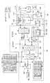
도 3 은 본 발명에 따른 주파수 합성 장치의 일실시예를 나타낸 도면,3 is a view showing an embodiment of a frequency synthesizing apparatus according to the present invention;
도 4는 본 발명에 따른 주파수 합성 장치 내에 있는 주파수 발생 수단의 다른 실시예를 나타낸 도면, 그리고4 shows another embodiment of the frequency generating means in the frequency synthesizing apparatus according to the present invention, and
도 5는 본 발명에 따른 주파수 합성 장치 내에 있는 주파수 조정 수단의 다른 실시예를 나타낸 도면이다.5 shows another embodiment of the frequency adjusting means in the frequency synthesizing apparatus according to the present invention.
*도면의 주요 부분에 대한 부호의 설명** Description of the symbols for the main parts of the drawings *
100 : 주파수 발생 수단 110 : 국부발진기100: frequency generating means 110: local oscillator
130 : 분주수단 150 : 위상 고정 루프130: dispensing means 150: phase locked loop
200 : 주파수 조정 수단 220 : 제 1 혼합부200: frequency adjusting means 220: first mixing portion
240 : 제 1 선택부 260 : 제 2 혼합부240: first selection unit 260: second mixing unit
280 : 제 2 선택부280: second selection unit
본 발명은 주파수 합성 장치에 관한 것으로서, 더욱 상세하게는 멀티 밴드를 사용하여 데이터를 송수신하는 초광대역(Ultra Wide Band : UWB) 무선통신 시스템의 주파수 합성 장치에 관한 것이다.The present invention relates to a frequency synthesizing apparatus, and more particularly, to a frequency synthesizing apparatus of an ultra wide band (UWB) wireless communication system for transmitting and receiving data using multi-bands.
최근 고해상도의 대용량 멀티미디어 데이터에 대한 접속이 점차 보편화됨에 따라 무선 통신 시스템에서도 고속 데이터 전송의 요구가 증대되고 있는 실정이다.Recently, as access to high-capacity large-capacity multimedia data becomes more and more common, demand for high-speed data transmission is increasing in wireless communication systems.
무선 통신 시스템의 경우에 데이터를 전송하기 위해 일정 대역의 주파수를 사용하며, 무선 통신 시스템을 이용하여 전송하고자 하는 데이터의 양이 증가하면서 주파수 대역폭도 증가하고 있다.In the case of a wireless communication system, a frequency of a predetermined band is used to transmit data, and as the amount of data to be transmitted using the wireless communication system increases, the frequency bandwidth also increases.
또한, 통신에 사용되는 데이터는 서킷 데이터(circuit data)과, 패킷 데이터(packet data)로 구분되는데, 서킷 데이터를 전송하기 위해 사용되는 주파수 대역은 일반적으로 협소하지만, 패킷 데이터를 전송하기 위해서는 보다 넓은 주파수 대역을 필요로 한다. 최근에는, 고해상도 대용량 멀티미디어 데이터의 실시간 무선 전송을 위한 초고속 무선통신의 개념이 제시되었으며, 보다 넓은 대역폭이 필요하게 되었다. 이처럼 초고속 무선통신을 위한 넓은 주파수 대역을 초광대역(Ultra Wide Band : 이하 UWB라 칭함)이라 한다.In addition, data used for communication is divided into circuit data and packet data. The frequency band used for transmitting circuit data is generally narrow, but a wider band is used for transmitting packet data. It requires a frequency band. Recently, the concept of ultra-high speed wireless communication for real-time wireless transmission of high resolution mass multimedia data has been proposed, and wider bandwidth is required. Thus, a wide frequency band for ultra high speed wireless communication is called an ultra wide band (hereinafter referred to as UWB).
상기 UWB 통신은 미국 연방통신위원회(Federal Communications Commission :FCC) 에서 인가된 3.1GHz~10.6GHz의 주파수 대역을 활용한 통신을 말하며, 중심주파수 대비 대역폭이 20% 이상이거나 500MHz 이상의 주파수 대역폭을 차지하는 통신 방식을 의미한다. UWB 방식의 신호는 넓은 주파수 대역을 사용할 수 있으므로 주파수 영역에서의 전력 밀도 값을 아주 작은 값으로 할 수 있어 다른 통신신호가 존재하는 주파수에 중첩되어 사용하더라도 간섭을 거의 주지 않을 수 있다는 점에 착안하고 있다. 초기에 제안된 UWB 방식 신호는 아주 짧은 신호 펄스를 사용함으로써 넓은 주파수 대역을 얻었으나 현재는 CDMA(Code Division Multiple Access; 부호 분할 다중 접속), OFDM(Orthogonal Frequency Division Multiplexing; 직교 주파수 분할 다중) 등의 여러 가지 변형된 형태의 UWB 방식이 제안되어 있는 상태이다.The UWB communication refers to a communication using a frequency band of 3.1 GHz to 10.6 GHz licensed by the Federal Communications Commission (FCC), and a communication method that has a bandwidth of 20% or more of the center frequency or 500 MHz or more. Means. As UWB signal can use a wide frequency band, it is possible to set the power density value in the frequency domain to a very small value, so that it can give little interference even when superimposed on the frequency where other communication signals exist. have. Initially, the proposed UWB signal obtained a wide frequency band by using a very short signal pulse, but currently, the code division multiple access (CDMA), orthogonal frequency division multiplexing (OFDM), etc. Various modified UWB schemes have been proposed.
이 중 멀티밴드 OFDM (Multi Band-Orthogonal Frequency Division Multiplexing : MB-OFDM) 방식의 UWB 통신시스템을 살펴보면, 주파수 대역을 일정크기의 복수 개 서브밴드(sub-band)로 구분하여 사용한다. 이러한 UWB 통신 시스템은 상기 복수 개의 서브밴드를 이용하여 데이터를 전송함으로서 단위 시간당 많은 데이터를 송수신할 수 있다. 또한, 상기 복수 개의 서브밴드들 중 하나를 선택하고, 선택된 서브밴드를 이용하여 데이터를 전송함으로서 데이터에 대한 보안성을 높일 수 있다. 즉, 복수 개의 서브밴드들을 순차적으로 사용함으로서 데이터에 대한 보안성을 높일 수 있게 된다.The UWB communication system of the Multi Band-Orthogonal Frequency Division Multiplexing (MB-OFDM) method is divided into a plurality of sub-bands of a predetermined size. The UWB communication system can transmit and receive a lot of data per unit time by transmitting data using the plurality of subbands. In addition, by selecting one of the plurality of subbands and transmitting data using the selected subband, security of data may be enhanced. That is, by using a plurality of subbands in sequence, it is possible to increase the security of the data.
도 1은 멀티밴드 OFDM 방식의 UWB 통신시스템에서 사용하는 주파수 대역을 도시한 도면이다. 도 1에 도시된 바와 같이, 5개의 밴드그룹으로 구분되며, 총 14개의 서브밴드로 구성되는데, 이중 제 1 밴드그룹은 필수이고, 나머지 제 2 밴드그룹부터 제 5 밴드그룹까지는 선택이다.1 is a diagram illustrating a frequency band used in a UWB communication system of a multiband OFDM system. As shown in FIG. 1, it is divided into five band groups and consists of a total of 14 subbands, wherein the first band group is mandatory, and the remaining second band group to the fifth band group are optional.
도 1에 도시된 멀티밴드 OFDM 방식의 밴드 구성을 보면, 제 1 밴드그룹에서 제 4 밴드그룹까지는 각각 3개의 서브밴드로 구성되며, 제 5 밴드그룹은 2개의 서브밴드로 구성된다.Referring to the band configuration of the multi-band OFDM scheme shown in FIG. 1, each of the first band group to the fourth band group includes three subbands, and the fifth band group includes two subbands.
상기 제 1 밴드그룹내의 서브밴드들의 중심주파수(Center Frequency)는 3432㎒, 3960㎒, 4488㎒이며, 제 2 밴드그룹내의 서브밴드들의 중심주파수는 5016㎒, 5544㎒, 6072㎒이고, 제 3 밴드그룹내의 서브밴드들의 중심주파수는 6600㎒, 7128㎒, 7656㎒이며, 제 4 밴드그룹내의 서브밴드들의 중심주파수는 8184㎒, 8712㎒, 9240㎒이며, 제 5 밴드그룹내의 서브밴드들의 중심주파수는 9768㎒, 10296㎒이다.The center frequencies of the subbands in the first band group are 3432 MHz, 3960 MHz, and 4488 MHz. The center frequencies of the subbands in the second band group are 5016 MHz, 5544 MHz, and 6072 MHz. The center frequencies of the subbands in the group are 6600 MHz, 7128 MHz, and 7656 MHz. The center frequencies of the subbands in the fourth band group are 8184 MHz, 8712 MHz, and 9240 MHz, and the center frequencies of the subbands in the fifth band group are 9768 MHz and 10296 MHz.
이러한 멀티밴드 OFDM 방식의 밴드 플랜은 기술변화에 따라 변경될 가능성이 있다.The band plan of the multi-band OFDM scheme may change according to technology change.
상술한 바와 같이 UWB 통신 시스템에서 사용하는 중심주파수를 갖는 신호들을 생성하기 위한 구성이 필수적으로 필요하다.As described above, a configuration for generating signals having a center frequency used in the UWB communication system is essential.
도 2는 제 1 밴드그룹 내에 있는 3 개의 서브밴드의 중심주파수를 생성하기 위한 종래의 주파수 합성 장치를 나타낸 도면이다.2 is a diagram illustrating a conventional frequency synthesizer for generating center frequencies of three subbands within a first band group.
도 2에 도시된 주파수 합성 장치는 다이렉트 컨버젼(Direct Conversion) 멀티 밴드 OFDM UWB 시스템에서 사용되는 구조로서, 국부발진기(10), 위상 고정 루프(20, Phase Locked Loop, : PLL), 제 1/8 분주기(30), 제 1/2 분주기(40), 제 1 SSB 믹서(Single Side Band Mixer)(50), 선택부(60), 및 제 2 SSB 믹서(70)로 구성된다.The frequency synthesizer shown in FIG. 2 is a structure used in a direct conversion multi-band OFDM UWB system, and includes a local oscillator 10, a phase locked loop (PLL), and a first eighth. A divider 30, a 1/2
이하, 제 1 밴드그룹 내에 있는 3 개의 서브밴드의 중심주파수를 생성하기 위한 동작원리를 살펴보면 다음과 같다.Hereinafter, an operation principle for generating center frequencies of three subbands in a first band group will be described.
국부 발진기(10)는 상기 3개의 서브밴드의 중심주파수인 3432㎒, 3960㎒, 및 4488㎒를 생성하기 위해, 고정된 발진주파수로 설정되어 4224㎒의 주파수를 갖는 신호를 생성한다.Local oscillator 10 generates a signal having a frequency of 4224 MHz, set to a fixed oscillation frequency, to produce the center frequencies 3432 MHz, 3960 MHz, and 4488 MHz of the three subbands.
위상 고정 루프(PLL:Phase Lock Loop)(20)은 상기 국부 발진기(10)에서 생성된 신호의 주파수를 안정시키는 동작을 수행한다.A phase lock loop (PLL) 20 stabilizes the frequency of the signal generated by the local oscillator 10.
제 1/8 분주기(30)는 상기 국부 발진기(10)로부터 4224MHz의 주파수 신호를 입력받아, 1/8로 분주함으로써 528MHz의 조정주파수 신호를 생성한다.The first eighth frequency divider 30 receives a 4224 MHz frequency signal from the local oscillator 10 and divides the frequency into one eighth to generate a 528 MHz adjusted frequency signal.
제 1/2 분주기(40)는 상기 제 1/8 분주기(30)로부터의 신호를 입력받아, 1/2로 분주함으로써 264MHz의 조정주파수 신호를 생성한다.The 1/2
제 1 SSB 믹서(50)는 상기 제 1/8 분주기(30)로부터의 528MHz의 조정주파수 신호와, 상기 제 1/2 분주기(40)로부터의 264MHz의 조정주파수 신호를 입력받아, 믹싱을 수행함으로써 792MHz의 조정주파수 신호를 생성한다.The
선택부(60)는 상기 제 1/2 분주기(40)로부터 264MHz의 조정주파수 신호와, 제 1 SSB 믹서(50)로부터 792MHz의 조정주파수 신호를 입력받아, 둘 중 하나의 신호를 선택한다.The
제 2 SSB 믹서(70)는 상기 국부 발진기(10)로부터 4224㎒의 주파수 신호, 및 상기 선택부(60)에서 선택되는 신호인 264MHz 또는 792MHz를 입력받아, 믹싱을 수행함으로써 원하는 3개의 서브밴드 중심주파수인 3432㎒, 3960㎒, 4488㎒를 생성한다. 즉, 제 2 SSB 믹서(70)는 4224㎒와 264MHz의 주파수 신호를 합산하여 4488㎒ 의 주파수 신호를 발생하고, 4224㎒와 264MHz의 주파수 신호를 감산하여 3960㎒의 주파수 신호를 발생한다. 그리고, 4224㎒와 792MHz의 주파수 신호를 감산하여 3432㎒의 주파수 신호를 발생한다.The
상술한 종래의 주파수 합성 장치는 현재 활용되고 있는 제 1 밴드 그룹 내에 있는 3개 서브밴드의 중심주파수 만을 생성하도록 되어 있으나, 이는 전적으로 반도체 기술수준이 높은 주파수 대역의 서브밴드를 지원하지 못하기 때문이다. 또한, 복잡한 무선서비스의 환경에서 간섭없는 안정된 UWB통신을 위해서는 서브밴드의 확장을 통한 주파수의 유연한 활용이 필요하고, 궁극적으로는 제 1 밴드그룹에서 제5 밴드그룹의 14개의 모든 서브밴드를 활용하는 UWB 통신이 이루어지게 될 것이다.The conventional frequency synthesizer described above generates only the center frequencies of the three subbands within the first band group currently being used, but this is because the semiconductor technology level does not fully support the subbands of the high frequency band. . In addition, in the complex wireless service environment, stable UWB communication without interference requires flexible utilization of frequencies through extension of subbands, and ultimately utilizes all 14 subbands of the fifth band group in the first band group. UWB communication will take place.
따라서, 상기 필요성을 만족하기 위한 본 발명의 목적은 멀티 밴드를 사용하여 데이터를 송수신하는 초광대역 무선통신 시스템에 있어서 신호의 전송 및 수신을 위해 복수개의 서브밴드의 중심 주파수 신호 생성이 가능한 주파수 합성 장치를 제공함에 있다.Accordingly, an object of the present invention to satisfy the above necessity is a frequency synthesizing apparatus capable of generating center frequency signals of a plurality of subbands for transmitting and receiving signals in an ultra-wideband wireless communication system for transmitting and receiving data using multibands. In providing.
상기한 목적을 달성하기 위한 본 발명에 따른 주파수 합성 장치는 주파수 발생 수단 및 주파수 조정 수단으로 구성된다.A frequency synthesizing apparatus according to the present invention for achieving the above object is composed of a frequency generating means and a frequency adjusting means.
즉, 본 발명의 주파수 합성 장치는 멀티 밴드를 사용하여 데이터를 송수신하는 광대역 무선통신 시스템에 있어서, 복수개의 주파수 신호를 발생하는 주파수 발생 수단 및 상기 주파수 발생 수단으로부터 복수개의 주파수 신호를 입력받아 주파 수 조정을 통해 상기 초광대역 내의 모든 서브밴드 또는 일부 서브밴드의 중심주파수를 생성하는 주파수 조정수단을 포함한다.That is, the frequency synthesizing apparatus of the present invention is a wideband wireless communication system for transmitting and receiving data using multi-bands, the frequency generating means for generating a plurality of frequency signals and a plurality of frequency signals from the frequency generating means received the frequency Frequency adjustment means for generating a center frequency of all subbands or some subbands in the ultra-wideband through the adjustment.
여기서, 상기 주파수 발생 수단은 주파수 제어신호에 따라 발진 주파수를 생성하는 국부발진기, 상기 국부발진기로부터의 주파수 신호를 입력받아 분주된 복수개의 주파수 신호를 출력하는 분주수단 및 기준주파수 신호를 입력받고 상기 분주수단으로부터의 분주된 주파수 신호를 입력받아 주파수를 안정시키는 동작을 수행하기 위한 상기 주파수 제어신호를 출력하는 위상고정루프를 포함한다.Here, the frequency generating means receives a local oscillator for generating an oscillation frequency according to a frequency control signal, a frequency divider for receiving a frequency signal from the local oscillator, and outputs a plurality of divided frequency signals and a reference frequency signal. And a phase locked loop for receiving the divided frequency signal from the means and outputting the frequency control signal for performing the operation of stabilizing the frequency.
바람직하게는 상기 국부발진기는 주파수 제어신호에 따라 모든 서브밴드의 중심주파수를 생성하기 위해 12672MHz의 주파수 신호를 생성한다.Preferably, the local oscillator generates a frequency signal of 12672 MHz to generate the center frequency of all subbands according to the frequency control signal.
또한, 상기 분주수단은 상기 국부발진기로부터의 주파수 신호를 입력받아 복수개의 분주된 주파수 신호를 출력하는 제 1 분주부와 제 2 분주부를 포함한다.In addition, the dividing means includes a first divider and a second divider for receiving a frequency signal from the local oscillator and outputting a plurality of divided frequency signals.
이중에서, 상기 제 1 분주부는 상기 국부발진기로부터의 주파수 신호를 입력받아 1/3 분주된 주파수 신호를 출력하는 제 1 분주기, 상기 제 1 분주기로부터 1/3 분주된 주파수 신호를 입력받아 1/4 분주된 주파수 신호를 출력하는 제 2 분주기 및 상기 제 2 분주기로부터 1/4 분주된 주파수 신호를 입력받아 1/4 분주된 주파수 신호를 출력하는 제 3 분주기를 포함한다.Among these, the first divider receives a frequency signal received from the local oscillator and outputs a frequency signal divided by three, and receives a frequency signal divided by one third from the first divider. And a second divider for outputting a 1/4 divided frequency signal and a third divider for receiving a 1/4 divided frequency signal from the second divider and outputting a 1/4 divided frequency signal.
바람직하게는 상기 제 1 분주기로부터의 주파수 신호는 4224MHz의 신호이고, 상기 제 2 분주기로부터의 주파수 신호는 1056MHz의 신호이며, 상기 제 3 분주기로부터의 주파수 신호는 264MHz의 신호이다.Preferably, the frequency signal from the first divider is a signal of 4224 MHz, the frequency signal from the second divider is a signal of 1056 MHz, and the frequency signal from the third divider is a signal of 264 MHz.
한편, 상기 제 2 분주부는 상기 국부발진기로부터의 주파수 신호를 입력받아 1/2 분주된 주파수 신호를 출력하는 제 1 분주기와 상기 제 1 분주기로부터의 주파수 신호를 입력받아 1/2 분주된 주파수 신호를 출력하는 제 2 분주기로 구성된다.Meanwhile, the second divider receives a frequency signal from the local oscillator, receives a first divider for outputting a frequency signal divided by half, and receives a frequency signal from the first divider. And a second divider for outputting a frequency signal.
바람직하게는 상기 제 1 분주기로부터의 주파수 신호는 6336MHz의 신호이고, 상기 제 2 분주기로부터의 주파수 신호는 3168MHz의 신호이다.Preferably, the frequency signal from the first divider is a 6336 MHz signal, and the frequency signal from the second divider is a 3168 MHz signal.
이어서, 상기 주파수 조정 수단는 제어신호에 따라 상기 주파수 발생 수단으로부터의 주파수 신호를 입력받아 복수개의 주파수 신호를 생성하는 제 1 혼합부,선택신호에 따라 상기 주파수 발생 수단으로부터의 주파수 신호를 입력받아 선택된 주파수 신호를 출력하는 제 1 선택부, 상기 제 1 혼합부로부터 생성된 주파수 신호와 상기 제 1 선택부로부터의 선택된 주파수 신호를 입력받아 복수개의 주파수 신호를 생성하는 제 2 혼합부 및 상기 제 2 혼합부로부터 생성된 복수개의 주파수 신호를 입력받아 선택된 주파수 신호를 출력하는 제 2 선택부로 구성된다.Subsequently, the frequency adjusting means receives a frequency signal from the frequency generating means in accordance with a control signal and generates a plurality of frequency signals, and receives a frequency signal from the frequency generating means in accordance with a selection signal and selects a selected frequency. A first mixing unit for outputting a signal, a second mixing unit for generating a plurality of frequency signals by receiving a frequency signal generated from the first mixing unit and a selected frequency signal from the first selecting unit, and the second mixing unit And a second selector configured to receive a plurality of frequency signals generated from the plurality and to output a selected frequency signal.
바람직하게는 상기 제 1 혼합부는 1320MHz, 792MHz, 264MHz의 주파수 신호들을 생성한다.Preferably, the first mixing unit generates frequency signals of 1320 MHz, 792 MHz, and 264 MHz.
그리고, 상기 제 1 선택부는 선택신호에 따라 상기 주파수 발생 수단으로부터 6336MHz 및 3168MHz의 주파수 신호 중 하나의 주파수 신호를 선택한다.The first selector selects one of the frequency signals of 6336 MHz and 3168 MHz from the frequency generating means in accordance with the selection signal.
또한, 상기 제 2 혼합부는 제어신호에 따라 상기 제 1 혼합부로부터 생성된 주파수 신호와 상기 제 1 선택부로부터의 선택된 주파수 신호를 입력받아 복수개의 주파수 신호를 생성하는 제 1 혼합기와 상기 제 1 혼합기로부터 생성된 복수개의 주파수 신호를 입력받아 또 다른 복수개의 주파수 신호를 생성하는 제 2 혼합기를 포함한다.The second mixer may include a first mixer and the first mixer configured to generate a plurality of frequency signals by receiving a frequency signal generated from the first mixer and a selected frequency signal from the first selector according to a control signal. And a second mixer configured to receive the plurality of frequency signals generated from the second frequency signal.
바람직하게는 상기 제 1 혼합기에서 생성된 복수개의 주파수 신호는 제 1 밴드그룹에서 제 3 밴드그룹까지의 중심주파수이며, 상기 제 2 혼합기에서 생성된 복수개의 주파수 신호는 제 4 밴드그룹에서 제 5 밴드그룹까지의 중심주파수이다.Preferably, the plurality of frequency signals generated by the first mixer are center frequencies from the first band group to the third band group, and the plurality of frequency signals generated by the second mixer are fifth bands in the fourth band group. The center frequency to the group.
또한, 상기 제 1 밴드그룹에서 상기 제 3 밴드그룹까지의 중심주파수 신호는 3432㎒, 3960㎒, 4488㎒, 5016㎒, 5544㎒, 6072㎒, 6600㎒, 7128㎒, 7656㎒ 의 신호이고, 상기 제 4 밴드그룹에서 상기 제 5 밴드그룹까지의 중심주파수 신호는 8184㎒, 8712㎒, 9240㎒, 9768㎒, 10296㎒ 의 신호이다.The center frequency signal from the first band group to the third band group is a signal of 3432 MHz, 3960 MHz, 4488 MHz, 5016 MHz, 5544 MHz, 6072 MHz, 6600 MHz, 7128 MHz, 7656 MHz, The center frequency signal from the fourth band group to the fifth band group is 8184 MHz, 8712 MHz, 9240 MHz, 9768 MHz, 10296 MHz.
이하 첨부된 도면을 참조하여 본 발명을 상세하게 설명한다.Hereinafter, the present invention will be described in detail with reference to the accompanying drawings.
도 3 은 본 발명에 따른 주파수 합성 장치의 일실시예를 나타낸 도면이다.3 is a diagram illustrating an embodiment of a frequency synthesizing apparatus according to the present invention.
도 3 에 도시된, 본 발명의 주파수 합성 장치는, 정해진 대역 내의 중심주파수 생성시 이용되는 주파수를 발생시키는 주파수 발생 수단(100)과, 주파수 발생 수단(100)으로부터 생성된 주파수를 조정하여 정해진 대역내의 모든 서브밴드 또는 일부 서브밴드의 중심주파수를 생성하는 주파수 조정 수단(200)으로 구성된다.The frequency synthesizing apparatus of the present invention, shown in FIG. 3, includes a frequency generating means 100 for generating a frequency used when generating a center frequency within a predetermined band, and a band determined by adjusting a frequency generated from the frequency generating means 100. And frequency adjusting means 200 for generating a center frequency of all subbands or some subbands in the apparatus.
여기서, 정해진 대역은 초광대역으로, 정해진 대역 내에 있는 모든 서브대역의 중심주파수는 3.1GHz~10.6GHz 범위 내에 있는 모든 서브대역의 중심주파수를 말한다. 따라서, 모든 서브대역의 중심주파수는, 도 1에 도시된 바와 같이, 제 1 밴드그룹부터 제 5 밴드그룹까지의 서브밴드들의 중심주파수를 말하는 것으로, 3432㎒, 3960㎒, 4488㎒, 5016㎒, 5544㎒, 6072㎒, 6600㎒, 7128㎒, 7656㎒, 8184㎒, 8712㎒,9240㎒, 9768㎒, 10296㎒인 14개의 서브밴드 중심주파수를 말한다. 이러한 서브밴드의 중심주파수는 한정적이지 않으며 기술변화에 따라 변경될 가능성이 있 다.Here, the predetermined band is an ultra-wide band, and the center frequency of all subbands within the predetermined band refers to the center frequency of all subbands within the range of 3.1 GHz to 10.6 GHz. Accordingly, the center frequencies of all the subbands refer to the center frequencies of the subbands from the first band group to the fifth band group, as shown in FIG. 1, wherein 3432 MHz, 3960 MHz, 4488 MHz, 5016 MHz, 14 subband center frequencies of 5544 MHz, 6072 MHz, 6600 MHz, 7128 MHz, 7656 MHz, 8184 MHz, 8712 MHz, 9240 MHz, 9768 MHz, 10296 MHz. The center frequency of these subbands is not limited and may change due to technological change.
구체적으로 살펴보면, 상기 주파수 발생 수단(100)은, 국부발진기(110), 분주수단(130), 및 위상고정루프(PLL:Phase Lock Loop)(150)로 구성된다.Specifically, the frequency generating means 100 is composed of a
상기 국부발진기(110)는, 주파수 제어신호에 따라 발진 주파수를 생성한다. 이때, 상기 국부발진기(110)는 주파수 제어신호에 따라 모든 서브밴드의 중심주파수를 생성하기 위해 12672MHz의 주파수 신호를 생성한다.The
상기 분주수단(130)은, 제 1 분주부(132)와 제 2 분주부(134)를 포함하며, 상기 국부발진기(110)로부터의 주파수 신호를 입력받아 분주된 복수개의 주파수 신호를 출력한다. 상기 제 1, 2 분주부(132, 134)는 상기 국부발진기(110)로부터의 12672MHz인 주파수 신호를 입력받아 복수개의 분주된 주파수 신호를 출력한다.The dispensing means 130 includes a
먼저, 상기 제 1 분주부(132)는 제 1 분주기(132-1), 제 2 분주기(132-2), 및 제 3 분주기(132- 3)로 구성된다. 상기 제 1 분주기(132-1)는, 상기 국부발진기(110)로부터의 12672MHz인 주파수 신호를 입력받아 1/3 분주된 주파수 신호를 출력하고, 상기 제 2 분주기(132-2)는 상기 제 1 분주기(132-1)로부터 1/3 분주된 주파수 신호를 입력받아 1/4 분주된 주파수 신호를 출력한다. 그리고, 상기 제 3 분주기(132-3)는 상기 제 2 분주기(132-2)로부터 1/4 분주된 주파수 신호를 입력받아 1/4 분주된 주파수 신호를 출력한다.First, the
따라서, 상기 제 1 분주기(132-1)는, 상기 국부발진기(110)로부터의 12672MHz인 주파수 신호를 입력받아 1/3 분주한 신호인 4224MHz의 Quadrature 신호를 출력하고, 상기 제 2 분주기(132-2)는, 상기 제 1 분주기(132-1)로부터 1/3 분 주된 주파수 신호인 4224MHz Quadrature 신호를 입력받아 1/4 분주한 신호인 1056MHz의 Quadrature 신호를 출력한다. 그리고, 상기 제 3 분주기(132-3)는, 상기 제 2 분주기(132-2)로부터 1/4 분주된 주파수 신호인 1056MHz의 Quadrature 신호를 입력받아 1/4 분주한 신호인 264MHz의 Quadrature 신호를 출력한다.Accordingly, the first divider 132-1 receives a frequency signal of 12672 MHz from the
그리고, 상기 제 2 분주부(134)는, 제 1 분주기(134-1)와 제 2 분주기(134-2)로 구성된다. 상기 제 1 분주기(134-1)는 상기 국부발진기(110)로부터의 12672MHz인 주파수 신호를 입력받아 1/2 분주한 주파수 신호인 6336MHz의 Quadrature 신호를 출력하며, 상기 제 2 분주기(134-2)는 상기 제 1 분주기(134-1)로부터의 주파수 신호인 6336MHz의 Quadrature 신호를 입력받아 1/2 분주한 주파수 신호인 3168MHz의 Quadrature 신호를 출력한다.The
상기 위상고정루프(150)는 기준주파수 신호를 입력받고, 상기 분주수단(130)으로부터의 분주된 주파수 신호를 입력받아 주파수를 안정시키는 동작을 수행하기 위한 상기 주파수 제어신호를 출력한다.The phase locked loop 150 receives a reference frequency signal and outputs the frequency control signal for performing an operation of stabilizing the frequency by receiving the divided frequency signal from the dividing means 130.
즉, 위상고정루프(PLL: 150)는 외부(도시하지 않음)로부터 기준주파수 신호를 입력는다. 그리고, 상기 분주수단(130)내에 있는 상기 제 1 분주부(132)의 상기 제 3 분주기(132-3)로부터의 분주된 주파수 신호인 264MHz의 신호를 입력받아, 주파수를 안정시키는 동작을 수행하기 위한 상기 주파수 제어신호를 출력한다.That is, the phase locked loop PLL 150 receives a reference frequency signal from the outside (not shown). In addition, a signal of 264 MHz, which is a divided frequency signal from the third divider 132-3 of the
한편, 상기 주파수 조정 수단(200)는, 제 1 혼합부(220), 제 1 선택부(240), 제 2 혼합부(260), 및 제 2 선택부(280)로 구성된다.In addition, the frequency adjusting means 200 includes a
상기 제 1 혼합부(220)는, 제어신호에 따라 상기 주파수 발생 수단(100)에서 생성된 주파수 신호를 입력받아 복수개의 주파수 신호를 생성한다. 구체적으로, 제 1 혼합부(220)는, 제1 분주부(132)의 제2 분주기(132-2)와 제3 분주기(132-3)로부터 각각 1056MHz, 264MHz의 신호를 입력받아 1320MHz, 792MHz, 264MHz의 주파수 신호들을 생성한다. 즉, 제 1 혼합부(220)는 입력받은 1056MHz, 264MHz의 신호를 제어신호에 따라 가산 및 감산하여 1320MHz, 792MHz의 Quadrature 신호를 생성하여 출력하며, 제3 분주기(132-3)로부터 입력받은 264MHz의 신호를 출력한다.The
상기 제 1 선택부(240)는 선택신호에 따라 상기 주파수 발생 수단(100)으로부터의 주파수 신호를 입력받아 선택되는 주파수 신호를 출력한다. 즉, 상기 제 1 선택부(240)는, 제2 분주부(134)의 제1 분주기(134-1)와 제2 분주기(134-2)으로부터 6336MHz 및 3168MHz의 주파수 신호를 각각 입력받은 후, 선택신호에 따라 6336MHz 및 3168MHz의 주파수 신호 중 어느 하나의 신호를 선택하여 출력한다.The
상기 제 2 혼합부(260)는, 제 1 혼합기(262)와 제 2 혼합기(264)를 포함하며, 상기 제 1 혼합부(220)로부터 생성된 주파수 신호와, 상기 제 1 선택부(240)로부터의 선택된 주파수 신호를 입력받아 복수개의 주파수 신호를 생성한다.The
먼저, 제2 혼합부(260)의 제 1 혼합기(262)는 제어신호에 따라, 상기 제 1 혼합부(220)로부터 생성된 주파수 신호와, 상기 제 1 선택부(240)로부터의 선택된 주파수 신호를 입력받아 복수개의 주파수 신호를 생성한다. 구체적으로, 제 1 혼합기(262)는, 제1 혼합부(220)로부터의 1320MHz, 792MHz, 264MHz의 신호와, 제 1 선택부(240)로부터의 6336MHz, 3168MHz의 신호들을 제어신호에 따라 적절히 합산하여 3432㎒, 3960㎒, 4488㎒, 5016㎒, 5544㎒, 6072㎒, 6600㎒, 7128㎒, 7656㎒의 주파 수 신호를 생성한다. 따라서, 상기 제 1 혼합기(262)에서 생성된 복수개의 주파수 신호는 도 1에 도시된 제 1 밴드그룹에서 제 3 밴드그룹까지의 중심주파수에 해당한다.First, the
그리고, 상기 제 2 혼합기(264)는, 상기 제 1 혼합기(262)로부터 생성된 복수개의 주파수 신호, 및 제 1 분주부(132)의 제 2 분주기(132-2)의 주파수 신호를 입력받아 또 다른 복수개의 주파수 신호를 생성한다. 구체적으로, 제 2 혼합기(264)는, 제 1 혼합기(262)로부터의 3432㎒, 3960㎒, 4488㎒, 5016㎒, 5544㎒, 6072㎒, 6600㎒, 7128㎒, 7656㎒의 신호, 및 제 2 분주부(134)의 제 2 분주기(134-2)로부터의 3168MHz의 신호들을 제어신호에 따라 적절히 합산하여, 8184㎒, 8712㎒, 9240㎒, 9768㎒, 10296㎒의 주파수 신호를 생성한다. 따라서, 제 2 혼합기(264)에서 생성된 복수개의 주파수 신호는, 제 4 밴드그룹에서 제 5 밴드그룹까지의 중심주파수에 해당한다.The
그리고, 상기 제 2 선택부(280)는, 제1 혼합기(262)와 제2 혼합기(264)를 포함하는 제 2 혼합부(260)로부터 생성된 복수개의 주파수 신호들을 입력받아, 선택신호에 따라 선택되는 주파수 신호를 출력한다.The
즉, 제 2 선택부(280)는 상기 제 1 혼합기(262)에서 생성된 제 1 밴드그룹에서 제 3 밴드그룹까지의 중심주파수 신호인 3432㎒, 3960㎒, 4488㎒, 5016㎒, 5544㎒, 6072㎒, 6600㎒, 7128㎒, 7656㎒와, 상기 제 2 혼합기(264)에서 생성된 제 4 밴드그룹에서 제 5 밴드그룹까지의 중심주파수 신호인 8184㎒, 8712㎒, 9240㎒, 9768㎒, 10296㎒를 입력받아, 선택신호에 따라 선택되는 주파수 신호를 출력한다. 따라서, 제 2 선택부(280)는, 제 1 밴드그룹에서 제 5 밴드그룹까지의 초광대역(3.1GHz ~10.6 GHz)의 모든 대역내에 있는 서브밴드의 중심주파수를 생성할 수 있다.That is, the
도 4는 본 발명에 따른 주파수 합성 장치 내에 있는 주파수 발생 수단(300)의 다른 실시예를 나타낸 도면이다.4 shows another embodiment of the frequency generating means 300 in the frequency synthesizing apparatus according to the present invention.
도 4의 주파수 발생수단(300)은, 도 3의 주파수 발생수단(100)과 달리 도 3의 주파수 발생수단(100)의 제2 분주부(132)의 제1 분주기(134-1) 대신 신호 변환부(334)를 이용한다.Unlike the frequency generating means 100 of FIG. 3, the frequency generating means 300 of FIG. 4 replaces the first divider 134-1 of the
도 4 에 도시한 바와 같이, 본 발명의 주파수 발생 수단(300)은, 국부발진기(310), 분주수단(330), 위상고정루프(PLL: 350), 및 신호 변환부(370)로 구성된다.As shown in FIG. 4, the frequency generating means 300 according to the present invention includes a
상기 국부발진기(310)는, 주파수 제어신호에 따라 발진 주파수를 생성한다. 이때, 상기 국부발진기(310)는 주파수 제어신호에 따라 모든 서브밴드의 중심주파수를 생성하기 위해, 6336MHz의 주파수 신호를 생성한다.The
여기서, 도 3에서 국부발진기(110)로부터의 신호를 1/2 분주하는 1/2 분주기인 제1 분주기(134-1)가, 도 4에서는 입력되는 신호의 위상을 90도 천이하는 신호변환부(334)로 대체됨으로써, 도 3과 도 4의 주파수 발생수단이 복수개의 동일한 주파수 신호들을 생성하기 위해 도 4의 국부발진기(310)의 발진 주파수는 도 3의 국부발진기(110)의 발진 주파수 12672MHz의 1/2인 6336MHz로 한다.Here, in FIG. 3, the first divider 134-1, which is a 1/2 divider for dividing the signal from the
상기 분주수단(330)은 제 1 분주부(332)와 제 2 분주부(334)로 구성되며, 상기 국부발진기(310)로부터의 주파수 신호를 입력받아 분주된 복수개의 주파수 신호 를 출력한다. 제1, 제2 분주부(332, 334)는 상기 국부발진기(310)로부터의 주파수 신호인 6336MHz를 각각 입력받아, 복수개의 분주된 주파수 신호를 출력한다.The dispensing means 330 includes a
이때, 상기 제 1 분주부(332)는 제 1 분주기(332-1), 제 2 분주기(332-2), 및 제 3 분주기(332-3)를 포함한다. 상기 제 1 분주기(332-1)는 상기 국부발진기(310)로부터의 주파수 신호 6336MHz를 입력받아 1/3 분주한 주파수 신호 2112MHz를 출력하며, 상기 제 2 분주기(332-2)는 상기 제 1 분주기(332-1)로부터 1/3 분주된 주파수 신호 2112MHz를 입력받아 1/2 분주한 주파수 신호 1056MHz를 출력한다. 그리고, 상기 제 3 분주기(332-3)는 상기 제 2 분주기(332-2)로부터 1/2 분주된 주파수 신호 1056MHz를 입력받아, 1/4 분주한 주파수 신호 256MHz를 출력한다.In this case, the
여기서, 상기 제 2 분주기(332-2)로부터의 1056MHz의 신호와 상기 제 3 분주기(332-3)로부터의 264MHz신호는, 도 3의 주파수 발생수단(100)과 같이 중심주파수를 생성하는 주파수 조정 수단의 입력신호로 사용된다.Here, the 1056 MHz signal from the second divider 332-2 and the 264 MHz signal from the third divider 332-3 generate the center frequency as in the frequency generating means 100 of FIG. 3. It is used as an input signal for frequency adjusting means.
그리고, 상기 제 2 분주부(334)는 상기 국부발진기(310)로부터의 주파수 신호 6336 MHz를 입력받아 1/2 분주된 주파수 신호를 출력한다. 따라서, 제 2 분주부(334)로부터의 주파수 신호는 국부발진기(310)의 출력신호 6336MHz의 1/2인 3168MHz이며, 이 신호는 도 3의 주파수 발생수단(100)과 같이 주파수 조정수단의 입력신호로 사용된다.The
상기 위상고정루프(350)는 기준주파수 신호를 입력받고, 상기 분주수단(330)으로부터의 분주된 주파수 신호를 입력받아 주파수를 안정시키는 동작을 수행하기 위한 상기 주파수 제어신호를 출력한다. 즉, 위상고정루프(PLL: 350)는 기준주파수 신호를 입력받고, 상기 분주수단(330)내에 있는 상기 제 1 분주부(332)의 상기 제 3 분주기(332-3)로부터의 분주된 주파수 신호 264MHz를 입력받아 주파수를 안정시키는 동작을 수행하기 위한 상기 주파수 제어신호를 출력한다.The phase locked
상기 신호 변환부(370)는 상기 국부발진기(310)로부터의 주파수 신호 6336MHz를 입력받아 신호의 위상을 90도 천이하여 그 위상이 각각 90도씩 차이가 나는 동위상(In-phase) 신호 및 직교위상(Q : Quadrature) 신호로 변환하여 출력한다. 이때, 신호 변환부(370)는 다중 위상 필터(Poly Phase Filter : PPF)로 구현될 수 있다.The
또한, 신호 변환부(370)는 상기 국부발진기(310)로부터 6336MHz의 디퍼런셜(Differential) 신호를 입력받아 디퍼런셜 I/Q 신호를 출력한다. 이때의 상기 신호변환부(370)의 출력 신호는 주파수 조정 수단의 입력신호로 사용된다.In addition, the
여기서, 상기 국부발진기(310)로부터 6336MHz의 디퍼런셜(Differential) I/Q신호가 생성될 경우, 상기 신호변환부(370)는 생략 가능하다. 이때, 상기 국부발진기로부터 생성된 6336MHz의 디퍼런셜(Differential) I/Q신호가 직접 주파수 조정 수단의 입력신호로 사용된다.In this case, when a differential I / Q signal of 6336 MHz is generated from the
한편, 도 4에서 국부발진기(310)의 발진주파수를 6336MHz에서 6336MHz의 1/2인 3168MHz로 설정하여, 1/2 분주기인 제1 분주부(332)의 제2 분주기(332-2)와 제 2 분주부(334)를 생략할 수 있다.Meanwhile, in FIG. 4, the oscillation frequency of the
국부발진기(310)의 발진주파수를 3168MHz로 설정할 경우, 제1 분주기(332-1)는 발진주파수를 1/3 분주하여 1056MHz를 출력하며 제3 분주기(332-3)는 제1 분주 기(323-1)의 신호 1056MHz를 입력받아 1/4 분주함으로써 264MHz 신호를 출력할 수 있다.When the oscillation frequency of the
따라서, 제1 분주부(332)에서 출력되는 신호는 1056MHz, 264MHz로 도 4에서 국부발진기(310)의 발진주파수 6336MHz를 이용하는 경우와 동일하다. 또한, 신호 변환부(334)에서 출력되는 신호는 3168MHz로, 제 2 분주부(334)로부터 주파수 조정수단의 제2 혼합기(264)로 입력되는 신호는 동일하다.Therefore, the signal output from the
도 5는 본 발명에 따른 주파수 합성 장치 내에 있는 주파수 조정 수단의 다른 실시예를 나타낸 도면이다. 도 5의 주파수 조정수단(400)은 도 3의 주파수 조정수단(200)의 제1 선택부(240)가 하나의 스위치로 구현되는 것과 달리, 주파수 조정수단(400)의 제1 선택부(440)은 두 개의 스위치 제1 스위치(440-1)와 제2 스위치(440-2)를 구비한다.5 shows another embodiment of the frequency adjusting means in the frequency synthesizing apparatus according to the present invention. The frequency adjusting means 400 of FIG. 5 is different from that in which the
도 5에 도시된, 본 발명에 따른 주파수 조정 수단(400)의 입력신호로는 도 3에 도시된 주파수 발생 수단(100) 또는 도 4 에 도시된 주파수 발생 수단(300)으로부터의 출력신호가 사용된다.As an input signal of the frequency adjusting means 400 according to the present invention shown in FIG. 5, an output signal from the frequency generating means 100 shown in FIG. 3 or the frequency generating means 300 shown in FIG. 4 is used. do.
도 5를 참조하면, 본 발명의 주파수 조정 수단(400)은 제 1 혼합부(420), 제 1 선택부(440), 제 2 혼합부(460), 및 제 2 선택부(480)로 구성된다.Referring to FIG. 5, the frequency adjusting means 400 of the present invention includes a
상기 제 1 혼합부(420)는 제어신호에 따라 주파수 발생 수단의 주파수 신호를 입력받아 복수개의 주파수 신호를 생성한다. 제1 혼합부(420)는 주파수 발생 수단으로부터 1056MHz와 264MHz 신호를 입력받은 후, 제어신호에 따라 1056MHz와 264MHz 신호를 가산 및 감산하여 1320MHz 와 792MHz 신호를 출력한다.The
상기 제 1 선택부(440)는 제 1 스위치(440-1)와 제 2 스위치(440-2)를 포함하며, 상기 주파수 발생 수단으로부터의 주파수 신호, 및 상기 제 1 혼합부(420)으로부터의 주파수 신호를 입력받아 선택신호에 따라 선택된 주파수 신호를 출력한다.The
이때, 제 1 스위치(440-1)는 선택신호에 따라 상기 주파수 발생 수단으로부터의 6336 MHz 및 3168MHz 주파수 신호 중 하나의 주파수 신호를 선택한다. 그리고, 상기 제 2 스위치(440-2)는 선택신호에 따라 상기 주파수 발생 수단으로부터의 264 MHz 주파수 신호와, 상기 제 1 혼합부(420)로부터의 1320MHz 또는 792MHz의 주파수 신호를 입력받아 하나의 주파수 신호를 선택한다.At this time, the first switch 440-1 selects one frequency signal of the 6336 MHz and 3168 MHz frequency signals from the frequency generating means according to the selection signal. The second switch 440-2 receives a 264 MHz frequency signal from the frequency generator and a 1320 MHz or 792 MHz frequency signal from the
따라서, 제 1 선택부(440)는 6336 MHz, 3168MHz, 1320MHz, 792MHz, 또는 264 MHz의 신호 중 어느 하나의 신호를 출력한다.Accordingly, the
상기 제 2 혼합부(460)는 제 1 혼합기(462) 및 제 2 혼합기(464)를 포함하며, 상기 제 1 선택부(440)로부터의 선택된 주파수 신호를 입력받아 제어신호에 따라 복수개의 주파수 신호를 생성한다.The
상기 제 1 혼합기(462)는 제어신호에 따라 상기 제 1 선택부(440)로부터 선택된 주파수 신호를 입력받아 복수개의 주파수 신호를 생성한다. 이때, 제1 혼합기(462)에서 생성되는 신호는 도 1에 도시된 제 1 밴드그룹에서 제 3 밴드그룹까지의 서브밴드 중심주파수들에 해당한다. 제 1 선택부(440)는 6336 MHz, 3168MHz, 1320MHz, 792MHz, 또는 264 MHz의 신호 중 어느 하나의 신호를 출력하므로, 상기 제 1 혼합기(462)는 제1 선택부(440)에서 출력되는 신호를 제어신호에 따라 적절히 합산함으로써 제1 밴드그룹에서 제3 밴드그룹의 중심주파수인 3432㎒, 3960㎒, 4488㎒, 5016㎒, 5544㎒, 6072㎒, 6600㎒, 7128㎒, 7656㎒를 생성할 수 있다.The
그리고, 상기 제 2 혼합기(464)는 상기 제 1 혼합기(462)로부터 생성된 복수개의 주파수 신호와, 주파수 발생 수단으로부터의 3168MHz 신호를 입력받아 또 다른 복수개의 주파수 신호를 생성한다. 이때, 상기 제 2 혼합기(464)에서 생성된 복수개의 주파수 신호는, 제 4 밴드그룹에서 제 5 밴드그룹까지의 서브밴드 중심주파수에 해당한다.The
제2 혼합기(464)는 제 1 혼합기(462)로부터의 3432㎒, 3960㎒, 4488㎒, 5016㎒, 5544㎒, 6072㎒, 6600㎒, 7128㎒, 7656㎒ 신호와, 주파수 발생 수단으로부터의 3168MHz 신호를 제어신호에 따라 적절히 합산함으로써, 제 4 밴드그룹에서 제 5 밴드그룹까지의 서브밴드 중심주파수 신호인 8184㎒, 8712㎒, 9240㎒, 9768㎒, 10296㎒ 신호를 생성할 수 있다.The
상기 제 2 선택부(480)는 제1 혼합기(462)와 제2 혼합기(464)를 포함하는 상기 제 2 혼합부(460)로부터 생성된 복수개의 주파수 신호를 입력받아 선택된 주파수 신호를 출력한다.The second selector 480 receives a plurality of frequency signals generated from the
따라서, 상기 제 2 선택부(480)는, 선택신호에 따라 상기 제 1 혼합기(462)에서 생성된 제 1 밴드그룹에서 제 3 밴드그룹까지의 서브밴드 중심주파수 신호와 상기 제 2 혼합기(464)에서 생성된 제 4 밴드그룹에서 제 5 밴드그룹까지의 서브밴드 중심주파수 신호를 입력받아, 제 1 밴드그룹에서 제 5 밴드그룹까지의 정해진 대역(3.1GHz ~10.6 GHz)내에 있는 모든 서브밴드의 중심주파수들을 출력할 수 있 다.Accordingly, the second selector 480 may include the subband center frequency signal from the first band group to the third band group generated by the
즉, 제 2 선택부(480)는, 제1 혼합기(462)로부터의 3432㎒, 3960㎒, 4488㎒, 5016㎒, 5544㎒, 6072㎒, 6600㎒, 7128㎒, 7656㎒와, 제2 혼합기(464)로부터의 8184㎒, 8712㎒, 9240㎒, 9768㎒, 10296㎒ 신호 중 어느 하나를 출력함으로써, 초광대역 내에 있는 모든 서브밴드의 중심주파수들을 출력할 수 있다.That is, the second selector 480 includes 3432 MHz, 3960 MHz, 4488 MHz, 5016 MHz, 5544 MHz, 6072 MHz, 6600 MHz, 7128 MHz, 7656 MHz, and a second mixer from the
도 3, 도 4 및 도 5 에 도시된 본 발명의 주파수 합성 장치는 정해진 대역(3.1GHz ~10.6 GHz)내에 있는 14개 서브밴드의 중심주파수를 모두 생성할 수도 있지만 일부 서브밴드의 중심주파수만을 선택하여 활용할 수도 있다. 예를 들어, 제 1 밴드그룹의 서브밴드 중심주파수인 3432㎒, 3960㎒, 4488㎒ 의 신호만을 선택하여 활용할 수도 있다.The frequency synthesizing apparatus of the present invention shown in Figs. 3, 4 and 5 may generate all the center frequencies of 14 subbands within a predetermined band (3.1 GHz to 10.6 GHz) but select only the center frequencies of some subbands. It can also be used. For example, only 3432 MHz, 3960 MHz, and 4488 MHz signals, which are the subband center frequencies of the first band group, may be selected and used.
상술한 바와 같이 본 발명에 따르면, 멀티 밴드를 사용하여 데이터를 송수신하는 초광대역 무선통신 시스템에 있어서 정해진 대역(3.1GHz ~10.6 GHz)내에 있는 모든 서브밴드의 중심주파수를 모두 생성해냄으로써 광대역 무선통신을 위한 서브밴드의 활용도를 한층 높일 수 있다.As described above, according to the present invention, in the ultra-wideband wireless communication system for transmitting and receiving data using multiband, broadband wireless communication is generated by generating all the center frequencies of all subbands within a predetermined band (3.1 GHz to 10.6 GHz). The utilization of subbands for the system can be further increased.
또한, 제 1 밴드그룹에서 제 5 밴드그룹까지의 14개의 모든 서브밴드를 이용함으로써, 복잡하고 다양한 무선주파수 환경에서 주파수 간섭이 적은 서브밴드의 유연한 활용을 통해서 안정된 UWB 통신을 가능하게 할 것이다.In addition, by using all 14 subbands from the first band group to the fifth band group, stable UWB communication may be enabled through flexible utilization of subbands having low frequency interference in a complex and diverse radio frequency environment.
이상, 본 발명을 본 발명의 원리를 예시하기 위한 바람직한 실시예에 대하여 도시하고 또한 설명하였으나, 본 발명은 그와 같이 도시되고 설명된 그대로의 구성 및 작용으로 한정되는 것이 아니다. 오히려, 첨부된 특허청구범위의 사상 및 범주를 일탈함이 없이 본 발명에 대한 다수의 변경 및 수정이 가능함을 당업자들은 잘 이해할 수 있을 것이다. 따라서, 그러한 적절한 모든 변경 및 수정과 균등물들도 본 발명의 범위에 속하는 것으로 간주되어야 할 것이다. While the invention has been shown and described with reference to preferred embodiments for illustrating the principles of the invention, the invention is not limited to the construction and operation as such is shown and described. Rather, those skilled in the art will appreciate that many modifications and variations of the present invention are possible without departing from the spirit and scope of the appended claims. Accordingly, all such suitable changes, modifications, and equivalents should be considered to be within the scope of the present invention.
Claims (31)
Translated fromKoreanPriority Applications (5)
| Application Number | Priority Date | Filing Date | Title |
|---|---|---|---|
| KR20050060279AKR100769678B1 (en) | 2005-07-05 | 2005-07-05 | Frequency synthesizer |
| US11/386,696US7310023B2 (en) | 2005-07-05 | 2006-03-23 | Frequency synthesizer |
| EP20060010306EP1742368A3 (en) | 2005-07-05 | 2006-05-18 | Frequency synthesizer |
| JP2006185064AJP2007020175A (en) | 2005-07-05 | 2006-07-05 | Frequency synthesizer |
| CNA2006101011564ACN1893293A (en) | 2005-07-05 | 2006-07-05 | Frequency synthesizer |
Applications Claiming Priority (1)
| Application Number | Priority Date | Filing Date | Title |
|---|---|---|---|
| KR20050060279AKR100769678B1 (en) | 2005-07-05 | 2005-07-05 | Frequency synthesizer |
Publications (2)
| Publication Number | Publication Date |
|---|---|
| KR20070005136A KR20070005136A (en) | 2007-01-10 |
| KR100769678B1true KR100769678B1 (en) | 2007-10-24 |
Family
ID=37074434
Family Applications (1)
| Application Number | Title | Priority Date | Filing Date |
|---|---|---|---|
| KR20050060279AExpired - Fee RelatedKR100769678B1 (en) | 2005-07-05 | 2005-07-05 | Frequency synthesizer |
Country Status (5)
| Country | Link |
|---|---|
| US (1) | US7310023B2 (en) |
| EP (1) | EP1742368A3 (en) |
| JP (1) | JP2007020175A (en) |
| KR (1) | KR100769678B1 (en) |
| CN (1) | CN1893293A (en) |
Families Citing this family (39)
| Publication number | Priority date | Publication date | Assignee | Title |
|---|---|---|---|---|
| US7522898B2 (en)* | 2005-06-01 | 2009-04-21 | Wilinx Corporation | High frequency synthesizer circuits and methods |
| KR101172349B1 (en)* | 2006-01-24 | 2012-08-14 | 삼성전자주식회사 | Multi-frequency Synthesizing Apparatus and Method for Multi-band RF Receiver |
| JP4646856B2 (en)* | 2006-06-09 | 2011-03-09 | ルネサスエレクトロニクス株式会社 | Frequency synthesizer |
| TWI339516B (en)* | 2006-11-30 | 2011-03-21 | Ind Tech Res Inst | Frequency synthesizer and frequency synthesis method |
| KR100858954B1 (en)* | 2007-02-28 | 2008-09-18 | 한양대학교 산학협력단 | Frequency Synthesizer of Broadband Communication System |
| US7792497B2 (en)* | 2007-03-22 | 2010-09-07 | Mediatek Inc. | Method and apparatus for frequency synthesizing |
| CN101098142B (en)* | 2007-06-14 | 2011-05-04 | 复旦大学 | Frequency synthesizer of multi-sideband OFDM ultra-broadband system radio frequency transceiver |
| KR100877569B1 (en)* | 2007-07-23 | 2009-01-07 | 주식회사 실리콘하모니 | Frequency generators available in the ultra-wideband and how to generate frequencies |
| US20090028217A1 (en)* | 2007-07-25 | 2009-01-29 | Industrial Technology Research Institute | Ultra-wideband (UWB) frequency synthesizer system and method |
| US8369782B1 (en) | 2007-08-13 | 2013-02-05 | Marvell International Ltd. | Bluetooth wideband scan mode |
| KR100906807B1 (en)* | 2007-08-24 | 2009-07-09 | 한국전자통신연구원 | Bandwidth provision apparatus of cognitive radio system and method |
| KR100883382B1 (en)* | 2007-09-20 | 2009-02-11 | 한양대학교 산학협력단 | Frequency Synthesizer for Ultra-Wideband Systems |
| US8577305B1 (en)* | 2007-09-21 | 2013-11-05 | Marvell International Ltd. | Circuits and methods for generating oscillating signals |
| US8588705B1 (en) | 2007-12-11 | 2013-11-19 | Marvell International Ltd. | System and method of determining Power over Ethernet impairment |
| CN101471909B (en)* | 2007-12-26 | 2010-12-15 | 中国科学院微电子研究所 | Six-band frequency synthesizer for OFDM UWB |
| CN101471659B (en)* | 2007-12-26 | 2010-09-29 | 中国科学院微电子研究所 | 5.5 to 7.2GHz quad-band frequency synthesizer for OFDM UWB |
| US8315564B2 (en) | 2008-06-16 | 2012-11-20 | Marvell World Trade Ltd. | Short-range wireless communication |
| US8600324B1 (en) | 2008-06-27 | 2013-12-03 | Marvell International Ltd | Circuit and method for adjusting a digitally controlled oscillator |
| US8472968B1 (en) | 2008-08-11 | 2013-06-25 | Marvell International Ltd. | Location-based detection of interference in cellular communications systems |
| CN101662436B (en)* | 2008-08-27 | 2012-07-04 | 中国科学院微电子研究所 | Frequency synthesizer for double-carrier OFDM UWB |
| KR20100026360A (en)* | 2008-08-29 | 2010-03-10 | 한국전자통신연구원 | Apparatus and method for leakage reduction |
| US9288764B1 (en) | 2008-12-31 | 2016-03-15 | Marvell International Ltd. | Discovery-phase power conservation |
| EP2237423A1 (en)* | 2009-03-24 | 2010-10-06 | CSEM Centre Suisse d'Electronique et de Microtechnique SA - Recherche et Développement | Frequency synthesizer |
| US8472427B1 (en) | 2009-04-06 | 2013-06-25 | Marvell International Ltd. | Packet exchange arbitration for coexisting radios |
| US9066369B1 (en) | 2009-09-16 | 2015-06-23 | Marvell International Ltd. | Coexisting radio communication |
| KR101614127B1 (en)* | 2010-02-03 | 2016-04-20 | 삼성전자주식회사 | Apparatus for generating frequency signal |
| US8767771B1 (en) | 2010-05-11 | 2014-07-01 | Marvell International Ltd. | Wakeup beacons for mesh networks |
| US8422975B2 (en)* | 2010-06-09 | 2013-04-16 | Qualcomm, Incorporated | Harmonic suppression and/or rejection |
| KR101616491B1 (en) | 2010-10-20 | 2016-04-28 | 마벨 월드 트레이드 리미티드 | Pre-association discovery |
| US8750278B1 (en) | 2011-05-26 | 2014-06-10 | Marvell International Ltd. | Method and apparatus for off-channel device invitation |
| US8983557B1 (en) | 2011-06-30 | 2015-03-17 | Marvell International Ltd. | Reducing power consumption of a multi-antenna transceiver |
| US9125216B1 (en) | 2011-09-28 | 2015-09-01 | Marvell International Ltd. | Method and apparatus for avoiding interference among multiple radios |
| US9088468B2 (en) | 2012-01-20 | 2015-07-21 | Telefonaktiebolaget L M Ericsson (Publ) | Double conversion dual-carrier radio frequency receiver |
| WO2013119810A1 (en) | 2012-02-07 | 2013-08-15 | Marvell World Trade Ltd. | Method and apparatus for multi-network communication |
| KR101228867B1 (en)* | 2012-03-30 | 2013-02-01 | 삼성탈레스 주식회사 | Frequency synthesizer having low phase noise characteristic |
| US9450649B2 (en) | 2012-07-02 | 2016-09-20 | Marvell World Trade Ltd. | Shaping near-field transmission signals |
| CN102780490B (en)* | 2012-08-14 | 2014-12-10 | 武汉滨湖电子有限责任公司 | DDS (direct digital synthesis) type ultra-wide band frequency-modulated signal generating circuit and method |
| CN103647512B (en)* | 2013-12-18 | 2017-01-25 | 中国电子科技集团公司第四十一研究所 | Ultra-wideband signal frequency band synthesis circuit and synthesis method |
| US11356109B1 (en)* | 2021-02-26 | 2022-06-07 | Realtek Semiconductor Corp. | Wide-band frequency synthesizer for zero-IF WLAN radio transceiver and method thereof |
Citations (4)
| Publication number | Priority date | Publication date | Assignee | Title |
|---|---|---|---|---|
| US20040017841A1 (en) | 2002-07-26 | 2004-01-29 | Kazimierz Siwiak | Ultra-wideband high data-rate communication apparatus and associated methods |
| US20040023625A1 (en) | 2000-10-23 | 2004-02-05 | Fredrik Jonsson | Frequency synthesizer and a method for synthesizing a frequency |
| KR20050069297A (en)* | 2003-12-31 | 2005-07-05 | 삼성전자주식회사 | Frequency generation apparatus and method for data transmission |
| KR20050113308A (en)* | 2004-05-25 | 2005-12-02 | 삼성전자주식회사 | Apparatus and method for generating multi re tone singals in uwb communication system |
Family Cites Families (3)
| Publication number | Priority date | Publication date | Assignee | Title |
|---|---|---|---|---|
| JP3797791B2 (en)* | 1998-05-12 | 2006-07-19 | 新日本無線株式会社 | PLL synthesizer oscillator |
| US7092645B1 (en)* | 2002-12-13 | 2006-08-15 | Rockwell Collins, Inc. | Electro optical microwave communications system |
| JP2005129993A (en)* | 2003-10-21 | 2005-05-19 | Sony Corp | Apparatus and method of synthesizing frequency |
- 2005
- 2005-07-05KRKR20050060279Apatent/KR100769678B1/ennot_activeExpired - Fee Related
- 2006
- 2006-03-23USUS11/386,696patent/US7310023B2/enactiveActive
- 2006-05-18EPEP20060010306patent/EP1742368A3/ennot_activeWithdrawn
- 2006-07-05JPJP2006185064Apatent/JP2007020175A/enactivePending
- 2006-07-05CNCNA2006101011564Apatent/CN1893293A/enactivePending
Patent Citations (4)
| Publication number | Priority date | Publication date | Assignee | Title |
|---|---|---|---|---|
| US20040023625A1 (en) | 2000-10-23 | 2004-02-05 | Fredrik Jonsson | Frequency synthesizer and a method for synthesizing a frequency |
| US20040017841A1 (en) | 2002-07-26 | 2004-01-29 | Kazimierz Siwiak | Ultra-wideband high data-rate communication apparatus and associated methods |
| KR20050069297A (en)* | 2003-12-31 | 2005-07-05 | 삼성전자주식회사 | Frequency generation apparatus and method for data transmission |
| KR20050113308A (en)* | 2004-05-25 | 2005-12-02 | 삼성전자주식회사 | Apparatus and method for generating multi re tone singals in uwb communication system |
Also Published As
| Publication number | Publication date |
|---|---|
| US7310023B2 (en) | 2007-12-18 |
| EP1742368A3 (en) | 2007-08-29 |
| KR20070005136A (en) | 2007-01-10 |
| JP2007020175A (en) | 2007-01-25 |
| EP1742368A2 (en) | 2007-01-10 |
| CN1893293A (en) | 2007-01-10 |
| US20070008429A1 (en) | 2007-01-11 |
Similar Documents
| Publication | Publication Date | Title |
|---|---|---|
| KR100769678B1 (en) | Frequency synthesizer | |
| US7602254B2 (en) | System and method for generating signals with a preselected frequency relationship in two steps | |
| US7321268B2 (en) | Ultra wideband and fast hopping frequency synthesizer for MB-OFDM wireless application | |
| KR101172349B1 (en) | Multi-frequency Synthesizing Apparatus and Method for Multi-band RF Receiver | |
| US7539271B2 (en) | System and method for multi-band ultra-wide band signal generators | |
| US7545847B2 (en) | Frequency synthesizer applied to frequency hopping system | |
| US7570712B2 (en) | System and method for transmitting ultrawide bandwidth signals | |
| US7652542B2 (en) | Signal generator, and transmitter, receiver and transceiver using same | |
| US7928807B2 (en) | Frequency synthesizer architecture for multi-band ultra-wideband system | |
| KR20050069297A (en) | Frequency generation apparatus and method for data transmission | |
| CN101471662B (en) | 6 to 8.2 GHz five-band frequency synthesizer for OFDM UWB | |
| CN101505151B (en) | Full-band frequency generator | |
| CN101316112A (en) | Frequency synthesizer applied to frequency hopping system | |
| WO2014078311A2 (en) | Frequency synthesis using a phase locked loop | |
| KR20060123583A (en) | Method and circuit for generating local oscillator signal | |
| WO2007071822A1 (en) | Frequency generator arrangement | |
| CN101471909A (en) | Six-band frequency synthesizer for OFDM UWB | |
| CN101471660B (en) | 6.3 to 8.5GHz five-band frequency synthesizer for OFDM UWB | |
| KR100883382B1 (en) | Frequency Synthesizer for Ultra-Wideband Systems | |
| KR100877569B1 (en) | Frequency generators available in the ultra-wideband and how to generate frequencies | |
| KR100858954B1 (en) | Frequency Synthesizer of Broadband Communication System | |
| CN101471661B (en) | 6.6 to 8.2GHz four-band frequency synthesizer for OFDM UWB | |
| Raman et al. | RF/mixed-signal Ultrawideband Transmitter IC Design in Silicon Technologies | |
| WO2009107042A1 (en) | Frequency generation for an ultrawide band radio | |
| JP2010130629A (en) | Frequency synthesizer and electronic circuit device |
Legal Events
| Date | Code | Title | Description |
|---|---|---|---|
| A201 | Request for examination | ||
| PA0109 | Patent application | St.27 status event code:A-0-1-A10-A12-nap-PA0109 | |
| PA0201 | Request for examination | St.27 status event code:A-1-2-D10-D11-exm-PA0201 | |
| PN2301 | Change of applicant | St.27 status event code:A-3-3-R10-R13-asn-PN2301 St.27 status event code:A-3-3-R10-R11-asn-PN2301 | |
| PN2301 | Change of applicant | St.27 status event code:A-3-3-R10-R13-asn-PN2301 St.27 status event code:A-3-3-R10-R11-asn-PN2301 | |
| D13-X000 | Search requested | St.27 status event code:A-1-2-D10-D13-srh-X000 | |
| D14-X000 | Search report completed | St.27 status event code:A-1-2-D10-D14-srh-X000 | |
| E902 | Notification of reason for refusal | ||
| PE0902 | Notice of grounds for rejection | St.27 status event code:A-1-2-D10-D21-exm-PE0902 | |
| T11-X000 | Administrative time limit extension requested | St.27 status event code:U-3-3-T10-T11-oth-X000 | |
| PG1501 | Laying open of application | St.27 status event code:A-1-1-Q10-Q12-nap-PG1501 | |
| T11-X000 | Administrative time limit extension requested | St.27 status event code:U-3-3-T10-T11-oth-X000 | |
| P11-X000 | Amendment of application requested | St.27 status event code:A-2-2-P10-P11-nap-X000 | |
| P13-X000 | Application amended | St.27 status event code:A-2-2-P10-P13-nap-X000 | |
| E902 | Notification of reason for refusal | ||
| PE0902 | Notice of grounds for rejection | St.27 status event code:A-1-2-D10-D21-exm-PE0902 | |
| P11-X000 | Amendment of application requested | St.27 status event code:A-2-2-P10-P11-nap-X000 | |
| P13-X000 | Application amended | St.27 status event code:A-2-2-P10-P13-nap-X000 | |
| E701 | Decision to grant or registration of patent right | ||
| PE0701 | Decision of registration | St.27 status event code:A-1-2-D10-D22-exm-PE0701 | |
| GRNT | Written decision to grant | ||
| PR0701 | Registration of establishment | St.27 status event code:A-2-4-F10-F11-exm-PR0701 | |
| PR1002 | Payment of registration fee | St.27 status event code:A-2-2-U10-U11-oth-PR1002 Fee payment year number:1 | |
| PG1601 | Publication of registration | St.27 status event code:A-4-4-Q10-Q13-nap-PG1601 | |
| G170 | Re-publication after modification of scope of protection [patent] | ||
| PG1701 | Publication of correction | St.27 status event code:A-5-5-P10-P19-oth-PG1701 Patent document republication publication date:20080421 Republication note text:Request for Correction Notice (Document Request) Gazette number:1007696780000 Gazette reference publication date:20071024 | |
| PR1001 | Payment of annual fee | St.27 status event code:A-4-4-U10-U11-oth-PR1001 Fee payment year number:4 | |
| PR1001 | Payment of annual fee | St.27 status event code:A-4-4-U10-U11-oth-PR1001 Fee payment year number:5 | |
| R18-X000 | Changes to party contact information recorded | St.27 status event code:A-5-5-R10-R18-oth-X000 | |
| FPAY | Annual fee payment | Payment date:20120914 Year of fee payment:6 | |
| PR1001 | Payment of annual fee | St.27 status event code:A-4-4-U10-U11-oth-PR1001 Fee payment year number:6 | |
| FPAY | Annual fee payment | Payment date:20130924 Year of fee payment:7 | |
| PR1001 | Payment of annual fee | St.27 status event code:A-4-4-U10-U11-oth-PR1001 Fee payment year number:7 | |
| LAPS | Lapse due to unpaid annual fee | ||
| PC1903 | Unpaid annual fee | St.27 status event code:A-4-4-U10-U13-oth-PC1903 Not in force date:20141018 Payment event data comment text:Termination Category : DEFAULT_OF_REGISTRATION_FEE | |
| PC1903 | Unpaid annual fee | St.27 status event code:N-4-6-H10-H13-oth-PC1903 Ip right cessation event data comment text:Termination Category : DEFAULT_OF_REGISTRATION_FEE Not in force date:20141018 |