KR100768417B1 - Hollow golf club head - Google Patents
Hollow golf club headDownload PDFInfo
- Publication number
- KR100768417B1 KR100768417B1KR1020057009914AKR20057009914AKR100768417B1KR 100768417 B1KR100768417 B1KR 100768417B1KR 1020057009914 AKR1020057009914 AKR 1020057009914AKR 20057009914 AKR20057009914 AKR 20057009914AKR 100768417 B1KR100768417 B1KR 100768417B1
- Authority
- KR
- South Korea
- Prior art keywords
- face
- golf club
- club head
- crown
- sole
- Prior art date
- Legal status (The legal status is an assumption and is not a legal conclusion. Google has not performed a legal analysis and makes no representation as to the accuracy of the status listed.)
- Expired - Fee Related
Links
Images


Classifications
- A—HUMAN NECESSITIES
- A63—SPORTS; GAMES; AMUSEMENTS
- A63B—APPARATUS FOR PHYSICAL TRAINING, GYMNASTICS, SWIMMING, CLIMBING, OR FENCING; BALL GAMES; TRAINING EQUIPMENT
- A63B53/00—Golf clubs
- A63B53/04—Heads
- A63B53/0466—Heads wood-type
- A—HUMAN NECESSITIES
- A63—SPORTS; GAMES; AMUSEMENTS
- A63B—APPARATUS FOR PHYSICAL TRAINING, GYMNASTICS, SWIMMING, CLIMBING, OR FENCING; BALL GAMES; TRAINING EQUIPMENT
- A63B53/00—Golf clubs
- A63B53/04—Heads
- A63B53/0416—Heads having an impact surface provided by a face insert
- A—HUMAN NECESSITIES
- A63—SPORTS; GAMES; AMUSEMENTS
- A63B—APPARATUS FOR PHYSICAL TRAINING, GYMNASTICS, SWIMMING, CLIMBING, OR FENCING; BALL GAMES; TRAINING EQUIPMENT
- A63B2209/00—Characteristics of used materials
- A63B2209/02—Characteristics of used materials with reinforcing fibres, e.g. carbon, polyamide fibres
- A—HUMAN NECESSITIES
- A63—SPORTS; GAMES; AMUSEMENTS
- A63B—APPARATUS FOR PHYSICAL TRAINING, GYMNASTICS, SWIMMING, CLIMBING, OR FENCING; BALL GAMES; TRAINING EQUIPMENT
- A63B53/00—Golf clubs
- A63B53/04—Heads
- A63B53/0408—Heads characterised by specific dimensions, e.g. thickness
- A—HUMAN NECESSITIES
- A63—SPORTS; GAMES; AMUSEMENTS
- A63B—APPARATUS FOR PHYSICAL TRAINING, GYMNASTICS, SWIMMING, CLIMBING, OR FENCING; BALL GAMES; TRAINING EQUIPMENT
- A63B53/00—Golf clubs
- A63B53/04—Heads
- A63B53/0416—Heads having an impact surface provided by a face insert
- A63B53/042—Heads having an impact surface provided by a face insert the face insert consisting of a material different from that of the head
- A—HUMAN NECESSITIES
- A63—SPORTS; GAMES; AMUSEMENTS
- A63B—APPARATUS FOR PHYSICAL TRAINING, GYMNASTICS, SWIMMING, CLIMBING, OR FENCING; BALL GAMES; TRAINING EQUIPMENT
- A63B53/00—Golf clubs
- A63B53/04—Heads
- A63B53/0433—Heads with special sole configurations
- A—HUMAN NECESSITIES
- A63—SPORTS; GAMES; AMUSEMENTS
- A63B—APPARATUS FOR PHYSICAL TRAINING, GYMNASTICS, SWIMMING, CLIMBING, OR FENCING; BALL GAMES; TRAINING EQUIPMENT
- A63B53/00—Golf clubs
- A63B53/04—Heads
- A63B53/0437—Heads with special crown configurations
Landscapes
- Health & Medical Sciences (AREA)
- General Health & Medical Sciences (AREA)
- Physical Education & Sports Medicine (AREA)
- Life Sciences & Earth Sciences (AREA)
- Engineering & Computer Science (AREA)
- Wood Science & Technology (AREA)
- Golf Clubs (AREA)
Abstract
Translated fromKoreanDescription
Translated fromKorean본 발명은, 골프공을 타격하는 타격면이 금속 재료로 이루어진 페이스부와 당해 페이스부와 인접한 크라운부(crown portion), 힐부(heel portion), 솔부(sole portion) 및 토우부(toe portion)를 갖는 중공 골프 클럽 헤드에 관한 것이다.The present invention provides a face portion that strikes a golf ball comprising a face portion made of a metal material, a crown portion, a heel portion, a sole portion, and a toe portion adjacent to the face portion. Having a hollow golf club head.
최근, 금속제의 중공 골프 클럽 헤드에 있어서, 골프공을 타격하는 타격면에 티탄 합금 등을 사용하는 이외에, 타격면을 이루는 페이스 부재의 두께를 얇게 함으로써, 또는 페이스 부재가 크라운 부재나 솔 부재 등의 상이한 부재와 접합한 접합 말단 부분을 부분적으로 얇게 함으로써, 골프공의 반발계수를 향상시킬 수 있는 것이 공지되어 있다.In recent years, in the hollow golf club head made of metal, in addition to using titanium alloy or the like as the hitting surface for hitting the golf ball, the thickness of the face member forming the hitting surface is made thin, or the face member is used for the crown member or the sole member. It is known that the rebound coefficient of a golf ball can be improved by partially thinning the junction terminal part joined with the different member.
문헌[참조: 일본 공개특허공보 제(평)10-155943호]에는, 골프공 타격면의 내주 가장자리(circumferential edge)에 박육부(thin portion)가 형성된 중공 골프 클럽 헤드가 기재되어 있다. 이에 의해, 골프공 타격시 타격면의 탄성적인 휘어짐을 조장시켜, 타격되는 골프공의 반발계수를 높여 골프공의 비거리 향상을 실현하고 있다.Document (Japanese Patent Laid-Open No. Hei 10-155943) describes a hollow golf club head having a thin portion formed at a circumferential edge of a golf ball striking surface. As a result, the elastic deflection of the hitting surface is promoted when the golf ball is hit, thereby increasing the repulsion coefficient of the hit golf ball, thereby realizing an improvement in the distance of the golf ball.
그러나, 페이스 부재를 전체적으로 얇게 하거나 부분적으로 얇게 하면, 페이스 부재 자체의 강성이 저하되어 골프공 충격시 충격력에 대한 역학 강도가 저하되기 때문에, 얇게 하는 페이스 부재의 두께에는 한계가 있다. 이로 인해, 페이스 부재를 전체적으로 얇게 하거나 부분적으로 얇게 하는 위의 방법으로는, 타격되는 골프공의 반발계수를 한층 더 높일 수 없다는 문제가 있다.However, if the face member is made thin or partially thin as a whole, the stiffness of the face member itself decreases and the mechanical strength against impact force at the time of impact on the golf ball is lowered. Therefore, there is a limit to the thickness of the thinning face member. For this reason, there exists a problem that the repulsion coefficient of the golf ball hitting cannot be raised further by the said method of thinning or partially thinning a face member as a whole.
따라서, 본 발명은, 페이스 부재의 두께 변경으로 반발계수를 높이는 위의 방법과는 전혀 다른 방법으로, 타격되는 골프공의 반발계수를 높여 골프공의 비거리를 증대시킬 수 있는 중공 골프 클럽 헤드를 제공하는 것을 목적으로 한다.Accordingly, the present invention provides a hollow golf club head capable of increasing the distance of the golf ball by increasing the rebound coefficient of the golf ball to be hit by a method very different from the above method of increasing the rebound coefficient by changing the thickness of the face member. It aims to do it.
위의 목적을 달성하기 위해서, 본 발명은 골프공을 타격하는 타격면이 금속 재료로 이루어진 페이스부와 당해 페이스부에 인접한 크라운부, 힐부, 솔부 및 토우부를 갖는 중공 골프 클럽 헤드로서, 크라운부, 힐부, 솔부 및 토우부 중의 2개 이상의 부분에 있어서, 페이스부와 인접하는 말단을 따라 당해 인접 말단으로부터 30mm 범위내의 영역에, 금속 재료와 상이한 이종 금속 재료 및 섬유 강화 플라스틱 재료 중의 어느 하나가 설치되어 있음을 특징으로 하는 중공 골프 클럽 헤드를 제공한다.In order to achieve the above object, the present invention is a hollow golf club head having a face portion made of a metal material and the hitting surface hitting the golf ball and the crown portion, heel portion, sole portion and toe portion adjacent to the face portion, the crown portion, In two or more portions of the heel portion, the sole portion and the toe portion, any one of a dissimilar metal material and a fiber-reinforced plastic material different from the metal material is provided in an area within 30 mm from the adjacent end along the end adjacent to the face. It provides a hollow golf club head characterized in that.
또한, 본 발명은 크라운부, 힐부, 솔부 및 토우부 중의 2개 이상의 부분이, 페이스부와 인접하는 말단을 따라 당해 인접 말단으로부터 30mm 범위내의 영역에서 2분할되어 페이스부까지 연재(延在)하는 제1 부재와 그 밖의 제2 부재로 각각 구성되며, 제1 부재 및 제2 부재가 각각 겹쳐져 접합되는, 섬유 강화 플라스틱으로 이루어진 접합 부재에 의해 접합부가 형성될 수도 있다.In addition, the present invention is that two or more portions of the crown portion, heel portion, sole portion and toe portion are divided into two parts in an area within a range of 30 mm from the adjacent end portion along the end portion adjacent to the face portion and extended to the face portion. The joining portion may be formed by a joining member made of fiber-reinforced plastics each composed of a first member and another second member, and wherein the first member and the second member are respectively overlapped and joined.
또한, 본 발명은 크라운부, 힐부, 솔부 및 토우부 중의 2개 이상의 부분이, 페이스부와 인접하는 말단을 따라 당해 인접 말단으로부터 30mm 범위내의 영역에서 2분할되어 페이스부까지 연재하는 제1 부재와 섬유 강화 플라스틱의 제2 부재로 각각 구성되며, 제2 부재가 제1 부재와 겹쳐져 접합된 접합부가 형성될 수도 있다.In addition, the present invention is characterized in that the two or more portions of the crown portion, heel portion, sole portion, and toe portion are divided into two parts in a region within a range of 30 mm from the adjacent end portion along the end portion adjacent to the face portion, and extend to the face portion; Each of the second members of the fiber-reinforced plastics may be formed, and a joining portion may be formed in which the second member overlaps with the first member.
여기서, 크라운부, 힐부, 솔부 및 토우부 중의 2개 이상의 부분은, 페이스부의 인접 말단으로부터 30mm 범위내에 인접 말단을 따라 절결부(cutout portion)를 가지며, 절결부를 폐색하도록 섬유 강화 플라스틱 재료 및 이종 금속 재료 중의 어느 하나가 설치되어 있는 것이 바람직하다.Here, two or more portions of the crown portion, heel portion, sole portion and toe portion have a cutout portion along the adjacent end within a range of 30 mm from the adjacent end of the face portion, and the fiber-reinforced plastic material and heterogeneous to close the cutout. It is preferable that any one of the metal materials is provided.
또한, 섬유 강화 플라스틱 재료 및 이종 금속 재료 중의 어느 하나가 절결부 주위의 부재와 접착되어 설치되어 있는 것이 바람직하다.It is also preferable that any one of the fiber reinforced plastic material and the dissimilar metal material is attached to the member around the cutout portion.
또한, 이종 금속 재료는, 티탄 합금, 마그네슘 합금, 스테인레스 합금 및 알루미늄 합금으로부터 선택된 합금 재료인 것이 바람직하다.In addition, the dissimilar metal material is preferably an alloy material selected from titanium alloys, magnesium alloys, stainless alloys, and aluminum alloys.
또한, 섬유 강화 플라스틱 재료의 섬유 탄성율이 27 ×103(kg-f/mm2) 미만인 것이 바람직하다.It is also preferred that the fiber elastic modulus of the fiber reinforced plastic material is less than 27 × 103 (kg-f / mm2 ).
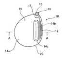
도 1A는 본 발명의 중공 골프 클럽 헤드의 한 가지 실시형태인 중공 골프 클 럽 헤드의 개략을 도시하는 정면도이고, 도 1B는 도 1A에 도시한 골프 클럽 헤드의 페이스부측에서 본 측면도이고, 도 1C는 도 1A에 도시한 골프 클럽 헤드의 솔부측에서 본 저면도이다.FIG. 1A is a front view showing an outline of a hollow golf club head which is one embodiment of the hollow golf club head of the present invention, FIG. 1B is a side view seen from the face side of the golf club head shown in FIG. 1A, and FIG. 1C Is a bottom view seen from the sole side of the golf club head shown in FIG. 1A.
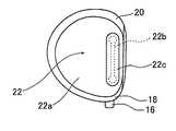
도 2는 도 1A에 도시한 A-A선을 따라 절단된 골프 클럽 헤드의 A-A 화살표에서 본 단면도이다.FIG. 2 is a cross-sectional view taken from the arrow A-A of the golf club head cut along the line A-A shown in FIG. 1A.
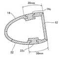
도 3A 및 도 B는 절결부가 설치되는 토우부와 힐부의 범위를 설명하는 도면이다.3A and B are views for explaining the range of the toe part and the heel part in which the cutouts are installed.
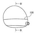
도 4A는 본 발명의 중공 골프 클럽 헤드의 한 가지 실시형태인 중공 골프 클럽 헤드의 힐측에서 본 측면도이고, 도 4B는 도 4A에 도시한 골프 클럽 헤드의 크라운측에서 본 상면도이고, 도 4C는 도 4A에 도시한 골프 클럽 헤드의 페이스측에서 본 정면도이다.4A is a side view as seen from the heel side of the hollow golf club head, which is one embodiment of the hollow golf club head of the present invention, FIG. 4B is a top view as seen from the crown side of the golf club head shown in FIG. 4A, and FIG. 4C is It is a front view seen from the face side of the golf club head shown in FIG. 4A.
도 5는 도 4B에 도시한 B-B선을 따라 절단된 골프 클럽 헤드의 B-B 화살표 방향에서 본 단면도이다.FIG. 5 is a sectional view seen from the direction of arrow B-B of the golf club head cut along the line B-B shown in FIG. 4B.
도 6A는 본 발명의 중공 골프 클럽 헤드의 한 가지 실시형태인 중공 골프 클럽 헤드의 힐측에서 본 측면도이고, 도 6B는 도 6A에 도시한 골프 클럽 헤드의 크라운측에서 본 상면도이고, 도 6C는 도 6A에 도시한 골프 클럽 헤드의 페이스측에서 본 정면도이다.Fig. 6A is a side view seen from the heel side of the hollow golf club head which is one embodiment of the hollow golf club head of the present invention, Fig. 6B is a top view seen from the crown side of the golf club head shown in Fig. 6A, and Fig. 6C is It is the front view seen from the face side of the golf club head shown in FIG. 6A.
도 7은 도 6B에 도시한 C-C선을 따라 절단된 골프 클럽 헤드의 C-C 화살표 방향에서 본 단면도이다.FIG. 7 is a sectional view seen from the direction of arrow C-C of the golf club head cut along the line C-C shown in FIG. 6B.
도 8은 적층된 복합재료의 배향각을 설명하는 설명도이다.It is explanatory drawing explaining the orientation angle of the laminated composite material.
도 9는 도 4에 도시한 골프 클럽 헤드의 두께를 설명하는 설명도이다.9 is an explanatory diagram for explaining the thickness of the golf club head shown in FIG. 4.
도 10A는 본 발명의 중공 골프 클럽 헤드의 한 가지 실시형태인 중공 골프 클럽 헤드의 힐측에서 본 측면도이고, 도 10B는 도 10A에 도시한 골프 클럽 헤드의 크라운측에서 본 상면도이고, 도 10C는 도 10A에 도시한 골프 클럽 헤드의 페이스측에서 본 정면도이다.Fig. 10A is a side view seen from the heel side of the hollow golf club head which is one embodiment of the hollow golf club head of the present invention, Fig. 10B is a top view seen from the crown side of the golf club head shown in Fig. 10A, and Fig. 10C is It is a front view seen from the face side of the golf club head shown to FIG. 10A.
도 11은 도 10B에 도시한 E-E선을 따라 절단된 골프 클럽 헤드의 E-E 화살표 방향에서 본 단면도이다.FIG. 11 is a sectional view seen from the direction of the arrow E-E of the golf club head cut along the line E-E shown in FIG. 10B.
이하, 본 발명의 중공 골프 클럽 헤드에 관해서, 첨부된 도면에 도시된 적합한 가지 실시형태를 기초로 상세하게 설명한다.EMBODIMENT OF THE INVENTION Hereinafter, the hollow golf club head of this invention is described in detail based on the suitable branch embodiment shown by an accompanying drawing.
[제1 실시형태][First Embodiment]
도 1A는 본 발명의 중공 골프 클럽 헤드의 제1 실시형태인 중공 골프 클럽 헤드(이하, 간단하게 골프 클럽 헤드라고 한다)(10)의 개략을 나타내는 정면도이고, 도 1B는 골프 클럽 헤드(10)의 페이스부측에서 본 측면도이다. 도 1C는 골프 클럽 헤드(10)의 솔부측에서 본 저면도이다.FIG. 1A is a front view schematically showing a hollow golf club head (hereinafter simply referred to as a golf club head) 10 as a first embodiment of the hollow golf club head of the present invention, and FIG. 1B is a
골프 클럽 헤드(10)는, 골프공을 타격하는 금속 재료로 이루어진 타격면을 갖는 페이스부(12), 골프 클럽 헤드(10)의 상면을 형성하는 크라운부(14), 골프 클럽 샤프트가 삽입되는 샤프트 삽입공(15)을 갖는 넥부(16) 및 크라운부(14)의 가장 자리를 따라 접속한 사이드부로서, 넥부(16)측에 위치하는 힐부(18), 페이스부(12)를 끼우고 넥부(16)의 반대측에 위치하는 토우부(20), 힐부(18) 및 토우부(20)의 가장자리를 따라 접속되고 크라운부(14)와 대향하도록 배치된 골프 클럽 헤드(10)의 바닥면을 이루는 솔부(22)로 구성된다.The
크라운부(14), 힐부(18), 토우부(20) 및 솔부(22)는 페이스부(12)와 인접하고 있다.The
여기서, 힐부(18)와 토우부(20)는 1개 이상의 사이드 부재에 의해서 사이드부가 형성되어 있다.Here, the
또한, 페이스부(12), 크라운부(14), 솔부(22) 및 사이드부 각 부분은, 각각 대응하는 부재가 제작된 후 용접이나 접착제 등에 의한 접합에 의해 일체적으로 되어 형성된 것이라도 양호하거나, 페이스부(12), 크라운부(14), 솔부(22) 및 사이드부의 2개 이상의 부분에 대응하는 부재가 일체적으로 제작된 후 용접이나 접착제 등에 의한 접합에 의해 일체적으로 되어 형성된 것이라도 양호하다. 또한, 크라운부(14) 및 솔부(22) 각각은, 부재의 일부분이 나머지 부분과 따로 따로 제작된 후에 용접이나 접착제 등에 의한 접합에 의해 일체적으로 되어 형성된 것이라도 양호하다.In addition, each of the
적어도, 골프 클럽 헤드(10)에 있어서 제작방법은 특별히 한정되지 않는다.At least, the manufacturing method in the
페이스부(12), 힐부(18) 및 토우부(20)는 티탄 합금, 마그네슘 합금, 스테인레스 합금 및 알루미늄 합금으로부터 선택된 합금으로 구성되어 있다.The
크라운부(14)는 티탄 합금, 마그네슘 합금, 스테인레스 합금 및 알루미늄 합 금으로부터 선택된 합금 재료로 구성되며, 슬릿상 절결부(14b)를 갖는 크라운 본체부재(14a)와 당해 슬릿상 절결부(14b)에 계합하여, 절결부(14b) 주위의 크라운 본체부재(14a)와 접착되어 절결부(14b)를 폐색하는 폐색부재(14c)로 구성된다.The
또한, 솔부(22)는 티탄 합금, 마그네슘 합금, 스테인레스 합금 및 알루미늄 합금 등으로부터 선택된 합금으로 구성된 솔 본체부재(22a)와 당해 솔 본체부재(22a)에 설치된 슬릿상 절결부(22b)에 계합하여, 절결부(22b) 주위의 솔 본체부재(22a)와 접착되어 절결부(22b)를 폐색하는 폐색부재(22c)로 구성된다.In addition, the
또한, 절결부(14b, 22b)는 모두 절결부(14b, 22b)의 양 말단의 절결폭을 크게하여 여분의 응력이 집중되지 않도록 구성되어 있다.In addition, the
폐색부재(14c, 22c)는 탄소섬유, 유리섬유, 아라미드 섬유 등의 강화섬유를 에폭시 수지, 불포화 폴리에스테르 수지, 비닐에스테르 수지 등의 매트릭스 수지에 함침시켜 형성된 섬유 강화 플라스틱 재료로 구성되며, 소정 방향으로 섬유를 배향시킨 섬유 강화 플라스틱 재료를 층상으로 복수 적층하여 형성된 복합재료로 이루어져 있다. 또한, 강화섬유는, 탄성율이 27 ×103(kg-f/mm2) 미만인 것이 바람직하다.The blocking
또한, 폐색부재(14c, 22c)는, 페이스부(12)에 사용되는 금속 재료의 굴곡 강성보다도 낮은 재료가 사용되고, 바람직하게는 영율(young's modulus)이 낮은 재료가 사용된다. 여기서, 굴곡 강성은 페이스부의 타격면에 수직인 평면에서 크라운부를 절단하였을 때, 크라운부의 절단선을 따르는 방향을 따라 면외 방향으로 굴곡 되었을 때의 굴곡 강성이다.As the blocking
도 2는, 도 1A에 도시한 A-A선을 따라 절단된 골프 클럽 헤드(10)의 A-A 화살표 방향에서 본 단면도이다.FIG. 2 is a sectional view seen from the arrow A-A of the
폐색부재(14c)는, 페이스부(12)와 인접하는 크라운부(14)의 가장자리로부터 30mm 범위내의 크라운부(14)의 영역에 페이스부(12)와 인접하는 크라운부(14)의 가장자리를 따라 배치되어 있고, 폐색부재(22c)는 페이스부(12)와 인접하는 솔부(22)의 가장자리로부터 30mm 범위내의 솔부(22) 영역에 페이스부(12)와 인접하는 솔부(22)의 가장자리를 따라 배치되어 있다.The
페이스부(12)와 인접하는 가장자리를 따라 당해 가장자리로부터 30mm 이내의 영역에 폐색부재(14c, 22c)를 설치하는 것은, 페이스부(12)의 충격시의 변형을 효과적으로 크게 하여, 타격되는 골프공의 반발계수를 높여 비거리를 상승시킬 수 있기 때문이다. 즉, 이러한 구성으로 함으로써, 후술하는 실시예에 나타내는 바와 같이, 페이스부(12)의 두께를 얇게 하지 않고 타격된 골프공의 반발계수를 높일 수 있어 골프공의 비거리가 향상되는 것과 같은 효과를 발휘한다. 또한, 페이스부(12)와 인접하는 크라운부(14) 및 솔부(22)의 가장자리를 따라 배치되는 폐색부재(14c, 22c)의 길이는 20 내지 50mm로 하는 것이 위의 효과를 효과적으로 발휘하는 점에서 바람직하다.Providing the blocking
또한, 위의 실시형태에서는, 크라운부(14)와 솔부(22)의 절결부(14b, 22b)의 폐색부재(14c, 22c)에 섬유 강화 플라스틱 재료를 사용하는 것이지만, 폐색부재로서, 페이스부(12)에 사용되는 금속 재료와 상이한 이종 금속 재료가 사용될 수도 있다. 이러한 경우, 크라운부(14)와 솔부(22) 중의 어느 한쪽에 섬유 강화 플라스틱이, 다른쪽에 이종 금속 재료가 사용될 수도 있다.In the above embodiment, the fiber-reinforced plastic material is used for the
이러한 경우에 있어서도, 사용되는 이종 금속 재료는 페이스부(12)의 금속 재료와 비교하여 굴곡 강성이 낮은 재료, 바람직하게는 영율이 낮은 재료가 사용된다.Also in this case, as the dissimilar metal material to be used, a material having a low bending rigidity, preferably a material having a low Young's modulus, is used as compared with the metal material of the
이종 금속 재료란, 단체 금속의 경우, 종류가 상이한 금속인 이외에, 합금의 경우는, 비교하는 합금 사이에서 공통하는 원소의 조성 비율 중 작은 쪽의 값을 취출하여 합계하였을 때의 값이 20% 미만인 경우를 말한다. 예를 들면, 6-4 티탄 합금(Ti:Al:V=90:6:4)과 15-5-3 티탄 합금(Ti:Mo:Zr:Al=77:15:5:3)을 비교하는 경우, 합계치가 80%(=77+3)로 되기 때문에, 6-4 티탄 합금과 15-5-3 티탄 합금은 이종 금속 재료라고는 하지 않는다. 한편, 마그네슘이 80% 이상인 조성 비율을 갖는 마그네슘 합금과 6-4 티탄 합금은 이종 금속 재료라고 할 수 있다.In the case of a single metal, in the case of an alloy, in the case of an alloy, in the case of an alloy, the value of the less than 20% of the composition ratio of the common elements among the alloys compared is less than 20%, Say the case. For example, a 6-4 titanium alloy (Ti: Al: V = 90: 6: 4) and a 15-5-3 titanium alloy (Ti: Mo: Zr: Al = 77: 15: 5: 3) are compared. In this case, since the total value is 80% (= 77 + 3), the 6-4 titanium alloy and the 15-5-3 titanium alloy are not called different metal materials. On the other hand, a magnesium alloy and a 6-4 titanium alloy having a composition ratio of 80% or more magnesium can be said to be a dissimilar metal material.
또한, 크라운부(14) 및 솔부(22) 이외에, 힐부(18) 및 토우부(20)에 절결부가 설치되고, 이러한 절결부를 폐색하도록 페이스부(12)에 사용되는 금속 재료와 상이한 이종 금속 재료나 섬유 강화 플라스틱 재료가 사용될 수도 있다. 이러한 경우, 도 3A 및 도 B에 도시한 바와 같이, 페이스부(12)와 인접한 가장자리로부터 토우부(20)나 힐부(18)의 윤곽을 따르는 30mm 범위내의 영역에 절결부가 페이스부(12)와 인접한 가장자리를 따라 설치됨으로써, 힐부(18) 및 토우부(20) 부분은 페이스부(12)와 인접한 말단으로부터 30mm 범위내에 이러한 인접 말단을 따라 절결부를 가지며, 이러한 절결부를 폐색하는 폐색부재가 설치된다. 이러한 경우, 페이스 부(12)와 인접한 가장자리를 따라 배치되는 폐색부재의 길이는 10 내지 20mm로 하는 것이 바람직하다.In addition to the
본 발명에 있어서는, 섬유 강화 플라스틱 재료 및 페이스부(12)에 사용되는 금속 재료와 상이한 이종 금속 재료가 크라운부, 솔부, 힐부 및 토우부 중의 2개 이상의 부분에 사용된다.In the present invention, a dissimilar metal material different from the metal material used for the fiber reinforced plastic material and the
또한, 페이스부(12)와 인접하는 가장자리란, 페이스부(12) 중앙 부근의 곡률 반경과 비교하여 절반 이하로 곡률 반경이 작아진 부위이며, 실질적으로 곡률 반경이 대략 불연속적으로 변화하는 부위이다.The edge adjacent to the
이와 같이, 본 발명의 중공 골프 클럽 헤드는, 이러한 골프 클럽 헤드의 크라운부, 힐부, 솔부 및 토우부 중의 2개 이상의 부분이 골프 클럽 헤드의 페이스부와 인접하는 말단을 따르는 인접 말단으로부터 30mm 범위내의 영역에 페이스부에 사용되는 금속 재료와 상이한 이종 금속 재료 및 섬유 강화 플라스틱 재료 중의 어느 하나가 설치되기 때문에, 페이스부 이외에 크라운부, 힐부, 솔부 및 토우부 중의 2개 이상의 부분이 골프공의 충격에 대하여 변형되기 쉬운 구조가 되며, 페이스부를 종래와 비교하여 크게 변형시킴으로써, 타격되는 골프공의 반발계수를 높여 골프공의 초속도를 높여 비거리를 향상시킬 수 있다.As such, the hollow golf club head of the present invention has a range of 30 mm from an adjacent end along which the two or more portions of the crown, heel, sole and toe of the golf club head are adjacent to the face of the golf club head. Since at least one of a dissimilar metal material and a fiber-reinforced plastic material different from the metal material used for the face portion is provided in the region, at least two portions of the crown portion, the heel portion, the sole portion, and the toe portion, in addition to the face portion, are affected by the impact of the golf ball. It becomes a structure that is easy to deform, and by greatly deforming the face portion compared to the conventional, it is possible to increase the repulsion coefficient of the golf ball to be hit to increase the initial speed of the golf ball to improve the distance.
위의 실시형태에 있어서의 골프 클럽 헤드(10)의 폐색부재(14c, 22c)를 크라운부(14)에 설치하는 방법은 특별히 제한되지 않으며, 어떠한 방법에 의해서도 양호하다. 예를 들면, 크라운 본체부재나 솔 부재 등의 본체부재를 절결부를 경계로 하여 2개의 본체 부분 부재로 나누어 제작하고, 제작된 2개의 본체 부분 부재에 의 해서 형성되는 절결부의 위치에 폐색부재를 배치한 후, 2개의 본체 부분 부재로 폐색부재를 끼우면서 접착제로 폐색부재와 폐색부재 주위의 본체 부분 부재를 접합하는 동시에, 2개의 본체 부분 부재를 용접이나 접착제로 접합하면 양호하다.The method of providing the
본 발명의 중공 골프 클럽 헤드를 사용하여 골프공의 비거리를 측정하여, 본 발명의 효과를 조사하였다.The distance of the golf ball was measured using the hollow golf club head of the present invention to investigate the effect of the present invention.
본 발명의 중공 골프 클럽 헤드로서, 도 1A 내지 도 C에 도시된 골프 클럽 헤드를 제작하였다. 크라운부(14)와 솔부(22)의 폐색부재(14c, 22c)에 탄소섬유 강화 플라스틱 재료로 이루어진 적층 복합재료를 사용하여 페이스부에 15-5-3 티탄 합금으로 이루어진 부재를, 그 밖의 부분에 6-4 티탄 합금으로 이루어진 부재를 사용한 골프 클럽 헤드를 제작하였다(실시예 1).As the hollow golf club head of the present invention, the golf club head shown in Figs. 1A to C was produced. A member made of a 15-5-3 titanium alloy on the face part using a laminated composite material made of a carbon fiber reinforced plastic material on the
탄소섬유 강화 플라스틱 재료는, 탄소섬유의 탄성율이 27 ×103(kg-f/mm2)미만인 것을 사용하였다. 또한, 복합재료의 구성은, 배향각을 ±45도로 교대로 적층한 4층 구성의 복합재료로 하였다. 여기서, 배향각은 골프공의 타출방향을 기준방향으로 한 탄소섬유의 배향방향이다.Carbon fiber reinforced plastic materials have an elastic modulus of 27 × 103 (kg-f / mm2 ) Less than was used. In addition, the structure of the composite material was made into the composite material of the 4-layered structure which laminated | stacked the orientation angle alternately +/- 45 degree. Here, the orientation angle is the orientation direction of the carbon fiber with the golf ball outing direction as the reference direction.
또한, 크라운부(14), 힐부(18), 토우부(20) 및 솔부(22)에 페이스부(12)와 인접 말단으로부터 30mm 범위내의 영역에 이러한 인접 말단을 따라 절결부를 설치하고, 실시예 1과 동일한 복합재료를 절결부의 폐색부재로 하며, 그 밖의 부분에 실시예 1에 사용한 티탄 합금과 동일한 티탄 합금을 사용한 골프 클럽 헤드를 제작하였다(실시예 2).In addition, a cutout is provided along the adjacent end in the region of the
또한, 도 1A 내지 도 C에 도시한 크라운부(14)와 솔부(22)의 폐색부재(14c, 22c)에 마그네슘의 조성 비율이 80% 이상인 마그네슘 합금을 사용하고, 그 밖의 부분에 실시예 1에 사용한 티탄 합금과 동일한 티탄 합금을 사용한 골프 클럽 헤드를 제작하였다(실시예 3). 마그네슘 합금은 티탄 합금과 이종 금속 재료의 관계에 있는 것을 사용하였다. In addition, the magnesium alloy whose composition ratio of magnesium is 80% or more is used for the
또한, 크라운부(14), 힐부(18), 토우부(20) 및 솔부(22)에, 페이스부(12)와 인접 말단으로부터 30mm 범위내의 영역에 이러한 인접 말단을 따라 절결부를 설치하고, 실시예 3과 동일한 마그네슘 합금을 절결부의 폐색부재로 하고, 그 밖의 부분에 실시예 1에 사용한 티탄 합금과 동일한 티탄 합금을 사용한 골프 클럽 헤드를 제작하였다(실시예 4).In addition, in the
또한, 실시예 1 내지 4에 사용하는 폐색부재에 있어서의 굴곡 강성은 어느 것이나 페이스부에서의 굴곡 강성과 비교하여 값을 낮아지도록 하였다.In addition, the bending stiffness in the blocking member used in Examples 1 to 4 was to be lowered in comparison with the bending stiffness at the face portion.
또한, 비교예로서, 실시예 1 내지 4에 있어서 사용한 티탄 합금과 동일한 티탄 합금으로 구성한 단일 합금으로 이루어진 중공 골프 클럽 헤드를 제조하였다.Moreover, as a comparative example, the hollow golf club head which consists of a single alloy comprised from the same titanium alloy as the titanium alloy used in Examples 1-4 was manufactured.
제작한 골프 클럽 헤드에 골프 클럽 샤프트를 장착하고, 추가로 이러한 골프 클럽 샤프트에 그립부를 설치하여 골프 클럽을 제작하였다.A golf club was manufactured by attaching a golf club shaft to the produced golf club head and additionally installing a grip on the golf club shaft.
비거리 측정은, 미야마에(Miyamae Co., Ltd.)가 제조한 미야 숏트 로보(Miya Shot Robo) IV에 의해, 헤드 스피드 4O(m/초)의 조건하에, 제작된 골프 클럽을 사용하여 골프공을 시험 타격하여 실시하였다.The flying distance was measured using a golf club produced by Miya Shot Robo IV manufactured by Miyamae Co., Ltd. under conditions of head speed 40 (m / sec). Was carried out by a test blow.
비거리는, 비교예를 100으로 하여 지수에 의해 정리하여 표 1에 기재한 결과 가 수득되었다. 또한, 지수가 클수록 골프공의 비거리가 신장된 것을 나타낸다.As for the flying distance, the result shown in Table 1 was summarized by the index made the comparative example 100. In addition, the larger the index, the longer the distance of the golf ball.
표 1에 있어서의「FRP」는 탄소섬유 강화 플라스틱을 의미한다."FRP" in Table 1 means a carbon fiber reinforced plastic.
표 1로부터 알 수 있는 바와 같이, 실시예 1 내지 4의 골프 클럽 헤드를 사용한 골프 클럽은 어느 것이나 비교예와 비교하여 비거리가 신장되고 있는 것을 알 수 있었다.As can be seen from Table 1, it was found that the golf clubs using the golf club heads of Examples 1 to 4 were each extended in a distance compared with the comparative example.
[제2 실시형태]Second Embodiment
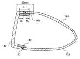
도 4A는, 본 발명의 중공 골프 클럽 헤드의 제2 실시형태인 중공 골프 클럽 헤드(이하, 간단하게 골프 클럽 헤드(110)라고 한다)의 힐측에서 본 측면도이고, 도 4B는, 도 4A에 도시한 골프 클럽 헤드의 크라운측에서 본 상면도이고, 도 4C는, 도 4A에 도시한 골프 클럽 헤드의 페이스측에서 본 정면도이다.FIG. 4A is a side view seen from the heel side of the hollow golf club head (hereinafter, simply referred to as golf club head 110) which is the second embodiment of the hollow golf club head of the present invention, and FIG. 4B is shown in FIG. 4A. It is a top view seen from the crown side of one golf club head, and FIG. 4C is a front view seen from the face side of the golf club head shown in FIG. 4A.
골프 클럽 헤드(110)는, 골프공을 타격하는 금속 재료로 이루어진 타격면을 갖는 페이스부(112), 골프 클럽 헤드(110)의 상면을 형성하는 크라운부(114), 골프 클럽 샤프트가 삽입되는 샤프트 삽입공(115)을 갖는 넥부(116) 및 크라운부(114)의 가장자리를 따라 접속한 사이드부로서, 넥부(116)측에 위치하는 힐부(118), 페이스부(112)를 끼우고 넥부(116)의 반대측에 위치하는 토우부(120), 힐부(118) 및 토우부(120)의 가장자리를 따라 접속되며, 크라운부(114)와 대향하도록 배치된 골프 클럽 헤드(110)의 바닥면을 이루는 솔부(122)로 구성된다.The
힐부(118), 토우부(120), 솔부(122) 및 크라운부(114)는 페이스부(112)와 인접하고 있다.The
여기서, 힐부(118)와 토우부(120)는, 1개 이상의 사이드 부재에 의해서 사이드부가 형성되어 있다. 페이스부(112), 힐부(118) 및 토우부(120)는 티탄 합금으로 이루어지지만, 티탄 합금, 마그네슘 합금, 스테인레스 합금 및 알루미늄 합금으로부터 선택된 합금으로 구성되어도 양호하다.Here, the
크라운부(114) 및 솔부(122)는 티탄 합금으로 이루어지지만, 티탄 합금, 마그네슘 합금, 스테인레스 합금 및 알루미늄 합금으로부터 선택된 합금 재료나 섬유 강화 플라스틱(FRP)으로 구성될 수 있다.
크라운부, 힐부, 솔부 및 토우부 중의 2개 이상의 부분이 페이스측과 백측으로 각각 분할된다.Two or more portions of the crown portion, the heel portion, the sole portion, and the toe portion are divided into the face side and the back side, respectively.
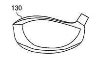
본 실시형태에서는, 2개의 부분으로서 크라운부 및 솔부를 선택하여, 도 4에 도시한 바와 같이, 크라운부(114)는 수지로 이루어진 접합선(130)을 경계로 하여 페이스측 크라운부와 백측 크라운부로 분할되고, 솔부는 수지로 이루어진 접합선(132)을 경계로 하여 페이스측 솔부와 백측 솔부로 분할된다. 이러한 접합선(130, 132)은, 페이스부(112)와 인접 말단을 따라 당해 인접 말단으로부터 30mm 범위내에 있다. 또한, 접합선(130, 132) 전체가, 페이스부(112)와 인접 말단을 따라 당해 인접 말단으로부터 30mm의 범위에 포함되어 있지 않아도 양호하며, 두 군데 이상 존재하는 접합선의 전체 길이가 40mm 이상이면 양호하다.In this embodiment, the crown part and the sole part are selected as two parts, and as shown in FIG. 4, the
접합선을 따라 2분할된 크라운부(114) 및 솔부(122)의 각각의 부재는 접착제에 의해, 도 5A(또는 도 5B)에 도시된 접합부(140)(또는 144) 및 (142)와 접착되어 페이스측과 백측이 일체가 되어 형성되어 있다. 접합부는 탄소섬유를 강화섬유로 하여 매트릭스 수지에 함침시켜 형성한 탄소섬유 강화 플라스틱 재료로 구성된다. 또한, 접합부는 탄소섬유, 유리섬유, 아라미드 섬유 등의 강화섬유를 에폭시 수지, 불포화 폴리에스테르 수지, 비닐에스테르 수지 등의 매트릭스 수지에 함침시켜 형성된 섬유 강화 플라스틱 재료로 구성될 수 있다.Each member of the
본 실시형태에서는, 크라운부 및 솔부가 각각 2분할되어 있고, 분할된 부재는 접합부를 개재시켜 일체로 되어 있기 때문에, 골프공의 충격에 대하여 변형되기 쉬운 구조로 이루어져 있다. 따라서, 페이스부를 종래와 비교하여 크게 변형시킴으로써, 타격되는 골프공의 반발계수를 높여 골프공의 초속도를 높여 비거리를 향상시킬 수 있다.In the present embodiment, the crown portion and the sole portion are divided into two, and since the divided members are integrated through the joining portion, they have a structure that is easily deformed against the impact of the golf ball. Therefore, by greatly deforming the face portion as compared with the conventional, it is possible to increase the repulsion coefficient of the golf ball to be hit to increase the initial speed of the golf ball to improve the flying distance.
도 5A는 도 4B에 도시한 B-B선을 따라 절단된 골프 클럽 헤드(110)의 B-B 화살표 방향에서 본 단면도이다.FIG. 5A is a sectional view seen from the direction of arrow B-B of the
2분할된 크라운부 및 솔부의 각각의 부분 중에서 페이스측을 구성하는 부재를 페이스측 부재(112)라고 하며, 백측을 구성하는 부재를 백측 부재(114, 122)라고 한다. 도 5A 및 도 B에 도시한 실시형태에서는, 페이스측 부재와 백측 부재는 모두 티탄 합금으로 구성되며, 접합선(140, 132)을 따라 떨어져 있지만, 이러한 접합선은 페이스측 부재와 솔측 부재의 간극을 메우는 수지이다. 그러나, 접합선은 여기에 한정되지 않으며, 예를 들면, 섬유 강화 플라스틱 재료(FRP)를 사용하여 간극을 메워도 양호하다. 또한, 이러한 간극의 폭은 1mm로 하지만, 골프공의 충격에 대하여 변형되기 쉬운 구조로 하기 위해서 설치되어 있어 그 폭은 적절하게 설정할 수 있다.The members constituting the face side among the divided portions of the crown portion and the sole portion are referred to as the
접합부(140, 142)는 각각 1개의 접합 부재에 의해서 구성되어 있고, 탄소섬유 강화 플라스틱으로 이루어진다. 접합부(140)의 전체 길이를 F1로 하고, 페이스측 크라운부와 접착하는 부분의 길이를 G1으로 하며, 백측 크라운부와 접착하는 부분의 길이를 H1으로 하면, 접합부의 전체 길이 F1은 15 내지 80mm이면 양호하다. 또한, 페이스측 접합부 길이 G1은 8 내지 30mm인 것이 바람직하고, 12 내지 20mm인 것이 보다 바람직하다. 백측 접합부 길이 H1은 5 내지 40mm인 것이 바람직하고, 5 내지 30mm인 것이 보다 바람직하고, 5 내지 20mm인 것이 더욱 바람직하다.The joining
또한, 접합부(142)의 전체 길이나 접합 길이는 접합부(140)와 동일하다.In addition, the full length of the
도 5B는, 도 4B에 도시한 B-B선을 따라 절단된 골프 클럽 헤드(110)의 B-B 화살표 방향에서 본 단면도이고, 접합부(140)의 변형예를 도시한다. 도 5B에서는, 페이스측과 접착하는 접합부(144)의 일부분이 만곡하여 페이스부(112)와 접착되어 있다. 이와 같이 페이스측의 접합부는 크라운부 뿐만 아니라, 페이스부와 접하더라도 양호하다. 마찬가지로 솔부(142)도 페이스부에 접하더라도 양호하다. 단, 이러한 경우에도, 접합부의 전체 길이 F2는 15 내지 80mm이고, 바람직하게는 5 내지 20mm이다.FIG. 5B is a sectional view seen from the direction of the BB arrow of the
[제3 실시형태][Third Embodiment]
도 6A는 본 발명의 중공 골프 클럽 헤드의 제3 실시형태인 중공 골프 클럽 헤드(이하, 골프 클럽 헤드(160)라고 한다)의 힐측에서 본 측면도이고, 도 6B는 도 6A에 도시한 골프 클럽 헤드의 크라운측에서 본 상면도이고, 도 6C는 도 6A에 도시한 골프 클럽 헤드의 페이스측에서 본 정면도이다. Fig. 6A is a side view seen from the heel side of a hollow golf club head (hereinafter referred to as golf club head 160) as a third embodiment of the hollow golf club head of the present invention, and Fig. 6B is a golf club head shown in Fig. 6A. Fig. 6C is a front view seen from the face side of the golf club head shown in Fig. 6A.
제2 실시형태에서는 크라운부(114)와 솔부(122)에 페이스부(112)와 동일한 금속 재료(티탄 합금)를 사용하였지만, 제3 실시형태에서는 페이스부와는 상이한 이종 금속 재료를 사용한다. 또한, 제2 실시형태와 동일한 부분에는 동일한 부호를 붙이고 설명을 생략한다.In the second embodiment, the same metallic material (titanium alloy) as the
이종 금속 재료란, 단체 금속의 경우, 종류가 상이한 금속인 이외에, 합금의 경우는 비교하는 합금 사이에서 공통하는 원소의 조성 비율 중 작은 쪽의 값을 취출하여 합계하였을 때의 값이 20% 미만인 경우를 말한다.In the case of a single metal, in the case of a single metal, in the case of an alloy, in the case of an alloy, in the case of an alloy, when the value of the smaller one of the composition ratio of the elements common between alloys compared is taken out and summed is less than 20%, Say.
본 발명의 중공 골프 클럽 헤드는, 크라운부(124), 힐부(118), 솔부(126) 및 토우부(120) 중의 2개 이상의 부분이, 페이스부와 인접하는 말단을 따라 당해 인접 말단으로부터 30mm 범위내의 영역에서 2분할되어 페이스부(112)까지 연재하는 제1 부재와 그 밖의 제2 부재로 각각 구성된다.In the hollow golf club head of the present invention, two or more portions of the
본 실시형태에서는, 2분할되는 부분으로서 크라운부(124) 및 솔부(126)를 선택하고, 도 7에 도시한 바와 같이, 크라운부(124)는 수지로 이루어진 접합선(130)을 경계로 하여 페이스측 크라운부와 백측 크라운부로 분할되며, 솔부(126)는 수지로 이루어진 접합선(132)을 경계로 하여 페이스측 솔부와 백측 솔부로 분할된다.In this embodiment, the
또한, 도 7A 및 도 B에 도시되어 있는 바와 같이, 이러한 제1 부재 및 제2 부재와 겹쳐져 접합되는 접합 부재(140)(또는 144) 및 (142)에 의해 접합부가 형성되며, 이러한 접합 부재는 섬유 강화 플라스틱으로 이루어진다. 이로 인해, 본 발명의 중공 골프 클럽 헤드는 골프공의 충격에 대하여 변형되기 쉬운 구조가 되며, 페이스부를 종래와 비교하여 크게 변형시킴으로써, 타격되는 골프공의 반발계수를 높여 골프공의 초속도를 높여 비거리를 향상시킬 수 있다.In addition, as shown in Figs. 7A and B, the joining portion is formed by the joining members 140 (or 144 and 142) overlapping and joining with the first member and the second member. It is made of fiber reinforced plastic. Therefore, the hollow golf club head of the present invention is a structure that is easy to be deformed against the impact of the golf ball, by greatly deforming the face portion compared with the conventional, to increase the repulsion coefficient of the golf ball to be hit to increase the initial speed of the golf ball to fly distance Can improve.
도 7A는, 도 6B에 도시한 C-C선을 따라 절단된 골프 클럽 헤드의 C-C 화살표 방향에서 본 단면도이다. 도 5A에 도시한 골프 클럽 헤드(110)에서는, 접합부는 1개의 접합 부재에 의해서 구성되어 있지만, 도 7A에 도시한 골프 클럽 헤드(160)에서는 접합부(140)는 백측 부재(124)의 일부분으로서 구성되며, 탄소섬유 강화 플라스틱으로 이루어진다.FIG. 7A is a sectional view seen from the direction of arrow C-C of the golf club head cut along the line C-C shown in FIG. 6B. In the
도 7B는, 도 6B에 도시한 C-C선을 따라 절단된 골프 클럽 헤드(160)의 C-C 화살표 방향에서 본 단면도이고, 접합부(140)의 변형예를 도시한다. 도 7B에서는, 페이스측과 접착하는 접합부(144)의 일부분이 만곡하여 페이스부와 접착되어 있다. 이와 같이 페이스측의 접합부는 크라운부 뿐만 아니라, 페이스부와 접하더라도 양호하다. 이러한 경우에도, 접합부의 전체 길이 F2는 15 내지 80mm이다. 또한, 솔부(142)도 마찬가지로 페이스부에 접하더라도 양호하다.FIG. 7B is a sectional view seen from the direction of the CC arrow of the
본 발명의 중공 골프 클럽 헤드는, 크라운부, 힐부, 솔부 및 토우부 중의 2개 이상의 부분이, 페이스부와 인접하는 말단을 따라 당해 인접 말단으로부터 30mm 범위내의 영역에서 2분할되고, 페이스부까지 연재하는 제1 부재와 섬유 강화 플라스틱으로 이루어진 제2 부재로 각각 구성된다. 또한, 중공 골프 클럽 헤드의 제2 부재가 제1 부재와 겹쳐져 접합된 접합부가 형성되어 있다. 이로 인해, 본 발명의 중공 골프 클럽 헤드는 골프공의 충격에 대하여 변형되기 쉬운 구조가 되며, 페이스부를 종래와 비교하여 크게 변형시킴으로써, 타격되는 골프공의 반발계수를 높여 골프공의 초속도를 높여 비거리를 향상시킬 수 있다.In the hollow golf club head of the present invention, two or more portions of the crown portion, the heel portion, the sole portion, and the toe portion are divided into two portions in an area within a range of 30 mm from the adjacent end portion along an end portion adjacent to the face portion, and extended to the face portion. It consists of a 1st member and the 2nd member which consists of fiber reinforced plastics, respectively. Moreover, the joining part by which the 2nd member of the hollow golf club head overlapped with the 1st member is formed. Therefore, the hollow golf club head of the present invention is a structure that is easy to be deformed against the impact of the golf ball, by greatly deforming the face portion compared with the conventional, to increase the repulsion coefficient of the golf ball to be hit to increase the initial speed of the golf ball to fly distance Can improve.
본 발명의 중공 골프 클럽 헤드를 사용하여 내구성 및 반발성을 측정하여 본 발명의 효과를 조사하였다.The effects of the present invention were investigated by measuring durability and resilience using the hollow golf club head of the present invention.
본 발명의 중공 골프 클럽 헤드로서, 도 4A 내지 도 4C에 도시한 골프 클럽 헤드를 제작하였다.As the hollow golf club head of the present invention, the golf club head shown in Figs. 4A to 4C was produced.
분할하는 부분으로서, 도 4A 내지 도 4C에 도시한 바와 같이 크라운부 및 솔부를 선택하고, 각각의 제1 부재 및 제2 부재에, 도 5A에 도시한 바와 같이, 티탄 합금(Ti 합금)을 사용하였다. 이러한 티탄 합금은, V가 15중량%, Cr가 3중량%, Al이 3중량%, Sn이 3중량%이고, 잔여부가 Ti로 조성된 것이다. 또한, 제1 부재와 제2 부재의 간극을 수지로 채워 막았다.As the part to be divided, a crown portion and a sole portion are selected as shown in Figs. 4A to 4C, and titanium alloys (Ti alloys) are used for the first and second members, respectively, as shown in Fig. 5A. It was. Such a titanium alloy is 15 weight% of V, 3 weight% of Cr, 3 weight% of Al, and 3 weight% of Sn, and the remainder consists of Ti. In addition, the gap between the first member and the second member was filled with resin to prevent it.
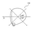
복합부에 탄소섬유 강화 플라스틱 재료(CFRP)가 적층된 복합재료를 사용하였다. 이러한 탄소섬유 강화 플라스틱 재료는, 탄소섬유의 탄성율이 24 ×103(kg-f/mm2)이고, 섬유 밀도가 160g/m2이며, 수지 함량이 38%인 것이다. 또한, 복합재료의 구성은 배향각을 ±45°로 교대로 적층한 6층 구성의 복합재료이다. 여기서, 배향각은, 도 8에 도시한 바와 같이, 골프공의 타출방향 D를 기준방향으로 한 탄소섬유의 배향방향을 말한다.A composite material in which a carbon fiber reinforced plastic material (CFRP) was laminated on the composite part was used. The carbon fiber reinforced plastic material has an elastic modulus of 24 x 103 (kg-f / mm2 ), a fiber density of 160 g / m2 , and a resin content of 38%. In addition, the structure of a composite material is a composite material of 6-layered constitution which alternately laminated | stacked the orientation angle to +/- 45 degrees. Here, as shown in FIG. 8, the orientation angle means the orientation direction of the carbon fiber which made the golf ball the launching direction D the reference direction.
페이스 부재에는 15-5-3 티탄 합금으로 이루어진 부재를 사용하였다.As the face member, a member made of 15-5-3 titanium alloy was used.
또한, 도 9에 도시한 바와 같이, 크라운부 및 솔부의 제1 부재의 두께를 t1로 하고, 복합부의 탄소섬유 강화 플라스틱 재료의 두께를 t2로 하며, 도 5A에 도시한 페이스측 복합부 길이를 G로 하고, 백측 복합 길이를 H로 하며, 표 2에 기재한 바와 같이 설정하여 실험예 1 내지 20을 제작하였다. 또한, 본 발명에 있어서 t1의 두께가 0.5 내지 2.0mm이고, t2의 두께가 0.5 내지 1.5mm인 것이 바람직하고, t1의 두께가 0.8 내지 1.8mm이고, t2의 두께가 0.8 내지 1.2mm인 것이 보다 바람직하다.In addition, as shown in FIG. 9, the thickness of the first member of the crown portion and the sole portion is t1 , the thickness of the carbon fiber reinforced plastic material of the composite portion is t2 , and the face side composite portion shown in FIG. 5A. The length was G, the back side composite length was H, and it set as shown in Table 2, and produced Experimental Examples 1-20. In the present invention, the thickness of t1 is preferably 0.5 to 2.0 mm, the thickness of t2 is 0.5 to 1.5 mm, the thickness of t1 is 0.8 to 1.8 mm, and the thickness of t2 is 0.8 to 1.2. It is more preferable that it is mm.
제1 부재의 두께 t1, 복합부의 탄소섬유 강화 플라스틱 재료의 두께 t2, 페이스측 복합부 길이 G 및 백측 복합 길이 H는, 페이스의 토우, 힐 방향의 폭을 100%로 하고, 그 폭의 중앙에서 ±20%의 범위내의 어느 하나의 단면에 있어서 달성되고 있으면 양호하다. 이러한 폭을 규정함에 있어서, 토우의 말단부는 통상의 어드레스 포지션(normal address position)에 있어서 가장 토우측으로 확장된 지점으로서 규정하고, 힐의 말단부는 통상의 어드레스 포지션에 있어서 기준면에서 위쪽으로 16mm인 지점으로서 규정된다. 단면은 페이스면과 기준면에 대하여 직각인 것이 바람직하다.First and the width of the toe, heel direction of thickness t2, the face side of the composite section length G and the white-side composite length H is, the face of the first thickness t1, the reinforced composite parts of carbon fibers of the member of plastic material to 100%, of the width What is necessary is just to be achieved in any cross section in the range of +/- 20% at the center. In defining this width, the distal end of the toe is defined as the point that extends most to the toe side in the normal address position, and the distal end of the heel is 16 mm upwards from the reference plane in the normal address position. It is defined as It is preferable that the cross section is perpendicular to the face plane and the reference plane.
여기서, 통상의 어드레스 포지션에 설치한다는 것은, 골프 클럽 헤드(1)를 라이 각도(lie angle)에 따라 설치하고, 이때의 골프 클럽 샤프트의 중심축과 골프 클럽 헤드의 페이스부의 리딩 에지(leading edge)가 기준면의 수직 위쪽에서 보아 서로 평행해지도록, 즉 페이스 앵글이 O도가 되도록 설치하는 것을 말한다. 라이 각도에 따르는 설치란, 골프 클럽 헤드의 바닥면을 이루는 솔부의 라운드면과 기준면 사이의 간극이 토우측 및 힐측에서 대략 동일해지도록 설치하는 것을 말한다. 솔부의 라운드면이 불명료한 경우, 페이스면에 형성되어 있는 스코어라인(score line)과 기준면이 평행해지도록 설치해도 양호하다. 또한, 골프 클럽에 있어서, 솔부의 라운드면이 불명료하고, 스코어라인이 직선상이 아닌 등에 의해 기준면과의 평행 여부의 판별이 곤란한 경우는, 라이 각도는, 라이 각도(도)=(100-클럽 길이(인치))로 설정된다. 예를 들면, 44인치의 클럽 길이라면, 라이 각도는 100-44= 56도가 된다.Here, in the normal address position, the
여기서, 클럽 길이는 사단법인 일본 골프용품협회가 규정하는 측정법에 따라 측정한다. 측정기로서는, 가부시키가이샤 카모시타세코죠(Kamoshita Seikoujyo K.K.)가 제조한 클럽 메저(club measurer) Ⅱ를 들 수 있다.Here, the club length is measured according to the measurement method prescribed by the Japan Golf Goods Association. Examples of the measuring device include club measurer II manufactured by Kamoshita Seikoujyo K.K.
실험예 1을 종래예로 하고, 종래예에서는 크라운부 및 솔부는 모두 분할되어 있지 않으며, 티탄 합금만을 사용하고, 이의 두께는 1.7mm이다. 실험예 2 내지 11은, 복합부재 길이 G 및 H를 일정하게 하여 제1 부재의 두께 t1과 복합부의 두께 t2를 변화시키고, 실험예 12 내지 20은 제1 부재의 두께 t1과 복합부재의 두께 t2를 일정하게 하여 복합부재 길이 G 및 H를 변화시켜 설정하였다.Experimental Example 1 is a conventional example, and in the conventional example, both the crown portion and the sole portion are not divided, only titanium alloy is used, and the thickness thereof is 1.7 mm. Experimental Examples 2 to 11 is a composite member length G and the constant H changes the thickness t1 and a composite thickness t2 portion of the first member, Experimental Examples 12 to 20 had a thickness t1 and the composite member of the first member It was set by changing the composite member lengths G and H by keeping the thickness t2 of.
제작한 골프 클럽 헤드에 요코하마고무 가부시키가이샤(THE YOKOHAMA RUBBER CO., LTD)가 제조한 TRX-DUO M40(상품명)용의 골프 클럽 샤프트를 장착시켜 골프 클럽을 제작하고, 이하에 나타내는 시험을 실시하였다. 당해 골프 클럽의 길이는 45인치이다.A golf club was manufactured by attaching a golf club shaft for TRX-DUO M40 (trade name) manufactured by THE YOKOHAMA RUBBER CO., LTD. It was. The golf club is 45 inches long.
또한, 각 시험에서 사용한 골프공으로는, 요코하마고무 가부시키가이샤가 제조한 TRX(상품명) 공을 사용하였다.As the golf ball used in each test, a TRX (brand name) ball manufactured by Yokohama Rubber Co., Ltd. was used.
내구성에 관해서는, 에어 캐논 시험기를 사용하여 골프공을 50m/초의 속도로 실험예의 각 골프 클럽 헤드의 페이스부의 중심부에 충돌시켜 파괴될 때까지의 타구수를 측정하였다. 이러한 경우, 종래예(실험예 1)의 파괴될 때까지의 타구수를 100으로 하고, 각 실시예의 강도를 수치로 나타내었다.As for the durability, the number of hits until the golf ball was broken by colliding with the center of the face portion of each golf club head of the experimental example at a speed of 50 m / sec using an air cannon tester was measured. In this case, the number of shots until breakdown of the conventional example (Experimental Example 1) was set to 100, and the intensity of each example was represented by the numerical value.
반발성에 관해서는, USGA(United States Golf Association: 전미골프협회)에 규정되어 있는 문헌[참조: Procedure for Measuring the Velocity Ratio of a Club Head for Conformance to Rule 4-1e, Appendix Ⅱ Revision 2 February 8, 1999]에 기초하여 측정된 실시예의 반발계수를 사용하여 평가하였다. 이러한 경우, 종래예의 반발계수를 100으로 하고, 각각의 실시예의 반발을 수치로 나타내었다.As for repulsiveness, the procedure for Measuring the Velocity Ratio of a Club Head for Conformance to Rule 4-1e, Appendix II Revision 2 February 8, 1999, as defined in the United States Golf Association (USGA). It was evaluated using the repulsion coefficient of the Example measured based on the]. In this case, the repulsion coefficient of the conventional example was set to 100, and the repulsion of each Example was shown by the numerical value.
하기 표 2에 있어서의 합계점은 내구성과 반발성을 더한 값이고, 종래예(실례1)의 200이 기준치가 되고, 내구성과 반발성이 우수할수록 수치가 커진다.The total point in the following Table 2 is the value which added durability and resilience, 200 is a reference value of a prior art example (Example 1), and a numerical value becomes large, so that durability and resilience are excellent.

표 2에 나타낸 실험예 2 내지 11로부터 알 수 있는 바와 같이, 실험예 2 내지 11는, 어느 것이라도 종래예(실험예 1)와 비교하여 합계점이 큰 것을 알 수 있다. 특히 실험예 2 내지 5의 합계치가 크고, 또한 실험예 3 및 4의 합계치가 최대인 것을 알 수 있다.As can be seen from Experimental Examples 2 to 11 shown in Table 2, it can be seen that in Experimental Examples 2 to 11, the total point is larger than in the conventional example (Experimental Example 1). In particular, it can be seen that the total value of Experimental Examples 2 to 5 was large, and the total value of Experimental Examples 3 and 4 was the largest.
따라서, t1의 두께가 0.5 내지 2.0mm이고, 또한 t2의 두께가 0.5 내지 1.5mm 것이 바람직하고, 더욱 바람직하게는, t1의 두께가 0.8 내지 1.8mm이고, t2의 두께가 0.8 내지 1.2mm인 것이 양호하다고 말할 수 있다.Therefore, it is preferable that the thickness of t1 is 0.5 to 2.0 mm, and the thickness of t2 is 0.5 to 1.5 mm, more preferably, the thickness of t1 is 0.8 to 1.8 mm, and the thickness of t2 is 0.8 to 1.8. It can be said that it is 1.2 mm.
또한, 표 2에 나타낸 실험예 12 내지 20을 t1의 두께 및 t2의 두께가 동일한 실험예 3과 비교하면, 복합부 G의 값이 8mm 이하이고, 또한 복합부 H의 값이 5mm 이하인 실험예 14보다, 복합부 G의 값이 8mm 이상인 실험예 13 및 16이 합계점이 크고, 복합부 G의 값이 8mm 이하이고, 복합부 H의 값이 5mm 이하인 실험예 14보다, 복합부 H의 값이 5mm 이상인 실험예 12 및 15가 합계점이 크고, 복합부 G의 값이 20mm 이상인 실험예 20보다, 복합부 G의 값이 20mm 이하인 실험예 3이 합계점이 크고, 복합부 H의 값이 20mm 이상인 실험예 16보다, 복합부 H의 값이 20mm 이하인 실험예 3이 합계점이 크다.Further, comparing Experimental Examples 12 to 20 shown in Table 2 with Experimental Example3 in which the thickness of t1 and the thickness of t2 were the same, the value of the compound portion G was 8 mm or less, and the value of the compound portion H was 5 mm or less. Experimental example 13 and 16 whose composite part G value is 8 mm or more are larger than Example 14, and the composite part H value is larger than the experimental example 14 whose compound part G value is 8 mm or less, and the value of the composite part H is 5 mm or less. Experimental Examples 12 and 15 having a total point of 5 mm or more have a larger total point, and Experimental Example 3 having a compound part G value of 20 mm or less is larger than Experimental Example 20 having a value of compound part G of 20 mm or more, and a value of the compound part H is 20 mm or more. In Experimental Example 16, Experimental Example 3, in which the value of the composite portion H was 20 mm or less, was larger in total.
페이스측 복합부 길이 G는 8 내지 30mm인 것이 바람직하고, 12 내지 2Omm인 것이 보다 바람직하다.It is preferable that it is 8-30 mm, and, as for face side compound part length G, it is more preferable that it is 12-20 mm.
백측 복합부 길이 H는, 5 내지 40mm인 것이 바람직하고, 5 내지 30mm인 것이 보다 바람직하고, 5 내지 20mm인 것이 바람직하다.It is preferable that the back side composite part length H is 5-40 mm, It is more preferable that it is 5-30 mm, It is preferable that it is 5-20 mm.
[제4 실시형태]Fourth Embodiment
도 10A는, 본 발명의 중공 골프 클럽 헤드(이하, 간단하게 골프 클럽 헤드(210)라고 한다)의 힐측에서 본 측면도이고, 도 10B는, 도 10A에 도시한 골프 클럽 헤드의 크라운측에서 본 상면도이고, 도 10C는, 도 10A에 도시한 골프 클럽 헤드의 페이스측에서 본 정면도이다.Fig. 10A is a side view seen from the heel side of the hollow golf club head (hereinafter simply referred to as golf club head 210) of the present invention, and Fig. 10B is a top view seen from the crown side of the golf club head shown in Fig. 10A. 10C is a front view seen from the face side of the golf club head shown in FIG. 10A.
골프 클럽 헤드(210)는 골프공을 타격하는 금속 재료로 이루어진 타격면을 갖는 페이스부(212), 골프 클럽 헤드(210)의 상면을 형성하는 크라운부(214), 골프 클럽 샤프트가 삽입되는 샤프트 삽입공(215)을 갖는 넥부(216), 크라운부(214)의 가장자리를 따라 접속한 사이드부로서, 넥부(216)측에 위치하는 힐부(218), 페이스부(212)를 끼우고 넥부(216)의 반대측에 위치하는 토우부(220), 힐부(218) 및 토우부(220)의 가장자리를 따라 접속되고, 크라운부(214)와 대향하도록 배치된 골프 클럽 헤드(210)의 바닥면을 이루는 솔부(222)로 구성된다.The
힐부(218), 토우부(220), 솔부(222) 및 크라운부(214)는 페이스부(212)와 인접하고 있다.The
여기서, 힐부(218)와 토우부(220)는 1개 이상의 사이드 부재에 의해 사이드부가 형성되어 있다. 페이스부(212), 힐부(218) 및 토우부(220)는, 티탄 합금으로 이루어지지만, 티탄 합금, 마그네슘 합금, 스테인레스 합금 및 알루미늄 합금으로부터 선택된 합금으로부터 구성될 수 있다.Here, the
크라운부(214) 및 솔부(222)의 일부분은 티탄 합금으로 이루어지지만, 티탄 합금, 마그네슘 합금, 스테인레스 합금 및 알루미늄 합금으로부터 선택된 합금 재료나 섬유 강화 플라스틱(FRP)으로 구성될 수 있다.Portions of
본 실시형태에서는, 2개 이상의 부분으로서 크라운부, 솔부 및 사이드부(힐부(218) 및 토우부(220))를 선택한다. 도 10에 도시한 바와 같이, 크라운부는 페이스측 크라운부와 백측 크라운부로 분할되고 페이스측 크라운부의 한쪽 말단은 페이스부(212)에 인접하고, 페이스부(212)와 인접하는 한쪽 말단으로부터 30mm 범위내에 다른쪽 말단(230)이 있다. 솔부도 크라운부와 마찬가지로 페이스측과 백측으로 분할되며, 한쪽 말단은 페이스면에 인접하고, 페이스면과 인접하는 한쪽 말단으로부터 30mm 범위내에 다른쪽 말단(233)이 있다. 힐부(218) 및 토우부(220)로 이루어진 사이드부도 마찬가지로 페이스측과 백측으로 분할되고, 한쪽 말단은 페이스부(212)에 인접하고, 페이스부(212)와 인접하는 한쪽 말단으로부터 30mm 범위내에 다른쪽 말단(236, 237)이 있다.In this embodiment, a crown part, a sole part, and a side part (heel
도 11A는, 도 10B에 도시한 E-E선을 따라 절단된 골프 클럽 헤드의 E-E 화살표 방향에서 본 단면도이다.FIG. 11A is a sectional view seen from the direction of the arrow E-E of the golf club head cut along the line E-E shown in FIG. 10B.
페이스측 크라운부와 백측 크라운부는 서로 겹쳐져 접합되고, 페이스측 솔부와 백측 솔부는 서로 겹쳐져 접합된다. 또한, 페이스측 힐부와 백측 힐부는 서로 겹쳐져 접합되고, 마찬가지로 페이스측 토우부와 백측 토우부는 서로 겹쳐져 접합된다.The face side crown part and the back side crown part overlap each other and are joined, and the face side sole part and the back side sole part overlap each other and are joined. Moreover, the face side heel part and the back side heel part overlap each other, and similarly, the face side toe part and the back side toe part overlap each other, and are joined.
도 11A에 도시한 접합부분의 길이 G2는, 8 내지 30mm인 것이 바람직하고, 12 내지 20mm인 것이 보다 바람직하다.Fig length G2 of the bonded portion 11A is shown in, it is more preferable that the 8 to 30mm is preferable, and 12 to 20mm.
본 실시형태에서는, 페이스측 크라운부는 페이스부와 동일한 티탄 합금으로 구성되지만, 티탄 합금, 마그네슘 합금, 스테인레스 합금 및 알루미늄 합금으로부터 선택된 합금 재료로 구성될 수 있다. 또한, 백측 크라운부는 탄소섬유 강화 플라스틱으로 구성되지만, 탄소섬유, 유리섬유, 아라미드 섬유 등의 강화섬유를 에폭시 수지, 불포화 폴리에스테르 수지, 비닐에스테르 수지 등의 매트릭스 수지에 함침시켜 형성된 섬유 강화 플라스틱 재료로 구성될 수 있다. 또한, 솔부 및 사이드부(토우부, 힐부)에 관해서도 동일하다.In the present embodiment, the face side crown portion is made of the same titanium alloy as the face portion, but may be made of an alloy material selected from titanium alloy, magnesium alloy, stainless alloy and aluminum alloy. In addition, the back side crown portion is composed of carbon fiber reinforced plastic, but is made of fiber reinforced plastic material formed by impregnating reinforced fibers such as carbon fiber, glass fiber, aramid fiber, and the like with matrix resin such as epoxy resin, unsaturated polyester resin, vinyl ester resin, and the like. Can be configured. The same applies to the sole portion and the side portion (toe portion, heel portion).
페이스측 크라운부와 백측 크라운부, 페이스측 솔부와 백측 솔부, 페이스측사이드부(토우부, 힐부)와 솔측 사이드부(토우부, 힐부)는 서로 접착제나 수지 필름에 의해 접합된다. 이러한 접착제의 종류로서는, 에폭시, 우레탄, 아크릴, 시아노아크릴레이트 수지를 예시할 수 있다. 또한, 수지 필름으로서는, 예를 들면, 폴리우레탄 수지, 나일론 수지, 변성 나일론 수지, 폴리에틸렌 테레프탈레이트 수지, 폴리염화비닐 수지, 폴리카보네이트 수지, 폴리염화비닐리덴 수지, 에틸셀룰로스 수지 및 아세트산셀룰로스 수지 등의 열가소성 수지 필름이 예시된다.The face side crown portion, the back side crown portion, the face side sole portion, the back side sole portion, the face side side portion (toe portion, heel portion) and the sole side side portion (toe portion, heel portion) are joined to each other with an adhesive or a resin film. As a kind of such an adhesive agent, epoxy, urethane, acryl, cyanoacrylate resin can be illustrated. As the resin film, for example, polyurethane resin, nylon resin, modified nylon resin, polyethylene terephthalate resin, polyvinyl chloride resin, polycarbonate resin, polyvinylidene chloride resin, ethyl cellulose resin, cellulose acetate resin, etc. Thermoplastic film is illustrated.
또한, 이러한 수지 필름은, 프리프레그의 매트릭스 수지와의 상용성이 높은 것을 사용하는 것이 바람직하다. 예를 들면, 매트릭스 수지에 에폭시계 수지 등을 사용한 경우에는, 수지 필름으로서는, 폴리우레탄 수지, 변성 나일론 수지 필름 등이 적합하다. 이러한 수지 필름의 두께는, 0.02 내지 0.2mm로 하는 것이 바람직하다.In addition, it is preferable that such a resin film uses the thing with high compatibility with the matrix resin of a prepreg. For example, when an epoxy resin etc. are used for matrix resin, a polyurethane resin, a modified nylon resin film, etc. are suitable as a resin film. It is preferable that the thickness of such a resin film shall be 0.02-0.2 mm.
도 11B는, 도 10B에 도시한 E-E선을 따라 절단된 골프 클럽 헤드(210)의 E-E 화살표 방향에서 본 단면도이고, 접합부의 변형예를 도시한다. 도 11B에서는, 백측 크라운부는 페이스측 크라운부와 접착하는 접합부의 일부분이 만곡하여 페이스부와 접착되어 있다. 이와 같이 백측 크라운부의 접합부는 페이스측 크라운부 뿐만 아니라, 페이스부와 접하더라도 양호하다. 단, 이러한 경우, 페이스측 접합부 길이 G3는 8 내지 30mm인 것이 바람직하고, 12 내지 20mm인 것이 보다 바람직하다. 마찬가지로, 백측 솔부의 접합부도 페이스측 솔부 뿐만 아니라, 페이스부와 접하더라도 양호하다. 이때, 솔측 접합 길이 G4도 페이스부에 접하고 있어도 양호하다. 또한, 동시에 사이드부(토우부, 힐부)도 페이스부에 접하고 있어도 양호하다.FIG. 11B is a sectional view seen from the direction of the EE arrow of the
본 발명의 중공 골프 클럽 헤드는, 크라운부, 힐부, 솔부 및 토우부 중의 2개 이상의 부분이, 페이스부와 인접하는 말단을 따라 당해 인접 말단으로부터 30mm 범위내의 영역에서 2분할되어 페이스부까지 연재하는 제1 부재와 섬유 강화 플라스틱으로 이루어진 제2 부재로 각각 구성된다. 또한, 중공 골프 클럽 헤드의 제2 부재가 제1 부재와 겹쳐져 접합된 접합부가 형성되어 있다. 이로 인해, 본 발명의 중공 골프 클럽 헤드는, 골프공의 충격에 대하여 변형되기 쉬운 구조가 되며, 페이스부를 종래와 비교하여 크게 변형시킴으로써, 타격되는 골프공의 반발계수를 높여 골프공의 초속도를 높여 비거리를 향상시킬 수 있다.In the hollow golf club head of the present invention, two or more portions of the crown portion, the heel portion, the sole portion, and the toe portion are divided into two portions in a region within a range of 30 mm from the adjacent end portion along the end portion adjacent to the face portion, and extend to the face portion. And a second member made of a first member and a fiber reinforced plastic. Moreover, the joining part by which the 2nd member of the hollow golf club head overlapped with the 1st member is formed. For this reason, the hollow golf club head of the present invention has a structure that is easily deformed to the impact of the golf ball, by greatly deforming the face portion compared with the conventional, thereby increasing the repulsion coefficient of the golf ball to be hit to increase the initial speed of the golf ball You can improve your flying distance.
이상, 본 발명의 중공 골프 클럽 헤드에 관해서 상세하게 설명하였지만, 본 발명은 상기 실시예에 한정되지 않으며, 본 발명의 요지를 일탈하지 않는 범위에서 각종 개량 및 변경을 실시해도 양호한 것은 물론이다.As mentioned above, although the hollow golf club head of this invention was demonstrated in detail, this invention is not limited to the said Example, Of course, you may implement various improvement and modification in the range which does not deviate from the summary of this invention.
본 발명의 중공 골프 클럽 헤드의 크라운부, 힐부, 솔부 및 토우부 중의 2개 이상의 부분은, 페이스부와 인접하는 말단을 따라 당해 인접 말단으로부터 30mm 범위내의 영역에, 섬유 강화 플라스틱 재료 및 페이스부를 구성하는 금속 재료와 상이한 이종 금속 재료 중의 어느 하나가 설치되어 있기 때문에, 이러한 부분에 있어서의 굴곡 강성을 페이스부에서의 굴곡 강성과 비교하여 저하시킬 수 있으며, 골프공 충격시의 페이스부 변형을 크게 함으로써, 타격된 골프공의 반발계수를 높여 골프공의 비거리를 증대시킬 수 있다.At least two of the crown, heel, sole and toe portions of the hollow golf club head of the present invention constitute a fiber reinforced plastic material and face portion in an area within 30 mm of the adjacent end along the end adjacent to the face. Since any one of the different metal materials different from the metal material is provided, the bending stiffness in such a part can be reduced in comparison with the bending stiffness at the face part, and the deformation of the face part at the time of the golf ball impact is increased. In addition, the rebound coefficient of the hit golf ball can be increased to increase the golf ball distance.
Claims (7)
Translated fromKoreanApplications Claiming Priority (2)
| Application Number | Priority Date | Filing Date | Title |
|---|---|---|---|
| JP2002355820 | 2002-12-06 | ||
| JPJP-P-2002-00355820 | 2002-12-06 |
Publications (2)
| Publication Number | Publication Date |
|---|---|
| KR20050084089A KR20050084089A (en) | 2005-08-26 |
| KR100768417B1true KR100768417B1 (en) | 2007-10-18 |
Family
ID=32500801
Family Applications (1)
| Application Number | Title | Priority Date | Filing Date |
|---|---|---|---|
| KR1020057009914AExpired - Fee RelatedKR100768417B1 (en) | 2002-12-06 | 2003-12-08 | Hollow golf club head |
Country Status (5)
| Country | Link |
|---|---|
| US (1) | US7470201B2 (en) |
| JP (1) | JP3819409B2 (en) |
| KR (1) | KR100768417B1 (en) |
| CN (1) | CN1720081A (en) |
| WO (1) | WO2004052474A1 (en) |
Cited By (3)
| Publication number | Priority date | Publication date | Assignee | Title |
|---|---|---|---|---|
| US10245485B2 (en) | 2010-06-01 | 2019-04-02 | Taylor Made Golf Company Inc. | Golf club head having a stress reducing feature with aperture |
| US10300350B2 (en) | 2010-06-01 | 2019-05-28 | Taylor Made Golf Company, Inc. | Golf club having sole stress reducing feature |
| US10369429B2 (en) | 2010-06-01 | 2019-08-06 | Taylor Made Golf Company, Inc. | Golf club head having a stress reducing feature and shaft connection system socket |
Families Citing this family (120)
| Publication number | Priority date | Publication date | Assignee | Title |
|---|---|---|---|---|
| NZ542928A (en)* | 2003-04-11 | 2007-12-21 | Dewhurst Solution Llc | Golf club head with force transfer system behind face to reduce stress in and enhance compliance of face |
| JP2005028106A (en)* | 2003-06-18 | 2005-02-03 | Bridgestone Sports Co Ltd | Golf club head |
| JP4222119B2 (en)* | 2003-06-18 | 2009-02-12 | ブリヂストンスポーツ株式会社 | Golf club head |
| JP4222118B2 (en)* | 2003-06-18 | 2009-02-12 | ブリヂストンスポーツ株式会社 | Golf club head |
| JP2005287952A (en)* | 2004-04-02 | 2005-10-20 | Bridgestone Sports Co Ltd | Golf club head |
| JP4388411B2 (en)* | 2004-04-28 | 2009-12-24 | Sriスポーツ株式会社 | Golf club head |
| JP2006102038A (en)* | 2004-10-04 | 2006-04-20 | Sri Sports Ltd | Golf club |
| US7229362B2 (en)* | 2004-12-14 | 2007-06-12 | Nike, Inc. | Golf club head or other ball striking device with discrete regions of different density |
| US7377860B2 (en)* | 2005-07-13 | 2008-05-27 | Acushnet Company | Metal wood golf club head |
| US9393471B2 (en) | 2005-04-21 | 2016-07-19 | Cobra Golf Incorporated | Golf club head with removable component |
| US8938871B2 (en) | 2005-04-21 | 2015-01-27 | Cobra Golf Incorporated | Golf club head with high specific-gravity materials |
| US8303433B2 (en) | 2005-04-21 | 2012-11-06 | Cobra Golf Incorporated | Golf club head with moveable insert |
| US7658686B2 (en)* | 2005-04-21 | 2010-02-09 | Acushnet Company | Golf club head with concave insert |
| US9440123B2 (en) | 2005-04-21 | 2016-09-13 | Cobra Golf Incorporated | Golf club head with accessible interior |
| US7803065B2 (en)* | 2005-04-21 | 2010-09-28 | Cobra Golf, Inc. | Golf club head |
| US9421438B2 (en) | 2005-04-21 | 2016-08-23 | Cobra Golf Incorporated | Golf club head with accessible interior |
| US7938740B2 (en) | 2005-04-21 | 2011-05-10 | Cobra Golf, Inc. | Golf club head |
| US20130178306A1 (en) | 2005-04-21 | 2013-07-11 | Cobra Golf Incorporated | Golf club head with separable component |
| US20070049416A1 (en)* | 2005-08-31 | 2007-03-01 | Shear David A | Metal wood club |
| US7582024B2 (en)* | 2005-08-31 | 2009-09-01 | Acushnet Company | Metal wood club |
| US20070049417A1 (en)* | 2005-08-31 | 2007-03-01 | Shear David A | Metal wood club |
| US20080020862A1 (en)* | 2006-07-18 | 2008-01-24 | Fu Sheng Industrial Co. Ltd. | Golf club and head thereof |
| US9320949B2 (en) | 2006-10-25 | 2016-04-26 | Acushnet Company | Golf club head with flexure |
| US8834290B2 (en) | 2012-09-14 | 2014-09-16 | Acushnet Company | Golf club head with flexure |
| US8986133B2 (en) | 2012-09-14 | 2015-03-24 | Acushnet Company | Golf club head with flexure |
| US8834289B2 (en) | 2012-09-14 | 2014-09-16 | Acushnet Company | Golf club head with flexure |
| US9636559B2 (en) | 2006-10-25 | 2017-05-02 | Acushnet Company | Golf club head with depression |
| US9498688B2 (en) | 2006-10-25 | 2016-11-22 | Acushnet Company | Golf club head with stiffening member |
| TWM313006U (en)* | 2006-12-11 | 2007-06-01 | Fu Sheng Ind Co Ltd | Strengthened structure for lightweight cover of golf club head |
| US7500926B2 (en)* | 2006-12-22 | 2009-03-10 | Roger Cleveland Golf Co., Inc. | Golf club head |
| US7413519B1 (en)* | 2007-03-09 | 2008-08-19 | Callaway Golf Company | Golf club head with high moment of inertia |
| US8398506B2 (en)* | 2007-06-21 | 2013-03-19 | Nike, Inc. | Golf clubs and golf club heads |
| TWM328303U (en)* | 2007-10-05 | 2008-03-11 | Advanced Int Multitech Co Ltd | Head structure of Golf club |
| US7806779B2 (en) | 2008-05-19 | 2010-10-05 | Nike, Inc. | Putter heads and putters including polymeric material as part of the ball striking face |
| US8425342B2 (en) | 2008-05-19 | 2013-04-23 | Nike, Inc. | Putter heads and putters including polymeric material as part of the ball striking face |
| US8216081B2 (en) | 2008-05-19 | 2012-07-10 | Nike, Inc. | Putter heads and putters including polymeric material as part of the ball striking face |
| US20100016095A1 (en) | 2008-07-15 | 2010-01-21 | Michael Scott Burnett | Golf club head having trip step feature |
| US8088021B2 (en) | 2008-07-15 | 2012-01-03 | Adams Golf Ip, Lp | High volume aerodynamic golf club head having a post apex attachment promoting region |
| US10888747B2 (en) | 2008-07-15 | 2021-01-12 | Taylor Made Golf Company, Inc. | Aerodynamic golf club head |
| US8858359B2 (en) | 2008-07-15 | 2014-10-14 | Taylor Made Golf Company, Inc. | High volume aerodynamic golf club head |
| US9795845B2 (en) | 2009-01-20 | 2017-10-24 | Karsten Manufacturing Corporation | Golf club and golf club head structures |
| US9192831B2 (en) | 2009-01-20 | 2015-11-24 | Nike, Inc. | Golf club and golf club head structures |
| US9149693B2 (en) | 2009-01-20 | 2015-10-06 | Nike, Inc. | Golf club and golf club head structures |
| US8668595B2 (en) | 2011-04-28 | 2014-03-11 | Nike, Inc. | Golf clubs and golf club heads |
| US8042253B2 (en)* | 2009-01-22 | 2011-10-25 | Chi-Hung Su | Method of manufacturing a golf club head, of the wood type, by assembling welding, and finish grinding the weld joints |
| US8821309B2 (en) | 2009-05-13 | 2014-09-02 | Nike, Inc. | Golf club assembly and golf club with aerodynamic features |
| US8366565B2 (en) | 2009-05-13 | 2013-02-05 | Nike, Inc. | Golf club assembly and golf club with aerodynamic features |
| US8758156B2 (en) | 2009-05-13 | 2014-06-24 | Nike, Inc. | Golf club assembly and golf club with aerodynamic features |
| US8162775B2 (en) | 2009-05-13 | 2012-04-24 | Nike, Inc. | Golf club assembly and golf club with aerodynamic features |
| US8187116B2 (en)* | 2009-06-23 | 2012-05-29 | Nike, Inc. | Golf clubs and golf club heads |
| WO2011011699A1 (en) | 2009-07-24 | 2011-01-27 | Nike International, Ltd. | Golf club head or other ball striking device having impact-influence body features |
| US8083612B2 (en) | 2009-08-06 | 2011-12-27 | Nike, Inc. | Golf club head or other ball striking device having one or more face channels |
| US20110130213A1 (en)* | 2009-11-30 | 2011-06-02 | Chih-Hung Chiu | Elastic golf club and club head thereof |
| US8636606B2 (en)* | 2010-04-08 | 2014-01-28 | Bridgestone Sports Co., Ltd. | Golf club and method of adjusting properties thereof |
| US9089749B2 (en) | 2010-06-01 | 2015-07-28 | Taylor Made Golf Company, Inc. | Golf club head having a shielded stress reducing feature |
| US8784234B2 (en)* | 2010-07-27 | 2014-07-22 | Sri Sports Limited | Golf club head with a body-conforming weight member |
| JP2012110429A (en)* | 2010-11-22 | 2012-06-14 | Sri Sports Ltd | Method of manufacturing golf club head |
| EP2646122B1 (en)* | 2010-11-30 | 2015-03-18 | NIKE Innovate C.V. | Golf club heads or other ball striking devices having distributed impact response and a stiffened face plate |
| US9687705B2 (en) | 2010-11-30 | 2017-06-27 | Nike, Inc. | Golf club head or other ball striking device having impact-influencing body features |
| US10124224B2 (en)* | 2011-01-04 | 2018-11-13 | Karsten Manufacturing Corporation | Golf club heads with apertures and filler materials |
| US8790196B2 (en)* | 2011-01-04 | 2014-07-29 | Karsten Manufacturing Corporation | Golf club heads with apertures and methods to manufacture golf club heads |
| US9101808B2 (en) | 2011-01-27 | 2015-08-11 | Nike, Inc. | Golf club head or other ball striking device having impact-influencing body features |
| US9375624B2 (en) | 2011-04-28 | 2016-06-28 | Nike, Inc. | Golf clubs and golf club heads |
| US9433844B2 (en) | 2011-04-28 | 2016-09-06 | Nike, Inc. | Golf clubs and golf club heads |
| US9433845B2 (en) | 2011-04-28 | 2016-09-06 | Nike, Inc. | Golf clubs and golf club heads |
| US9409076B2 (en) | 2011-04-28 | 2016-08-09 | Nike, Inc. | Golf clubs and golf club heads |
| US9409073B2 (en) | 2011-04-28 | 2016-08-09 | Nike, Inc. | Golf clubs and golf club heads |
| US9211448B2 (en) | 2011-08-10 | 2015-12-15 | Acushnet Company | Golf club head with flexure |
| CN107583254B (en) | 2011-08-23 | 2020-03-27 | 耐克创新有限合伙公司 | Golf club head with cavity |
| US8870681B2 (en)* | 2011-11-07 | 2014-10-28 | Dunlop Sports Co. Ltd. | Golf club head and golf club |
| US9056230B2 (en)* | 2011-11-30 | 2015-06-16 | Acushnet Company | Composite golf club head with improved sound |
| JP5886652B2 (en)* | 2012-02-16 | 2016-03-16 | ダンロップスポーツ株式会社 | Golf club head |
| US9403069B2 (en) | 2012-05-31 | 2016-08-02 | Nike, Inc. | Golf club head or other ball striking device having impact-influencing body features |
| US8932149B2 (en) | 2012-05-31 | 2015-01-13 | Nike, Inc. | Golf club assembly and golf club with aerodynamic features |
| US8870679B2 (en) | 2012-05-31 | 2014-10-28 | Nike, Inc. | Golf club assembly and golf club with aerodynamic features |
| US9675850B2 (en) | 2012-09-14 | 2017-06-13 | Acushnet Company | Golf club head with flexure |
| US9700765B2 (en) | 2012-09-14 | 2017-07-11 | Acushnet Company | Golf club head with flexure |
| US9636552B2 (en) | 2012-09-14 | 2017-05-02 | Acushnet Company | Golf club head with flexure |
| US10843046B2 (en) | 2012-09-14 | 2020-11-24 | Acushnet Company | Golf club with flexure |
| US10343032B2 (en) | 2012-09-14 | 2019-07-09 | Acushnet Company | Golf club with flexure |
| US9682293B2 (en) | 2012-09-14 | 2017-06-20 | Acushnet Company | Golf club head with flexure |
| US10099092B2 (en) | 2012-09-14 | 2018-10-16 | Acushnet Company | Golf club with flexure |
| US9839820B2 (en) | 2012-09-14 | 2017-12-12 | Acushnet Company | Golf club head with flexure |
| US8961332B2 (en) | 2012-09-14 | 2015-02-24 | Acushnet Company | Golf club head with flexure |
| US10806978B2 (en)* | 2012-09-14 | 2020-10-20 | Acushnet Company | Golf club head with flexure |
| US10343033B2 (en)* | 2012-09-14 | 2019-07-09 | Acushnet Company | Golf club head with flexure |
| US9421433B2 (en) | 2012-09-14 | 2016-08-23 | Acushnet Company | Golf club head with flexure |
| US9079079B2 (en)* | 2012-09-19 | 2015-07-14 | Karsten Manufacturing Corporation | Club head with deflection mechanism and related methods |
| JP6027993B2 (en)* | 2013-03-16 | 2016-11-16 | アクシュネット カンパニーAcushnet Company | Golf club head with bend |
| US9162118B2 (en) | 2013-05-16 | 2015-10-20 | Cobra Golf Incorporated | Golf club head with channel and stabilizing structure |
| US9320948B2 (en) | 2013-05-22 | 2016-04-26 | Karsten Manufacturing Corporation | Golf club heads with slit features and related methods |
| US9403070B2 (en) | 2013-10-01 | 2016-08-02 | Karsten Manufacturing Corporation | Golf club heads with trench features and related methods |
| US9975011B1 (en) | 2014-05-21 | 2018-05-22 | Taylor Made Golf Company, Inc. | Golf club |
| US10016662B1 (en) | 2014-05-21 | 2018-07-10 | Taylor Made Golf Company, Inc. | Golf club |
| US9931548B2 (en) | 2014-06-20 | 2018-04-03 | Karsten Manufacturing Corporation | Golf club head with polymeric insert |
| US9914026B2 (en) | 2014-06-20 | 2018-03-13 | Karsten Manufacturing Corporation | Golf club head or other ball striking device having impact-influencing body features |
| US10245474B2 (en) | 2014-06-20 | 2019-04-02 | Karsten Manufacturing Corporation | Golf club head or other ball striking device having impact-influencing body features |
| US9339701B2 (en)* | 2014-06-20 | 2016-05-17 | Nike, Inc. | Golf club with removable weight |
| US20150367204A1 (en) | 2014-06-20 | 2015-12-24 | Nike, Inc. | Golf Club Head or Other Ball Striking Device Having Impact-Influencing Body Features |
| US9526956B2 (en) | 2014-09-05 | 2016-12-27 | Acushnet Company | Golf club head |
| US11185747B2 (en) | 2014-10-24 | 2021-11-30 | Karsten Manufacturing Corporation | Golf club head with open back cavity |
| JP6301389B2 (en)* | 2015-04-13 | 2018-03-28 | アクシュネット カンパニーAcushnet Company | Golf club head with bending member |
| US9914027B1 (en) | 2015-08-14 | 2018-03-13 | Taylor Made Golf Company, Inc. | Golf club head |
| US10183202B1 (en) | 2015-08-14 | 2019-01-22 | Taylor Made Golf Company, Inc. | Golf club head |
| US10322322B2 (en) | 2015-12-08 | 2019-06-18 | Acushnet Company | Golf club having improved sound properties |
| US10828543B2 (en) | 2016-05-27 | 2020-11-10 | Karsten Manufacturing Corporation | Mixed material golf club head |
| US11819743B2 (en) | 2016-05-27 | 2023-11-21 | Karsten Manufacturing Corporation | Mixed material golf club head |
| US11618306B2 (en) | 2016-10-27 | 2023-04-04 | Nicholas J. Singer | Skeleton for truck bed and convertible top |
| JP6662758B2 (en)* | 2016-11-21 | 2020-03-11 | グローブライド株式会社 | Golf club head |
| US10207160B2 (en) | 2016-12-30 | 2019-02-19 | Taylor Made Golf Company, Inc. | Golf club heads |
| US20180345099A1 (en) | 2017-06-05 | 2018-12-06 | Taylor Made Golf Company, Inc. | Golf club heads |
| US11701557B2 (en) | 2017-08-10 | 2023-07-18 | Taylor Made Golf Company, Inc. | Golf club heads |
| US10874915B2 (en) | 2017-08-10 | 2020-12-29 | Taylor Made Golf Company, Inc. | Golf club heads |
| JP7244528B2 (en) | 2018-01-19 | 2023-03-22 | カーステン マニュファクチュアリング コーポレーション | Golf club head including thermoplastic composite |
| GB2583862B (en) | 2018-01-19 | 2022-08-10 | Karsten Mfg Corp | Mixed material golf club head |
| JP7540232B2 (en)* | 2020-08-03 | 2024-08-27 | 住友ゴム工業株式会社 | Golf Club Head |
| US11679313B2 (en) | 2021-09-24 | 2023-06-20 | Acushnet Company | Golf club head |
| JP7280937B1 (en)* | 2021-12-10 | 2023-05-24 | ホンマホールディングスグループリミテッド | golf club head |
| US12377324B2 (en)* | 2022-05-17 | 2025-08-05 | Karsten Manufacturing Corporation | Co-molded golf club head |
| US11786784B1 (en)* | 2022-12-16 | 2023-10-17 | Topgolf Callaway Brands Corp. | Golf club head |
Citations (3)
| Publication number | Priority date | Publication date | Assignee | Title |
|---|---|---|---|---|
| JPH01171583A (en)* | 1987-12-28 | 1989-07-06 | Hitachi Chem Co Ltd | Production of golf club head |
| US6471604B2 (en) | 1999-11-01 | 2002-10-29 | Callaway Golf Company | Multiple material golf head |
| KR101026311B1 (en)* | 2009-02-12 | 2011-03-31 | 주식회사 엘지유플러스 | System and Method for Providing Email Service Gi |
Family Cites Families (12)
| Publication number | Priority date | Publication date | Assignee | Title |
|---|---|---|---|---|
| JPS5946566A (en) | 1982-09-09 | 1984-03-15 | Furuno Electric Co Ltd | Horizontal distance indicator for underwater detection display |
| JPS5946566U (en)* | 1983-07-26 | 1984-03-28 | ヤマハ株式会社 | Wooden club head for golf |
| JP3225596B2 (en)* | 1992-05-21 | 2001-11-05 | ヤマハ株式会社 | Golf club head |
| US5378295A (en)* | 1992-03-09 | 1995-01-03 | Yamaha Corporation | Golf club head and a method for producing the same |
| JPH07155410A (en)* | 1993-12-06 | 1995-06-20 | Yokohama Rubber Co Ltd:The | Golf club head |
| JP2562277B2 (en)* | 1994-01-19 | 1996-12-11 | 光男 羅 | Composite golf club head manufacturing method |
| JP3460479B2 (en) | 1996-11-28 | 2003-10-27 | ヤマハ株式会社 | Golf club head manufacturing method |
| JPH10263118A (en) | 1997-03-24 | 1998-10-06 | Asics Corp | Golf club head |
| KR100596958B1 (en)* | 2001-10-24 | 2006-07-07 | 요코하마 고무 가부시키가이샤 | Golf club head |
| US6743118B1 (en)* | 2002-11-18 | 2004-06-01 | Callaway Golf Company | Golf club head |
| JP4296791B2 (en)* | 2003-01-29 | 2009-07-15 | ブリヂストンスポーツ株式会社 | Golf club head |
| US7163470B2 (en)* | 2004-06-25 | 2007-01-16 | Callaway Golf Company | Golf club head |
- 2003
- 2003-12-08KRKR1020057009914Apatent/KR100768417B1/ennot_activeExpired - Fee Related
- 2003-12-08CNCNA2003801052588Apatent/CN1720081A/enactivePending
- 2003-12-08USUS10/537,775patent/US7470201B2/ennot_activeExpired - Fee Related
- 2003-12-08WOPCT/JP2003/015671patent/WO2004052474A1/enactiveApplication Filing
- 2003-12-08JPJP2004558435Apatent/JP3819409B2/ennot_activeExpired - Fee Related
Patent Citations (3)
| Publication number | Priority date | Publication date | Assignee | Title |
|---|---|---|---|---|
| JPH01171583A (en)* | 1987-12-28 | 1989-07-06 | Hitachi Chem Co Ltd | Production of golf club head |
| US6471604B2 (en) | 1999-11-01 | 2002-10-29 | Callaway Golf Company | Multiple material golf head |
| KR101026311B1 (en)* | 2009-02-12 | 2011-03-31 | 주식회사 엘지유플러스 | System and Method for Providing Email Service Gi |
Non-Patent Citations (1)
| Title |
|---|
| 일본 공개특허공보 특개평10-263118(1998.10.6) |
Cited By (14)
| Publication number | Priority date | Publication date | Assignee | Title |
|---|---|---|---|---|
| US10245485B2 (en) | 2010-06-01 | 2019-04-02 | Taylor Made Golf Company Inc. | Golf club head having a stress reducing feature with aperture |
| US10300350B2 (en) | 2010-06-01 | 2019-05-28 | Taylor Made Golf Company, Inc. | Golf club having sole stress reducing feature |
| US10369429B2 (en) | 2010-06-01 | 2019-08-06 | Taylor Made Golf Company, Inc. | Golf club head having a stress reducing feature and shaft connection system socket |
| US10556160B2 (en) | 2010-06-01 | 2020-02-11 | Taylor Made Golf Company, Inc. | Golf club head having a stress reducing feature with aperture |
| US10792542B2 (en) | 2010-06-01 | 2020-10-06 | Taylor Made Golf Company, Inc | Golf club head having a stress reducing feature and shaft connection system socket |
| US10843050B2 (en) | 2010-06-01 | 2020-11-24 | Taylor Made Golf Company, Inc. | Multi-material iron-type golf club head |
| US11045696B2 (en) | 2010-06-01 | 2021-06-29 | Taylor Made Golf Company, Inc. | Iron-type golf club head |
| US11351425B2 (en) | 2010-06-01 | 2022-06-07 | Taylor Made Golf Company, Inc. | Multi-material iron-type golf club head |
| US11364421B2 (en) | 2010-06-01 | 2022-06-21 | Taylor Made Golf Company, Inc. | Golf club head having a shaft connection system socket |
| US11771964B2 (en) | 2010-06-01 | 2023-10-03 | Taylor Made Golf Company, Inc. | Multi-material iron-type golf club head |
| US11865416B2 (en) | 2010-06-01 | 2024-01-09 | Taylor Made Golf Company, Inc. | Golf club head having a shaft connection system socket |
| US12042702B2 (en) | 2010-06-01 | 2024-07-23 | Taylor Made Golf Company, Inc. | Iron-type golf club head |
| US12296238B2 (en) | 2010-06-01 | 2025-05-13 | Taylor Made Golf Company, Inc. | Multi-material iron-type golf club head |
| US12357883B2 (en) | 2010-06-01 | 2025-07-15 | Taylor Made Golf Company, Inc. | Golf club head having a shaft connection system socket |
Also Published As
| Publication number | Publication date |
|---|---|
| US7470201B2 (en) | 2008-12-30 |
| KR20050084089A (en) | 2005-08-26 |
| WO2004052474A1 (en) | 2004-06-24 |
| JP3819409B2 (en) | 2006-09-06 |
| JPWO2004052474A1 (en) | 2006-04-06 |
| US20060052177A1 (en) | 2006-03-09 |
| CN1720081A (en) | 2006-01-11 |
Similar Documents
| Publication | Publication Date | Title |
|---|---|---|
| KR100768417B1 (en) | Hollow golf club head | |
| US7261645B2 (en) | Golf club head | |
| US7402113B2 (en) | Golf club head and golf club | |
| JP4741388B2 (en) | Golf club head | |
| US7435190B2 (en) | Golf club head | |
| JP4683526B2 (en) | Golf club head | |
| JP4046511B2 (en) | Hollow golf club head | |
| JP5080886B2 (en) | Golf club shaft | |
| US20050090330A1 (en) | Golf club head | |
| US7048645B2 (en) | Golf club shaft | |
| JP2005137940A (en) | Hollow golf club head | |
| US20070049398A1 (en) | Golf club | |
| JP4694143B2 (en) | Golf club head | |
| JP4586640B2 (en) | Golf club head and golf club | |
| KR100780568B1 (en) | Golf club and method of designing hollow golf club head | |
| JP4634828B2 (en) | Golf club head | |
| JP4283836B2 (en) | Golf club shaft and golf club | |
| JP4403084B2 (en) | Golf club head | |
| JP4528281B2 (en) | Golf club head | |
| JP4923718B2 (en) | Golf club head | |
| JP4293531B2 (en) | Golf club head | |
| JP2007044253A (en) | Golf club head | |
| JP5925832B2 (en) | Golf club head with multi-material face | |
| KR20230067511A (en) | Wood type golf club head |
Legal Events
| Date | Code | Title | Description |
|---|---|---|---|
| PA0105 | International application | St.27 status event code:A-0-1-A10-A15-nap-PA0105 | |
| PG1501 | Laying open of application | St.27 status event code:A-1-1-Q10-Q12-nap-PG1501 | |
| R17-X000 | Change to representative recorded | St.27 status event code:A-3-3-R10-R17-oth-X000 | |
| A201 | Request for examination | ||
| P11-X000 | Amendment of application requested | St.27 status event code:A-2-2-P10-P11-nap-X000 | |
| P13-X000 | Application amended | St.27 status event code:A-2-2-P10-P13-nap-X000 | |
| PA0201 | Request for examination | St.27 status event code:A-1-2-D10-D11-exm-PA0201 | |
| R17-X000 | Change to representative recorded | St.27 status event code:A-3-3-R10-R17-oth-X000 | |
| R17-X000 | Change to representative recorded | St.27 status event code:A-3-3-R10-R17-oth-X000 | |
| E902 | Notification of reason for refusal | ||
| PE0902 | Notice of grounds for rejection | St.27 status event code:A-1-2-D10-D21-exm-PE0902 | |
| E13-X000 | Pre-grant limitation requested | St.27 status event code:A-2-3-E10-E13-lim-X000 | |
| P11-X000 | Amendment of application requested | St.27 status event code:A-2-2-P10-P11-nap-X000 | |
| P13-X000 | Application amended | St.27 status event code:A-2-2-P10-P13-nap-X000 | |
| E701 | Decision to grant or registration of patent right | ||
| PE0701 | Decision of registration | St.27 status event code:A-1-2-D10-D22-exm-PE0701 | |
| GRNT | Written decision to grant | ||
| PR0701 | Registration of establishment | St.27 status event code:A-2-4-F10-F11-exm-PR0701 | |
| PR1002 | Payment of registration fee | St.27 status event code:A-2-2-U10-U12-oth-PR1002 Fee payment year number:1 | |
| PG1601 | Publication of registration | St.27 status event code:A-4-4-Q10-Q13-nap-PG1601 | |
| G170 | Re-publication after modification of scope of protection [patent] | ||
| PG1701 | Publication of correction | St.27 status event code:A-5-5-P10-P19-oth-PG1701 Patent document republication publication date:20080416 Republication note text:Request for Correction Notice (Document Request) Gazette number:1007684170000 Gazette reference publication date:20071018 | |
| PR1001 | Payment of annual fee | St.27 status event code:A-4-4-U10-U11-oth-PR1001 Fee payment year number:4 | |
| PR1001 | Payment of annual fee | St.27 status event code:A-4-4-U10-U11-oth-PR1001 Fee payment year number:5 | |
| FPAY | Annual fee payment | Payment date:20120924 Year of fee payment:6 | |
| PR1001 | Payment of annual fee | St.27 status event code:A-4-4-U10-U11-oth-PR1001 Fee payment year number:6 | |
| FPAY | Annual fee payment | Payment date:20130924 Year of fee payment:7 | |
| PR1001 | Payment of annual fee | St.27 status event code:A-4-4-U10-U11-oth-PR1001 Fee payment year number:7 | |
| FPAY | Annual fee payment | Payment date:20141001 Year of fee payment:8 | |
| PR1001 | Payment of annual fee | St.27 status event code:A-4-4-U10-U11-oth-PR1001 Fee payment year number:8 | |
| FPAY | Annual fee payment | Payment date:20150917 Year of fee payment:9 | |
| PR1001 | Payment of annual fee | St.27 status event code:A-4-4-U10-U11-oth-PR1001 Fee payment year number:9 | |
| LAPS | Lapse due to unpaid annual fee | ||
| PC1903 | Unpaid annual fee | St.27 status event code:A-4-4-U10-U13-oth-PC1903 Not in force date:20161013 Payment event data comment text:Termination Category : DEFAULT_OF_REGISTRATION_FEE | |
| R17-X000 | Change to representative recorded | St.27 status event code:A-5-5-R10-R17-oth-X000 | |
| PC1903 | Unpaid annual fee | St.27 status event code:N-4-6-H10-H13-oth-PC1903 Ip right cessation event data comment text:Termination Category : DEFAULT_OF_REGISTRATION_FEE Not in force date:20161013 | |
| P22-X000 | Classification modified | St.27 status event code:A-4-4-P10-P22-nap-X000 | |
| R18-X000 | Changes to party contact information recorded | St.27 status event code:A-5-5-R10-R18-oth-X000 |