KR100768208B1 - Flexible display device - Google Patents
Flexible display deviceDownload PDFInfo
- Publication number
- KR100768208B1 KR100768208B1KR1020060023510AKR20060023510AKR100768208B1KR 100768208 B1KR100768208 B1KR 100768208B1KR 1020060023510 AKR1020060023510 AKR 1020060023510AKR 20060023510 AKR20060023510 AKR 20060023510AKR 100768208 B1KR100768208 B1KR 100768208B1
- Authority
- KR
- South Korea
- Prior art keywords
- base member
- panel assembly
- base
- members
- joint
- Prior art date
- Legal status (The legal status is an assumption and is not a legal conclusion. Google has not performed a legal analysis and makes no representation as to the accuracy of the status listed.)
- Expired - Fee Related
Links
Images


Classifications
- H—ELECTRICITY
- H01—ELECTRIC ELEMENTS
- H01J—ELECTRIC DISCHARGE TUBES OR DISCHARGE LAMPS
- H01J11/00—Gas-filled discharge tubes with alternating current induction of the discharge, e.g. alternating current plasma display panels [AC-PDP]; Gas-filled discharge tubes without any main electrode inside the vessel; Gas-filled discharge tubes with at least one main electrode outside the vessel
- H01J11/20—Constructional details
- H01J11/34—Vessels, containers or parts thereof, e.g. substrates
- H—ELECTRICITY
- H01—ELECTRIC ELEMENTS
- H01J—ELECTRIC DISCHARGE TUBES OR DISCHARGE LAMPS
- H01J5/00—Details relating to vessels or to leading-in conductors common to two or more basic types of discharge tubes or lamps
- H01J5/48—Means forming part of the tube or lamp for the purpose of supporting it
- G—PHYSICS
- G09—EDUCATION; CRYPTOGRAPHY; DISPLAY; ADVERTISING; SEALS
- G09F—DISPLAYING; ADVERTISING; SIGNS; LABELS OR NAME-PLATES; SEALS
- G09F9/00—Indicating arrangements for variable information in which the information is built-up on a support by selection or combination of individual elements
- G09F9/30—Indicating arrangements for variable information in which the information is built-up on a support by selection or combination of individual elements in which the desired character or characters are formed by combining individual elements
- G09F9/301—Indicating arrangements for variable information in which the information is built-up on a support by selection or combination of individual elements in which the desired character or characters are formed by combining individual elements flexible foldable or roll-able electronic displays, e.g. thin LCD, OLED
- H—ELECTRICITY
- H01—ELECTRIC ELEMENTS
- H01J—ELECTRIC DISCHARGE TUBES OR DISCHARGE LAMPS
- H01J2211/00—Plasma display panels with alternate current induction of the discharge, e.g. AC-PDPs
- H01J2211/20—Constructional details
- H01J2211/34—Vessels, containers or parts thereof, e.g. substrates
- H01J2211/36—Spacers, barriers, ribs, partitions or the like
- H01J2211/361—Spacers, barriers, ribs, partitions or the like characterized by the shape
Landscapes
- Physics & Mathematics (AREA)
- Engineering & Computer Science (AREA)
- Plasma & Fusion (AREA)
- General Physics & Mathematics (AREA)
- Theoretical Computer Science (AREA)
- Devices For Indicating Variable Information By Combining Individual Elements (AREA)
Abstract
Translated fromKoreanDescription
Translated fromKorean도 1은 종래의 플라즈마 표시장치를 도시한 단면도,1 is a cross-sectional view showing a conventional plasma display device;
도 2는 본 발명의 제 1 실시예에 따른 디스플레이 장치를 일부 절제하여 도시한 분리 사시도,2 is an exploded perspective view illustrating a part of the display apparatus according to the first embodiment of the present disclosure;
도 3은 도 2의 Ⅰ-Ⅰ선을 따라 절개한 결합 단면도,3 is a cross-sectional view taken along the line II of FIG.
도 4는 도 2의 디스플레이 장치의 주요부를 일부 절제하여 확대 도시한 분리 사시도,4 is an exploded perspective view illustrating an enlarged view of a main part of the display device of FIG. 2;
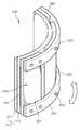
도 5는 도 4의 디스플레이 장치가 접혀진 이후의 상태를 도시한 사시도,5 is a perspective view illustrating a state after the display device of FIG. 4 is folded;
도 6은 본 발명의 제 2 실시예에 따른 디스플레이 장치가 접혀진 이후의 상태를 도시한 사시도.6 is a perspective view showing a state after the display device is folded according to the second embodiment of the present invention;
<도면의 주요 부분에 대한 부호의 간단한 설명><Brief description of symbols for the main parts of the drawings>
200...디스플레이 장치210...패널 조립체200
260...베이스 부재261...제 1 베이스 부재260
262...제 2 베이스 부재263...제 3 베이스 부재262 ...
401...이음 부재402...제 1 이음 부재401 ...
403...제 2 이음 부재404...결합 부재403 ... Second
405...접착층405 ... Adhesive layer
본 발명은 디스플레이 장치에 관한 것으로서, 보다 상세하게는 유연성을 가지는 패널 조립체와 결합되는 베이스 부재가 이와 함께 접혀지도록 구조가 개선된 유연성을 가지는 디스플레이 장치에 관한 것이다.The present invention relates to a display apparatus, and more particularly, to a display apparatus having an improved structure so that a base member coupled with a flexible panel assembly is folded therewith.
통상적으로, 플라즈마 표시장치(plasma display panel)는 복수개의 방전 전극이 형성된 두 기판상에 방전 가스를 주입하여 봉입한 다음에 방전 전압을 가하고, 이 방전 전압으로 인하여 두 전극 사이에 기체가 발광하게 되면 적절한 펄스 전압을 가하여 두 전극이 교차하는 점에 어드레싱하여 소망하는 숫자, 문자 또는 그래픽을 구현하는 디스플레이 장치를 말한다.In general, a plasma display panel injects and encapsulates a discharge gas on two substrates on which a plurality of discharge electrodes are formed, and then applies a discharge voltage, and when a gas emits light between the two electrodes due to the discharge voltage. It refers to a display device that implements a desired number, letter or graphic by applying an appropriate pulse voltage to the point where two electrodes intersect.
이러한 플라즈마 표시 장치는 방전 셀에 인가하는 구동 전압의 형식, 예컨대 방전 형식에 따라 직류형과 교류형으로 분류하고, 전극들의 구성 형태에 따라 대향 방전형 및 면 방전형으로 구분할 수 있다.Such a plasma display device may be classified into a direct current type and an alternating current type according to a type of a driving voltage applied to a discharge cell, for example, a discharge type, and may be classified into a counter discharge type and a surface discharge type according to a configuration of electrodes.
직류형 플라즈마 표시 장치는 모든 전극들이 방전 공간에 노출되는 구조로서, 대응 전극들 사이에 전하의 이동이 직접적으로 이루어진다. 반면에, 교류형 플라즈마 표시 장치는 적어도 한 전극이 유전체층에 매립되고, 대응하는 전극들 사이에 직접적인 전하의 이동이 이루어지지 않는 대신에 유전체층 표면에 방전에 의하여 생성된 이온과 전자가 부착하여 벽 전압(wall voltage)을 형성하고, 유지 전압(sustaining voltage)에 의하여 방전 유지가 가능하다.The direct current plasma display device has a structure in which all electrodes are exposed to the discharge space, and charge is directly transferred between the corresponding electrodes. On the other hand, in the AC plasma display device, at least one electrode is embedded in the dielectric layer, and instead of direct charge transfer between the corresponding electrodes, ions and electrons generated by the discharge adhere to the surface of the dielectric layer, thereby causing a wall voltage. (wall voltage) is formed, and the discharge can be maintained by the sustaining voltage.
한편, 대향 방전형 플라즈마 표시 장치는 단위 화소마다 어드레스 전극과 주사 전극이 대향하여 마련되고, 두 전극간에 어드레싱 방전 및 유지 방전이 일어나는 방식이다. 대신에 면 방전형 플라즈마 표시 장치는 각 단위 화소마다 어드레스 전극과 그에 해당되는 공통 전극과 주사 전극이 마련되어 어드레싱 전극과 유지 방전이 발생하게 되는 방식이다.On the other hand, in the opposite discharge type plasma display device, an address electrode and a scan electrode are provided to face each unit pixel, and addressing discharge and sustain discharge are generated between the two electrodes. Instead, the surface discharge plasma display device is provided with an address electrode, a common electrode, and a scan electrode corresponding to each unit pixel to generate an addressing electrode and a sustain discharge.
도 1은 종래의 디스플레이 장치(100)를 도시한 것이다.1 illustrates a
도면을 참조하면, 상기 디스플레이 장치는 전면 기판(101)과, 이와 결합되는 배면 기판(102)을 구비하는 패널 조립체(103)와, 상기 패널 조립체(103)의 후방에 결합되는 베이스 부재(104)를 포함한다.Referring to the drawings, the display apparatus includes a
상기 전면 기판(101)의 내면에는 X 전극(105)과, Y 전극(106)이 배치되고, 상기 X 전극(105)과, Y 전극(106)은 전면 유전체층(107)에 의하여 매립되어 있고, 상기 전면 유전체층(107)의 표면에는 보호막층(108)이 형성되어 있다.An
상기 배면 기판(102)의 내면에는 상기 X 및 Y 전극(105)(106)과 교차하는 방향으로 어드레스 전극(109)이 배치되고, 상기 어드레스 전극(109)은 배면 유전체층(110)에 의하여 매립되어 있다.An
또한, 상기 전면 기판(101)과, 배면 기판(102) 사이에는 격벽(111)이 배치되고, 상기 격벽(111)의 내측에는 형광체층(112)이 형성되어 있다.In addition, a
한편, 상기 배면 기판(102)의 배면에는 접착 부재(113)를 개재하는 것에 의하여 베이스 부재(104)가 설치되어 있다.On the other hand, the
이때, 상기 전면 기판(101)과, 배면 기판(104)은 후막형의 유리 기판으로 이 루어지고, 상기 베이스 부재(104)는 상기 패널 조립체(103)를 지지하기 위하여 강성을 가지는 소재, 이를테면 알루미늄과 같은 소재로 이루어져 있다.In this case, the
이러한 베이스 부재(104는 이외에도 외력에 의한 패널 조립체(103)의 충격을 흡수하고, 그 외면에 회로 소자를 포함한 구동 회로부를 부착하고, 패널 조립체(103)와 구동 회로부간의 전기적 신호 전달시 발생되는 전자기파를 접지하고, 패널 조립체(103)로부터 발생하는 열을 방출시키는 경로를 제공하는등 다양한 용도가 있다.In addition to the
최근에는, 디스플레이 장치는 패널 조립체가 접혀지거나, 일방향으로 말아서 휴대할 수 있도록 연구개발중이다. 이에 따라, 패널 조립체와 결합되는 베이스 부재도 패널 조립체와 마찬가지로 접혀지거나, 일방향으로 말아서 사용할 수 있는 구조가 요구된다.Recently, display devices are being researched and developed such that the panel assembly can be folded or rolled in one direction. Accordingly, there is a need for a structure in which the base member coupled to the panel assembly can be folded or rolled in one direction as in the panel assembly.
본 발명은 상기와 같은 문제점을 해결하기 위한 것으로서, 패널 조립체와 결합되는 베이스 부재에 별도의 이음 수단을 설치하여서 패널 조립체와 동시에 휘어질 수 있는 유연성을 가지는 디스플레이 장치을 제공하는데 그 목적이 있다.SUMMARY OF THE INVENTION The present invention has been made in view of the above-described problems, and an object of the present invention is to provide a display device having flexibility that can be bent at the same time as the panel assembly by installing a separate joint means in a base member coupled to the panel assembly.
상기와 같은 목적을 달성하기 위하여 본 발명의 일 측면에 따른 유연성을 가지는 디스플레이 장치는,In order to achieve the above object, a display device having flexibility according to an aspect of the present invention,
화상을 구현하는 유연성을 가지는 패널 조립체;A panel assembly having flexibility to implement an image;
상기 패널 조립체의 일면에 부착되며, 이를 지지하는 복수의 베이스 부재들; 및A plurality of base members attached to one surface of the panel assembly and supporting the panel assembly; And
상기 베이스 부재를 서로 연결하며, 상기 베이스 부재가 패널 조립체가 휘어지는 방향으로 휘어질 수 있도록 설치된 이음 부재들;을 포함한다.And connecting members connecting the base members to each other, wherein the base members are installed to bend in a direction in which the panel assembly is bent.
또한, 상기 베이스 부재들은 상기 패널 조립체의 일 방향을 따라서 연속적으로 배치된 판상 부재인 것을 특징으로 한다.In addition, the base members are characterized in that the plate-like member disposed continuously along one direction of the panel assembly.
게다가, 상기 이음 부재들은 상기 베이스 부재들의 외면 일측에 설치되며, 각 베이스 부재들을 하나의 몸체로 연결시키도록 결합 부재에 의하여 각 베이스 부재들과 결합된 것을 특징으로 한다.In addition, the joint members are installed on one side of the outer surface of the base members, and are coupled to each base member by a coupling member to connect each base member to a body.
여기서, 상기 이음 부재는 일방향으로 배치된 각 베이스 부재의 외면을 연속적으로 감싸는 유연성을 가진 소재인 것을 특징으로 한다.Here, the joint member is characterized in that the material having the flexibility to continuously wrap the outer surface of each base member disposed in one direction.
더욱이, 상기 베이스 부재들에는 상기 패널 조립체와 대향되는 면에 접착층이 더 형성된 것을 특징으로 한다.In addition, the base member is characterized in that the adhesive layer is further formed on the surface facing the panel assembly.
또한, 상기 이음 부재들은 상기 베이스 부재 사이에 설치되어서, 각 베이스 부재들을 하나의 몸체로 연결시키도록 결합된 것을 특징으로 한다.In addition, the joint members are installed between the base members, and are coupled to connect each base member to one body.
나아가, 상기 이음 부재는 각 베이스 부재의 양 단 사이에 개재되어서 인접한 각 베이스 부재를 동시에 연결하도록 설치된 것을 특징으로 한다.Furthermore, the joint member is interposed between both ends of each base member, characterized in that it is installed to connect each adjacent base member at the same time.
여기서, 상기 이음 부재는 인접하게 배치된 각 베이스 부재가 패널 조립체가 휘어지는 방향으로 각 베이스 부재가 휘어질 수 있도록 유연성을 가지는 소재로 이루어진 것을 특징으로 한다.Here, the joint member is characterized in that each base member disposed adjacent to each other is made of a material having flexibility to bend each base member in the direction in which the panel assembly is bent.
이하에서 첨부된 도면을 참조하면서 본 발명의 플라즈마 표시 장치의 바람 직한 실시예를 상세하게 설명하고자 한다. Hereinafter, preferred embodiments of the plasma display device of the present invention will be described in detail with reference to the accompanying drawings.
도 2는 본 발명의 제 1 실시예에 따른 디스플레이 장치(200)를 도시한 것이고, 도 3은 도 2의 Ⅰ-Ⅰ선을 따라 절개하여 결합한 것을 도시한 것이다.FIG. 2 illustrates a
도 2 및 도 3를 참조하면, 상기 디스플레이 장치(200)에는 패널 조립체(210)와, 상기 패널 조립체(210)와 결합되는 베이스 부재(260)를 포함하고 있다.2 and 3, the
상기 패널 조립체(210)에는 전면 기판(211)이 마련되어 있다. 상기 전면 기판(211)은 광투과성이 우수한 소재인 투명판으로 이루어져 있다. 대안으로는, 상기 전면 기판(211)은 반사 휘도를 감소시켜서 명실 콘트라스트를 향상시키기 위하여 착색하거나, 반투명판을 사용할 수도 있다.The
상기 전면 기판(211)의 하방에는 방전 셀(S)을 구획하고, 인접하는 방전 셀(S) 사이의 전기적, 광학적 크로스 토크를 방지하기 위하여 격벽(212)이 배치되어 있다. 상기 격벽(212) 내에는 복수의 방전 전극쌍(213)(214)이 매립되어 있다.A
상기 격벽(212)은 인접한 제 1 방전 전극(213)과, 제 2 방전 전극(214)들간에 직접 통전되는 것을 방지함과 동시에, 양이온 또는 전자가 제 1 및 제 2 방전 전극(213)(214)을 손상시키는 것을 방지하고, 전하를 유도하여 벽전하를 축적할 수 고유전성의 유전체로 형성되는 것이 바람직하다.The
상기 격벽(212)은 원형의 횡단면을 가지는 방전 셀(S)을 형성하도록 형성되어 있으나, 반드시 이에 한정되는 것은 아니다. 즉, 상기 격벽(212)은 복수의 방전 셀(S)을 구획할 수 있는 구조라면 다양한 패턴, 예컨대, 삼각형, 사각형, 오각형등의 다각형이나, 원형이나, 비원형의 횡단면의 방전 셀(S)을 가지도록 형성될 수도 있으며, 델타형(delta type)이나, 와플형(waffle type)이나, 미앤더형(meander type)의 방전 셀(S)을 한정하도록 형성시킬 수도 있을 것이다.The
상기 제 1 방전 전극(213)과, 제 2 방전 전극(214)은 하나의 방전 셀(S)마다 각각 1개씩 상기 패널(200)이 배치된 방향과 수직 방향으로 소정 간격 이격되게 배치되어 있다. 상기 제 1 방전 전극(213)은 상기 전면 기판(211)과 상대적으로 인접하게 배치되어 있으며, 제 2 방전 전극(214)은 배면 기판(215)과 상대적으로 인접하게 배치되어 있다.The
상기 제 1 방전 전극(213)은 패널(200)의 Y 방향을 따라서 배치된 방전 셀(S)의 둘레를 감싸면서 연장되어 있다. 이러한 제 1 방전 전극(213)은 방전 셀(S)의 둘레를 개루프(open loop)나, 폐루프(closed loop) 형식으로 감싸고 있다. 상기 제 1 방전 전극(213)은 방전 셀(S)의 횡단면과 실질적으로 동일한 형상을 가지는 것이 바람직하다고 할 것이다.The
상기 제 2 방전 전극(214)은 상기 제 1 방전 전극(213)과 교차하는 방향인 패널(200)의 X 방향을 따라서 배치된 방전 셀(S)의 둘레를 감싸면서 연장되어 있다. 이러한 제 2 방전 전극(214)은 상기 격벽(212) 내에서 상기 전면 기판(211)에 대하여 수직 방향인 패널(200)의 Z 방향으로 상기 제 1 방전 전극(213)과 이격되어 배치되어 있다. 상기 제 2 방전 전극(214)은 방전 셀(S)의 횡단면과 실질적으로 동일한 형상이다.The
상기 제 1 방전 전극(213)과, 제 2 방전 전극(214)은 전면 기판(211)의 내표면과 같은 직접적으로 가시광 투과율을 감소시키는 위치에 배치되어 있지 않기 때 문에, 알루미늄, 구리 등과 같은 도전성이 우수한 금속재로 형성시킬 수가 있다.Since the
한편, 상기 플라즈마 디스플레이 패널(200)은 제 1 및 제 2 방전 전극(213)(214)으로 이루어진 2 전극 구조로서, 제 1 방전 전극(213)과, 제 2 방전 전극(214)중 어느 하나는 주사 및 유지 전극의 역할을 하고, 다른 하나는 어드레스 및 유지 전극의 작용을 하고 있다.Meanwhile, the
대안으로는, 플라즈마 디스플레이 패널이 3전극 구조를 가질 경우에는 유지 방전을 일으키는 제 1 및 제 2 방전 전극(213)(214) 이외에 제 2 방전 전극(214)과 교차하는 방향으로 배치되어서 어드레싱 방전을 일으키는 제 3 방전 전극이 더 형성될 수가 있을 것이다.Alternatively, when the plasma display panel has a three-electrode structure, in addition to the first and
상기 격벽(212)의 하방에는 배면 기판(215)이 배치되어 있다. 상기 배면 기판(215)은 상기 전면 기판(211)과, 그 사이에 배치된 격벽(212)과 함께 결합되어서, 방전 셀(S) 내에 주입된 방전 가스를 밀봉시키고 있다. 상기 배면 기판(214)의 윗면은 상기 격벽(212)의 아랫면과 밀착되도록 형성되어 있다.The
한편, 상기 격벽(212)의 표면에는 보호막층(216)이 형성될 수가 있다. 상기 보호막층(216)은 플라즈마 입자의 스퍼터링에 의하여 격벽(212)과, 제 1 및 제 2 방전 전극(213)(214)이 손상되는 것을 방지하고, 이와 동시에 이차 전자를 방출하여서 방전 전압을 낮추어 주는 역할을 하고 있다. 상기 보호막층(216)으로는 마그네슘 옥사이드(MgO)를 사용할 수가 있다.Meanwhile, a
또한, 각각의 방전 셀(S)과 대응되는 전면 기판(211)의 내면에는 소정의 깊이를 가지도록 그루브(211a)가 형성되어 있다. 상기 그루브(211a)는 각 방전 셀(S) 마다 단속적으로 형성되어 있다. 상기 그루브(211a)는 실질적으로 방전 셀(S)과 동일한 형상이다.In addition, a
이러한 그루브(211a)에는 적,녹,청색의 형광체층(217)이 형성되어 있다. 대안으로는, 상기 형광체층(217)은 그 위치를 달리하여 다른 영역에 형성시킬 수도 있을 것이다. 이를테면, 상기 격벽(212)의 내측벽이나, 배면 기판(215)의 내표면상에 형성시킬 수가 있다.Red, green, and blue phosphor layers 217 are formed in the
상기 형광체층(217)은 자외선을 받아서 가시광을 발생하는 성분을 포함하고 있는데, 적색 발광셀에 형성된 형광체층은 Y(V,P)O4:Eu 등과 같은 형광체를 포함하며, 녹색 발광 방전셀에 형성된 형광체층은 Zn2SiO4:Mn, YBO3:Tb 등과 같은 형광체를 포함하며, 청색 발광 방전셀에 형성된 형광체층은 BAM:Eu 등과 같은 형광체를 포함한다.The
또한, 방전 셀(S) 내에는 네온(Ne), 크세논(Xe)등 및 이들의 혼합 기체와 같은 방전 가스가 봉입되어 있다. 본 실시예에 경우, 방전면이 증가하고, 방전 영역이 확대될 수 있어서, 플라즈마의 양이 증가하므로, 저전압 구동이 가능하게 된다. 따라서, 고농도 Xe 가스를 방전 가스로 사용한다 할지라도, 저전압 구동이 가능하게 됨으로써, 발광 효율을 획기적으로 향상시킬 수가 있다.In the discharge cell S, a discharge gas such as neon (Ne), xenon (Xe), or a mixed gas thereof is enclosed. In the present embodiment, the discharge surface is increased and the discharge region can be enlarged, so that the amount of plasma is increased, thereby enabling low voltage driving. Therefore, even if a high concentration of Xe gas is used as the discharge gas, the low voltage driving becomes possible, which can significantly improve the luminous efficiency.
이때, 상기 전면 기판(211)과, 배면 기판(215)은 유연성을 가진 기판, 예컨대, 투명한 필름이나, 착색된 필름이나, 반투명한 필름등을 이용하여 제조될 수 있다. 또한, X 전극(213)과 Y 전극(214)을 매립한 격벽(212)도 유연성을 가진 필름을 다수장 적층하여 제조되어 있다. 이에 따라, 상기 패널 조립체(210)는 일방향으로 휘어지거나, 접을 수 있는 유연성을 가지게 된다.In this case, the
여기서, 상기 패널 조립체(210)의 후방에는 이와 함께 동일한 방향으로 접혀지거나, 일방향으로 말아질 수 있는 베이스 부재(260)가 결합되어 있다.Here, the
보다 상세하게는 다음에 설명하는 바와 같다.In more detail, it is as following.
도 4는 도 2의 디스플레이 장치(200)가 휘어지기 이전의 상태를 도시한 것이고, 도 5는 도 4의 디스플레이 장치(200)가 휘어진 이후의 상태를 도시한 것이다.4 illustrates a state before the
도 4를 참조하면, 상기 패널 조립체(210)의 후방에는 복수의 베이스 부재들(260)이 배치되어 있다. 상기 베이스 부재들(260)은 상기 패널 조립체(210)의 길이 방향을 따라서 연속적으로 배치된 제 1 베이스 부재(261)와, 제 2 베이스 부재(262)와, 제 3 베이스 부재(263), ... , 제 n 베이스 부재를 포함하고 있다.Referring to FIG. 4, a plurality of
상기 제 1 내지 제 2 베이스 부재는 각각 판상 부재로 이루어지며, 상기 패널 조립체(210)를 지지하고, 이로부터 발생되는 열을 외부로 방출하기 위하여 알루미늄판과 같은 열전도성이 우수한 소재로 이루어지는 것이 바람직하다.Each of the first to second base members may be formed of a plate member, and may be formed of a material having excellent thermal conductivity such as an aluminum plate to support the
또한, 제 1 베이스 부재(261)와, 제 2 베이스 부재(262)와, 제 3 베이스 부재(263) , ... , 제 n 베이스 부재가 상기 패널 조립체(210)의 길이 방향으로 배치될 때에, 상기 베이스 부재들(260)은 상기 패널 조립체(210)의 전 영역을 커버하도록 설치되어 있다.In addition, when the
이때, 상기 제 1 베이스 부재(261)와, 제 2 베이스 부재(262) 사이와, 제 2 베이스 부재(262)와, 제 3 베이스 부재(263) 사이와 같은 단위 베이스 부재 사이는 상기 베이스 부재들(260)이 일방향으로 접혀질 때 서로 간섭되는 것을 방지하기 위하여 공간부(409)가 형성되어 있다.In this case, the base members may be disposed between the
이러한 제 1 베이스 부재(261)와, 제 2 베이스 부재(262)와, 제 3 베이스 부재(263) , ... , 제 n 베이스 부재는 이음 부재(401)에 의하여 서로 연결되어 있다. 상기 이음 부재(401)는 상기 제 1 베이스 부재(261)와, 제 2 베이스 부재(262)와, 제 3 베이스 부재(263) , ... , 제 n 베이스 부재를 서로 연결하여, 상기 베이스 부재들(260)이 패널 조립체(210)가 휘어지는 방향으로 휘어질 수 있도록 고분자 수지와 같은 유연성을 가진 소재로 이루어져 있다.The
상기 이음 부재(401)는 상기 제 1 베이스 부재(261)와, 제 2 베이스 부재(262)와, 제 3 베이스 부재(263) , ... , 제 n 베이스 부재의 상부에 설치된 제 1 이음 부재(402)와, 하부에 설치된 제 2 이음 부재(403)를 포함하고 있다. 이러한 이음 부재(401)는 상기 제 1 베이스 부재(261)와, 제 2 베이스 부재(262)와, 제 3 베이스 부재(263) , ... , 제 n 베이스 부재의 외면에 동시에 접촉하여서 하나의 몸체로 연결시킬 수 있도록 스트립형을 이루고 있다.The
또한, 상기 제 1 이음 부재(402)와, 제 2 이음 부재(403)는 결합 부재(404)에 의하여 제 1 베이스 부재(261)와, 제 2 베이스 부재(262)와, 제 3 베이스 부재(263) , ... , 제 n 베이스와 결합되어 있다. 상기 결합 부재(404)를 이용한 결합 방식은 리벳팅이나, 나사 결합이나, 톡싱이나, 레이저 가공법등 다양한 체결 방식이 있다.In addition, the first
이처럼, 상기 제 1 이음 부재(402)와, 제 2 이음 부재(403)는 일방향으로 배 치된 제 1 베이스 부재(261)와, 제 2 베이스 부재(262)와, 제 3 베이스 부재(263) , ... , 제 n 베이스 부재의 외면을 연속적으로 감싸고 있다.As such, the first
한편, 제 1 베이스 부재(261)와, 제 2 베이스 부재(262)와, 제 3 베이스 부재(263) , ... , 제 n 베이스 부재에는 상기 패널 조립체(210)와 대향되는 면상에 접착층(405)이 형성되어 있다. 상기 접착층(405)은 상기 배면 기판(215)과, 각 베이스 부재들(260)의 전면 사이에 개재되어서, 이들을 결합시키고 있다. 상기 접착층(405)으로는 양면 테이프나, 방열 쉬트나, 이들을 혼합시켜서 이용할 수가 있다.Meanwhile, the
상기와 같은 구조의 디스플레이 장치(200)는 도 5에 도시된 바와 같이, 상기 패널 조립체(210)의 배면에 접착층(405)을 개재하여서 제 1 베이스 부재(261)와, 제 2 베이스 부재(262)와, 제 3 베이스 부재(263) , ... , 제 n 베이스 부재가 부착되며, 상기 제 1 베이스 부재(261)와, 제 2 베이스 부재(262)와, 제 3 베이스 부재(263) , ... , 제 n 베이스 부재의 상하단부 외면에는 제 1 이음 부재(402)(403)가 결합 부재(404)에 의하여 결합되어 있으므로, 화살표로 표시한 바와 같이, 상기 디스플레이 장치(200)는 일방향으로 휘거나 접혀질 수가 있다.As shown in FIG. 5, the
도 6은 본 발명의 제 2 실시예에 따른 디스플레이 장치(600)를 도시한 것이다.6 illustrates a
여기서, 앞선 도면에서와 동일한 부재는 동일한 기능을 하는 동일한 부재를 가리킨다.Here, the same members as in the previous drawings refer to the same members having the same function.
도면을 참조하면, 상기 디스플레이 장치(600)는 패널 조립체(210)와, 상기 패널 조립체(210)의 후방에 결합되는 베이스 부재들(600)을 포함하고 있다.Referring to the drawings, the
상기 패널 조립체(210)는 전면 기판(211)가, 상기 전면 기판(211)과 결합되는 배면 기판(215)을 포함하며, 상기 전면 및 배면 기판(211)(215)은 유연성을 가지는 기판으로 제조되어서 일방향으로 휘어질 수가 있다.The
상기 배면 기판(215)의 배면에는 베이스 부재들(600)이 설치되어 있다. 상기 베이스 부재들(600)은 제 1 베이스 부재(661)와, 제 2 베이스 부재(662)와, 제 3 베이스 부재(663) , ... , 제 n 베이스 부재를 포함하고 있다. 상기 제 1 베이스 부재(661)와, 제 2 베이스 부재(662)와, 제 3 베이스 부재(663) , ... , 제 n 베이스 부재는 상기 패널 조립체(210)의 길이 방향을 따라서 연속적으로 배치되어서, 상기 패널 조립체(210)의 크기와 상응하는 크기를 가지고 있다. 또한, 상기 베이스 부재들(600)은 상기 패널 조립체(210)를 지지하고, 이로부터 발생되는 열을 흡수하여 외부로 방출하기 위하여 열 방열성이 우수한 판상 부재로 이루어져 있다.
이때, 제 1 베이스 부재(661)와, 제 2 베이스 부재(662)의 사이에 해당되는 영역과, 상기 제 2 베이스 부재(662)와, 제 3 베이스 부재(663)의 사이에 해당되는 영역과 같은 각 단위 베이스 부재 사이의 영역에 이음 부재(601)가 설치되어서, 각 베이스 부재들(660)를 하나의 몸체로 연결시키기 위하여 결합되어 있다.In this case, an area corresponding to the
이를 위하여, 상기 이음 부재(601)는 제 1 베이스 부재(661)와, 제 2 베이스 부재(662)의 사이에 해당되는 영역에 개재되는 제 1 이음 부재(602)와, 제 2 베이스 부재(662)와, 제 3 베이스 부재(663) 사이에 해당되는 영역에 개재되는 제 2 이음 부재(603)등와 같이 n 개의 이음 부재를 포함하고 있다. 상기 이음 부재(601)는 인접하게 배치된 각 베이스 부재들(660)가 패널 조립체(210)가 휘어지는 방향으로 휘어질 수 있도록 유연성을 가지는 소재를 이루어져 있다.To this end, the
이러한 이음 부재(601)는 상기 각 베이스 부재들(660)의 양 단 사이에 개재시, 상기 베이스 부재들(660)과 대략 동일한 높이를 가지고 설치되며, 상기 각 베이스 부재들(660)의 양 단을 양 측에서 동시에 삽입끼워맞춤할 수 있도록 인서트 홈(601a)이 형성되어 있다. 상기 인서트 홈(601a)은 상기 이음 부재(601)의 높이 방향을 따라서 전체적으로 소정 깊이 형성되어 있다.The
상기 인서트 홈(601a)에는 이웃하는 제 1 베이스 부재(661)와, 제 2 베이스 부재(662)와, 제 3 베이스 부재(663) , ... , 제 n 베이스 부재의 단부가 삽입되어있다. 이에 따라, 상기 제 1 베이스 부재(661)와, 제 2 베이스 부재(662)와, 제 3 베이스 부재(663) , ... , 제 n 베이스 부재는 그 사이에 개재되는 이음 부재(601)에 의하여 연속적으로 동시에 연결되어 있다.The end portions of the neighboring
또한, 상기 각 제 1 베이스 부재(661)와, 제 2 베이스 부재(662)와, 제 3 베이스 부재(663) , ... , 제 n 베이스 부재는 상기 이음 부재(601)의 결합에 의하여 동일한 방향으로 동시에 휘어지거나, 인접하는 베이스 부재들(660)별로 접혀지는 방향을 달리하여 접혀질 수도 있다.In addition, each of the
이러한 이음 부재(601)는 인서트 홈(601a)을 통하여 결합되는 제 1 베이스 부재(661)와, 제 2 베이스 부재(662)와, 제 3 베이스 부재(663) , ... , 제 n 베이스 부재와의 결합을 위하여 결합 부재(604)에 의하여 결합가능하다. 상기 결합 부재(604)를 이용한 결합 방식은 리벳팅이나, 보울트 결합이나, 나사 결합이나, 톡싱이나, 레이저 결합법등 어느 하나에 한정되는 것은 아니다. ,The
이상의 설명에서와 같이 본 발명의 유연성을 가지는 디스플레이 장치는 유연성을 가지는 패널 조립체의 후방에서 이를 지지하는 베이스 부재가 이음 부재에 의하여 이와 동일한 방향으로 휘어지거나, 접혀질 수 있다.As described above, the flexible display device of the present invention may be bent or folded in the same direction by the joint member to support the base member at the rear of the flexible panel assembly.
본 발명은 도면에 도시된 일 실시예를 참고로 설명되었으나 이는 예시적인 것에 불과하며, 본 기술 분야의 통상의 지식을 가진 자라면 이로부터 다양한 변형 및 균등한 타 실시예가 가능하다는 점을 이해할 것이다. 따라서, 본 발명의 진정한 기술적 보호 범위는 첨부된 등록청구범위의 기술적 사상에 의해 정해져야 할 것이다.Although the present invention has been described with reference to one embodiment shown in the drawings, this is merely exemplary, and those skilled in the art will understand that various modifications and equivalent other embodiments are possible therefrom. Therefore, the true technical protection scope of the present invention will be defined by the technical spirit of the appended claims.
Claims (12)
Translated fromKoreanPriority Applications (2)
| Application Number | Priority Date | Filing Date | Title |
|---|---|---|---|
| KR1020060023510AKR100768208B1 (en) | 2006-03-14 | 2006-03-14 | Flexible display device |
| US11/716,919US7791279B2 (en) | 2006-03-14 | 2007-03-12 | Flexible plasma display panel assembly incorporting base members coupled with connection members for supporting the flexible panel assembly |
Applications Claiming Priority (1)
| Application Number | Priority Date | Filing Date | Title |
|---|---|---|---|
| KR1020060023510AKR100768208B1 (en) | 2006-03-14 | 2006-03-14 | Flexible display device |
Publications (2)
| Publication Number | Publication Date |
|---|---|
| KR20070093545A KR20070093545A (en) | 2007-09-19 |
| KR100768208B1true KR100768208B1 (en) | 2007-10-17 |
Family
ID=38557826
Family Applications (1)
| Application Number | Title | Priority Date | Filing Date |
|---|---|---|---|
| KR1020060023510AExpired - Fee RelatedKR100768208B1 (en) | 2006-03-14 | 2006-03-14 | Flexible display device |
Country Status (2)
| Country | Link |
|---|---|
| US (1) | US7791279B2 (en) |
| KR (1) | KR100768208B1 (en) |
Cited By (2)
| Publication number | Priority date | Publication date | Assignee | Title |
|---|---|---|---|---|
| KR20140095316A (en)* | 2013-01-24 | 2014-08-01 | 엘지전자 주식회사 | Rear cover and display apparatus including the same |
| KR20160035133A (en)* | 2014-09-22 | 2016-03-31 | 삼성디스플레이 주식회사 | Display device |
Families Citing this family (32)
| Publication number | Priority date | Publication date | Assignee | Title |
|---|---|---|---|---|
| KR100838070B1 (en)* | 2006-11-07 | 2008-06-16 | 삼성에스디아이 주식회사 | Plasma display panel |
| JP5108293B2 (en)* | 2006-12-20 | 2012-12-26 | 富士フイルム株式会社 | Portable device and imaging device |
| KR100863914B1 (en)* | 2007-09-06 | 2008-10-17 | 삼성에스디아이 주식회사 | Plasma display device |
| KR20120068772A (en) | 2009-09-16 | 2012-06-27 | 가부시키가이샤 한도오따이 에네루기 켄큐쇼 | Light-emitting device and manufacturing method thereof |
| KR101211371B1 (en)* | 2010-09-16 | 2012-12-13 | 주식회사 토비스 | Method for manufacturing display panel with curved shape |
| US9117384B2 (en) | 2011-03-18 | 2015-08-25 | Blackberry Limited | System and method for bendable display |
| US9812074B2 (en) | 2011-03-18 | 2017-11-07 | Blackberry Limited | System and method for foldable display |
| US9711752B2 (en)* | 2011-12-19 | 2017-07-18 | Lg Electronics Inc. | Display apparatus |
| KR102090642B1 (en)* | 2013-04-25 | 2020-03-18 | 엘지전자 주식회사 | Display apparatus and rear cover used for the same |
| TWI688850B (en)* | 2013-08-13 | 2020-03-21 | 飛利斯有限公司 | Article with electronic display |
| WO2015031426A1 (en) | 2013-08-27 | 2015-03-05 | Polyera Corporation | Flexible display and detection of flex state |
| CN105793781B (en) | 2013-08-27 | 2019-11-05 | 飞利斯有限公司 | Attachable device with deflection electronic component |
| WO2015038684A1 (en) | 2013-09-10 | 2015-03-19 | Polyera Corporation | Attachable article with signaling, split display and messaging features |
| WO2015100224A1 (en) | 2013-12-24 | 2015-07-02 | Polyera Corporation | Flexible electronic display with user interface based on sensed movements |
| TWI676880B (en) | 2013-12-24 | 2019-11-11 | 美商飛利斯有限公司 | Dynamically flexible article |
| JP6639400B2 (en) | 2013-12-24 | 2020-02-05 | フレックステラ, インコーポレイテッドFlexterra, Inc. | Support structure for attachable two-dimensional flexible electronic device |
| CN106030688B (en) | 2013-12-24 | 2020-01-24 | 飞利斯有限公司 | flexible electronics |
| US20150227245A1 (en) | 2014-02-10 | 2015-08-13 | Polyera Corporation | Attachable Device with Flexible Electronic Display Orientation Detection |
| KR102243856B1 (en) | 2014-04-07 | 2021-04-26 | 삼성디스플레이 주식회사 | Display apparatus |
| WO2015184045A2 (en) | 2014-05-28 | 2015-12-03 | Polyera Corporation | Device with flexible electronic components on multiple surfaces |
| CN104050882B (en)* | 2014-05-30 | 2016-07-20 | 京东方科技集团股份有限公司 | A kind of display device |
| KR20160035132A (en) | 2014-09-22 | 2016-03-31 | 삼성디스플레이 주식회사 | Display device |
| EP3242282A4 (en)* | 2014-12-31 | 2018-07-25 | Shenzhen Royole Technologies Co., Ltd. | Flexible display device and electronic device |
| WO2016138356A1 (en) | 2015-02-26 | 2016-09-01 | Polyera Corporation | Attachable device having a flexible electronic component |
| USD825559S1 (en)* | 2015-06-05 | 2018-08-14 | Gtek Group Limited | Curvature adjustable display |
| KR102343720B1 (en) | 2015-06-11 | 2021-12-28 | 삼성디스플레이 주식회사 | Display device |
| USD747718S1 (en)* | 2015-10-14 | 2016-01-19 | Nanolumens Acquisition, Inc. | Ellipsoidal shaped display |
| KR102369318B1 (en)* | 2017-08-30 | 2022-03-02 | 엘지디스플레이 주식회사 | Flexible display device |
| KR102438259B1 (en)* | 2017-12-04 | 2022-08-30 | 엘지디스플레이 주식회사 | Display Unit |
| KR102408844B1 (en)* | 2017-12-06 | 2022-06-13 | 엘지디스플레이 주식회사 | Flexible display device |
| KR102418576B1 (en) | 2017-12-11 | 2022-07-08 | 엘지디스플레이 주식회사 | Back Cover and Display Device having the same |
| KR102661698B1 (en)* | 2018-11-29 | 2024-05-02 | 삼성디스플레이 주식회사 | Flexible display apparatus |
Citations (4)
| Publication number | Priority date | Publication date | Assignee | Title |
|---|---|---|---|---|
| US5469020A (en) | 1994-03-14 | 1995-11-21 | Massachusetts Institute Of Technology | Flexible large screen display having multiple light emitting elements sandwiched between crossed electrodes |
| JP2000199891A (en)* | 1999-01-06 | 2000-07-18 | Rohm Co Ltd | Flexible liquid crystal display panel, liquid crystal display device and manufacture of liquid crystal display panel |
| JP2003280548A (en)* | 2002-03-25 | 2003-10-02 | Toshiba Corp | Flexible display panel |
| WO2005017868A1 (en)* | 2003-08-19 | 2005-02-24 | Koninklijke Philips Electronics N.V. | Display device with flexible substrate and shift register |
Family Cites Families (3)
| Publication number | Priority date | Publication date | Assignee | Title |
|---|---|---|---|---|
| JP2003036034A (en)* | 2001-07-25 | 2003-02-07 | Sony Corp | Method for producing display device and display device |
| KR100542222B1 (en)* | 2003-09-02 | 2006-01-10 | 삼성에스디아이 주식회사 | Reinforcement member of plasma display device and chassis base for plasma display device |
| KR100637217B1 (en)* | 2005-03-03 | 2006-10-23 | 삼성에스디아이 주식회사 | Plasma display device |
- 2006
- 2006-03-14KRKR1020060023510Apatent/KR100768208B1/ennot_activeExpired - Fee Related
- 2007
- 2007-03-12USUS11/716,919patent/US7791279B2/ennot_activeExpired - Fee Related
Patent Citations (4)
| Publication number | Priority date | Publication date | Assignee | Title |
|---|---|---|---|---|
| US5469020A (en) | 1994-03-14 | 1995-11-21 | Massachusetts Institute Of Technology | Flexible large screen display having multiple light emitting elements sandwiched between crossed electrodes |
| JP2000199891A (en)* | 1999-01-06 | 2000-07-18 | Rohm Co Ltd | Flexible liquid crystal display panel, liquid crystal display device and manufacture of liquid crystal display panel |
| JP2003280548A (en)* | 2002-03-25 | 2003-10-02 | Toshiba Corp | Flexible display panel |
| WO2005017868A1 (en)* | 2003-08-19 | 2005-02-24 | Koninklijke Philips Electronics N.V. | Display device with flexible substrate and shift register |
Cited By (4)
| Publication number | Priority date | Publication date | Assignee | Title |
|---|---|---|---|---|
| KR20140095316A (en)* | 2013-01-24 | 2014-08-01 | 엘지전자 주식회사 | Rear cover and display apparatus including the same |
| KR102104444B1 (en)* | 2013-01-24 | 2020-04-24 | 엘지전자 주식회사 | Rear cover and display apparatus including the same |
| KR20160035133A (en)* | 2014-09-22 | 2016-03-31 | 삼성디스플레이 주식회사 | Display device |
| KR102241557B1 (en)* | 2014-09-22 | 2021-04-19 | 삼성디스플레이 주식회사 | Display device |
Also Published As
| Publication number | Publication date |
|---|---|
| US20070228952A1 (en) | 2007-10-04 |
| US7791279B2 (en) | 2010-09-07 |
| KR20070093545A (en) | 2007-09-19 |
Similar Documents
| Publication | Publication Date | Title |
|---|---|---|
| KR100768208B1 (en) | Flexible display device | |
| US20060267499A1 (en) | Plasma display panel (PDP) | |
| JP2000021313A (en) | Plasma display panel | |
| KR100581952B1 (en) | Plasma display panel | |
| JP2007134323A (en) | Plasma display panel and plasma display apparatus including the same | |
| US20070046205A1 (en) | Plasma display panel and method of manufacturing the same | |
| JP4382707B2 (en) | Plasma display panel | |
| KR20060060993A (en) | Curved plasma display panel, manufacturing method thereof and curved plasma display device having same | |
| JP2007265957A (en) | Plasma display panel | |
| JP4292178B2 (en) | Plasma display panel | |
| US20070228957A1 (en) | Plasma display module and plasma display apparatus including the same | |
| US20060132038A1 (en) | Plasma display panel | |
| US20080048549A1 (en) | Plasma display panel and method of manufacturing the same | |
| US7453209B2 (en) | Plasma display panel having pairs of address electrodes between scan and sustain electrodes | |
| US7486023B2 (en) | Single layer discharge electrode configuration for a plasma display panel | |
| KR100637158B1 (en) | Plasma display panel | |
| KR100708703B1 (en) | Plasma display panel | |
| US20090021168A1 (en) | Plasma display panel | |
| JP2009070820A (en) | Plasma display panel | |
| KR100670337B1 (en) | Plasma display panel | |
| KR100637160B1 (en) | Plasma display panel | |
| KR100777730B1 (en) | Plasma display panel | |
| KR100846602B1 (en) | Plasma display panel | |
| US20070228968A1 (en) | Plasma display panel and flat panel display device including the same | |
| KR100637236B1 (en) | Plasma display panel |
Legal Events
| Date | Code | Title | Description |
|---|---|---|---|
| A201 | Request for examination | ||
| PA0109 | Patent application | St.27 status event code:A-0-1-A10-A12-nap-PA0109 | |
| PA0201 | Request for examination | St.27 status event code:A-1-2-D10-D11-exm-PA0201 | |
| E902 | Notification of reason for refusal | ||
| PE0902 | Notice of grounds for rejection | St.27 status event code:A-1-2-D10-D21-exm-PE0902 | |
| P11-X000 | Amendment of application requested | St.27 status event code:A-2-2-P10-P11-nap-X000 | |
| P13-X000 | Application amended | St.27 status event code:A-2-2-P10-P13-nap-X000 | |
| PG1501 | Laying open of application | St.27 status event code:A-1-1-Q10-Q12-nap-PG1501 | |
| E701 | Decision to grant or registration of patent right | ||
| PE0701 | Decision of registration | St.27 status event code:A-1-2-D10-D22-exm-PE0701 | |
| GRNT | Written decision to grant | ||
| PR0701 | Registration of establishment | St.27 status event code:A-2-4-F10-F11-exm-PR0701 | |
| PR1002 | Payment of registration fee | St.27 status event code:A-2-2-U10-U11-oth-PR1002 Fee payment year number:1 | |
| PG1601 | Publication of registration | St.27 status event code:A-4-4-Q10-Q13-nap-PG1601 | |
| R18-X000 | Changes to party contact information recorded | St.27 status event code:A-5-5-R10-R18-oth-X000 | |
| R18-X000 | Changes to party contact information recorded | St.27 status event code:A-5-5-R10-R18-oth-X000 | |
| PR1001 | Payment of annual fee | St.27 status event code:A-4-4-U10-U11-oth-PR1001 Fee payment year number:4 | |
| PR1001 | Payment of annual fee | St.27 status event code:A-4-4-U10-U11-oth-PR1001 Fee payment year number:5 | |
| FPAY | Annual fee payment | Payment date:20120921 Year of fee payment:6 | |
| PR1001 | Payment of annual fee | St.27 status event code:A-4-4-U10-U11-oth-PR1001 Fee payment year number:6 | |
| P22-X000 | Classification modified | St.27 status event code:A-4-4-P10-P22-nap-X000 | |
| FPAY | Annual fee payment | Payment date:20130924 Year of fee payment:7 | |
| PR1001 | Payment of annual fee | St.27 status event code:A-4-4-U10-U11-oth-PR1001 Fee payment year number:7 | |
| R18-X000 | Changes to party contact information recorded | St.27 status event code:A-5-5-R10-R18-oth-X000 | |
| LAPS | Lapse due to unpaid annual fee | ||
| PC1903 | Unpaid annual fee | St.27 status event code:A-4-4-U10-U13-oth-PC1903 Not in force date:20141012 Payment event data comment text:Termination Category : DEFAULT_OF_REGISTRATION_FEE | |
| PC1903 | Unpaid annual fee | St.27 status event code:N-4-6-H10-H13-oth-PC1903 Ip right cessation event data comment text:Termination Category : DEFAULT_OF_REGISTRATION_FEE Not in force date:20141012 | |
| P22-X000 | Classification modified | St.27 status event code:A-4-4-P10-P22-nap-X000 | |
| R18-X000 | Changes to party contact information recorded | St.27 status event code:A-5-5-R10-R18-oth-X000 | |
| P22-X000 | Classification modified | St.27 status event code:A-4-4-P10-P22-nap-X000 |