KR100766860B1 - Stereoscopic scanner - Google Patents
Stereoscopic scannerDownload PDFInfo
- Publication number
- KR100766860B1 KR100766860B1KR1020020041122AKR20020041122AKR100766860B1KR 100766860 B1KR100766860 B1KR 100766860B1KR 1020020041122 AKR1020020041122 AKR 1020020041122AKR 20020041122 AKR20020041122 AKR 20020041122AKR 100766860 B1KR100766860 B1KR 100766860B1
- Authority
- KR
- South Korea
- Prior art keywords
- scanner
- projection mirror
- dimensional object
- mounting table
- transparent mounting
- Prior art date
- Legal status (The legal status is an assumption and is not a legal conclusion. Google has not performed a legal analysis and makes no representation as to the accuracy of the status listed.)
- Expired - Lifetime
Links
Images


Classifications
- H—ELECTRICITY
- H04—ELECTRIC COMMUNICATION TECHNIQUE
- H04N—PICTORIAL COMMUNICATION, e.g. TELEVISION
- H04N1/00—Scanning, transmission or reproduction of documents or the like, e.g. facsimile transmission; Details thereof
- H04N1/00795—Reading arrangements
- H04N1/00827—Arrangements for reading an image from an unusual original, e.g. 3-dimensional objects
- G—PHYSICS
- G06—COMPUTING OR CALCULATING; COUNTING
- G06V—IMAGE OR VIDEO RECOGNITION OR UNDERSTANDING
- G06V20/00—Scenes; Scene-specific elements
- G06V20/60—Type of objects
- G06V20/64—Three-dimensional objects
Landscapes
- Engineering & Computer Science (AREA)
- Multimedia (AREA)
- Signal Processing (AREA)
- Physics & Mathematics (AREA)
- General Physics & Mathematics (AREA)
- Theoretical Computer Science (AREA)
- Length Measuring Devices By Optical Means (AREA)
- Image Input (AREA)
- Footwear And Its Accessory, Manufacturing Method And Apparatuses (AREA)
Abstract
Translated fromKoreanDescription
Translated fromKorean도 1 및 도 2는 본원인이 선출원한 종래의 스캐너를 도시한 것으로서,1 and 2 show a conventional scanner, which the applicant has filed in advance,
도 1은 외관을 나타낸 사시도.1 is a perspective view showing the appearance.
도 2는 내부 구조를 나타낸 사시도.2 is a perspective view showing an internal structure.
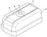
도 3은 본 발명에 따른 스캐너의 외관을 나타낸 사시도.3 is a perspective view showing the appearance of a scanner according to the present invention;
도 4는 도 3의 스캐너에서 외장을 제거하여 스캐너의 내부 구조를 나타낸 평면도.4 is a plan view showing the internal structure of the scanner by removing the exterior from the scanner of FIG.
도 5는 각 구성요소들의 배치 관계를 명확하게 나타내기 위한 스캐너의 정단면도.Fig. 5 is a front sectional view of the scanner for clearly showing the placement relationship of each component.
- 도면의 주요부분에 대한 부호의 설명 --Explanation of symbols for the main parts of the drawings-
20 : 스캐너 몸체 30,31 : 덮개판20: scanner body 30, 31: cover plate
32,33 : 통과홈 40 : 투명 재치대32,33: Passing groove 40: Transparent mounting table
50 : 투영경 61,62 : 브래킷50:
71,72 : 상부 카메라 73,74 : 하부 카메라71,72:
81,82 : 레이저 조사기 90 : 모터81,82: laser irradiator 90: motor
91 : 리드 스크류 100 : 램프91: lead screw 100: lamp
본 발명은 입체물 스캐너에 관한 것으로서, 보다 구체적으로는 신발 제조를 위해 사람의 발 형상을 스캐닝하는 스캐너에 관한 것이다.The present invention relates to a three-dimensional scanner, and more particularly to a scanner for scanning the shape of a person's foot for shoe manufacturing.
일반적으로, 스캐너는 문서나 그림 등이 재치되는 평면 유리판 하부에 CCD 카메라와 광원이 설치된 구조로 이루어져 있다. 이러한 스캐너는 CCD 카메라가 수평 이동하는 것에 의해, 문서나 그림을 스캐닝하게 된다. 상기와 같은 2차원형 스캐너에 대한 기술의 진보로, 레이저를 이용해서 입체물을 스캐닝하는 3차원형 스캐너가 개발되어 여러 분야에 응용되도록 다각도의 연구가 진행되고 있는 실정이다.In general, a scanner has a structure in which a CCD camera and a light source are installed under a flat glass plate on which documents or pictures are placed. Such a scanner scans a document or a picture by moving the CCD camera horizontally. As the technology of the two-dimensional scanner as described above, a three-dimensional scanner that scans a three-dimensional object using a laser has been developed and the research of various angles to be applied to various fields.
이러한 연구 개발에 부응하여, 본원인은 2000년 4월 24일자에 3차원 스캐너에 관한 특허출원(출원번호:2000-21744호)을 하였다. 도 1 및 도 2는 상기 스캐너를 도시한 것으로서, 도 1은 스캐너의 외관을 나타낸 사시도이고, 도 2는 내부 구조를 나타낸 사시도이다.In response to this research and development, the applicant filed a patent application (Application No. 2000-21744) on the three-dimensional scanner on April 24, 2000. 1 and 2 show the scanner, FIG. 1 is a perspective view showing the appearance of the scanner, and FIG. 2 is a perspective view showing the internal structure.
도 1에 도시된 바와 같이, 스캐너는 전면과 상면에 개구부(2)가 형성된 스캐너 몸체(1)와, 스캐너 몸체(1)의 내부에 설치되어 입체물이 재치되는 투명 재치대(15)와, 상면 개구부의 양측 경계에 힌지(4)로 연결되고 통공부(5)가 형성된 한 쌍의 덮개판(3)을 포함한다. 개구부(2)의 양측벽 구조를 이루는 부분에는 윈도우(19)가 형성된 칸막이(18)가 설치되어 있다.As shown in FIG. 1, the scanner includes a scanner body 1 having an
도 2에는 스캐너의 내부 구조가 사시도로 도시되어 있다. 도시된 바와 같이, 스캐너 몸체(1)의 내부에 슬라이더(11)가 수평 이동이 가능하게 지지되어 있다. 투 명 재치대(15)는 슬라이더(11)의 내부 중간에 수평하게 설치되어, 슬라이더(11)와 함께 수평 이동하도록 되어 있다. 슬라이더(11)의 양측 내벽 상하부 각각에 한 쌍의 카메라(13a,13b)가 설치되어 있다. 즉, 총 카메라의 수는 4개이다. 상부 카메라(13a)의 측부에 투명 재치대(15)로 레이저를 조사하는 레이저 조사기(12)가 설치되어 있다.2 shows a perspective view of the internal structure of the scanner. As shown, the
특히, 각 카메라(13a,13b)는 투명 재치대(15)를 촬영해야 하므로, 상부 카메라(13a)는 하부를 향해 경사지게 배치되고, 하부 카메라(13b)는 상부를 향해 경사지게 배치되어 있다. 또한, 레이저 조사기(12)도 하부를 향해 경사지게 배치되어 있다.In particular, since each
상기와 같이 구성되어서, 입체물, 한 예로 발을 투명 재치대(15)에 올려놓고 양측 덮개판(3)을 덮으면, 다리 부분은 합쳐진 통공부(5)를 통해 노출된다. 이러한 상태에서, 슬라이더(11)가 수평 이동하면서 윈도우(19)를 통해 양측 레이저(12)로부터 발을 향해 레이저가 조사되고, 이를 4개의 카메라(13a,13b)가 촬영하게 된다. 이러한 동작에 의해, 발의 3차원 형상이 스캐닝되고, 얻어진 3차원 데이터를 이용해서 신발 제작에 응용할 수가 있게 된다.When the three-dimensional object, for example, the foot is placed on the transparent mounting table 15 and the both
그런데, 본원인이 선출원한 상기 스캐너는 입체물의 3차원 형상을 정확하게 스캐닝하는데는 큰 무리가 없지만, 다음과 같은 부수적인 단점들을 안고 있다.By the way, the scanner, which the applicant has filed in advance, has no great difficulty in accurately scanning the three-dimensional shape of the three-dimensional object, but has the following additional disadvantages.
우선, 덮개판(3)이 상부에만 덮혀지게 되므로 전면 개구부(2)는 노출된 상태가 된다. 이로 인하여, 스캐닝 동작 중에 외부의 빛과 같은 인자들에 의해 스캐닝된 화상에 노이즈가 발생되었다.First, since the
또한, 양측 상하부 카메라(13a,13b)는 슬라이더(11)의 이동 방향과 직교하는 방향으로 배치되어 있기 때문에, 발의 전단과 후단 부분을 정확하게 촬영하기가 곤란하였다.In addition, since the upper and
아울러, 하부 카메라(13b)는 투명 재치대(15)의 하부에 배치되어 있는 관계로, 하부 카메라(13b)의 수용 공간만큼 스캐너의 높이가 높아지는 문제점이 있다. 스캐너의 크기가 커지면, 우선 취급이 곤란하고 운반하는데도 장애가 있다.In addition, since the
본 발명은 본원인의 선발명을 개선한 것으로서, 외부 노이즈를 완전 차단할 수 있는 입체물 스캐너를 제공하는데 목적이 있다.An object of the present invention is to provide a three-dimensional scanner capable of completely blocking external noise as an improvement of the applicant's selection.
본 발명의 다른 목적은, 입체물의 전단과 후단도 정확하게 촬영할 수 있게 하는데 목적이 있다.Another object of the present invention is to make it possible to accurately photograph the front end and the rear end of a three-dimensional object.
본 발명의 또 다른 목적은, 하부 카메라의 위치로 인해서 스캐너의 높이가 높아지는 것을 방지하는데 있다.Another object of the present invention is to prevent the height of the scanner from increasing due to the position of the lower camera.
상술한 본 발명의 목적을 달성하기 위하여, 본 발명에 따른 스캐너는 상부면이 개구된 스캐너 몸체를 포함한다. 스캐너 몸체의 개구부에 한 쌍의 덮개판이 슬라이드식으로 설치된다. 각 덮개판의 경계면에 입체물의 통과를 위한 통과홈이 각각 형성된다. 통과홈을 통해 입체물이 재치되는 투명 재치대가 스캐너 몸체의 내부에 수평하게 설치된다. 투명 재치대의 하부에 입체물이 투영되는 투영경이 배치된다. 투영경은 수평 이동 장치에 의해 수평 이동된다. 투영경의 이동 방향과 직교하 는 양측에 브래킷이 설치된다. 양측 브래킷에 입체물을 직접 촬영하는 적어도 하나의 상부 카메라와, 투영경에 투영된 화상을 촬영하는 적어도 하나의 하부 카메라가 설치된다. 특히, 하부 카메라는 투영경의 상부에 배치되어, 투영경을 향하도록 하부를 향하게 된다. 아울러, 상하부 카메라는 2대씩으로 구성되고, 각 카메라는 안쪽을 향해 경사지게 배치된다.In order to achieve the above object of the present invention, the scanner according to the present invention includes a scanner body having an upper surface opened. A pair of cover plates is slidably installed in the opening of the scanner body. Passing grooves for passing the three-dimensional object are respectively formed in the boundary surface of each cover plate. A transparent mounting table on which the three-dimensional object is placed through the through groove is horizontally installed inside the scanner body. The projection mirror in which the three-dimensional object is projected is disposed under the transparent mounting table. The projection mirror is horizontally moved by the horizontal moving device. Brackets are installed on both sides perpendicular to the direction of movement of the projection mirror. At least one upper camera for directly photographing a three-dimensional object and at least one lower camera for photographing an image projected on the projection mirror are installed on both brackets. In particular, the lower camera is disposed above the projection mirror and faces downward to face the projection mirror. In addition, the upper and lower cameras are composed of two, each camera is disposed inclined inward.
또한, 슬라이드의 양측부 각각에 투명 재치대에 재치된 입체물로 레이저를 조사하는 레이저 조사기가 설치된다. 각 카메라의 촬영을 위해, 스캐너 몸체 내부에는 램프가 구비된다.In addition, laser irradiation machines for irradiating a laser with a three-dimensional object placed on a transparent mounting table are provided on each side of the slide. For shooting each camera, a lamp is provided inside the scanner body.
상기된 본 발명의 구성에 의하면, 스캐닝 동작이 덮개판으로 완전 차단된 스캐너 몸체 내부에서 수행되므로, 외부 노이즈로 인한 영상 왜곡을 방지할 수가 있다. 또한, 각 카메라가 입체물을 직접 촬영하지 않고 투영경에 투영된 화상을 촬영하게 되므로, 하부 카메라를 투영경 상부에 배치할 수가 있게 되어, 스캐너의 높이가 하부 카메라로 인해 높아지는 것도 방지할 수가 있게 된다. 특히, 각 카메라는 안쪽을 향해 경사지게 배치되므로써, 입체물의 전후단을 정확하게 촬영할 수가 있게 된다.According to the configuration of the present invention described above, since the scanning operation is performed inside the scanner body completely blocked by the cover plate, it is possible to prevent image distortion due to external noise. In addition, since each camera captures an image projected onto the projection mirror without directly photographing a three-dimensional object, the lower camera can be disposed above the projection mirror, thereby preventing the height of the scanner from being increased due to the lower camera. . In particular, since each camera is inclined inwardly, it is possible to accurately photograph the front and rear ends of the three-dimensional object.
이하, 본 발명의 바람직한 실시예에 따른 입체물 스캐너를 도면들을 참조하여 상세하게 설명한다.Hereinafter, a three-dimensional object scanner according to a preferred embodiment of the present invention will be described in detail with reference to the drawings.
도 3은 본 발명에 따른 스캐너의 외관을 나타낸 사시도이고, 도 4는 도 3의 스캐너에서 외장을 제거하여 스캐너의 내부 구조를 나타낸 평면도이며, 도 5는 각 구성요소들의 배치 관계를 명확하게 나타내기 위한 스캐너의 정단면도이다.Figure 3 is a perspective view showing the appearance of the scanner according to the present invention, Figure 4 is a plan view showing the internal structure of the scanner by removing the exterior of the scanner of Figure 3, Figure 5 clearly shows the arrangement relationship of each component Is a sectional front view of the scanner.
먼저, 도 3을 참조로, 스캐너는 대략 긴 장방형의 스캐너 몸체(20)를 포함한다. 스캐너 몸체(20)는 길이 방향을 따라 상부면에 직사각형 형태로 길게 형성된 개구부를 갖는다. 한 쌍의 덮개판(30,31)이 개구부에 슬라이드식으로 설치되어, 각 덮개판(30,31)이 맞대어지게 되면 스캐너 몸체(20)의 내부가 외부와 완전 차단된다. 한편, 입체물을 스캐너 몸체(20) 내부로 진입시킬 수 있도록 하기 위해서, 각 덮개판(30,31)의 경계면에 반호 형상의 통과홈(32,33)이 형성된다. 따라서, 각 덮개판(30,31)이 맞대어지게 되면, 각 통과홈(32,33)들은 합쳐져서 하나의 원 형상을 이루게 된다. 각 덮개판(30,31)은 모터와 같은 구동원으로 자동 개폐시키거나 또는 수동으로 개폐시킬 수 있을 것이다.First, referring to FIG. 3, the scanner includes a
한편, 본 실시예에서는, 스캐너 몸체(20)와 덮개판(30,31)이 별도로 구성되는 것으로 예시하였으나, 반드시 별도 구성요소일 필요는 없다. 즉, 덮개판(30,31)을 생략하고, 대신에 스캐너 몸체(20)의 상부면에 발과 같은 입체물이 통과할 수 있을 정도 크기의 통과공이 형성될 수도 있다.In the present embodiment, the
도 4에 스캐너의 내부 구조가 상세하게 도시되어 있다. 도 4에 도시된 바와 같이, 각 통과홈(32,33)을 통해 스캐너 몸체(20) 내부로 진입한 입체물, 본 실시예에서는 사람의 발이 재치되는 투명 재치대(40)가 스캐너 몸체(20) 내부에 수평하게 배치된다. 투명 재치대(40)는 스캐너 몸체(20)의 저면과 소정 간격을 두고 배치된다.The internal structure of the scanner is shown in detail in FIG. 4. As shown in FIG. 4, the three-dimensional object entering the inside of the
입체물의 저부가 투영되는 투영경(50)이 투명 재치대(40)의 하부에 배치된다. 투영경(50)은 수평 이동 장치에 의해 덮개판(30,31)의 이동 방향을 따라 수평 이동하게 된다.The
수평 이동 장치는 구동원인 모터(90)를 포함한다. 도 5에 상세하게 도시된 바와 같이, 모터(90)에 의해 정위치에서 회전되는 리드 스크류(91)가 투영경(50)의 밑면에 나사결합된다. 즉, 리드 스크류(91)는 덮개판(30,31)의 이동 방향을 따라 배치된다.The horizontal moving device includes a
2개의 브래킷(61,62)가투영경(50)의 양측, 즉 리드 스크류(91)의 축방향과 직교하는 방향인 투영경(50)의 양측에 설치된다. 브래킷(61,62)은 스캐너 몸체(20)의 양측벽을 따라 세워진 형상을 갖는다. 양측 브래킷(61,62)은 스캐너 몸체(20)의 저면에 설치된 가이드(63)로 이동 가능하게 지지된다.Two
상부 카메라(71,72) 2대와 하부 카메라(73,74) 2대가 각 브래킷(61,62)에 설치된다. 브래킷(61,62)이 2개이므로, 총 카메라의 수는 8개가 된다. 양측 브래킷(61,62)에 배치된 각 카메라들의 배치 구조는 동일하므로, 어느 한 브래킷(61)에 배치된 카메라들의 배치 구조에 대해서만 설명한다.Two
상부 카메라(71,72) 2대는 투명 재치대(40)에 재치된 입체물을 직접 촬영하는 것으로서, 브래킷(61)의 상부 양측에 배치된다. 따라서, 각 상부 카메라(71,72)는 투명 재치대(40)를 향하도록 하부를 향하게 되고, 특히 입체물의 전후단을 정밀하게 촬영할 수 있도록 안쪽으로 소정의 예각을 이루면서 경사지게 배치된다.The two
하부 카메라(73,74) 2대는 투영경(50)에 투영된 입체물의 저부를 촬영하는 것으로서, 브래킷(61)의 하부 양측에 배치된다. 각 하부 카메라(73,74)는 투영경(50)보다는 높으면서 투명 재치대(40)보다는 약간 아래인 위치에 배치된다. 각 하부 카메라(73,74)도 상부 카메라(71,72)와 마찬가지로, 하부를 향하면서 안쪽을 향해 경사지게 배치된다.Two
입체물로 레이저를 조사하는 2대의 레이저 조사기(81,82)가 양측 브래킷(61,62)의 상부 중앙에 설치된다. 물론, 각 레이저 조사기(81,82)에서 조사되는 레이저가 투명 재치대(40)를 향해야 하므로, 각 레이저 조사기(81,82)는 하부를 향하면서 경사지게 배치된다.Two
한편, 통과홈(32,33)이 사람의 발로 차단되면서 각 덮개판(30,31)이 닫히게 되면, 스캐너 몸체(20)의 내부는 어두워지게 된다. 이러한 상태에서는, 각 카메라(71,72,73,74)가 입체물을 촬영할 수가 없게 되므로, 램프(100)가 스캐너 몸체(20)의 내부 소정 위치에 배치된다. 본 실시예에서는, 램프(100)는 모터(90)의 상부에 배치된다.On the other hand, when each of the
상기와 같이 구성된 본 실시예에 따른 스캐너로 신발 제작을 위해 사람의 발을 스캐닝하는 동작을 상세히 설명한다.An operation of scanning a person's foot for shoe manufacturing with a scanner according to the present embodiment configured as described above will be described in detail.
2개의 덮개판(30,31)을 열은 상태에서, 발을 투명 재치대(40)상에 올려놓는다. 그런 다음, 덮개판(30,31)을 닫으면, 다리 부분이 각 덮개판(30,31)의 통과홈(32,33) 내주면에 밀착된다. 따라서, 스캐너 몸체(20)의 내부는 외부의 빛이 대부분 차단되는 공간이 된다.With the two
이러한 상태에서, 램프(100)를 점등한 후, 각 레이저 조사기(81,82)로부터 발을 향해 레이저가 양측으로부터 조사된다. 이와 동시에, 모터(90)를 가동시키면, 리드 스크류(91)의 회전에 의해 투영경(50)이 수평 이동하게 된다.In this state, after the
이러한 수평 이동에 의해 레이저가 발 전체를 조사하게 되는 것을, 상부 카메라(71,72) 2대가 발의 윗부분을 촬영하게 되고, 하부 카메라(73,74) 2대가 투영경(50)에 투영된 화상을 촬영하게 된다.This horizontal movement causes the laser to irradiate the entire foot. Two
이때, 상하부 각 카메라(71,72,73,74)는 안쪽으로 경사지게 배치되어 있으므로, 발의 전단과 후단에 대한 시야각이 확보되므로써, 발의 전단과 후단을 정확하게 촬영할 수가 있게 된다.At this time, since the upper and
각 카메라(71,72,73,74)에서 촬영된 3차원 영상 데이터는 컴퓨터로 전송되어, 모니터상에 발 형상이 정확하게 디스플레이된다.The three-dimensional image data captured by the
한편, 본 실시예에서는 본 발명의 스캐너가 신발 제작를 위해 발을 스캐닝하는 용도로 예시하였다. 그러나, 본 발명의 스캐너가 반드시 발의 스캐닝 용도로 국한되는 것은 아니고, 입체물 모두에 적용될 수 있음은 물론이다.In the present embodiment, the scanner of the present invention is exemplified for the purpose of scanning a foot for shoe manufacturing. However, the scanner of the present invention is not necessarily limited to the scanning purpose of the foot, but can be applied to all three-dimensional objects.
전술한 바와 같이 본 발명에 따르면, 스캐닝 동작이 외부와 완전 차단된 상태에서 실시되므로, 외부 노이즈에 의해 촬영 영상이 왜곡되는 현상이 방지된다.As described above, according to the present invention, since the scanning operation is performed in a state completely blocked from the outside, the phenomenon in which the captured image is distorted by external noise is prevented.
또한, 하부 카메라는 투영경에 투영된 화상을 촬영하게 되므로, 투영경보다 높은 위치에 하부를 향해 배치될 수가 있게 되어, 스캐너 전체의 높이를 낮출 수가 있게 된다.In addition, since the lower camera captures an image projected on the projection mirror, the lower camera can be disposed downward at a position higher than the projection mirror, thereby lowering the height of the entire scanner.
아울러, 상부 및 하부 카메라가 각기 2대씩 배치되면서 안쪽으로 경사지게 배치되므로써, 입체물의 전단과 후단에 대한 시야각이 확보되어, 입체물의 전단과 후단을 정확하게 촬영할 수가 있게 된다.In addition, since the upper and lower cameras are disposed inclined inward while two are disposed, respectively, the viewing angles of the front and rear ends of the three-dimensional object are secured, so that the front and rear ends of the three-dimensional object can be accurately photographed.
상기에서는 본 발명의 바람직한 실시예에 따른 입체물 스캐너에 대해서 설명 및 도시하였으나 본 발명은 전술한 실시예에 의해 한정되지 않고 하기의 특허청구범위에서 청구하는 본 발명의 요지를 벗어남이 없이 본 발명이 속하는 분야에서 통상의 지식을 가진 자라면 누구든지 다양하게 변경 실시할 수 있음을 이해할 수 있을 것이다.In the above, the three-dimensional scanner according to a preferred embodiment of the present invention has been described and illustrated, but the present invention is not limited to the above-described embodiments, and the present invention belongs without departing from the gist of the present invention as claimed in the following claims. Anyone with ordinary knowledge in the field can understand that various changes can be made.
Claims (9)
Translated fromKoreanPriority Applications (1)
| Application Number | Priority Date | Filing Date | Title |
|---|---|---|---|
| KR1020020041122AKR100766860B1 (en) | 2002-07-15 | 2002-07-15 | Stereoscopic scanner |
Applications Claiming Priority (1)
| Application Number | Priority Date | Filing Date | Title |
|---|---|---|---|
| KR1020020041122AKR100766860B1 (en) | 2002-07-15 | 2002-07-15 | Stereoscopic scanner |
Publications (2)
| Publication Number | Publication Date |
|---|---|
| KR20040006747A KR20040006747A (en) | 2004-01-24 |
| KR100766860B1true KR100766860B1 (en) | 2007-10-15 |
Family
ID=37316611
Family Applications (1)
| Application Number | Title | Priority Date | Filing Date |
|---|---|---|---|
| KR1020020041122AExpired - LifetimeKR100766860B1 (en) | 2002-07-15 | 2002-07-15 | Stereoscopic scanner |
Country Status (1)
| Country | Link |
|---|---|
| KR (1) | KR100766860B1 (en) |
Cited By (21)
| Publication number | Priority date | Publication date | Assignee | Title |
|---|---|---|---|---|
| EP3605427A1 (en)* | 2011-04-06 | 2020-02-05 | ecoATM, LLC | Method and kiosk for recycling electronic devices |
| US10853873B2 (en) | 2008-10-02 | 2020-12-01 | Ecoatm, Llc | Kiosks for evaluating and purchasing used electronic devices and related technology |
| US11010841B2 (en) | 2008-10-02 | 2021-05-18 | Ecoatm, Llc | Kiosk for recycling electronic devices |
| US11080662B2 (en) | 2008-10-02 | 2021-08-03 | Ecoatm, Llc | Secondary market and vending system for devices |
| US11080672B2 (en) | 2014-12-12 | 2021-08-03 | Ecoatm, Llc | Systems and methods for recycling consumer electronic devices |
| US11107046B2 (en) | 2008-10-02 | 2021-08-31 | Ecoatm, Llc | Secondary market and vending system for devices |
| US11126973B2 (en) | 2014-10-02 | 2021-09-21 | Ecoatm, Llc | Wireless-enabled kiosk for recycling consumer devices |
| US11232412B2 (en) | 2014-10-03 | 2022-01-25 | Ecoatm, Llc | System for electrically testing mobile devices at a consumer-operated kiosk, and associated devices and methods |
| US11436570B2 (en) | 2014-10-31 | 2022-09-06 | Ecoatm, Llc | Systems and methods for recycling consumer electronic devices |
| US11462868B2 (en) | 2019-02-12 | 2022-10-04 | Ecoatm, Llc | Connector carrier for electronic device kiosk |
| US11482067B2 (en) | 2019-02-12 | 2022-10-25 | Ecoatm, Llc | Kiosk for evaluating and purchasing used electronic devices |
| US11790327B2 (en) | 2014-10-02 | 2023-10-17 | Ecoatm, Llc | Application for device evaluation and other processes associated with device recycling |
| US11798250B2 (en) | 2019-02-18 | 2023-10-24 | Ecoatm, Llc | Neural network based physical condition evaluation of electronic devices, and associated systems and methods |
| US11803954B2 (en) | 2016-06-28 | 2023-10-31 | Ecoatm, Llc | Methods and systems for detecting cracks in illuminated electronic device screens |
| US11922467B2 (en) | 2020-08-17 | 2024-03-05 | ecoATM, Inc. | Evaluating an electronic device using optical character recognition |
| US11989710B2 (en) | 2018-12-19 | 2024-05-21 | Ecoatm, Llc | Systems and methods for vending and/or purchasing mobile phones and other electronic devices |
| US12033454B2 (en) | 2020-08-17 | 2024-07-09 | Ecoatm, Llc | Kiosk for evaluating and purchasing used electronic devices |
| US12271929B2 (en) | 2020-08-17 | 2025-04-08 | Ecoatm Llc | Evaluating an electronic device using a wireless charger |
| US12322259B2 (en) | 2018-12-19 | 2025-06-03 | Ecoatm, Llc | Systems and methods for vending and/or purchasing mobile phones and other electronic devices |
| US12321965B2 (en) | 2020-08-25 | 2025-06-03 | Ecoatm, Llc | Evaluating and recycling electronic devices |
| US12380420B2 (en) | 2019-12-18 | 2025-08-05 | Ecoatm, Llc | Systems and methods for vending and/or purchasing mobile phones and other electronic devices |
Families Citing this family (4)
| Publication number | Priority date | Publication date | Assignee | Title |
|---|---|---|---|---|
| KR100892875B1 (en)* | 2008-10-21 | 2009-04-15 | 포스앤핏 주식회사 | 3D scanning device and method using a plurality of line patterns |
| CN101436246B (en)* | 2008-12-24 | 2011-03-30 | 广东中烟工业有限责任公司 | scanner stand |
| KR101337196B1 (en)* | 2012-03-08 | 2013-12-05 | (주)엠젠 | Foot image scannig apparatus |
| KR102120638B1 (en)* | 2012-12-14 | 2020-06-09 | 한국전자통신연구원 | Apparatus for scanning 3 dimensional face |
Citations (6)
| Publication number | Priority date | Publication date | Assignee | Title |
|---|---|---|---|---|
| US5850290A (en)* | 1996-08-29 | 1998-12-15 | Hamamatsu Photonics K.K. | Three-dimensional scanner utilizing moving frame with detectors |
| KR19990003331A (en)* | 1997-06-25 | 1999-01-15 | 배순훈 | 3D scanning device using scalar robot |
| US5894529A (en)* | 1997-10-28 | 1999-04-13 | Ting; Jack | Desk-top three-dimensional object scanner |
| JP2000146540A (en)* | 1998-11-05 | 2000-05-26 | Masahiro Watanabe | Measuring apparatus for three-dimensional shape |
| KR20010097567A (en)* | 2000-04-24 | 2001-11-08 | 이건우 | 3D Scanner and 3D Image Apparatus using thereof |
| JP2002094836A (en)* | 2000-09-14 | 2002-03-29 | Victor Co Of Japan Ltd | Data presenting device |
- 2002
- 2002-07-15KRKR1020020041122Apatent/KR100766860B1/ennot_activeExpired - Lifetime
Patent Citations (6)
| Publication number | Priority date | Publication date | Assignee | Title |
|---|---|---|---|---|
| US5850290A (en)* | 1996-08-29 | 1998-12-15 | Hamamatsu Photonics K.K. | Three-dimensional scanner utilizing moving frame with detectors |
| KR19990003331A (en)* | 1997-06-25 | 1999-01-15 | 배순훈 | 3D scanning device using scalar robot |
| US5894529A (en)* | 1997-10-28 | 1999-04-13 | Ting; Jack | Desk-top three-dimensional object scanner |
| JP2000146540A (en)* | 1998-11-05 | 2000-05-26 | Masahiro Watanabe | Measuring apparatus for three-dimensional shape |
| KR20010097567A (en)* | 2000-04-24 | 2001-11-08 | 이건우 | 3D Scanner and 3D Image Apparatus using thereof |
| JP2002094836A (en)* | 2000-09-14 | 2002-03-29 | Victor Co Of Japan Ltd | Data presenting device |
Cited By (38)
| Publication number | Priority date | Publication date | Assignee | Title |
|---|---|---|---|---|
| US11526932B2 (en) | 2008-10-02 | 2022-12-13 | Ecoatm, Llc | Kiosks for evaluating and purchasing used electronic devices and related technology |
| US11907915B2 (en) | 2008-10-02 | 2024-02-20 | Ecoatm, Llc | Secondary market and vending system for devices |
| US11010841B2 (en) | 2008-10-02 | 2021-05-18 | Ecoatm, Llc | Kiosk for recycling electronic devices |
| US11935138B2 (en) | 2008-10-02 | 2024-03-19 | ecoATM, Inc. | Kiosk for recycling electronic devices |
| US11107046B2 (en) | 2008-10-02 | 2021-08-31 | Ecoatm, Llc | Secondary market and vending system for devices |
| US12182773B2 (en) | 2008-10-02 | 2024-12-31 | Ecoatm, Llc | Secondary market and vending system for devices |
| US11790328B2 (en) | 2008-10-02 | 2023-10-17 | Ecoatm, Llc | Secondary market and vending system for devices |
| US10853873B2 (en) | 2008-10-02 | 2020-12-01 | Ecoatm, Llc | Kiosks for evaluating and purchasing used electronic devices and related technology |
| US12340425B2 (en) | 2008-10-02 | 2025-06-24 | Ecoatm, Llc | Kiosk for recycling electronic devices |
| US11080662B2 (en) | 2008-10-02 | 2021-08-03 | Ecoatm, Llc | Secondary market and vending system for devices |
| US12198108B2 (en) | 2008-10-02 | 2025-01-14 | Ecoatm, Llc | Secondary market and vending system for devices |
| EP3605427A1 (en)* | 2011-04-06 | 2020-02-05 | ecoATM, LLC | Method and kiosk for recycling electronic devices |
| US12217221B2 (en) | 2014-10-02 | 2025-02-04 | Ecoatm, Llc | Wireless-enabled kiosk for recycling consumer devices |
| US11734654B2 (en) | 2014-10-02 | 2023-08-22 | Ecoatm, Llc | Wireless-enabled kiosk for recycling consumer devices |
| US11790327B2 (en) | 2014-10-02 | 2023-10-17 | Ecoatm, Llc | Application for device evaluation and other processes associated with device recycling |
| US11126973B2 (en) | 2014-10-02 | 2021-09-21 | Ecoatm, Llc | Wireless-enabled kiosk for recycling consumer devices |
| US11232412B2 (en) | 2014-10-03 | 2022-01-25 | Ecoatm, Llc | System for electrically testing mobile devices at a consumer-operated kiosk, and associated devices and methods |
| US11989701B2 (en) | 2014-10-03 | 2024-05-21 | Ecoatm, Llc | System for electrically testing mobile devices at a consumer-operated kiosk, and associated devices and methods |
| US12373801B2 (en) | 2014-10-03 | 2025-07-29 | Ecoatm, Llc | System for electrically testing mobile devices at a consumer-operated kiosk, and associated devices and methods |
| US11436570B2 (en) | 2014-10-31 | 2022-09-06 | Ecoatm, Llc | Systems and methods for recycling consumer electronic devices |
| US12205081B2 (en) | 2014-10-31 | 2025-01-21 | Ecoatm, Llc | Systems and methods for recycling consumer electronic devices |
| US12008520B2 (en) | 2014-12-12 | 2024-06-11 | Ecoatm, Llc | Systems and methods for recycling consumer electronic devices |
| US11080672B2 (en) | 2014-12-12 | 2021-08-03 | Ecoatm, Llc | Systems and methods for recycling consumer electronic devices |
| US11315093B2 (en) | 2014-12-12 | 2022-04-26 | Ecoatm, Llc | Systems and methods for recycling consumer electronic devices |
| US11803954B2 (en) | 2016-06-28 | 2023-10-31 | Ecoatm, Llc | Methods and systems for detecting cracks in illuminated electronic device screens |
| US11989710B2 (en) | 2018-12-19 | 2024-05-21 | Ecoatm, Llc | Systems and methods for vending and/or purchasing mobile phones and other electronic devices |
| US12322259B2 (en) | 2018-12-19 | 2025-06-03 | Ecoatm, Llc | Systems and methods for vending and/or purchasing mobile phones and other electronic devices |
| US11462868B2 (en) | 2019-02-12 | 2022-10-04 | Ecoatm, Llc | Connector carrier for electronic device kiosk |
| US11482067B2 (en) | 2019-02-12 | 2022-10-25 | Ecoatm, Llc | Kiosk for evaluating and purchasing used electronic devices |
| US11843206B2 (en) | 2019-02-12 | 2023-12-12 | Ecoatm, Llc | Connector carrier for electronic device kiosk |
| US12300059B2 (en) | 2019-02-12 | 2025-05-13 | Ecoatm, Llc | Kiosk for evaluating and purchasing used electronic devices |
| US12223684B2 (en) | 2019-02-18 | 2025-02-11 | Ecoatm, Llc | Neural network based physical condition evaluation of electronic devices, and associated systems and methods |
| US11798250B2 (en) | 2019-02-18 | 2023-10-24 | Ecoatm, Llc | Neural network based physical condition evaluation of electronic devices, and associated systems and methods |
| US12380420B2 (en) | 2019-12-18 | 2025-08-05 | Ecoatm, Llc | Systems and methods for vending and/or purchasing mobile phones and other electronic devices |
| US12271929B2 (en) | 2020-08-17 | 2025-04-08 | Ecoatm Llc | Evaluating an electronic device using a wireless charger |
| US12033454B2 (en) | 2020-08-17 | 2024-07-09 | Ecoatm, Llc | Kiosk for evaluating and purchasing used electronic devices |
| US11922467B2 (en) | 2020-08-17 | 2024-03-05 | ecoATM, Inc. | Evaluating an electronic device using optical character recognition |
| US12321965B2 (en) | 2020-08-25 | 2025-06-03 | Ecoatm, Llc | Evaluating and recycling electronic devices |
Also Published As
| Publication number | Publication date |
|---|---|
| KR20040006747A (en) | 2004-01-24 |
Similar Documents
| Publication | Publication Date | Title |
|---|---|---|
| KR100766860B1 (en) | Stereoscopic scanner | |
| KR100374408B1 (en) | 3D Scanner and 3D Image Apparatus using thereof | |
| JP2008090084A (en) | Flash device | |
| JP2003295302A (en) | Photographing device | |
| JPH07281257A (en) | Photograph game set with improved illumination | |
| KR102120638B1 (en) | Apparatus for scanning 3 dimensional face | |
| KR102538409B1 (en) | Photo Booth with Background Control Lighting | |
| US4140377A (en) | Dental X-ray film viewer | |
| Ikeda et al. | A pitfall in clinical photography: the appearance of skin lesions depends upon the illumination device | |
| JP2007064996A (en) | Photographing apparatus | |
| KR20180002607U (en) | Photograph stand for close-up photography | |
| KR101358429B1 (en) | An optical system to examine the four sides of the object | |
| JP4646788B2 (en) | Facial imaging device | |
| KR101773139B1 (en) | A apparatus of camera using pattern beam | |
| JP3094334U (en) | Photography equipment | |
| JPH0715523Y2 (en) | Fingerprint capture device | |
| JP3439753B2 (en) | Photography equipment | |
| JP4158092B2 (en) | 3D image adapter and 3D image capturing device mounting mechanism | |
| JP2004251750A (en) | Lighting equipment | |
| JPH01284067A (en) | Reader | |
| KR20010069899A (en) | foot trace photographing device | |
| JPH0216863A (en) | Reading device | |
| JP4243938B2 (en) | 3D image adapter and 3D image capturing device mounting mechanism | |
| JPH0226469A (en) | Reader | |
| KR102019029B1 (en) | 3D scanning device |
Legal Events
| Date | Code | Title | Description |
|---|---|---|---|
| PA0109 | Patent application | Patent event code:PA01091R01D Comment text:Patent Application Patent event date:20020715 | |
| PG1501 | Laying open of application | ||
| A201 | Request for examination | ||
| PA0201 | Request for examination | Patent event code:PA02012R01D Patent event date:20060303 Comment text:Request for Examination of Application Patent event code:PA02011R01I Patent event date:20020715 Comment text:Patent Application | |
| E902 | Notification of reason for refusal | ||
| PE0902 | Notice of grounds for rejection | Comment text:Notification of reason for refusal Patent event date:20070130 Patent event code:PE09021S01D | |
| AMND | Amendment | ||
| E601 | Decision to refuse application | ||
| PE0601 | Decision on rejection of patent | Patent event date:20070710 Comment text:Decision to Refuse Application Patent event code:PE06012S01D Patent event date:20070130 Comment text:Notification of reason for refusal Patent event code:PE06011S01I | |
| AMND | Amendment | ||
| J201 | Request for trial against refusal decision | ||
| PJ0201 | Trial against decision of rejection | Patent event date:20070720 Comment text:Request for Trial against Decision on Refusal Patent event code:PJ02012R01D Patent event date:20070710 Comment text:Decision to Refuse Application Patent event code:PJ02011S01I Appeal kind category:Appeal against decision to decline refusal Decision date:20070906 Appeal identifier:2007101008012 Request date:20070720 | |
| PB0901 | Examination by re-examination before a trial | Comment text:Amendment to Specification, etc. Patent event date:20070720 Patent event code:PB09011R02I Comment text:Request for Trial against Decision on Refusal Patent event date:20070720 Patent event code:PB09011R01I Comment text:Amendment to Specification, etc. Patent event date:20070313 Patent event code:PB09011R02I | |
| B701 | Decision to grant | ||
| PB0701 | Decision of registration after re-examination before a trial | Patent event date:20070906 Comment text:Decision to Grant Registration Patent event code:PB07012S01D Patent event date:20070821 Comment text:Transfer of Trial File for Re-examination before a Trial Patent event code:PB07011S01I | |
| GRNT | Written decision to grant | ||
| PR0701 | Registration of establishment | Comment text:Registration of Establishment Patent event date:20071008 Patent event code:PR07011E01D | |
| PR1002 | Payment of registration fee | Payment date:20071009 End annual number:3 Start annual number:1 | |
| PG1601 | Publication of registration | ||
| PR1001 | Payment of annual fee | Payment date:20101008 Start annual number:4 End annual number:4 | |
| PR1001 | Payment of annual fee | Payment date:20111006 Start annual number:5 End annual number:5 | |
| FPAY | Annual fee payment | Payment date:20121008 Year of fee payment:6 | |
| PR1001 | Payment of annual fee | Payment date:20121008 Start annual number:6 End annual number:6 | |
| FPAY | Annual fee payment | Payment date:20131008 Year of fee payment:7 | |
| PR1001 | Payment of annual fee | Payment date:20131008 Start annual number:7 End annual number:7 | |
| FPAY | Annual fee payment | Payment date:20141010 Year of fee payment:8 | |
| PR1001 | Payment of annual fee | Payment date:20141010 Start annual number:8 End annual number:8 | |
| FPAY | Annual fee payment | Payment date:20151008 Year of fee payment:9 | |
| PR1001 | Payment of annual fee | Payment date:20151008 Start annual number:9 End annual number:9 | |
| FPAY | Annual fee payment | Payment date:20161007 Year of fee payment:10 | |
| PR1001 | Payment of annual fee | Payment date:20161007 Start annual number:10 End annual number:10 | |
| FPAY | Annual fee payment | Payment date:20170825 Year of fee payment:11 | |
| PR1001 | Payment of annual fee | Payment date:20170825 Start annual number:11 End annual number:11 | |
| FPAY | Annual fee payment | Payment date:20180828 Year of fee payment:12 | |
| PR1001 | Payment of annual fee | Payment date:20180828 Start annual number:12 End annual number:12 | |
| PR1001 | Payment of annual fee | Payment date:20211006 Start annual number:15 End annual number:15 | |
| PC1801 | Expiration of term | Termination date:20230115 Termination category:Expiration of duration |