KR100766340B1 - Uterine Cancer Screening Cell Using Liquid Cells - Google Patents
Uterine Cancer Screening Cell Using Liquid CellsDownload PDFInfo
- Publication number
- KR100766340B1 KR100766340B1KR1020050025666AKR20050025666AKR100766340B1KR 100766340 B1KR100766340 B1KR 100766340B1KR 1020050025666 AKR1020050025666 AKR 1020050025666AKR 20050025666 AKR20050025666 AKR 20050025666AKR 100766340 B1KR100766340 B1KR 100766340B1
- Authority
- KR
- South Korea
- Prior art keywords
- collecting
- hook
- cell
- coupling
- gripping
- Prior art date
- Legal status (The legal status is an assumption and is not a legal conclusion. Google has not performed a legal analysis and makes no representation as to the accuracy of the status listed.)
- Expired - Fee Related
Links
Images


Classifications
- A—HUMAN NECESSITIES
- A61—MEDICAL OR VETERINARY SCIENCE; HYGIENE
- A61B—DIAGNOSIS; SURGERY; IDENTIFICATION
- A61B10/00—Instruments for taking body samples for diagnostic purposes; Other methods or instruments for diagnosis, e.g. for vaccination diagnosis, sex determination or ovulation-period determination; Throat striking implements
- A61B10/02—Instruments for taking cell samples or for biopsy
- A61B10/0291—Instruments for taking cell samples or for biopsy for uterus
- B—PERFORMING OPERATIONS; TRANSPORTING
- B01—PHYSICAL OR CHEMICAL PROCESSES OR APPARATUS IN GENERAL
- B01L—CHEMICAL OR PHYSICAL LABORATORY APPARATUS FOR GENERAL USE
- B01L3/00—Containers or dishes for laboratory use, e.g. laboratory glassware; Droppers
- B01L3/02—Burettes; Pipettes
- B01L3/021—Pipettes, i.e. with only one conduit for withdrawing and redistributing liquids
- B01L3/0217—Pipettes, i.e. with only one conduit for withdrawing and redistributing liquids of the plunger pump type
- B—PERFORMING OPERATIONS; TRANSPORTING
- B01—PHYSICAL OR CHEMICAL PROCESSES OR APPARATUS IN GENERAL
- B01L—CHEMICAL OR PHYSICAL LABORATORY APPARATUS FOR GENERAL USE
- B01L3/00—Containers or dishes for laboratory use, e.g. laboratory glassware; Droppers
- B01L3/50—Containers for the purpose of retaining a material to be analysed, e.g. test tubes
- B01L3/502—Containers for the purpose of retaining a material to be analysed, e.g. test tubes with fluid transport, e.g. in multi-compartment structures
- G—PHYSICS
- G01—MEASURING; TESTING
- G01N—INVESTIGATING OR ANALYSING MATERIALS BY DETERMINING THEIR CHEMICAL OR PHYSICAL PROPERTIES
- G01N1/00—Sampling; Preparing specimens for investigation
- G01N1/28—Preparing specimens for investigation including physical details of (bio-)chemical methods covered elsewhere, e.g. G01N33/50, C12Q
- G01N1/30—Staining; Impregnating ; Fixation; Dehydration; Multistep processes for preparing samples of tissue, cell or nucleic acid material and the like for analysis
- A—HUMAN NECESSITIES
- A61—MEDICAL OR VETERINARY SCIENCE; HYGIENE
- A61B—DIAGNOSIS; SURGERY; IDENTIFICATION
- A61B10/00—Instruments for taking body samples for diagnostic purposes; Other methods or instruments for diagnosis, e.g. for vaccination diagnosis, sex determination or ovulation-period determination; Throat striking implements
- A61B10/0045—Devices for taking samples of body liquids
- A61B2010/0074—Vaginal or cervical secretions
- A—HUMAN NECESSITIES
- A61—MEDICAL OR VETERINARY SCIENCE; HYGIENE
- A61B—DIAGNOSIS; SURGERY; IDENTIFICATION
- A61B10/00—Instruments for taking body samples for diagnostic purposes; Other methods or instruments for diagnosis, e.g. for vaccination diagnosis, sex determination or ovulation-period determination; Throat striking implements
- A61B10/02—Instruments for taking cell samples or for biopsy
- A61B2010/0216—Sampling brushes
- B—PERFORMING OPERATIONS; TRANSPORTING
- B01—PHYSICAL OR CHEMICAL PROCESSES OR APPARATUS IN GENERAL
- B01L—CHEMICAL OR PHYSICAL LABORATORY APPARATUS FOR GENERAL USE
- B01L2300/00—Additional constructional details
- B01L2300/06—Auxiliary integrated devices, integrated components
- B01L2300/0681—Filter
- B—PERFORMING OPERATIONS; TRANSPORTING
- B01—PHYSICAL OR CHEMICAL PROCESSES OR APPARATUS IN GENERAL
- B01L—CHEMICAL OR PHYSICAL LABORATORY APPARATUS FOR GENERAL USE
- B01L2400/00—Moving or stopping fluids
- B01L2400/04—Moving fluids with specific forces or mechanical means
- B01L2400/0475—Moving fluids with specific forces or mechanical means specific mechanical means and fluid pressure
- B01L2400/0478—Moving fluids with specific forces or mechanical means specific mechanical means and fluid pressure pistons
Landscapes
- Health & Medical Sciences (AREA)
- Chemical & Material Sciences (AREA)
- Life Sciences & Earth Sciences (AREA)
- General Health & Medical Sciences (AREA)
- Pathology (AREA)
- Engineering & Computer Science (AREA)
- Molecular Biology (AREA)
- Analytical Chemistry (AREA)
- Chemical Kinetics & Catalysis (AREA)
- Biomedical Technology (AREA)
- Clinical Laboratory Science (AREA)
- Heart & Thoracic Surgery (AREA)
- Animal Behavior & Ethology (AREA)
- Gynecology & Obstetrics (AREA)
- Reproductive Health (AREA)
- Physics & Mathematics (AREA)
- Medical Informatics (AREA)
- Surgery (AREA)
- Immunology (AREA)
- Public Health (AREA)
- Veterinary Medicine (AREA)
- General Physics & Mathematics (AREA)
- Biochemistry (AREA)
- Hematology (AREA)
- Sampling And Sample Adjustment (AREA)
- Apparatus Associated With Microorganisms And Enzymes (AREA)
Abstract
Translated fromKoreanDescription
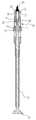
Translated fromKorean도 1은 본 발명에 따른 세포채취브러쉬의 사시도이고,1 is a perspective view of a cell harvesting brush according to the present invention,
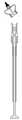
도 2는 도 1의 세포채취브러쉬의 분해사시도이고,Figure 2 is an exploded perspective view of the cell collection brush of Figure 1,
도 3은 도 1의 Ⅲ-Ⅲ 선에 따른 단면도이고,3 is a cross-sectional view taken along line III-III of FIG. 1,
도 4 및 도 5는 본 발명에 따른 세포채취브러쉬의 동작 상태를 설명하기 위한 단면도이다.4 and 5 are cross-sectional views for explaining the operating state of the cell collection brush according to the present invention.
* 도면의 주요 부분에 대한 부호의 설명* Explanation of symbols for the main parts of the drawings
10 : 파지부 30 : 세포채취부재10: gripping portion 30: cell harvesting member
50 : 내측 착탈부재 70 : 가동부재50: inner detachable member 70: movable member
본 발명은 액상세포를 이용한 자궁암 검진 세포채취브러쉬에 관한 것으로서, 보다 상세하게는 여성의 자궁 내부의 세포를 보다 용이하게 채취할 수 있는 세포채취브러쉬에 관한 것이다.The present invention relates to a uterine cancer screening cell collection brush using liquid cells, and more particularly to a cell collection brush that can more easily collect the cells inside the uterus of women.
여성이 갖는 특유의 질병 중 여성의 생식기 즉, 자궁과 관련된 질병이 여성 의 질병 발생에서 큰 비중을 차지하고 있는 것이 현실이다.Among women's unique diseases, the female genitalia, ie, uterine diseases, account for a large proportion of women's diseases.
이러한, 여성의 생식기 질병 중 흔히 발생하는 질병 중의 하나가 종양의 일종인 자궁경부암이다. 자궁경부암은 발병기전이 비교적 잘 알려진 종양으로, 성병의 일종인 인유두종 바이러스에 의해 발생한다. 성교시, 여성 생식기인 상피세포가 인유두종 바이러스에 의해 감염되면, 인유두종 바이러스의 DNA가 세포 핵 내의 DNA에 침투하여 증식하면서 상피세포암을 일으킨다.One of the most common diseases of female genital diseases is cervical cancer, which is a kind of tumor. Cervical cancer is a tumor of relatively well known pathogenesis and is caused by human papillomavirus, a type of sexually transmitted disease. During sexual intercourse, when epithelial cells, which are female genitals, are infected by the HPV virus, the DNA of the HPV penetrates into the DNA in the cell nucleus, causing epithelial cell carcinoma.
이러한, 인유두종 바이러스의 감염 여부를 검사하는 방법으로는 자궁 경부 세포진 도말법 등 여러가지 방법이 제안되고 있으나, 근래에는 중합효소 연쇄반응(PCR : Polymerase chain reaction) 검사방법을 이용하여 인유두종 바이러스 감염여부를 검사하고 있다. 이는 중합효소 연쇄반응 검사방법이 자궁경부암의 조기 진단용 선별 검사법 중 가장 민감하고 정확한 방법으로 인정받고 있기 때문이다.In order to test the infection of HPV, various methods such as cervical cytology smear method have been proposed, but recently, it is tested for HPV infection using a polymerase chain reaction (PCR) test method. Doing. This is because the polymerase chain reaction test is recognized as the most sensitive and accurate method of screening for the early diagnosis of cervical cancer.
이러한 중합효소 연쇄반응 검사방법의 사용을 위해서는 여성의 자궁, 특히 자궁경부의 세포를 채취하는 것이 필수적인데, 이와 같이 여성의 자궁경부에서 세포를 채취하기 위한 세포채취브러쉬가 다양한 형태로 제안되고 있다.In order to use the polymerase chain reaction test method, it is essential to collect cells of a woman's uterus, particularly the cervix. Thus, a cell collection brush for collecting cells from the woman's cervix has been proposed in various forms.
한국실용신안공개공보 제1999-1000001호(이하, '문헌 1'이라 함)에는 '자궁경부 질환 검진용 세포 채취구조'가 개시되어 있다. 상기 문헌에는 질 내부로 자궁경부 채취 기구를 삽입하여 자궁경부 세포를 채취하는 '자궁경부 세포채취브러쉬구'가 개시되어 있다.Korean Utility Model Publication No. 1999-1000001 (hereinafter referred to as 'Document 1') discloses a cell harvesting structure for cervical disease screening. The document discloses a 'cervical cell harvesting brush' for collecting cervical cells by inserting a cervical sampling device into the vagina.
그러나, 문헌 1에 개시된 '자궁경부 질환 검진용 세포 채취구조'는 손잡이의 양측에 각각 세포를 채취할 수 있는 외막채취구 및 내막채취구를 착탈 가능하게 함 으로써, 자궁경부의 외막 밍 내막을 각각 별도로 채취하여야 하는 불편함이 있다.However, the 'cell collection structure for cervical disease screening' disclosed in Document 1 enables detachable outer membrane collecting and inner lining collecting cells, which can collect cells on both sides of the handle, respectively, thereby dividing the outer lining of the cervix. There is inconvenience to be collected separately.
또한, 한국특허공개공보 제2004-82781호(이하, '문헌 2'라 함)에는 '자궁경부 세포 채취 기구'가 개시되어 있다. 문헌 2에는 실리콘으로 제조되는 채취대를 구비하고, 추가의 채취대를 더 포함하며, 길이 조절이 가능하도록 형성된 이음부를 구비하는 '자궁경부 세포 채취 기구'가 개시되어 있다.In addition, Korean Patent Publication No. 2004-82781 (hereinafter referred to as Document 2) discloses a 'cervical cell harvesting mechanism'. Document 2 discloses a 'cervical cell harvesting instrument' having a harvesting table made of silicon, further comprising an additional harvesting table, and having a joint formed to be adjustable in length.
그러나, 문헌 2에 개시된 '자궁경부 세포 채취 기구'는 길이 조절이 가능하다는 장점이 있으나, 세포를 채취하기 위해 채취부에 마련된 채취솔에만 의존하여 세포 채취 효율이 보장되지 않는 단점이 있다. 또한, 채취부의 길이방향에 대한 가로 방향으로 연장된 제2 채취부가 형성되어 '자궁경부 세포 채취 기구'가 여성의 질 내에 삽입될 때 질 내벽을 자극하여 통증을 유발하거나 자칫 질 내벽에 손상을 줄 우려가 있다.However, the 'cervical cell harvesting mechanism' disclosed in Document 2 has the advantage that the length can be adjusted, but there is a disadvantage that the cell harvesting efficiency is not guaranteed depending only on the sampling brush provided in the harvesting unit to collect the cells. In addition, a second collecting portion extending in the transverse direction with respect to the longitudinal direction of the collecting portion is formed to stimulate the inner wall of the vagina when the 'cervical cell harvesting mechanism' is inserted into the vagina of the woman, causing pain or damaging the inner wall There is concern.
또한, 중합효소 연쇄반응 검사방법의 이용을 위해, 채취된 세포는 세포 고정액이 수용된 소정의 용기에 담궈 보관하는 과정을 거치는 것이 일반적인데, 문헌 1 및 문헌 2에 개시된 세포채취브러쉬의 경우, 채취부를 시료자가 손이나 집게 등의 기구를 이용하여 세포채취브러쉬로부터 직접 분리하여야 하는 바, 채취부에 이물질이 포함될 우려가 있다. 이는, 정확한 세포의 채취에 의한 정확한 진단을 저해하는 요소로 작용한다.In addition, in order to use the polymerase chain reaction test method, it is common that the collected cells are stored in a predetermined container containing a cell fixative solution, and in the case of the cell collection brushes disclosed in Documents 1 and 2, The sampler should be separated directly from the cell collection brush using an instrument such as a hand or tongs, and there is a fear that foreign substances will be included in the collection part. This acts as a factor that inhibits accurate diagnosis by collecting accurate cells.
따라서, 본 발명의 목적은, 여성의 자궁경부 내부, 자궁 경질부 등 자궁경부의 다양한 위치의 세포를 여성의 질 내벽의 손상 없이 고루 채취할 수 있는 세포채 취브러쉬를 제공하는 것이다.Accordingly, an object of the present invention is to provide a cellular brush that can evenly collect cells at various positions of the cervix, such as the inside of the cervix of the woman and the cervix, without damaging the inner wall of the woman's vagina.
또한, 본 발명의 다른 목적은 채취된 세포를 보다 안전하게 소정의 수용 용기에 수용시켜 보관할 수 있게 함으로써, 보다 안정적이고 정확한 세포의 채취 및 진단을 보장할 수 있는 세포채취브러쉬를 제공하는 것이다.In addition, another object of the present invention is to provide a cell collection brush that can ensure the collection and diagnosis of more stable and accurate cells by allowing the collected cells to be stored more safely in a predetermined container.
상기 목적은, 본 발명에 따라, 여성의 자궁 내부의 세포를 채취하기 위한 세포채취브러쉬에 있어서, 일측에 걸림턱이 형성된 삽입부를 가지며, 내부에 슬라이딩 공간이 형성된 파지부와; 다수의 채취돌기와 제1 후크 걸림부와 제2 후크 걸림부가 형성된 제1 채취부와, 상기 제1 채취부로부터 상기 파지부의 길이방향으로 연장 형성되며 상기 파지부의 길이방향을 따라 신축 가능한 제2 채취부와, 상기 제2 채취부의 상기 파지부 방향에 상기 제2 채취부와 일체로 형성된 제1 결합부를 갖는 세포채취부재와; 상기 파지부의 상기 걸림턱에 걸림 및 걸림 해제되어 상기 파지부에 착탈 가능한 제2 결합부와, 상기 제1 채취부에 형성된 상기 제1 후크 걸림부에 걸림 가능한 제1 후크부와, 상기 제2 결합부와 상기 제1 후크부를 연결하는 연결부재를 갖는 내측 착탈부재와; 상기 세포채취부재 측 단부에 상기 제2 후크 걸림부에 걸림 및 걸림 해제 가능한 제2 후크부가 마련되고, 상기 제2 후크부가 상기 제2 후크 걸림부에 걸리는 제1 걸림위치에서 상기 제2 후크부가 상기 제2 후크 걸림부에 걸림 유지된 상태에서 상기 제2 채취부가 수축하여 상기 제1 채취부가 상기 제1 결합부에 접근함에 따라 상기 제1 후크부가 상기 제1 후크 걸림부에 걸리는 제2 걸림위치로 슬라이딩 이동 가능하도록 상기 파지부에 수용되는 가동부재를 포함하는 것 을 특징으로 하는 세포채취브러쉬에 의해 달성된다.According to the present invention, in the cell collection brush for collecting the cells inside the uterus of the woman, having a holding portion formed with a locking jaw on one side, the holding portion formed with a sliding space therein; A first collecting part including a plurality of collecting protrusions, a first hook locking part, and a second hook locking part; a second extension extending from the first collecting part in a length direction of the grip part and being stretchable along a length direction of the holding part; A cell collecting member having a collecting part and a first coupling part integrally formed with the second collecting part in a direction of the holding part of the second collecting part; A second coupling part which is caught and released by the holding jaw of the gripping part and is detachable from the gripping part, a first hook part which can be caught by the first hook locking part formed on the first collecting part, and the second An inner detachable member having a coupling member connecting to the coupling part and the first hook; A second hook portion capable of engaging and releasing the second hook engaging portion is provided at an end portion of the cell collecting member, and the second hook portion is disposed at a first locking position where the second hook portion is caught by the second hook engaging portion. The second catching portion contracts while being held in a second hook catching portion, so that the first catching portion is caught in the first hook catching portion as the first catching portion approaches the first engaging portion. It is achieved by a cell harvesting brush, characterized in that it comprises a movable member accommodated in the gripping portion to enable sliding movement.
여기서, 상기 내측 착탈부재의 상기 제2 결합부는 상기 가동부재가 상기 파지부의 길이방향을 따라 관통하는 통과공이 형성된 대략 통 형상을 가지며; 상기 내측 착탈부재의 상기 연결부재는 양 단부가 상기 제2 결합부와 연결되며 골 영역에 상기 제1 후크부가 상기 제1 후크 걸림부를 향해 형성된 대략 V 빔 형상을 가질 수 있다.Wherein the second engaging portion of the inner detachable member has a substantially cylindrical shape in which a through hole through which the movable member penetrates along the longitudinal direction of the gripping portion is formed; The connecting member of the inner detachable member may have an approximately V beam shape in which both ends thereof are connected to the second coupling part, and the first hook part is formed toward the first hook engaging part in a valley area.
그리고, 상기 세포채취부재의 제2 채취부는 상기 파지부의 길이방향의 축을 중심으로 하는 원주 방향을 따라 상호 소정 간격 이격되어 상기 제1 채취부와 상기 제1 결합부를 연결하는 복수의 채취빗살을 포함하며; 상기 복수의 채취빗살은 상기 가동부재가 상기 제1 걸림위치에서 상기 제2 걸림위치로 슬라이딩 이동시 상기 제1 채취부가 상기 제1 결합부로 접근하도록 상기 파지부의 길이방향의 축 외측으로 방사상으로 탄성적으로 구부러져 수축할 수 있다.The second collecting part of the cell collecting member includes a plurality of collecting combs connecting the first collecting part and the first coupling part to be spaced apart from each other by a predetermined interval along a circumferential direction around the longitudinal axis of the gripping part. To; The plurality of collecting combs are radially elastically outward in the longitudinal axis of the gripping portion such that the first sampling portion approaches the first engaging portion when the movable member slides from the first locking position to the second locking position. Can be bent and contracted.
또한, 상기 세포채취부재의 상기 제1 결합부에는 상기 가동부재의 상기 제1 걸림위치 및 상기 제2 걸림위치에서 상기 내측 착탈부재의 상기 제2 결합부가 삽입되는 삽입공이 형성될 수 있다.In addition, an insertion hole into which the second coupling portion of the inner detachable member is inserted may be formed in the first coupling portion of the cell collection member at the first locking position and the second locking position of the movable member.
그리고, 상기 제1 결합부의 상기 삽입공 내벽과 상기 제2 결합부의 외벽 중 어느 일측에는 상기 파지부의 길이방향을 따라 돌출된 제1 가이드 리브가 형성되고; 상기 제1 결합부의 상기 상입공 내벽과 상기 제2 결합부의 외벽 중 타측에는 상기 상기 제2 결합부가 상기 제1 결합부의 상기 삽입공에 삽입시 상기 제1 가이드 리브를 안내하는 제1 가이드 홈이 형성될 수 있다.A first guide rib protruding along the longitudinal direction of the gripping portion is formed on one side of the inner wall of the insertion hole and the outer wall of the second coupling portion of the first coupling portion; A first guide groove for guiding the first guide rib when the second coupling portion is inserted into the insertion hole of the first coupling portion is formed at the other side of the inner wall of the first coupling portion and the outer wall of the second coupling portion. Can be.
또한, 상기 가동부재의 상기 세포채취부재 측 단부 영역은 양 측으로 갈라진 대략 V자 형 연장 가지가 형성되며; 상기 제2 후크부는 상기 각 연장 가지의 단부 영역에 반대측 연장 가지를 향태 돌출 형성될 수 있다.Further, the cell collecting member side end region of the movable member is formed with approximately V-shaped extension branches which are split to both sides; The second hook portion may be formed to protrude from the extension branch opposite to the end region of each extension branch.
그리고, 상기 내측 착탈부재의 상기 제2 결합부의 내면에는 상기 파지부의 길이방향을 따라 상기 제2 가이드 리브가 마련되며; 상기 파지부의 상기 삽입부에는 상기 삽입부가 상기 내측 착탈부재의 상기 제2 결합부에 삽입될 때 상기 제2 가이드 리브가 슬라이딩 삽입 안내되는 제2 가이드 홈과, 상기 파지부의 길이방향을 따라 상기 가동부재의 상기 각 연장 가지의 이동을 안내하는 제3 가이드 홈이 형성될 수 있다.The second guide rib is provided on an inner surface of the second coupling part of the inner detachable member along a longitudinal direction of the gripping part; The insertion portion of the gripping portion has a second guide groove in which the second guide rib is slidingly inserted and guided when the insertion portion is inserted into the second engagement portion of the inner detachable member, and the movable portion along the longitudinal direction of the gripping portion. A third guide groove may be formed to guide the movement of each of the extension branches of the member.
여기서, 상기 가동부재는 상기 제2 걸림위치에서 상기 제2 후크부가 상기 세포채취부재의 상기 제2 후크 걸림부로부터 걸림 해제되고 상기 내측 착탈부재의 상기 제2 결합부의 상기 통과공을 상기 세포채취부재 측으로부터 상기 파지부 측으로 통과하여 상기 파지부의 상기 슬라이딩 공간에 수용되는 걸림해제위치로 슬라이딩 이동 가능하게 마련될 수 있다.Here, the movable member is the second hook portion is released from the second hook engaging portion of the cell collecting member in the second locking position and the through hole of the second coupling portion of the inner detachable member of the cell collecting member Passing from the side to the gripping portion side may be provided to be slidably movable to the unlocking position accommodated in the sliding space of the gripping portion.
그리고, 상기 가동부재의 상기 연장 가지의 단부에는 상기 걸림해제위치에서 상기 세포채취부재 측으로 슬라이딩 이동시 상기 내측 착탈부재의 상기 제2 결합부의 상기 파지부 측 단부를 가압하는 가압부가 마련되며; 상기 가압부가 상기 제1 결합부를 소정 힘 이상으로 가압하는 경우, 상기 파지부의 상기 걸림턱이 상기 내측 착탈부재의 상기 제2 결합부로부터 걸림 해제되어 상기 세포채취부재 및 상기 내측 착탈부재가 상기 파지부로부터 분리될 수 있다.And, the end of the extension branch of the movable member is provided with a pressing portion for pressing the end portion of the holding portion side of the second engaging portion of the inner detachable member when the sliding movement from the latch release position to the cell collecting member side; When the pressing portion presses the first coupling portion by a predetermined force or more, the locking jaw of the gripping portion is released from the second coupling portion of the inner detachable member so that the cell collection member and the inner detachable member are separated from the wave. It can be separated from the branch.
또한, 상기 가동부재의 상기 연장 가지의 적어도 일측에는 상기 제2 걸림위치에서 상기 걸림해제위치로의 슬라이딩 이동시 상기 연장 가지를 상호 접근하여 상기 연장 가지의 단부가 상기 내측 착탈부재의 상기 통과공을 통과 가능하도록 상기 파지부의 상기 제3 가이드 홈의 내벽에 접촉 가압되는 경사면이 마련될 수 있다.Further, at least one side of the extension branch of the movable member approaches the extension branch when sliding from the second locking position to the unlocking position so that the end of the extension branch passes through the through hole of the inner detachable member. An inclined surface may be provided to be in contact with the inner wall of the third guide groove of the gripping portion.
그리고, 상기 내측 착탈부재는 상기 제2 결합부으로부터 외측으로 연장 형성되어 상기 제2 걸림위치에서 상기 제2 채취부의 탄성력에 의한 상기 제1 결합부의 상기 파지부 측으로의 후퇴를 저지하는 하는 것을 저지하는 저지플랜지부를 더 포함할 수 있다.The inner detachable member extends outwardly from the second engaging portion to prevent the retraction of the first engaging portion to the gripping portion by the elastic force of the second collecting portion at the second locking position. It may further include a jersey flange.
이하에서는 첨부한 도면을 참조하여 본 발명을 상세히 설명한다.Hereinafter, with reference to the accompanying drawings will be described in detail the present invention.
본 발명에 따른 세포채취브러쉬(1)는, 도 1 내지 도 3에 도시된 바와 같이, 파지부(10), 세포채취부재(30), 내측 착탈부재(50) 및 가동부재(70)를 포함한다. 여기서, 세포채취부재(30)가 위치하는 방향, 즉 여성의 생식기로 삽입되는 방향을 제1 방향이라 하고, 제1 방향의 반대 방향을 제2 방향이라 임의로 정의하여 설명한다.Cell collection brush 1 according to the present invention, as shown in Figures 1 to 3, the
파지부(10)는 내부에 슬라이딩 공간(15)이 형성된 대략 통 형상의 긴 막대 형상을 갖는다. 여기서, 파지부(10)는 시료자가 여성의 자궁으로부터 세포를 채취할 때, 파지하는 부분으로 일정 영역은 여성의 생식기 내부로 삽입될 수 있다.The gripping
파지부(10)는 걸림턱(12)이 형성된 삽입부(11)를 포함한다. 삽입부(11)는 파지부(10)의 제1 방향 측 단부 영역에 형성되며, 단면이 대략 원형을 가질 수 있 다.The gripping
삽입부(11)의 제1 방향 측 단부 영역에 형성된 걸림턱(12)은 삽입부(11)의 단부 영역으로부터 외측으로 연장 돌출되어 형성된다. 여기서, 걸림턱(12)은 내측 착탈부재(50)의 제2 결합부(52)에 걸림 및 걸림 해제됨으로써, 내측 착탈부재(50)가 파지부(10)에 착탈 가능하게 결합되도록 한다.The
세포채취부재(30)는 본 발명에 따른 세포채취부재(30)가 여성의 생식기 내부에 삽입될 때, 자궁경부의 다양한 영역, 예컨대, 자궁경부 내벽, 자궁 경질부 등 자궁경부의 다양한 영역의 세포를 채취한다. 여기서, 본 발명에 따른 세포채취부재(30)는 제1 채취부(31), 제2 채취부(35) 및 제1 결합부(37)를 포함할 수 있다.The
제1 채취부(31)에는 다수의 채취돌기(32), 제1 후크 걸림부(33) 및 제2 후크 걸림부(34)가 형성된다. 제1 채취부(31)의 채취돌기(32)는 본 발명에 따른 세포채취부재(30)가 여성의 생식기 내부에 삽입될 때, 자궁경부의 내벽 및 자궁 경질부의 세포를 채취하게 된다.A plurality of
또한, 제1 후크 걸림부(33)에는 내측 착탈부재(50)의 후술할 제1 후크부(51)가 걸림 및 걸림 해제된다. 여기서, 제1 후크 걸림부(33)에는 내측 착탈부재(50)의 제1 후크부(51)가 파지부(10)의 길이방향을 따라 삽입 및 인출되어 걸림 및 걸림 해제된다.In addition, the first
그리고, 제2 후크 걸림부(34)에는 가동부재(70)의 제2 후크부(71)가 걸림 및 걸림 해제된다. 여기서, 제2 후크 걸림부(34)에는 가동부재(70)의 제2 후크부(71)가 외측으로부터 내측으로 걸림 및 걸림 해제된다.Then, the
제2 채취부(35)는 제1 채취부(31)로부터 파지부(10)의 길이방향으로 연장 형성된다. 여기서, 제2 채취부(35)는 길이방향을 따라 탄성적으로 신축 가능하게 마련되어 수축시 제1 채취부(31)를 제1 결합부(37)에 접근시킨다.The
제1 결합부(37)는 내측 착탈부재(50)의 후술할 제2 결합부(52)가 삽입되는 삽입공(38)이 형성된 대략 통 형상을 갖는다.The
여기서, 본 발명에 따른 제2 채취부(35)는 파지부(10)의 길이방향의 축을 중심으로 하는 원주 방향을 따라 상호 소정 간격 이격된 복수의 채취빗살(36)을 포함할 수 있다. 채취빗살(36)은 제1 채취부(31)와 제1 결합부(37)를 상호 연결하며, 후술할 가동부재(70)의 슬라이딩에 따라 제1 채취부(31)가 제1 결합부(37) 측으로 접근할 때, 파지부(10)의 길이방향의 축 외측으로 방사상으로 탄성적으로 구부러져 수축한다(도 4 참조). 여기서, 제2 채취부(35)의 채취빗살(36)이 탄성적으로 구부러진 상태에서 시료자가 본 발명에 따른 세포채취브러쉬(1)를 파지부(10)의 길이방향의 축을 따라 회전시키는 경우 채취빗살(36)에 의해 자궁경부의 자궁 경질부의 세포가 용이하게 채취될 수 있다.Here, the
한편, 본 발명에 따른 내측 착탈부재(50)는 제2 결합부(52), 제1 후크부(51) 및 연결부재(56)를 포함할 수 있다.On the other hand, the inner
제1 후크부(51)는, 전술한 바와 같이, 세포채취부재(30)의 제1 채취부(31)에 형성된 제1 후크 걸림부(33)에 걸림 및 걸림 해제된다. 여기서, 제1 후크부(51)가 제1 후크 걸림부(33)에 걸림 유지되는 경우 세포채취부재(30)와 내측 착탈부재(50)는 함께 움직이게 된다.As described above, the
제2 결합부(52)는 파지부(10)의 삽입부(11)에 형성된 걸림턱(12)에 걸림 및 걸림 해제됨으로써, 내측 착탈부재(50)가 파지부(10)의 삽입부(11)에 착탈 가능하게 한다. 여기서, 제2 결합부(52)는 가동부재(70)가 파지부(10)의 길이방향을 따라 통과 가능하도록 통과공(53)이 형성된 대략 통 형상을 갖는다.The
그리고, 제2 결합부(52)는 세포채취부재(30)의 제1 결합부(37)의 삽입공(38)에 삽입되어 세포채취부재(30)와 결합된다. 여기서, 제2 결합부(52)의 외벽에는 파지부(10)의 길이방향을 따라 외측으로 돌출된 적어도 하나의 제1 가이드 리브(54)가 형성될 수 있다. 이에 대응하여, 세포채취부재(30)의 제1 결합부(37)의 삽입공(38) 내벽에는 제2 결합부(52)가 제1 결합부(37)의 삽입공(38)에 삽입될 때 제1 가이드 리브(54)가 삽입되어 안내되는 제1 가이드 홈(39)이 형성될 수 있다. 이에 따라, 제2 결합부(52)가 제1 결합부(37)에 안정적으로 삽입되는 것을 보장하고, 세포채취부재(30)와 내측 착탈부재(50)가 상호 독립적으로 회전하는 것을 방지할 수 있다. 여기서, 제2 결합부(52)의 외벽에 제1 가이드 홈(39)이 형성되고 제1 결합부(37)의 내벽에 제1 가이드 리브(54)가 형성될 수도 있음은 물론이다..Then, the
연결부재(56)는 제1 후크부(51)와 제2 결합부(52)를 상호 연결한다. 여기서, 연결부재(56)는 양 단부가 제2 결합부(52)에 연결되는 대략 V 빔 형상을 갖는다. 그리고, 제1 후크부(51)는 V 빔의 골 영역으로부터 세포채취부재(30)의 제1 후크 걸림부(33)를 향해 형성된다.The
본 발명에 따른 가동부재(70)에는 제1 방향 측 단부에 세포채취부재(30)의 제2 후크 걸림부(34)에 걸림 및 걸림 해제 가능한 제2 후크부(71)가 마련된다. 그 리고, 가동부재(70)는 제1 걸림위치와 제2 걸림위치 간을 슬라이딩 가능하도록 파지부(10)에 수용된다.The
여기서, 제1 걸림위치는 가동부재(70)의 제2 후크부(71)가 세포채취부재(30)의 제2 후크 걸림부(34)에 걸리는 위치를 의미하며, 제2 걸림위치는 제2 후크부(71)가 제2 후크 걸림부(34)에 걸림 유지된 상태에서 제2 채취부(35)가 수축여 제1 채취부(31)가 제1 결합부에 접근함에 따라 내측 착탈부재(50)의 제1 후크부(51)가 세포채취부재(30)의 제1 후크 걸림부(33)에 걸리는 위치를 의미한다.Here, the first locking position means a position where the
즉, 제1 걸림위치에서는 세포채취부재(30)의 제2 채취부(35)의 채취빗살(36)이 펴진 상태이고, 제2 걸림위치에서는 세포채취부재(30)의 제2 채취부(35)의 채취빗살(36)이 방사상으로 구부러진 상태이다. 여기서, 내측 착탈부재(50)는 제2 결합부(52)으로부터 외측으로 연장 형성되어 제2 걸림위치에서 제2 채취부(35)의 탄성력에 의한 제1 결합부(37)의 파지부(10) 측으로의 후퇴를 저지하는 저지플랜지부(57)를 포함하게 된다. 이에 따라, 제2 걸림위치에서 내측 착탈부재(50)의 제1 후크부(51)가 세포채취부재(30)의 제1 후크 걸림부(33)에 걸림 유지되고, 내측 착탈부재(50)의 저지플랜지부(57)가 세포채취부재(30)의 제1 결합부(37)의 후퇴를 저지함으로써, 세포채취부재(30)의 채취빗살(36)이 도 4에 도시된 바와 같이 방사상으로 구부러진 형상을 유지할 수 있게 된다.That is, in the first locking position, the collecting
한편, 가동부재(70)의 제1 방향 측 단부 영역에는 양 측이 갈라진 대략 V자 형 연장 가지(72)가 형성될 수 있다. 여기서, 가동부재(70)의 제2 후크부(71)는 각 연장 가지(72)의 단부 영역에 반대측 연장 가지(72)를 향해 돌출 형성될 수 있 다. 이에 따라, 전술한 바와 같이, 가동부재(70)가 제1 걸림위치로부의 진입시 세포취출부재의 제1 채취부(31)의 양측에 형성된 제2 후크 걸림부(34)에 외측으로부터 내측으로 걸릴 수 있게 된다.On the other hand, in the first direction side end region of the
한편, 본 발명에 따른 내측 착탈부재(50)의 제2 결합부(52)의 내면에는 파지부(10)의 길이방향을 따라 제2 가이드 리브(55)가 형성될 수 있다. 이에 대응하여, 파지부(10)의 삽입부(11)에는 삽입부(11)가 내측 착탈부재(50)의 제2 결합부(52)에 삽입될 때, 제2 가이드 리브(55)의 슬라이딩 삽입을 안내하는 제2 가이드 홈(13)이 형성될 수 있다. 이에 따라, 파지부(10)와 내측 착탈부재(50)가 결합될 때 파지부(10)의 삽입부(11)가 내측 착탈부재(50)의 제2 결합부(52)에 안정적으로 삽입되는 것을 보장하고, 내측 착탈부재(50)와 파지부(10)가 상호 독립적으로 회전하는 것을 방지할 수 있다.Meanwhile, a
또한, 파지부(10)의 삽입부(11)에는 파지부(10)의 길이방향을 따라 가동부재(70)의 각 연장 가지(72)의 슬라이딩 이동을 안내하는 제3 가이드 홈(14)이 형성될 수 있다.In addition, a
한편, 본 발명에 따른 가동부재(70)는 제2 걸림위치에서 제2 후크부(71)가 세포채취부재(30)의 제2 후크 걸림부(34)로부터 걸림 해제되고 내측 착탈부재(50)의 제2 결합부(52)의 통과공(53)을 제1 방향으로부터 제2 방향으로 통과하여 파지부(10)의 슬라이딩 공간(15)에 수용되는 걸림해제위치로 슬라이딩 이동할 수 있다.On the other hand, in the
여기서, 가동부재(70)의 연장 가지(72) 단부에는 시료자가 가동부재(70)를 걸림해제위치에서 제1 방향으로 슬라이딩 이동시키는 경우, 내측 착탈부재(50)의 제2 결합부(52)의 제1 방향 측 단부를 가압하는 가압부(73)를 포함하게 된다.Here, when the sampler slides the
이 때, 시료자가 걸림해제위치에서 가동부재(70)를 제1 방향으로 소정 힘 이상으로 가압하는 경우, 파지부(10)의 삽입부(11)에 형성된 걸림턱(12)이 내측 착탈부재(50)의 제2 결합부(52)로부터 걸림 해제되어 내측 착탈부재(50)가 세포채취부재(30)와 결합된 상태로 파지부(10)로부터 분리된다. 이에 따라, 시료자는 세포의 채취 후 세포채취부재(30)를 손이나 기타 기구를 사용하지 않고 파지부(10)로부터 분리할 수 있게 된다. 여기서, 전술한 바와 같이, 내측 착탈부재(50)의 제1 후크부(51)가 세포채취부재(30)의 제1 후크 걸림부(33)에 걸림 유지되고, 내측 착탈부재(50)의 저지플랜지부(57)가 세포채취부재(30)의 제1 결합부(37)의 후퇴를 저지하고 있는 상태인 바, 내측 착탈부재(50) 및 세포채취부재(30)는 도 5에 도시된 바와 같은 형상을 유지하며 파지부(10)로부터 분리될 수 있다.At this time, when the sampler presses the
이하에서는, 도 3 내지 도 5을 참조하여 본 발명에 따른 세포채취브러쉬(1)를 이용한 자궁경부의 세포 채취 과정을 상세히 설명한다.Hereinafter, with reference to Figures 3 to 5 will be described in detail the cell collection process of the cervix using the cell collection brush (1) according to the present invention.
먼저, 자궁경부의 세포를 채취하기 전에 본 발명에 따른 세포채취브러쉬(1)의 가동부재(70)는, 도 3에 도시된 바와 같이, 제1 걸림위치에 위치한 상태로 유지될 수 있다. 이외에도, 가동부재(70)는 제1 걸림위치로의 진입 전 단계로 유지될 수 있으며, 시료자가 가동부재(70)를 제1 방향으로 가압하여 가동부재(70)가 제1 걸림위치로 진입될 수도 있다. 이 경우, 가동부재(70)의 제1 방향 측 단부 영역, 즉 제2 후크부(71)가 설치된 부분은 제1 걸림위치로의 진입 전 단계에서 세포채취부재(30)의 제2 후크 걸림부(34)와 내측 착탈부재(50)의 제2 결합부(52) 사이에 위 치하게 된다.First, before collecting the cells of the cervix, the
여기서, 제1 걸림위치에서는 파지부(10)의 삽입부(11)가 내측 착탈부재(50)의 제2 결합부(52)에 형성된 통과공(53)에 삽입되어 걸림턱(12)이 내측 착탈부재(50)의 제2 결합부(52)에 걸림 유지된 상태이고, 내측 착탈부재(50)의 제2 결합부(52)가 세포채취부재(30)의 제1 결합부(37)에 삽입된 상태이다.Here, in the first locking position, the
그런 다음, 시료자는 가동부재(70)가 제1 걸림위치인 상태로 본 발명에 따른 세포채취브러쉬(1)를 여성의 생식기에 삽입한다. 여기서, 세포채취부재(30)의 제2 채취부(35)가, 도 3에 도시된 바와 같이, 펴진 상태에서 여성의 생식기 내부로 삽입됨으로서, 여성의 생식기, 예컨대 질 내벽의 손상 없이 세포채취브러쉬(1)를 자궁경부 측까지 삽입할 수 있게 된다.Then, the sampler inserts the cell collection brush 1 according to the present invention into the female genitalia with the
그런 다음, 시료자는 파지부(10)의 제2 방향 측으로 노출된 가동부재(70)를 제2 방향 측으로 잡아 당겨 가동부재(70)가 제1 걸림위치에서 제2 걸림위치로 슬라이딩 이동하도록 한다. 이 때, 세포채취부재(30)의 제1 채취부(31)는 제2 채취부(35)의 탄성적 수축에 의해 제1 결합부(37) 측으로 접근하게 되고, 제1 채취부(31)가 제1 결합부(37)로 접근하는 중에 내측 착탈부재(50)의 제1 후크부(51)가 세포채취부재(30)의 제1 후크 걸림부(33)에 걸리게 되는 제2 걸림위치로 진입하게 된다. 이 경우, 세포채취부재(30)의 제2 채취부(35)는 도 4에 도시된 바와 같이 방사상으로 탄성적으로 구부러지게 된다.Then, the sampler pulls the
그런 다음, 시료자는 본 발명에 따른 세포채취브러쉬(1)가 도 4에 도시된 상태, 즉 가동부재(70)가 제2 걸림위치인 상태에서, 세포채취부재(30)의 제1 채취부 (31)가 자궁경부에 삽입되도록 한다. 이 경우, 세포채취부재(30)의 제2 채취부(35)는 방사상으로 구부러진 상태로 자궁경부 내부에 삽입되지 않고 자궁 경질부의 질측 벽에 밀착된다.Then, the sampler is the first collecting portion of the
여기서, 시료자는 세포채취부재(30)의 제2 채취부(35)가 자궁경부 내부에 삽입되고 제2 채취부(35)가 자궁 경질부의 질측 벽에 밀착된 상태에서, 세포채취브러쉬(1)를 회전시킴으로서, 제1 채취부(31)에 의해 자궁경부 내부의 세포가 채취되고 제2 채취부(35)의 채취빗살(36)의 회전에 의해 자궁 경질부의 질측 벽의 세포가 채취되게 한다. 이에 따라, 자궁경부 내부 및 자궁 경질부 등의 자궁경부의 다양한 영역의 세포가 채취 가능하게 된다.Here, the sample is a cell collection brush (1) in a state that the
한편, 시료자는 자궁경부의 세포 채취가 완료된 경우, 세포채취브러쉬(1)를 여성의 자궁으로부터 빼낸다. 그런 다음, 시료자는 파지부(10)의 제2 방향 측으로 노출된 가동부재(70)를 제2 방향으로 소정 힘 이상으로 잡아 당김으로서 가동부재(70)를 걸림해제위치로 이동시킨다.On the other hand, the sampler pulls out the cell collection brush 1 from the uterus of the woman when the cell collection of the cervix is completed. Then, the sampler moves the
이 때, 사용자가 소정 힘 이상으로 가동부재(70)를 제2 방향 측으로 잡아 당기는 경우, 가동부재(70)의 제2 후크부(71)가 세포채취부재(30)의 제1 채취부(31)에 형성된 제2 후크 걸림부(34)로부터 걸림 해제되어 내측 착탈부재(50)의 제2 결합부(52)의 통과공(53)을 통과하여 파지부(10) 측으로 이동한다.At this time, when the user pulls the
이 경우, 가동부재(70)의 연장 가지(72)의 적어도 일측은 걸림해제위치로의 슬리이딩 이동시 파지부(10)의 제3 가이드 홈(14)의 내벽에 접촉 가압되어 연장 가지(72)가 상호 접근하게 된다. 여기서, 가동부재(70)의 연장 가지(72)의 적어도 일측에는 제3 가이드 홈(14)의 내벽에 의해 접촉 가압되어 연장 가지(72)가 상호 용이하게 접근하도록 경사면(74)이 형성되는 것이 바람직하다. 이에 따라, 가동부재(70)의 연장 가지(72)가 내측 착탈부재(50)의 통과공(53)을 용이하게 통과하게 된다.In this case, at least one side of the
그런 다음, 시료자는 가동부재(70)를 걸림해제위치로 이동시킨 후, 파지부(10)의 제2 방향 측으로 노출된 가동부재(70)를 제1 방향 측으로 밀어 가동부재(70)의 가압부(73)가 내측 착탈부재(50)의 제2 결합부(52)를 가압하게 함으로써, 파지부(10)의 삽입부(11)에 형성된 걸림턱(12)이 내측 착탈부재(50)의 제2 결합부(52)로부터 걸림 해제되어 내측 착탈부재(50)가 파지부(10)로부터 분리되게 한다. 이에 따라, 내측 착탈부재(50)는 세포채취부재(30)와 결합된 상태로 파지부(10)에서 함께 분리된다. 이 때, 시료자는 내측 착탈부재(50)를 분리할 때, 세포채취부재(30)와 내측 착탈부재(50)를 보관하기 위한 용기의 입구 측에 세포채취부재(30) 및 내측 착탈부재(50)를 위치시킨 후 가동부재(70)를 제1 방향 측으로 밀어서 세포채취부재(30) 및 내측 착탈부재(50)가 용기에 바로 수용되도록 함으로써, 세포채취부재(30)나 내측 착탈부재(50)를 용기에 수용시키기 위한 별도의 별도의 기구나 시료자의 손을 거치지 않게 된다. 이에 따라, 보다 안정적이고 정확한 세포의 채취 및 진단을 보장할 수 있게 된다.Then, the sampler moves the
또한, 세포채취부재(30) 및 내측 착탈부재(50)가 제거된 파지부(10) 및 가동부재(70)에는 다른 세포채취부재(30) 및 내측 착탈부재(50)를 결합시켜 재 사용할 수 있게 된다.In addition, the
비록 본 발명의 몇몇 실시예들이 도시되고 설명되었지만, 본 발명이 속하는 기술분야의 통상의 지식을 가진 당업자라면 본 발명의 원칙이나 정신에서 벗어나지 않으면서 본 실시예를 변형할 수 있음을 알 수 있을 것이다. 그리고, 발명의 범위는 첨부된 청구항과 그 균등물에 의해 정해질 것이다.Although some embodiments of the invention have been shown and described, it will be apparent to those skilled in the art that modifications may be made to the embodiment without departing from the spirit or spirit of the invention. . The scope of the invention will be defined by the appended claims and equivalents thereof.
상기의 구성에 따라, 본 발명에 따르면, 여성의 자궁경부 내부, 자궁 경질부 등 자궁경부의 다양한 위치의 세포를 여성의 질 내벽의 손상 없이 고루 채취할 수 있는 세포채취브러쉬가 제공된다. 또한, 본 발명에 따르면, 채취된 세포를 보다 안전하게 소정의 수용 용기에 수용시켜 보관할 수 있게 함으로써, 보다 안정적이고 정확한 세포의 채취 및 진단을 보장할 수 있는 세포채취브러쉬가 제공된다.According to the above configuration, according to the present invention, there is provided a cell collection brush that can evenly collect cells of various positions of the cervix, such as the inside of the cervix of the woman, the cervix, without damaging the inner wall of the woman. In addition, according to the present invention, by allowing the collected cells to be stored more safely in a predetermined receiving container, there is provided a cell collection brush that can ensure the collection and diagnosis of more stable and accurate cells.
Claims (11)
Translated fromKoreanPriority Applications (7)
| Application Number | Priority Date | Filing Date | Title |
|---|---|---|---|
| KR1020050025666AKR100766340B1 (en) | 2005-03-28 | 2005-03-28 | Uterine Cancer Screening Cell Using Liquid Cells |
| EP11171195AEP2388567A1 (en) | 2005-03-28 | 2006-03-28 | Supporting solution for cytological diagnosis |
| CN200910223827ACN101864473A (en) | 2005-03-28 | 2006-03-28 | A supporting solution for cytological diagnosis |
| JP2008503940AJP2008534005A (en) | 2005-03-28 | 2006-03-28 | Tumor screening system, collection vial for liquid cytology (LBC), brush for cervical cancer liquid cytology (LBC), and supporting solution for cytology |
| PCT/KR2006/001124WO2006104333A1 (en) | 2005-03-28 | 2006-03-28 | Tumor screening system, collection vial for liquid based cytology, brush for liquid based cytology of cervix carcinoma and supporting solution for cytological diagnosis |
| EP06732717AEP1877771B1 (en) | 2005-03-28 | 2006-03-28 | Tumor screening system |
| AT06732717TATE545862T1 (en) | 2005-03-28 | 2006-03-28 | TUMOR SCREENING SYSTEM |
Applications Claiming Priority (1)
| Application Number | Priority Date | Filing Date | Title |
|---|---|---|---|
| KR1020050025666AKR100766340B1 (en) | 2005-03-28 | 2005-03-28 | Uterine Cancer Screening Cell Using Liquid Cells |
Publications (2)
| Publication Number | Publication Date |
|---|---|
| KR20060103768A KR20060103768A (en) | 2006-10-04 |
| KR100766340B1true KR100766340B1 (en) | 2007-10-11 |
Family
ID=37623641
Family Applications (1)
| Application Number | Title | Priority Date | Filing Date |
|---|---|---|---|
| KR1020050025666AExpired - Fee RelatedKR100766340B1 (en) | 2005-03-28 | 2005-03-28 | Uterine Cancer Screening Cell Using Liquid Cells |
Country Status (1)
| Country | Link |
|---|---|
| KR (1) | KR100766340B1 (en) |
Cited By (1)
| Publication number | Priority date | Publication date | Assignee | Title |
|---|---|---|---|---|
| KR20160062884A (en)* | 2014-11-26 | 2016-06-03 | (주) 메디포유 | Tool for gathering sample of uterine cervix |
Families Citing this family (5)
| Publication number | Priority date | Publication date | Assignee | Title |
|---|---|---|---|---|
| WO2014189130A1 (en)* | 2013-05-24 | 2014-11-27 | ニプロ株式会社 | Cell collection device |
| KR101504264B1 (en)* | 2014-08-11 | 2015-03-25 | 신기술 주식회사 | Medical discrete type brush |
| CN107811657B (en)* | 2017-11-23 | 2024-06-04 | 北京海普威生物技术有限公司 | Cervical cell sampling brush |
| KR102116515B1 (en)* | 2018-01-09 | 2020-05-28 | 유펙스메드 주식회사 | Biopsy brushes and biopsy catheters kit containing them |
| KR102009522B1 (en)* | 2019-02-21 | 2019-08-09 | (주)바이오다인 | collection device of exfoliative cells for womb screening |
Citations (2)
| Publication number | Priority date | Publication date | Assignee | Title |
|---|---|---|---|---|
| US20020087095A1 (en) | 1998-03-03 | 2002-07-04 | Senorx, Inc. | Methods and apparatus for securing medical instruments to desired locations in a patient's body |
| KR200361379Y1 (en) | 2004-06-23 | 2004-09-13 | 주식회사 기성 | Apparatus for picking of cell |
- 2005
- 2005-03-28KRKR1020050025666Apatent/KR100766340B1/ennot_activeExpired - Fee Related
Patent Citations (2)
| Publication number | Priority date | Publication date | Assignee | Title |
|---|---|---|---|---|
| US20020087095A1 (en) | 1998-03-03 | 2002-07-04 | Senorx, Inc. | Methods and apparatus for securing medical instruments to desired locations in a patient's body |
| KR200361379Y1 (en) | 2004-06-23 | 2004-09-13 | 주식회사 기성 | Apparatus for picking of cell |
Cited By (2)
| Publication number | Priority date | Publication date | Assignee | Title |
|---|---|---|---|---|
| KR20160062884A (en)* | 2014-11-26 | 2016-06-03 | (주) 메디포유 | Tool for gathering sample of uterine cervix |
| KR101691471B1 (en)* | 2014-11-26 | 2016-12-30 | (주) 메디포유 | Tool for gathering sample of uterine cervix |
Also Published As
| Publication number | Publication date |
|---|---|
| KR20060103768A (en) | 2006-10-04 |
Similar Documents
| Publication | Publication Date | Title |
|---|---|---|
| RU2617064C2 (en) | Device, method and kit for cervical tissue samples collection | |
| US4441509A (en) | Endometrial sampling device | |
| US4340066A (en) | Medical device for collecting a body sample | |
| US5191899A (en) | Pap smear collection device with bristles oriented in a plane | |
| US5800362A (en) | Cervical biopsy device | |
| US20080188769A1 (en) | Foldable Brush Self-sampling Device | |
| US20120157878A1 (en) | Anatomically designed and collapsible intravaginal device for self-sampling and containment of cervical epithelial cells | |
| US20210262046A1 (en) | Kit and method for collecting body fluid for medical diagnosis | |
| KR100766340B1 (en) | Uterine Cancer Screening Cell Using Liquid Cells | |
| JP2005528151A5 (en) | ||
| CN116807525A (en) | Tumor positioning and sampling device | |
| CN111000595B (en) | Cervical tissue sampler | |
| KR102009522B1 (en) | collection device of exfoliative cells for womb screening | |
| KR200484486Y1 (en) | Device for taking a sample | |
| US20240398222A1 (en) | Cervical inspection device, methods of control thereof, and cervical sampling brush | |
| KR20200079213A (en) | Intrauterine tissue sampling tool | |
| CN216876436U (en) | Bone biopsy remove device | |
| US20060200043A1 (en) | Pap smear collection device with ejection sleeve | |
| CN106989976A (en) | Specimen sampling device | |
| RU2189177C1 (en) | Combined biological sample taking instrument | |
| EP2127603B1 (en) | Device for taking cytologic samples of the cervix | |
| CN211243483U (en) | Cervical canal tissue sampler | |
| CN221044981U (en) | Cervical HPV DNA self-sampling detection device | |
| CN215078980U (en) | Portable single-hand cervical sampler | |
| CN222828605U (en) | Quick-change biopsy forceps |
Legal Events
| Date | Code | Title | Description |
|---|---|---|---|
| A201 | Request for examination | ||
| PA0109 | Patent application | St.27 status event code:A-0-1-A10-A12-nap-PA0109 | |
| PA0201 | Request for examination | St.27 status event code:A-1-2-D10-D11-exm-PA0201 | |
| N231 | Notification of change of applicant | ||
| PN2301 | Change of applicant | St.27 status event code:A-3-3-R10-R13-asn-PN2301 St.27 status event code:A-3-3-R10-R11-asn-PN2301 | |
| D13-X000 | Search requested | St.27 status event code:A-1-2-D10-D13-srh-X000 | |
| D14-X000 | Search report completed | St.27 status event code:A-1-2-D10-D14-srh-X000 | |
| E902 | Notification of reason for refusal | ||
| PE0902 | Notice of grounds for rejection | St.27 status event code:A-1-2-D10-D21-exm-PE0902 | |
| P11-X000 | Amendment of application requested | St.27 status event code:A-2-2-P10-P11-nap-X000 | |
| P13-X000 | Application amended | St.27 status event code:A-2-2-P10-P13-nap-X000 | |
| PG1501 | Laying open of application | St.27 status event code:A-1-1-Q10-Q12-nap-PG1501 | |
| E701 | Decision to grant or registration of patent right | ||
| PE0701 | Decision of registration | St.27 status event code:A-1-2-D10-D22-exm-PE0701 | |
| GRNT | Written decision to grant | ||
| PR0701 | Registration of establishment | St.27 status event code:A-2-4-F10-F11-exm-PR0701 | |
| PR1002 | Payment of registration fee | St.27 status event code:A-2-2-U10-U11-oth-PR1002 Fee payment year number:1 | |
| PG1601 | Publication of registration | St.27 status event code:A-4-4-Q10-Q13-nap-PG1601 | |
| R18-X000 | Changes to party contact information recorded | St.27 status event code:A-5-5-R10-R18-oth-X000 | |
| P14-X000 | Amendment of ip right document requested | St.27 status event code:A-5-5-P10-P14-nap-X000 | |
| P16-X000 | Ip right document amended | St.27 status event code:A-5-5-P10-P16-nap-X000 | |
| Q16-X000 | A copy of ip right certificate issued | St.27 status event code:A-4-4-Q10-Q16-nap-X000 | |
| PR1001 | Payment of annual fee | St.27 status event code:A-4-4-U10-U11-oth-PR1001 Fee payment year number:4 | |
| PR1001 | Payment of annual fee | St.27 status event code:A-4-4-U10-U11-oth-PR1001 Fee payment year number:5 | |
| FPAY | Annual fee payment | Payment date:20121005 Year of fee payment:6 | |
| PR1001 | Payment of annual fee | St.27 status event code:A-4-4-U10-U11-oth-PR1001 Fee payment year number:6 | |
| FPAY | Annual fee payment | Payment date:20131002 Year of fee payment:7 | |
| PR1001 | Payment of annual fee | St.27 status event code:A-4-4-U10-U11-oth-PR1001 Fee payment year number:7 | |
| FPAY | Annual fee payment | Payment date:20140930 Year of fee payment:8 | |
| PR1001 | Payment of annual fee | St.27 status event code:A-4-4-U10-U11-oth-PR1001 Fee payment year number:8 | |
| FPAY | Annual fee payment | Payment date:20150930 Year of fee payment:9 | |
| PR1001 | Payment of annual fee | St.27 status event code:A-4-4-U10-U11-oth-PR1001 Fee payment year number:9 | |
| PR1001 | Payment of annual fee | St.27 status event code:A-4-4-U10-U11-oth-PR1001 Fee payment year number:10 | |
| P22-X000 | Classification modified | St.27 status event code:A-4-4-P10-P22-nap-X000 | |
| L13-X000 | Limitation or reissue of ip right requested | St.27 status event code:A-2-3-L10-L13-lim-X000 | |
| U15-X000 | Partial renewal or maintenance fee paid modifying the ip right scope | St.27 status event code:A-4-4-U10-U15-oth-X000 | |
| FPAY | Annual fee payment | Payment date:20170927 Year of fee payment:11 | |
| PR1001 | Payment of annual fee | St.27 status event code:A-4-4-U10-U11-oth-PR1001 Fee payment year number:11 | |
| P14-X000 | Amendment of ip right document requested | St.27 status event code:A-5-5-P10-P14-nap-X000 | |
| R18-X000 | Changes to party contact information recorded | St.27 status event code:A-5-5-R10-R18-oth-X000 | |
| P16-X000 | Ip right document amended | St.27 status event code:A-5-5-P10-P16-nap-X000 | |
| Q16-X000 | A copy of ip right certificate issued | St.27 status event code:A-4-4-Q10-Q16-nap-X000 | |
| FPAY | Annual fee payment | Payment date:20180913 Year of fee payment:12 | |
| PR1001 | Payment of annual fee | St.27 status event code:A-4-4-U10-U11-oth-PR1001 Fee payment year number:12 | |
| FPAY | Annual fee payment | Payment date:20190809 Year of fee payment:13 | |
| PR1001 | Payment of annual fee | St.27 status event code:A-4-4-U10-U11-oth-PR1001 Fee payment year number:13 | |
| R18-X000 | Changes to party contact information recorded | St.27 status event code:A-5-5-R10-R18-oth-X000 | |
| PN2301 | Change of applicant | St.27 status event code:A-5-5-R10-R13-asn-PN2301 St.27 status event code:A-5-5-R10-R11-asn-PN2301 | |
| PR1001 | Payment of annual fee | St.27 status event code:A-4-4-U10-U11-oth-PR1001 Fee payment year number:14 | |
| P22-X000 | Classification modified | St.27 status event code:A-4-4-P10-P22-nap-X000 | |
| PR1001 | Payment of annual fee | St.27 status event code:A-4-4-U10-U11-oth-PR1001 Fee payment year number:15 | |
| PR1001 | Payment of annual fee | St.27 status event code:A-4-4-U10-U11-oth-PR1001 Fee payment year number:16 | |
| PC1903 | Unpaid annual fee | St.27 status event code:A-4-4-U10-U13-oth-PC1903 Not in force date:20231006 Payment event data comment text:Termination Category : DEFAULT_OF_REGISTRATION_FEE | |
| PC1903 | Unpaid annual fee | St.27 status event code:N-4-6-H10-H13-oth-PC1903 Ip right cessation event data comment text:Termination Category : DEFAULT_OF_REGISTRATION_FEE Not in force date:20231006 |