KR100765920B1 - Membrane structure of screw for implant with tungsten carbide and carbon coating layer - Google Patents
Membrane structure of screw for implant with tungsten carbide and carbon coating layerDownload PDFInfo
- Publication number
- KR100765920B1 KR100765920B1KR1020060126652AKR20060126652AKR100765920B1KR 100765920 B1KR100765920 B1KR 100765920B1KR 1020060126652 AKR1020060126652 AKR 1020060126652AKR 20060126652 AKR20060126652 AKR 20060126652AKR 100765920 B1KR100765920 B1KR 100765920B1
- Authority
- KR
- South Korea
- Prior art keywords
- screw
- tungsten carbide
- carbon
- coating layer
- carbon coating
- Prior art date
- Legal status (The legal status is an assumption and is not a legal conclusion. Google has not performed a legal analysis and makes no representation as to the accuracy of the status listed.)
- Active
Links
Images


Classifications
- A—HUMAN NECESSITIES
- A61—MEDICAL OR VETERINARY SCIENCE; HYGIENE
- A61C—DENTISTRY; APPARATUS OR METHODS FOR ORAL OR DENTAL HYGIENE
- A61C8/00—Means to be fixed to the jaw-bone for consolidating natural teeth or for fixing dental prostheses thereon; Dental implants; Implanting tools
- A61C8/0012—Means to be fixed to the jaw-bone for consolidating natural teeth or for fixing dental prostheses thereon; Dental implants; Implanting tools characterised by the material or composition, e.g. ceramics, surface layer, metal alloy
- A61C8/0013—Means to be fixed to the jaw-bone for consolidating natural teeth or for fixing dental prostheses thereon; Dental implants; Implanting tools characterised by the material or composition, e.g. ceramics, surface layer, metal alloy with a surface layer, coating
- A—HUMAN NECESSITIES
- A61—MEDICAL OR VETERINARY SCIENCE; HYGIENE
- A61C—DENTISTRY; APPARATUS OR METHODS FOR ORAL OR DENTAL HYGIENE
- A61C8/00—Means to be fixed to the jaw-bone for consolidating natural teeth or for fixing dental prostheses thereon; Dental implants; Implanting tools
- A—HUMAN NECESSITIES
- A61—MEDICAL OR VETERINARY SCIENCE; HYGIENE
- A61L—METHODS OR APPARATUS FOR STERILISING MATERIALS OR OBJECTS IN GENERAL; DISINFECTION, STERILISATION OR DEODORISATION OF AIR; CHEMICAL ASPECTS OF BANDAGES, DRESSINGS, ABSORBENT PADS OR SURGICAL ARTICLES; MATERIALS FOR BANDAGES, DRESSINGS, ABSORBENT PADS OR SURGICAL ARTICLES
- A61L31/00—Materials for other surgical articles, e.g. stents, stent-grafts, shunts, surgical drapes, guide wires, materials for adhesion prevention, occluding devices, surgical gloves, tissue fixation devices
- A61L31/02—Inorganic materials
- A61L31/022—Metals or alloys
- A—HUMAN NECESSITIES
- A61—MEDICAL OR VETERINARY SCIENCE; HYGIENE
- A61L—METHODS OR APPARATUS FOR STERILISING MATERIALS OR OBJECTS IN GENERAL; DISINFECTION, STERILISATION OR DEODORISATION OF AIR; CHEMICAL ASPECTS OF BANDAGES, DRESSINGS, ABSORBENT PADS OR SURGICAL ARTICLES; MATERIALS FOR BANDAGES, DRESSINGS, ABSORBENT PADS OR SURGICAL ARTICLES
- A61L31/00—Materials for other surgical articles, e.g. stents, stent-grafts, shunts, surgical drapes, guide wires, materials for adhesion prevention, occluding devices, surgical gloves, tissue fixation devices
- A61L31/08—Materials for coatings
- A61L31/082—Inorganic materials
- A61L31/084—Carbon; Graphite
- A—HUMAN NECESSITIES
- A61—MEDICAL OR VETERINARY SCIENCE; HYGIENE
- A61L—METHODS OR APPARATUS FOR STERILISING MATERIALS OR OBJECTS IN GENERAL; DISINFECTION, STERILISATION OR DEODORISATION OF AIR; CHEMICAL ASPECTS OF BANDAGES, DRESSINGS, ABSORBENT PADS OR SURGICAL ARTICLES; MATERIALS FOR BANDAGES, DRESSINGS, ABSORBENT PADS OR SURGICAL ARTICLES
- A61L31/00—Materials for other surgical articles, e.g. stents, stent-grafts, shunts, surgical drapes, guide wires, materials for adhesion prevention, occluding devices, surgical gloves, tissue fixation devices
- A61L31/08—Materials for coatings
- A61L31/082—Inorganic materials
- A61L31/088—Other specific inorganic materials not covered by A61L31/084 or A61L31/086
- C—CHEMISTRY; METALLURGY
- C23—COATING METALLIC MATERIAL; COATING MATERIAL WITH METALLIC MATERIAL; CHEMICAL SURFACE TREATMENT; DIFFUSION TREATMENT OF METALLIC MATERIAL; COATING BY VACUUM EVAPORATION, BY SPUTTERING, BY ION IMPLANTATION OR BY CHEMICAL VAPOUR DEPOSITION, IN GENERAL; INHIBITING CORROSION OF METALLIC MATERIAL OR INCRUSTATION IN GENERAL
- C23C—COATING METALLIC MATERIAL; COATING MATERIAL WITH METALLIC MATERIAL; SURFACE TREATMENT OF METALLIC MATERIAL BY DIFFUSION INTO THE SURFACE, BY CHEMICAL CONVERSION OR SUBSTITUTION; COATING BY VACUUM EVAPORATION, BY SPUTTERING, BY ION IMPLANTATION OR BY CHEMICAL VAPOUR DEPOSITION, IN GENERAL
- C23C14/00—Coating by vacuum evaporation, by sputtering or by ion implantation of the coating forming material
- C23C14/02—Pretreatment of the material to be coated
- C23C14/024—Deposition of sublayers, e.g. to promote adhesion of the coating
- C—CHEMISTRY; METALLURGY
- C23—COATING METALLIC MATERIAL; COATING MATERIAL WITH METALLIC MATERIAL; CHEMICAL SURFACE TREATMENT; DIFFUSION TREATMENT OF METALLIC MATERIAL; COATING BY VACUUM EVAPORATION, BY SPUTTERING, BY ION IMPLANTATION OR BY CHEMICAL VAPOUR DEPOSITION, IN GENERAL; INHIBITING CORROSION OF METALLIC MATERIAL OR INCRUSTATION IN GENERAL
- C23C—COATING METALLIC MATERIAL; COATING MATERIAL WITH METALLIC MATERIAL; SURFACE TREATMENT OF METALLIC MATERIAL BY DIFFUSION INTO THE SURFACE, BY CHEMICAL CONVERSION OR SUBSTITUTION; COATING BY VACUUM EVAPORATION, BY SPUTTERING, BY ION IMPLANTATION OR BY CHEMICAL VAPOUR DEPOSITION, IN GENERAL
- C23C14/00—Coating by vacuum evaporation, by sputtering or by ion implantation of the coating forming material
- C23C14/06—Coating by vacuum evaporation, by sputtering or by ion implantation of the coating forming material characterised by the coating material
- C23C14/0635—Carbides
- C—CHEMISTRY; METALLURGY
- C23—COATING METALLIC MATERIAL; COATING MATERIAL WITH METALLIC MATERIAL; CHEMICAL SURFACE TREATMENT; DIFFUSION TREATMENT OF METALLIC MATERIAL; COATING BY VACUUM EVAPORATION, BY SPUTTERING, BY ION IMPLANTATION OR BY CHEMICAL VAPOUR DEPOSITION, IN GENERAL; INHIBITING CORROSION OF METALLIC MATERIAL OR INCRUSTATION IN GENERAL
- C23C—COATING METALLIC MATERIAL; COATING MATERIAL WITH METALLIC MATERIAL; SURFACE TREATMENT OF METALLIC MATERIAL BY DIFFUSION INTO THE SURFACE, BY CHEMICAL CONVERSION OR SUBSTITUTION; COATING BY VACUUM EVAPORATION, BY SPUTTERING, BY ION IMPLANTATION OR BY CHEMICAL VAPOUR DEPOSITION, IN GENERAL
- C23C16/00—Chemical coating by decomposition of gaseous compounds, without leaving reaction products of surface material in the coating, i.e. chemical vapour deposition [CVD] processes
- C23C16/02—Pretreatment of the material to be coated
- C23C16/0272—Deposition of sub-layers, e.g. to promote the adhesion of the main coating
- C—CHEMISTRY; METALLURGY
- C23—COATING METALLIC MATERIAL; COATING MATERIAL WITH METALLIC MATERIAL; CHEMICAL SURFACE TREATMENT; DIFFUSION TREATMENT OF METALLIC MATERIAL; COATING BY VACUUM EVAPORATION, BY SPUTTERING, BY ION IMPLANTATION OR BY CHEMICAL VAPOUR DEPOSITION, IN GENERAL; INHIBITING CORROSION OF METALLIC MATERIAL OR INCRUSTATION IN GENERAL
- C23C—COATING METALLIC MATERIAL; COATING MATERIAL WITH METALLIC MATERIAL; SURFACE TREATMENT OF METALLIC MATERIAL BY DIFFUSION INTO THE SURFACE, BY CHEMICAL CONVERSION OR SUBSTITUTION; COATING BY VACUUM EVAPORATION, BY SPUTTERING, BY ION IMPLANTATION OR BY CHEMICAL VAPOUR DEPOSITION, IN GENERAL
- C23C16/00—Chemical coating by decomposition of gaseous compounds, without leaving reaction products of surface material in the coating, i.e. chemical vapour deposition [CVD] processes
- C23C16/22—Chemical coating by decomposition of gaseous compounds, without leaving reaction products of surface material in the coating, i.e. chemical vapour deposition [CVD] processes characterised by the deposition of inorganic material, other than metallic material
- C23C16/30—Deposition of compounds, mixtures or solid solutions, e.g. borides, carbides, nitrides
- C23C16/32—Carbides
- A—HUMAN NECESSITIES
- A61—MEDICAL OR VETERINARY SCIENCE; HYGIENE
- A61L—METHODS OR APPARATUS FOR STERILISING MATERIALS OR OBJECTS IN GENERAL; DISINFECTION, STERILISATION OR DEODORISATION OF AIR; CHEMICAL ASPECTS OF BANDAGES, DRESSINGS, ABSORBENT PADS OR SURGICAL ARTICLES; MATERIALS FOR BANDAGES, DRESSINGS, ABSORBENT PADS OR SURGICAL ARTICLES
- A61L2400/00—Materials characterised by their function or physical properties
- A61L2400/10—Materials for lubricating medical devices
Landscapes
- Chemical & Material Sciences (AREA)
- Health & Medical Sciences (AREA)
- Epidemiology (AREA)
- Veterinary Medicine (AREA)
- Public Health (AREA)
- Engineering & Computer Science (AREA)
- General Health & Medical Sciences (AREA)
- Animal Behavior & Ethology (AREA)
- Life Sciences & Earth Sciences (AREA)
- Inorganic Chemistry (AREA)
- Metallurgy (AREA)
- Chemical Kinetics & Catalysis (AREA)
- Materials Engineering (AREA)
- Mechanical Engineering (AREA)
- Organic Chemistry (AREA)
- Heart & Thoracic Surgery (AREA)
- Surgery (AREA)
- Vascular Medicine (AREA)
- Oral & Maxillofacial Surgery (AREA)
- Dentistry (AREA)
- Orthopedic Medicine & Surgery (AREA)
- General Chemical & Material Sciences (AREA)
- Ceramic Engineering (AREA)
- Materials For Medical Uses (AREA)
Abstract
Translated fromKoreanDescription
Translated fromKorean도 1a는 티타늄 재질의 임플란트용 스크류의 나사산의 실험전 전자현미경 사진.Figure 1a is a pre-experimental electron micrograph of the thread of the screw for implants made of titanium.
도 1b는 도 1a에 도시된 스크류의 나사산의 표면을 확대한 사진.FIG. 1B is an enlarged photograph of the surface of the thread of the screw shown in FIG. 1A; FIG.
도 2a는 티타늄 재질의 스크류에 텅스텐카바이드와 탄소 코팅층을 형성한 스크류의 나사산의 실험전 전자현미경 사진.Figure 2a is a pre-experimental electron micrograph of the screw thread of the tungsten carbide and carbon coating layer formed on a titanium screw.
도 2b는 도 2a에 도시된 스크류의 나사산의 표면을 확대한 사진.FIG. 2B is an enlarged photograph of the threaded surface of the screw shown in FIG. 2A; FIG.
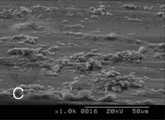
도 2c는 도 2b를 보다 확대하여 텅스텐카바이드와 탄소 코팅층의 단면을 도시한 사진.Figure 2c is a photograph showing a cross-sectional view of the tungsten carbide and carbon coating layer to enlarge the Figure 2b.
도 3a는 티타늄 재질의 임플란트용 스크류의 나사산의 실험후 전자현미경 사진.Figure 3a is an electron micrograph after the experiment of the screw thread of the titanium implant material.
도 3b는 도 3a에 도시된 스크류의 나사산의 표면을 확대한 사진.3B is an enlarged photograph of the surface of the threads of the screw shown in FIG. 3A.
도 4a는 티타늄 재질의 스크류에 텅스텐카바이드와 탄소 코팅층을 형성한 스크류의 나사산의 실험후 전자현미경 사진.Figure 4a is an electron micrograph after the experiment of the screw thread of the tungsten carbide and carbon coating layer formed on the titanium screw.
도 4b는 도 4a에 도시된 스크류의 나사산의 표면을 확대한 사진.4B is an enlarged photograph of the surface of the threads of the screw shown in FIG. 4A.
도 5a는 티타늄 재질의 스크류 표면의 성분에 대한 EDX 분석결과 그래프.Figure 5a is a graph of the EDX analysis of the components of the screw surface of the titanium material.
도 5b는 텅스텐카바이드와 탄소 코팅층을 가진 스크류 표면의 성분에 대한 EDX 분석결과 그래프.5b is a graph of EDX analysis of the components of the screw surface with tungsten carbide and carbon coating layer.
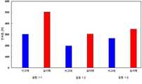
도 6a는 텅스텐카바이트와 탄소 코팅층이 있는 스크류와 없는 스크류의 전하중 측정 결과표.FIG. 6A is a table of results of measurement of charge on screws with and without tungsten carbide and carbon coating layers. FIG.
도 6b는 도 6a를 도식화하여 나타낸 그래프.FIG. 6B is a graph schematically illustrating FIG. 6A. FIG.
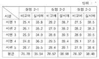
도 7a는 텅스텐카바이트와 탄소 코팅층이 있는 스크류와 없는 스크류의 회전각 측정 결과표.7A is a table of rotation angle measurement results for screws with and without tungsten carbide and carbon coating layers.
도 7b는 도 7a를 도식화하여 나타낸 그래프.FIG. 7B is a graph schematically illustrating FIG. 7A. FIG.
도 8a는 텅스텐카바이트와 탄소 코팅층이 있는 스크류와 없는 스크류의 반복사용에 따른 전하중의 변화량 측정결과표8A is a result table of measurement of changes in charge according to repeated use of a screw with and without a tungsten carbide and carbon coating layer.
도 8b는 도 8a를 도식화하여 나타낸 그래프.FIG. 8B is a graph schematically illustrating FIG. 8A. FIG.
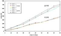
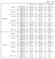
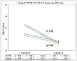
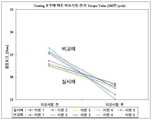
도 9a는 텅스텐카바이트와 탄소 코팅층이 있는 스크류와 없는 스크류 각각에 대하여 조임토크별 전하중의 변화량을 측정 결과표.Figure 9a is a measurement result table of the amount of charge change by tightening torque for each screw with and without tungsten carbide and carbon coating layer.
도 9b는 도 9a를 도식화하여 나타낸 그래프.FIG. 9B is a graph schematically illustrating FIG. 9A. FIG.
도 10은 텅스텐카바이트와 탄소 코팅층이 있는 스크류와 없는 스크류 각각에 대한 피로 시험 전후의 제거토크의 변화량을 측정한 결과표.FIG. 10 is a table showing the result of measuring the amount of change in removal torque before and after the fatigue test for each screw with and without tungsten carbide and carbon coating layers. FIG.
도 11a는 도 10에서 1×10⁵ 사이클 피로시험에 따른 손실토크 및 토크손실율에 관한 표.FIG. 11A is a table showing loss torque and torque loss rate according to the 1 × 10⁵ cycle fatigue test in FIG. 10. FIG.
도 11b는 도 11a의 데이타를 도식화하여 나타낸 그래프.FIG. 11B is a graph depicting the data of FIG. 11A. FIG.
도 12a는 도 10에서 5×10⁵ 사이클 피로시험에 따른 손실토크 및 토크손실율에 관한 표.FIG. 12A is a table showing loss torque and torque loss rate according to 5 × 10⁵ cycle fatigue test in FIG. 10. FIG.
도 12b는 도 12a의 데이타를 도식화하여 나타낸 그래프.FIG. 12B is a graph depicting the data of FIG. 12A. FIG.
도 13a는 도 10에서 1×10⁶사이클 피로시험에 따른 손실토크 및 토크손실율에 관한 표.FIG. 13A is a table showing loss torque and torque loss rate according to the 1 × 10⁶ cycle fatigue test in FIG. 10. FIG.
도 13b는 도 13a의 데이타를 도식화하여 나타낸 그래프.FIG. 13B is a graph depicting the data of FIG. 13A. FIG.
본 발명은 어버트먼트와 픽스츄어간의 체결 등과 같은 임플란트시스템에 사용되는 스크류의 막구조에 관한 것으로, 특히 스크류의 표면상에 텅스텐카바이드와 탄소코팅층을 형성하여 마찰계수를 떨어뜨리고 내마모성을 증대시켜 항상 초기의 체결력을 유지함과 동시에 풀림을 최소화할 수 있는 텅스텐카바이드와 탄소코팅층을 가진 임플란트용 스크류의 막구조에 관한 것이다.The present invention relates to a membrane structure of a screw used in an implant system such as a fastening between an abutment and a fixture, in particular, by forming a tungsten carbide and carbon coating layer on the surface of the screw to reduce the coefficient of friction and increase wear resistance The present invention relates to a membrane structure of an implant screw having a tungsten carbide and carbon coating layer capable of minimizing loosening while maintaining initial clamping force.
임플란트시스템은 환자의 소실된 자연치아를 대신하여 치조골상에 시술되는 대치물로서 크게 치조골상에 매식되는 픽스츄어, 상기 픽스츄어의 상부에 안착되고 보철물이 위치되는 어버트먼트와, 상기 픽스츄어와 어버트먼트를 체결하는데 스크류(1)로 구성된다.The implant system is a substitute to be placed on the alveolar bone in place of the missing natural tooth of the patient, a fixture buried on the alveolar bone, an abutment seated on the upper part of the fixture and the prosthesis is positioned, and the fixture and aur It consists of a screw (1) for fastening the butt.
시술자는 치조골상에 픽스츄어를 매식하고 그 위에 어버트먼트를 위치시킨 다음 스크류를 어버트먼트와 픽스츄어에 삽입하여 나사체결하고, 이어서 어버트먼트상에 환자의 치아와 유사한 보철물을 결합시킴으로서 임플란트 시술을 완료하게 된다.The surgeon implants the fixture on the alveolar bone, places the abutment on it, inserts the screw into the abutment and the fixture, and then screwes on it, then joins the implant similar to the patient's teeth on the abutment. The procedure is completed.
그리고, 임플란트시술이 완료된 뒤에는, 시술된 임플란트시스템은 각종 저작력을 받게 되어 어버트먼트와 픽스츄어를 나사체결하고 있던 스크류가 풀리거나 체결력이 느슨해지게 된다. 따라서, 시술후 이와 같은 상황이 발생하면, 보철물을 파손한 뒤 스크류를 새로 조여 주거나 여의치 아니한 경우에는 기존의 임플란트시스템을 제거하고 재시술을 하기도 한다. 이로 인해, 환자의 고통은 가중되고 시술비용은 높아지는 문제점이 있다. 이와 같은 문제점은 비단 어버트먼트와 픽스츄어를 결합하는 스크류에 국한되는 것은 아니며 기타 치과 임플란트용으로 사용되는 다른 스크류에서도 발생한다. 이런 이유로, 이하에서는 스크류라 함은 임플란트 시술시 사용되는 모든 스크류를 포함하는 것으로 하며, 이를 임플란트용 스크류라 칭한다.Then, after the implant procedure is completed, the implant system is subjected to a variety of chewing power to loosen or loosen the screw was screwing the abutment and fixture. Therefore, if such a situation occurs after the procedure, if the prosthesis is damaged and the screw is newly tightened or if it is not available, the existing implant system may be removed and the procedure may be performed again. As a result, the pain of the patient is aggravated and the procedure cost is high. This problem is not limited to screws that combine silk abutments and fixtures, but also occurs in other screws used for other dental implants. For this reason, hereinafter, the screw is intended to include all the screws used in the implant procedure, which is referred to as an implant screw.
이 처럼 스크류의 풀림과 같은 기계적 결함은, 스크류의 파절을 유발하고, 만약 스크류의 조임에만 관심을 집중하면 골 소실이나 픽스츄어의 파절과 같은 문제점을 유발할 수 있다. 따라서, 성공적인 임플란트 시술을 위해서는 생물학적 그리고 기계적 요소 사이의 적절한 균형이 요구된다.As such, mechanical defects such as loosening of the screw may cause the fracture of the screw, and may cause problems such as bone loss or fracture of the fixture if attention is focused only on the tightening of the screw. Thus, a successful implant procedure requires an appropriate balance between biological and mechanical components.
스크류 풀림을 방지하기 위해서는 스크류의 커넥션부에 가해지는 외부 하중을 최소로 하고, 픽스츄어와 어버트먼트간의 압축력을 최대로 하여야 한다. 외부하중을 최소로 하기 위해서는 올바른 위치에 고정체를 식립하여 보철물 설계시 지레 길이가 최소로 되도록 함과 동시에 픽스츄어 장축을 따라 하중이 전달되도록 교합을 설계함으로서 모멘트에 의한 과도한 응력집중을 피해야 한다. 압축력은 어버트먼트 스크류를 조일 때 가해지는 회전력이 스크류를 신장시켜 발생되는 인장력의 결과이므로 이러한 스크류의 전하중을 최대로 하기 위해서는 허용 한계내에서 나사의 신장을 최대화하여야 한다.In order to prevent screw loosening, the external load applied to the screw connection part should be minimized and the compression force between the fixture and the abutment should be maximized. To minimize external loads, the fixture should be placed in the correct position to minimize the length of the lever in the design of the prosthesis and to design the occlusion so that the load is transmitted along the long axis of the fixture. Since the compressive force is the result of the tensile force generated by tightening the abutment screw as it extends the screw, it is necessary to maximize the extension of the screw within the allowable limits to maximize the charge of the screw.
스크류 체결시 전달되는 회전력 전부가 전하중으로 작용하는 것이 아니라 일부는 마찰력을 극복하기 위하여 소진되는데, 보고되는 바에 따르면, 회전력의 50%는 어버트먼트 스크류의 헤드와 어버트먼트 사이의 접촉면에서 발생하는 마찰력을 극복하기 위하여 소실되고, 40%는 스크류의 나사산과 픽스츄어의 나사산사이의 접촉면에서 발생하는 마찰력을 극복하는데 소실된다. 따라서, 10%의 회전력만이 전하중으로 전환되므로, 체결과정에서의 비가역성은 너무나도 크다고 할 수 있다. 이와 같은 비효율성을 해결하기 위하여, 마찰계수가 작은 스크류를 사용하고자 하는 시도가 이어지고 있다. 일반적으로 스크류의 마찰계수는 금속학적 성질, 기하학적 형태, 표면연마 등에 의해 영향을 받고, 이미 제작된 스크류의 마찰계수는 구강에서 나사 체결시 타액이나 혈액 같은 윤활제의 존재에 의해 감소될 수 있으나 임상적인 효과에 대한 예측은 불가능하다.Not all of the torque transmitted during screwing acts as a charge, but some are exhausted to overcome the frictional force. Reportedly, 50% of the torque is generated at the contact surface between the abutment screw's head and the abutment. It is lost to overcome the friction force, and 40% is lost to overcome the friction force that occurs at the contact surface between the thread of the screw and the thread of the fixture. Therefore, since only 10% of the rotational force is converted into the charge, the irreversibility in the fastening process can be said to be too large. In order to solve such inefficiencies, attempts have been made to use screws having a small coefficient of friction. In general, the coefficient of friction of the screw is affected by metallurgical properties, geometry, surface polishing, etc., and the coefficient of friction of the already manufactured screw can be reduced by the presence of lubricants such as saliva or blood when screwing in the oral cavity, but clinical Prediction of the effect is impossible.
최근 몇몇 임플란트 제조사들이 마찰계수를 줄이기 위하여 건조 윤활제로 스크류를 코팅한 제품을 출시하기도 하였다. 3i(Implant Innovation, 미국)의 순금코팅 스크류인 GoldTite와 Steri-Oss(Novel Biocare, USA)의 테프론 코팅 스크류인 TorqTite가 그 예이다. 하지만, 이와 같은 스크류들은 종래의 티타늄 스크류보다는 전하중이 증가하여 나사 풀림현상이 적다고 보고되고는 있지만, 나사의 반복 체결시 코팅표면의 마모가 나타나 내구성이 떨어지고 마찰계수가 다시 상승되는 문제가 있었다.Recently, some implant manufacturers have introduced products coated with a screw with a dry lubricant to reduce the coefficient of friction. Examples are GoldTite, a pure gold coating screw from Implant Innovation, USA, and TorqTite, a Teflon-coated screw from Steri-Oss (Novel Biocare, USA). However, these screws have been reported to have less screw loosening due to an increase in charge weight than conventional titanium screws. However, the coating surface was worn down repeatedly when the screws were repeatedly tightened, resulting in a decrease in durability and a high coefficient of friction. .
본 발명은 앞서 본 문제점을 해결하기 위하여 안출된 것으로, 본 발명의 목적은, 임플란트용 스크류의 표면상에 텅스텐카바이드를 탄소와 혼합하여 무정형의 초경합금 코팅으로 텅스텐카바이드와 탄소코팅층을 형성하여 표면의 마찰계수를 떨어뜨리고 내마모성을 향상시켜 체결력을 높이고 풀림을 최소한 줄일 수 있는 임플란트용 스크류의 막구조를 제공하는 것이다.The present invention has been made to solve the above problems, an object of the present invention, by mixing tungsten carbide with carbon on the surface of the implant screw to form a tungsten carbide and carbon coating layer of amorphous cemented carbide coating surface friction It is to provide a membrane structure of the implant screw that can increase the tightening force and at least reduce the loosening by reducing the modulus and improved wear resistance.
본 발명은 앞서 본 목적을 달성하기 위하여 다음과 같은 구성을 가진다.The present invention has the following configuration to achieve the above object.
본 발명의 일실시예에 따르면, 본 발명의 스크류의 막구조는, 티타늄 재질의 스크류의 표면에 텅스텐카바이드와 탄소를 플라즈마증착시켜 텅스텐카바이드와 탄소층을 형성함으로서 마찰계수를 떨어뜨리고 내마모성을 향상시키고 체결력을 높이고 풀림을 줄일 수 있는 것을 특징으로 한다.According to an embodiment of the present invention, the film structure of the screw of the present invention, by tungsten carbide and carbon plasma deposition on the surface of the titanium screw to form a tungsten carbide and carbon layer to reduce the friction coefficient and improve the wear resistance It is characterized by increasing the tightening force and reducing loosening.
본 발명의 다른 실시예에 따르면, 본 발명의 스크류의 막구조는, 상기 텅스텐카바이드와 탄소코팅층은, 텅스텐카바이드층과 탄소층이 원자단위로 교차하여 다층구조를 이루는 것을 특징으로 한다.According to another embodiment of the present invention, the screw structure of the screw of the present invention, the tungsten carbide and carbon coating layer, characterized in that the tungsten carbide layer and the carbon layer intersect atomically to form a multi-layer structure.
출원인은 이하에서 앞서 본 실시예들을 각종 실험을 통해 설명하도록 한다.Applicants will be described below through various experiments the present embodiments.
시편의 준비Preparation of the Psalms
스크류는 오스템 임플란트(주)의 티타늄 합금 스크류를 기초하여, 텅스텐카바이드와 탄소코팅층을 형성한 것(이하, '실시예'라 함)와 단순히 오스템 임플란트(주)의 티타늄 합금 스크류(이하, '비교예'라 함)를 수개씩 각각 준비한다.The screw is based on the titanium alloy screw of Osstem Implant Co., Ltd., which forms tungsten carbide and carbon coating layer (hereinafter referred to as 'Example') and simply the titanium alloy screw of Osstem Implant Co., Ltd. Prepare a few pieces each.
여기서, 실시예를 제작하기 위해서 플라즈마증착장치를 사용하는데, 티타늄 합금 스크류를 진공챔버내에 장착하고 10-1 내지 10-2mbar까지 배기시키고 Ar가스를 주입한다. 이어서, 음극 필라멘트가 가열되면서 전자를 방출시키며, 방출된 전자는 양극으로 당겨지고 이 과정에서 주입되는 Ar 가스와 충돌하여 이온과 전자를 발생시켜 방전을 유도하여 플라즈마가 발생한다. 플라즈마를 발생시킨 후 산화층을 포함한 스크류 상의 오염물질 제거를 위하여 10-1 내지 10-2mbar 압력으로 배기시킨다. 그리고, 스크류 상에 잔존할 수 있는 수분을 제거하고 박막의 밀착성을 향상시키기 위하여 250℃이상으로 가열한다. 이어서 표면에 순간적으로 형성되는 극히 미세한 산화막 및 미세 이물질을 제거하기 위하여 에칭공정이 코팅공정에 앞서 진행된다. 이와 같은 에칭공정은 양극성인 Ar 이온이 음극성인 스크류의 표면에 충돌함으로서 대략 0.1㎛의 산화막도 제거하고, 또한 스크류 표면에 잔존할 수 있는 미세한 유기물도 분해하여 코팅 박막의 밀착성을 증진시키게 된다. 이어서 코팅공정이 진행되는데, 상기 코팅공정은 스퍼터링 방식에 의해 진행하였다. 스퍼터링 방식의 코팅 원리를 살펴보면, 텅스텐카바이드 스퍼터링 타겟에 양극성의 Ar 이온이 충돌하여 스퍼트링 타겟에서 텅스텐과 탄소가 혼합된 입자들이 방출되고, 방출된 텅스 텐과 탄소 입자들이 티타늄 합금재질의 스크류 표면에 증착되게 된다. 이때 방출되는 탄소 입자들은 진공펌프에 의해 외부로 배기됨에 의해 상대적으로 증착되는 양이 적어지게 된다. 배기되는 탄소의 양을 보충하기 위해 C2H2 가스를 Ar 가스와 공급하여 주면, 탄소와 수소가 이온화되며 탄소는 스퍼터링 타겟에서 방출되는 텅스텐 입자와 반응하여 텅스텐 카바이드 코팅층을 형성하고 수소 이온들은 진공 펌프에 의해 외부로 방출되게 된다.Here, a plasma deposition apparatus is used to fabricate an embodiment, in which a titanium alloy screw is mounted in a vacuum chamber, exhausted to 10−1 to 10−2 mbar, and injected with Ar gas. Subsequently, the cathode filament is heated to emit electrons, and the emitted electrons are attracted to the anode and collide with the Ar gas injected in the process to generate ions and electrons to induce discharge to generate plasma. The plasma is generated and then evacuated to a pressure of 10−1 to 10−2 mbar to remove contaminants on the screw including the oxide layer. And, to remove the moisture remaining on the screw and heated to 250 ℃ or more to improve the adhesion of the thin film. Subsequently, an etching process is performed prior to the coating process in order to remove extremely fine oxide film and fine foreign matter which are instantaneously formed on the surface. Such an etching process removes an oxide film having a thickness of approximately 0.1 μm by colliding with the surface of the negative electrode of the positive ion, and also decomposes the fine organic substances remaining on the surface of the screw, thereby improving the adhesion of the coating thin film. Subsequently, a coating process is performed, and the coating process is performed by a sputtering method. In the sputtering coating principle, bipolar Ar ions collide with the tungsten carbide sputtering target to release the tungsten and carbon mixed particles from the sputtering target, and the released tungsten and carbon particles are formed on the titanium alloy screw surface. To be deposited. At this time, the carbon particles emitted are exhausted to the outside by the vacuum pump, so that the amount of deposition is relatively small. When C2 H2 gas is supplied with Ar gas to replenish the amount of carbon released, carbon and hydrogen are ionized, and carbon reacts with tungsten particles emitted from the sputtering target to form a tungsten carbide coating layer and hydrogen ions are vacuumed. It is discharged to the outside by the pump.
이와 같은 공정을 거쳐 제작된 텅스텐카바이드와 탄소층의 두께는 대략 1.5~3.5㎛이고, 도 2c에 도시된 바와 같다.The thickness of the tungsten carbide and the carbon layer produced through such a process is approximately 1.5 ~ 3.5㎛, as shown in Figure 2c.
후술하는 바와 같이, 위와 같은 공정을 거쳐 제조된 실시예는 4종류의 실험에 사용되므로 실험1용으로 15개, 실험2용으로 15개, 실험3용으로 6개, 실험4용으로 5개를 준비한다. 마찬가지로, 실시예와 비교가능하도록 비교예도 각각 동일한 개수만큼 준비한다.As described below, the examples prepared through the above process are used for four kinds of experiments, so 15 for
한편,Meanwhile,픽스츄어와Fixtures and어버트먼트는Abutment 출원인이 생산판매하고 있는 Produced and sold by the applicantGSGS타입, US타입, SS타입으로 준비한다.It is available in type, US type, SS type.
실험1 : 텅스텐카바이드와 탄소코팅층의 유무에 따른 전하중Experiment 1: Charge Charge with or without Tungsten Carbide and Carbon Coating Layer
목적: purpose:
텅스텐카바이드와 탄소코팅층의 유무가 스크류조임에 따른 스크류에 발생되는 인장력에 의해 픽스츄어와 어버트먼트간에 발생되는 압축력(전하중)에 미치는 영향을 검토하고자 한다. The effect of the presence or absence of tungsten carbide and carbon coating layer on the compressive force (charge load) generated between the fixture and the abutment by the tension force generated in the screw due to the screw tightening.
실험장비 및 방법: Experimental Equipment and Methods:
압전소자방식으로 된 SlimLine Force Sensor(9132B21, KISTLER, 스위스)를 이용한 압축력 측정장치를 고안하였다. 압축력 측정을 위하여 센서와 임플란트부품들을 차례로 연결한 후, 디지털토크게이지를 이용하여 비교예와 실시예의 어버트먼트 스크류를 30Ncm까지 천천히 조이고, 디지털표시기(MI-15W, SENSTECH, 한국)에 나타난 압축력을 측정하였다. US, SS, GS 타입 픽스츄어와 어버트먼트에 대하여 각각 5개 시편의 실시예와 비교예를 실험하였으며, US타입에 대하여 실험 1-1, SS타입에 대하여 실험 1-2, GS타입에 대하여 실험 1-3으로 명명하였다. Compression force measuring device using piezoelectric slimline force sensor (9132B21, KISTLER, Switzerland) was devised. In order to measure the compressive force, connect the sensor and the implant parts one by one, and then slowly tighten the abutment screw of Comparative Example and Example to 30 Ncm using the digital torque gauge, and measure the compressive force displayed on the digital display (MI-15W, SENSTECH, Korea). Measured. Examples and comparative examples of five specimens were tested for US, SS, and GS type fixtures and abutments, respectively. Experiment 1-1 for US type, Experiment 1-2 for SS type, and GS type for GS type. It was named Experiment 1-3.
실험결과:Experiment result:
도 6a와 도 6b에 실험 1의 결과가 각각 표와 그래프로서 도시되어 있다.The results of
도 6a와 6b에 도시된 바에 의하면, 시편 1 내지 5에 대하여 텅스텐카바이드와 탄소층을 가진 실시예가 비교예에 비해 84N~200N 정도 높음을 알 수 있었다. 또한, 동일한 실시예라 하더라도, 압축력은 US타입>GS타입>SS타입 순으로 나타났다. 이와 같은 결과는, 텅스텐카바이드와 탄소층을 가진 실시예가 티타늄 재질의 비교예보다 월등히 높은 전하중을 얻을 수 있어서 체결력이나 풀림방지 효과측면에서 실시예가 비교예보다 우수하다는 사실을 확인시켜 준다.6A and 6B, it can be seen that the examples having tungsten carbide and carbon layers for
실험2:텅스텐카바이드와 탄소코팅층의 유무에 따른 스크류의 회전각Experiment 2: Screw Rotation Angle with or without Tungsten Carbide and Carbon Coating Layer
목적:purpose:
어버트먼트와 픽스츄어를 결합함에 있어서 스크류의 회전범위는 어버트먼트와 픽스츄어간의 체결력을 가늠하는 요소이자 스크류의 마찰계수의 높낮음을 판단할 수 있는 요소이므로, 출원인은 실시예와 비교예 각각에 대하여 US, SS, GS타입에 대하여 조임시 최대 회전가능한 각도를 측정하여 텅스텐카바이드와 탄소코팅층이 마찰계수에 미치는 영향을 분석하고자 한다.In the combination of the abutment and the fixture, the rotation range of the screw is a factor for determining the fastening force between the abutment and the fixture and a factor for determining the high friction coefficient of the screw. This study is to analyze the effect of tungsten carbide and carbon coating layer on the friction coefficient by measuring the maximum rotatable angle during tightening for US, SS and GS types.
실험장비 및 방법:Experimental Equipment and Methods:
실험장치에 픽스츄어를 위치시키고, 디지털토크게이지(DTDX-20EX, KANON, 일본)을 이용하여 5Ncm로 스크류를 조인 후 회전각 측정을 위한 디지털 측정기(CT6Y-1, Autonics, 한국)의 영점 조정을 하였다. 그 후, 디지털 토크게이지로 계속적인 조임 회전력을 가하여 30Ncm까지 스크류를 천천히 회전시키고 그 때의 조임 회전각을 측정하였다. US, SS, GS 타입 픽스츄어와 어버트먼트에 대하여 각각 5개 시편의 실시예와 비교예를 실험하였으며, US타입에 대하여 실험 2-1, SS타입에 대하여 실험 2-2, GS타입에 대하여 실험 2-3으로 명명하였다.Place the fixture on the experimental device, tighten the screw to 5 Ncm using the digital torque gauge (DTDX-20EX, KANON, Japan), and then adjust the zero point of the digital measuring instrument (CT6Y-1, Autonics, Korea) to measure the rotation angle. It was. Thereafter, by applying a continuous tightening torque with a digital torque gauge, the screw was slowly rotated to 30 Ncm, and the tightening rotation angle at that time was measured. Examples and comparative examples of five specimens were tested for US, SS, and GS type fixtures and abutments, respectively. Experiment 2-1 for US type, Experiment 2-2 for SS type, and GS type. It was named Experiment 2-3.
실험결과:Experiment result:
도 7a와 도 7b에 실험 2의 결과가 각각 표와 그래프로서 도시되어 있다.The results of
도 7a와 7b에 도시된 바에 의하면, 시편 1 내지 5에 대하여 텅스텐카바이드와 탄소층을 가진 실시예가 비교예에 비해 회전각이 10ㅀ정도 높음을 알 수 있었다. 또한, 동일한 실시예라 하더라도, 회전각은 SS타입>GS타입>US타입 순으로 나타났다. 이와 같은 결과는 동일한 토오크를 가했을 때, 실시예의 스크류가 비교예의 것에 비해 많이 회전하였다는 것을 의미하고 이는 곧 텅스텐카바이드와 탄소층을 가진 실시예가 티타늄 재질의 비교예보다 마찰계수가 작다는 사실과 보다 높은 체결력과 풀림방지 효과를 가진다는 사실을 보여주는 것이다.As shown in FIGS. 7A and 7B, the examples having the tungsten carbide and the carbon layer with respect to
실험3: 스크류의 반복사용에 따른 전하중의 변화량, 막표면의 마모여부, 표면 성분분석Experiment 3 : Change in Charge, Repeated Wear of Membrane Surface, and Surface Composition by Repeated Use of Screw
목적:purpose:
실시예와 비교예를 여러번에 걸쳐 조였다 풀었다 하는 과정을 반복하면서 전하중을 측정함으로서 텅스텐카바이드와 탄소코팅층이 반복사용에 미치는 영향을 평가하고자 한다.The effect of tungsten carbide and carbon coating layer on repeated use is evaluated by measuring the charge weight while repeating the process of tightening and releasing the example and the comparative example several times.
실험장비 및 실험방법:Experiment equipment and method:
압축력 측정장치에 GS타입의 픽스츄어와 어버트먼트를 고정하고 30Ncm의 회 전력으로 실시예와 비교예의 스크류를 천천히 조여 압축력(전하중)을 측정한 뒤 다시 푸는 과정을 10회 반복측정하였다. 실시예와 비교예는 각각 3개의 시편을 사용하였다. 이와같은 실험을 실험 3-1이라 한다.The GS type fixture and abutment were fixed to the compression force measuring device, and the screw of the examples and the comparative example was slowly tightened with a rotational force of 30 Ncm to measure the compressive force (charge load), and then the loosening process was repeated 10 times. In the Examples and Comparative Examples, three specimens were used. This experiment is called Experiment 3-1.
또한, 조임토크를 5Ncm에서 50Ncm까지 5Ncm씩 증가시켜가면서 10번에 걸쳐 전하중을 측정하였는데, 실시예와 비교예 각각 3개씩의 시편에 대하여 실험을 하였으며,이를 실험 3-2라 한다.In addition, the charge torque was measured 10 times while increasing the tightening torque from 5Ncm to 50Ncm by 5Ncm. Experiments were carried out on three specimens of each of Examples and Comparative Examples, which is referred to as Experiment 3-2.
마지막으로, 실시예와 비교예의 표면의 성분을 EDX(Energy Dispersive X-ray(EDX))로 분석하였다.Finally, the components of the surface of the Examples and Comparative Examples were analyzed by Energy Dispersive X-ray (EDX).
실험결과:Experiment result:
도 8a와 도 8b에 실험 3-1의 결과가 각각 표와 그래프로서 도시되어 있다.The results of Experiment 3-1 are shown in tables and graphs in FIGS. 8A and 8B, respectively.
도 8a와 8b에 도시된 바에 의하면, 실시예의 경우, 3개의 시편 모두에 대하여 10번에 걸친 측정된 전하중은 348~390N으로서 반복적인 사용에도 불구하고 측정된 전하중에는 별다른 변화가 없었다. 반면, 비교예의 경우, 반복체결을 하면 일정구간에서는 전하중이 증가하다가 점차적으로 감소한 후 일정해지는 경향을 보였다. 또한, 전하중의 크기를 비교해 보면, 실시예가 비교예에 비해 평균 30.2% 높게 측정되었다.As shown in FIGS. 8A and 8B, in the case of the examples, the measured charges over 10 times for all three specimens were 348-390N, and there was no change in the measured charges despite repeated use. On the other hand, in the comparative example, when repeated fastening, the charge weight increased in a certain period, and then gradually decreased and then became constant. In addition, when comparing the magnitude | size of an electric charge, the Example measured 30.2% higher than the comparative example.
위 결과로 볼 때, 실시예가 비교예에 비해 전하중이 높고 반복사용에도 불구하고 변하지 않는 내구성을 가지고 있음을 알 수 있다.From the above results, it can be seen that the embodiment has a higher charge weight than the comparative example and has a durability that does not change despite repeated use.
이와 같은 사실은 도 1a 내지 도 3b의 SEM 사진에서도 확인할 수 있다.도 1a 는 비교예의 나사산의 실험전 SEM 사진이고(100배 확대), 도 1b는 도 1a에 도시된 스크류의 나사산의 표면을 확대한 사진이다(1000배 확대). 그리고, 도 2a는 실시예의 나사산의 실험전 SEM사진이고(100배 확대), 도 2b는 도 2a에 도시된 스크류의 나사산의 표면을 확대한 사진이다(1000배 확대). 도 2c는 도 2b를 보다 확대하여 텅스텐카바이드와 탄소 코팅층의 단면을 촬영한 사진이다(10000배 확대).This fact can also be confirmed in the SEM photographs of FIGS. 1A to 3B. FIG. 1A is a pre-experimental SEM photograph of the threads of the comparative example (100 times magnification), and FIG. 1B is an enlarged surface of the threads of the screw shown in FIG. 1A. One picture (1000x magnification). 2A is a pre-experimental SEM photograph of the thread of the embodiment (100 times magnification), and FIG. 2B is an enlarged photograph of the surface of the thread of the screw shown in FIG. 2A (1000 times magnification). FIG. 2C is a photograph of a cross section of the tungsten carbide and the carbon coating layer by enlarging FIG. 2B (10000 times magnification).
도 1a 내지 도 2b를 참조하면, 실시예와 비교예의 막 단면은 유사해 보이지만, 도 2c를 보면 실시예와 비교예의 막 구조가 상이함을 알 수 있다. 도 2c에 도시된 바에 의하면, 실시예의 막구조는 횡방향으로 수백층이 상호 교차하며 다층 구조를 이루고 있고 종방향으로는 마치 고드름 처럼 성장하되 상측으로 갈수록 그 형상이나 치수가 다른 다층 구조를 이루고 있다.1A to 2B, the cross sections of the examples and the comparative example may look similar, but FIG. 2C shows that the membrane structures of the examples and the comparative example are different. As shown in FIG. 2C, the membrane structure of the embodiment has a multi-layer structure in which several hundred layers cross each other in a transverse direction and grow like icicles in a longitudinal direction, but have a multi-layer structure having different shapes or dimensions toward the upper side. .
도 3a는 비교예의 나사산의 실험후 SEM 사진(100배 확대)이고, 도 3b는 도 3a에 도시된 스크류의 나사산의 표면을 확대한 사진(1000배 확대)이다. 도 4a는 실시예의 나사산의 실험후 SEM 사진이고(100배 확대),도 4b는 도 4a에 도시된 스크류의 나사산의 표면을 확대한 사진(1000배 확대)이다.FIG. 3A is an SEM image (100 times magnification) after the experiment of the threads of the comparative example, and FIG. 3B is an enlarged photograph (1000 times magnification) of the surface of the threads of the screw shown in FIG. 3A. 4A is an SEM image after the experiment of the thread of the embodiment (100 times magnification), and FIG. 4B is an enlarged photograph (1000 times magnification) of the surface of the thread of the screw shown in FIG. 4A.
비교예의 경우, 도 3b의 막표면은 도 1b의 막표면과는 달리 심하게 마모되었음을 확인할 수 있다. 반면, 실시예의 경우, 도 4b의 막표면이나 도 2b의 막표면이나 별다른 변화가 없음을 확인할 수 있다. 이는, 곧 10회 반복 체결시 비교예의 막표면에는 마모가 발생되는 반면 실시예의 막표면에는 별다른 변화가 없다는 것을 의미한다. 결국, 텅스텐카바이드와 탄소코팅층을 형성함으로 반복적인 체결에도 불구하고 마모를 방지할 수 있음을 확인할 수 있다.In the case of the comparative example, it can be seen that the film surface of Figure 3b is badly worn unlike the film surface of Figure 1b. On the other hand, in the case of the embodiment, it can be seen that there is no change in the film surface of Figure 4b or the film surface of Figure 2b. This means that abrasion occurs on the film surface of the comparative example after ten repeated fastenings, but there is no change in the film surface of the example. As a result, it can be seen that the formation of tungsten carbide and carbon coating layer can prevent abrasion despite repeated fastening.
또한, EDX관찰 결과를 살펴보면, 도 5a에 도시된 텅스텐카바이드와 탄소층을 가지지 않은 비교예의 경우에는, 표면에는 주성분으로 티타늄과 알루미늄 그리고 바나듐이 주로 검출된 반면, 도 5b에 도시된 실시예의 경우에는, 표면에는 주성분으로 텅스텐과 카바이드가 주로 검출되었다. 따라서, 실시예의 표면에는 텅스텐카바이드와 탄소층이 형성되어 있음을 확인할 수 있다.In addition, looking at the EDX observation results, in the case of the comparative example without the tungsten carbide and carbon layer shown in Figure 5a, mainly titanium, aluminum and vanadium are mainly detected on the surface, while in the case of the embodiment shown in Figure 5b On the surface, tungsten and carbide were mainly detected. Therefore, it can be seen that tungsten carbide and a carbon layer are formed on the surface of the embodiment.
실험4:피로하중에 대한 손실토크와 토크손실율 측정Experiment 4 : Measurement of Lost Torque and Torque Loss Ratio for Fatigue Load
목적:purpose:
실시예와 비교예에 반복적인 피로하중을 가하기 전후의 풀림토크(체결된 스크류를 제거하는데 필요한 토크)를 각각 측정하여 텅스텐카바이드와 탄소코팅층이 피로하중에 의한 풀림에 미치는 영향을 평가하고자 한다.The loosening torque (torque required to remove the fastened screw) before and after applying repeated fatigue loads to the Examples and Comparative Examples was measured to evaluate the effect of tungsten carbide and carbon coating layer on the loosening due to fatigue load.
실험장비와 실험방법:Experimental Equipment and Methods:
US타입의 픽스츄어와 어버트먼트에 실시예와 비교예를 각각 30Ncm 크기로 체결하고 피로측정기(INSTRON 8841, INSTRON, 미국)에 걸어서, 250N의 하중을 수직에서 30ㅀ 경사진 방향에서 주파수 2Hz 주기로 1×10⁵(실험 4-1), 5×10⁵(실험 4-2), 1×10⁶(실험 4-3) 횟수 가한다. 물론, 피로하중을 가하기 전의 풀림토크를 측정하고 피로하중을 가한 후의 풀림토크를 측정한다. 각각의 실험에 대하여 5개의 시편에 대하여 실험을 반복하였다.Fasten the 250N load at a frequency of 2Hz in a direction inclined at 30Hz from the vertical by fastening the embodiment and the comparative example to the US type fixture and abutment with a size of 30 Ncm respectively and hanging on a fatigue measuring instrument (INSTRON 8841, INSTRON, USA). Add 1 × 10⁵ (Exp. 4-1), 5 × 10⁵ (Exp. 4-2), 1 × 10⁶ (Exp. 4-3). Of course, the loosening torque before the fatigue load is measured and the loosening torque after the fatigue load is measured. The experiment was repeated for five specimens for each experiment.
실험결과:Experiment result:
도 10은 텅스텐카바이트와 탄소 코팅층이 있는 스크류와 없는 스크류 각각에 대한 피로 시험 전후의 제거토크의 변화량을 측정한 결과표이이다.10 is a table showing the result of measuring the amount of change in the removal torque before and after the fatigue test for each screw with and without tungsten carbide and carbon coating layer.
도 11a는 도 10에서 1×10⁵ 사이클 피로시험에 따른 손실토크 및 토크손실율에 관한 표이고, 도 11b는 도 11a의 데이타를 도식화하여 나타낸 그래프이다.FIG. 11A is a table showing loss torque and torque loss rate according to the 1 × 10⁵ cycle fatigue test in FIG. 10, and FIG. 11B is a graph showing the data of FIG. 11A.
도 11a 내지 도 11b를 참조하면, 1×10⁵ 사이클 피로시험인 실험 4-1의 경우에, 손실 토크나 토크손실율에 있어서 실시예가 비교예보다 적다는 것을 알 수 있다. 실험 4-2의 결과인 도 12a 내지 도 12b 그리고 실험 4-3인 도 13a 내지 도 13b에서도 동일한 결론을 확인할 수 있었다. 따라서, 티타늄막만을 가진 비교예에 비해 텅스텐카바이드와 탄소코팅막을 추가로 가지는 실시예가 피로하중에 대하여 보다 안정적이다고 볼 수 있다.11A to 11B, in the case of Experiment 4-1, which is a 1 × 10⁵ cycle fatigue test, it can be seen that the Examples are less than the Comparative Examples in the loss torque and the torque loss ratio. The same conclusion can be confirmed in FIGS. 12A to 12B, which are the results of Experiment 4-2, and FIGS. 13A to 13B, which are Experiment 4-3. Therefore, it can be seen that the embodiment further having tungsten carbide and carbon coating film is more stable against fatigue load than the comparative example having only titanium film.
앞서 본 각종 실험결과에서 확인되다시피, 티타늄막상에 텅스텐카바이드와 탄소코팅막을 형성함으로서 내구성이 증대되고 마찰계수가 낮아져, 높은 체결력 뿐만 아니라 풀림방지 측면에서 우수한 결과를 얻을 수 있다.As can be seen from the various experimental results, the formation of tungsten carbide and carbon coating on the titanium film increases durability and lowers the coefficient of friction, thereby achieving excellent results in terms of high clamping force and anti-loosening.
본 발명은 앞서 본 구성에 의하여 다음과 같은 효과를 가진다.The present invention has the following effects by the above configuration.
본 발명은 임플란트용 스크류의 표면상에 텅스텐카바이드를 탄소와 혼합하여 무정형의 초경합금 코팅으로 텅스텐카바이드와 탄소코팅층을 형성하여 표면의 마찰계수를 떨어뜨리고 내마모성을 향상시켜 체결력을 높이고 풀림을 최소한 줄일 수 있다는 효과를 가진다.The present invention is to form a tungsten carbide and carbon coating layer of amorphous cemented carbide coating by mixing tungsten carbide with carbon on the surface of the implant screw to reduce the friction coefficient of the surface and improve the wear resistance to increase the tightening force and at least reduce the loosening Has an effect.
Claims (2)
Translated fromKoreanPriority Applications (1)
| Application Number | Priority Date | Filing Date | Title |
|---|---|---|---|
| KR1020060126652AKR100765920B1 (en) | 2006-12-12 | 2006-12-12 | Membrane structure of screw for implant with tungsten carbide and carbon coating layer |
Applications Claiming Priority (1)
| Application Number | Priority Date | Filing Date | Title |
|---|---|---|---|
| KR1020060126652AKR100765920B1 (en) | 2006-12-12 | 2006-12-12 | Membrane structure of screw for implant with tungsten carbide and carbon coating layer |
Publications (1)
| Publication Number | Publication Date |
|---|---|
| KR100765920B1true KR100765920B1 (en) | 2007-10-10 |
Family
ID=39419960
Family Applications (1)
| Application Number | Title | Priority Date | Filing Date |
|---|---|---|---|
| KR1020060126652AActiveKR100765920B1 (en) | 2006-12-12 | 2006-12-12 | Membrane structure of screw for implant with tungsten carbide and carbon coating layer |
Country Status (1)
| Country | Link |
|---|---|
| KR (1) | KR100765920B1 (en) |
Cited By (2)
| Publication number | Priority date | Publication date | Assignee | Title |
|---|---|---|---|---|
| KR102427732B1 (en)* | 2022-01-25 | 2022-08-01 | 한국진공주식회사 | Wc/c coating film structure for extending lifetime of press roll for producing facility of secondary battery |
| KR102629684B1 (en)* | 2023-02-13 | 2024-01-25 | 강정환 | The WCC vacuum deposition method of dental implant screw |
Citations (6)
| Publication number | Priority date | Publication date | Assignee | Title |
|---|---|---|---|---|
| US5725573A (en) | 1994-03-29 | 1998-03-10 | Southwest Research Institute | Medical implants made of metal alloys bearing cohesive diamond like carbon coatings |
| KR20000016704A (en)* | 1997-04-17 | 2000-03-25 | 키이스 디 | Dental implant system having improved stability |
| JP2002143185A (en) | 2000-11-13 | 2002-05-21 | Utec:Kk | Dental implant and method of manufacturing the same |
| KR20020094839A (en)* | 2001-06-13 | 2002-12-18 | 곽재영 | DLC-coated dental titanium implant and the method of processing thereof |
| KR20050089916A (en)* | 2004-03-06 | 2005-09-09 | 정재헌 | Method for manufacturing of surface coating on the screw release of dental implant screw |
| KR20050096721A (en)* | 2004-03-31 | 2005-10-06 | 한국과학기술연구원 | Medical composite material and method for manufacturing therefor |
- 2006
- 2006-12-12KRKR1020060126652Apatent/KR100765920B1/enactiveActive
Patent Citations (6)
| Publication number | Priority date | Publication date | Assignee | Title |
|---|---|---|---|---|
| US5725573A (en) | 1994-03-29 | 1998-03-10 | Southwest Research Institute | Medical implants made of metal alloys bearing cohesive diamond like carbon coatings |
| KR20000016704A (en)* | 1997-04-17 | 2000-03-25 | 키이스 디 | Dental implant system having improved stability |
| JP2002143185A (en) | 2000-11-13 | 2002-05-21 | Utec:Kk | Dental implant and method of manufacturing the same |
| KR20020094839A (en)* | 2001-06-13 | 2002-12-18 | 곽재영 | DLC-coated dental titanium implant and the method of processing thereof |
| KR20050089916A (en)* | 2004-03-06 | 2005-09-09 | 정재헌 | Method for manufacturing of surface coating on the screw release of dental implant screw |
| KR20050096721A (en)* | 2004-03-31 | 2005-10-06 | 한국과학기술연구원 | Medical composite material and method for manufacturing therefor |
Cited By (2)
| Publication number | Priority date | Publication date | Assignee | Title |
|---|---|---|---|---|
| KR102427732B1 (en)* | 2022-01-25 | 2022-08-01 | 한국진공주식회사 | Wc/c coating film structure for extending lifetime of press roll for producing facility of secondary battery |
| KR102629684B1 (en)* | 2023-02-13 | 2024-01-25 | 강정환 | The WCC vacuum deposition method of dental implant screw |
Similar Documents
| Publication | Publication Date | Title |
|---|---|---|
| Kim et al. | The biocompatibility of SLA-treated titanium implants | |
| Wennerberg et al. | On implant surfaces: a review of current knowledge and opinions. | |
| Park et al. | The effects of ion beam-assisted deposition of hydroxyapatite on the grit-blasted surface of endosseous implants in rabbit tibiae. | |
| EP1534167B9 (en) | An implant and a method for treating an implant surface | |
| Park et al. | Osteoconductivity of hydrophilic microstructured titanium implants with phosphate ion chemistry | |
| Lee et al. | Biological performance of calcium phosphate films formed on commercially pure Ti by electron-beam evaporation | |
| Yeo et al. | Biomechanical and histomorphometric study of dental implants with different surface characteristics | |
| Sun et al. | Effect of surface modification on the long-term stability of dental implant abutment screws by plasma nitriding treatment | |
| KR101630195B1 (en) | Blasting metallic implants with titanium oxide | |
| Shibli et al. | Analysis of failed commercially pure titanium dental implants: A scanning electron microscopy and energy‐dispersive spectrometer x‐ray study | |
| RU2571559C1 (en) | Method for making endosseous carbon-coated dental implant | |
| Sawase et al. | Application of oxygen ion implantation to titanium surfaces: effects on surface characteristics, corrosion resistance, and bone response | |
| El-Helbawy et al. | Comparison of Oxygen Plasma Treatment and Sandblasting of Titanium Implant-Abutment Surface on Bond Strength and Surface Topography. | |
| Kim et al. | Bone cutting capacity and osseointegration of surface-treated orthodontic mini-implants | |
| KR100765920B1 (en) | Membrane structure of screw for implant with tungsten carbide and carbon coating layer | |
| Zhou et al. | Coating of sandblasted and acid-etched dental implants with tantalum using vacuum plasma spraying | |
| Song et al. | Osseointegration of magnesium-incorporated sand-blasted acid-etched implant in the dog mandible: resonance frequency measurements and histomorphometric analysis | |
| US9138507B2 (en) | Method for manufacturing an implant material | |
| Mackey et al. | Development of niobium oxide coatings on sand-blasted titanium alloy dental implants | |
| Kakura et al. | Zirconia implant with rough surface produced by YAG laser treatment: Evaluation of histomorphology and strength of osseointegration | |
| Peck et al. | Chemical and topographic analysis of eight commercially available dental implants | |
| JP5327934B2 (en) | Implant material and manufacturing method thereof | |
| Lee et al. | Influence of shoulder coverage difference of abutment on stress distribution and screw stability in tissue-level internal connection implants: A finite element analysis and in vitro study | |
| KR100540345B1 (en) | Manufacturing method of abutment screw with improved loosening prevention function for dental implants | |
| KR100426322B1 (en) | DLC-coated dental titanium implant and the method of processing thereof |
Legal Events
| Date | Code | Title | Description |
|---|---|---|---|
| A201 | Request for examination | ||
| PA0109 | Patent application | Patent event code:PA01091R01D Comment text:Patent Application Patent event date:20061212 | |
| PA0201 | Request for examination | ||
| E701 | Decision to grant or registration of patent right | ||
| PE0701 | Decision of registration | Patent event code:PE07011S01D Comment text:Decision to Grant Registration Patent event date:20070921 | |
| GRNT | Written decision to grant | ||
| PR0701 | Registration of establishment | Comment text:Registration of Establishment Patent event date:20071004 Patent event code:PR07011E01D | |
| PR1002 | Payment of registration fee | Payment date:20071005 End annual number:3 Start annual number:1 | |
| PG1601 | Publication of registration | ||
| PR1001 | Payment of annual fee | Payment date:20090902 Start annual number:4 End annual number:4 | |
| PR1001 | Payment of annual fee | Payment date:20110921 Start annual number:5 End annual number:5 | |
| FPAY | Annual fee payment | Payment date:20120904 Year of fee payment:6 | |
| PR1001 | Payment of annual fee | Payment date:20120904 Start annual number:6 End annual number:6 | |
| FPAY | Annual fee payment | Payment date:20131001 Year of fee payment:7 | |
| PR1001 | Payment of annual fee | Payment date:20131001 Start annual number:7 End annual number:7 | |
| FPAY | Annual fee payment | Payment date:20140922 Year of fee payment:8 | |
| PR1001 | Payment of annual fee | Payment date:20140922 Start annual number:8 End annual number:8 | |
| FPAY | Annual fee payment | Payment date:20150820 Year of fee payment:9 | |
| PR1001 | Payment of annual fee | Payment date:20150820 Start annual number:9 End annual number:9 | |
| FPAY | Annual fee payment | Payment date:20170822 Year of fee payment:11 | |
| PR1001 | Payment of annual fee | Payment date:20170822 Start annual number:11 End annual number:11 | |
| FPAY | Annual fee payment | Payment date:20181001 Year of fee payment:12 | |
| PR1001 | Payment of annual fee | Payment date:20181001 Start annual number:12 End annual number:12 | |
| FPAY | Annual fee payment | Payment date:20190402 Year of fee payment:13 | |
| PR1001 | Payment of annual fee | Payment date:20190402 Start annual number:13 End annual number:13 | |
| PR1001 | Payment of annual fee | Payment date:20200925 Start annual number:14 End annual number:14 | |
| PR1001 | Payment of annual fee | Payment date:20210927 Start annual number:15 End annual number:15 | |
| PR1001 | Payment of annual fee | Payment date:20240925 Start annual number:18 End annual number:18 |