KR100765762B1 - Hybrid Image Forming Device - Google Patents
Hybrid Image Forming DeviceDownload PDFInfo
- Publication number
- KR100765762B1 KR100765762B1KR1020050097267AKR20050097267AKR100765762B1KR 100765762 B1KR100765762 B1KR 100765762B1KR 1020050097267 AKR1020050097267 AKR 1020050097267AKR 20050097267 AKR20050097267 AKR 20050097267AKR 100765762 B1KR100765762 B1KR 100765762B1
- Authority
- KR
- South Korea
- Prior art keywords
- unit
- print head
- carriage
- printing
- image forming
- Prior art date
- Legal status (The legal status is an assumption and is not a legal conclusion. Google has not performed a legal analysis and makes no representation as to the accuracy of the status listed.)
- Expired - Fee Related
Links
Images


Classifications
- B—PERFORMING OPERATIONS; TRANSPORTING
- B41—PRINTING; LINING MACHINES; TYPEWRITERS; STAMPS
- B41J—TYPEWRITERS; SELECTIVE PRINTING MECHANISMS, i.e. MECHANISMS PRINTING OTHERWISE THAN FROM A FORME; CORRECTION OF TYPOGRAPHICAL ERRORS
- B41J3/00—Typewriters or selective printing or marking mechanisms characterised by the purpose for which they are constructed
- B41J3/54—Typewriters or selective printing or marking mechanisms characterised by the purpose for which they are constructed with two or more sets of type or printing elements
- B41J3/543—Typewriters or selective printing or marking mechanisms characterised by the purpose for which they are constructed with two or more sets of type or printing elements with multiple inkjet print heads
- B—PERFORMING OPERATIONS; TRANSPORTING
- B41—PRINTING; LINING MACHINES; TYPEWRITERS; STAMPS
- B41J—TYPEWRITERS; SELECTIVE PRINTING MECHANISMS, i.e. MECHANISMS PRINTING OTHERWISE THAN FROM A FORME; CORRECTION OF TYPOGRAPHICAL ERRORS
- B41J29/00—Details of, or accessories for, typewriters or selective printing mechanisms not otherwise provided for
- B41J29/38—Drives, motors, controls or automatic cut-off devices for the entire printing mechanism
- B41J29/393—Devices for controlling or analysing the entire machine ; Controlling or analysing mechanical parameters involving printing of test patterns
- G—PHYSICS
- G06—COMPUTING OR CALCULATING; COUNTING
- G06F—ELECTRIC DIGITAL DATA PROCESSING
- G06F3/00—Input arrangements for transferring data to be processed into a form capable of being handled by the computer; Output arrangements for transferring data from processing unit to output unit, e.g. interface arrangements
- G06F3/12—Digital output to print unit, e.g. line printer, chain printer
Landscapes
- Engineering & Computer Science (AREA)
- Theoretical Computer Science (AREA)
- Human Computer Interaction (AREA)
- Physics & Mathematics (AREA)
- General Engineering & Computer Science (AREA)
- General Physics & Mathematics (AREA)
- Accessory Devices And Overall Control Thereof (AREA)
- Common Mechanisms (AREA)
Abstract
Translated fromKoreanDescription
Translated fromKorean도 1은 본 발명에 따른 하이브리드 화상형성장치의 일 실시예를 개략적으로 보여주는 도면이다.1 is a view schematically showing an embodiment of a hybrid image forming apparatus according to the present invention.
도 2는 본 발명에 따른 하이브리드 화상형성장치의 구성을 설명하기 위한 도면이다.2 is a view for explaining the configuration of the hybrid image forming apparatus according to the present invention.
도 3은 도 2에 도시된 하이브리드 화상형성장치 중 제1프린트 헤드 유니트를 도시한 사시도이다.3 is a perspective view illustrating a first print head unit of the hybrid image forming apparatus illustrated in FIG. 2.
도 4는 도 3의 제1프린트 헤드 유니트가 장착부에 장착된 모습을 도시한 측단면도이다.4 is a side cross-sectional view illustrating a state in which the first print head unit of FIG. 3 is mounted on the mounting unit.
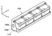
도 5는 도 2에 도시된 하이브리드 화상형성장치 중 제2프린트 헤드 유니트를 도시한 사시도이다.FIG. 5 is a perspective view illustrating a second print head unit of the hybrid image forming apparatus illustrated in FIG. 2.
도 6은 본 발명에 따른 전자사진방식 화상형성유니트의 일 실시예를 보여주는 도면이다.6 is a view showing an embodiment of an electrophotographic image forming unit according to the present invention.
<도면의 주요부분에 대한 부호의 설명><Description of the symbols for the main parts of the drawings>
104......장착부 105......프린트 헤드 유니트104 ...... mount 105 ...... Print head unit
1051.....제1프린트 헤드 유니트 1052.....제2프린트 헤드 유니트1051 ..... the first
106, 1061..캐리지 1081.....가이드 샤프트106, 1061..
1091, 1092..헤드 프레임 111, 1111, 1112..프린트 헤드1091, 1092
113......배지롤러 114......지지부재113 ......
115......피딩롤러 117......픽업롤러115 ...... Feeding Roller
140......적재부 1421.....캐리지 이동부140 ......
190, 1901, 1902..커넥터 200......화상형성유니트190, 1901, 1902..
본 발명은 화상형성장치에 관한 것으로서, 보다 상세하게는 다양한 인쇄 환경에 사용될 수 있는 하이브리드 화상형성장치에 관한 것이다.The present invention relates to an image forming apparatus, and more particularly, to a hybrid image forming apparatus that can be used in various printing environments.
일반적으로 화상형성장치는 잉크젯 화상형성장치나, 포토 프린터, LED 프린터, 디지털 복사기(digital copier), 전자사진방식 화상형성장치 등을 포함하는 개념으로 사용된다. 사용자는 상기와 같은 여러 종류의 화상형성장치 중 자신의 인쇄 환경에 적합한 화상형성장치를 선택하여 사용하게 된다. 예를 들어, 사진 출력을 주로 하는 경우에는 포토 프린터나 셔틀 방식 잉크젯 화상형성장치를 사용하고, 고속 출력을 목적으로 하는 경우에는 라인 프린팅 방식 잉크젯 화상형성장치나 전자사진방식 화상형성장치를 사용하게 된다. 여기서, 셔틀 방식 잉크젯 화상형성장치는 인쇄매체와 소정 간격 이격되어 인쇄매체의 이송방향과 직각방향으로 왕복 주행되는 프린트 헤드로부터 잉크를 분사하여 화상을 형성하는 장치를 의미하고, 라인 프린팅 방식 잉크젯 화상형성장치는 인쇄매체의 폭에 해당되는 길이의 노즐부를 갖 는 프린트 헤드로부터 잉크를 분사하여 화상을 형성하는 장치를 말한다.In general, an image forming apparatus is used as a concept including an inkjet image forming apparatus, a photo printer, an LED printer, a digital copier, an electrophotographic image forming apparatus, and the like. The user selects and uses an image forming apparatus suitable for his printing environment from among the above various kinds of image forming apparatuses. For example, a photo printer or shuttle type inkjet image forming apparatus is used for photographic printing, and a line printing type inkjet image forming apparatus or electrophotographic image forming apparatus is used for high speed printing. . Here, the shuttle type inkjet image forming apparatus refers to an apparatus for forming an image by ejecting ink from a print head reciprocated in a direction perpendicular to the transfer direction of the print medium spaced apart from the print medium at a predetermined interval, and forming a line printing type inkjet image. The apparatus refers to an apparatus for forming an image by ejecting ink from a print head having a nozzle portion having a length corresponding to the width of a print medium.
하지만, 셔틀 방식 잉크젯 화상형성장치나 포토 프린터의 경우 고해상도의 인쇄 화질을 구현할 수는 있으나, 고속 인쇄가 필요한 경우 요구되는 인쇄 속도를 충족시킬 수 없다. 또한, 라인 프린팅 방식 잉크젯 화상형성장치나 전자사진방식 화상형성장치의 경우 고속 인쇄의 구현이 가능한 반면, 인쇄하고자 하는 해상도가 프린트 헤드의 실제 해상도보다 높은 경우 고해상도의 인쇄 화질을 구현하기가 쉽지 않다. 따라서, 하나의 화상형성장치로 두 가지 이상의 기능을 갖는 화상형성장치의 개발이 요청된다.However, in the case of a shuttle type inkjet image forming apparatus or a photo printer, high resolution printing image quality may be realized, but when high speed printing is required, the required printing speed may not be satisfied. In addition, in the case of a line printing inkjet image forming apparatus or an electrophotographic image forming apparatus, high-speed printing can be implemented, whereas when the resolution to be printed is higher than the actual resolution of the print head, it is not easy to realize high-resolution print quality. Therefore, it is required to develop an image forming apparatus having two or more functions as one image forming apparatus.
본 발명은 상기한 바와 같은 필요성에 의해 창출된 것으로서, 다양한 인쇄 환경에 사용될 수 있는 화상형성장치를 제공하는데 그 목적이 있다. 즉, 본 발명은 하나의 화상형성장치로 두 가지 이상의 인쇄 환경에 사용될 수 있는 화상형성장치를 제공하는데 그 목적이 있다.SUMMARY OF THE INVENTION The present invention was created by the necessity as described above, and an object thereof is to provide an image forming apparatus that can be used in various printing environments. That is, an object of the present invention is to provide an image forming apparatus that can be used in two or more printing environments with one image forming apparatus.
본 발명에 따른 하이브리드 화상형성장치는: 인쇄매체의 폭방향으로 왕복 주행하며 화상을 인쇄하는 프린트 헤드를 갖는 제1프린트 헤드 유니트; 상기 제1프린트 헤드 유니트가 착탈 가능하게 장착되는 장착부; 및 상기 제1프린트 헤드 유니트와 교체되어 상기 장착부에 장착되는 것으로, 인쇄매체의 폭에 해당되는 길이의 프린트 헤드를 갖는 제2프린트 헤드 유니트;를 구비하는 것을 특징으로 한다.A hybrid image forming apparatus according to the present invention comprises: a first print head unit having a print head for reciprocating in a width direction of a print medium and printing an image; A mounting part to which the first print head unit is detachably mounted; And a second print head unit which is replaced with the first print head unit and is mounted to the mounting unit and has a print head having a length corresponding to a width of a print medium.
일 실시예로서, 상기 제1프린트 헤드 유니트는, 상기 인쇄매체의 폭방향으로 이동 가능하게 설치되는 것으로, 상기 프린트 헤드가 장착되는 캐리지; 상기 캐리지와 결합되어 상기 캐리지의 왕복 운동을 가이드하는 가이드 샤프트; 상기 캐리지를 왕복 이동시키는 캐리지 이동부;를 구비하는 것을 특징으로 한다.In one embodiment, the first print head unit, the carriage is installed to be movable in the width direction of the print medium, the carriage is mounted to the print head; A guide shaft coupled to the carriage to guide the reciprocating motion of the carriage; And a carriage moving unit for reciprocating the carriage.
일 실시예로서, 상기 캐리지 이동부는, 캐리지 이동모터; 상기 캐리지 이동모터로부터 회전력을 전달받아 회전되는 캐리지 이동롤러; 및 일측에 상기 캐리지가 결합되며 상기 캐리지 이동롤러에 지지되어 무한궤도상을 주행하는 캐리지 이동벨트;를 구비하는 것을 특징으로 한다.In one embodiment, the carriage moving unit, the carriage moving motor; A carriage moving roller which is rotated by receiving a rotational force from the carriage moving motor; And a carriage moving belt coupled to one side of the carriage and supported by the carriage moving roller to travel on an endless track.
일 실시예로서, 본 발명에 따른 하이브리드 화상형성장치에는 상기 제1프린트 헤드 유니트나 상기 제2프린트 헤드 유니트의 장착시 장착된 유니트의 종류를 검출할 수 있도록 각각의 유니트와 호환 가능하게 상기 장착부에 마련되는 커넥터;가 구비되는 것을 특징으로 한다.In one embodiment, the hybrid image forming apparatus according to the present invention is compatible with each unit so as to detect the type of the unit mounted when the first print head unit or the second print head unit is mounted. It is characterized in that the connector provided;
본 발명에 따른 하이브리드 화상형성장치는: 인쇄매체에 잉크를 분사하여 화상을 인쇄하는 프린트 헤드를 갖는 프린트 헤드 유니트; 상기 프린트 헤드 유니트가 착탈 가능하게 장착되는 장착부; 및 상기 프린트 헤드 유니트와 교체되어 상기 장착부에 장착되는 것으로, 전자사진방식으로 인쇄매체에 화상을 인쇄하는 화상형성유니트;를 구비하는 것을 특징으로 한다.A hybrid image forming apparatus according to the present invention comprises: a print head unit having a print head for printing an image by ejecting ink onto a print medium; A mounting portion to which the print head unit is detachably mounted; And an image forming unit, which is replaced with the print head unit and is mounted on the mounting unit, and which prints an image on a print medium in an electrophotographic manner.
일 실시예로서, 상기 프린트 헤드 유니트는 인쇄매체의 폭에 해당되는 길이의 프린트 헤드를 구비하는 것을 특징으로 한다.In one embodiment, the print head unit is characterized by having a print head of a length corresponding to the width of the print medium.
일 실시예로서, 상기 프린트 헤드 유니트는 인쇄매체의 폭방향으로 왕복 주행하며 화상을 인쇄하는 프린트 헤드를 구비하는 것을 특징으로 한다.In one embodiment, the print head unit is characterized in that it comprises a print head for reciprocating in the width direction of the print medium to print the image.
일 실시예로서, 상기 프린트 헤드 유니트는, 상기 인쇄매체의 폭방향으로 이동 가능하게 설치되는 것으로, 상기 프린트 헤드가 장착되는 캐리지; 상기 캐리지와 결합되어 상기 캐리지의 왕복 운동을 가이드하는 가이드 샤프트; 상기 캐리지를 왕복 이동시키는 캐리지 이동부;를 구비하는 것을 특징으로 한다.In one embodiment, the print head unit, the carriage is installed to be movable in the width direction of the print medium, the carriage to which the print head is mounted; A guide shaft coupled to the carriage to guide the reciprocating motion of the carriage; And a carriage moving unit for reciprocating the carriage.
일 실시예로서, 상기 캐리지 이동부는, 캐리지 이동모터; 상기 캐리지 이동모터로부터 회전력을 전달받아 회전되는 캐리지 이동롤러; 및 일측에 상기 캐리지가 결합되며 상기 캐리지 이동롤러에 지지되어 무한궤도상을 주행하는 캐리지 이동벨트;를 구비하는 것을 특징으로 한다.In one embodiment, the carriage moving unit, the carriage moving motor; A carriage moving roller which is rotated by receiving a rotational force from the carriage moving motor; And a carriage moving belt coupled to one side of the carriage and supported by the carriage moving roller to travel on an endless track.
일 실시예로서, 본 발명에 따른 하이브리드 화상형성장치에는 상기 프린트 헤드 유니트나 상기 화상형성유니트의 장착시 장착된 유니트의 종류를 검출할 수 있도록 각각의 유니트와 호환 가능하게 상기 장착부에 마련되는 커넥터;가 구비되는 것을 특징으로 한다.
한편, 본 발명에 따른 하이브리드 화상형성장치는,
서로 다른 방식으로 화상을 인쇄하는 복수의 인쇄 유니트 중 하나가 착탈 가능하게 장착되는 장착부;
상기 장착부에 장착된 상기 인쇄 유니트의 인쇄 방식에 따른 종류를 판별하는 커넥터; 를 구비한다. 여기서, 상기 인쇄 유니트는, 셔틀 방식 프린트 헤드, 라인 프린팅 방식 프린트 헤드, 및 전자사진방식 카트리지 중 어느 하나를 구비하는 것이 바람직하다.In one embodiment, the hybrid image forming apparatus according to the present invention includes a connector provided in the mounting portion to be compatible with each unit so as to detect the type of the unit mounted when the print head unit or the image forming unit is mounted; Characterized in that is provided.
On the other hand, the hybrid image forming apparatus according to the present invention,
A mounting portion to which one of a plurality of printing units for printing images in different ways is detachably mounted;
A connector for discriminating a type according to a printing method of the printing unit mounted on the mounting unit; It is provided. Here, the printing unit preferably includes any one of a shuttle type print head, a line printing type print head, and an electrophotographic cartridge.
이하, 첨부된 도면들을 참조하여 본 발명에 따른 하이브리드 화상형성장치를 상세히 설명한다. 이 과정에서 도면에 도시된 선들의 두께나 구성요소의 크기 등은 설명의 명료성과 편의상 과장되게 도시되어 있을 수 있다. 또한, 후술되는 용어들은 본 발명에서의 기능을 고려하여 정의된 용어들로서 이는 사용자, 운용자의 의도 또는 관례에 따라 달라질 수 있다. 그러므로, 이러한 용어들에 대한 정의는 본 명세서 전반에 걸친 내용을 토대로 내려져야 할 것이다.Hereinafter, a hybrid image forming apparatus according to the present invention will be described in detail with reference to the accompanying drawings. In this process, the thickness of the lines or the size of the components shown in the drawings may be exaggerated for clarity and convenience of description. In addition, terms to be described below are terms defined in consideration of functions in the present invention, which may vary according to the intention or convention of a user or an operator. Therefore, definitions of these terms should be made based on the contents throughout the specification.
도 1은 본 발명에 따른 하이브리드 화상형성장치의 일 실시예를 개략적으로 보여주는 도면이다.1 is a view schematically showing an embodiment of a hybrid image forming apparatus according to the present invention.
도 1을 참조하면, 하이브리드 화상형성장치(125)는 급지카세트(120)와, 프린트 헤드 유니트(105)와, 이와 대면되게 위치되는 지지부재(114)와, 노즐부(112)의 결함 노즐 발생을 검출하는 결함 노즐 검출부(132)와, 인쇄매체(P)를 제1방향(x 방향)으로 이송시키는 인쇄매체 이송부와, 인쇄매체(P)가 배지 후 적재되는 적재부(140)를 구비한다. 또한, 잉크젯 화상형성장치(125)는 각 구성요소의 기능 및 동작을 제어하는 제어부(130)를 구비한다. 도 1에 도시되지는 않았으나, 하이브리드 화상형성장치(125)에는 프린트 헤드 유니트(105)가 착탈 가능하게 장착되는 장착부가 구비된다.Referring to FIG. 1, the hybrid
인쇄매체(P)는 급지카세트(120)에 적재된다. 급지카세트(120)에 적재된 인쇄매체(P)는 후술하는 인쇄매체 이송부에 의해 프린트 헤드(111)를 지나 적재부(140)로 이송된다. 여기서, 적재부(140)는 배지 트레이(tray)와 같이 인쇄매체(P)가 배지 후 적재되는 부분을 의미한다.The print medium P is loaded in the
인쇄매체 이송부는 급지카세트(120)에 적재된 인쇄매체(P)를 소정의 경로를 따라 이송시키는 것으로, 본 실시예에서는 픽업롤러(117)와, 보조롤러(116)와, 피딩롤러(115), 및 배지롤러(113)를 구비한다. 인쇄매체 이송부는 모터와 같은 구동원(131)에 의해 구동되며, 인쇄매체(P)를 소정의 경로를 따라 이송시킨다. 상기 구동원(131)의 동작은 후술하는 제어부(130)에 의해 제어된다.The print medium transport unit transports the print medium P loaded in the
픽업롤러(117)는 급지카세트(120)의 일측에 설치되며, 급지카세트(120)에 적재된 인쇄매체(P)를 한 장씩 픽업하여 인출한다. 피딩롤러(115)는 프린트 헤드(111)의 입측에 설치되며, 픽업롤러(117)에 의해 인출된 인쇄매체(P)를 프린트 헤 드(111)로 이송시킨다. 피딩롤러(115)는 인쇄매체(P)를 이송시키는 이송력을 제공하는 구동롤러(115A)와, 이에 탄력적으로 맞물리는 아이들롤러(115B)를 포함한다. 픽업롤러(117)와 피딩롤러(115) 사이에는 인쇄매체(P)를 이송시키는 한 쌍의 보조롤러(116)가 더 설치될 수 있다.The
배지롤러(113)는 프린트 헤드(111)의 출측에 설치되며, 인쇄가 완료된 인쇄매체(P)를 화상형성장치(125)의 밖으로 배지시킨다. 배지롤러(113)는 인쇄매체(P)의 폭방향으로 설치되는 스타휠(113A)과, 이에 대면되어 인쇄매체(P)의 배면을 지지하는 지지롤러(113B)를 구비한다. 스타휠(113A)은 노즐부(112)의 하방으로 이송되는 인쇄매체(P)가 노즐부(112) 또는 몸체(110)의 저면에 접촉되거나 인쇄매체(P)와 노즐부(112)와의 간격이 변하는 것을 방지하기 위한 것으로서, 적어도 일부분은 노즐부(112)보다 더 돌출되도록 설치되어 인쇄매체(P)의 상면에 점접촉된다. 화상형성장치(125)에서 배지된 인쇄매체(P)는 적재부(140)에 적재된다.The
지지부재(114)는 노즐부(112)와 인쇄매체(P)가 소정의 간격을 유지하도록, 프린트 헤드(111)의 하측에 마련되어 이송되는 인쇄매체(P)의 배면을 지지한다. 노즐부(112)와 인쇄매체(P)와의 간격은 약 0.5 ∼ 2.5 mm 정도이다. 한편, 프린트 헤드 유니트(105) 대신 전자사진방식의 화상형성유니트가 장착부(미도시)에 장착될 경우 인쇄매체로 화상이 용이하게 전사될 수 있도록 전사롤러(transfer roller) 형태의 지지부재가 사용될 수도 있다.The
결함 노즐 검출부(132)는 제조 공정 상에서 발생된 결함 노즐이나 인쇄 작업을 수행하는 중 발생된 결함 노즐을 검출한다. 여기서, 결함 노즐(defective nozzle)이란 잉크를 분사하지 못하는 손상된 노즐(dead nozzle)이나 기능이 약화된 노즐(weak nozzle)과 같이, 잉크를 정상적으로 분사하지 못하는 노즐을 의미한다. 즉, 결함 노즐은 여러 가지 원인으로 인해 노즐에서 잉크가 분사되지 않거나, 설계 사양보다 적은 양(quantity)의 잉크가 분사되는 경우를 의미한다.The defect
결함 노즐은 프린트 헤드(111)의 제조 공정이나, 인쇄 작업을 수행하는 중 발생될 수 있다. 일반적으로, 제조 공정상에서 발생된 결함 노즐에 대한 정보(defective nozzle information)는 프린트 헤드(111)에 구비된 메모리(미도시)에 별도로 기억되며, 이와 같은 정보는 프린트 헤드(111)를 화상형성장치(125)의 장착부(미도시)에 장착시 화상형성장치(125)로 전달된다.The defective nozzle may be generated during the manufacturing process of the
일 예로서, 결함 노즐 검출부(132)는 광 센서를 구비한다. 상기 광 센서는 노즐부(112)나 인쇄매체(P)에 광을 조사하는 발광 센서(예를 들어, 발광 다이오드(light emitting diode))와, 노즐부(112)나 인쇄매체(P)로부터 반사된 광을 수광하는 수광 센서를 포함한다. 결함 노즐 검출부(132)는 수광 센서로부터의 출력신호에 의해 결함 노즐 발생 여부를 검출하며, 결함 노즐 발생 여부에 대한 정보는 후술하는 제어부(130)로 전달된다. 여기서, 상기 발광 센서와 수광 센서는 일체형으로 구성될 수도 있고, 분리된 형태로 구성될 수도 있다. 광 센서 자체의 구성 및 작용은 본 발명이 속하는 기술분야의 당업자에게 널리 알려져 있으므로 이에 대한 상세한 설명은 생략한다.As an example, the
프린트 헤드 유니트(105)는 인쇄매체(P)에 잉크를 분사하여 화상을 인쇄하는 것으로, 몸체(110)와, 몸체(110)의 일측에 마련되는 프린트 헤드(111)와, 프린트 헤드(111)에 구비되는 노즐부(112), 및 상기 몸체(110)가 장착되는 캐리지(106)를 구비한다. 캐리지(106)에는 몸체(110)가 카트리지 형태로 장착된다. 프린트 헤드 유니트(105)는 도시되지 않은 장착부에 착탈 가능하게 장착된다. 즉, 본 발명에 따른 화상형성장치는 서로 다른 구동 방식을 갖는 적어도 두 개의 프린트 헤드 유니트(105)가 도시되지 않은 장착부에 착탈 가능하게 장착된다. 따라서, 사용자는 필요에 따라 자신의 인쇄 환경에 적합한 프린트 헤드 유니트(105)를 장착부(미도시)에 장착하여 사용함으로써 하나의 화상형성장치로 적어도 두 개의 화상형성장치를 구성할 수 있다. 상기 프린트 헤드 유니트(105)는 셔틀 방식 프린트 헤드를 구비할 수도 있고, 라인 프린팅 방식 프린트 헤드를 구비할 수도 있으며, 또는 전자사진방식 카트리지를 구비할 수도 있다.The
도 2는 본 발명에 따른 하이브리드 화상형성장치의 구성을 설명하기 위한 도면이다. 도 3은 도 2에 도시된 하이브리드 화상형성장치 중 제1프린트 헤드 유니트를 도시한 사시도이고, 도 4는 도 3의 제1프린트 헤드 유니트가 장착부에 장착된 모습을 도시한 측단면도이며, 도 5는 도 2에 도시된 하이브리드 화상형성장치 중 제2프린트 헤드 유니트를 도시한 사시도이다. 또한, 도 6은 본 발명에 따른 전자사진방식 화상형성유니트의 일 실시예를 보여주는 도면이다.2 is a view for explaining the configuration of the hybrid image forming apparatus according to the present invention. 3 is a perspective view illustrating a first print head unit of the hybrid image forming apparatus illustrated in FIG. 2, and FIG. 4 is a side cross-sectional view illustrating a state in which the first print head unit of FIG. 3 is mounted on a mounting unit. FIG. 2 is a perspective view illustrating a second print head unit of the hybrid image forming apparatus illustrated in FIG. 2. 6 is a view showing an embodiment of an electrophotographic image forming unit according to the present invention.
도 2를 참조하면, 본 발명의 프린트 헤드 유니트(105)는 화상형성장치(125)의 일측에 마련된 장착부(104)에 착탈 가능하게 장착된다. 장착부(104)에는 프린트 헤드 유니트나 전자사진방식 화상형성유니트가 착탈 가능하게 장착된다.Referring to FIG. 2, the
일 실시예로서, 도시된 바와 같이 장착부(104)에는 인쇄매체에 잉크를 분사 하여 화상을 인쇄하는 제1프린트 헤드 유니트(1051 ; 도 3 참조)와, 제2프린트 헤드 유니트(1052 ; 도 5 참조)가 착탈 가능하게 장착된다.As an example, as shown, the mounting
도 3 및 도 4를 참조하면, 제1프린트 헤드 유니트(1051)는 인쇄매체의 폭방향으로 왕복 주행하며 화상을 인쇄하는 프린트 헤드(1111)를 구비한다. 즉, 제1프린트 헤드 유니트(1051)는 인쇄매체와 소정 간격 이격되어 인쇄매체의 이송방향과 직각방향으로 왕복 주행되는 프린트 헤드(1111)로부터 잉크를 분사하여 화상을 형성한다.3 and 4, the first
제1프린트 헤드 유니트(1051)는 인쇄매체에 잉크를 분사하여 화상을 인쇄하는 것으로, 몸체(1101)와, 몸체(1101)의 저면에 마련되는 프린트 헤드(1111), 및 상기 몸체(1101)가 장착되는 캐리지(1061)를 구비한다. 캐리지(1061)에는 프린트 헤드(1111)가 구비된 몸체(1101)가 카트리지 형태로 장착되며, 상기 캐리지(1061)는 후술하는 캐리지 이동부(1421)에 의해 인쇄매체의 폭방향으로 왕복 이동된다. 또한, 도시되지는 않았으나 프린트 헤드(1111)에는 제어부에 의한 구동 신호와 잉크 분사를 위한 전력, 인쇄 데이터 등이 전달되는 케이블이 연결된다. 케이블로는 FPC(Flexible Printed Circuit)나 FFC(Flexible Flat Cable)와 같은 유연한 케이블이 사용되는 것이 바람직하다.The first
도시된 바와 같이, 캐리지(1061)에는 몸체(1101)가 장착된다. 프린트 헤드(1111)는 상기 몸체(1101) 등과 연결된 카트리지 형태로 상기 캐리지(1061)에 장착된다. 캐리지 이동부(1421)는 상기 캐리지(1061)를 주주사방향으로 왕복이동시키는 것으로, 캐리지 이동모터(1441)와, 캐리지 이동롤러(143a, 143b)와, 캐리지 이동벨 트(1451)를 포함한다. 캐리지 이동모터(1441)는 헤드 프레임(1091)에 설치된다. 캐리지 이동롤러(143a, 143b)의 일측은 캐리지 이동모터(1441)에 연결되고 타측은 헤드 프레임(1091)에 설치된다. 캐리지 이동벨트(1451)는 상기 캐리지 이동롤러(143a, 143b)에 지지되어 무한궤도상을 주행한다. 캐리지 이동벨트(1451)에는 캐리지(1061)가 결합된다. 캐리지(1061)는 제어부(미도시)에서 캐리지 이동모터(1441)로 보내지는 제어신호에 따라 소정의 위치로 이동된다. 캐리지(1061)의 왕복 이동은 가이드 샤프트(1081)에 의해 가이드된다. 가이드 샤프트(1081)는 헤드 프레임(1091)에 설치되며, 상기 캐리지 이동모터(1441)에 의해 구동되는 캐리지(1061)의 왕복운동을 가이드한다. 캐리지(1061)의 일측에는 가이드 샤프트(1081)가 삽입되는 결합부(1071)가 마련된다. 결합부(1071)는 캐리지(1061)의 일측에 관통되게 형성된다. 가이드 샤프트(1081)는 중공 형상의 결합부(1071)에 삽입되어 캐리지(1061)의 왕복 운동을 가이드한다.As shown, the
제1프린트 헤드 유니트(1051)의 일측에는 화상형성장치의 본체로부터 제어신호나 전원을 공급받는 커넥터(1901)가 마련된다. 또한, 도 2 및 도 3에 도시된 바와 같이 제1프린트 헤드 유니트(1051)나 후술하는 제2프린트 헤드 유니트(1052)의 장착시 장착된 유니트의 종류를 검출할 수 있도록 장착부(104)에는 각각의 유니트와 호환 가능하게 마련되는 커넥터(190)가 구비된다. 따라서, 제1프린트 헤드 유니트(1051)나 제2프린트 헤드 유니트(1052)가 장착부(104)에 장착되면 각 유니트에 구비된 커넥터(1901)(1902)와 장착부(104)에 구비된 커넥터(190)가 결합되어 장착된 유니트의 종류를 검출하게 된다.One side of the first
도 5 및 도 2를 참조하면, 제2프린트 헤드 유니트(1052)는 제1프린트 헤드 유니트(1051)와 교체되어 장착부(104)에 장착되는 것으로, 인쇄매체의 폭에 해당되는 길이의 프린트 헤드(1112)를 구비한다. 프린트 헤드(1112)는 인쇄매체의 폭보다 길게 형성될 수도 있다. 프린트 헤드(1112)는 이송되는 인쇄매체(P)에 대해 직각 방향으로 설치된다. 상기 프린트 헤드(1112)는 열에너지와 압전소자 등을 잉크 분사 동력원으로 사용하며, 에칭, 증착, 스퍼터링 등의 반도체 제조 공정에 의하여 고해상도를 가지도록 제조된다. 제1프린트 헤드 유니트(1051)에서 설명한 바와 같이 헤드 프레임(1092)의 일측에도 화상형성장치의 본체로부터 제어신호나 전원을 공급받는 커넥터(1902)가 마련된다. 상기 커넥터(1902)의 구성 및 작용은 전술한 바와 비슷하므로, 이에 대한 상세한 설명은 생략한다.5 and 2, the second
도 2 내지 도 5에 도시된 실시예와 달리 장착부(104)에는 전자사진방식으로 인쇄매체에 화상을 인쇄하는 화상형성유니트가 전술한 제1, 제2프린트 헤드 유니트(1051, 1052)와 호환 가능하게 장착될 수 있다.Unlike the embodiment illustrated in FIGS. 2 to 5, the mounting
도 6 및 도 2를 참조하면, 전자사진방식 화상형성유니트(200)는 장착부(104)에 착탈 가능하게 장착되는 카트리지 형식으로, 외장을 이루는 하우징(222)의 내부에는 감광체(230)와, 대전롤러(239)와, 클리닝부재(238)와, 현상롤러(240)와, 토너층 규제부(258)와, 공급롤러(260), 및 교반기(agitator, 262)가 설치된다. 또한, 하우징(222)의 일측에는 감광체(230)의 일부가 외부로 노출되는 개구부(210)가 마련된다.6 and 2, the electrophotographic
또한, 하우징(222)의 내부에는 클리닝부재(238)에 의해 감광체(230)에서 분 리된 폐토너가 저장되는 폐토너 저장부(223)와, 현상제인 토너를 수용하는 토너 저장부(225)가 마련된다. 화상형성유니트(200)는 토너 저장부(225)에 수용된 토너가 모두 소모되면 새 것으로 교체된다. 화상형성유니트(200)의 일측에는 상기 장착부(104)에 장착시 이용되는 손잡이부(226)가 마련된다.Further, inside the
감광체(230)는 그 외주면의 일부가 노출되도록 설치되어 일 축(231)에 결합되어 소정의 방향으로 회전되며, 원통 형상의 금속제 드럼의 외주면에 증착 등의 방법에 의해 광도전성 물질층이 코팅되어 있다. 감광체(230)는 대전롤러(239)에 의하여 소정의 전위로 대전되고, 도시되지 않은 광주사 유니트에서 컴퓨터 신호에 따라 조사된 광에 의해 인쇄하고자 하는 화상에 대응되는 정전잠상이 그 외주면에 형성된다.The
대전롤러(239)는 광주사 유니트(미도시)에서 광이 조사되기 전에 감광체(230)를 균일한 전위로 대전시킨다. 대전롤러(239)는 감광체(230)의 외주면과 접촉 또는 비접촉 상태로 회전하면서 감광체(230)에 전하를 공급하여 감광체(230)의 외주면이 균일한 전위를 가지도록 한다. 대전롤러(239)에는 감광체(230)의 외주를 균일한 전위로 대전시키기 위하여 대전바이어스전압이 인가된다. 대전롤러(239) 대신에 코로나 방전기(미도시)가 채용될 수 있다.The charging
현상롤러(240)는 화상형성유니트(200) 내부에 수용된 토너를 그 외주에 부착시켜 감광체(230)로 공급한다. 현상롤러(240)는 고체 분말상의 토너를 수용하고 있으며, 이들 토너를 감광체(230)에 형성된 정전잠상으로 공급하여 토너화상을 현상시킨다. 현상롤러(240)에는 이들 토너를 감광체(230)로 공급하기 위한 현상바이어 스전압이 인가된다.The developing
공급롤러(260)는 토너 저장부(225) 내에 수용된 토너가 현상롤러(240)에 부착되도록 소정의 방향으로 회전하며 토너를 공급해준다. 교반기(262)는 토너 저장부(225) 내의 토너가 굳지 않도록 소정의 속도로 토너를 교반시키며, 토너를 공급롤러(260) 쪽으로 이송시킨다.The
토너층 규제부(258)는 일측은 하우징(222)에 고정되고 타측은 현상롤러(240)에 접촉하여 현상롤러(240)의 외주면에 부착된 토너의 높이를 규제하고, 토너를 소정의 극성으로 마찰대전시킨다. 토너층 규제부(258)로는 탄성력을 갖는 금속판재를 사용하는 것이 바람직하다. 금속판재로는 0.05 ∼ 0.2 ㎜ 두께의 스테인레스판, 인청동판, 베릴륨동판 등을 사용할 수 있다.The toner
클리닝부재(238)는 폐토너 저장부(223)가 마련된 하우징(222)에 설치되며 전사 후 감광체(230)에 남아있는 토너를 긁어내도록 일단이 감광체(230)에 소정의 압력을 갖고 접촉된다. 클리닝부재(238)는 하우징(222)에 별도로 설치되는 지지부재(237)에 그 일측 가장자리 부분이 설치될 수도 있다. 클리닝부재(238)의 타측 가장자리 부분은 전사 후 감광체(230)에 남아있는 토너를 긁어내도록 감광체(230)에 소정의 압력을 갖고 접촉된다.The cleaning
폐토너 저장부(223)는 하우징(222)의 내부에 구비되어 클리닝부재(238)에 의해 감광체(230)에서 제거된 토너가 저장된다. 또한, 화상형성유니트(200)의 일측에는 도시되지 않은 광주사 유니트에서 조사된 광이 감광체(230)에 조사될 수 있도록 통로를 형성하는 개구(227)가 마련된다. 감광체(230)의 외주로 노출된 외주면은 지 지부재(114 ; 도 1 참조)와 대면된다. 여기서, 지지부재(114)는 전사롤러를 구비할 수도 있다.The waste
한편, 도면에 도시된 화상형성유니트(200)는 본 발명의 일 실시예일 뿐이며, 도시된 실시예에 의하여 본 발명의 기술적 범위가 한정되는 것은 아니다. 예를 들어, 본 발명의 전자사진방식 화상형성유니트에는 감광체와 전사롤러가 일체로 구비될 수도 있는 등 다양한 변형 실시가 가능하다.Meanwhile, the
상술한 바와 같은 구성에 의하면, 본 발명은 종래 발명과 달리 장착부(104)에 잉크젯 방식의 프린트 헤드 유니트나 전자사진방식 화상형성유니트를 장착하여 인쇄할 수 있다.According to the configuration as described above, the present invention can be printed by attaching an inkjet printhead unit or an electrophotographic image forming unit to the mounting
이상에서 설명한 바와 같이, 본 발명에 따른 하이브리드 화상형성장치는 종래 발명과 달리 사용자(user)가 인쇄하고자 하는 환경에 적합한 유니트를 장착부에 장착하여 인쇄할 수 있으므로 사용자 편의성이 증대될 수 있다. 또한, 사용자는 고속 인쇄나 사진 화질 인쇄와 같이 사용자의 인쇄 환경에 적합한 유니트만을 구입하여 사용함으로써 유지 비용을 절약할 수도 있다. 또한, 본 발명은 다양한 종류의 유니트가 하나의 화상형성장치에 장착될 수 있도록 구현함으로써 하나의 화상형성장치로 여러 종류의 화상형성장치를 사용하는 효과를 가져올 수 있다.As described above, the hybrid image forming apparatus according to the present invention can increase the user convenience because the user can print by mounting a unit suitable for the environment to be printed by the user, unlike the conventional invention. In addition, the user can save maintenance costs by purchasing and using only the unit suitable for the user's printing environment, such as high speed printing or photo quality printing. In addition, the present invention can be implemented to be mounted on a single image forming apparatus of various types of units can bring the effect of using a plurality of image forming apparatus as one image forming apparatus.
본 발명은 도면에 도시된 실시예를 참고로 하여 설명되었으나, 이는 예시적인 것에 불과하며, 당해 기술이 속하는 분야에서 통상의 지식을 가진 자라면 이로부터 다양한 변형 및 균등한 타 실시예가 가능하다는 점을 이해할 것이다. 따라서, 본 발명의 진정한 기술적 보호범위는 아래의 특허청구범위에 의해서 정하여져야 할 것이다.Although the present invention has been described with reference to the embodiments shown in the drawings, this is merely exemplary, and those skilled in the art to which the art belongs can make various modifications and other equivalent embodiments therefrom. Will understand. Therefore, the true technical protection scope of the present invention will be defined by the claims below.
Claims (21)
Translated fromKoreanPriority Applications (3)
| Application Number | Priority Date | Filing Date | Title |
|---|---|---|---|
| KR1020050097267AKR100765762B1 (en) | 2005-10-15 | 2005-10-15 | Hybrid Image Forming Device |
| US11/505,419US20070085880A1 (en) | 2005-10-15 | 2006-08-17 | Hybrid image forming apparatus |
| CNA2006101416081ACN1949095A (en) | 2005-10-15 | 2006-09-30 | Hybrid image forming apparatus |
Applications Claiming Priority (1)
| Application Number | Priority Date | Filing Date | Title |
|---|---|---|---|
| KR1020050097267AKR100765762B1 (en) | 2005-10-15 | 2005-10-15 | Hybrid Image Forming Device |
Publications (2)
| Publication Number | Publication Date |
|---|---|
| KR20070041656A KR20070041656A (en) | 2007-04-19 |
| KR100765762B1true KR100765762B1 (en) | 2007-10-15 |
Family
ID=37947773
Family Applications (1)
| Application Number | Title | Priority Date | Filing Date |
|---|---|---|---|
| KR1020050097267AExpired - Fee RelatedKR100765762B1 (en) | 2005-10-15 | 2005-10-15 | Hybrid Image Forming Device |
Country Status (3)
| Country | Link |
|---|---|
| US (1) | US20070085880A1 (en) |
| KR (1) | KR100765762B1 (en) |
| CN (1) | CN1949095A (en) |
Cited By (1)
| Publication number | Priority date | Publication date | Assignee | Title |
|---|---|---|---|---|
| KR101067446B1 (en) | 2011-06-15 | 2011-09-28 | 피투에스(주) | Printer with Removable Print Module |
Families Citing this family (4)
| Publication number | Priority date | Publication date | Assignee | Title |
|---|---|---|---|---|
| US7455383B2 (en)* | 2005-12-05 | 2008-11-25 | Silverbrook Research Pty Ltd | Printhead maintenance station having maintenance belt with belt-cleaning station |
| US7448724B2 (en)* | 2005-12-05 | 2008-11-11 | Silverbrook Research Pty Ltd | Method of maintaining a printhead using a maintenance belt |
| US7445311B2 (en) | 2005-12-05 | 2008-11-04 | Silverbrook Research Pty Ltd | Printhead maintenance station having maintenance belt |
| CN107627749A (en)* | 2016-07-19 | 2018-01-26 | 程好学 | A kind of method of inkjet printing |
Citations (4)
| Publication number | Priority date | Publication date | Assignee | Title |
|---|---|---|---|---|
| JPH0752411A (en)* | 1993-08-17 | 1995-02-28 | Ricoh Co Ltd | Recording device |
| JPH10235885A (en)* | 1997-02-24 | 1998-09-08 | Konica Corp | Ink jet printer |
| JP2004322612A (en)* | 2003-04-28 | 2004-11-18 | Sharp Corp | Image forming device |
| JP2005246628A (en)* | 2004-03-01 | 2005-09-15 | Sony Corp | Physical distribution container and physical distribution method for liquid ejection head |
Family Cites Families (6)
| Publication number | Priority date | Publication date | Assignee | Title |
|---|---|---|---|---|
| US5198054A (en)* | 1991-08-12 | 1993-03-30 | Xerox Corporation | Method of making compensated collinear reading or writing bar arrays assembled from subunits |
| DE69514617T2 (en)* | 1994-11-02 | 2000-09-21 | Seiko Epson Corp., Tokio/Tokyo | Ink jet recorders and associated printer |
| US5710582A (en)* | 1995-12-07 | 1998-01-20 | Xerox Corporation | Hybrid ink jet printer |
| US5751311A (en)* | 1996-03-29 | 1998-05-12 | Xerox Corporation | Hybrid ink jet printer with alignment of scanning printheads to pagewidth printbar |
| US6467869B1 (en)* | 2001-07-13 | 2002-10-22 | Xerox Corporation | Economical ink cartridge identification |
| JP4144637B2 (en)* | 2005-12-26 | 2008-09-03 | セイコーエプソン株式会社 | Printing material container, substrate, printing apparatus, and method for preparing printing material container |
- 2005
- 2005-10-15KRKR1020050097267Apatent/KR100765762B1/ennot_activeExpired - Fee Related
- 2006
- 2006-08-17USUS11/505,419patent/US20070085880A1/ennot_activeAbandoned
- 2006-09-30CNCNA2006101416081Apatent/CN1949095A/enactivePending
Patent Citations (4)
| Publication number | Priority date | Publication date | Assignee | Title |
|---|---|---|---|---|
| JPH0752411A (en)* | 1993-08-17 | 1995-02-28 | Ricoh Co Ltd | Recording device |
| JPH10235885A (en)* | 1997-02-24 | 1998-09-08 | Konica Corp | Ink jet printer |
| JP2004322612A (en)* | 2003-04-28 | 2004-11-18 | Sharp Corp | Image forming device |
| JP2005246628A (en)* | 2004-03-01 | 2005-09-15 | Sony Corp | Physical distribution container and physical distribution method for liquid ejection head |
Cited By (1)
| Publication number | Priority date | Publication date | Assignee | Title |
|---|---|---|---|---|
| KR101067446B1 (en) | 2011-06-15 | 2011-09-28 | 피투에스(주) | Printer with Removable Print Module |
Also Published As
| Publication number | Publication date |
|---|---|
| KR20070041656A (en) | 2007-04-19 |
| US20070085880A1 (en) | 2007-04-19 |
| CN1949095A (en) | 2007-04-18 |
Similar Documents
| Publication | Publication Date | Title |
|---|---|---|
| US8478162B2 (en) | Image forming apparatus | |
| US8369770B2 (en) | Collection container, cleaning unit, and image forming apparatus capable of collecting waste toner efficiently | |
| US7903994B2 (en) | Image forming apparatus | |
| US7894744B2 (en) | Color image forming apparatus, and toner replenishing apparatus | |
| CN112424698B (en) | Structure for refilling toner to developing cartridge mounted in main body | |
| US11320781B2 (en) | Cartridge, process cartridge, and image forming apparatus | |
| US20040085431A1 (en) | Electrophotographic apparatus | |
| US20070085880A1 (en) | Hybrid image forming apparatus | |
| JP2004069884A (en) | Image forming apparatus having image reading means | |
| JP2006218656A (en) | Image forming apparatus | |
| US9772580B2 (en) | Development device, image forming unit and image forming apparatus | |
| JP2003131479A (en) | Developing device, process cartridge and image forming device | |
| US10015352B2 (en) | Exposure device having a plurality of first and second light emitting elements, LED head as the exposure device, image forming apparatus including the exposure device, and image reading apparatus | |
| US10627770B2 (en) | Image forming unit and image forming apparatus | |
| US9141022B2 (en) | Image forming apparatus having an image forming unit arranged detachably to an apparatus body and having an image carrier, an exposure device, arranged in the apparatus body, for exposing the image carrier, and a cleaner for cleaning the exposure device | |
| JP2006276447A (en) | Image forming apparatus | |
| JP3400633B2 (en) | Cartridge and image forming apparatus | |
| JP4185988B2 (en) | RECORDING DEVICE AND METHOD, AND CONVEYING DEVICE | |
| US20060222427A1 (en) | Paper feeding cassette for preventing double-feed of paper and image forming apparatus with the same | |
| EP0359571B1 (en) | Electrophotographic printing apparatus | |
| US20060222407A1 (en) | Wet type image forming apparatus and developing unit thereof | |
| JP3397770B2 (en) | Electrophotographic image forming apparatus, process cartridge, and developing apparatus | |
| WO2001032432A1 (en) | Image forming device | |
| JPH08227207A (en) | Image forming apparatus process cartridge | |
| KR20080072366A (en) | Developing unit of the image forming apparatus |
Legal Events
| Date | Code | Title | Description |
|---|---|---|---|
| A201 | Request for examination | ||
| PA0109 | Patent application | St.27 status event code:A-0-1-A10-A12-nap-PA0109 | |
| PA0201 | Request for examination | St.27 status event code:A-1-2-D10-D11-exm-PA0201 | |
| P11-X000 | Amendment of application requested | St.27 status event code:A-2-2-P10-P11-nap-X000 | |
| P13-X000 | Application amended | St.27 status event code:A-2-2-P10-P13-nap-X000 | |
| E902 | Notification of reason for refusal | ||
| PE0902 | Notice of grounds for rejection | St.27 status event code:A-1-2-D10-D21-exm-PE0902 | |
| P11-X000 | Amendment of application requested | St.27 status event code:A-2-2-P10-P11-nap-X000 | |
| P13-X000 | Application amended | St.27 status event code:A-2-2-P10-P13-nap-X000 | |
| E90F | Notification of reason for final refusal | ||
| PE0902 | Notice of grounds for rejection | St.27 status event code:A-1-2-D10-D21-exm-PE0902 | |
| PG1501 | Laying open of application | St.27 status event code:A-1-1-Q10-Q12-nap-PG1501 | |
| E13-X000 | Pre-grant limitation requested | St.27 status event code:A-2-3-E10-E13-lim-X000 | |
| P11-X000 | Amendment of application requested | St.27 status event code:A-2-2-P10-P11-nap-X000 | |
| P13-X000 | Application amended | St.27 status event code:A-2-2-P10-P13-nap-X000 | |
| E701 | Decision to grant or registration of patent right | ||
| PE0701 | Decision of registration | St.27 status event code:A-1-2-D10-D22-exm-PE0701 | |
| GRNT | Written decision to grant | ||
| PR0701 | Registration of establishment | St.27 status event code:A-2-4-F10-F11-exm-PR0701 | |
| PR1002 | Payment of registration fee | St.27 status event code:A-2-2-U10-U11-oth-PR1002 Fee payment year number:1 | |
| PG1601 | Publication of registration | St.27 status event code:A-4-4-Q10-Q13-nap-PG1601 | |
| G170 | Re-publication after modification of scope of protection [patent] | ||
| PG1701 | Publication of correction | St.27 status event code:A-5-5-P10-P19-oth-PG1701 Patent document republication publication date:20080421 Republication note text:Request for Correction Notice (Document Request) Gazette number:1007657620000 Gazette reference publication date:20071015 | |
| LAPS | Lapse due to unpaid annual fee | ||
| PC1903 | Unpaid annual fee | St.27 status event code:A-4-4-U10-U13-oth-PC1903 Not in force date:20101005 Payment event data comment text:Termination Category : DEFAULT_OF_REGISTRATION_FEE | |
| PC1903 | Unpaid annual fee | St.27 status event code:N-4-6-H10-H13-oth-PC1903 Ip right cessation event data comment text:Termination Category : DEFAULT_OF_REGISTRATION_FEE Not in force date:20101005 | |
| R18-X000 | Changes to party contact information recorded | St.27 status event code:A-5-5-R10-R18-oth-X000 | |
| P22-X000 | Classification modified | St.27 status event code:A-4-4-P10-P22-nap-X000 |