KR100765075B1 - Nitride semiconductor light emitting device and manufacturing method thereof - Google Patents
Nitride semiconductor light emitting device and manufacturing method thereofDownload PDFInfo
- Publication number
- KR100765075B1 KR100765075B1KR1020060027225AKR20060027225AKR100765075B1KR 100765075 B1KR100765075 B1KR 100765075B1KR 1020060027225 AKR1020060027225 AKR 1020060027225AKR 20060027225 AKR20060027225 AKR 20060027225AKR 100765075 B1KR100765075 B1KR 100765075B1
- Authority
- KR
- South Korea
- Prior art keywords
- light emitting
- emitting device
- conductive semiconductor
- semiconductor layer
- protection device
- Prior art date
- Legal status (The legal status is an assumption and is not a legal conclusion. Google has not performed a legal analysis and makes no representation as to the accuracy of the status listed.)
- Expired - Fee Related
Links
Images


Classifications
- H—ELECTRICITY
- H10—SEMICONDUCTOR DEVICES; ELECTRIC SOLID-STATE DEVICES NOT OTHERWISE PROVIDED FOR
- H10H—INORGANIC LIGHT-EMITTING SEMICONDUCTOR DEVICES HAVING POTENTIAL BARRIERS
- H10H29/00—Integrated devices, or assemblies of multiple devices, comprising at least one light-emitting semiconductor element covered by group H10H20/00
- H10H29/10—Integrated devices comprising at least one light-emitting semiconductor component covered by group H10H20/00
- A—HUMAN NECESSITIES
- A01—AGRICULTURE; FORESTRY; ANIMAL HUSBANDRY; HUNTING; TRAPPING; FISHING
- A01C—PLANTING; SOWING; FERTILISING
- A01C11/00—Transplanting machines
- A01C11/02—Transplanting machines for seedlings
- A—HUMAN NECESSITIES
- A01—AGRICULTURE; FORESTRY; ANIMAL HUSBANDRY; HUNTING; TRAPPING; FISHING
- A01C—PLANTING; SOWING; FERTILISING
- A01C5/00—Making or covering furrows or holes for sowing, planting or manuring
- A01C5/02—Hand tools for making holes for sowing, planting or manuring
Landscapes
- Life Sciences & Earth Sciences (AREA)
- Soil Sciences (AREA)
- Environmental Sciences (AREA)
- Led Devices (AREA)
- Led Device Packages (AREA)
Abstract
Translated fromKoreanDescription
Translated fromKorean도 1은 종래 질화물 반도체 발광 소자를 나타낸 단면도.1 is a cross-sectional view showing a conventional nitride semiconductor light emitting device.
도 2는 본 발명의 제 1실시 예에 따른 질화물 반도체 발광소자의 평면도.2 is a plan view of a nitride semiconductor light emitting device according to a first embodiment of the present invention.
도 3은 도 2의 사시도.3 is a perspective view of FIG. 2;
도 4는 도 3의 B-B 단면도.4 is a cross-sectional view taken along line B-B in FIG.
도 5는 도 3의 C-C 단면도.5 is a cross-sectional view taken along the line C-C of FIG.
도 6은 본 발명의 제 1실시 예에 따른 질화물 반도체 발광소자를 개념적 구조로 나타낸 도면.6 is a conceptual view showing a nitride semiconductor light emitting device according to the first embodiment of the present invention.
도 7은 본 발명의 제 2실시 예에 따른 질화물 반도체 발광소자의 구조를 나타낸 도면.7 is a view showing the structure of a nitride semiconductor light emitting device according to the second embodiment of the present invention.
도 8은 본 발명의 제 2실시 예에 따른 질화물 반도체 발광소자를 개념적 구조로 나타낸 도면.8 is a conceptual view illustrating a nitride semiconductor light emitting device according to a second embodiment of the present invention.
<도면의 주요 부분에 대한 부호의 설명><Explanation of symbols for main parts of the drawings>
300...발광소자 310...기판300 ...
320,420...제 1도전형 반도체층 330,430...활성층320,420 ... First conductive semiconductor layer 330,430 ... active layer
340,440...제 2도전형 반도체층 345,445...제3도전형 반도체층340,440 ... Second Conductive Semiconductor Layer 345,445 ... Third Conductive Semiconductor Layer
350,450...투명 전극 360,460,460',470'...본딩패드350,450 ... transparent electrode 360,460,460 ', 470' ... bonding pad
361,461...연결배선390...보호층361,461
400...보호소자 490...경계부400 ...
500...보호소자 영역500 ... protective element area
본 발명은 질화물 반도체 발광 소자 및 그 제조방법에 관한 것이다.The present invention relates to a nitride semiconductor light emitting device and a method of manufacturing the same.
근래에 들어, 질화갈륨(GaN)을 비롯한 질화물 반도체는 우수한 물리, 화학적 특성에 기인하여 광전 재료 및 전자소자의 핵심 소재로서 각광 받고있다. 그 중 GaN을 기초로 한 발광소자에 있어서는, 적색, 청색, 녹색 발광 다이오드의 상용화 뿐 만 아니라, 백색 발광 다이오드 또한 GaN계 화합물 반도체로 제조가 가능하게 되었다.In recent years, nitride semiconductors, including gallium nitride (GaN), have been spotlighted as core materials for photoelectric materials and electronic devices due to their excellent physical and chemical properties. Among them, in GaN-based light emitting devices, not only commercialization of red, blue, and green light emitting diodes, but also white light emitting diodes can be made of GaN compound semiconductors.
또한 고효율의 3원색(적, 청, 녹)과 백색 발광다이오드가 등장하면서, 발광 다이오드(LED: Light Emitting Diode,)의 응용범위가 넓어졌는데, 예를 들어, 키 패드와 액정표시장치의 백 라이트(backlight), 신호등, 공항 활주로의 안내등, 조명등 등의 다양한 분야에서 사용되고 있다.In addition, the application of high efficiency three primary colors (red, blue, green) and white light emitting diodes has widened the application range of light emitting diodes (LEDs), for example, backlights for keypads and liquid crystal displays. It is used in various fields such as backlights, traffic lights, guides for airport runways, and lights.
도 1은 GaN계 반도체 발광 소자의 기본 구조를 도시한 것으로서, GaN계 반도체 발광 소자는, 사파이어 기판(11)상에 순차적으로 형성된 n형 GaN층(12), 다중 우물구조인 활성층(13) 및 p형 GaN층(14)을 포함하며, 상기 p형 GaN층(14)과 활성층(13)은 그 일부 영역이 에칭되어 n형 GaN층(12)의 일부 상면이 노출된 구조를 갖는다. 그리고, 상기 p형 GaN층(14)의 상면 및 상기 노출된 n형 GaN층(12)의 상면에는 각각 p형 전극(15) 및 n형 전극(16)이 형성된다.1 illustrates a basic structure of a GaN semiconductor light emitting device, wherein a GaN semiconductor light emitting device includes an n-type GaN layer 12 sequentially formed on a
상기와 같은 질화물 반도체 발광 소자는 고효율의 광원으로서 매우 다양한 분야에 응용되고 있다. 그러나 반도체 발광 소자는 정전기 등과 같은 전기적 충격에 매우 취약한 결점을 가진다. 즉, 반도체 발광 소자에 대해 역 바이어스(bias) 상태로 발생되는 정전기 방전은 소자의 내부 물리적 구조를 손상시키게 된다.The nitride semiconductor light emitting device as described above is applied to a wide variety of fields as a light source of high efficiency. However, the semiconductor light emitting device has a defect that is very vulnerable to electric shock such as static electricity. That is, the electrostatic discharge generated in a reverse bias state with respect to the semiconductor light emitting device damages the internal physical structure of the device.
본 발명은 정전기 보호소자를 갖는 질화물 반도체 발광 소자 및 그 제조방법을 제공함에 있다.The present invention provides a nitride semiconductor light emitting device having an electrostatic protection device and a method of manufacturing the same.
본 발명은 정전기 보호소자를 갖는 발광소자에 있어, 정전기 보호소자에 하나 이상의 본딩 패드를 형성할 수 있도록 한 질화물 반도체 발광소자 및 그 제조방법을 제공함에 있다.The present invention provides a nitride semiconductor light emitting device capable of forming one or more bonding pads in the electrostatic protection device, and a method of manufacturing the same.
본 발명에 따른 질화물 반도체 발광소자는, 기판; 상기 기판의 일측에 제 1 내지 제 3 도전형 반도체층을 포함하는 발광소자; 상기 기판의 타측에 제 1 내지 제 3도전형 반도체층을 포함하는 보호소자; 상기 발광소자의 제3도전형 반도체층 및 상기 보호소자의 제 1도전형 반도체층을 전기적으로 연결하는 제 1연결배선; 상 기 발광소자의 제 1도전형 반도체층 및 상기 보호소자의 제 3도전형 반도체층을 전기적으로 연결하는 제 2연결배선을 포함한다.A nitride semiconductor light emitting device according to the present invention, a substrate; A light emitting device including first to third conductive semiconductor layers on one side of the substrate; A protection device including first to third conductive semiconductor layers on the other side of the substrate; A first connection wiring electrically connecting the third conductive semiconductor layer of the light emitting device and the first conductive semiconductor layer of the protection device; And a second connection wiring electrically connecting the first conductive semiconductor layer of the light emitting device and the third conductive semiconductor layer of the protection device.
또한 본 발명에 따른 질화물 반도체 발광소자 제조방법은, 기판 상에 제 1내지 제 3도전형 반도체층을 포함하는 발광소자를 형성하는 단계; 상기 발광소자를 분할하여 상기 기판 타측에 상기 제 1내지 제 3도전형 반도체층을 포함하는 보호소자를 형성하는 단계; 상기 발광소자의 제 3도전형 반도체층 및 보호소자의 제 1도전형 반도체층을 제 1연결배선에 의해 전기적으로 연결하는 단계; 상기 발광소자의 제1도전형 반도체층 및 보호소자의 제 3도전형 반도체층을 제 2연결배선에 의해 전기적으로 연결하는 단계; 상기 연결배선에 형성되며, 상기 보호소자의 제 1 및 제 3도전형 반도체층 중 적어도 하나의 반도체층 상에 본딩패드를 형성하는 단계를 포함한다.In addition, the nitride semiconductor light emitting device manufacturing method according to the present invention comprises the steps of: forming a light emitting device comprising a first to third conductive semiconductor layer on the substrate; Dividing the light emitting device to form a protection device including the first to third conductive semiconductor layers on the other side of the substrate; Electrically connecting the third conductive semiconductor layer of the light emitting device and the first conductive semiconductor layer of the protection device by a first connection wiring; Electrically connecting the first conductive semiconductor layer of the light emitting device and the third conductive semiconductor layer of the protection device by a second connection wiring; And forming a bonding pad on the at least one semiconductor layer of the first and third conductive semiconductor layers of the protection device.
본 발명 실시 예에 따른 질화물 반도체 발광 소자 및 그 제조방법에 대해 첨부된 도면을 참조하여 설명하면 다음과 같다.A nitride semiconductor light emitting device and a method of manufacturing the same according to an exemplary embodiment of the present invention will be described with reference to the accompanying drawings.
[제 1실시 예][First Embodiment]
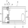
도 2내지 도 6은 본 발명의 제 1실시 예이다. 도 2는 보호소자를 갖는 발광소자를 나타낸 평면도이며, 도 3은 도 2의 사시도이고, 도 4는 도 3의 B-B 단면도이며, 도 5는 도 3의 C-C 단면도이고, 도 6은 도 2의 소자를 개념적 구조로 나타낸 도면이다.2 to 6 show a first embodiment of the present invention. 2 is a plan view illustrating a light emitting device having a protection device, FIG. 3 is a perspective view of FIG. 2, FIG. 4 is a sectional view taken along line BB of FIG. 3, FIG. 5 is a sectional view taken along line CC of FIG. 3, and FIG. Is a diagram showing a conceptual structure.
먼저 도 2 및 도 3을 참조하면, 기판(310) 상에는 발광소자(300)와 보호소자(400)가 동일한 적층 구조를 갖도록 형성되고, 발광소자(300)의 타측으로 보호소자(400)가 발광소자로부터 분할된 구조이다. 여기서, 상기 기판(310)은 예컨대 사파이어 등과 같은 절연성 기판으로 이루어진다.First, referring to FIGS. 2 and 3, the
그리고, 분할되는 두 소자(300,400) 사이의 경계부(490)에는 절연층(390)이 형성되어 두 소자 사이를 전기적으로 격리시켜 준다.In addition, an
상기 발광소자(300)는 npn 타입의 질화물 반도체 발광 소자로 형성되며, 상기 보호소자(400)는 역 방향으로 인가되는 전압에 의해 상기 발광소자를 보호하기 위한 소자로서 예컨대, npn 구조의 다이오드로 이루어진다. 즉, 발광소자(300) 및 보호소자(400)는 동일한 npn 구조를 갖는다.The
상기 발광소자(300)는 제 1연결배선(361)에 의해 보호소자(400)의 제 1도전형 반도체층(420)과 연결되며, 상기 보호소자(400)는 제 2연결배선(461)에 의해 발광소자(300)의 제 1도전형 반도체층(320)과 연결된다.The
그리고, 상기 제 1연결배선(361) 및 제 2연결배선(461)은 금속층으로 투명전극(350,450), 제 1도전형 반도체층(320,420), 그리고 절연층(390) 상에 형성된다.The
그리고, 제 1연결배선(361)의 일측에는 상기 발광소자(300)의 투명전극(350) 상에 제 1본딩패드(360)가 형성되며, 제 2연결배선(461)의 타측에는 상기 보호소자(400)의 투명전극(450) 상에 제 2본딩패드(460)가 형성된다.In addition, a
상기 보호소자(400) 상에 제 2본딩패드(460)를 형성함으로써, 제 2본딩패드(460)의 크기 만큼 발광소자의 발광 영역을 확보할 수 있으며, 정전기 방전 보호소 자를 갖는 발광 소자에서의 광 효율이 저하되는 것을 방지할 수 있다.By forming the
구체적으로, 도 3 내지 도 6을 참조하여 보호소자를 갖는 질화물 반도체 발광소자의 구조에 대해 설명하면 다음과 같다.Specifically, the structure of the nitride semiconductor light emitting device having the protection device will be described with reference to FIGS. 3 to 6 as follows.
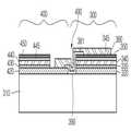
발광소자(300) 및 보호소자(400)는 기판(310) 상에 제 1도전형 반도체층 (320,420), 활성층(330,430), 제 2도전형 반도체층(340,440), 제 3도전형 반도체층(345,445), 투명전극(350,450)이 형성된다.The
상기 기판(310) 상에 형성되는 제 1도전형 반도체층(320,420)은 n-GaN층이며, 상기 제 1도전형 반도체층(320,420) 상에 형성되는 활성층(330,430)은 InGaN-QW(Quantumn Well)을 포함한다. 상기 활성층 상에 형성되는 제 2도전형 반도체층(340,440)은p-GaN층이며, 상기 제 2도전형 반도체층(340,440) 상에 형성되는 제 3도전형 반도체층(345,445)은n-GaN층이다.The first
그리고 제 3도전형 반도체층(340,440)의 표면에는 투명 전극(Transparent Electrode)(350,450)이 선택적으로 형성된다. 여기서, 상기 투명전극은 투과성 산화막으로서 ITO, ZnOx, Al doped ZnOx, RuOx, TiOx, IrOx 등 중에서 적어도 하나 이상으로 사용할 수 있다.
상기 제 1 내지 제 3도전형 반도체층(320,340,345)(420,440,445)은 MOCVD(Metal Organic Chemical Vapor Deposition)법 등의 공정을 이용하여 성장될 수 있다. 또한 제 1도전형 반도체층(320,420)과 기판 사이에는 격자정합을 향상시키기 위해, 상기 기판(310)의 상부에 AlN/GaN와 같은 버퍼층(미도시)을 더 형성할 수 도 있다. 여기서, 상기 제 3도전형 반도체층(345,445)은 오믹 접촉(ohmic contact)을 위한 층이다.The first to third
그리고, 발광소자(300) 및 보호소자(400)의 사이의 경계부(490)에는 에칭 공정에 의해 기판 상면이 노출되어 발광소자 및 보호소자가 전기적으로 분리되며, 상기 경계부 인접 부분에는 상기 에칭 공정에 의해 두 소자의 제1도전형 반도체층(320,420)이 각각 노출된다.The upper surface of the substrate is exposed to the
상기 경계부(490) 및 그 주변에는 소자간 및 다른 층간의 절연을 위해 절연층(passivation layer)(390)이 형성된다. 상기 절연층(390)은 경계부(490) 및 그 주변에 위치한 기판(310)의 상면, 보호소자(400)의 제1도전형 반도체층(420) 및 투명전극(450), 발광소자(300)의 투명전극(350) 및 제 1도전형 반도체층(320)의 노출 부분에 부분적으로 적층된다. A
그리고, 상기 발광소자(300) 및 보호소자(400)를 전기적으로 연결시켜 주기 위한 제 1 및 제2 연결배선(361,461)이 형성된다. 상기 제 1 연결배선(361)은 절연층(390), 발광소자의 투명 전극(350) 및 보호소자의 제1도전형 반도체층(420) 상에 형성되며, 이때 상기 제 1연결배선(361)의 일측에 소정 크기 및 형상을 갖는 제 1본딩 패드(360)가 형성된다.In addition, first and
상기 제 2연결배선(461)은 보호소자의 투명전극(450), 절연층(390), 발광소자의 제1도전형 반도체층(320) 상에 금속층으로 형성되며, 이때 상기 제 2연결배선(461)의 타측에 소정 크기 및 형상을 갖는 제 2본딩패드(460)가 형성된다.The
상기의 투명 전극(350,450) 상에 형성되는 연결배선(361,461) 또는 본딩 패드(360,460)는 상기 투명 전극(350,450)의 통해 그 하부의 제 3도전형 반도체층 (345,4445)과 전기적으로 연결된다.The connection wirings 361 and 461 or the
이에 따라 제 1연결배선(361)은 n-GaN층인 제 1 및 제 3도전형 반도체층(420,345)에 전기적으로 연결되며, 제 2연결배선(461)은 n-GaN인 제 1 및 제 3도전형 반도체층(320,445)에 전기적으로 연결된다.Accordingly, the
또한 제 1본딩패드(360)는 제 1연결배선(361)의 일측으로 발광소자(300)에 형성되고, 제2본딩패드(460)는 제 2연결배선(461)의 타측으로 보호소자(400)에 형성됨으로써, 보호소자를 갖는 발광소자에 상기 본딩패드(360,460)를 통해 와이어 본딩된다. 이러한 제 1 및 제 2본딩패드(360,460)는 금속층으로서 상기의 연결배선(361,461)과 함께 형성될 수도 있다.In addition, the
도 6을 참조하면, 제 1연결배선(361)은 발광소자의 투명전극(450) 및 보호소자의 제 1도전형 반도체층(420)을 전기적으로 연결해 주고, 제 1연결배선(320)에 형성된 1본딩패드(360)는 발광소자의 애노드(A) 단자로 작용하게 된다.Referring to FIG. 6, the
상기 제 2연결배선(461)은 보호소자의 투명전극(450) 및 발광소자의 제 1도전형 반도체층(320)을 전기적으로 연결해 주고, 제 2연결배선(461)에 형성된 제 2본딩패드(460)는 발광소자의 캐소드(K) 단자로 작용하게 된다.The
이러한 제 1실시 예의 동작은 다음과 같다. 도 4 내지 도 6을 참조하면, 제 1 본딩패드(360)가 애노드로 동작하고 제 2 본딩패드(460)가 캐소드로 동작하면, 제 3도전형 반도체층(345)은 P형 캐리어(carrier)가 외부에서 소자 내부로 유입될 때 상기 제 3도전형 반도체층(345)과 상기 제2 도전형 반도체층(340) 사이에 역전형 그레이딩(grading)을 형성시켜 줌으로써, 전극 접촉층의 역할을 수행하게 된다.The operation of this first embodiment is as follows. 4 to 6, when the
발광소자(300)는 정상 동작을 하게 되며 저전압 구동이 가능하게 된다. 이때 보호소자(400)는 제 1도전형 반도체층(420)에 애노드가 연결되어서 역 방향 전압이 인가되기 때문에 소자가 동작하지 않는 상태가 된다. 만약, 역 방향 전압이나 정전기의 역방향 전압이 순간적으로 상기 발광소자(300)에 인가되면, 상기 발광소자(300)는 역 방향 전압이 걸리게 되어 동작하지 않게 된다. 즉, 역 방향 전압이 보호소자(400)를 동작시켜 주어, 발광소자(300)를 안전하게 보호할 수 있게 된다.The
발광소자(300)에는 캐소드와 연결될 본딩 패드(460)가 포함되지 않으므로, 발광소자 영역의 크기를 상기 보호소자 상에 형성되는 본딩패드(460)의 크기만큼 더 확보할 수 있다.Since the
여기서, 발광소자(300)의 영역에는 하나의 와이어 본딩 패드가 포함된다. 이러한 정전기방전 보호 특성을 가지는 발광소자(300)는 다이오드의 실장이 불가능한 초 박형 고휘도 패키지 제품 및 보호소자의 실장이 필요한 패키지 제품에 사용될 수 있다.Here, one wire bonding pad is included in an area of the
또한 본 발명은 제 1 및 제 2본딩패드를 제 1실시 예와 반대의 구조로 구현할 수도 있다. 예를 들면, 발광소자의 제 1도전형 반도체층에 제 1본딩패드를 형성하고, 보호소자의 제 1도전형 반도체층에 제 2본딩패드를 형성할 수도 있다.In addition, the present invention may be implemented in a structure opposite to that of the first and second bonding pads. For example, the first bonding pad may be formed on the first conductive semiconductor layer of the light emitting device, and the second bonding pad may be formed on the first conductive semiconductor layer of the protective device.
[제 2실시 예]Second Embodiment
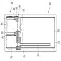
도 7 및 도 8은 본 발명의 제2실시 예이다. 도 7은 보호소자를 갖는 발광소자의 평면도이며, 도 8은 도 7의 소자를 개념적으로 나타낸 도면이다. 이러한 제 2실시 예는 보호소자에 두 개의 본딩 패드를 형성한 구조로서, 제 1실시 예와 동일 한 부분에 대해서는 중복 설명은 생략하기로 한다.7 and 8 illustrate a second embodiment of the present invention. 7 is a plan view of a light emitting device having a protection device, and FIG. 8 is a view conceptually illustrating the device of FIG. 7. The second embodiment has a structure in which two bonding pads are formed in the protection device, and overlapping description of the same parts as in the first embodiment will be omitted.
도 7은 본 발명의 제 1실시 예와 동일한 적층 구조를 가지게 되며, 보호소자에 2개의 와이어 본딩 패드를 포함하는 구성이다.7 has the same laminated structure as the first embodiment of the present invention, and includes two wire bonding pads in the protection device.
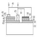
도 7및 도 8을 참조하면, 보호소자(400)를 포함하는 영역(500)에는 일측으로 제 1 본딩패드(460')가 형성되며, 타측으로 제 2 본딩패드(470')가 형성된다. 상기 제 1본딩 패드(460')는 투명전극(450)의 상면에 형성되며, 상기 제 2본딩패드(470')는 제 1도전형 반도체층(420)의 상면에 형성된다.7 and 8, the
제 1 및 제 2본딩패드(460',470')는 동일한 크기의 영역으로 분할되거나 서로 다른 크기로 형성될 수 있으며, 제 1 및 제 2연결배선(361,461)에 의해 발광소자(300)와 전기적으로 연결된다.The first and
구체적으로 설명하면, 상기 제 1연결배선(361)은 보호소자(400)의 제 1도전형 반도체층(420) 상면 및 발광소자(300)의 투명전극(350) 상면에 형성되어, 보호소자(400)와 발광소자(300)의 n형 반도체층 상호간을 전기적으로 연결해 준다. 상기 보호소자 영역의 제 1연결배선(361)에 형성된 제 1본딩 패드(470')는 발광소자의 애노드(A) 단자로 작용하게 된다.In detail, the
상기 제 2연결배선(461)은 보호소자(400)의 투명전극 상면 및 발광소자(300)의 제 1도전형 반도체층(320) 상면에 형성되어, 보호소자 및 발광소자의 n형 반도체층 상호간을 전기적으로 연결시켜 준다. 상기 보호소자 영역의 제2연결배선(461)에 형성된 제 2본딩패드(460')는 캐소드(K) 단자로 작용하게 된다.The
이와 같이 정전기방전 보호소자(400)에 두 개의 와이어 본딩 패드(460', 470')를 모두 형성하고, 두 개의 연결배선에 의해 발광소자(300) 및 보호소자(400)의 양 극성을 회로적으로 각각 연결시켜 줌으로써, 보호소자를 갖는 발광소자로 동작할 수 있다. 또한 발광소자 영역이 아닌 보호소자 상에 본딩패드를 형성함으로써 발광 영역을 증가시켜 줄 수 있다.As such, two
또한 본 발명은 발광소자 영역이 아닌 보호소자 영역 내에서 보호소자 상에 하나 또는 두 개의 본딩패드를 형성함으로써, 보호 소자 이외의 영역에 별도의 본딩 패드 영역을 더 마련하지 않아도 되는 효과가 있다.In addition, according to the present invention, by forming one or two bonding pads on the protection device in the protection device area instead of the light emitting device area, there is an effect of not having to provide a separate bonding pad area in the area other than the protection device.
이제까지 본 발명에 대하여 그 바람직한 실시 예를 중심으로 살펴보았으며, 본 발명이 속하는 기술분야에서 통상의 지식을 가진 자는 본 발명의 본질적 기술 범위 내에서 상기 본 발명의 상세한 설명과 다른 형태의 실시 예들을 구현할 수 있을 것이다. 여기서 본 발명의 본질적 기술범위는 특허청구범위에 나타나 있으며, 그와 동등한 범위 내에 있는 모든 차이점은 본 발명에 포함된 것으로 해석되어야 할 것이다.So far, the present invention has been described with reference to the preferred embodiments, and those skilled in the art to which the present invention pertains to the detailed description of the present invention and other forms of embodiments within the essential technical scope of the present invention. Could be implemented. Here, the essential technical scope of the present invention is shown in the claims, and all differences within the equivalent range will be construed as being included in the present invention.
본 발명에 따른 정전기방전 보호소자를 포함하는 발광소자 및 그 제조방법에 의하면, 정전기 보호특성을 갖는 발광 다이오드를 제공함으로써, 높은 정전기방전 특성이 요하는 발광 다이오드 패키지 제품에 응용이 가능한 장점이 있다.According to the light emitting device including the electrostatic discharge protection device and the manufacturing method thereof according to the present invention, by providing a light emitting diode having the electrostatic protection characteristics, there is an advantage that can be applied to a light emitting diode package product requiring high electrostatic discharge characteristics.
본 발명의 발광소자는 보호 소자의 실장이 불가능한 발광 다이오드 패키지 제품에 사용됨으로써, 다양한 패키지 제품에 응용이 가능한 효과가 있다.Since the light emitting device of the present invention is used in a light emitting diode package product in which the protection device cannot be mounted, the light emitting device can be applied to various package products.
본 발명은 정전기방전 보호특성을 가지는 발광소자에서 정전기방전 보호소자에 의해 광 효율이 저하되는 문제를 해결하여, 광 효율이 저하되지 않는 높은 정전기방전 보호특성을 가지는 질화물 반도체 발광 다이오드를 제공할 수 있다.The present invention solves the problem that the light efficiency is lowered by the electrostatic discharge protection device in the light emitting device having the electrostatic discharge protection characteristics, it is possible to provide a nitride semiconductor light emitting diode having a high electrostatic discharge protection characteristics that does not reduce the light efficiency. .
Claims (12)
Translated fromKoreanPriority Applications (6)
| Application Number | Priority Date | Filing Date | Title |
|---|---|---|---|
| KR1020060027225AKR100765075B1 (en) | 2006-03-26 | 2006-03-26 | Nitride semiconductor light emitting device and manufacturing method thereof |
| US12/086,140US8188504B2 (en) | 2006-03-26 | 2007-03-22 | Light-emitting device and method for manufacturing the same including a light-emitting device and a protection device electrically connected by a connecting line |
| JP2009502660AJP2009531852A (en) | 2006-03-26 | 2007-03-22 | Nitride semiconductor light emitting device and manufacturing method thereof |
| CN2007800002448ACN101313418B (en) | 2006-03-26 | 2007-03-22 | Light emitting device and method of manufacturing light emitting device |
| PCT/KR2007/001392WO2007111436A1 (en) | 2006-03-26 | 2007-03-22 | Light-emitting device and method for manufacturing the same |
| TW096110229ATWI459580B (en) | 2006-03-26 | 2007-03-23 | Light emitting device and method of manufacturing same |
Applications Claiming Priority (1)
| Application Number | Priority Date | Filing Date | Title |
|---|---|---|---|
| KR1020060027225AKR100765075B1 (en) | 2006-03-26 | 2006-03-26 | Nitride semiconductor light emitting device and manufacturing method thereof |
Publications (2)
| Publication Number | Publication Date |
|---|---|
| KR20070096541A KR20070096541A (en) | 2007-10-02 |
| KR100765075B1true KR100765075B1 (en) | 2007-10-09 |
Family
ID=38541333
Family Applications (1)
| Application Number | Title | Priority Date | Filing Date |
|---|---|---|---|
| KR1020060027225AExpired - Fee RelatedKR100765075B1 (en) | 2006-03-26 | 2006-03-26 | Nitride semiconductor light emitting device and manufacturing method thereof |
Country Status (6)
| Country | Link |
|---|---|
| US (1) | US8188504B2 (en) |
| JP (1) | JP2009531852A (en) |
| KR (1) | KR100765075B1 (en) |
| CN (1) | CN101313418B (en) |
| TW (1) | TWI459580B (en) |
| WO (1) | WO2007111436A1 (en) |
Families Citing this family (80)
| Publication number | Priority date | Publication date | Assignee | Title |
|---|---|---|---|---|
| US8871024B2 (en)* | 2008-06-05 | 2014-10-28 | Soraa, Inc. | High pressure apparatus and method for nitride crystal growth |
| US8097081B2 (en) | 2008-06-05 | 2012-01-17 | Soraa, Inc. | High pressure apparatus and method for nitride crystal growth |
| US9157167B1 (en) | 2008-06-05 | 2015-10-13 | Soraa, Inc. | High pressure apparatus and method for nitride crystal growth |
| US8430958B2 (en)* | 2008-08-07 | 2013-04-30 | Soraa, Inc. | Apparatus and method for seed crystal utilization in large-scale manufacturing of gallium nitride |
| US10036099B2 (en) | 2008-08-07 | 2018-07-31 | Slt Technologies, Inc. | Process for large-scale ammonothermal manufacturing of gallium nitride boules |
| US8979999B2 (en) | 2008-08-07 | 2015-03-17 | Soraa, Inc. | Process for large-scale ammonothermal manufacturing of gallium nitride boules |
| US8021481B2 (en) | 2008-08-07 | 2011-09-20 | Soraa, Inc. | Process and apparatus for large-scale manufacturing of bulk monocrystalline gallium-containing nitride |
| US7976630B2 (en) | 2008-09-11 | 2011-07-12 | Soraa, Inc. | Large-area seed for ammonothermal growth of bulk gallium nitride and method of manufacture |
| US8354679B1 (en) | 2008-10-02 | 2013-01-15 | Soraa, Inc. | Microcavity light emitting diode method of manufacture |
| US8455894B1 (en) | 2008-10-17 | 2013-06-04 | Soraa, Inc. | Photonic-crystal light emitting diode and method of manufacture |
| US8963175B2 (en) | 2008-11-06 | 2015-02-24 | Samsung Electro-Mechanics Co., Ltd. | Light emitting device and method of manufacturing the same |
| JP5017239B2 (en)* | 2008-11-14 | 2012-09-05 | サムソン エルイーディー カンパニーリミテッド. | Light emitting device and manufacturing method thereof |
| US8461071B2 (en)* | 2008-12-12 | 2013-06-11 | Soraa, Inc. | Polycrystalline group III metal nitride with getter and method of making |
| US8987156B2 (en) | 2008-12-12 | 2015-03-24 | Soraa, Inc. | Polycrystalline group III metal nitride with getter and method of making |
| USRE47114E1 (en) | 2008-12-12 | 2018-11-06 | Slt Technologies, Inc. | Polycrystalline group III metal nitride with getter and method of making |
| US9543392B1 (en) | 2008-12-12 | 2017-01-10 | Soraa, Inc. | Transparent group III metal nitride and method of manufacture |
| US8878230B2 (en) | 2010-03-11 | 2014-11-04 | Soraa, Inc. | Semi-insulating group III metal nitride and method of manufacture |
| US20110100291A1 (en)* | 2009-01-29 | 2011-05-05 | Soraa, Inc. | Plant and method for large-scale ammonothermal manufacturing of gallium nitride boules |
| US8247886B1 (en) | 2009-03-09 | 2012-08-21 | Soraa, Inc. | Polarization direction of optical devices using selected spatial configurations |
| US8299473B1 (en) | 2009-04-07 | 2012-10-30 | Soraa, Inc. | Polarized white light devices using non-polar or semipolar gallium containing materials and transparent phosphors |
| US8791499B1 (en) | 2009-05-27 | 2014-07-29 | Soraa, Inc. | GaN containing optical devices and method with ESD stability |
| US9000466B1 (en) | 2010-08-23 | 2015-04-07 | Soraa, Inc. | Methods and devices for light extraction from a group III-nitride volumetric LED using surface and sidewall roughening |
| US8933644B2 (en) | 2009-09-18 | 2015-01-13 | Soraa, Inc. | LED lamps with improved quality of light |
| US9293644B2 (en) | 2009-09-18 | 2016-03-22 | Soraa, Inc. | Power light emitting diode and method with uniform current density operation |
| US9583678B2 (en) | 2009-09-18 | 2017-02-28 | Soraa, Inc. | High-performance LED fabrication |
| CN102630349B (en) | 2009-09-18 | 2017-06-13 | 天空公司 | Power light emitting diode and method of operating with current density |
| US8435347B2 (en) | 2009-09-29 | 2013-05-07 | Soraa, Inc. | High pressure apparatus with stackable rings |
| WO2011040703A2 (en) | 2009-09-30 | 2011-04-07 | 주식회사 세미콘라이트 | Semiconductor light emitting device |
| US9175418B2 (en) | 2009-10-09 | 2015-11-03 | Soraa, Inc. | Method for synthesis of high quality large area bulk gallium based crystals |
| US10147850B1 (en) | 2010-02-03 | 2018-12-04 | Soraa, Inc. | System and method for providing color light sources in proximity to predetermined wavelength conversion structures |
| US8905588B2 (en) | 2010-02-03 | 2014-12-09 | Sorra, Inc. | System and method for providing color light sources in proximity to predetermined wavelength conversion structures |
| US8740413B1 (en) | 2010-02-03 | 2014-06-03 | Soraa, Inc. | System and method for providing color light sources in proximity to predetermined wavelength conversion structures |
| US9450143B2 (en) | 2010-06-18 | 2016-09-20 | Soraa, Inc. | Gallium and nitrogen containing triangular or diamond-shaped configuration for optical devices |
| US9564320B2 (en) | 2010-06-18 | 2017-02-07 | Soraa, Inc. | Large area nitride crystal and method for making it |
| KR101711960B1 (en)* | 2010-07-01 | 2017-03-06 | 삼성전자주식회사 | Semiconductor light emitting device |
| US20120007102A1 (en)* | 2010-07-08 | 2012-01-12 | Soraa, Inc. | High Voltage Device and Method for Optical Devices |
| JP2012023280A (en)* | 2010-07-16 | 2012-02-02 | Seiwa Electric Mfg Co Ltd | Semiconductor light-emitting element, light-emitting device, lighting device, display device, signal light and road information device |
| US8729559B2 (en) | 2010-10-13 | 2014-05-20 | Soraa, Inc. | Method of making bulk InGaN substrates and devices thereon |
| US8786053B2 (en) | 2011-01-24 | 2014-07-22 | Soraa, Inc. | Gallium-nitride-on-handle substrate materials and devices and method of manufacture |
| JP5549629B2 (en)* | 2011-03-30 | 2014-07-16 | サンケン電気株式会社 | Light emitting element |
| JP5772213B2 (en)* | 2011-05-20 | 2015-09-02 | サンケン電気株式会社 | Light emitting element |
| TWI488337B (en)* | 2011-07-12 | 2015-06-11 | Huga Optotech Inc | Light-emitting device and fabrication method thereof |
| US8492185B1 (en) | 2011-07-14 | 2013-07-23 | Soraa, Inc. | Large area nonpolar or semipolar gallium and nitrogen containing substrate and resulting devices |
| US8686431B2 (en) | 2011-08-22 | 2014-04-01 | Soraa, Inc. | Gallium and nitrogen containing trilateral configuration for optical devices |
| US9694158B2 (en) | 2011-10-21 | 2017-07-04 | Ahmad Mohamad Slim | Torque for incrementally advancing a catheter during right heart catheterization |
| US10029955B1 (en) | 2011-10-24 | 2018-07-24 | Slt Technologies, Inc. | Capsule for high pressure, high temperature processing of materials and methods of use |
| US8912025B2 (en) | 2011-11-23 | 2014-12-16 | Soraa, Inc. | Method for manufacture of bright GaN LEDs using a selective removal process |
| TWD149845S (en)* | 2011-11-24 | 2012-10-21 | 晶元光電股份有限公司 | Light-emitting diode array |
| US8482104B2 (en) | 2012-01-09 | 2013-07-09 | Soraa, Inc. | Method for growth of indium-containing nitride films |
| TWD152513S (en)* | 2012-02-03 | 2013-03-21 | 晶元光電股份有限公司 | Light-emitting diode array |
| JP2015509669A (en) | 2012-03-06 | 2015-03-30 | ソラア インコーポレーテッドSoraa Inc. | Light emitting diode with low refractive index material layer to reduce guided light effect |
| USD684550S1 (en)* | 2012-06-08 | 2013-06-18 | Epistar Corporation | Light-emitting diode array |
| US8971368B1 (en) | 2012-08-16 | 2015-03-03 | Soraa Laser Diode, Inc. | Laser devices having a gallium and nitrogen containing semipolar surface orientation |
| US9978904B2 (en) | 2012-10-16 | 2018-05-22 | Soraa, Inc. | Indium gallium nitride light emitting devices |
| US8802471B1 (en) | 2012-12-21 | 2014-08-12 | Soraa, Inc. | Contacts for an n-type gallium and nitrogen substrate for optical devices |
| USD716238S1 (en)* | 2012-12-31 | 2014-10-28 | Epistar Corporation | Light-emitting diode array |
| TWI549322B (en)* | 2013-04-10 | 2016-09-11 | 映瑞光電科技(上海)有限公司 | Integrated LED component combined with epitaxial structure and package substrate and manufacturing method thereof |
| US8994033B2 (en) | 2013-07-09 | 2015-03-31 | Soraa, Inc. | Contacts for an n-type gallium and nitrogen substrate for optical devices |
| USD718259S1 (en)* | 2013-08-13 | 2014-11-25 | Epistar Corporation | Light-emitting diode device |
| US9419189B1 (en) | 2013-11-04 | 2016-08-16 | Soraa, Inc. | Small LED source with high brightness and high efficiency |
| CN106062466B (en) | 2013-11-15 | 2020-01-31 | 瑞尔D斯帕克有限责任公司 | Directional backlight with light emitting element package |
| USD728494S1 (en)* | 2014-03-04 | 2015-05-05 | Epistar Corporation | Light-emitting diode array |
| USD773410S1 (en)* | 2014-10-24 | 2016-12-06 | Epistar Corporation | Light-emitting diode array |
| USD750580S1 (en)* | 2014-10-30 | 2016-03-01 | Epistar Corporation | Light-emitting diode array |
| RU2596062C1 (en) | 2015-03-20 | 2016-08-27 | Автономная Некоммерческая Образовательная Организация Высшего Профессионального Образования "Сколковский Институт Науки И Технологий" | Method for correction of eye image using machine learning and method of machine learning |
| USD775090S1 (en)* | 2015-04-23 | 2016-12-27 | Seoul Viosys Co., Ltd. | Light emitting diode |
| TWD177985S (en)* | 2015-08-12 | 2016-09-01 | 晶元光電股份有限公司 | Portion of light-emitting diode unit |
| USD845920S1 (en) | 2015-08-12 | 2019-04-16 | Epistar Corporation | Portion of light-emitting diode unit |
| CN114143495B (en) | 2016-01-05 | 2025-07-15 | 瑞尔D斯帕克有限责任公司 | Gaze Correction for Multi-View Images |
| EP3458897B1 (en) | 2016-05-19 | 2025-04-02 | RealD Spark, LLC | Wide angle imaging directional backlights |
| US10425635B2 (en) | 2016-05-23 | 2019-09-24 | Reald Spark, Llc | Wide angle imaging directional backlights |
| WO2018129059A1 (en) | 2017-01-04 | 2018-07-12 | Reald Spark, Llc | Optical stack for imaging directional backlights |
| US10174438B2 (en) | 2017-03-30 | 2019-01-08 | Slt Technologies, Inc. | Apparatus for high pressure reaction |
| EP3607387A4 (en) | 2017-04-03 | 2020-11-25 | RealD Spark, LLC | Segmented imaging directional backlights |
| CN111183405A (en) | 2017-08-08 | 2020-05-19 | 瑞尔D斯帕克有限责任公司 | Adjust the digital representation of the head area |
| WO2019090246A1 (en) | 2017-11-06 | 2019-05-09 | Reald Spark, Llc | Privacy display apparatus |
| CN108110024A (en)* | 2018-01-16 | 2018-06-01 | 福建兆元光电有限公司 | A kind of semiconductor light-emitting elements |
| KR102759510B1 (en) | 2018-01-25 | 2025-02-04 | 리얼디 스파크, 엘엘씨 | Touchscreen for privacy display |
| KR102551746B1 (en)* | 2018-06-05 | 2023-07-07 | 삼성전자주식회사 | Light emitting module |
| TWD198613S (en)* | 2018-08-08 | 2019-07-11 | 晶元光電股份有限公司 | Portion of light-emitting diode |
Citations (4)
| Publication number | Priority date | Publication date | Assignee | Title |
|---|---|---|---|---|
| US6547249B2 (en) | 2001-03-29 | 2003-04-15 | Lumileds Lighting U.S., Llc | Monolithic series/parallel led arrays formed on highly resistive substrates |
| JP2003243701A (en) | 2003-03-20 | 2003-08-29 | Toyoda Gosei Co Ltd | Iii nitride-based semiconductor light emitting element |
| KR20050076680A (en)* | 2004-01-20 | 2005-07-26 | 옵토 테크 코포레이션 | Light-emitting diode with prevention of electrostatic damage |
| KR20060086695A (en)* | 2005-01-27 | 2006-08-01 | 삼성전기주식회사 | A gallium nitride-based light emitting device having an ESD protection LED and a method of manufacturing the same |
Family Cites Families (9)
| Publication number | Priority date | Publication date | Assignee | Title |
|---|---|---|---|---|
| US6054716A (en) | 1997-01-10 | 2000-04-25 | Rohm Co., Ltd. | Semiconductor light emitting device having a protecting device |
| JP3787202B2 (en) | 1997-01-10 | 2006-06-21 | ローム株式会社 | Semiconductor light emitting device |
| JP3509809B2 (en)* | 2002-04-30 | 2004-03-22 | 住友電気工業株式会社 | Submount and semiconductor device |
| US7341880B2 (en)* | 2003-09-17 | 2008-03-11 | Luminus Devices, Inc. | Light emitting device processes |
| TWI229463B (en)* | 2004-02-02 | 2005-03-11 | South Epitaxy Corp | Light-emitting diode structure with electro-static discharge protection |
| JP4577497B2 (en)* | 2004-02-02 | 2010-11-10 | サンケン電気株式会社 | Composite semiconductor device of semiconductor light emitting element and protective element |
| US20050179042A1 (en)* | 2004-02-13 | 2005-08-18 | Kopin Corporation | Monolithic integration and enhanced light extraction in gallium nitride-based light-emitting devices |
| US7064353B2 (en)* | 2004-05-26 | 2006-06-20 | Philips Lumileds Lighting Company, Llc | LED chip with integrated fast switching diode for ESD protection |
| JP4841550B2 (en)* | 2004-06-30 | 2011-12-21 | ソウル オプト デバイス カンパニー リミテッド | LIGHT EMITTING ELEMENT, ITS MANUFACTURING METHOD, AND LIGHT EMITTING DEVICE USING THE SAME |
- 2006
- 2006-03-26KRKR1020060027225Apatent/KR100765075B1/ennot_activeExpired - Fee Related
- 2007
- 2007-03-22WOPCT/KR2007/001392patent/WO2007111436A1/enactiveApplication Filing
- 2007-03-22CNCN2007800002448Apatent/CN101313418B/ennot_activeExpired - Fee Related
- 2007-03-22USUS12/086,140patent/US8188504B2/ennot_activeExpired - Fee Related
- 2007-03-22JPJP2009502660Apatent/JP2009531852A/ennot_activeCeased
- 2007-03-23TWTW096110229Apatent/TWI459580B/ennot_activeIP Right Cessation
Patent Citations (4)
| Publication number | Priority date | Publication date | Assignee | Title |
|---|---|---|---|---|
| US6547249B2 (en) | 2001-03-29 | 2003-04-15 | Lumileds Lighting U.S., Llc | Monolithic series/parallel led arrays formed on highly resistive substrates |
| JP2003243701A (en) | 2003-03-20 | 2003-08-29 | Toyoda Gosei Co Ltd | Iii nitride-based semiconductor light emitting element |
| KR20050076680A (en)* | 2004-01-20 | 2005-07-26 | 옵토 테크 코포레이션 | Light-emitting diode with prevention of electrostatic damage |
| KR20060086695A (en)* | 2005-01-27 | 2006-08-01 | 삼성전기주식회사 | A gallium nitride-based light emitting device having an ESD protection LED and a method of manufacturing the same |
Also Published As
| Publication number | Publication date |
|---|---|
| CN101313418A (en) | 2008-11-26 |
| WO2007111436A1 (en) | 2007-10-04 |
| TW200739972A (en) | 2007-10-16 |
| JP2009531852A (en) | 2009-09-03 |
| US20100072504A1 (en) | 2010-03-25 |
| US8188504B2 (en) | 2012-05-29 |
| KR20070096541A (en) | 2007-10-02 |
| CN101313418B (en) | 2011-06-01 |
| TWI459580B (en) | 2014-11-01 |
Similar Documents
| Publication | Publication Date | Title |
|---|---|---|
| KR100765075B1 (en) | Nitride semiconductor light emitting device and manufacturing method thereof | |
| US11335838B2 (en) | Light emitting apparatus | |
| US8450762B2 (en) | Light emitting device | |
| KR101154709B1 (en) | Light emitting device, method for fabricating the light emitting device, light emitting device package and lighting system | |
| CN104112757B (en) | Luminescent device, light emitting device package, the manufacture method and illuminator of luminescent device | |
| EP2348547A2 (en) | Light emitting device, method of manufacturing the same, light emitting device package and lighting system | |
| JPH10200159A (en) | Semiconductor light emitting element | |
| US8829538B2 (en) | Light emitting device package | |
| KR20080087251A (en) | Light Emitting Diodes With Capacitors | |
| KR20090010623A (en) | Light emitting diode device | |
| KR20170133746A (en) | Light emitting device | |
| KR20170027592A (en) | Light emitting device and method of fabricating the same | |
| KR101040140B1 (en) | Semiconductor light emitting device array and manufacturing method thereof | |
| US20050127374A1 (en) | Light-emitting device and forming method thereof | |
| TWI824880B (en) | Display device | |
| KR101381986B1 (en) | Light emitting diode having capacitor | |
| KR102531520B1 (en) | Light emitting device | |
| KR101239855B1 (en) | Light emitting diode package having zenor diode therein | |
| KR20120058350A (en) | Light emitting device | |
| CN108110024A (en) | A kind of semiconductor light-emitting elements | |
| KR20170039387A (en) | Light emitting device | |
| KR20160147304A (en) | Light emitting device and method for fabricating the same |
Legal Events
| Date | Code | Title | Description |
|---|---|---|---|
| A201 | Request for examination | ||
| PA0109 | Patent application | St.27 status event code:A-0-1-A10-A12-nap-PA0109 | |
| PA0201 | Request for examination | St.27 status event code:A-1-2-D10-D11-exm-PA0201 | |
| PN2301 | Change of applicant | St.27 status event code:A-3-3-R10-R13-asn-PN2301 St.27 status event code:A-3-3-R10-R11-asn-PN2301 | |
| R18-X000 | Changes to party contact information recorded | St.27 status event code:A-3-3-R10-R18-oth-X000 | |
| D13-X000 | Search requested | St.27 status event code:A-1-2-D10-D13-srh-X000 | |
| D14-X000 | Search report completed | St.27 status event code:A-1-2-D10-D14-srh-X000 | |
| E902 | Notification of reason for refusal | ||
| PE0902 | Notice of grounds for rejection | St.27 status event code:A-1-2-D10-D21-exm-PE0902 | |
| P11-X000 | Amendment of application requested | St.27 status event code:A-2-2-P10-P11-nap-X000 | |
| P13-X000 | Application amended | St.27 status event code:A-2-2-P10-P13-nap-X000 | |
| E701 | Decision to grant or registration of patent right | ||
| PE0701 | Decision of registration | St.27 status event code:A-1-2-D10-D22-exm-PE0701 | |
| GRNT | Written decision to grant | ||
| PR0701 | Registration of establishment | St.27 status event code:A-2-4-F10-F11-exm-PR0701 | |
| PR1002 | Payment of registration fee | St.27 status event code:A-2-2-U10-U11-oth-PR1002 Fee payment year number:1 | |
| PG1501 | Laying open of application | St.27 status event code:A-1-1-Q10-Q12-nap-PG1501 | |
| PG1601 | Publication of registration | St.27 status event code:A-4-4-Q10-Q13-nap-PG1601 | |
| P22-X000 | Classification modified | St.27 status event code:A-4-4-P10-P22-nap-X000 | |
| PN2301 | Change of applicant | St.27 status event code:A-5-5-R10-R13-asn-PN2301 St.27 status event code:A-5-5-R10-R11-asn-PN2301 | |
| R18-X000 | Changes to party contact information recorded | St.27 status event code:A-5-5-R10-R18-oth-X000 | |
| PR1001 | Payment of annual fee | St.27 status event code:A-4-4-U10-U11-oth-PR1001 Fee payment year number:4 | |
| PR1001 | Payment of annual fee | St.27 status event code:A-4-4-U10-U11-oth-PR1001 Fee payment year number:5 | |
| FPAY | Annual fee payment | Payment date:20120905 Year of fee payment:6 | |
| PR1001 | Payment of annual fee | St.27 status event code:A-4-4-U10-U11-oth-PR1001 Fee payment year number:6 | |
| FPAY | Annual fee payment | Payment date:20130905 Year of fee payment:7 | |
| PR1001 | Payment of annual fee | St.27 status event code:A-4-4-U10-U11-oth-PR1001 Fee payment year number:7 | |
| PR1001 | Payment of annual fee | St.27 status event code:A-4-4-U10-U11-oth-PR1001 Fee payment year number:8 | |
| PN2301 | Change of applicant | St.27 status event code:A-5-5-R10-R13-asn-PN2301 St.27 status event code:A-5-5-R10-R11-asn-PN2301 | |
| FPAY | Annual fee payment | Payment date:20150904 Year of fee payment:9 | |
| PR1001 | Payment of annual fee | St.27 status event code:A-4-4-U10-U11-oth-PR1001 Fee payment year number:9 | |
| FPAY | Annual fee payment | Payment date:20160905 Year of fee payment:10 | |
| PR1001 | Payment of annual fee | St.27 status event code:A-4-4-U10-U11-oth-PR1001 Fee payment year number:10 | |
| R18-X000 | Changes to party contact information recorded | St.27 status event code:A-5-5-R10-R18-oth-X000 | |
| FPAY | Annual fee payment | Payment date:20170905 Year of fee payment:11 | |
| PR1001 | Payment of annual fee | St.27 status event code:A-4-4-U10-U11-oth-PR1001 Fee payment year number:11 | |
| R18-X000 | Changes to party contact information recorded | St.27 status event code:A-5-5-R10-R18-oth-X000 | |
| LAPS | Lapse due to unpaid annual fee | ||
| PC1903 | Unpaid annual fee | St.27 status event code:A-4-4-U10-U13-oth-PC1903 Not in force date:20181002 Payment event data comment text:Termination Category : DEFAULT_OF_REGISTRATION_FEE | |
| PC1903 | Unpaid annual fee | St.27 status event code:N-4-6-H10-H13-oth-PC1903 Ip right cessation event data comment text:Termination Category : DEFAULT_OF_REGISTRATION_FEE Not in force date:20181002 | |
| R18-X000 | Changes to party contact information recorded | St.27 status event code:A-5-5-R10-R18-oth-X000 | |
| PN2301 | Change of applicant | St.27 status event code:A-5-5-R10-R13-asn-PN2301 St.27 status event code:A-5-5-R10-R11-asn-PN2301 | |
| P22-X000 | Classification modified | St.27 status event code:A-4-4-P10-P22-nap-X000 |