KR100764411B1 - Backlight device and liquid crystal display device - Google Patents
Backlight device and liquid crystal display deviceDownload PDFInfo
- Publication number
- KR100764411B1 KR100764411B1KR1020050088035AKR20050088035AKR100764411B1KR 100764411 B1KR100764411 B1KR 100764411B1KR 1020050088035 AKR1020050088035 AKR 1020050088035AKR 20050088035 AKR20050088035 AKR 20050088035AKR 100764411 B1KR100764411 B1KR 100764411B1
- Authority
- KR
- South Korea
- Prior art keywords
- liquid crystal
- crystal display
- display panel
- linear light
- reflector
- Prior art date
- Legal status (The legal status is an assumption and is not a legal conclusion. Google has not performed a legal analysis and makes no representation as to the accuracy of the status listed.)
- Expired - Fee Related
Links
Images


Classifications
- G—PHYSICS
- G02—OPTICS
- G02F—OPTICAL DEVICES OR ARRANGEMENTS FOR THE CONTROL OF LIGHT BY MODIFICATION OF THE OPTICAL PROPERTIES OF THE MEDIA OF THE ELEMENTS INVOLVED THEREIN; NON-LINEAR OPTICS; FREQUENCY-CHANGING OF LIGHT; OPTICAL LOGIC ELEMENTS; OPTICAL ANALOGUE/DIGITAL CONVERTERS
- G02F1/00—Devices or arrangements for the control of the intensity, colour, phase, polarisation or direction of light arriving from an independent light source, e.g. switching, gating or modulating; Non-linear optics
- G02F1/01—Devices or arrangements for the control of the intensity, colour, phase, polarisation or direction of light arriving from an independent light source, e.g. switching, gating or modulating; Non-linear optics for the control of the intensity, phase, polarisation or colour
- G02F1/13—Devices or arrangements for the control of the intensity, colour, phase, polarisation or direction of light arriving from an independent light source, e.g. switching, gating or modulating; Non-linear optics for the control of the intensity, phase, polarisation or colour based on liquid crystals, e.g. single liquid crystal display cells
- G02F1/133—Constructional arrangements; Operation of liquid crystal cells; Circuit arrangements
- G02F1/1333—Constructional arrangements; Manufacturing methods
- G02F1/1335—Structural association of cells with optical devices, e.g. polarisers or reflectors
- G02F1/1336—Illuminating devices
- G02F1/133602—Direct backlight
- G02F1/133604—Direct backlight with lamps
- G—PHYSICS
- G02—OPTICS
- G02F—OPTICAL DEVICES OR ARRANGEMENTS FOR THE CONTROL OF LIGHT BY MODIFICATION OF THE OPTICAL PROPERTIES OF THE MEDIA OF THE ELEMENTS INVOLVED THEREIN; NON-LINEAR OPTICS; FREQUENCY-CHANGING OF LIGHT; OPTICAL LOGIC ELEMENTS; OPTICAL ANALOGUE/DIGITAL CONVERTERS
- G02F1/00—Devices or arrangements for the control of the intensity, colour, phase, polarisation or direction of light arriving from an independent light source, e.g. switching, gating or modulating; Non-linear optics
- G02F1/01—Devices or arrangements for the control of the intensity, colour, phase, polarisation or direction of light arriving from an independent light source, e.g. switching, gating or modulating; Non-linear optics for the control of the intensity, phase, polarisation or colour
- G02F1/13—Devices or arrangements for the control of the intensity, colour, phase, polarisation or direction of light arriving from an independent light source, e.g. switching, gating or modulating; Non-linear optics for the control of the intensity, phase, polarisation or colour based on liquid crystals, e.g. single liquid crystal display cells
- G02F1/133—Constructional arrangements; Operation of liquid crystal cells; Circuit arrangements
- G02F1/1333—Constructional arrangements; Manufacturing methods
- G02F1/1335—Structural association of cells with optical devices, e.g. polarisers or reflectors
- G02F1/1336—Illuminating devices
- G02F1/133602—Direct backlight
- G02F1/133605—Direct backlight including specially adapted reflectors
- B—PERFORMING OPERATIONS; TRANSPORTING
- B32—LAYERED PRODUCTS
- B32B—LAYERED PRODUCTS, i.e. PRODUCTS BUILT-UP OF STRATA OF FLAT OR NON-FLAT, e.g. CELLULAR OR HONEYCOMB, FORM
- B32B2457/00—Electrical equipment
- B32B2457/20—Displays, e.g. liquid crystal displays, plasma displays
- B32B2457/202—LCD, i.e. liquid crystal displays
- G—PHYSICS
- G02—OPTICS
- G02F—OPTICAL DEVICES OR ARRANGEMENTS FOR THE CONTROL OF LIGHT BY MODIFICATION OF THE OPTICAL PROPERTIES OF THE MEDIA OF THE ELEMENTS INVOLVED THEREIN; NON-LINEAR OPTICS; FREQUENCY-CHANGING OF LIGHT; OPTICAL LOGIC ELEMENTS; OPTICAL ANALOGUE/DIGITAL CONVERTERS
- G02F2201/00—Constructional arrangements not provided for in groups G02F1/00 - G02F7/00
- G02F2201/34—Constructional arrangements not provided for in groups G02F1/00 - G02F7/00 reflector
- G—PHYSICS
- G02—OPTICS
- G02F—OPTICAL DEVICES OR ARRANGEMENTS FOR THE CONTROL OF LIGHT BY MODIFICATION OF THE OPTICAL PROPERTIES OF THE MEDIA OF THE ELEMENTS INVOLVED THEREIN; NON-LINEAR OPTICS; FREQUENCY-CHANGING OF LIGHT; OPTICAL LOGIC ELEMENTS; OPTICAL ANALOGUE/DIGITAL CONVERTERS
- G02F2203/00—Function characteristic
- G02F2203/02—Function characteristic reflective
Landscapes
- Physics & Mathematics (AREA)
- Nonlinear Science (AREA)
- Mathematical Physics (AREA)
- Chemical & Material Sciences (AREA)
- Crystallography & Structural Chemistry (AREA)
- General Physics & Mathematics (AREA)
- Optics & Photonics (AREA)
- Liquid Crystal (AREA)
- Planar Illumination Modules (AREA)
Abstract
Translated fromKoreanDescription
Translated fromKorean도 1은 본 발명에 따른 백 라이트 장치의 원리를 설명하는 주요부 확대 사시도.1 is an enlarged perspective view of an essential part for explaining the principle of a backlight device according to the present invention;
도 2는 본 발명에 따른 백 라이트 장치 및 이 백 라이트 장치를 이용한 액정 표시 장치의 제1 실시예에 따른 구성을 도시하는 주요부 단면도.Fig. 2 is a sectional view of principal parts showing a structure according to a first embodiment of a backlight device and a liquid crystal display device using the backlight device according to the present invention;
도 3은 도 2에 도시하는 백 라이트 장치의 구성의 상세를 나타내는 주요부 확대도로서, 도 3의 (a)는 단면도이며, 도 3의 (b)는 상방으로부터 보았을 때의 평면도.3 is an enlarged view of an essential part showing the details of the configuration of the backlight device shown in FIG. 2, FIG. 3A is a sectional view, and FIG. 3B is a plan view when viewed from above.
도 4는 도 3에 도시하는 백 라이트 장치를 장착한 액정 표시 장치의 구성을 도시하는 주요부 확대 단면도.4 is an enlarged cross-sectional view of an essential part showing the configuration of a liquid crystal display device equipped with the backlight device shown in FIG. 3;
도 5는 본 발명에 따른 백 라이트 장치의 반사체를 성형하는 제조 장치의 개략적 구성을 설명하는 주요부 확대 단면도로서, 도 5의 (a)는 캐비티에 수지재를 충전하여, 금형을 개방한 형(型) 개방의 상태를 나타내는 도면이며, 도 5의 (b)는 형 개방 후, 이젝터 핀에 의해 수지재로 형성된 반사체를 돌출한 상태를 나타내는 도면.FIG. 5 is an enlarged cross-sectional view of an essential part for explaining a schematic configuration of a manufacturing apparatus for forming a reflector of a backlight device according to the present invention. FIG. 5A shows a mold in which a mold is opened by filling a cavity with a resin material. Fig. 5B is a view showing a state in which the reflector formed of the resin material is projected by the ejector pin after the mold opening.
도 6은 본 발명에 따른 백 라이트 장치 및 이 백 라이트 장치를 이용한 액정 표시 장치의 제2 실시예에 따른 구성을 도시하는 주요부 단면도.Fig. 6 is a cross sectional view of principal parts showing a structure according to a second embodiment of a backlight device and a liquid crystal display device using the backlight device according to the present invention;
도 7은 본 발명에 따른 액정 표시 장치의 일례를 나타내는 상부로부터 보았을 때의 주요부 평면도.7 is a plan view of an essential part, as viewed from the top, showing an example of a liquid crystal display device according to the present invention;
도 8은 본 발명에 따른 액정 표시 장치의 일례를 나타내는 주요부 전개 사시도.8 is an exploded perspective view of an essential part showing an example of a liquid crystal display device according to the present invention;
도 9는 본 발명에 따른 액정 표시 장치를 구비한 텔레비전 수상기를 나타내는 외관도.Fig. 9 is an external view showing a television receiver equipped with a liquid crystal display device according to the present invention.
도 10은 종래의 액정 표시 장치의 구성을 도시하는 주요부 확대 단면도이다.10 is an enlarged sectional view of an essential part showing the structure of a conventional liquid crystal display.
〈도면의 주요 부분에 대한 부호의 설명〉<Explanation of symbols for main parts of drawing>
PNL : 액정 표시 패널PNL: Liquid Crystal Display Panel
SUB1 : 제1 기판SUB1: first substrate
SUB2 : 제2 기판SUB2: second substrate
POL1 : 제1 편광판POL1: first polarizer
POL2 : 제2 편광판POL2: second polarizer
OPS : 광학 보상 시트 적층체OPS: Optical Compensation Sheet Laminate
PZL : 프리즘 렌즈PZL: Prism Lens
DFS : 확산 시트DFS: Diffusion Sheet
PRS : 편광 반사 시트PRS: Polarized Reflective Sheet
BL : 백 라이트 장치BL: Backlight Device
REP : 반사판REP: Reflector
REM, REC : 반사체REM, REC: Reflector
RES : 반사막RES: Reflective Film
DTH : 오목 홈DTH: Concave Groove
VG : 밸브 게이트 구(口)VG: Valve gate mouth
FLG : 플랜지부FLG: Flange
CFL : 냉음극 형광 램프CFL: Cold Cathode Fluorescent Lamp
USM : 상측 사이드 몰드USM: Upper Side Mold
LSM : 하측 사이드 몰드LSM: Lower Side Mold
SMLD : 사이드 몰드SMLD: Side Mold
UMLD : 상측 몰드 프레임UMLD: Upper Mold Frame
LMLD : 하측 몰드 프레임LMLD: Lower Mold Frame
SMLD : 사이드 몰드SMLD: Side Mold
DSP : 표시부DSP: Display
STD : 스탠드부STD: Stand part
[특허 문헌 1] 일본 특개 제2002-82626호 공보[Patent Document 1] Japanese Patent Application Laid-Open No. 2002-82626
[특허 문헌 2] 일본 특개평6-75216호 공보[Patent Document 2] Japanese Patent Application Laid-Open No. 6-75216
본 발명은, 백 라이트 장치 및 액정 표시 장치에 관한 것으로, 특히 액정 표시 패널의 배면측에 설치되며 상기 액정 표시 패널에 광을 조사하는 선 형상 광원 직하형 백 라이트 장치 및 상기 백 라이트 장치를 이용한 액정 표시 장치에 관한 것이다.BACKGROUND OF THE INVENTION 1. Field of the Invention The present invention relates to a backlight device and a liquid crystal display device. In particular, a linear light source direct backlight device and a liquid crystal using the backlight device are provided on the back side of the liquid crystal display panel and irradiate light to the liquid crystal display panel. It relates to a display device.
최근, 퍼스널 컴퓨터, 휴대 전화기 등의 각종 정보 단말기용 모니터 혹은 텔레비전 수상기 등의 표시 수단으로서 액정 표시 장치가 다용되고 있다. 이러한 종류의 액정 표시 장치는, 액정 표시 패널에 형성되는 전자 화상에 광을 닿게 함으로써 가시화하는 것이다. 소형의 정보 기기에서는, 이 가시화를 위한 광원으로 주위 광을 이용하는 구조도 있지만, 주위 광의 상태에 상관하지 않거나, 또는 비교적 큰 화면에서 양호한 화상을 관찰하기 위해서는, 액정 표시 패널에 조명 광원을 구비하여, 액정 표시 패널에 형성되는 전자 화상을 이 조명 광원으로부터의 조명광에 의해 조명하는 구성으로 하고 있는 경우가 많다.In recent years, a liquid crystal display device has been used abundantly as display means, such as a monitor for various information terminals, such as a personal computer and a portable telephone, or a television receiver. This kind of liquid crystal display device visualizes by making light hit the electronic image formed in a liquid crystal display panel. In a small information device, there is a structure that uses ambient light as a light source for this visualization, but in order to observe a good image on a relatively large screen or irrespective of the state of the ambient light, the liquid crystal display panel includes an illumination light source, In many cases, the electronic image formed in the liquid crystal display panel is illuminated by the illumination light from the illumination light source.
소형의 액정 표시 장치에서는, 액정 표시 패널의 전면 또는 주위 근방에 조명 광원으로서, 소위 프론트 라이트 장치를 설치한 구조가 있는데, 노트북 컴퓨터나 컴퓨터 모니터 및 텔레비전 수상기 등에서는, 액정 표시 패널의 배면측에 설치하는 백 라이트 장치라고 하는 조명 광원이 채용된다.In a small liquid crystal display device, there is a structure in which a so-called front light device is provided as an illumination light source on the front surface of the liquid crystal display panel or in the vicinity of the periphery. An illumination light source called a backlight device is employed.
백 라이트 장치로는, 대별하여 2 종류가 있는데, 그 중 하나는 노트북 컴퓨터나 기기의 깊이 치수가 제한되는 컴퓨터 모니터 등에 이용되는 사이드 엣지형 백 라이트 장치이며, 다른 하나는 고휘도가 요구되는 비교적 대형의 컴퓨터 모니터 또는 텔레비전 수상기에서, 액정 표시 패널의 배면 바로 아래에 설치되는 직하형 백 라이트 장치이다.There are two kinds of backlight devices, one of which is a side edge type backlight device used in a notebook computer or a computer monitor in which the depth dimension of a device is limited, and the other is a relatively large backlight device requiring high brightness. In a computer monitor or television receiver, it is a direct type backlight device provided directly under the back of the liquid crystal display panel.
이들 백 라이트 장치는, 그 조명 광원으로서 주로 냉음극 형광 램프가 많이 사용되고 있다. 이 냉음극 형광 램프를 사용한 사이드 엣지형 백 라이트 장치는, 액정 표시 패널의 배면에 설치하는 도광체의 측변에 냉음극 형광 램프를 배치하여 구성되기 때문에, 비교적 콤팩트하게 구성할 수 있는 장점이 있는 반면, 광 이용 효율이 낮다는 단점이 있고, 직하형 백 라이트 장치는, 액정 표시 패널의 배면측에 도광체를 배치하지 않고 복수개의 냉음극 형광 램프를 병설하여 구성되기 때문에, 광 이용 효율이 높게 얻어지는 장점이 있는 반면, 백 라이트 장치 자체의 두께가 커지게 된다는 단점이 있다.In these backlight devices, many cold cathode fluorescent lamps are mainly used as the illumination light source. The side edge type backlight device using the cold cathode fluorescent lamp has the advantage of being relatively compact because the cold cathode fluorescent lamp is configured by arranging the cold cathode fluorescent lamp on the side of the light guide body provided on the rear surface of the liquid crystal display panel. There is a disadvantage in that the light utilization efficiency is low, and since the direct type backlight device is configured by arranging a plurality of cold cathode fluorescent lamps without arranging the light guide on the rear side of the liquid crystal display panel, the light utilization efficiency is high. On the other hand, there is a disadvantage that the thickness of the backlight device itself becomes large.
또한, 광원으로서의 복수개의 직관형 냉음극 형광 램프와, 이들 각 냉음극 형광 램프의 액정 표시 패널측에 배치되는 광 확산판과, 편광 변환 필름 및 프리즘 시트와, 각 냉음극 형광 램프의 배면측에 설치된 반사판으로 구성되는 백 라이트 장치 대해서는, 예를 들면, 특허 문헌 1에 개시되어 있다. 또한, 이러한 종류의 백 라이트 장치를 액정 표시 패널의 배면측에 설치하고, 그 광원 광을 액정 표시 패널의 배면에 조사하도록 구성된 액정 표시 장치에 대해서는, 예를 들면, 특허 문헌 2에 개시되어 있다.Further, a plurality of straight tube cold cathode fluorescent lamps as a light source, a light diffusion plate disposed on the liquid crystal display panel side of each of these cold cathode fluorescent lamps, a polarization conversion film and a prism sheet, and a back side of each cold cathode fluorescent lamp For example, Patent Document 1 discloses a backlight device constituted by a reflecting plate provided. In addition, Patent Literature 2 discloses a liquid crystal display device configured to provide this kind of backlight device on the rear side of a liquid crystal display panel and to irradiate the back surface of the liquid crystal display panel with the light source light.
그러나, 상기 구성에 의한 액정 표시 장치에는, 도 10에 주요부 확대 단면도에서 나타낸 바와 같이, 디지털 표시를 행하는 액정 표시 패널 PNL의 배면측에 소정 거리 이격하여 백 라이트 장치 BL이 배치되어 있다. 이 백 라이트 장치 BL은, 광원으로서의 복수의 직관형 냉음극 형광 램프 CFL과, 각 냉음극 형광 램프 CFL의 액정 표시 패널 PNL 측에 배치되는 확산판 DFP 및 확산 시트 DFS와, 휘도 향상 시트 BRS와, 편광 반사 시트 PRS와, 각 냉음극 형광 램프 CFL의 후방에 설치되는 반사판 REP로 이루어지며, 확산 반사 방식에 의한 백 라이트를 구성하고 있다.However, in the liquid crystal display device having the above-described configuration, as shown in the enlarged cross-sectional view of the main part, the backlight device BL is disposed on the rear side of the liquid crystal display panel PNL to perform digital display at a predetermined distance. The backlight device BL includes a plurality of straight-type cold cathode fluorescent lamps CFL as a light source, a diffusion plate DFP and a diffusion sheet DFS disposed on the liquid crystal display panel PNL side of each cold cathode fluorescent lamp CFL, a brightness enhancement sheet BRS, It consists of a polarizing reflection sheet PRS and the reflecting plate REP provided behind each cold cathode fluorescent lamp CFL, and comprises the backlight by a diffuse reflection system.
상기 구성에 의한 확산판 DRP로서는, 일반적으로 유판(乳板)이 많이 채용되며, 이 유판을 확산판 DRP로서 이용하는 구성에서는, 도시한 바와 같이 복수의 냉음극 형광 램프 CFL 및 반사판 REP로부터 방사된 광이 유판(확산판 DFP)에 입사되는데, 이 광 확산판 DFP에 의한 광의 흡수 및 복귀 광이 많은 것에 기인하여 광의 이용 효율이 저하되어서, 소정의 휘도(광량)가 얻어지지 않는다는 문제가 있었다.As a diffuser plate DRP having the above-described structure, a large number of platelets are generally employed, and in a structure using this platelet as a diffuser plate DRP, as shown, light emitted from a plurality of cold cathode fluorescent lamps CFL and reflector plate REP Although incident on this oil plate (diffusion plate DFP), due to the large amount of absorption and return light of the light diffuser DFP, the light use efficiency is lowered, and there is a problem that a predetermined luminance (light quantity) is not obtained.
또한, 소정의 휘도(광량)를 얻기 위해서는, 냉음극 형광 램프 CFL의 사용 갯수를 증대시킬 필요가 있으며, 이에 따라 백 라이트 코스트가 높아지는 문제가 있었다.In addition, in order to obtain a predetermined brightness (light quantity), it is necessary to increase the number of uses of the cold cathode fluorescent lamp CFL, which leads to a problem of high backlight cost.
또한, 냉음극 형광 램프의 갯수를 증가시킴으로써 휘도를 향상시킬 수 있는 반면, 백 라이트 장치의 소비 전력을 증가시키게 되며, 또한 백 라이트 장치의 온도를 상승시켜서, 이 확산판 DFP 상에 설치되어 있는 각종 시트류를 열 변형시키는 등의 악영향을 미쳐서, 액정 표시 패널 PNL에 표시되는 표시 화상의 표시 품질을 저하시키는 등의 새로운 문제가 발생한다.In addition, the brightness can be improved by increasing the number of cold cathode fluorescent lamps, while increasing the power consumption of the backlight device, and also raising the temperature of the backlight device, thereby increasing the number of cold cathode fluorescent lamps. A new problem arises such as deteriorating the display quality of the display image displayed on the liquid crystal display panel PNL by adversely affecting sheets such as thermal deformation.
따라서, 본 발명은 전술한 종래의 과제를 해결하기 위해 이루어진 것이며, 그 목적은, 냉음극 형광 램프로부터 방사하는 광의 이용 효율을 향상시켜서, 냉음극 형광 램프의 수량을 저감시킴으로써, 저가화를 달성할 수 있는 백 라이트 장치 를 제공하는 것에 있다.Therefore, this invention is made | formed in order to solve the above-mentioned conventional subject, The objective is that the cost reduction can be achieved by improving the utilization efficiency of the light radiated | emitted from a cold cathode fluorescent lamp, and reducing the quantity of cold cathode fluorescent lamps. Is to provide a back light device.
또한, 본 발명의 다른 목적은, 냉음극 형광 램프 직하형 백 라이트 장치를 이용하여 액정 표시 패널의 표시 화면에 휘도가 높은 고품위의 표시 화상이 얻어지는 액정 표시 장치를 제공하는 것에 있다.Another object of the present invention is to provide a liquid crystal display device in which a high quality display image with high luminance is obtained on a display screen of a liquid crystal display panel using a cold cathode fluorescent lamp direct type backlight device.
이러한 목적을 달성하기 위해 본 발명에 따른 백 라이트 장치는, 액정 표시 패널의 배면에 대향하여 병렬로 등간격으로 배열하여 설치되며, 또한 상기 액정 표시 패널의 배면에 면 형상 광원 광을 조사하는 복수의 선 형상 광원과, 상기 복수의 선 형상 광원의 배면에 대향하여 설치되며, 또한 복수의 선 형상 광원과 대향하는 길이 방향을 따라 오목부가 일체 형성된 금속재의 성형체로 이루어지는 반사체로 구성함으로써, 복수의 선 형상 광원으로부터 방사된 광이 오목부의 표면에 의해 반사된 면 형상 광원 광으로 함으로써 배경 기술의 문제를 해결할 수 있다.In order to achieve the above object, the backlight device according to the present invention is arranged in parallel at equal intervals to face the rear surface of the liquid crystal display panel, and further includes a plurality of backlights for irradiating planar light source light to the rear surface of the liquid crystal display panel. A plurality of linear shapes are formed by forming a linear light source and a reflector which is formed to face the rear surfaces of the plurality of linear light sources and is formed of a molded body of a metal material in which recesses are integrally formed along a longitudinal direction facing the plurality of linear light sources. The problem of the background technology can be solved by using the light emitted from the light source as the planar light source light reflected by the surface of the recess.
본 발명에 따른 다른 백 라이트 장치는, 액정 표시 패널의 배면에 대향하여 병렬로 등간격으로 배열하여 설치되며, 또한 상기 액정 표시 패널의 배면에 면 형상 광원 광을 조사하는 복수의 선 형상 광원과, 상기 복수의 선 형상 광원의 배면에 대향하여 설치되며, 또한 복수의 선 형상 광원과 대향하는 길이 방향을 따라 오목부가 일체 형성된 수지재의 성형체로 이루어지는 반사체로 구성함으로써, 복수의 선 형상 광원으로부터 방사된 광이 오목부의 표면에 의해 반사된 면 형상 광원 광으로 함으로써 배경 기술의 문제를 해결할 수 있다.Another backlight device according to the present invention includes a plurality of linear light sources arranged in parallel at equal intervals in parallel to the rear surface of the liquid crystal display panel and further irradiating a planar light source light to the rear surface of the liquid crystal display panel; Light radiated from the plurality of linear light sources by providing a reflector made of a molded body of resin material which is provided to face the rear surfaces of the plurality of linear light sources and is formed integrally in a longitudinal direction facing the plurality of linear light sources. By setting it as planar light source light reflected by the surface of this recessed part, the problem of a background technique can be solved.
본 발명에 따른 또 다른 백 라이트 장치는, 액정 표시 패널의 배면에 대향하 여 병렬로 등간격으로 배열하여 설치되며, 또한 상기 액정 표시 패널의 배면에 면 형상 광원 광을 조사하는 복수의 선 형상 광원과, 상기 복수의 선 형상 광원의 배면에 대향하여 설치되며, 또한 복수의 선 형상 광원과 대향하는 길이 방향을 따라 오목부가 일체 형성된 수지재의 성형체로 이루어지는 반사체와, 이 반사체의 오목면의 표면에 형성된 반사막으로 구성함으로써, 복수의 선 형상 광원으로부터 방사된 광이 반사막에 의해 반사된 면 형상 광원 광으로 하는 것으로 배경 기술의 문제를 해결할 수 있다.Another backlight device according to the present invention is provided with a plurality of linear light sources arranged in parallel at equal intervals in parallel to the rear surface of the liquid crystal display panel, and further irradiating planar light source light to the rear surface of the liquid crystal display panel. And a reflector formed on a surface of the concave surface of the plurality of linear light sources, formed of a molded body of a resin material which is provided to face the back surface of the plurality of linear light sources and is formed integrally in a longitudinal direction facing the plurality of linear light sources. By constructing the reflective film, the problem of the background art can be solved by using the light emitted from the plural linear light sources as the planar light source light reflected by the reflective film.
본 발명에 따른 백 라이트 장치는, 바람직하게는, 상기 구성에서, 오목부는 복수의 선 형상 광원을 배면측으로부터 둘러싸는 대략 타원 곡면으로 함으로써, 선 형상 광원으로부터 방사된 광이 반사되기 때문에, 배경 기술의 문제를 해결할 수 있다.In the backlight device according to the present invention, preferably, in the above configuration, the concave portion is a substantially elliptic curved surface surrounding the plurality of linear light sources from the rear side, whereby the light emitted from the linear light source is reflected, so that the background art Can solve the problem.
본 발명에 따른 백 라이트 장치는, 바람직하게는, 상기 구성에서, 반사체는, 각 반사체의 오목부에 저부 중심 근방에 선 형상 광원의 길이 방향을 따라 복수개 배치된 사출 성형 후의 밸브 게이트 구(口)를 가짐으로써, 광학적으로 영향을 미치지 않고, 선 형상 광원으로부터 방사된 광이 반사되기 때문에, 배경 기술의 문제를 해결할 수 있다.In the backlight device according to the present invention, preferably, in the above configuration, the reflector includes a plurality of valve gate mouths after injection molding in which a plurality of reflectors are disposed along the longitudinal direction of the linear light source near the bottom center in the concave portion of each reflector. By having, since the light emitted from the linear light source is reflected without affecting optically, the problem of the background technology can be solved.
본 발명에 따른 백 라이트 장치는, 바람직하게는, 상기 구성에서, 각 반사체의 일부의 오목부에 저부 중심 근방에 선 형상 광원의 길이 방향을 따라 사출 성형 후의 밸브 게이트 구를 가짐으로써, 광학적으로 영향을 미치지 않고, 선 형상 광원으로부터 방사된 광이 반사되기 때문에, 배경 기술의 문제를 해결할 수 있다.The backlight device according to the present invention preferably has the valve gate sphere after injection molding along the longitudinal direction of the linear light source near the bottom center in the concave portion of a part of each reflector in the above configuration, and thus optically influenced. Since the light emitted from the linear light source is reflected, the problem of the background technology can be solved.
본 발명에 따른 백 라이트 장치는, 바람직하게는, 상기 구성에서, 수지재를 시클로 올레핀 수지로 함으로써, 반사체에 사출 성형에 기인하는 형상 변형 등이 일어나기 어려워져서, 경면 형상의 광 반사막이 형성되므로, 선 형상 광원으로부터 방사된 광이 반사되기 때문에, 배경 기술의 문제를 해결할 수 있다.In the backlight device according to the present invention, preferably, in the above configuration, by using the resin material as a cycloolefin resin, it is difficult to cause deformation or the like due to injection molding on the reflector, so that a mirror-shaped light reflecting film is formed, Since the light emitted from the linear light source is reflected, the problem of the background art can be solved.
본 발명에 따른 액정 표시 장치는, 내면에 화소 형성용 전극을 갖는 한쌍의 투명 기판의 사이에 액정층을 협지하여 구성된 액정 표시 패널과, 이 액정 표시 패널의 배면에 설치된 광학 보상 시트 적층체와, 이 광학 보상 시트 적층체의 배면에 설치된 백 라이트 장치를 구비하며, 이 백 라이트 장치는, 액정 표시 패널의 배면에 대향하여 등간격으로 병렬로 배열하여 설치되며, 또한 상기 액정 표시 패널의 배면에 면 형상 광원 광을 조사하는 복수의 선 형상 광원과, 상기 복수의 선 형상 광원의 배면에 대향하여 설치되며, 또한 복수의 선 형상 광원과 대향하는 길이 방향을 따라 오목부가 일체 형성된 금속재의 반사체로 구성함으로써, 액정 표시 패널의 배면에 백 라이트 장치로부터 고휘도의 반사광이 조사되기 때문에, 배경 기술의 문제를 해결할 수 있다.A liquid crystal display device according to the present invention includes a liquid crystal display panel configured by sandwiching a liquid crystal layer between a pair of transparent substrates having an electrode for pixel formation on an inner surface thereof, an optical compensation sheet laminate provided on a rear surface of the liquid crystal display panel, The backlight device provided in the back surface of this optical compensation sheet laminated body is provided, This backlight device is arrange | positioned in parallel at equal intervals, and is provided in opposition to the back surface of a liquid crystal display panel, and is provided in the back surface of the said liquid crystal display panel. By constructing a plurality of linear light sources for irradiating the shape light source and a reflector of a metal material which is provided to face the rear surfaces of the plurality of linear light sources and has a recess formed integrally in the longitudinal direction facing the plurality of linear light sources. Since the high brightness reflected light is irradiated to the back of the liquid crystal display panel from the backlight device, the problem of the background technology can be solved. .
본 발명에 따른 다른 액정 표시 장치는, 내면에 화소 형성용 전극을 갖는 한쌍의 투명 기판의 사이에 액정층을 협지하여 구성된 액정 표시 패널과, 이 액정 표시 패널의 배면에 설치된 광학 보상 시트 적층체와, 이 광학 보상 시트 적층체의 배면에 설치된 백 라이트 장치를 구비하며, 이 백 라이트 장치는, 액정 표시 패널의 배면에 대향하여 병렬로 등간격으로 배열하여 설치되며, 또한 상기 액정 표시 패널의 배면에 면 형상 광원 광을 조사하는 복수의 선 형상 광원과, 상기 복수의 선 형상 광원의 배면에 대향하여 설치되며, 또한 복수의 선 형상 광원과 대향하는 길이 방향을 따라 오목부가 일체 형성된 수지재의 성형체로 이루어지는 반사체로 구성함으로써, 액정 표시 패널의 배면에 백 라이트 장치로부터 고휘도의 반사광이 조사되기 때문에, 배경 기술의 문제를 해결할 수 있다.Another liquid crystal display device according to the present invention includes a liquid crystal display panel formed by sandwiching a liquid crystal layer between a pair of transparent substrates having an electrode for pixel formation on an inner surface thereof, an optical compensation sheet laminate provided on a rear surface of the liquid crystal display panel; And a backlight device provided on the rear surface of the optical compensation sheet laminate, the backlight device being arranged in parallel at equal intervals in parallel to the back surface of the liquid crystal display panel, and further provided on the rear surface of the liquid crystal display panel. It consists of a plurality of linear light sources for irradiating planar light source light, and a molded body of a resin material which is provided to face the rear surfaces of the plurality of linear light sources, and in which recesses are integrally formed along a longitudinal direction facing the plurality of linear light sources. Background of the Invention Since the reflection body is irradiated with high brightness reflected light from the backlight device by forming the reflector, the background You can solve the problem of alcohol.
본 발명에 따른 또 다른 액정 표시 장치는, 내면에 화소 형성용 전극을 갖는 한쌍의 투명 기판의 사이에 액정층을 협지하여 구성된 액정 표시 패널과, 이 액정 표시 패널의 배면에 설치된 광학 보상 시트 적층체와, 이 광학 보상 시트 적층체의 배면에 설치된 백 라이트 장치를 구비하며, 이 백 라이트 장치는, 액정 표시 패널의 배면에 대향하여 병렬로 등간격으로 배열하여 설치되며, 또한 상기 액정 표시 패널의 배면에 면 형상 광원 광을 조사하는 복수의 선 형상 광원과, 상기 복수의 선 형상 광원의 배면에 대향하여 설치되며, 또한 복수의 선 형상 광원과 대향하는 길이 방향을 따라 오목부가 일체 형성된 수지재의 성형체로 이루어지는 반사체와, 이 반사체의 오목부의 내면에 형성된 반사막으로 구성함으로써, 액정 표시 패널의 배면에 백 라이트 장치로부터 고휘도의 반사광이 조사되기 때문에, 배경 기술의 문제를 해결할 수 있다.Another liquid crystal display device according to the present invention includes a liquid crystal display panel formed by sandwiching a liquid crystal layer between a pair of transparent substrates having an electrode for pixel formation on an inner surface thereof, and an optical compensation sheet laminate provided on a rear surface of the liquid crystal display panel. And a backlight device provided on the rear surface of the optical compensation sheet laminate, wherein the backlight device is arranged in parallel at equal intervals in parallel to the rear surface of the liquid crystal display panel, and is provided on the rear surface of the liquid crystal display panel. Into a molded body of a plurality of linear light source for irradiating the planar light source light to the back surface of the plurality of linear light source, and formed with a recess integrally formed along the longitudinal direction facing the plurality of linear light source. The backlight body is formed on the rear surface of the liquid crystal display panel by being composed of a reflector formed and a reflecting film formed on the inner surface of the concave portion of the reflector. Because it is from the reflected light of high luminance irradiation, it can solve the problems of the background art.
본 발명에 따른 액정 표시 장치는, 바람직하게는, 상기 구성에서, 반사체의 오목부는 복수의 선 형상 광원을 등부에서 둘러싸는 대략 타원 곡면으로 함으로써, 선 형상 광원으로부터 방사된 광이 반사되어, 액정 표시 패널의 배면에 고휘도의 반사광이 조사되기 때문에, 배경 기술의 문제를 해결할 수 있다.In the liquid crystal display device according to the present invention, preferably, in the above configuration, the concave portion of the reflector is a substantially elliptic curved surface surrounding the plurality of linear light sources at the back portion, whereby the light emitted from the linear light source is reflected, thereby providing a liquid crystal display. Since the reflected light of high brightness is irradiated to the back surface of a panel, the problem of a background technique can be solved.
본 발명에 따른 다른 액정 표시 장치는, 바람직하게는, 상기 구성에서, 반사 체는, 각 반사체의 오목부에 저부 중심 근방에 선 형상 광원의 길이 방향을 따라 복수개 배치된 사출 성형 후의 밸브 게이트 구를 가짐으로써, 액정 표시 패널의 배면에 광학적으로 영향받지 않고, 고휘도의 반사광이 조사되기 때문에, 배경 기술의 문제를 해결할 수 있다.In another liquid crystal display device according to the present invention, preferably, in the above-described configuration, the reflector includes a plurality of valve gate spheres after injection molding in which a plurality of light sources are arranged along the longitudinal direction of the linear light source in the concave portion of each reflector. By having it, the high brightness reflected light is irradiated without being optically influenced by the back surface of a liquid crystal display panel, The problem of a background technique can be solved.
본 발명에 따른 또 다른 액정 표시 장치는, 바람직하게는, 상기 구성에서, 반사체는, 각 반사체의 일부의 오목부에 저부 중심 근방에 선 형상 광원의 길이 방향을 따라 사출 성형 후의 밸브 게이트 구를 가짐으로써, 액정 표시 패널의 배면에 광학적으로 영향받지 않고, 고휘도의 반사광이 조사되기 때문에, 배경 기술의 문제를 해결할 수 있다.In another liquid crystal display device according to the present invention, preferably, in the above configuration, the reflector has a valve gate sphere after injection molding along the longitudinal direction of the linear light source near the bottom center in a recess of a part of each reflector. As a result, since the reflected light of high brightness is irradiated without being optically affected by the back surface of the liquid crystal display panel, the problem of the background technology can be solved.
본 발명에 따른 액정 표시 장치는, 바람직하게는, 상기 구성에서, 수지재를 시클로 올레핀 수지로 함으로써, 반사체의 오목부 내면에 경면 형상의 반사면이 형성되므로, 액정 표시 패널의 배면에 광학적으로 영향받지 않고, 고휘도의 반사광이 조사되기 때문에, 배경 기술의 문제를 해결할 수 있다.In the liquid crystal display device according to the present invention, preferably, the mirror material is formed on the inner surface of the concave portion of the reflector by using the resin material as the cycloolefin resin, and thus optically affects the rear surface of the liquid crystal display panel. Since the reflected light with high brightness is irradiated without being received, the problem of the background technology can be solved.
또한, 본 발명은 상기 구성에 한정되는 것은 아니며, 본 발명의 기술 사상을 벗어나지 않는 범위 내에서, 여러가지의 변경이 가능하다.In addition, this invention is not limited to the said structure, A various change is possible within the range which does not deviate from the technical idea of this invention.
또한, 본 발명에 따른 액정 표시 장치에 따르면, 액정 표시 패널의 배면에 백 라이트 장치로부터 고휘도의 면 형상 광원 광이 조사되므로, 고휘도로 그와 같이 고품위의 화상 표시가 저가로 실현 가능하게 되는 등의 매우 우수한 효과가 얻어진다.In addition, according to the liquid crystal display device according to the present invention, since a high brightness planar light source light is irradiated to the back surface of the liquid crystal display panel, such high quality image display can be realized with high brightness at low cost. Very good effects are obtained.
〈실시예〉<Example>
이하, 본 발명에 따른 백 라이트 장치 및 이 백 라이트 장치를 구비한 액정 표시 장치의 구체적인 실시예에 대하여, 각 실시예의 도면을 참조하여 상세하게 설명한다.EMBODIMENT OF THE INVENTION Hereinafter, the specific example of the backlight device which concerns on this invention, and the liquid crystal display device provided with this backlight device is described in detail with reference to drawings of each embodiment.
도 1은, 본 발명에 따른 백 라이트 장치의 원리를 설명하는 주요부 확대 사시도이다. 또한, 이 도 1에서는, 주요부만의 구성을 도시하며, 다른 구성 부재는 도시하지 않는다. 도 1에서, 본 발명에 따른 선 형상 광원 직하형의 백 라이트 장치 BL은, 도시하지 않은 액정 표시 패널의 배면에 대향하여 광원 광을 방사시키는 복수개의 선 형상 광원으로서의 냉음극 형광 램프 CFL이 등간격으로 병렬로 배열되어 설치되어 있다.1 is an enlarged perspective view of an essential part illustrating the principle of a backlight device according to the present invention. In addition, in FIG. 1, the structure of only a main part is shown, and the other structural member is not shown. In Fig. 1, in the backlight device BL of the linear light source directly according to the present invention, cold cathode fluorescent lamps CFLs as a plurality of linear light sources that emit light of the light source facing the rear surface of a liquid crystal display panel (not shown) are equally spaced. Are arranged in parallel.
또한, 복수 배열된 냉음극 형광 램프 CFL의 배면측에는, 냉음극 형광 램프 CFL의 길이 방향을 따라 각 냉음극 형광 램프 CFL을 배면측으로부터 둘러싸도록 대략 타원 곡면을 갖는 오목부로서의 오목 홈 DTH가 일체 형성되며, 이 오목 홈 DTH의 표면이 광 반사면으로 되는 반사판 REP이 배치되어 구성되어 있다. 이 반사판 REP은, 예를 들면, 알루미늄판 등의 광 반사성 금속판의 일체 성형에 의해 형성되어 있다.Further, on the back side of the plurality of cold cathode fluorescent lamps CFLs arranged in a plurality, concave grooves DTH as concave portions having substantially elliptic curved surfaces are integrally formed so as to surround each cold cathode fluorescent lamp CFL from the back side along the longitudinal direction of the cold cathode fluorescent lamps CFL. The reflecting plate REP whose surface of this concave groove DTH becomes a light reflection surface is arrange | positioned, and is comprised. This reflecting plate REP is formed by integral molding of light reflective metal plates, such as an aluminum plate, for example.
이와 같이 구성된 백 라이트 장치 BL에서, 복수의 냉음극 형광 램프 CFL로부터 방사된 광은, 그 일부가 상방에 설치되는 도시하지 않은 액정 표시 패널의 배면을 향해 조사되는데, 그 밖에 다른 대부분이 반사판 REP의 대략 타원 곡면을 갖는 오목 홈 DTH의 표면에 의해 약 95% 이상의 반사율로 경면 반사(정반사)되어, 상부에 설치되는 액정 표시 패널의 배면 방향을 향해 면 형상 광원 광으로서 조사된다. 또한, 여기서 말하는 경면 반사란, 냉음극 형광 램프 CFL로부터 방사된 광이 대략 타원 곡면의 광 반사면에 입사되는 각도와, 그 광 반사면으로부터 반사되는 각도가 동등하게 되는 광 반사이다.In the backlight device BL configured as described above, the light emitted from the plurality of cold cathode fluorescent lamps CFL is irradiated toward the rear of a liquid crystal display panel (not shown), a part of which is disposed upward, and most of the others are different from that of the reflecting plate REP. The surface of the concave groove DTH having a substantially elliptic curved surface is specularly reflected (or specularly reflected) with a reflectance of about 95% or more, and is irradiated as planar light source light toward the rear direction of the liquid crystal display panel provided thereon. In addition, the specular reflection here is a light reflection in which the angle which the light radiated | emitted from the cold cathode fluorescent lamp CFL incident on the light reflection surface of an elliptic curved surface is equal to the angle reflected from the light reflection surface.
이러한 구성에 따르면, 복수의 냉음극 형광 램프 CFL로부터 반사판 REP의 오목 홈 DTH의 표면으로 방사된 광은, 액정 표시 패널의 배면을 향해 경면 반사되므로, 방사광의 이용 효율이 대폭 향상되어서, 고휘도의 면 형상 광원 광이 얻어진다.According to such a configuration, since the light radiated from the plurality of cold cathode fluorescent lamps CFL to the surface of the concave groove DTH of the reflecting plate REP is mirror-reflected toward the rear surface of the liquid crystal display panel, the utilization efficiency of the radiated light is greatly improved, so that the surface of high brightness Shape light source light is obtained.
[제1 실시예][First Embodiment]
도 2는, 본 발명에 따른 백 라이트 장치 및 이 백 라이트 장치를 탑재한 액정 표시 장치의 제1 실시예의 구성을 설명하는 주요부 종단면도이다. 도 2에서, 참조 부호 PNL은 내면에 화소 형성용 전극을 갖는 한쌍의 투광성 기판 간에 액정층이 협지되어 구성된 표시 패널로서의 액정 표시 패널이며, 이 액정 표시 패널 PNL은, 제1 기판 SUB1과 제2 기판 SUB2 사이에 액정층을 협지하여 이루어지고, 투광성 글래스판으로 이루어지는 제1 기판 SUB1과 제2 기판 SUB2의 양쪽 또는 한쪽의 내면에 화소 형성용 전극 또는 능동 소자 등을 갖고 있다. 또한, 박막 트랜지스터(TFT) 등의 능동 소자를 형성한 제1 기판 SUB1을 액티브 매트릭스 기판으로 하고, 박막 트랜지스터를 이용한 것을 TFT 기판으로 한다.Fig. 2 is a longitudinal sectional view of an essential part for explaining the configuration of the first embodiment of the backlight device and the liquid crystal display device equipped with the backlight device according to the present invention. In Fig. 2, reference numeral PNL denotes a liquid crystal display panel as a display panel in which a liquid crystal layer is sandwiched between a pair of translucent substrates having an electrode for pixel formation on the inner surface, and the liquid crystal display panel PNL is a first substrate SUB1 and a second substrate. The liquid crystal layer is sandwiched between SUB2, and both or one of the inner surfaces of the first substrate SUB1 and the second substrate SUB2 made of a transparent glass plate has an electrode for pixel formation or an active element. Further, a first substrate SUB1 having active elements such as a thin film transistor (TFT) is used as an active matrix substrate, and a thin film transistor is used as a TFT substrate.
또한, 제1 주면(백 라이트 장치측)에는 제1 편광판 POL1이, 제2 주면(표시면측)에는 제2 편광판 POL2이 각각 접착 등에 의해 적층되어 설치되어 있다. 또한, 이 액정 표시 패널 PNL의 배면측에는, 소정 거리 이격하여 광학 보상 시트 적층체 OPS가 설치되어 있다. 이 광학 보상 시트 적층체 OPS는, 후술하는 백 라이트 장치측으로부터 프리즘 렌즈 PZL, 확산 시트 DFS 및 편광 반사 시트 PRS의 순으로 접착 등의 수단에 의해 적층되어 구성되어 있다.Moreover, the 1st polarizing plate POL1 is laminated | stacked on the 1st main surface (backlight apparatus side), and the 2nd polarizing plate POL2 is laminated | stacked, respectively, on the 2nd main surface (display surface side). Moreover, the optical compensation sheet laminated body OPS is provided in the back side of this liquid crystal display panel PNL at predetermined distances. This optical compensation sheet laminated body OPS is laminated | stacked and comprised by means, such as adhesion | attachment, in order of the prism lens PZL, the diffusion sheet DFS, and the polarizing reflection sheet PRS from the backlight apparatus side mentioned later.
또한, 이 광학 보상 시트 적층체 OPS의 배면측에는, 본 발명에 따른 백 라이트 장치 BL이 설치되어 있다. 이 백 라이트 장치 BL은, 상기 광학 보상 시트 적층체 OPS의 배면에 대향하여 소정 거리 이격하여 액정 표시 패널 PNL의 배면에 광원 광을 조사시키는 복수의 냉음극 형광 램프 CFL이 등간격으로 병렬로 배열되어 설치되어 있다. 이들 복수의 냉음극 형광 램프 CFL은, 도시하지 않지만, 예를 들면, 사이드 몰드 등에 의해 협지되어 소정 간격으로 병렬로 배열하여 지지되어 설치되는 구조로 되어 있다.Moreover, the backlight apparatus BL which concerns on this invention is provided in the back side of this optical compensation sheet laminated body OPS. In the backlight device BL, a plurality of cold cathode fluorescent lamps CFLs for irradiating light sources with light on the rear surface of the liquid crystal display panel PNL at a predetermined distance apart from the rear surface of the optical compensation sheet laminate OPS are arranged in parallel at equal intervals. It is installed. Although not shown, these some cold cathode fluorescent lamps CFL are structured, for example, sandwiched by a side mold etc., and arranged and supported in parallel at predetermined intervals.
또한, 복수 배열된 냉음극 형광 램프 CFL을 배면측에는, 냉음극 형광 램프 CFL의 길이 방향을 따라 각 냉음극 형광 램프 CFL을 배면측으로부터 둘러싸도록 대략 타원 곡면을 갖는 오목 홈 DTH가 일체적으로 형성되고 이 오목 홈 DTH의 표면에 광 반사면을 형성하는 내열성 수지재의 성형체로 이루어지는 반사체 REM이 배치되어 있다.Further, on the rear side of the plurality of cold cathode fluorescent lamps CFL arranged in a plurality, concave grooves DTH having an approximately elliptic curved surface are integrally formed so as to surround each cold cathode fluorescent lamp CFL from the back side along the longitudinal direction of the cold cathode fluorescent lamp CFL. The reflector REM which consists of a molded object of the heat resistant resin material which forms a light reflection surface in the surface of this recessed groove DTH is arrange | positioned.
또한, 이 반사체 REM에는, 도 3의 (a)에 주요부 확대 단면도 및 도 3의 (b)에 그 확대 평면도에서 각각 나타낸 바와 같이, 일부의 오목 홈 DTH의 저부 중심 근방에 냉음극 형광 램프 CFL의 길이 방향을 따라 이 반사체 REM의 사출 성형 후에 흔적으로서 잔류하는 밸브 게이트 구 VG가 거의 균등하게 점재되어 일체적으로 형성되어 있다. 또한, 이 밸브 게이트 구 VG의 직경은, 냉음극 형광 램프 CFL의 직 경보다도 작은 약 3㎜ 정도이다. 또한, 이 반사체 REM의 주연부에는, 도 2에 도시한 바와 같이, 광학 보상 시트 적층체 OPS 등을 소정 위치에 재치하여 유지하는 플랜지부 FLG가 일체적으로 형성되어 있다.In addition, the reflector REM includes a cold cathode fluorescent lamp CFL near the bottom center of a part of the concave groove DTH, as shown in the enlarged plan view of the main part in FIG. 3A and the enlarged plan view in FIG. The valve gate sphere VG remaining as a trace after the injection molding of this reflector REM along the longitudinal direction is almost uniformly interspersed and formed integrally. The valve gate sphere VG has a diameter of about 3 mm smaller than the diameter of the cold cathode fluorescent lamp CFL. Moreover, as shown in FIG. 2, the flange part FLG which mounts and hold | maintains the optical compensation sheet laminated body OPS etc. at a predetermined position is integrally formed in the peripheral part of this reflector REM.
또한, 이 반사체 REM은, 복수의 오목 홈 DTH 및 밸브 게이트 구 VG를 포함하는 저면의 표면에, 예를 들면, 알루미늄 또는 은 등의 광 반사성 금속을 스퍼터링법 또는 증착법 등의 수단에 의해 피착 형성하게 하여서 금속 반사막 RES가 성막되어 있다.Moreover, this reflector REM is made to deposit and form light reflective metals, such as aluminum or silver, by means, such as a sputtering method or a vapor deposition method, on the surface of the bottom surface which consists of several recessed groove DTH and valve gate sphere VG. As a result, a metal reflective film RES is formed.
또한, 상기한 바와 같이, 밸브 게이트 구 VG를, 각 반사체 REM의 중심부에 있는 일부의 오목 홈 DTH의 저부에 형성하는 대신, 각 반사체 REM의 오목 홈 DTH의 저부 중심 근방에 그 길이 방향을 따라 사출 성형 후의 복수의 밸브 게이트 VG를 거의 균등하게 점재시킬 수도 있다.As described above, instead of forming the valve gate sphere VG at the bottom of a part of the recessed grooves DTH at the center of each reflector REM, the valve gate sphere VG is ejected along the longitudinal direction near the bottom center of the recessed grooves DTH of each reflector REM. The plurality of valve gates VG after molding may be scattered almost evenly.
이와 같이 구성된 백 라이트 장치 BL은, 도 4에 주요부 확대 단면도에서 나타낸 바와 같이, 각 냉음극 형광 램프 CFL로부터 방사된 출사 광은, 대략 반타원 곡면 형상의 각 오목 홈 DTH의 표면에 성막된 금속 반사막 RES에 의해 광학 보상 시트 OPS를 향해 대략 전면적으로 경면 반사(정반사)된다. 이것에 의해 냉음극 형광 램프 CFL로부터의 출사 광을 효율적으로 이용할 수 있으며, 더구나, 광학 보상 시트 적층체 OPS에 의한 광의 흡수 및 복귀 광 등을 발생시키지 않고, 효율적으로 투과시켜서 액정 표시 패널 PNL의 배면에 면 형상 광원 광으로서 조사되게 한다.In the backlight device BL configured as described above, as shown in the enlarged cross-sectional view of the main part, the emitted light emitted from each cold cathode fluorescent lamp CFL is a metal reflective film formed on the surface of each concave groove DTH having a substantially semi-elliptic curved shape. The RES is specularly mirror-reflected (specularly reflected) toward the optical compensation sheet OPS. As a result, the light emitted from the cold cathode fluorescent lamp CFL can be efficiently used. Moreover, the back of the liquid crystal display panel PNL can be efficiently transmitted through the absorption of the light by the optical compensation sheet laminate OPS, and without the return light. Irradiated as planar light source light.
따라서, 냉음극 형광 램프 CFL로부터 방사되는 출사 광의 이용 효율을 대폭 향상시킨 면 형상 광원 광이 얻어지기 때문에, 소정의 휘도(광량)를 얻기 위해서 는, 음극 형광 램프 CFL의 설치 수량을 저감하는 것이 가능해져서, 백 라이트 장치 BL을 저가로 제공할 수 있다. 또한, 백 라이트 장치 BL의 소비 전력을 저하시킬 수 있다. 또한, 냉음극 형광 램프 CFL의 설치 수량을 동일한 수량으로 하면, 액정 표시 패널 PNL의 배면에 출사 광의 이용 효율이 높은 고휘도의 면 형상 광원 광을 투사할 수 있다.Therefore, since planar light source light is obtained in which the utilization efficiency of the emitted light emitted from the cold cathode fluorescent lamp CFL is greatly improved, the quantity of installation of the cathode fluorescent lamp CFL can be reduced in order to obtain a predetermined luminance (light quantity). Thus, the backlight device BL can be provided at low cost. In addition, the power consumption of the backlight device BL can be reduced. In addition, when the quantity of installation of the cold cathode fluorescent lamp CFL is the same quantity, it is possible to project the high luminance planar light source light on the back of the liquid crystal display panel PNL with high utilization efficiency of the emitted light.
도 5는, 본 발명에 관계되는 백 라이트 장치 BL의 반사체 REM을 성형하는 제조 장치(10)의 개략적 구성을 설명하는 주요부 확대 단면도로서, 도 5의 (a)는 캐비티(13)에 수지재를 충전하고, 금형을 개방한 형 개방의 상태를 나타내며, 도 5의 (b)는 형 개방 후, 이젝터 핀(18)에 의해 수지재로 형성된 반사체 REM을 돌출시킨 상태를 나타낸다. 또한, 도면 중에서, 동일한 부호는 동일한 부분을 나타낸다.FIG. 5 is an enlarged cross-sectional view of a main part for explaining a schematic configuration of a
도 5의 (a)에서, 오목 홈 가공된 고정측 금형(11)과 대응하는 가동측 금형(12)을 폐쇄한 상태에서 용융된 수지재를, 사출 스크류(14)를 통과시키고, 노즐(15)로부터 사출하며, 캐비티(13) 내에 충전하여 반사체 REM을 성형한다.In FIG. 5A, the molten resin material is passed through the
그 후, 가동측 금형(12)에 설치된 가동반(16)을 이동하여, 고정반(17)에 설치된 고정측 금형(11)과 가동측 금형(12)을 개방한다. 이 형 개방 시에, 반사체 REM의 냉각 고화는, 가동측 금형(12)보다 고정측 금형(11) 쪽이 금형 접촉 시간이 짧아, 진행되지 않기 때문에, 이형(離型) 저항은, 고정측 금형(11)의 오목 홈 가공면보다도 가동측 금형(12)의 캐비티(13) 내의 긴 방향·짧은 방향의 텐션(신장)과 평면(경면)의 쪽이 크고, 반사체 REM은 가동측 금형(12)에 붙어서 이동한다. 따라서, 반사체 REF의 고정측 금형(11)으로부터의 이형성에 아무런 문제가 없다.Thereafter, the
다음으로, 도 5의 (b)에 도시한 바와 같이 반사체 REF는, 이젝터 핀(18)에 의해 돌출된다. 이 때, 반사체 REM은, 형 개방 후에도 가동측 금형(12)에 접촉하고 있기 때문에, 반사체 REF의 오목 홈면은, 그 오목면보다도 금형에의 접촉 면적이 적어서 이형 저항이 작아, 이형성이 좋다.Next, as shown in FIG. 5B, the reflector REF protrudes by the
따라서, 반사체 REM은, 캐비티(13)내에서 작은 힘으로 이형할 수 있으므로, 반사체 REM의 변형 및 크랙의 발생 등을 확실하게 억제할 수 있다.Therefore, since the reflector REM can be mold-released with the small force in the
이와 같이 하여 형성된 반사체 REM은, 각 오목 홈 DTH의 저부에 그 길이 방향을 따라 복수의 밸브 게이트 VG를 거의 균등하게 점재시켜 일체적으로 형성함으로써, 이들 복수의 밸브 게이트 VG에서 용융한 수지재를 동시에 사출시키고, 그 유동을 균일화시켜 성형되므로, 반사체 REM의 사출 성형에 기인하는 박육화 및 형상 변형 등을 억제할 수 있음과 함께, 웰드(weld)와 같은 단차가 형성되기 어렵게 된다.The reflector REM thus formed is integrally formed with the plurality of valve gates VG almost uniformly disposed at the bottom of each concave groove DTH along its longitudinal direction, thereby simultaneously forming a resin material melted at the plurality of valve gates VG. Since it is injected, and the flow is made uniform, the thinning, shape deformation, and the like caused by injection molding of the reflector REM can be suppressed, and a step such as a weld becomes difficult to be formed.
또한, 이와 같이 구성되는 반사체 REM은, 예를 들면, 32형 또는 42형 등의 대형의 액정 표시 패널에 의해 구성되는 액정 텔레비전 등의 반사판으로서 이용되기 때문에, 상기 현상이 발생하기 쉽다고 알려져 있으며, 이러한 대형화에 기인하는 박육화 및 형상 변형 등의 발생을 확실하게 억제할 수 있으므로, 매우 유효하다.Moreover, since the reflector REM comprised in this way is used as a reflecting plate, such as a liquid crystal television comprised by large liquid crystal display panels, such as a 32 type | mold or a 42 type | mold, it is known that the said phenomenon is easy to produce. Since generation | occurrence | production of thickness thinning and shape deformation resulting from enlargement can be suppressed reliably, it is very effective.
[제2 실시예]Second Embodiment
도 6은, 본 발명에 따른 백 라이트 장치 및 이 백 라이트 장치를 탑재한 액정 표시 장치의 제2 실시예의 구성을 설명하는 주요부 종단면도이며, 전술한 도면 과 동일한 부분에는 동일한 부호를 붙이고, 그 설명은 생략한다. 도 6에서, 도 2와 상이한 점은, 등간격으로 복수 배열된 냉음극 형광 램프 CFL의 배면측에 배치되는 반사체 REC가 시클로 올레핀 수지재의 성형체에 의해서만 형성되어 있다. 이 구성에서는, 반사체 REC의 표면에는 반사막이 형성되지 않는 구조로 되어 있다. 즉, 반사막을 불필요로 하여서 각 오목 홈 DTH 내의 표면이 반사 기능을 갖고 형성되어 있다.Fig. 6 is a longitudinal sectional view of an essential part explaining the construction of a backlight device according to the present invention and a second embodiment of a liquid crystal display device equipped with the backlight device, in which the same parts as in the above drawings are denoted by the same reference numerals. Is omitted. In FIG. 6, the point different from FIG. 2 is that the reflector REC disposed on the back side of the cold cathode fluorescent lamp CFL arranged in plural at equal intervals is formed only by the molded body of the cycloolefin resin material. In this configuration, the reflective film is not formed on the surface of the reflector REC. In other words, the surface of each concave groove DTH is formed with a reflection function without the need for a reflection film.
이러한 구성에서, 반사체 REC의 형성 재료에 시클로 올레핀 수지재를 이용함으로써, 이 시클로 올레핀 수지는 유동이 우수하여, 금형 표면에의 전사성이 매우 높은 수지이기 때문에, 금형 온도를 생산성이 높은 약 120℃ 정도의 저온으로 설정하여도, 웰드 라인을 지울 수 있기 때문에, 금형으로부터 취출하는 온도가 낮아져서, 반사체 REC의 형상 변형 등이 발생하기 어렵게 된다. 따라서, 반사체 REC를 저가로 제작하는 것이 가능하게 된다.In such a configuration, by using the cycloolefin resin material as the material for forming the reflector REC, the cycloolefin resin is excellent in flow and highly transferable to the mold surface. Even if the temperature is set at a low temperature, the weld line can be erased, so that the temperature taken out from the mold is lowered, so that the shape deformation of the reflector REC is less likely to occur. Therefore, the reflector REC can be manufactured at low cost.
또한, 이러한 구성에서, 반사체 REC를 시클로 올레핀 수지재의 성형체에 의해 구성함으로써, 금속제의 반사막을 불필요로 하여 반사막과 거의 동등한 광 반사성이 높은 반사 기능이 얻어진다. 또한, 각 오목 홈 DTH 저부 중심 근방에 냉음극 형광 램프 CFL의 길이 방향을 따라 형성되는 사출 성형 후의 흔적으로서 잔류하는 밸브 게이트 구 VG는, 냉음극 형광 램프 길이 방향을 따라 바로 아래에 위치하기 때문에, 광학적으로나 물리적으로도 전혀 영향을 미치지 않는다.In this configuration, the reflector REC is formed of a molded body of a cycloolefin resin material, thereby eliminating the need for a metal reflective film, and obtaining a reflective function having a high light reflectivity almost equivalent to that of the reflective film. In addition, since the valve gate sphere VG remaining as a trace after the injection molding formed along the longitudinal direction of the cold cathode fluorescent lamp CFL near the center of each concave groove DTH bottom is located directly along the longitudinal direction of the cold cathode fluorescent lamp, There is no optical or physical impact.
또한, 상기 각 실시예에서, 반사체로서 내열성 수지재 또는 시클로 올레핀 수지재의 성형체로 구성한 경우에 대하여 설명하였는데, 본 발명은 이것에 한정되 는 것은 아니며, 내열성 수지재에 예를 들면, 알루미늄, 은 또는 이들의 합금 등의 반사성 금속 분말을 혼재시킨 성형체에 의해 구성하여도, 오목 홈 DTH의 표면에 반사막의 형성을 불필요로 하여서 상기와 마찬가지의 작용 효과가 얻어진다.In addition, in each of the above embodiments, the case where the molded body of the heat resistant resin material or the cycloolefin resin material is formed as a reflector has been described. However, the present invention is not limited thereto, and the heat resistant resin material may be, for example, aluminum, silver, or the like. Even if it is comprised by the molded object which mixed reflective metal powders, such as these alloys, formation of a reflective film is unnecessary on the surface of the recessed groove DTH, and the effect similar to the above is obtained.
따라서, 전술한 각 실시예에 따른 백 라이트 장치 BL을 액정 표시 패널 PNL의 배면에 배치함으로써, 액정 표시 패널 PNL의 배면에는, 광학 보상 시트 적층체 OPS를 통하여 고휘도의 면 형상 광원 광이 조사되므로, 액정 표시 패널 PNL에는 고휘도이며 또한 색 재현성이 높은 화상 표시가 얻어진다.Therefore, since the backlight device BL according to each of the above-described embodiments is disposed on the rear surface of the liquid crystal display panel PNL, the rear surface of the liquid crystal display panel PNL is irradiated with high luminance planar light source light through the optical compensation sheet laminate OPS, The liquid crystal display panel PNL obtains an image display with high brightness and high color reproducibility.
도 7 및 도 8은, 본 발명에 따른 액정 표시 장치의 전체 구성의 일례를 구체적으로 설명하는 도면으로서, 도 7은 상부로부터 보았을 때의 평면도이며, 도 8은 그 주요부 전개 사시도이다. 도 7 및 도 8에서, 이 백 라이트 장치 BL은, 수지 성형체로 이루어지는 상측 몰드 프레임 UMLD와, 프리즘 렌즈 PZL, 확산 시트 DFS 및 편광 반사 시트 PRS로 이루어지는 광학 보상 시트 OPS와, 상측 사이드 몰드와 하측 사이드 몰드로 구성되는 사이드 몰드 SMLD의 양단부에 의해 협지된 복수의 냉음극 형광 램프 CFL과, 이들 복수의 냉음극 형광 램프 CFL 배면측에 이 길이 방향을 따라 반사면으로 되는 오목 홈 DTH가 일체 형성된 반사판 REP과, 이 반사판 REP을 유지하는 하측 몰드 프레임 LMLD가 순차적으로 적층되며, 도 7에 도시한 바와 같이, 상측 몰드 프레임 UMLD와 하측 몰드 프레임 LMLD 사이에 협지시켜 양자를 결합시킴으로써 일체화되어 구성된다.FIG. 7: and FIG. 8 is a figure explaining an example of the whole structure of the liquid crystal display device which concerns on this invention concretely, FIG. 7 is a top view seen from the top, FIG. 8 is a principal part exploded perspective view. 7 and 8, the backlight device BL is an optical compensation sheet OPS composed of an upper mold frame UMLD made of a resin molded body, a prism lens PZL, a diffusion sheet DFS, and a polarizing reflection sheet PRS, an upper side mold, and a lower side. Reflector plate REP integrally formed with a plurality of cold cathode fluorescent lamps CFL sandwiched by both ends of the side mold SMLD composed of a mold, and a concave groove DTH serving as a reflecting surface along this longitudinal direction on the back side of the plurality of cold cathode fluorescent lamps CFL. And the lower mold frame LMLD holding the reflecting plate REP are sequentially stacked, and as shown in FIG. 7, the upper mold frame UMLD and the lower mold frame LMLD are sandwiched between the lower mold frame LMLDs to be integrally formed.
이와 같이 구성되는 액정 표시 장치에서, 액정 표시 패널 PNL에는, 복수의 냉음극 형광 램프 CFL 및 표면에 반사면으로 되는 오목 홈 DTH가 형성된 반사판 REP 등으로 구성된 백 라이트 장치 BL로부터의 고휘도의 면 형상 광원 광이 광학 보상 시트 적층체 OPS를 통하여 조사되며, 이 액정 표시 패널 PNL에 형성된 전자 잠상을 가시화하여 관찰자의 눈에 출사되어서 인식된다.In the liquid crystal display device constituted as described above, the liquid crystal display panel PNL has a high brightness planar light source from a backlight device BL composed of a plurality of cold cathode fluorescent lamps CFL and a reflecting plate REP having a concave groove DTH serving as a reflecting surface on the surface thereof. Light is irradiated through the optical compensation sheet laminated body OPS, and the latent electronic image formed in this liquid crystal display panel PNL is visualized, it is emitted to an observer's eye, and is recognized.
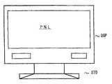
도 9는, 본 발명의 액정 표시 장치로서 액정 표시 모듈을 실장한 전자 기기의 일례인 텔레비전 수상기의 외관도이다. 도 9에서, 이 텔레비전 수상기는 표시부 DSP와 스탠드부 STD로 구성되며, 비교적 큰 사이즈의 화면을 갖는 액정 표시 패널 PNL을 갖는 액정 표시 장치가 표시부 DSP에 실장된다. 액정 표시 장치의 화면으로 되는 액정 표시 패널 PNL의 유효 표시 영역은 표시부 DSP에 노출되어 있다. 이 텔레비전 수상기의 표시부 DSP에 본 발명에 따른 고휘도의 면광원이 얻어지는 백 라이트 장치를 실장함으로써, 고휘도 및 고품위의 표시 화상이 얻어지는 액정 표시 장치를 실현할 수 있다.9 is an external view of a television receiver which is an example of an electronic apparatus in which a liquid crystal display module is mounted as the liquid crystal display device of the present invention. In Fig. 9, this television receiver is composed of a display unit DSP and a stand unit STD, and a liquid crystal display device having a liquid crystal display panel PNL having a relatively large size screen is mounted on the display unit DSP. The effective display area of the liquid crystal display panel PNL serving as the screen of the liquid crystal display device is exposed to the display unit DSP. By mounting the backlight device in which the high brightness surface light source according to the present invention is provided on the display unit DSP of the television receiver, a liquid crystal display device in which a high brightness and high quality display image is obtained can be realized.
또한, 전술한 실시예에서, 냉음극 형광 램프 직하형 백 라이트 장치를, 액정 표시 패널을 실장한 액정 텔레비전 수상기에 적용한 경우에 대하여 설명하였는데, 상기 구성에 의한 백 라이트 장치를 이용한 대형 액정 모니터, 차량 탑재용 액정 디스플레이(액정 카 내비게이션), 게임기용 액정 디스플레이, 의료용 액정 모니터, 인쇄/디자인용 액정 모니터 등의 표시 장치에 적용하여도 전술한 바와 마찬가지의 효과가 얻어진다.In addition, in the above-described embodiment, the case where the cold cathode fluorescent lamp direct type backlight device is applied to a liquid crystal television receiver mounted with a liquid crystal display panel has been described, but a large liquid crystal monitor and a vehicle using the backlight device according to the above configuration are described. The same effects as described above are also obtained when applied to display devices such as a liquid crystal display for mounting (liquid crystal car navigation), a liquid crystal display for game machines, a medical liquid crystal monitor, a liquid crystal monitor for printing / design, and the like.
본 발명에 따른 백 라이트 장치에 따르면, 복수의 선 형상 광원으로부터 방사된 광이 반사체에 의해 반사되므로, 광의 이용 효율이 높은 고휘도의 면 형상 광 원 광이 얻어진다는 매우 우수한 효과를 갖는다. 또한, 원하는 휘도를 얻는 경우에는, 선 형상 광원의 수량을 저감시키는 것이 가능해지며, 이것에 의해 저가화로 고휘도 발광의 백 라이트 장치가 실현 가능해진다는 매우 우수한 효과가 얻어진다.According to the backlight device according to the present invention, since the light emitted from the plurality of linear light sources is reflected by the reflector, it has a very excellent effect that high luminance planar light source light with high light utilization efficiency is obtained. In addition, when the desired luminance is obtained, it is possible to reduce the number of linear light sources, thereby obtaining a very excellent effect that the backlight device of high luminance emission can be realized at a low cost.
또한, 본 발명에 따른 액정 표시 장치에 따르면, 액정 표시 패널의 배면에 백 라이트 장치로부터 고휘도의 면 형상 광원 광이 조사되므로, 고휘도로 그와 같이 고품위의 화상 표시가 저가로 실현 가능하게 되는 등의 매우 우수한 효과가 얻어진다.In addition, according to the liquid crystal display device according to the present invention, since a high brightness planar light source light is irradiated to the back surface of the liquid crystal display panel, such high quality image display can be realized with high brightness at low cost. Very good effects are obtained.
Claims (20)
Translated fromKoreanApplications Claiming Priority (4)
| Application Number | Priority Date | Filing Date | Title |
|---|---|---|---|
| JPJP-P-2004-00275175 | 2004-09-22 | ||
| JP2004275175 | 2004-09-22 | ||
| JP2005231888AJP4125746B2 (en) | 2004-09-22 | 2005-08-10 | Backlight device and liquid crystal display device |
| JPJP-P-2005-00231888 | 2005-08-10 |
Publications (2)
| Publication Number | Publication Date |
|---|---|
| KR20060051519A KR20060051519A (en) | 2006-05-19 |
| KR100764411B1true KR100764411B1 (en) | 2007-10-05 |
Family
ID=36537487
Family Applications (1)
| Application Number | Title | Priority Date | Filing Date |
|---|---|---|---|
| KR1020050088035AExpired - Fee RelatedKR100764411B1 (en) | 2004-09-22 | 2005-09-22 | Backlight device and liquid crystal display device |
Country Status (3)
| Country | Link |
|---|---|
| JP (1) | JP4125746B2 (en) |
| KR (1) | KR100764411B1 (en) |
| TW (1) | TW200622439A (en) |
Families Citing this family (4)
| Publication number | Priority date | Publication date | Assignee | Title |
|---|---|---|---|---|
| KR20080018726A (en) | 2006-08-25 | 2008-02-28 | 엘지이노텍 주식회사 | Liquid crystal display |
| CN107166254B (en)* | 2017-07-05 | 2024-03-26 | 合肥惠科金扬科技有限公司 | Backlight module and display |
| CN110456572A (en)* | 2019-08-28 | 2019-11-15 | 合肥京东方光电科技有限公司 | A lamp panel and its preparation method, backlight module and liquid crystal display device |
| CN111308783A (en)* | 2020-03-25 | 2020-06-19 | 深圳市隆利科技股份有限公司 | LED backlight device and display equipment |
Citations (6)
| Publication number | Priority date | Publication date | Assignee | Title |
|---|---|---|---|---|
| JPH0675216A (en)* | 1992-08-27 | 1994-03-18 | Hitachi Ltd | Liquid crystal display |
| JPH06201904A (en)* | 1992-12-25 | 1994-07-22 | Dainippon Printing Co Ltd | Lenticular lens, surface light source and liquid crystal display device |
| KR20010043054A (en)* | 1998-04-30 | 2001-05-25 | 나카노 가츠히코 | Light guide plate |
| JP2001318614A (en)* | 2000-05-09 | 2001-11-16 | Mitsubishi Electric Corp | Surface light source device and liquid crystal display device using the same |
| JP2002082626A (en)* | 2000-09-08 | 2002-03-22 | Sharp Corp | Backlight device for display panel |
| KR20020084132A (en)* | 2000-12-14 | 2002-11-04 | 미쯔이카가쿠 가부시기가이샤 | Reflector, sidelight type backlighting apparatus and reflector substrate |
- 2005
- 2005-08-10JPJP2005231888Apatent/JP4125746B2/ennot_activeExpired - Fee Related
- 2005-09-19TWTW094132367Apatent/TW200622439A/ennot_activeIP Right Cessation
- 2005-09-22KRKR1020050088035Apatent/KR100764411B1/ennot_activeExpired - Fee Related
Patent Citations (6)
| Publication number | Priority date | Publication date | Assignee | Title |
|---|---|---|---|---|
| JPH0675216A (en)* | 1992-08-27 | 1994-03-18 | Hitachi Ltd | Liquid crystal display |
| JPH06201904A (en)* | 1992-12-25 | 1994-07-22 | Dainippon Printing Co Ltd | Lenticular lens, surface light source and liquid crystal display device |
| KR20010043054A (en)* | 1998-04-30 | 2001-05-25 | 나카노 가츠히코 | Light guide plate |
| JP2001318614A (en)* | 2000-05-09 | 2001-11-16 | Mitsubishi Electric Corp | Surface light source device and liquid crystal display device using the same |
| JP2002082626A (en)* | 2000-09-08 | 2002-03-22 | Sharp Corp | Backlight device for display panel |
| KR20020084132A (en)* | 2000-12-14 | 2002-11-04 | 미쯔이카가쿠 가부시기가이샤 | Reflector, sidelight type backlighting apparatus and reflector substrate |
Also Published As
| Publication number | Publication date |
|---|---|
| JP4125746B2 (en) | 2008-07-30 |
| TWI311223B (en) | 2009-06-21 |
| KR20060051519A (en) | 2006-05-19 |
| TW200622439A (en) | 2006-07-01 |
| JP2006119600A (en) | 2006-05-11 |
Similar Documents
| Publication | Publication Date | Title |
|---|---|---|
| US7237939B2 (en) | Backlight assembly and liquid crystal display apparatus using the same | |
| CN100543548C (en) | Surface light source device and image display device using same | |
| US7883232B2 (en) | Light-emitting diode backlight assembly and liquid crystal display device using the same | |
| US8246187B2 (en) | Display device using diffusive light guide plate | |
| US20070147088A1 (en) | Backlight module with dual light guide plates and liquid crystal display with same | |
| US7360942B2 (en) | Receiving container for a display apparatus, backlight assembly and display apparatus having the receiving container, and method thereof | |
| EP2458430A1 (en) | Backlight unit and display apparatus using the same | |
| US10809554B2 (en) | Display apparatus | |
| WO2011065052A1 (en) | Planar lighting device and display device having same | |
| KR100844763B1 (en) | Backlight Unit of Liquid Crystal Display | |
| KR20040081001A (en) | Liquid crystal display module | |
| GB2423622A (en) | Light-emitting-diode backlight assembly and liquid crystal display device using the same | |
| TWI403802B (en) | Backlight assembly provided with an improved light guiding plate and a display device provided with the same | |
| US7102162B2 (en) | Plane light source structure for planar display | |
| KR20050105568A (en) | Lcd and the backlight unit thereof | |
| CN111752043A (en) | Backlight module and display device | |
| CN100565294C (en) | Backlight assembly and have the display device of this backlight assembly | |
| KR100764411B1 (en) | Backlight device and liquid crystal display device | |
| US20080112190A1 (en) | Light guide plate having recessed region(s) disposed thereon | |
| JP3571190B2 (en) | Illumination device and reflection type liquid crystal display device having the same | |
| KR102002458B1 (en) | Liquid crystal display device | |
| US20070177403A1 (en) | Prism of backlight module and structure thereof | |
| JPH11249134A (en) | Lighting device, liquid crystal device and electronic equipment | |
| KR20070002876A (en) | LCD Display Module | |
| KR100885845B1 (en) | Transflective Liquid Crystal Display Device |
Legal Events
| Date | Code | Title | Description |
|---|---|---|---|
| PA0109 | Patent application | St.27 status event code:A-0-1-A10-A12-nap-PA0109 | |
| R18-X000 | Changes to party contact information recorded | St.27 status event code:A-3-3-R10-R18-oth-X000 | |
| A201 | Request for examination | ||
| PA0201 | Request for examination | St.27 status event code:A-1-2-D10-D11-exm-PA0201 | |
| PN2301 | Change of applicant | St.27 status event code:A-3-3-R10-R13-asn-PN2301 St.27 status event code:A-3-3-R10-R11-asn-PN2301 | |
| PG1501 | Laying open of application | St.27 status event code:A-1-1-Q10-Q12-nap-PG1501 | |
| E902 | Notification of reason for refusal | ||
| PE0902 | Notice of grounds for rejection | St.27 status event code:A-1-2-D10-D21-exm-PE0902 | |
| E13-X000 | Pre-grant limitation requested | St.27 status event code:A-2-3-E10-E13-lim-X000 | |
| P11-X000 | Amendment of application requested | St.27 status event code:A-2-2-P10-P11-nap-X000 | |
| P13-X000 | Application amended | St.27 status event code:A-2-2-P10-P13-nap-X000 | |
| E701 | Decision to grant or registration of patent right | ||
| PE0701 | Decision of registration | St.27 status event code:A-1-2-D10-D22-exm-PE0701 | |
| GRNT | Written decision to grant | ||
| PR0701 | Registration of establishment | St.27 status event code:A-2-4-F10-F11-exm-PR0701 | |
| PR1002 | Payment of registration fee | St.27 status event code:A-2-2-U10-U11-oth-PR1002 Fee payment year number:1 | |
| PG1601 | Publication of registration | St.27 status event code:A-4-4-Q10-Q13-nap-PG1601 | |
| G170 | Re-publication after modification of scope of protection [patent] | ||
| PG1701 | Publication of correction | St.27 status event code:A-5-5-P10-P19-oth-PG1701 Patent document republication publication date:20080416 Republication note text:Request for Correction Notice (Document Request) Gazette number:1007644110000 Gazette reference publication date:20071005 | |
| R17-X000 | Change to representative recorded | St.27 status event code:A-5-5-R10-R17-oth-X000 | |
| FPAY | Annual fee payment | Payment date:20100614 Year of fee payment:4 | |
| PR1001 | Payment of annual fee | St.27 status event code:A-4-4-U10-U11-oth-PR1001 Fee payment year number:4 | |
| LAPS | Lapse due to unpaid annual fee | ||
| PC1903 | Unpaid annual fee | St.27 status event code:A-4-4-U10-U13-oth-PC1903 Not in force date:20110929 Payment event data comment text:Termination Category : DEFAULT_OF_REGISTRATION_FEE | |
| PC1903 | Unpaid annual fee | St.27 status event code:N-4-6-H10-H13-oth-PC1903 Ip right cessation event data comment text:Termination Category : DEFAULT_OF_REGISTRATION_FEE Not in force date:20110929 | |
| P22-X000 | Classification modified | St.27 status event code:A-4-4-P10-P22-nap-X000 |