KR100759129B1 - Socket for indoor electricity supply in public housing - Google Patents
Socket for indoor electricity supply in public housingDownload PDFInfo
- Publication number
- KR100759129B1 KR100759129B1KR1020070020281AKR20070020281AKR100759129B1KR 100759129 B1KR100759129 B1KR 100759129B1KR 1020070020281 AKR1020070020281 AKR 1020070020281AKR 20070020281 AKR20070020281 AKR 20070020281AKR 100759129 B1KR100759129 B1KR 100759129B1
- Authority
- KR
- South Korea
- Prior art keywords
- case
- insertion groove
- outlet
- protrusion
- fixed
- Prior art date
- Legal status (The legal status is an assumption and is not a legal conclusion. Google has not performed a legal analysis and makes no representation as to the accuracy of the status listed.)
- Expired - Fee Related
Links
Images


Classifications
- H—ELECTRICITY
- H01—ELECTRIC ELEMENTS
- H01R—ELECTRICALLY-CONDUCTIVE CONNECTIONS; STRUCTURAL ASSOCIATIONS OF A PLURALITY OF MUTUALLY-INSULATED ELECTRICAL CONNECTING ELEMENTS; COUPLING DEVICES; CURRENT COLLECTORS
- H01R13/00—Details of coupling devices of the kinds covered by groups H01R12/70 or H01R24/00 - H01R33/00
- H01R13/44—Means for preventing access to live contacts
- H01R13/447—Shutter or cover plate
- H—ELECTRICITY
- H01—ELECTRIC ELEMENTS
- H01R—ELECTRICALLY-CONDUCTIVE CONNECTIONS; STRUCTURAL ASSOCIATIONS OF A PLURALITY OF MUTUALLY-INSULATED ELECTRICAL CONNECTING ELEMENTS; COUPLING DEVICES; CURRENT COLLECTORS
- H01R13/00—Details of coupling devices of the kinds covered by groups H01R12/70 or H01R24/00 - H01R33/00
- H01R13/02—Contact members
- H01R13/10—Sockets for co-operation with pins or blades
- H—ELECTRICITY
- H01—ELECTRIC ELEMENTS
- H01R—ELECTRICALLY-CONDUCTIVE CONNECTIONS; STRUCTURAL ASSOCIATIONS OF A PLURALITY OF MUTUALLY-INSULATED ELECTRICAL CONNECTING ELEMENTS; COUPLING DEVICES; CURRENT COLLECTORS
- H01R13/00—Details of coupling devices of the kinds covered by groups H01R12/70 or H01R24/00 - H01R33/00
- H01R13/66—Structural association with built-in electrical component
- H01R13/70—Structural association with built-in electrical component with built-in switch
- H—ELECTRICITY
- H01—ELECTRIC ELEMENTS
- H01R—ELECTRICALLY-CONDUCTIVE CONNECTIONS; STRUCTURAL ASSOCIATIONS OF A PLURALITY OF MUTUALLY-INSULATED ELECTRICAL CONNECTING ELEMENTS; COUPLING DEVICES; CURRENT COLLECTORS
- H01R13/00—Details of coupling devices of the kinds covered by groups H01R12/70 or H01R24/00 - H01R33/00
- H01R13/66—Structural association with built-in electrical component
- H01R13/717—Structural association with built-in electrical component with built-in light source
- H—ELECTRICITY
- H01—ELECTRIC ELEMENTS
- H01R—ELECTRICALLY-CONDUCTIVE CONNECTIONS; STRUCTURAL ASSOCIATIONS OF A PLURALITY OF MUTUALLY-INSULATED ELECTRICAL CONNECTING ELEMENTS; COUPLING DEVICES; CURRENT COLLECTORS
- H01R13/00—Details of coupling devices of the kinds covered by groups H01R12/70 or H01R24/00 - H01R33/00
- H01R13/73—Means for mounting coupling parts to apparatus or structures, e.g. to a wall
Landscapes
- Details Of Connecting Devices For Male And Female Coupling (AREA)
- Connector Housings Or Holding Contact Members (AREA)
Abstract
Translated fromKoreanDescription
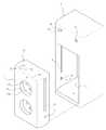
Translated fromKorean도 1은 본 발명에 따른 실내전기공급용 소켓의 분해사시도이고,1 is an exploded perspective view of a socket for indoor electricity supply according to the present invention;
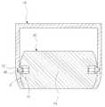
도 2는 본 발명에 따른 실내전기공급용 소켓의 부분 측단면도이고,2 is a partial side cross-sectional view of a socket for indoor electricity supply according to the present invention;
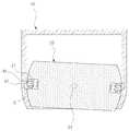
도 3 및 도 4는 본 발명에 따른 실내전기공급용 소켓의 평단면도이고,3 and 4 is a plan sectional view of a socket for indoor electricity supply according to the present invention,
도 5 내지 도 7은 본 발명에 따른 실내전기공급용 소켓의 작동상태를 나타낸 단면도이다.5 to 7 are cross-sectional views showing the operating state of the socket for indoor electricity supply according to the present invention.
-첨부도면의 주요부분에 대한 용어설명-Explanation of terms for main parts of attached drawings
10 ; 케이스 11 ; 수용부10; Case 11; Receptacle
12 ; 정지기구삽입홈 13 ; 가이드홀 14 ; 제1돌부삽입홀 14` ; 제2돌부삽입홀12;
20 ; 콘센트 21 ; 가이드부 22, 22` ; 고정홈 23 ; 회전축20;
24 ; 플러그연결홈 30 ; 고정기구 31 ; 모터 32 ; 스토퍼 33 ; 볼트 34 ; 너트24; Plug connection groove 30;
40 ; 정지기구 50 ; 스위치40;
60 ; 발광수단 61 ; 버튼 62 ; 램프 P ; 돌부 B ; 본체 S ; 스프링60; Light emitting means 61;
본 발명은 공공주택의 실내전기공급용 소켓에 관한 것이다.The present invention relates to a socket for indoor electricity supply of public housing.
일반적으로 콘센트는 건물의 바닥면이나 벽면에 설치되는 매립형 콘센트와, 가정이나 일반 사무실에 구비된 콘센트에 연결되어 다른 전기제품이 사용될 수 있도록 하는 멀티콘센트등이 여러가지 구조로 개발되어 사용되고 있다.In general, the outlet is a land-filled outlet installed on the floor or wall of the building, and a multi-outlet that is connected to the outlet provided in the home or general office so that other electrical appliances can be used in a variety of structures.
이러한 종래의 콘센트는 플러그가 꼽히는 플러그연결홈이 외부로 노출되어 있어서, 도전체가 플러그연결홈에 삽입될 수 있으며, 이로 인해 감전사고가 발생할 가능성이 높다. 특히 유아들은 사고능력과 판단능력이 부족하기 때문에 보호자의 관심이 소홀할 시 도전체를 콘센트의 플러그연결홈에 삽입시킬 수 있어, 그 위험 정도가 더 크다 할 수 있다.In such a conventional outlet, the plug connection groove into which the plug is inserted is exposed to the outside, so that a conductor may be inserted into the plug connection groove, which may cause an electric shock accident. In particular, infants lack the ability to think and judge, so when the caregiver's attention is neglected, the conductor can be inserted into the plug's groove of the outlet, which may be more dangerous.
또한 콘센트가 항상 외부로 노출되어 있으므로 먼지 등의 이물질이 콘센트의 플러그연결홈에 묻기 쉬워, 이로 인해 전기제품을 사용시 스파크가 이물질에 튀어 화재가 발생할 수 있을 뿐만 아니라, 물리적 손상을 입기도 쉽다.In addition, since the outlet is always exposed to the outside, foreign matters such as dust are easily attached to the plug connection groove of the outlet, which can cause sparks to splash on the foreign materials and cause physical damage as well.
이에 본 발명은 상기와 같은 문제를 해소하기 위해 발명된 것으로, 플러그 연결홈으로의 이물질 삽입으로 인한 콘센트 손상과 감전사고를 효과적으로 방지하며, 주변환경이 어두운 상태에서도 콘센트의 위치 확인이 용이한 공공주택의 실내전기공급용 소켓을 제공함에 그 목적이 있다.Accordingly, the present invention has been invented to solve the above problems, effectively prevent the outlet damage and electric shock caused by the insertion of foreign matter into the plug connection groove, public housing easy to check the location of the outlet even in a dark environment The purpose is to provide a socket for indoor electrical supply of.
상기와 같은 목적을 달성하기 위한 본 발명은, 전면이 개구된 수용부와, 수용부의 상면에 형성된 가이드홀과 수용부 내부 양측면에 상호 대칭되게 형성되는 제1돌부삽입홈 및 제2돌부삽입홈를 갖추고서 벽체에 매설되는 케이스와 ; 전면에 형성되는 플러그연결홈을 갖추고서 수직방향의 회전축을 매개로 케이스의 수용부에 회전가능하게 내설되되, 상면 또는 저면에 회전축을 중심으로 이의 좌우측에 대칭되게 형성되는 한 쌍의 고정홈이 구비되며 제1돌부삽입홈 및 제2돌부삽입홈에 삽탈되는 탄성재질의 돌부가 양측면에 형성되는 본체와, 본체에 내설되어 플러그 본체에 삽입된 입력단자와 전기적으로 연결되는 출력단자를 갖추고서, 케이스에 회전가능하게 고정되는 콘센트 ; 케이스에 설치되는 모터와, 모터의 출력축에 고정되는 볼트, 볼트에 나사산결합되어 직선왕복이동되는 너트, 너트에 고정연결되어 콘센트 본체의 고정홈에 삽탈되는 스토퍼를 갖춘 고정기구 ; 케이스에 설치되어 모터의 전력공급을 제어하는 스위치 및 ; 케이스의 전면에 설치되는 램프와, 케이스의 제1 돌부삽입홈에 설치되며 돌부에 의해 ON·OFF 되어 램프로의 전력공급을 제어하는 버튼을 갖춘 발광수단으로 이루어진다.The present invention for achieving the above object is provided with a receiving portion having a front opening, a first hole insertion groove and a second protrusion insertion groove which are formed symmetrically on both sides of the guide hole formed on the upper surface of the receiving portion and the receiving portion. A case embedded in the wall; It has a plug connection groove formed on the front side and is rotatably installed in the housing of the case via a vertical axis of rotation, and has a pair of fixing grooves symmetrically formed on the left and right sides of the rotary axis on the top or bottom thereof. And a main body having elastic protrusions inserted into the first protrusion insertion groove and the second protrusion insertion groove formed on both sides thereof, and an output terminal electrically connected to the input terminal embedded in the main body and inserted into the plug body. An outlet rotatably fixed to the outlet; A fixing mechanism having a motor installed in the case, a bolt fixed to the output shaft of the motor, a nut threadedly coupled to the bolt to be reciprocated linearly, and a stopper fixedly connected to the nut and inserted into the fixing groove of the outlet body; A switch installed in the case and controlling the power supply of the motor; And a light emitting means having a lamp installed at the front of the case, and a button installed in the first protrusion insertion groove of the case, the button being turned on and off by the protrusion to control power supply to the lamp.
이하 첨부된 예시도면에 의거하여 상세히 설명한다.Hereinafter will be described in detail with reference to the accompanying drawings.
도 1은 본 발명에 따른 실내전기공급용 소켓의 분해사시도이고, 도 2는 본 발명에 따른 실내전기공급용 소켓의 부분 측단면도이고, 도 3 및 도 4는 본 발명에 따른 실내전기공급용 소켓의 평단면도로서, 도 1 내지 도 4를 참조하면 다음과 같다.1 is an exploded perspective view of a socket for an indoor electricity supply according to the present invention, Figure 2 is a partial side cross-sectional view of a socket for an indoor electricity supply according to the present invention, Figures 3 and 4 is a socket for an indoor electricity supply according to the present invention As a plan cross-sectional view of Figures 1 to 4 as follows.
실내전기공급용 소켓은, 전면이 개구된 수용부(11)와, 수용부(11)의 상면에 형성된 가이드홀(13)과 수용부(11) 내부 양측면에 상호 대칭되게 형성되는 제1돌부삽입홈(14) 및 제2돌부삽입홈(14`)를 갖추고서 벽체에 매설되는 케이스(10)와 ; 전면에 형성되는 플러그연결홈(24)을 갖추고서 수직방향의 회전축(23)을 매개로 케이스(10)의 수용부(11)에 회전가능하게 내설되되, 상면 또는 저면에 회전축(23)을 중심으로 이의 좌우측에 대칭되게 형성되는 한 쌍의 고정홈(22,22`)이 구비되며 제1돌부삽입홈(14) 및 제2돌부삽입홈(14`)에 삽탈되는 탄성재질의 돌부(P)가 양측면에 형성되는 본체(B)와, 본체(B)에 내설되어 플러그 본체에 삽입된 입력단자와 전기적으로 연결되는 출력단자를 갖추고서, 케이스(10)에 회전가능하게 고정되는 콘센트(20) ; 케이스(10)에 설치되는 모터(31)와, 모터(31)의 출력축에 고정되는 볼트(33), 볼트(33)에 나사산결합되어 직선왕복이동되는 너트(34), 너트(34)에 고정연결되어 콘센트 본체(B)의 고정홈(22,22`)에 삽탈되는 스토퍼(32)를 갖춘 고정기 구(30) ; 케이스(10)에 설치되어 모터(31)의 전력공급을 제어하는 스위치(50) 및 ; 케이스(10)의 전면에 설치되는 램프(62)와, 케이스(10)의 제1돌부삽입홈(14)에 설치되며 돌부(P)에 의해 ON·OFF 되어 램프(62)로의 전력공급을 제어하는 버튼(61)을 갖춘 발광수단(60)로 이루어진다.The indoor electricity supply socket has a receiving portion 11 having an open front surface, a first protrusion insertion formed symmetrically on both sides of the
더 바람직하게는 상기 케이스(10)의 내부 측면에 정지기구삽입홈(12)이 구비되는 한편, 콘센트 본체(B)의 외면이 라운드 처리되고, 이 라운드 처리된 콘센트 본체(B)의 측면에 가이드부(21)가 형성되어, 케이스(10)의 정지기구삽입홈(12)에 삽탈되는 정지기구(40)가 가이드부(21)에 수평방향으로 직선왕복이동가능하게 고정되어 스프링(S)을 매개로 일방향으로 탄발지지된다.More preferably, the stop
상기 케이스(10)는, 장방형 형상으로 전면에 수용부(11)가 형성되되 수용부(11)의 양측면이 라운드 져지며, 수용부(11)의 내부 양측면에 정지기구삽입홈(12)이 수직방향으로 형성되고, 수용부(11)의 내부 상면에 가이드홀(13)이 형성되어, 벽체에 매설된다. 또한 케이스(10)의 수용부(11) 양측면으로는 상호대칭되게 형성되는 제1돌부삽입홈(14) 및 제2돌부삽입홈(14`)이 수용부(11)의 하부에 구비된다.The
상기 콘센트(20)는 플러그삽입홈(24a)과 단자삽입홈(24b)으로 이루어진 플러그연결홈(24)을 갖춘 본체(B)와, 본체(B)에 내설되어 플러그 본체에 삽입된 입력단자와 전기적으로 연결되는 출력단자를 갖추고서, 케이스(10)에 회전가능하게 고정된다.The
상기 본체(B)는 상면에 회전축(23)을 중심으로 좌우대칭되는 고정홈(22,22`) 이 형성되어, 회전축(23)을 매개로 케이스(10)에 회전가능하게 고정되며, 양측면에는 케이스(10)의 제1돌부삽입홈(14) 및 제2돌부삽입홈(14`)에 삽탈되는 돌부(P)가 형성된다. 이때 돌부(P)는 신축성이 좋은 탄성재질을 이용한다. 또한 외면이 라운드 처리되고, 이 라운드 처리된 콘센트 본체(B)의 측면에 가이드부(21)가 형성되어, 케이스(10)의 정지기구삽입홈(12)에 삽탈되는 정지기구(40)가 가이드부(21)에 수평방향으로 직선왕복이동가능하게 고정되어 스프링(S)을 매개로 일방향으로 탄발지지된다. 한편, 콘센트(20)의 전력라인은 회전축(23)을 통해 외부로 연결된다.The main body B has fixing
상기 고정기구(30)는 케이스(10)의 상부 내부에 형성된 공간부(A)에 고정되는 모터(31)와, 모터(31)의 회전축에 회전가능하게 고정되는 볼트(33)와, 볼트(33)와 나사체결되는 너트(34)와, 연결구(R)를 매개로 너트(33)와 연결되는 스토퍼(32)로 이루어진다.The fixing mechanism 30 includes a
상기 모터(31)는 모터(31)의 출력축이 회전하도록 회전력을 제공하여 모터(31)의 출력축에 고정된 볼트(33)를 회전시키고, 너트(34)는 회전하는 볼트(33)를 따라 직선운동한다. 이때 너트(34)는 연결구(R)를 매개로 스토퍼(32)와 회전하지 않게 고정되므로, 너트(34)의 직선운동은 연결구(R)를 통해 스토퍼(32)로 전달되어, 결국에는 볼트(33)의 회전운동이 스토퍼(32)의 직선운동으로 변환된다. 한편, 스토퍼(32)는 케이스(10)의 가이드홀(13)의 안내를 받으면서 콘센트 본체(B)의 고정홈(22,22`)에 삽탈된다.The
상기 정지기구(40)는 콘센트(20)의 가이드부(21)에 수평방향으로 직선왕복이동가능하게 고정되어 스프링(S)을 매개로 일방향으로 탄발지지되어, 케이스(10)의 정지기구삽입홈(12)에 삽탈되도록 왕복이동한다.The
상기 스위치(50)은 케이스(10)의 외면 상면에 설치되어 모터(31)로의 전력공급을 제어한다.The
상기 발광수단(60)은 케이스 수용부(11)의 제1돌부삽입홈(14)에 설치되는 버튼(61)과, 케이스(10)의 전면 상부에 설치되어 버튼(61)과 전기적으로 연결되는 램프(62)로 구성되며, 버튼(61)은 외부 힘에 의해 눌려질 때는 전력을 공급하며, 외부 힘이 사라졌을 때는 원위치로 복귀하여 전력공급을 차단하는 통상적인 푸쉬스위치이다.The light emitting means 60 is a
도 5 내지 도 7은 본 발명에 따른 실내전기공급용 소켓의 작동상태를 나타낸 단면도로서, 도 5 내지 도 7을 참조하여 본 발명에 따른 실내전기공급용 소켓의 작동상태를 살펴보면 다음과 같다.5 to 7 are cross-sectional views showing the operating state of the indoor electricity supply socket according to the present invention. Referring to FIGS. 5 to 7, the operation state of the indoor electricity supply socket according to the present invention will be described below.
우선, 스위치(50)을 누르면, 스위치(50)와 전기적으로 연결된 모터(31)가 회전을 하고, 이와 더불어 볼트(33)가 회전을 한다. 볼트(33)와 나사체결된 너트(34)는 볼트(33)의 회전으로 인해 상방향으로 이동을 하고, 연결구(R)를 매개로 너트(33)와 연결된 스토퍼(32)가 콘센트(20)의 고정홈(22)로부터 빠져나와 도 5와 같이 된다.First, when the
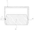
이후, 콘센트(20)을 뒤로 밀면, 콘센트(20)는 회전축(23)를 중심으로 회전을 하려하고, 정지기구(40)는 도 6과 같이 스프링(S)을 압축시키면서 가이드부(21) 내부로 이동한다. 케이스(10)의 정지기구삽입홈(12)을 빠져나온 콘센트(20)는 계속적으로 회전하게 되고, 케이스(10)의 정지기구삽입홈(12)을 빠져나온 정지기구(40)가 스프링(S)의 복원력에 의해 원래의 위치로 복귀한다. 이때 콘센트 본체(B)의 측면에 구비된 돌부(P) 또한 케이스(10)의 제2돌부삽입홈(14`)로부터 이탈하여 도 7과 같이 된다.Thereafter, when the
이후 계속적인 회전력을 받은 콘센트(20)는 정지기구(40)가 정지기구삽입홈(12)에 삽입되어 케이스(10)에 고정되고, 콘센트(20)의 방향은 처음과 반대의 위치가 된다. 이때 콘센트 본체(B)의 돌부(P)는 케이스(10)의 제1돌부삽입홈(14)에 삽입되며, 이와 동시에 발광수단(60)의 버튼(61)을 눌러 외부 전원으로부터 램프(62)로 전력을 공급하여, 램프(62)가 점등되도록 한다.Since the
상기와 같이 콘센트(20)의 위치가 반대로 되면 스위치(50)을 눌러, 고정기구(30)의 모터(31)가 역방향으로 돌아, 너트(34)가 하방향으로 이동하게 되고, 스토퍼(32)가 콘센트(20)의 고정홈(22`)에 삽입고정되어, 콘센트(20)가 케이스(10)에 고정되게 한다.When the position of the
한편, 콘센트(20)을 다시 사용할 필요가 있을 시는 콘센트(20)를 역방향으로 돌려, 콘센트(20)를 사용위치로 복귀시킨다.On the other hand, when the
이러한 실내전기공급용 소켓은 콘센트(20)를 사용하지 않을 시에는 플러그가 꼽히는 콘센트(20)의 플러그연결홈를 외부로 노출시키지 않음으로써, 부주위로 인한 감전사고를 예방할 수 있다. 특히 사고능력과 판단능력이 부족한 유아들의 콘센트(20) 감전사고를 방지할 수 있다.Such a socket for indoor electricity supply does not expose the plug connection groove of the
또한, 먼지 등의 이물질이 콘센트의 플러그연결홈에 묻게 하지 않아, 전기 제품 사용시 발생할 수 있는 스파크에 의한 화재를 방지할 뿐만 아니라, 외부 노출로 인한 물리적 손상도 입지 않는다.In addition, the foreign matter such as dust does not get in the plug connection groove of the outlet, not only to prevent the fire caused by sparks that may occur when using electrical appliances, but also does not suffer physical damage due to external exposure.
게다가 외관미 또한 향상되고, 어두운 곳에서도 콘센트(20)의 사용상태를 쉽게 구별할 수 있어 사용의 편이성이 제공된다.In addition, the appearance is also improved, and even in a dark place, the state of use of the
본 발명은 상기한 바와 같은 실시예에 한정되지 않고 이하 청구범위를 벗어나지 않는 한도 내에서 보다 다양하게 변형실시될 수 있음은 물론이다.The present invention is not limited to the embodiment as described above, but may be modified in various ways within the scope of the claims below.
이상 상기한 바와 같은 본 발명에 따르면, 케이스(10)와 ; 케이스(10)에 회전가능하게 설치되는 콘센트(20) ; 케이스(10)에 설치되는 고정기구(30) 및 고정기구(30)로의 전력공급을 제어하는 스위치(50) 및 ; 콘센트(20)의 사용상태를 나타내는 발광수단(60)으로 이루어져, 플러그연결홈의 이물질 삽입으로 인한 콘센트 손상과 감전사고를 효과적으로 방지할 수 있으며, 외관미 또한 향상되고, 주변환경이 어두운 상태에서도 콘센트(20)의 위치를 쉽게 구별할 수 있는 효과가 있다.According to the present invention as described above, the
Claims (2)
Translated fromKoreanPriority Applications (1)
| Application Number | Priority Date | Filing Date | Title |
|---|---|---|---|
| KR1020070020281AKR100759129B1 (en) | 2007-02-28 | 2007-02-28 | Socket for indoor electricity supply in public housing |
Applications Claiming Priority (1)
| Application Number | Priority Date | Filing Date | Title |
|---|---|---|---|
| KR1020070020281AKR100759129B1 (en) | 2007-02-28 | 2007-02-28 | Socket for indoor electricity supply in public housing |
Publications (1)
| Publication Number | Publication Date |
|---|---|
| KR100759129B1true KR100759129B1 (en) | 2007-09-20 |
Family
ID=38738005
Family Applications (1)
| Application Number | Title | Priority Date | Filing Date |
|---|---|---|---|
| KR1020070020281AExpired - Fee RelatedKR100759129B1 (en) | 2007-02-28 | 2007-02-28 | Socket for indoor electricity supply in public housing |
Country Status (1)
| Country | Link |
|---|---|
| KR (1) | KR100759129B1 (en) |
Cited By (5)
| Publication number | Priority date | Publication date | Assignee | Title |
|---|---|---|---|---|
| KR100861589B1 (en) | 2008-04-10 | 2008-10-07 | 주식회사 나우기술단 | Fixed socket for light installation in apartment house |
| CN104953345A (en)* | 2015-07-02 | 2015-09-30 | 陈波 | Multifunctional wall switch |
| CN113224579A (en)* | 2021-05-10 | 2021-08-06 | 中山市佰源凯照明电器有限公司 | Intelligent socket with flame retardant function |
| KR102483167B1 (en)* | 2022-03-23 | 2023-01-04 | (주)한승이엔씨 | Method of providing socket device for electricity supply in apartment houses and indoor buildings |
| KR102483168B1 (en)* | 2022-03-23 | 2023-01-04 | (주)한승이엔씨 | Method of providing connecting socket device for base station connection line |
Citations (2)
| Publication number | Priority date | Publication date | Assignee | Title |
|---|---|---|---|---|
| KR20020000846A (en)* | 2000-06-28 | 2002-01-05 | 제이 엘. 차스킨, 버나드 스나이더, 아더엠. 킹 | Cvd titanium-boron and chromium-boron coating of diamond |
| KR100633372B1 (en)* | 2006-09-15 | 2006-10-16 | 주식회사 세종전력기술단 | Wall outlet box |
- 2007
- 2007-02-28KRKR1020070020281Apatent/KR100759129B1/ennot_activeExpired - Fee Related
Patent Citations (2)
| Publication number | Priority date | Publication date | Assignee | Title |
|---|---|---|---|---|
| KR20020000846A (en)* | 2000-06-28 | 2002-01-05 | 제이 엘. 차스킨, 버나드 스나이더, 아더엠. 킹 | Cvd titanium-boron and chromium-boron coating of diamond |
| KR100633372B1 (en)* | 2006-09-15 | 2006-10-16 | 주식회사 세종전력기술단 | Wall outlet box |
Cited By (5)
| Publication number | Priority date | Publication date | Assignee | Title |
|---|---|---|---|---|
| KR100861589B1 (en) | 2008-04-10 | 2008-10-07 | 주식회사 나우기술단 | Fixed socket for light installation in apartment house |
| CN104953345A (en)* | 2015-07-02 | 2015-09-30 | 陈波 | Multifunctional wall switch |
| CN113224579A (en)* | 2021-05-10 | 2021-08-06 | 中山市佰源凯照明电器有限公司 | Intelligent socket with flame retardant function |
| KR102483167B1 (en)* | 2022-03-23 | 2023-01-04 | (주)한승이엔씨 | Method of providing socket device for electricity supply in apartment houses and indoor buildings |
| KR102483168B1 (en)* | 2022-03-23 | 2023-01-04 | (주)한승이엔씨 | Method of providing connecting socket device for base station connection line |
Similar Documents
| Publication | Publication Date | Title |
|---|---|---|
| KR100758689B1 (en) | Wall buried outlet terminal box of apartment house | |
| ES3024682T3 (en) | Passive rebound switch having variable number of buttons | |
| US7249976B1 (en) | Electrical plug, receptacle and switch | |
| CN107591645B (en) | Safety socket and its application | |
| KR100759129B1 (en) | Socket for indoor electricity supply in public housing | |
| US9196996B2 (en) | Safe outlet | |
| CN104380538A (en) | Safety socket and its application | |
| CN204289859U (en) | A kind of safety socket | |
| KR100758340B1 (en) | Terminal box for indoor electricity supply in apartment houses | |
| KR100758342B1 (en) | Electric outlet structure of electric shock prevention prevention apartment building | |
| KR101690219B1 (en) | Safety receptacle | |
| KR100759121B1 (en) | Electrical outlet terminal box for electric shock prevention | |
| KR100760697B1 (en) | Outlet structure installed in apartment house | |
| KR100759119B1 (en) | Electric shock prevention wiring terminal structure of apartment house | |
| CN105206973A (en) | Anti-electric-shock socket | |
| KR100759120B1 (en) | Outlet structure to prevent electric shock | |
| KR100760662B1 (en) | Buried type outlet structure of public house | |
| KR100739886B1 (en) | Indoor outlet box for electric shock prevention | |
| KR101249792B1 (en) | A power saving outleet which cut off standby power at standby mode | |
| KR102483167B1 (en) | Method of providing socket device for electricity supply in apartment houses and indoor buildings | |
| US8378971B2 (en) | Wireless mouse | |
| KR100768958B1 (en) | Electrical outlet box embedded in the interior wall of the apartment | |
| KR100758685B1 (en) | Safety type electricity supply terminal box of apartment | |
| US20090267789A1 (en) | Socket Structure with a Remote Control Switch | |
| KR102483168B1 (en) | Method of providing connecting socket device for base station connection line |
Legal Events
| Date | Code | Title | Description |
|---|---|---|---|
| A201 | Request for examination | ||
| PA0109 | Patent application | St.27 status event code:A-0-1-A10-A12-nap-PA0109 | |
| PA0201 | Request for examination | St.27 status event code:A-1-2-D10-D11-exm-PA0201 | |
| N231 | Notification of change of applicant | ||
| PN2301 | Change of applicant | St.27 status event code:A-3-3-R10-R13-asn-PN2301 St.27 status event code:A-3-3-R10-R11-asn-PN2301 | |
| A302 | Request for accelerated examination | ||
| PA0302 | Request for accelerated examination | St.27 status event code:A-1-2-D10-D17-exm-PA0302 St.27 status event code:A-1-2-D10-D16-exm-PA0302 | |
| E902 | Notification of reason for refusal | ||
| PE0902 | Notice of grounds for rejection | St.27 status event code:A-1-2-D10-D21-exm-PE0902 | |
| R18-X000 | Changes to party contact information recorded | St.27 status event code:A-3-3-R10-R18-oth-X000 | |
| P11-X000 | Amendment of application requested | St.27 status event code:A-2-2-P10-P11-nap-X000 | |
| P13-X000 | Application amended | St.27 status event code:A-2-2-P10-P13-nap-X000 | |
| E701 | Decision to grant or registration of patent right | ||
| PE0701 | Decision of registration | St.27 status event code:A-1-2-D10-D22-exm-PE0701 | |
| GRNT | Written decision to grant | ||
| N231 | Notification of change of applicant | ||
| PN2301 | Change of applicant | St.27 status event code:A-5-5-R10-R13-asn-PN2301 St.27 status event code:A-5-5-R10-R11-asn-PN2301 | |
| PR0701 | Registration of establishment | St.27 status event code:A-2-4-F10-F11-exm-PR0701 | |
| PR1002 | Payment of registration fee | St.27 status event code:A-2-2-U10-U11-oth-PR1002 Fee payment year number:1 | |
| PG1601 | Publication of registration | St.27 status event code:A-4-4-Q10-Q13-nap-PG1601 | |
| LAPS | Lapse due to unpaid annual fee | ||
| PC1903 | Unpaid annual fee | St.27 status event code:A-4-4-U10-U13-oth-PC1903 Not in force date:20100911 Payment event data comment text:Termination Category : DEFAULT_OF_REGISTRATION_FEE | |
| PC1903 | Unpaid annual fee | St.27 status event code:N-4-6-H10-H13-oth-PC1903 Ip right cessation event data comment text:Termination Category : DEFAULT_OF_REGISTRATION_FEE Not in force date:20100911 | |
| PN2301 | Change of applicant | St.27 status event code:A-5-5-R10-R13-asn-PN2301 St.27 status event code:A-5-5-R10-R11-asn-PN2301 | |
| PN2301 | Change of applicant | St.27 status event code:A-5-5-R10-R13-asn-PN2301 St.27 status event code:A-5-5-R10-R11-asn-PN2301 | |
| PN2301 | Change of applicant | St.27 status event code:A-5-5-R10-R13-asn-PN2301 St.27 status event code:A-5-5-R10-R11-asn-PN2301 | |
| R18-X000 | Changes to party contact information recorded | St.27 status event code:A-5-5-R10-R18-oth-X000 | |
| R18-X000 | Changes to party contact information recorded | St.27 status event code:A-5-5-R10-R18-oth-X000 | |
| R18-X000 | Changes to party contact information recorded | St.27 status event code:A-5-5-R10-R18-oth-X000 | |
| R18-X000 | Changes to party contact information recorded | St.27 status event code:A-5-5-R10-R18-oth-X000 | |
| P22-X000 | Classification modified | St.27 status event code:A-4-4-P10-P22-nap-X000 | |
| PN2301 | Change of applicant | St.27 status event code:A-5-5-R10-R13-asn-PN2301 St.27 status event code:A-5-5-R10-R11-asn-PN2301 | |
| R18-X000 | Changes to party contact information recorded | St.27 status event code:A-5-5-R10-R18-oth-X000 | |
| PN2301 | Change of applicant | St.27 status event code:A-5-5-R10-R13-asn-PN2301 St.27 status event code:A-5-5-R10-R11-asn-PN2301 |