KR100758739B1 - Cardiovascular Stents - Google Patents
Cardiovascular StentsDownload PDFInfo
- Publication number
- KR100758739B1 KR100758739B1KR1020060024054AKR20060024054AKR100758739B1KR 100758739 B1KR100758739 B1KR 100758739B1KR 1020060024054 AKR1020060024054 AKR 1020060024054AKR 20060024054 AKR20060024054 AKR 20060024054AKR 100758739 B1KR100758739 B1KR 100758739B1
- Authority
- KR
- South Korea
- Prior art keywords
- cardiovascular
- links
- stent
- unit
- unit members
- Prior art date
- Legal status (The legal status is an assumption and is not a legal conclusion. Google has not performed a legal analysis and makes no representation as to the accuracy of the status listed.)
- Active
Links
Images


Classifications
- A—HUMAN NECESSITIES
- A61—MEDICAL OR VETERINARY SCIENCE; HYGIENE
- A61F—FILTERS IMPLANTABLE INTO BLOOD VESSELS; PROSTHESES; DEVICES PROVIDING PATENCY TO, OR PREVENTING COLLAPSING OF, TUBULAR STRUCTURES OF THE BODY, e.g. STENTS; ORTHOPAEDIC, NURSING OR CONTRACEPTIVE DEVICES; FOMENTATION; TREATMENT OR PROTECTION OF EYES OR EARS; BANDAGES, DRESSINGS OR ABSORBENT PADS; FIRST-AID KITS
- A61F2/00—Filters implantable into blood vessels; Prostheses, i.e. artificial substitutes or replacements for parts of the body; Appliances for connecting them with the body; Devices providing patency to, or preventing collapsing of, tubular structures of the body, e.g. stents
- A61F2/82—Devices providing patency to, or preventing collapsing of, tubular structures of the body, e.g. stents
- A61F2/86—Stents in a form characterised by the wire-like elements; Stents in the form characterised by a net-like or mesh-like structure
- A61F2/89—Stents in a form characterised by the wire-like elements; Stents in the form characterised by a net-like or mesh-like structure the wire-like elements comprising two or more adjacent rings flexibly connected by separate members
- A—HUMAN NECESSITIES
- A61—MEDICAL OR VETERINARY SCIENCE; HYGIENE
- A61F—FILTERS IMPLANTABLE INTO BLOOD VESSELS; PROSTHESES; DEVICES PROVIDING PATENCY TO, OR PREVENTING COLLAPSING OF, TUBULAR STRUCTURES OF THE BODY, e.g. STENTS; ORTHOPAEDIC, NURSING OR CONTRACEPTIVE DEVICES; FOMENTATION; TREATMENT OR PROTECTION OF EYES OR EARS; BANDAGES, DRESSINGS OR ABSORBENT PADS; FIRST-AID KITS
- A61F2/00—Filters implantable into blood vessels; Prostheses, i.e. artificial substitutes or replacements for parts of the body; Appliances for connecting them with the body; Devices providing patency to, or preventing collapsing of, tubular structures of the body, e.g. stents
- A61F2/02—Prostheses implantable into the body
- A61F2/04—Hollow or tubular parts of organs, e.g. bladders, tracheae, bronchi or bile ducts
- A61F2/06—Blood vessels
- A—HUMAN NECESSITIES
- A61—MEDICAL OR VETERINARY SCIENCE; HYGIENE
- A61F—FILTERS IMPLANTABLE INTO BLOOD VESSELS; PROSTHESES; DEVICES PROVIDING PATENCY TO, OR PREVENTING COLLAPSING OF, TUBULAR STRUCTURES OF THE BODY, e.g. STENTS; ORTHOPAEDIC, NURSING OR CONTRACEPTIVE DEVICES; FOMENTATION; TREATMENT OR PROTECTION OF EYES OR EARS; BANDAGES, DRESSINGS OR ABSORBENT PADS; FIRST-AID KITS
- A61F2/00—Filters implantable into blood vessels; Prostheses, i.e. artificial substitutes or replacements for parts of the body; Appliances for connecting them with the body; Devices providing patency to, or preventing collapsing of, tubular structures of the body, e.g. stents
- A61F2/82—Devices providing patency to, or preventing collapsing of, tubular structures of the body, e.g. stents
- A61F2/86—Stents in a form characterised by the wire-like elements; Stents in the form characterised by a net-like or mesh-like structure
- A61F2/90—Stents in a form characterised by the wire-like elements; Stents in the form characterised by a net-like or mesh-like structure characterised by a net-like or mesh-like structure
- A61F2/91—Stents in a form characterised by the wire-like elements; Stents in the form characterised by a net-like or mesh-like structure characterised by a net-like or mesh-like structure made from perforated sheets or tubes, e.g. perforated by laser cuts or etched holes
- A61F2/915—Stents in a form characterised by the wire-like elements; Stents in the form characterised by a net-like or mesh-like structure characterised by a net-like or mesh-like structure made from perforated sheets or tubes, e.g. perforated by laser cuts or etched holes with bands having a meander structure, adjacent bands being connected to each other
- A61F2002/9155—Adjacent bands being connected to each other
- A—HUMAN NECESSITIES
- A61—MEDICAL OR VETERINARY SCIENCE; HYGIENE
- A61F—FILTERS IMPLANTABLE INTO BLOOD VESSELS; PROSTHESES; DEVICES PROVIDING PATENCY TO, OR PREVENTING COLLAPSING OF, TUBULAR STRUCTURES OF THE BODY, e.g. STENTS; ORTHOPAEDIC, NURSING OR CONTRACEPTIVE DEVICES; FOMENTATION; TREATMENT OR PROTECTION OF EYES OR EARS; BANDAGES, DRESSINGS OR ABSORBENT PADS; FIRST-AID KITS
- A61F2310/00—Prostheses classified in A61F2/28 or A61F2/30 - A61F2/44 being constructed from or coated with a particular material
- A61F2310/00005—The prosthesis being constructed from a particular material
- A61F2310/00011—Metals or alloys
- A61F2310/00029—Cobalt-based alloys, e.g. Co-Cr alloys or Vitallium
- A—HUMAN NECESSITIES
- A61—MEDICAL OR VETERINARY SCIENCE; HYGIENE
- A61F—FILTERS IMPLANTABLE INTO BLOOD VESSELS; PROSTHESES; DEVICES PROVIDING PATENCY TO, OR PREVENTING COLLAPSING OF, TUBULAR STRUCTURES OF THE BODY, e.g. STENTS; ORTHOPAEDIC, NURSING OR CONTRACEPTIVE DEVICES; FOMENTATION; TREATMENT OR PROTECTION OF EYES OR EARS; BANDAGES, DRESSINGS OR ABSORBENT PADS; FIRST-AID KITS
- A61F2310/00—Prostheses classified in A61F2/28 or A61F2/30 - A61F2/44 being constructed from or coated with a particular material
- A61F2310/00005—The prosthesis being constructed from a particular material
- A61F2310/00011—Metals or alloys
- A61F2310/00035—Other metals or alloys
- A61F2310/00059—Chromium or Cr-based alloys
Landscapes
- Health & Medical Sciences (AREA)
- Engineering & Computer Science (AREA)
- Biomedical Technology (AREA)
- Cardiology (AREA)
- Oral & Maxillofacial Surgery (AREA)
- Transplantation (AREA)
- Heart & Thoracic Surgery (AREA)
- Vascular Medicine (AREA)
- Life Sciences & Earth Sciences (AREA)
- Animal Behavior & Ethology (AREA)
- General Health & Medical Sciences (AREA)
- Public Health (AREA)
- Veterinary Medicine (AREA)
- Gastroenterology & Hepatology (AREA)
- Pulmonology (AREA)
- Physics & Mathematics (AREA)
- Optics & Photonics (AREA)
- Media Introduction/Drainage Providing Device (AREA)
Abstract
Translated fromKoreanDescription
Translated fromKorean도 1은 본 발명의 실시예에 따른 심혈관용 스텐트의 전체 구조를 나타내는 도면이다.1 is a view showing the overall structure of a cardiovascular stent according to an embodiment of the present invention.
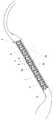
도 2는 본 발명의 실시예에 따른 심혈관용 스텐트의 사용 상태를 설명하기 위한 도면이다.2 is a view for explaining the state of use of the cardiovascular stent according to an embodiment of the present invention.
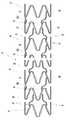
도 3은 본 발명의 실시예에 따른 심혈관용 스텐트의 스텐트 본체를 전개하여 나타낸 도면이다.Figure 3 is a view showing the development of the stent body of the cardiovascular stent in accordance with an embodiment of the present invention.
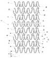
도 4 및 도 5는 본 발명의 실시예에 따른 심혈관용 스텐트의 수축 및 팽창 작용을 설명하기 위한 전개 도면이다.4 and 5 are exploded views for explaining the contraction and expansion of the cardiovascular stent according to an embodiment of the present invention.
도 6은 도 3의 링크들에 의해 스텐트 본체에 유연성이 부여된 상태를 설명하기 위한 도면이다.FIG. 6 is a view for explaining a state in which flexibility is provided to the stent body by the links of FIG. 3.
도 7은 본 발명의 실시예에 따른 심혈관용 스텐트의 작용을 설명하기 위한 도면이다.7 is a view for explaining the action of the cardiovascular stent according to an embodiment of the present invention.
본 발명은 심혈관용 스텐트에 관한 것으로, 더욱 상세하게는 인체의 관상동 맥과 같은 심혈관의 협착 부위를 원래 크기로 유지하는데 사용되며, 특히 심혈관의 협착 부위에 위치된 상태에서 분지(分枝) 혈관 통로를 용이하게 확보할 수 있는 심혈관용 스텐트에 관한 것이다.The present invention relates to a cardiovascular stent, and more particularly used to maintain the stenosis of the cardiovascular system, such as the coronary artery of the human body in its original size, especially branched vessels in the state located in the stenosis of the cardiovascular system It relates to a cardiovascular stent that can easily secure a passage.
일반적으로 인체의 관상동맥과 같은 심혈관은 심장벽으로 혈액을 보내고 심장 자체를 부양하는 역할을 하는 것으로서, 유전적 요인 또는 환경적 요인에 의해 혈관 내부에 협착 부위가 발생하면 이 협착 부위에 의해 혈액 공급이 원활하게 이루어지지 못하여 혈액 결핍 현상이 발생하거나 혈관 통로가 막히면서 협심증(狹心症)이나 심근경색(心筋梗塞)과 같은 각종 심장 질환을 유발한다.In general, cardiovascular vessels, such as the coronary arteries of the human body, send blood to the heart wall and support the heart itself. When stenosis occurs inside a blood vessel due to genetic or environmental factors, blood supply is provided by the stenosis. This is not done smoothly due to blood deficiency phenomenon or blockage of blood vessels causing various heart diseases such as angina (狹 心 症) and myocardial infarction (心 筋 梗塞).
이와 같이 심혈관 내부의 협착 부위를 원래의 상태로 유지하기 위한 확장 시술 작업에는 심혈관 통로에 대응하는 크기를 가지는 심혈관용 스텐트가 사용되며, 이 심혈관용 스텐트는 이미 잘 알려진 카테터 등과 같은 도구에 의해 통상의 방법으로 심혈관 내부에 삽입되어 협착 부위의 확장이 가능하게 위치된다.As described above, the cardiovascular stent having a size corresponding to the cardiovascular passage is used for the expansion procedure for maintaining the stenosis inside the cardiovascular vessel in its original state, and the cardiovascular stent is commonly used by a well-known catheter or the like. The method is inserted inside the cardiovascular vessel to allow for expansion of the stenosis site.
이러한 심혈관용 스텐트는 인체의 구강 내부에 시술되기 위하여 예를들면, 금속 와이어를 감는 방식으로 만드는 일반적인 스텐트와는 달리, 레이져 가공장치로 금속 재료를 가공하는 방식에 의해 지그재그 형태로 원주 방향을 따라 연결된 단위부재가 2개 이상 이격 형성되고, 이 각 단위부재들 사이사이에는 링크가 형성되어 이 링크들에 의해 서로 인접한 단위부재들이 적어도 2군데 이상의 지점이 연결되면서 가늘고 긴 원통형의 스텐트 본체가 만들어진다.The cardiovascular stent is connected to the circumferential direction in a zigzag form by processing a metal material with a laser processing device, unlike a common stent, for example, by winding a metal wire in order to be inserted into the oral cavity of a human body. Two or more unit members are formed, and a link is formed between each unit member so that at least two or more points of the unit members adjacent to each other are connected to each other by the links, thereby making a thin and long cylindrical stent body.
이와 같이 가공된 스텐트 본체는, 심혈관 내부에 삽입될 수 있는 크기를 가지며, 상기 단위부재와 링크들이 협착 부위에 위치된 상태에서 유연성은 물론이거 니와 팽창력이 부여되어 수축된 후 탄성력에 의해 원래의 상태로 팽창되면서 협착 부위가 복원될 수 있도록 되어 있다.The stent body processed in this way has a size that can be inserted into the cardiovascular system, and the elasticity after the contraction is given by the expansion force as well as the flexibility in the state in which the unit member and the link are located at the constriction site. As it expands, the constriction site can be restored.
그리고, 상기 각 링크들은 상기 단위부재와 단위부재 사이에 형성될 때 심혈관 내부의 협착 부위와 연통된 분지(分枝) 혈관이 막히지 않도록 상기 각 단위부재들 사이사이에서 충분한 개방공간이 확보될 수 있는 간격 및 배열을 가지는 상태로 이루어져야 한다. 이와 같이 인접한 단위부재와 단위부재 사이에서 상기 링크들에 의해 형성되는 개방공간은 상기 스텐트 본체가 협착 부위에 위치된 상태에서 분지 혈관 본연의 작용이 이루어지도록 함과 아울러 분지 혈관 내부에 각종 의료 시술이 가능하도록 하는 통로 역할을 한다.In addition, when each of the links is formed between the unit member and the unit member, sufficient open space may be secured between the unit members so that the branched blood vessel communicating with the constriction site inside the cardiovascular vessel is not blocked. It should be made with spaces and arrays. As such, the open space formed by the links between the adjacent unit member and the unit member allows the branched blood vessel to be intrinsically performed while the stent body is located at the constriction site, and various medical procedures are performed inside the branch blood vessel. It serves as a pathway to make it possible.
그러나, 상기한 종래의 심혈관용 스텐트들은, 상기 링크들이 단순하게 직선 또는 곡선의 연결 구간을 가지며 상기 단위부재와 단위부재 사이에서 원주 방향을 따라 동일한 배열을 가지며 이격 형성되므로 이와 같은 구조는 상기 링크들에 의해 인접한 단위부재들 사이의 공간이 과다하게 가려지면서 개방공간이 협소하게 형성되는 문제가 있다.However, the above-described conventional cardiovascular stents have a linking section of a straight line or a curved line and have the same arrangement along the circumferential direction between the unit member and the unit member, and thus the structure is spaced apart. There is a problem that the open space is narrowly formed while the space between the adjacent unit members is excessively covered by.
특히, 이러한 문제는 협착 부위와 연통된 분지 혈관을 가지는 심혈관 내부에 스텐트 본체가 삽입 된 후 이 스텐트 본체의 단위부재와 단위부재 사이에서 분지 혈관에 대응하는 통로를 확보하기 어렵고, 이로 인하여 분지 혈관 통로 일부 또는 전체가 가려지면서 의료적 부작용을 유발하는 한 요인이 될 수 있다.In particular, this problem is difficult to secure a passage corresponding to the branched blood vessel between the unit member and the unit member of the stent body after the stent body is inserted into the cardiovascular having a branched blood vessel in communication with the stricture site, thereby Some or all of these can be obstructed and cause a medical side effect.
또한, 상기와 같이 각 단위부재들 사이사이의 개방 공간이 협소해지면 예를들어, 카테터를 이용하여 협착 부위와 연통된 분지 혈관에 각종 의료 시술을 진행 할 때 만족할 만한 시술성을 얻기가 어렵다.In addition, when the open space between each unit member becomes narrow as described above, for example, it is difficult to obtain satisfactory operability when performing various medical procedures on branch vessels communicating with the stenosis using a catheter.
본 발명은 상기한 바와 같은 종래의 문제점을 해결하기 위하여 안출된 것으로서, 본 발명의 목적은 인체의 관상 동맥과 같은 심혈관의 협착 부위를 원래의 상태로 용이하게 유지할 수 있으며, 특히 스텐트가 협착 부위에 위치된 상태에서 이 스텐트에 의해 협착 부위와 연통된 분지 혈관 통로가 막히는 것을 개선한 심혈관용 스텐트를 제공하는데 있다.The present invention has been made to solve the conventional problems as described above, an object of the present invention can easily maintain the stenosis of the cardiovascular system, such as the coronary arteries of the human body in the original state, in particular the stent in the stenosis It is to provide a cardiovascular stent that improves the blockage of the branched vessel passages in communication with the stenosis site by the stent in the position.
상기한 바와 같은 본 발명의 목적을 실현하기 위하여,In order to realize the object of the present invention as described above,
원주 방향을 따라 지그재그 형태로 연결되는 복수개의 마디부를 가지며 탄성력에 의해 원주 방향 외측으로 팽창되면서 심혈관의 협착 부위가 원래의 크기로 유지되도록 적어도 2개 이상이 이격 형성되는 단위부재들과, 상기 각 단위부재들 사이사이에서 원주 방향을 따라 적어도 2군데 이상의 지점에 위치되어 심혈관 내부에서 분지 혈관 통로에 대응하는 개방 공간을 형성할 수 있는 연결 자세를 가지며 서로 인접한 단위부재들을 원통형상의 탄성체로 연결하기 위한 링크들을 포함하며,Unit members having a plurality of nodes connected in a zigzag form along the circumferential direction and at least two or more spaced apart from each other so as to expand the circumferential outward direction by elastic force so that the constriction portion of the cardiovascular vessel is maintained at its original size; A link for connecting unit members adjacent to each other with a cylindrical elastic body, having a connection posture which is located at least two points along the circumferential direction between the members to form an open space corresponding to the branched blood vessel passage within the cardiovascular system. Including the
상기 링크들은 상기 단위부재와 단위부재 사이의 2군데 이상의 연결 지점에서 2개가 1조로 각각 위치하고 이 2개의 링크 사이의 공간 확장을 위한 홈부를 형성하는 연결 구간을 가지며 2개의 홈부에 의해 링크 사이의 공간이 확장될 수 있는 대칭의 자세로 연결되는 것을 특징으로 하는 심혈관용 스텐트를 제공한다.The links have two connecting sections at two or more connection points between the unit member and the unit member, each having a connection section forming a groove for expanding the space between the two links, and the space between the links by the two grooves. It provides a cardiovascular stent, characterized in that connected in an expandable symmetrical posture.
이하, 첨부된 도면에 의거하여 본 발명의 바람직한 실시예를 설명한다. 본 발명의 실시예들은 당 업계에서 평균적인 지식을 가진 자들이 본 발명의 실시가 가능한 범위 내에서 설명된다.Hereinafter, preferred embodiments of the present invention will be described with reference to the accompanying drawings. Embodiments of the present invention are described to the extent that those of ordinary skill in the art can practice the present invention.
따라서, 본 발명의 실시예들은 여러가지 다른 형태로 변형될 수 있는 것이므로 본 발명의 특허청구범위는 아래에서 설명하는 실시예들로 인하여 한정되는 것은 아니다.Therefore, since the embodiments of the present invention may be modified in various other forms, the claims of the present invention are not limited to the embodiments described below.
도 1은 본 발명의 실시예에 따른 심혈관용 스텐트의 팽창 상태를 나타내는 도면으로서, 도면 부호 2는 스텐트 본체를 지칭한다.1 is a view showing an expanded state of the cardiovascular stent according to an embodiment of the present invention, 2 denotes the stent body.
이 스텐트 본체(2)는 도면에서와 같이 적어도 2개 이상의 단위부재(4)들이 수평하게 이격 배열되면서 가늘고 긴 원통의 형태로 이루어진다.The
상기 각 단위부재(4)들은 도 2에서와 같이 인체의 관상동맥과 같은 심혈관(V)의 관로(V1)에 대응하는 크기의 직경을 가지며 수축된 상태에서 탄성력에 의해 팽창하여 상기 관로(V1) 내부의 협착 부위(V2)가 원래의 상태로 유지될 수 있도록 하는 역할을 한다.Each of the unit members (4) has a diameter corresponding to the conduit (V1) of the cardiovascular (V), such as the coronary arteries of the human body as shown in Figure 2 and inflated by the elastic force in the contracted state (V1) It serves to maintain the internal constriction site (V2) in its original state.
도 3은 상기 스텐트 본체(2)를 형성하는 각 단위부재(6)들이 펼쳐진 상태를 나타내는 전개 도면으로서, 상기 각 단위부재(4)들은 반원 모양으로 절곡되면서 도면에서와 같이 통상의 밸리 지점과 피크 지점을 형성할 수 있도록 지그재그 형태로 연결되어 다수개의 마디부(B)를 가지는 구조로 전개된다.3 is an exploded view showing an unfolded state of each
그리고, 상기 각 단위부재(4)들은 도 3에서와 같이 복수개가 이격 배열될 때 상기 각 마디부(B)들이 동일한 지점에 각각 위치하는 배열을 가지도록 형성된다.Each of the
상기 각 단위부재(4)들은 통상의 의료용 스텐트 제작에 사용하는 금속 재질 중에서 코발트-크롬 합금이 사용될 수 있다. 이 코발트-크롬 합금은 의료 분야에서 예를들면, 고관절의 연결 등에 주로 사용하는 것으로서, 특히 니켈 성분의 함유량이 적어서 인체 내에서 알러지 반응(allergic reaction)을 최소화할 수 있고 내구성 및 내부식성, 내화학성 등이 우수하여 심혈관(V) 내부에서 각종 의료적 부작용을 방지할 수 있을 뿐만 아니라, 심혈관(V) 확장을 위한 본연의 기능을 용이하게 수행할 수 있는 재질 중에 하나이다.Each of the
상기 스텐트 본체(2)는 도면에는 나타내지 않았지만 이미 잘 알려진 레이져 가공장치를 이용한 통상의 레이져 가공 방식에 의해 코발트-크롬 합금의 금속 재료를 가공하여 상기 각 단위부재(4)들이 도 1에서와 같이 형성되면서 만들어진다.Although the
그리고, 상기 각 단위부재(4)들은 레이져 가공된 후 도면에는 나타내지 않았지만 예를들면, 폴리싱 장치를 이용하여 통상의 표면 연마 작업을 거치면서 상기 각 단위부재(4)들이 표면 엣지(edge)들이 라운드지게 표면 처리된다. 이러한 구조는 스텐트 본체(2)가 심혈관(V) 내부에 삽입된 후 관로(V1) 내벽면과 접촉하여 통증이나 상처 등이 발생하는 것을 억제하여 의료적 부작용을 줄일 수 있다.Although the
한편, 상기 각 단위부재(4)들 사이사이에는 도 1에서와 같이 적어도 2군데 이상의 지점에서 일정 간격을 두고 2개가 1조로 위치되는 링크(6)들이 형성되어 이 링크(6)에 의해 서로 인접한 단위부재(4)들이 유연성을 가지는 수평한 상태로 각각 연결된다.On the other hand, between each of the
상기 링크(6)는 상기 단위부재(4)와 단위부재(4) 사이에 형성될 때 심혈관(V)의 협착 부위(V2)와 연통된 분지 혈관(V3)에 대응하여 확장된 개방 면적을 제공할 수 있도록 이루어진다.When the
이를 위하여 본 실시예에서는 상기 각 링크(6)들이 도 3에서와 같이 어느 한 쪽으로 휘어져서 홈부(H)가 형성된 연결 구간을 가지며, 단위부재(4)와 단위부재(4) 사이의 둘레를 따라 2군데 이상의 지점에서 일정 간격을 두고 2개가 1조로 각각 위치될 때에 이들의 간격 틈새 공간이 상기 2개의 홈부(H)에 의해 도면에서와 같이 외측으로 확장될 수 있는 대칭 자세로 연결되어 마주하는 2개의 링크(6) 사이의 틈새 면적이 확장된 개방 공간(H1)이 제공되도록 하고 있다.To this end, in the present embodiment, each of the
상기 각 링크(6)들의 양측단은 상기 단위부재(4)들 사이사이에 연결될 때 도 3에서와 같이 서로 인접한 2개의 단위부재(4) 중에서 어느 하나의 단위부재(4)에는 1개의 마디부(B)를 사이에 두고 일측단이 연결된다. 그리고, 인접한 다른 하나의 단위부재(4)에는 2개의 마디부(B)를 사이에 두고 반대편 단부가 연결되면서 도면에서와 같은 배열로 상기 각 단위부재(4)들 사이사이에 형성된다.One end of each
이와 같이 상기 단위부재(4)들 사이에서 2개가 1조로 2군데 이상의 지점에 연결되는 링크(6)들은 상기 단위부재(4)들이 도 4에서와 같이 수축된 상태에서 팽창될 때 도 5에서와 같이 상기 마주하는 링크(6)들 사이로 더욱 확장된 개방 공간(H1)을 용이하게 확보할 수 있다. 즉, 상기 단위부재(4)들의 팽창시 상기 마주하는 링크(6)들의 연결 구간 간격이 벌어짐과 아울러, 상기 대칭 상태로 휘어진 홈부(H)들에 의해 상기 링크(6)들의 간격 틈새 공간보다 더욱 확장된 개방 공간(H1)이 제공된다.(도 5참조)As such, the
그리고, 상기 각 링크(6)들의 연결 구간 양끝단은 도 3에서와 같이 상기 단위부재(4)들의 마디부(B) 끝단에서 안쪽 지점까지 연장되어 도면에서와 같이 서로 인접한 단위부재(4)들의 간격(L1)보다 상기 링크(6)들의 길이(L2)가 긴 상태로 연결된다. 이와 같은 구조는 상기 단위부재(4)들 사이에서 더욱 확대된 개방 공간(H1)을 용이하게 확보할 수 있고, 상기 각 단위부재(4)들의 간격(L1)에 비하여 상 기 링크(6)들의 길이(L2)가 긴 상태로 연결되므로 상기 단위부재(4)들 사이에 한층 향상된 유연성이 부여된다.(도 6참조)In addition, both ends of the connection section of each of the
상기 각 링크(6)들은 레이져 가공장치로 상기 단위부재(4)들을 각각 가공하면서 스텐트 본체(2)를 만들 때 상기 각 단위부재(4)들 사이사이에서 상기와 같은 모양의 연결 구간을 가지도록 가공되면서 일체로 형성된다.Each of the
그리고, 상기 각 링크(6)들의 연결 구간은 상기 단위부재(4)들 사이사이에서 이 단위부재(4)를 형성하는 이음 구간의 굵기보다 가늘게 형성되어, 상기 각 단위부재(4)들 사이사이에서 유연성이 더욱 확보된 상태로 연결이 가능하도록 이루어진다.In addition, the connection section of each of the
상기한 구조로 이루어지는 본 발명의 실시예에 따른 심혈관용 스텐트는 도 7에서와 같이 인체의 관상 동맥과 같은 심혈관(V) 내부의 협착 부위(V2)를 원래의 상태로 유지하는 시술을 진행할 때, 상기 스텐트 본체(2)를 삽입하여 협착 부위(V2)를 원래의 상태로 유지할 수 있다.When the cardiovascular stent according to the embodiment of the present invention having the above-described structure maintains the constriction portion V2 inside the cardiovascular V such as the coronary artery of the human body as shown in FIG. 7, The
특히, 상기 스텐트 본체(2)가 삽입된 상태에서 협착 부위(V2)와 연통된 분지 혈관(V3)에 대응하여 확장된 개방 공간(H1)을 제공하여 상기 분지 혈관(V3) 본연의 기능을 저하시키지 않는 상태로 시술이 가능하다. 또한, 상기 확장된 개방 공간(H1)을 통하여 카테터 등으로 상기 분지 혈관(V3) 내부에 각종 의료 시술을 진행할 때 통로 공간의 확보가 용이하여 한층 향상된 시술성을 제공한다.In particular, in the state in which the stent
이상 설명한 바와 같이 본 발명은, 인체의 관상동맥과 같은 심혈관 내부의 협착 부위를 원래의 상태로 유지할 수 있으며, 특히 협착 부위와 연통된 분지(分枝) 혈관에 대응하는 개방 공간을 용이하게 확보할 수 있다.As described above, the present invention can maintain the stenosis inside the cardiovascular system such as the coronary artery of the human body in its original state, and in particular, can easily secure an open space corresponding to the branched blood vessel communicating with the stenosis site. Can be.
따라서, 인체의 관상동맥과 같은 심혈관의 협착 부위를 원래의 상태로 유지하기 위한 시술이 용이하고, 스텐트 삽입에 의해 각종 의료적 부작용이 발생하는 것을 최대한 방지할 수 있다.Therefore, the procedure for maintaining the stenosis of the cardiovascular system such as the coronary artery of the human body is easy, and it is possible to prevent various medical side effects from occurring due to the stent insertion.
Claims (4)
Translated fromKoreanPriority Applications (1)
| Application Number | Priority Date | Filing Date | Title |
|---|---|---|---|
| KR1020060024054AKR100758739B1 (en) | 2006-03-15 | 2006-03-15 | Cardiovascular Stents |
Applications Claiming Priority (1)
| Application Number | Priority Date | Filing Date | Title |
|---|---|---|---|
| KR1020060024054AKR100758739B1 (en) | 2006-03-15 | 2006-03-15 | Cardiovascular Stents |
Publications (1)
| Publication Number | Publication Date |
|---|---|
| KR100758739B1true KR100758739B1 (en) | 2007-09-14 |
Family
ID=38737815
Family Applications (1)
| Application Number | Title | Priority Date | Filing Date |
|---|---|---|---|
| KR1020060024054AActiveKR100758739B1 (en) | 2006-03-15 | 2006-03-15 | Cardiovascular Stents |
Country Status (1)
| Country | Link |
|---|---|
| KR (1) | KR100758739B1 (en) |
Citations (2)
| Publication number | Priority date | Publication date | Assignee | Title |
|---|---|---|---|---|
| KR0147482B1 (en)* | 1993-01-19 | 1998-08-01 | 알렌 제이. 스피겔 | Clad composite stent |
| KR20010106623A (en)* | 2000-05-22 | 2001-12-07 | 윤정한 | A metal stent for installation in the coronary artery |
- 2006
- 2006-03-15KRKR1020060024054Apatent/KR100758739B1/enactiveActive
Patent Citations (2)
| Publication number | Priority date | Publication date | Assignee | Title |
|---|---|---|---|---|
| KR0147482B1 (en)* | 1993-01-19 | 1998-08-01 | 알렌 제이. 스피겔 | Clad composite stent |
| KR20010106623A (en)* | 2000-05-22 | 2001-12-07 | 윤정한 | A metal stent for installation in the coronary artery |
Similar Documents
| Publication | Publication Date | Title |
|---|---|---|
| JP5259746B2 (en) | Lumen prosthesis | |
| US7611531B2 (en) | Stent | |
| EP1871292B1 (en) | Flexible stent | |
| CN104302250B (en) | uniformly expandable stent | |
| JP5095400B2 (en) | Flexible intravascular implant | |
| JP4097402B2 (en) | Expandable unit cell and intraluminal stent | |
| JP2005205238A (en) | Flexible expandable stent | |
| CA2439081A1 (en) | Longitudinally flexible stent | |
| AU2002304381A1 (en) | Longitudinally flexible stent | |
| EP1416882A2 (en) | Longitudinally flexible stent | |
| GB2514074A (en) | Stents with zero poisson's ratio cells | |
| CA2358453A1 (en) | Expandable endovascular medical tubular stent | |
| JP2011504407A (en) | Cylindrical stent | |
| JP5114353B2 (en) | Flexible expandable stent | |
| KR100267019B1 (en) | Stent for expanding body's lumen and method for manufacturing the same | |
| KR100758739B1 (en) | Cardiovascular Stents | |
| EP3895668A1 (en) | Stent and method for manufacturing same | |
| CN100591385C (en) | Extendable, flexible stent with excellent followability to vessels | |
| JP2003334255A (en) | Stents and stent grafts | |
| JP4835113B2 (en) | Stent | |
| JP2004313222A (en) | Flexible stent which is excellent in blood vessel followability and blood vessel diameter retainability, and evenly expands | |
| KR101127643B1 (en) | Cardiovascular stent | |
| JP4569262B2 (en) | Flexible stent with excellent blood vessel followability and expandability | |
| JP2001104488A (en) | Stent | |
| JP2004267492A (en) | Flexible stent with superior retention of blood vessel diameter |
Legal Events
| Date | Code | Title | Description |
|---|---|---|---|
| A201 | Request for examination | ||
| PA0109 | Patent application | St.27 status event code:A-0-1-A10-A12-nap-PA0109 | |
| PA0201 | Request for examination | St.27 status event code:A-1-2-D10-D11-exm-PA0201 | |
| P11-X000 | Amendment of application requested | St.27 status event code:A-2-2-P10-P11-nap-X000 | |
| P13-X000 | Application amended | St.27 status event code:A-2-2-P10-P13-nap-X000 | |
| D13-X000 | Search requested | St.27 status event code:A-1-2-D10-D13-srh-X000 | |
| D14-X000 | Search report completed | St.27 status event code:A-1-2-D10-D14-srh-X000 | |
| E902 | Notification of reason for refusal | ||
| PE0902 | Notice of grounds for rejection | St.27 status event code:A-1-2-D10-D21-exm-PE0902 | |
| E13-X000 | Pre-grant limitation requested | St.27 status event code:A-2-3-E10-E13-lim-X000 | |
| P11-X000 | Amendment of application requested | St.27 status event code:A-2-2-P10-P11-nap-X000 | |
| P13-X000 | Application amended | St.27 status event code:A-2-2-P10-P13-nap-X000 | |
| R18-X000 | Changes to party contact information recorded | St.27 status event code:A-3-3-R10-R18-oth-X000 | |
| E701 | Decision to grant or registration of patent right | ||
| PE0701 | Decision of registration | St.27 status event code:A-1-2-D10-D22-exm-PE0701 | |
| GRNT | Written decision to grant | ||
| PR0701 | Registration of establishment | St.27 status event code:A-2-4-F10-F11-exm-PR0701 | |
| PR1002 | Payment of registration fee | St.27 status event code:A-2-2-U10-U11-oth-PR1002 Fee payment year number:1 | |
| PG1601 | Publication of registration | St.27 status event code:A-4-4-Q10-Q13-nap-PG1601 | |
| G170 | Re-publication after modification of scope of protection [patent] | ||
| PG1701 | Publication of correction | St.27 status event code:A-5-5-P10-P19-oth-PG1701 Patent document republication publication date:20080421 Republication note text:Request for Correction Notice (Document Request) Gazette number:1007587390000 Gazette reference publication date:20070914 | |
| R18-X000 | Changes to party contact information recorded | St.27 status event code:A-5-5-R10-R18-oth-X000 | |
| PR1001 | Payment of annual fee | St.27 status event code:A-4-4-U10-U11-oth-PR1001 Fee payment year number:4 | |
| PR1001 | Payment of annual fee | St.27 status event code:A-4-4-U10-U11-oth-PR1001 Fee payment year number:5 | |
| FPAY | Annual fee payment | Payment date:20120907 Year of fee payment:6 | |
| PR1001 | Payment of annual fee | St.27 status event code:A-4-4-U10-U11-oth-PR1001 Fee payment year number:6 | |
| P22-X000 | Classification modified | St.27 status event code:A-4-4-P10-P22-nap-X000 | |
| FPAY | Annual fee payment | Payment date:20130628 Year of fee payment:7 | |
| PR1001 | Payment of annual fee | St.27 status event code:A-4-4-U10-U11-oth-PR1001 Fee payment year number:7 | |
| R18-X000 | Changes to party contact information recorded | St.27 status event code:A-5-5-R10-R18-oth-X000 | |
| FPAY | Annual fee payment | Payment date:20140905 Year of fee payment:8 | |
| PR1001 | Payment of annual fee | St.27 status event code:A-4-4-U10-U11-oth-PR1001 Fee payment year number:8 | |
| FPAY | Annual fee payment | Payment date:20150818 Year of fee payment:9 | |
| PR1001 | Payment of annual fee | St.27 status event code:A-4-4-U10-U11-oth-PR1001 Fee payment year number:9 | |
| P14-X000 | Amendment of ip right document requested | St.27 status event code:A-5-5-P10-P14-nap-X000 | |
| P22-X000 | Classification modified | St.27 status event code:A-4-4-P10-P22-nap-X000 | |
| FPAY | Annual fee payment | Payment date:20160906 Year of fee payment:10 | |
| PR1001 | Payment of annual fee | St.27 status event code:A-4-4-U10-U11-oth-PR1001 Fee payment year number:10 | |
| P14-X000 | Amendment of ip right document requested | St.27 status event code:A-5-5-P10-P14-nap-X000 | |
| FPAY | Annual fee payment | Payment date:20170905 Year of fee payment:11 | |
| PR1001 | Payment of annual fee | St.27 status event code:A-4-4-U10-U11-oth-PR1001 Fee payment year number:11 | |
| P22-X000 | Classification modified | St.27 status event code:A-4-4-P10-P22-nap-X000 | |
| FPAY | Annual fee payment | Payment date:20180828 Year of fee payment:12 | |
| PR1001 | Payment of annual fee | St.27 status event code:A-4-4-U10-U11-oth-PR1001 Fee payment year number:12 | |
| FPAY | Annual fee payment | Payment date:20190906 Year of fee payment:13 | |
| PR1001 | Payment of annual fee | St.27 status event code:A-4-4-U10-U11-oth-PR1001 Fee payment year number:13 | |
| PR1001 | Payment of annual fee | St.27 status event code:A-4-4-U10-U11-oth-PR1001 Fee payment year number:14 | |
| PR1001 | Payment of annual fee | St.27 status event code:A-4-4-U10-U11-oth-PR1001 Fee payment year number:15 | |
| R18-X000 | Changes to party contact information recorded | St.27 status event code:A-5-5-R10-R18-oth-X000 | |
| PR1001 | Payment of annual fee | St.27 status event code:A-4-4-U10-U11-oth-PR1001 Fee payment year number:16 | |
| R18-X000 | Changes to party contact information recorded | St.27 status event code:A-5-5-R10-R18-oth-X000 | |
| PR1001 | Payment of annual fee | St.27 status event code:A-4-4-U10-U11-oth-PR1001 Fee payment year number:17 | |
| R18-X000 | Changes to party contact information recorded | St.27 status event code:A-5-5-R10-R18-oth-X000 | |
| PR1001 | Payment of annual fee | St.27 status event code:A-4-4-U10-U11-oth-PR1001 Fee payment year number:18 | |
| PR1001 | Payment of annual fee | St.27 status event code:A-4-4-U10-U11-oth-PR1001 Fee payment year number:19 |