KR100755570B1 - Infrared heat shrink tube heater - Google Patents
Infrared heat shrink tube heaterDownload PDFInfo
- Publication number
- KR100755570B1 KR100755570B1KR1020060022196AKR20060022196AKR100755570B1KR 100755570 B1KR100755570 B1KR 100755570B1KR 1020060022196 AKR1020060022196 AKR 1020060022196AKR 20060022196 AKR20060022196 AKR 20060022196AKR 100755570 B1KR100755570 B1KR 100755570B1
- Authority
- KR
- South Korea
- Prior art keywords
- tube
- tube wire
- heat shrink
- heating
- shrink tube
- Prior art date
- Legal status (The legal status is an assumption and is not a legal conclusion. Google has not performed a legal analysis and makes no representation as to the accuracy of the status listed.)
- Expired - Fee Related
Links
Images

Classifications
- B—PERFORMING OPERATIONS; TRANSPORTING
- B29—WORKING OF PLASTICS; WORKING OF SUBSTANCES IN A PLASTIC STATE IN GENERAL
- B29C—SHAPING OR JOINING OF PLASTICS; SHAPING OF MATERIAL IN A PLASTIC STATE, NOT OTHERWISE PROVIDED FOR; AFTER-TREATMENT OF THE SHAPED PRODUCTS, e.g. REPAIRING
- B29C61/00—Shaping by liberation of internal stresses; Making preforms having internal stresses; Apparatus therefor
- B29C61/02—Thermal shrinking
- B29C61/025—Thermal shrinking for the production of hollow or tubular articles
- B—PERFORMING OPERATIONS; TRANSPORTING
- B29—WORKING OF PLASTICS; WORKING OF SUBSTANCES IN A PLASTIC STATE IN GENERAL
- B29D—PRODUCING PARTICULAR ARTICLES FROM PLASTICS OR FROM SUBSTANCES IN A PLASTIC STATE
- B29D23/00—Producing tubular articles
- B29D23/001—Pipes; Pipe joints
- B—PERFORMING OPERATIONS; TRANSPORTING
- B29—WORKING OF PLASTICS; WORKING OF SUBSTANCES IN A PLASTIC STATE IN GENERAL
- B29L—INDEXING SCHEME ASSOCIATED WITH SUBCLASS B29C, RELATING TO PARTICULAR ARTICLES
- B29L2031/00—Other particular articles
- B29L2031/707—Cables, i.e. two or more filaments combined together, e.g. ropes, cords, strings, yarns
Landscapes
- Engineering & Computer Science (AREA)
- Mechanical Engineering (AREA)
- Manufacturing & Machinery (AREA)
- Physics & Mathematics (AREA)
- Thermal Sciences (AREA)
- Resistance Heating (AREA)
- Lining Or Joining Of Plastics Or The Like (AREA)
Abstract
Translated fromKoreanDescription
Translated fromKorean본 명세서에 첨부되는 다음의 도면들은 본 발명의 바람직한 실시예를 예시하는 것이며, 후술하는 발명의 상세한 설명과 함께 본 발명의 기술사상을 더욱 이해시키는 역할을 하는 것이므로, 본 발명은 그러한 도면에 기재된 사항에만 한정되어 해석되어서는 아니된다.The following drawings attached to this specification are illustrative of preferred embodiments of the present invention, and together with the detailed description of the invention to serve to further understand the technical spirit of the present invention, the present invention is a matter described in such drawings It should not be construed as limited to
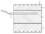
도 1은 종래기술에 따른 히팅 드럼을 이용한 가열장치를 나타내는 개략도이다.1 is a schematic view showing a heating apparatus using a heating drum according to the prior art.
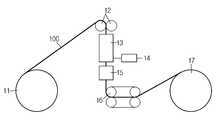
도 2는 본 발명의 바람직한 실시예에 따른 열 수축 튜브의 팽창 장치를 나타내는 개념도이다.2 is a conceptual diagram showing a device for expanding a heat shrinkable tube according to a preferred embodiment of the present invention.
도 3은 본 발명의 바람직한 실시예에 따른 열 수축 튜브의 팽창 장치에 구비되는 적외선 가열장치를 나타내는 개략도이다.Figure 3 is a schematic diagram showing an infrared heating device provided in the expansion device of the heat shrinkable tube according to a preferred embodiment of the present invention.
<도면의 주요 참조부호에 대한 설명><Description of main reference numerals in the drawings>
11...인출기12...핀치롤11
13...적외선 가열장치14...가열장치 제어기13
15...팽창장치16...인취기15 ...
17...권취보빈100...튜브 선재17.Rolling
131...적외선 램프132...보호막131
133...반사판133 ... Reflection
본 발명은 열 수축 튜브 가열 장치에 관한 것으로서, 더욱 상세하게는 열 수축 튜브를 팽창시키는 공정에서 열 수축 튜브를 가열하는 수단을 개선한 장치에 관한 것이다.The present invention relates to a heat shrink tube heating apparatus, and more particularly, to an apparatus that improves a means for heating a heat shrink tube in a process of expanding the heat shrink tube.
열수축 튜브는 가열 후에 경화시키면, 직경 또는 길이가 수축되는 특성을 가지는 것으로 피복전선이나 관로 등의 연결부위를 기밀하게 커버하거나 또는 병이나 건전지의 외주면에 끼워져서 포장용으로도 사용된다.When heat-shrinkable tubes are cured after heating, they have a property of shrinking in diameter or length. The heat-shrink tubes are also used for packaging by tightly covering the connecting portions such as coated wires or pipes or by fitting them to the outer circumferential surface of a bottle or a battery.
열수축 튜브는 열가소성 수지를 이용하여 튜브 선재를 압출 성형하는 공정과, 압출 성형된 선재를 가교하는 공정과, 튜브의 직경을 팽창시키는 공정으로 이루어진다.The heat shrink tube comprises a process of extruding a tube wire rod using a thermoplastic resin, a process of crosslinking the extruded wire rod, and a process of expanding the diameter of the tube.
특히, 튜브의 직경을 팽창시키는 공정은 크게, 히팅 드럼을 사용하여 가교된 선재를 팽창하기에 충분한 온도로 가열하는 공정과, 내부의 압력 공기를 인가하여 소망하는 직경의 튜브 선재로 팽창시키는 공정과, 팽창된 튜브 선재를 인취기를 통해 보빈에 최종적으로 권취하는 공정으로 이루어진다.In particular, the process of expanding the diameter of the tube is largely performed by heating to a temperature sufficient to expand the crosslinked wire rod using a heating drum, and expanding the tube wire of a desired diameter by applying internal pressure air; In this case, the expanded tube wire is finally wound onto the bobbin through a take-up machine.
도 1은 종래기술에 따른 히팅 드럼을 이용한 가열장치를 나타내는 개략도이 다. 도 1을 참조하면, 가열장치는 히터(2)가 내장되는 내부 롤(1)과, 상기 내부 롤(1)을 감싸는 외부 실린더(5)를 구비한다. 이때, 외부 실린더(5)의 외주면에는 그루브(6)가 형성되는데, 열 수축 튜브가 그루브(6)를 통과하면서 히터(2)에 의해 전해진 열에 의해 가열된다.1 is a schematic diagram showing a heating apparatus using a heating drum according to the prior art. Referring to FIG. 1, the heating apparatus includes an
히팅 드럼을 이용하여 튜브를 가열할 경우 외부 실린더(5)와 접촉하는 부분만 국부적으로 가열되어 튜브가 고르게 가열되지 않는다. 또한, 튜브가 그루브(6)내에서 연속적으로 가열되므로, 외부 실린더(5)로부터 인출되는 부분에서, 튜브가 외부 실린더(5)와 접촉하는 부분과 비 접촉부분의 온도 차이는 더욱 심하게 발생한다. 따라서, 튜브 팽창시에 가열된 특정 부위만 팽창하는 편심불량이 발생한다.When the tube is heated using a heating drum, only the portion in contact with the
또한, 히팅 드럼을 예열하기 위해서는 많은 시간이 소요되므로, 작업이 끝났을 경우에도 다음 작업을 위하여 히터(2)를 계속 가동해야 하는 경우가 있다. 이러한 경우, 히터(2) 가열을 위해 많은 전력을 소모하게 되어 제조비용이 상승하는 문제가 발생한다.In addition, since it takes a long time to preheat the heating drum, there is a case where the
또한, 튜브가 그루브(6)를 따라 진행 방향으로 이동하게 되는데, 이때, 접촉면의 고열로 인하여 튜브 내부에 있는 첨가제가 미세하게 누출되어 드럼의 그루브(6)에 부착된다. 따라서, 시간이 지남에 따라 그루브(6)에 이물질이 축적되어 열전달 효율이 감소하는 문제가 발생한다. 또한, 이물질이 튜브의 슬립을 방해하여 튜브가 길이 방향으로 늘어나는 불량을 일으킨다.In addition, the tube is moved along the groove 6 in the direction of travel, whereby the additives inside the tube are finely leaked due to the high heat of the contact surface and attached to the groove 6 of the drum. Therefore, as time passes, foreign matter accumulates in the grooves 6, which causes a problem of decreasing heat transfer efficiency. In addition, foreign matters interfere with the slip of the tube, causing the tube to stretch in the longitudinal direction.
본 발명은 상기와 같은 문제점을 해결하기 위해 창안된 것으로서, 열 수축 튜브 가열장치가 열 수축 튜브와 직접적으로 접촉하지 않고 열 수축 튜브를 가열할 수 있도록 하는 것을 목적으로 한다.The present invention has been made to solve the above problems, and an object thereof is to enable a heat shrink tube heating apparatus to heat a heat shrink tube without directly contacting the heat shrink tube.
상기와 같은 목적을 달성하기 위하여 본 발명의 일 측면에 따른 열 수축 튜브 팽창장치에서 열 수축 튜브를 가열하기 위하여 구비되는 장치에 있어서, 열 수축 튜브가 지나가는 경로 상에 적외선을 주사하여 상기 열 수축 튜브를 가열시킬 수 있는 적외선 가열장치를 구비한다.In the apparatus provided for heating the heat shrink tube in the heat shrink tube expansion device according to an aspect of the present invention to achieve the above object, the heat shrink tube by scanning infrared radiation on the path passing through the heat shrink tube It is provided with an infrared heating device capable of heating.
상기 적외선 가열장치는 적외선을 발생시켜 외부로 빛과 열에너지를 방출하는 적어도 하나 이상의 적외선 램프; 및 상기 적외선 램프와 튜브의 이동 경로 사이에 마련되는 보호막;을 구비하며, 상기 보호막은 석영으로 구성되는 것이 바람직하다.The infrared heater includes at least one infrared lamp for generating infrared light to emit light and heat energy to the outside; And a protective film provided between the infrared lamp and the moving path of the tube, wherein the protective film is made of quartz.
바람직하게, 상기 적외선 가열장치는 상기 적외선 램프를 중심으로 상기 보호막과 대향되는 부분에 반사판을 더 구비한다.Preferably, the infrared heater further includes a reflecting plate at a portion of the infrared lamp facing the protective film.
바람직하게, 상기 반사판은 금으로 도금 처리된 금속판, 알루미늄판을 연마한 판, 또는 구리판을 연마한 판일 수 있다.Preferably, the reflecting plate may be a metal plate coated with gold, a plate polished with an aluminum plate, or a plate polished with a copper plate.
또한, 상기 적외선 램프는 필라멘트와 상기 필라멘트를 고정할 수 있는 고정 지지대를 구비하는 것이 바람직하다.In addition, the infrared lamp is preferably provided with a fixing support for fixing the filament and the filament.
본 발명의 다른 측면에 따른 열 수축 튜브 가열방법은 열 수축 튜브 팽창방법에서 열 수축 튜브를 가열하는 방법에 있어서, 열 수축 튜브가 지나가는 경로 상에 적외선을 주사하여 상기 열 수축 튜브를 가열한다.The heat shrink tube heating method according to another aspect of the present invention is a method of heating a heat shrink tube in a heat shrink tube expansion method, wherein the heat shrink tube is heated by scanning infrared rays through a path through which the heat shrink tube passes.
이하, 첨부된 도면을 참조하여 본 발명의 바람직한 실시예를 상세히 설명하기로 한다. 이에 앞서, 본 명세서 및 청구범위에 사용된 용어나 단어는 통상적이거나 사전적인 의미로 한정해서 해석되어서는 아니되며, 발명자는 그 자신의 발명을 가장 최선의 방법으로 설명하기 위해 용어의 개념을 적절하게 정의할 수 있다는 원칙에 입각하여 본 발명의 기술적 사상에 부합하는 의미와 개념으로 해석되어야만 한다. 따라서, 본 명세서에 기재된 실시예와 도면에 도시된 구성은 본 발명의 가장 바람직한 일 실시예에 불과할 뿐이고 본 발명의 기술적 사상을 모두 대변하는 것은 아니므로, 본 출원시점에 있어서 이들을 대체할 수 있는 다양한 균등물과 변형예들이 있을 수 있음을 이해하여야 한다.Hereinafter, exemplary embodiments of the present invention will be described in detail with reference to the accompanying drawings. Prior to this, terms or words used in the specification and claims should not be construed as having a conventional or dictionary meaning, and the inventors should properly explain the concept of terms in order to best explain their own invention. Based on the principle that can be defined, it should be interpreted as meaning and concept corresponding to the technical idea of the present invention. Therefore, the embodiments described in the specification and the drawings shown in the drawings are only the most preferred embodiment of the present invention and do not represent all of the technical idea of the present invention, various modifications that can be replaced at the time of the present application It should be understood that there may be equivalents and variations.
도 2는 본 발명의 바람직한 실시예에 따른 열 수축 튜브의 팽창 장치를 나타내는 개념도이다.2 is a conceptual diagram showing a device for expanding a heat shrinkable tube according to a preferred embodiment of the present invention.
도 2를 참조하면, 본 발명의 실시예에 따른 열 수축 튜브의 팽창 장치는 가교된 튜브 선재(100)를 공급하는 인출기(11), 튜브 선재(100)를 다음 공정을 진행하기 위한 장치로 유도하는 핀치롤(12), 튜브 선재(100)를 가열하는 가열장치(13), 가열장치(13)의 환경에 따라 작동을 제어하는 가열장치 제어기(14), 가열된 튜브 선재(100)에 음압을 인가하여 팽창 가공하는 팽창장치(15), 가공이 완료된 튜브 선재(100)를 일정 속도로 인발하는 인취기(16), 및 완성된 튜브 선재(100)를 보빈에 감는 권취기(17)를 구비한다.Referring to Figure 2, the expansion device of the heat shrinkable tube according to an embodiment of the present invention guides the
인출기(11)는 가교된 튜브 선재가 감겨져 있는 보빈을 회전시킴으로써, 상기 보빈에 감겨있는 튜브 선재(100)를 핀치롤(12)로 공급한다.The
핀치롤(12)은 인출기(11)에서 공급되는 튜브 선재(100)를 가열장치(13)로 가이드 한다.The
가열장치(13)는 녹는점 이상의 온도를 유지하는 압출, 성형된 튜브 선재(100)에 적외선을 이용하여 가열함으로써 가교된 튜브 선재(100)를 팽창하기에 충분한 온도로 가열시킨다. 이 가열장치(13)는 튜브 선재(100)의 외주면을 둘러싸는 4개의 4kW 적외선 램프(131)와, 이 적외선 램프(131)로부터 발산되는 빛 중에서 튜브가 위치하는 방향의 반대방향으로 발산되는 빛을 튜브가 위치하는 방향으로 반사시키기 위한 반사판(133)으로 이루어진다(도 3참조).The
적외선 램프(131)는 필라멘트(미 도시)를 구비하며, 상기 필라멘트에 전원으로부터 인가되는 전류를 흐르게 하여 적외선 파장영역에 해당하는 빛과 열을 발생시킨다.The
적외선 램프(131)로는 예컨대, 온도조절이 가능한 텅스텐 필라멘트 벌브가 사용될 수 있다. 비록 본 발명의 실시예에서, 적외선 램프(131)를 텅스텐 필라멘트 벌브로 예시하였으나, 본 발명이 이를 한정하는 것은 아니다.As the
바람직하게, 적외선 램프(131)는 고온에서 필라멘트가 중력방향으로 쳐지는 것을 방지하기 위한 지지대(미도시)를 더 구비할 수 있다.Preferably, the
또한, 가열장치(13)는 튜브 선재(100)의 단선으로 인한 적외선 램프(131)의 파손 또는 열 수축 튜브의 가열로 인하여 발생하는 흄(fume)이 적외선 램프(131)의 표면에 부착되는 것을 방지하기 위하여 보호막(132)을 더 구비한다.In addition, the
보호막(132)은 튜브 선재(100)와 적외선 램프(131)사이에 구비된다.The
또한, 보호막(132)은 적외선 램프(131)에서 발산하는 열과 빛을 튜브(100)에 충분히 전달하기 위해서 양호한 열 전도성, 높은 방사율 및 전기 절연성이 좋은 석영물질로 이루어진다.In addition, the
반사판(133)은 적외선 램프(131)를 중심으로 보호막(132)이 위치하는 방향 (또는 튜브(100)가 위치하는 방향)과 대향되는 방향에 구비된다.The reflecting
반사판(133)은 적외선 램프(131)가 위치하는 방향으로 오목한 반원이나 포물선 형태를 지닌다. 이에 따라, 반사판(133)을 통해 적외선 램프(131)로부터 발산되는 빛 중에서, 튜브가 위치하는 방향의 반대방향(즉, 반사판(133)이 위치하는 방향)으로 발산되는 빛을 튜브가 위치하는 방향으로 집중시키거나, 평행광으로 조사할 수 있다.The reflecting
반사판(133)은 금속판에 반사효율이 좋은 금을 도금한 금 도금판, 또는 알루미늄이나 구리판을 연마한 금속판을 사용하는 것이 바람직하다.As the reflecting
적외선은 단위면적당 에너지가 높으며, 에너지를 반사,투과,흡수되는 물질과 충돌하기 전까지 전자기파의 형태로 빛의 속도로 전달하므로, 튜브(100)를 단시간에 가열할 수 있다. 또한, 비접촉방식으로 열을 전달하므로 튜브를 훼손시키지 않고 고르게 가열할 수 있다.Infrared light has a high energy per unit area, and transmits energy at the speed of light in the form of electromagnetic waves until it collides with a material that is reflected, transmitted, and absorbed, and thus, the
가열장치 제어기(14)는 가열장치(13) 내부의 온도를 모니터링하여 가열장치(13) 내부의 온도 환경이 튜브 선재(100)의 연화점 이상의 온도로 유지되도록 적외선 램프(131)의 구동을 제어한다.The
팽창장치(15)는 가열된 튜브 선재(100)에 음압을 인가하여 팽창시키고, 튜브 선재(100)를 냉각수를 이용하여 냉각시킨다.The
인취기(16)는 팽창된 튜브 선재(100)를 일정한 속도로 인발하여 권취보빈(17)에 권취시킨다.The take-up
이하, 전술한 구성요소를 참조하여 본 발명의 실시예에 따른 열 수축 튜브의 팽창 장치의 동작을 설명한다.Hereinafter, the operation of the expansion device of the heat shrinkable tube according to the embodiment of the present invention with reference to the above-described components.
우선, 인출기(11)의 가동으로, 가교된 튜브 선재(100)가 감긴 보빈이 회전하고, 가교된 튜브 선재(100)가 핀치롤(12)을 통해 가열장치(13)로 공급된다.First, with the operation of the
가열장치(13)의 내부에 구비되는 4개의 4kW 적외선 램프(131)는 적외선 역역의 파장을 지니는 빛과 열을 발생시킨다. 적외선 램프(131)로부터 발생되는 빛은 튜브 선재(100)에 직접 조사되거나, 반사판(133)을 통해 굴절되어 튜브 선재(100)에 조사된다. 이때, 가열장치(13)의 내부의 온도는 가열장치 제어기(14)에 의해 튜브 선재(100) 연화점 이상의 온도로 유지된다.Four 4kW
가열장치(13)를 통해 연화점 이상으로 가열된 튜브 선재(100)는 팽창장치(15)를 통과한다. 팽창장치(15)에서는 연화점 이상으로 가열된 상기 튜브 선재(100)에 음압을 인가하여 내부에 공간이 형성되도록 팽창시키고, 냉각시킨다.The
마지막으로, 내부에 소정의 공간이 형성된 상태로 냉각된 튜브 선재(100)를 인취기(16)를 통해 일정한 속도로 인발하여 권취보빈(17)에 권취시킨다.Finally, the
이상에서 본 발명은 비록 한정된 실시예와 도면에 의해 설명되었으나, 본 발명은 이것에 의해 한정되지 않으며 본 발명이 속하는 기술분야에서 통상의 지식을 가진 자에 의해 본 발명의 기술사상과 아래에 기재될 특허청구범위의 균등범위 내 에서 다양한 수정 및 변형이 가능함은 물론이다.Although the present invention has been described above by means of limited embodiments and drawings, the present invention is not limited thereto and will be described below by the person skilled in the art to which the present invention pertains. Of course, various modifications and variations are possible within the scope of the claims.
본 발명에 따르면, 열 수축 튜브를 팽창시키는 공정에서 열 수축 튜브를 비 접촉식으로 가열함으로써, 국부 가열로 인하여 발생하는 편심불량을 방지할 수 있다.According to the present invention, by heating the heat shrink tube non-contacted in the process of expanding the heat shrink tube, it is possible to prevent the eccentricity caused by the local heating.
또한, 열 수축 튜브를 비 접촉식으로 가열함으로써, 튜브 내부의 첨가제의 의하여 발생하는 이물질 생성을 원천적으로 방지할 수 있다.In addition, by heating the heat shrink tube non-contact, it is possible to prevent the generation of foreign matters generated by the additives inside the tube.
또한, 적외선 램프를 이용한 복사 에너지를 이용함으로써, 가열장치의 에너지 효율을 높일 수 있다.Moreover, the energy efficiency of a heating apparatus can be improved by using the radiant energy which used an infrared lamp.
Claims (9)
Translated fromKoreanPriority Applications (1)
| Application Number | Priority Date | Filing Date | Title |
|---|---|---|---|
| KR1020060022196AKR100755570B1 (en) | 2006-03-09 | 2006-03-09 | Infrared heat shrink tube heater |
Applications Claiming Priority (1)
| Application Number | Priority Date | Filing Date | Title |
|---|---|---|---|
| KR1020060022196AKR100755570B1 (en) | 2006-03-09 | 2006-03-09 | Infrared heat shrink tube heater |
Publications (1)
| Publication Number | Publication Date |
|---|---|
| KR100755570B1true KR100755570B1 (en) | 2007-09-06 |
Family
ID=38736531
Family Applications (1)
| Application Number | Title | Priority Date | Filing Date |
|---|---|---|---|
| KR1020060022196AExpired - Fee RelatedKR100755570B1 (en) | 2006-03-09 | 2006-03-09 | Infrared heat shrink tube heater |
Country Status (1)
| Country | Link |
|---|---|
| KR (1) | KR100755570B1 (en) |
Cited By (2)
| Publication number | Priority date | Publication date | Assignee | Title |
|---|---|---|---|---|
| CN106182731A (en)* | 2016-08-29 | 2016-12-07 | 科睿驰(北京)医疗科技发展有限公司 | Conduit bar footpath contracting equipment |
| CN109747145A (en)* | 2019-01-23 | 2019-05-14 | 滨州中润三元管道科技有限公司 | Crosslinking with radiation thermal shrinkable sleeve extension fixture |
Citations (3)
| Publication number | Priority date | Publication date | Assignee | Title |
|---|---|---|---|---|
| JPS5653042A (en) | 1979-10-09 | 1981-05-12 | Mitsubishi Plastics Ind Ltd | Production of heat-shrinkable tube |
| KR19990063608A (en)* | 1995-09-20 | 1999-07-26 | 아케 브롬, 라르스 호빙 | Polymer heating and / or crosslinking method and apparatus |
| KR20050062520A (en)* | 2002-08-02 | 2005-06-23 | 웨이퍼마스터스, 인코퍼레이티드 | Hot plate annealing |
- 2006
- 2006-03-09KRKR1020060022196Apatent/KR100755570B1/ennot_activeExpired - Fee Related
Patent Citations (3)
| Publication number | Priority date | Publication date | Assignee | Title |
|---|---|---|---|---|
| JPS5653042A (en) | 1979-10-09 | 1981-05-12 | Mitsubishi Plastics Ind Ltd | Production of heat-shrinkable tube |
| KR19990063608A (en)* | 1995-09-20 | 1999-07-26 | 아케 브롬, 라르스 호빙 | Polymer heating and / or crosslinking method and apparatus |
| KR20050062520A (en)* | 2002-08-02 | 2005-06-23 | 웨이퍼마스터스, 인코퍼레이티드 | Hot plate annealing |
Cited By (2)
| Publication number | Priority date | Publication date | Assignee | Title |
|---|---|---|---|---|
| CN106182731A (en)* | 2016-08-29 | 2016-12-07 | 科睿驰(北京)医疗科技发展有限公司 | Conduit bar footpath contracting equipment |
| CN109747145A (en)* | 2019-01-23 | 2019-05-14 | 滨州中润三元管道科技有限公司 | Crosslinking with radiation thermal shrinkable sleeve extension fixture |
Similar Documents
| Publication | Publication Date | Title |
|---|---|---|
| US6643476B1 (en) | Image forming apparatus with accurate temperature control for various media having different thickness | |
| US20020051663A1 (en) | Heating mechanism for use in image forming apparatus | |
| US9743478B2 (en) | Light intensity adjustable ultraviolet device for curing optical fiber coating | |
| US5790752A (en) | Efficient in-line fluid heater | |
| CN101890806B (en) | For heated method and the preheating device of precast body before moulding prefabricated body is with formation container | |
| CN103319100A (en) | Ultraviolet curing equipment and method for optical fiber coating | |
| WO2003002329A1 (en) | Method and device for heating preform | |
| KR100755570B1 (en) | Infrared heat shrink tube heater | |
| US5887238A (en) | Toner printing machine and method for fixing toner image | |
| KR102706653B1 (en) | Heating lamp | |
| JP2022137221A (en) | Workpiece dividing device and workpiece dividing method | |
| US4543472A (en) | Plane light source unit and radiant heating furnace including same | |
| US8866051B2 (en) | Apparatus and method for applying a protective element on an optical waveguide | |
| KR100755571B1 (en) | Method of manufacturing heat shrink tube using infrared crosslinking | |
| JP5608177B2 (en) | Method and apparatus for fusing recording materials into media | |
| KR100628602B1 (en) | Infrared wire crosslinking device | |
| KR100737612B1 (en) | Crosslinking device and method using infrared heater | |
| US4540911A (en) | Halogen lamp unit | |
| JP2011177926A (en) | Near infrared ray heater and method of heating preform | |
| CN113015708A (en) | Emitter system for illuminating laminated glass panels of different widths | |
| KR100860181B1 (en) | Multi-irradiation crosslinking apparatus and method using infrared rays | |
| RU2776495C1 (en) | Emitting system for irradiating multilayer glass panes of different widths, apparatus for cutting glass using the emitting system, method for producing the emitting system, and application thereof | |
| KR20070024348A (en) | Fusing Heater | |
| KR101214157B1 (en) | Lamp for fixing | |
| JP3558161B2 (en) | Heating roller |
Legal Events
| Date | Code | Title | Description |
|---|---|---|---|
| A201 | Request for examination | ||
| PA0109 | Patent application | St.27 status event code:A-0-1-A10-A12-nap-PA0109 | |
| PA0201 | Request for examination | St.27 status event code:A-1-2-D10-D11-exm-PA0201 | |
| D13-X000 | Search requested | St.27 status event code:A-1-2-D10-D13-srh-X000 | |
| D14-X000 | Search report completed | St.27 status event code:A-1-2-D10-D14-srh-X000 | |
| E902 | Notification of reason for refusal | ||
| PE0902 | Notice of grounds for rejection | St.27 status event code:A-1-2-D10-D21-exm-PE0902 | |
| E13-X000 | Pre-grant limitation requested | St.27 status event code:A-2-3-E10-E13-lim-X000 | |
| P11-X000 | Amendment of application requested | St.27 status event code:A-2-2-P10-P11-nap-X000 | |
| P13-X000 | Application amended | St.27 status event code:A-2-2-P10-P13-nap-X000 | |
| E701 | Decision to grant or registration of patent right | ||
| PE0701 | Decision of registration | St.27 status event code:A-1-2-D10-D22-exm-PE0701 | |
| PR1002 | Payment of registration fee | St.27 status event code:A-2-2-U10-U11-oth-PR1002 Fee payment year number:1 | |
| GRNT | Written decision to grant | ||
| PR0701 | Registration of establishment | St.27 status event code:A-2-4-F10-F11-exm-PR0701 | |
| PG1601 | Publication of registration | St.27 status event code:A-4-4-Q10-Q13-nap-PG1601 | |
| G170 | Re-publication after modification of scope of protection [patent] | ||
| PG1701 | Publication of correction | St.27 status event code:A-5-5-P10-P19-oth-PG1701 Patent document republication publication date:20080418 Republication note text:Request for Correction Notice (Document Request) Gazette number:1007555700000 Gazette reference publication date:20070906 | |
| PN2301 | Change of applicant | St.27 status event code:A-5-5-R10-R13-asn-PN2301 St.27 status event code:A-5-5-R10-R11-asn-PN2301 | |
| PN2301 | Change of applicant | St.27 status event code:A-5-5-R10-R11-asn-PN2301 | |
| PN2301 | Change of applicant | St.27 status event code:A-5-5-R10-R14-asn-PN2301 | |
| PR1001 | Payment of annual fee | St.27 status event code:A-4-4-U10-U11-oth-PR1001 Fee payment year number:4 | |
| PR1001 | Payment of annual fee | St.27 status event code:A-4-4-U10-U11-oth-PR1001 Fee payment year number:5 | |
| FPAY | Annual fee payment | Payment date:20120611 Year of fee payment:6 | |
| PR1001 | Payment of annual fee | St.27 status event code:A-4-4-U10-U11-oth-PR1001 Fee payment year number:6 | |
| L13-X000 | Limitation or reissue of ip right requested | St.27 status event code:A-2-3-L10-L13-lim-X000 | |
| U15-X000 | Partial renewal or maintenance fee paid modifying the ip right scope | St.27 status event code:A-4-4-U10-U15-oth-X000 | |
| FPAY | Annual fee payment | Payment date:20130430 Year of fee payment:7 | |
| PR1001 | Payment of annual fee | St.27 status event code:A-4-4-U10-U11-oth-PR1001 Fee payment year number:7 | |
| FPAY | Annual fee payment | Payment date:20140829 Year of fee payment:8 | |
| PR1001 | Payment of annual fee | St.27 status event code:A-4-4-U10-U11-oth-PR1001 Fee payment year number:8 | |
| PR1001 | Payment of annual fee | St.27 status event code:A-4-4-U10-U11-oth-PR1001 Fee payment year number:9 | |
| LAPS | Lapse due to unpaid annual fee | ||
| PC1903 | Unpaid annual fee | St.27 status event code:A-4-4-U10-U13-oth-PC1903 Not in force date:20160830 Payment event data comment text:Termination Category : DEFAULT_OF_REGISTRATION_FEE | |
| R18-X000 | Changes to party contact information recorded | St.27 status event code:A-5-5-R10-R18-oth-X000 | |
| P22-X000 | Classification modified | St.27 status event code:A-4-4-P10-P22-nap-X000 | |
| PC1903 | Unpaid annual fee | St.27 status event code:N-4-6-H10-H13-oth-PC1903 Ip right cessation event data comment text:Termination Category : DEFAULT_OF_REGISTRATION_FEE Not in force date:20160830 | |
| R18-X000 | Changes to party contact information recorded | St.27 status event code:A-5-5-R10-R18-oth-X000 |