KR100753881B1 - Shoe sole element with single sealing chamber - Google Patents
Shoe sole element with single sealing chamberDownload PDFInfo
- Publication number
- KR100753881B1 KR100753881B1KR1020047017667AKR20047017667AKR100753881B1KR 100753881 B1KR100753881 B1KR 100753881B1KR 1020047017667 AKR1020047017667 AKR 1020047017667AKR 20047017667 AKR20047017667 AKR 20047017667AKR 100753881 B1KR100753881 B1KR 100753881B1
- Authority
- KR
- South Korea
- Prior art keywords
- major surface
- chamber
- contour
- sealing chamber
- sole element
- Prior art date
- Legal status (The legal status is an assumption and is not a legal conclusion. Google has not performed a legal analysis and makes no representation as to the accuracy of the status listed.)
- Expired - Lifetime
Links
- 238000007789sealingMethods0.000titleclaimsabstractdescription59
- 239000000463materialSubstances0.000claimsabstractdescription32
- 239000013536elastomeric materialSubstances0.000claimsabstractdescription16
- 239000012530fluidSubstances0.000claimsabstractdescription15
- 239000006261foam materialSubstances0.000claimsdescription73
- 239000006260foamSubstances0.000claimsdescription28
- 239000013013elastic materialSubstances0.000claimsdescription21
- 230000007704transitionEffects0.000claimsdescription21
- 230000001965increasing effectEffects0.000claimsdescription18
- 238000000034methodMethods0.000claimsdescription16
- 235000014443Pyrus communisNutrition0.000claimsdescription6
- 230000003247decreasing effectEffects0.000claims1
- 239000012858resilient materialSubstances0.000claims1
- 230000004044responseEffects0.000abstractdescription31
- 239000007789gasSubstances0.000abstractdescription17
- 238000004519manufacturing processMethods0.000abstractdescription16
- 238000013461designMethods0.000abstractdescription5
- 239000011800void materialSubstances0.000abstractdescription3
- 239000003570airSubstances0.000description204
- 230000035939shockEffects0.000description52
- 210000002683footAnatomy0.000description40
- 210000000474heelAnatomy0.000description24
- 238000006243chemical reactionMethods0.000description14
- 238000010521absorption reactionMethods0.000description13
- 230000000694effectsEffects0.000description13
- 229920001971elastomerPolymers0.000description13
- 239000000806elastomerSubstances0.000description13
- 230000006835compressionEffects0.000description11
- 238000007906compressionMethods0.000description11
- 230000004888barrier functionEffects0.000description10
- 239000000835fiberSubstances0.000description9
- IJGRMHOSHXDMSA-UHFFFAOYSA-NAtomic nitrogenChemical compoundN#NIJGRMHOSHXDMSA-UHFFFAOYSA-N0.000description8
- 230000008901benefitEffects0.000description7
- 238000000071blow mouldingMethods0.000description7
- 210000001872metatarsal boneAnatomy0.000description7
- 239000010409thin filmSubstances0.000description7
- 239000004744fabricSubstances0.000description6
- 238000000465mouldingMethods0.000description6
- 230000009471actionEffects0.000description5
- 230000015572biosynthetic processEffects0.000description4
- 210000000459calcaneusAnatomy0.000description4
- 210000004027cellAnatomy0.000description4
- 230000007423decreaseEffects0.000description4
- 229910052757nitrogenInorganic materials0.000description4
- 230000021715photosynthesis, light harvestingEffects0.000description4
- 210000004712air sacAnatomy0.000description3
- 239000012080ambient airSubstances0.000description3
- 230000008859changeEffects0.000description3
- 238000013016dampingMethods0.000description3
- 238000005187foamingMethods0.000description3
- 239000004814polyurethaneSubstances0.000description3
- 230000008569processEffects0.000description3
- 230000008093supporting effectEffects0.000description3
- 229910018503SF6Inorganic materials0.000description2
- 230000033228biological regulationEffects0.000description2
- 238000010276constructionMethods0.000description2
- 238000007796conventional methodMethods0.000description2
- 238000009792diffusion processMethods0.000description2
- 238000005538encapsulationMethods0.000description2
- 239000005038ethylene vinyl acetateSubstances0.000description2
- 238000001746injection mouldingMethods0.000description2
- 238000012986modificationMethods0.000description2
- 230000004048modificationEffects0.000description2
- 230000000737periodic effectEffects0.000description2
- 229920002635polyurethanePolymers0.000description2
- 230000009467reductionEffects0.000description2
- 239000007787solidSubstances0.000description2
- 230000000087stabilizing effectEffects0.000description2
- SFZCNBIFKDRMGX-UHFFFAOYSA-Nsulfur hexafluorideChemical compoundFS(F)(F)(F)(F)FSFZCNBIFKDRMGX-UHFFFAOYSA-N0.000description2
- 229960000909sulfur hexafluorideDrugs0.000description2
- 239000004753textileSubstances0.000description2
- 229920002725thermoplastic elastomerPolymers0.000description2
- 229920002803thermoplastic polyurethanePolymers0.000description2
- 238000007666vacuum formingMethods0.000description2
- 206010002329AneurysmDiseases0.000description1
- JOYRKODLDBILNP-UHFFFAOYSA-NEthyl urethaneChemical compoundCCOC(N)=OJOYRKODLDBILNP-UHFFFAOYSA-N0.000description1
- 206010016322Feeling abnormalDiseases0.000description1
- 239000004721Polyphenylene oxideSubstances0.000description1
- 229920005830Polyurethane FoamPolymers0.000description1
- 239000006096absorbing agentSubstances0.000description1
- 239000011358absorbing materialSubstances0.000description1
- 230000000386athletic effectEffects0.000description1
- 238000005452bendingMethods0.000description1
- 230000009286beneficial effectEffects0.000description1
- 230000000903blocking effectEffects0.000description1
- 239000007853buffer solutionSubstances0.000description1
- DQXBYHZEEUGOBF-UHFFFAOYSA-Nbut-3-enoic acid;etheneChemical compoundC=C.OC(=O)CC=CDQXBYHZEEUGOBF-UHFFFAOYSA-N0.000description1
- 230000015556catabolic processEffects0.000description1
- 210000002421cell wallAnatomy0.000description1
- 238000004891communicationMethods0.000description1
- 239000002131composite materialSubstances0.000description1
- 238000000748compression mouldingMethods0.000description1
- 238000004132cross linkingMethods0.000description1
- 230000001186cumulative effectEffects0.000description1
- 125000004122cyclic groupChemical group0.000description1
- 230000001419dependent effectEffects0.000description1
- 238000006073displacement reactionMethods0.000description1
- 230000002708enhancing effectEffects0.000description1
- 229920001821foam rubberPolymers0.000description1
- 230000005484gravityEffects0.000description1
- 239000004619high density foamSubstances0.000description1
- 230000003116impacting effectEffects0.000description1
- 230000001771impaired effectEffects0.000description1
- 238000007373indentationMethods0.000description1
- 238000002347injectionMethods0.000description1
- 239000007924injectionSubstances0.000description1
- 230000002045lasting effectEffects0.000description1
- 239000007788liquidSubstances0.000description1
- 230000007246mechanismEffects0.000description1
- 229920001200poly(ethylene-vinyl acetate)Polymers0.000description1
- 229920000728polyesterPolymers0.000description1
- 229920000570polyetherPolymers0.000description1
- 238000003825pressingMethods0.000description1
- 238000012545processingMethods0.000description1
- 230000001105regulatory effectEffects0.000description1
- 230000003252repetitive effectEffects0.000description1
- 230000035945sensitivityEffects0.000description1
- 230000003068static effectEffects0.000description1
- 238000003860storageMethods0.000description1
- 230000003319supportive effectEffects0.000description1
- 210000002435tendonAnatomy0.000description1
- 239000002699waste materialSubstances0.000description1
Images


Classifications
- A—HUMAN NECESSITIES
- A43—FOOTWEAR
- A43B—CHARACTERISTIC FEATURES OF FOOTWEAR; PARTS OF FOOTWEAR
- A43B7/00—Footwear with health or hygienic arrangements
- A43B7/14—Footwear with health or hygienic arrangements with foot-supporting parts
- A43B7/1405—Footwear with health or hygienic arrangements with foot-supporting parts with pads or holes on one or more locations, or having an anatomical or curved form
- A43B7/1415—Footwear with health or hygienic arrangements with foot-supporting parts with pads or holes on one or more locations, or having an anatomical or curved form characterised by the location under the foot
- A43B7/144—Footwear with health or hygienic arrangements with foot-supporting parts with pads or holes on one or more locations, or having an anatomical or curved form characterised by the location under the foot situated under the heel, i.e. the calcaneus bone
- A—HUMAN NECESSITIES
- A43—FOOTWEAR
- A43B—CHARACTERISTIC FEATURES OF FOOTWEAR; PARTS OF FOOTWEAR
- A43B13/00—Soles; Sole-and-heel integral units
- A43B13/14—Soles; Sole-and-heel integral units characterised by the constructive form
- A43B13/18—Resilient soles
- A—HUMAN NECESSITIES
- A43—FOOTWEAR
- A43B—CHARACTERISTIC FEATURES OF FOOTWEAR; PARTS OF FOOTWEAR
- A43B13/00—Soles; Sole-and-heel integral units
- A43B13/14—Soles; Sole-and-heel integral units characterised by the constructive form
- A43B13/18—Resilient soles
- A43B13/187—Resiliency achieved by the features of the material, e.g. foam, non liquid materials
- A—HUMAN NECESSITIES
- A43—FOOTWEAR
- A43B—CHARACTERISTIC FEATURES OF FOOTWEAR; PARTS OF FOOTWEAR
- A43B13/00—Soles; Sole-and-heel integral units
- A43B13/14—Soles; Sole-and-heel integral units characterised by the constructive form
- A43B13/18—Resilient soles
- A43B13/189—Resilient soles filled with a non-compressible fluid, e.g. gel, water
- A—HUMAN NECESSITIES
- A43—FOOTWEAR
- A43B—CHARACTERISTIC FEATURES OF FOOTWEAR; PARTS OF FOOTWEAR
- A43B13/00—Soles; Sole-and-heel integral units
- A43B13/14—Soles; Sole-and-heel integral units characterised by the constructive form
- A43B13/18—Resilient soles
- A43B13/20—Pneumatic soles filled with a compressible fluid, e.g. air, gas
Landscapes
- Health & Medical Sciences (AREA)
- Epidemiology (AREA)
- General Health & Medical Sciences (AREA)
- Public Health (AREA)
- Chemical & Material Sciences (AREA)
- Engineering & Computer Science (AREA)
- Materials Engineering (AREA)
- Footwear And Its Accessory, Manufacturing Method And Apparatuses (AREA)
Abstract
Description
Translated fromKorean본 발명은 발의 충격의 초기 충격을 흡수하기 위해 큰 변형을 제공하고, 제어된 강성 반응과, 최저부까지의 완만한 전환, 그리고 안정성을 제공하는 운동화용 충경 흡수 시스템에 관한 것이며, 보다 구체적으로 탄성 발포 재료 내에서 단일 공기 주머니의 방위를 조정하는 것에 의해 그 반응 특성을 주문에 맞출 수 있는 시스템이 관한 것이다.FIELD OF THE INVENTION The present invention relates to a shock absorbing system for sneakers that provides a large deformation to absorb the initial impact of the impact of the foot and provides controlled stiffness response, slow transitions to the bottom, and stability, more specifically elastic SUMMARY OF THE INVENTION A system is capable of customizing its response characteristics by adjusting the orientation of a single air bag in the foam material.
농구, 테니스, 달리기 및 에어로빅은 발로 땅을 디딜 때, 발에 상당한 충격을 주는 많은 대중적인 운동 활동 중의 몇 가지이다. 발, 다리 및 연결 힘줄에 작용하는 충격력을 완화시키기 위해, 상기 활동을 위해 설계된 신발 밑창은 통상 중창과, 내구성 및 정지 마찰을 제공하는 지면 접촉 외부창 또는 겉창과 같은 탄성 충격 흡수층을 포함하는 여러 층을 포함한다.Basketball, tennis, running, and aerobics are some of the many popular athletic activities that have a significant impact on your feet when you step on the ground. In order to mitigate the impact forces on the feet, legs and connecting tendons, shoe soles designed for the activity typically have several layers including an midsole and an elastic shock absorbing layer such as a ground contact outsole or outsole that provides durability and static friction. Include.
통상적인 중창은 두 가지 중요한 방식, 즉 충격 흡수 및 에너지 소산을 통해 충격력에 영향을 미치는 하나 이상의 재료 또는 구성 성분을 사용한다. 충격 흡수는 해로운 충격력의 감쇠를 수반하고, 이에 따라 발의 보호를 향상시킨다. 에너지 소산으로 인해 충격력과 유용한 추진력 모두가 산포(散布)된다. 높은 에너지 소산 특성을 지닌 중창은 통상적으로 비교적 낮은 탄성을 지니며, 역으로 낮은 에너지 소산 특성을 지닌 중창은 통상적으로 비교적 높은 탄성을 지닌다. 최적 중창은 충분한 충격 흡수와 충분한 탄성을 모두 고려하는 충격 반응을 지니도록 설계되어야 한다.Conventional midsoles use one or more materials or components that affect the impact force through two important ways: impact absorption and energy dissipation. Shock absorption involves attenuation of harmful impact forces, thus improving the protection of the foot. Energy dissipation causes both impact and useful propulsion to be scattered. Midsoles with high energy dissipation properties typically have relatively low elasticity, and conversely, midsoles with low energy dissipation properties typically have relatively high elasticity. The optimum midsole should be designed to have an impact response that takes into account both sufficient shock absorption and sufficient elasticity.
적절한 충격 반응을 설계하려는 노력의 일환으로 이루어진 한 가지 유형의 밑창 구조는, 액체나 기상 유체의 주머니 요소를 포함하는 밑창 또는 밑창용 인서트이다. 이들 주머니 요소는 발포재 중창을 형성하는 동안에 적소에서 봉입되거나 얇은 직선벽으로 둘러싸인 공동 내에 넣어져 적소에서 접합되고, 통상 상부에 별도의 발포재 부재가 접합된다. 특히, 성공적인 기체 충전 구조가 Marion F. Rudy 명의의 미국 특허 제4,183,156호와 제4,219,945호에 개시되어 있으며, 이들의 내용은 본원에 참조로 인용되어 있다. 부풀어질 수 있는 주머니 또는 차단 부재는 엘라스토머 재료로 형성되고, 주머니에 대하여 저확산률을 갖는 가스에 의해 비교적 고압으로 부풀어지며 바람직하게는 내부 연통하는 복수 개의 유체 수용 챔버를 구비한다. 가스는 주머니를 통해 확산하는 주변 공기로 보충되고, 이에 따라 주머니 내의 압력을 증대시키고 몇년에 걸쳐 초기값 또는 그 이상으로 유지되는 압력을 획득한다(Marion F. Rudy 명의의 미국 특허 제4,340,626호, 제4,936,029호 및 제5,042,176호는 다양한 확산 기구를 기술하고 또한 참조로 그 내용이 본원에 인용됨).One type of sole structure made in an effort to design an appropriate impact response is a sole or sole insert that includes a pocket element of a liquid or gaseous fluid. These bladder elements are enclosed in place or enclosed in a thin straight wall enclosed cavity during formation of the foam midsole and bonded in place, usually with a separate foam member bonded to the top. In particular, successful gas filled structures are disclosed in US Pat. Nos. 4,183,156 and 4,219,945 to Marion F. Rudy, the contents of which are incorporated herein by reference. The inflatable bag or blocking member is formed of an elastomeric material and has a plurality of fluid receiving chambers which are inflated at a relatively high pressure and preferably in internal communication by a gas having a low diffusion rate with respect to the bag. The gas is replenished with ambient air that diffuses through the bag, thereby increasing the pressure in the bag and obtaining a pressure that is maintained at or above its initial value over several years (US Pat. No. 4,340,626, Marion F. Rudy). 4,936,029 and 5,042,176 describe various diffusion mechanisms and are also incorporated herein by reference).
미국 특허 제4,183,156호에서, 가압 팽창 가능한 주머니 인서트는 상부 아래의 공동 내에 배치됨으로써, 즉 중창의 상부에 그리고 상부 또는 중창의 측부내에 배치됨으로써 안창 구조에 통합된다. 미국 특허 제4,219,945호에서 팽창 가능한 주머니 인서트는 가요성 발포 재료 내에서 봉입되고, 이 발포 재료는 주머니의 불규칙부을 채우는 가교 조절기로서 기능하며, 발을 지지하고 그리고 간단히 조작되는 상부에 대한 부착용 구조를 형성하는 실질적으로 완만하고 둥근 표면을 제공한다. 그러나, 조절 기능을 하는 발포 재료의 존재로 인하여 충격 흡수 기능과 가스 팽창 주머니의 인식 이점이 저하된다. 따라서, 팽창 주머니가 발포재 중창 내에 봉입되면, 주머니의 충격 반응 특성이 발포재 구조의 효과로 인해 손상된다. 미국 특허 제4,219,945호의 도 5를 참조하면, 예컨대 중창의 횡단면은 함께 연결되어 가스 충전된 주머니를 형성하는 일련의 튜브를 보여주고 있다. 주머니가 가압되면, 횡단면이 거의 원형으로 되게 된다. 주머니 부분들 사이의 공간은 발포재로 채워진다. 발포재가 채워진 공간은 그러한 날카로운 코너를 포함하기 때문에, 중창의 발포 밀도는 불균일하고, 즉 코너에서의 발포재 밀도는 높아서 공간이 작고, 주머니의 둥근 또는 평탄한 영역을 따라서는 발포재 밀도가 더 낮다. 소정의 발포재 농도를 갖는 보다 치밀한 영역에서 압축에 대한 발포재의 반응은 강하기 때문에, 발포재는 하중이 걸릴 때 충격 흡수 반응을 조절하게 된다. 그래서, 높은 변형 반응 대신에, 반응은 발포재 반응으로 인해 강할 수 있다. 이에 따라, 주머니의 충격 흡수 효과는 발포재의 불균일한 농도로 인해 감소될 수 있다. 또한, 발포재 중창과 팽창 주머니의 조합에 의해 형성된 밑창 구조를 제조하는 데 사용되는 제조 기술은 양쪽 요소에 맞게 조절되어야 한다. 예컨대, 팽창 주머니를 봉입할 때, 고온에서 변형하는 주머니의 민감성으로 인해 비교적 낮은 처리 온도를 갖는 발포재 만을 사용할 수 있다. 팽창 주머니는 또한 봉입용 발포 재료가 완전히 그 주위에 존재할 수 있도록 중창층보다 작은 두께를 갖게 설계되어야 한다. 따라서, 제작 규제 뿐만 아니라 성능 규제가 팽창 주머니의 발포재내 봉입에 부과된다.In U. S. Patent No. 4,183, 156, the pressure expandable pocket insert is integrated into the insole structure by being disposed in a cavity below the top, ie, at the top of the midsole and in the side of the top or midsole. In U. S. Patent No. 4,219, 945 the inflatable pouch insert is enclosed in a flexible foam material, which serves as a crosslinking regulator to fill irregularities in the pouch, supporting the foot and forming a structure for attachment to the top that is simply manipulated. To provide a substantially smooth and rounded surface. However, the presence of the foaming material having a regulating function lowers the shock absorbing function and the recognition advantages of the gas expansion bag. Thus, when the expansion bag is enclosed in the foam midsole, the impact response properties of the bag are impaired due to the effect of the foam structure. Referring to FIG. 5 of US Pat. No. 4,219,945, for example, the cross section of the midsole shows a series of tubes that are connected together to form a gas filled pouch. When the bag is pressed, the cross section becomes almost circular. The space between the pocket portions is filled with foam. Since the space filled with foam includes such sharp corners, the foam density of the midsole is non-uniform, i.e. the foam density at the corner is high so that the space is small and the foam density is lower along the round or flat area of the bag. Since the foam's response to compression is strong in a more dense region with a predetermined foam concentration, the foam modulates the shock absorbing response when under load. Thus, instead of a high deformation reaction, the reaction may be strong due to the foam reaction. Accordingly, the shock absorbing effect of the bag can be reduced due to the nonuniform concentration of the foam material. In addition, the manufacturing technique used to produce the sole structure formed by the combination of foam midsole and expansion bag must be adapted to both elements. For example, when encapsulating an expansion bag, only foams having relatively low processing temperatures may be used due to the sensitivity of the bag to deform at high temperatures. The expansion bag should also be designed to have a thickness less than the midsole layer so that the encapsulating foam material can be completely around it. Therefore, production regulations as well as performance regulations are imposed on the encapsulation of the expansion bag in the foam.
구성 요소의 충격 반응을 조정하는 구조를 포함하는 충격 흡수 신발 밑창 구성 요소가 Mark G. Parker 등에게 허여된 미국 특허 제4,817,304호에 개시되어 있다. Parker 등의 밑창 구성 요소는 가스 수용 주머니와 이 주머니를 봉입하는 가요성 엘라스토머 외측 부재로 형성된 점탄성 유닛이다. 상기 점탄성 유닛의 내충격성은 주머니가 충격 반응을 지배하는 것이 바람직한 소정 영역에서 외측 부재에 간극을 형성함으로써 조정된다. 상기 간극의 사용은 충격 반응을 조정하지만, 이러한 조정은 간극의 영역으로 국한된다. 미국 특허 제4,219,945호는 공기 주머니와 봉입 재료 양자의 적절한 구조화를 통해 발의 충격 시간에 걸쳐 반응을 최적화하도록 충격 반응을 조정하는 방법을 개시하지 않고 있다.Shock absorbing shoe sole components that include a structure that modulates the impact response of the component are disclosed in US Pat. No. 4,817,304 to Mark G. Parker et al. The sole component of Parker et al. Is a viscoelastic unit formed of a gas receiving bag and a flexible elastomeric outer member enclosing the bag. The impact resistance of the viscoelastic unit is adjusted by forming a gap in the outer member in certain areas where the bag is desired to dominate the impact response. The use of the gap adjusts the impact response, but this adjustment is limited to the region of the gap. U. S. Patent No. 4,219, 945 does not disclose a method of adjusting the impact response to optimize the response over the impact time of the foot through proper structuring of both the air bag and the encapsulation material.
그 외주를 따라서만 연결되고 탄성 발포재의 개구에서 지지되는 주머니를 사용하는 신발 밑창용 충격 흡수 시스템은 Tawney 등에게 허여된 미국 특허 제5,685,090호에 개시되어 있으며, 이 특허는 본 명세서에 참고로 인용된다. Tawney 등의 주머니는 전체적으로 만곡된 상부 및 하부 주표면과, 각 주표면으로부터 하방으로 연장되는 측벽을 갖는다. 각이진 측벽은 수평 방향으로 배향된 V자형 단면의 부분을 형성하고, 이 부분은 둘레의 탄성 발포 재료의 개구에 대응하게 형성된 홈으로 끼워 맞춰진다. 주머니의 상단 및 바닥 부분은 발포 재료로 덮이지 않는다. 주머니를 상단면과 바닥면 사이에 내부 연결부 없이 형성하고, 상단면과 바닥면의 일부분을 노출시킴으로써, 주머니의 감촉이 최대화된다. 그러나, 상기 미국 특허 제5,685,090호는 주머니와 발포 재료 양자의 구성을 통해 충격 반응을 조정하는 방법을 개시하지 않고 있다.Shock absorbing systems for shoe soles using pockets connected only along their periphery and supported at the openings of elastic foam are disclosed in US Pat. No. 5,685,090 to Tawney et al., Which is incorporated herein by reference. . Pockets of Tawney et al have a generally curved upper and lower major surface and sidewalls extending downward from each major surface. The angular sidewalls form a portion of the V-shaped cross section oriented in the horizontal direction, which fits into a groove formed corresponding to the opening of the elastic foam material around. The top and bottom portions of the bag are not covered with foam material. By forming the pouch without an internal connection between the top and bottom surfaces and exposing a portion of the top and bottom surfaces, the feel of the pouch is maximized. However, the U. S. Patent No. 5,685, 090 does not disclose a method of adjusting the impact response through the construction of both the bag and the foam material.
1종의 종래 기술 구성으로는, Donzis에게 허여된 미국 특허 제4,874,640호와 제5,235,715호에 개시된 바와 같이 개방 셀형 발포재 코어를 채택한 공기 주머니에 관한 것이 있다. 이들 충격 흡수 요소는 개방 셀형 발포재 코어가 다양한 공기 주머니 형태를 허용하는 설계 자유도를 제공한다. 그러나, 발포재 코어 인장 부재가 있는 공기 주머니는 차단 층에 대한 코어의 접착을 신뢰할 수 없다는 단점을 갖는다. 이 구성의 주요 단점 중 하나는 발포재 코어가 공기 주머니의 형태를 규정하고, 이에 따라 발의 충격 시에 공기만의 우수한 완충 특성을 손상시키는 충격 흡수 부재로서 반드시 기능해야 한다는 것이다. 그 이유로, 그러한 공기 주머니와 관련된 높은 팽창 압력을 견디기 위하여, 발포재 코어는 높은 강도를 가져야 하고, 이는 고밀도 발포재의 사용을 필요로 한다. 발포 재료의 밀도가 높을수록, 공기 주머니에서 이용할 수 있는 공기 공간의 양이 작아진다. 그 결과, 공기 주머니에서 공기량의 감소는 충격 흡수 이익을 저감시킨다. 충격 흡수 효과는 충격 흡수 요소가 소정의 충격에 대하여 충격력을 보다 장시간에 걸쳐 퍼뜨리는 경우에 일반적으로 개선되며, 그 결과 착용자의 신체에 보다 작은 충격력이 전달된다.One prior art configuration relates to an air bag employing an open cell foam core as disclosed in US Pat. Nos. 4,874,640 and 5,235,715 to Donzis. These shock absorbing elements provide design freedom where the open cell foam core allows for various air bag configurations. However, air pockets with foam core tension members have the disadvantage that the adhesion of the core to the barrier layer is not reliable. One of the major drawbacks of this configuration is that the foam core defines the shape of the air pocket and therefore must function as a shock absorbing member that impairs the superior cushioning properties of the air only upon impact of the foot. For that reason, in order to withstand the high expansion pressures associated with such air pockets, the foam core must have a high strength, which requires the use of high density foam. The higher the density of the foam material, the smaller the amount of air space available in the air bag. As a result, the reduction of the amount of air in the air bag reduces the shock absorption benefit. The shock absorbing effect is generally improved when the shock absorbing element spreads the impact force over a longer period of time with respect to the predetermined impact, and as a result, a smaller impact force is transmitted to the wearer's body.
심지어 보다 저밀도의 발포체를 사용하는 경우라도, 상당한 양의 가용 공기 공간이 희생되는데, 이는 공기 주머니의 변형 높이가 발포 재료의 존재로 인하여 감소하고, 그에 따라 "바터밍-아웃(bottoming-out)"의 효과를 촉진시키는 것을 의 미한다. 바터밍-아웃은 충격 흡수 장치가 충격 하중을 적절하게 감속시키는 데에 실패하는 것을 말하는 것이다. 신발에 사용되는 대부분의 충격 흡수 장치는 비선형 압축식 시스템이므로, 하중을 받으면 강성이 증가한다. 바터밍-아웃은 충격 흡수 시스템이 임의의 추가의 압축을 실행할 수 없는 지점이다. 영구 압축 변형(compression-set)은 충격 흡수 특성을 크게 저하시키는 반복 하중 후의 발포 재료의 영구 압축을 말하는 것이다. 발포재 코어 공기 주머니에 있어서, 압축 영구 변형은 걷기 또는 달리기와 같이 심한 주기적 압축 하중의 작용 하에 셀 벽의 내부 파괴에 기인하여 발생하는 것이다. 발포 구조체를 구성하는 개별 셀의 벽은 서로 맞닿아 이동함에 따라 마모되고 찢겨서, 파손된다. 발포 재료의 파괴로 인하여, 착용자는 보다 큰 쇼크에 노출되고, 극단적으로는 동맥류의 형성 또는 착용자의 발 아래에서 공기 주머니에 충돌(bump)이 발생되는데, 이는 착용자에게 고통을 주는 것이다.Even with the use of lower density foams, a significant amount of available air space is sacrificed, which reduces the deformation height of the air pockets due to the presence of foam material, thus "bottoming-out". It means to promote the effect of. Bottoming-out refers to the shock absorbing device failing to moderate the impact load properly. Most shock absorbers used in shoes are nonlinear compression systems, which increase their rigidity under load. Bottom-out is the point where the shock absorbing system is unable to perform any further compression. Compression-set refers to the permanent compression of a foam material after repeated loading, which greatly degrades the shock absorbing properties. In the foam core air pockets, compression set is caused by the internal breakage of the cell walls under the action of severe cyclic compressive loads such as walking or running. The walls of the individual cells that make up the foam structure wear and tear as they move in contact with each other and break. Due to the breakdown of the foam material, the wearer is exposed to greater shock and, ultimately, the formation of an aneurysm or a bump in the air pocket under the wearer's foot, which is painful to the wearer.
종래 기술의 다른 타입의 복합 구성은 미국 특허 제4,906,502호, 제5,083,361호 및 제5,543,194호(이상 Rudy 명의)와, 미국 특허 제5,993,585호 및 제6,119,371호(이상 Goodwin 등의 명의)에 개시된 것과 같은 3차원 직물을 인장 부재로서 채용하는 공기 주머니에 관련한 것으로, 상기 특허들은 본원 명세서에 참고로 인용된다. Rudy 명의의 특허에 개시된 공기 주머니는 Tensile-Air
이들 공기 주머니의 한 가지 단점은 직물 섬유 인장 부재를 이용하여 복잡하게 만곡된 윤곽으로 형상화된 공기 주머니를 제조하는 방법이 현재까지는 알려져 있지 않다는 것이다. 공기 주머니는 상이한 레벨을 가질 수 있지만, 상면 및 하면은 높이 차이 및 곡선 부분이 없이 평평하게 유지된다.One drawback of these air pockets is that until now a method of producing air pockets shaped into intricately curved contours using textile fiber tension members has not been known. The air pockets can have different levels, but the top and bottom surfaces remain flat without height differences and curved portions.
다른 단점은 바터밍-아웃의 가능성이 있다는 것이다. 직물 섬유가 하중의 작용 하에 용이하게 변형되고 개별적으로는 상당히 작지만, 공기 주머니의 형상을 유지하는 데 필요한 이들 직물 섬유의 완전한 수(sheer number)는, 높은 하중의 작용 하에서 공기 주머니의 전체 변형 능력의 상당한 부분이 공기 주머니 내측의 섬유 용적에 의해 감소하여, 공기 주머니가 바터밍-아웃될 수 있다는 것을 의미한다.Another disadvantage is the possibility of bottom-out. While the fabric fibers are easily deformed under the action of a load and are fairly small individually, the sheer number of these fabric fibers required to maintain the shape of the air bag is dependent on the overall deformation capacity of the air bag under the action of high loads. A significant portion is reduced by the fiber volume inside the air bag, which means that the air bag can be bottomed out.
직물 섬유에 있어서 발생되는 주요 문제점 중 하나는 이들 공기 주머니가 처음에는 통상의 공기 주머니보다 초기 하중 동안에 강성이 크다는 것이다. 그 결과, 작은 충격 하중에도 보다 단단한 느낌을 받게 되고, 실제 충격 흡수 능력과 모순되는 보다 단단한 "구매 시점(point of purchase)"의 느낌을 받는다. 그 이유는, 직물 섬유가 인장 상태의 공기 주머니의 형상을 적절하게 유지하기 위하여 비교적 낮은 신장율을 가져서, 이들 수천 개의 비교적 비탄성 섬유의 누적 효과가 단단한 느낌으로 되기 때문이다. 인장 부재의 낮은 신장율 또는 비탄성 특성에 의해 야기되는 외면의 인장으로 인하여, 섬유 내의 인장이 사라지고 공기 주머니 내의 공기의 효과가 작용할 수 있을 때까지 공기 주머니에 보다 큰 초기 강성이 야기된다.One of the major problems encountered with textile fibers is that these air bags are initially more rigid during initial loading than conventional air bags. The result is a tighter feel at small impact loads and a tighter "point of purchase" that is inconsistent with the actual shock absorbing capacity. The reason is that the fabric fibers have a relatively low elongation in order to adequately maintain the shape of the air pocket in the tensioned state, so that the cumulative effect of these thousands of relatively inelastic fibers becomes a hard feeling. Due to the tension on the outer surface caused by the low elongation or inelastic properties of the tension member, greater initial stiffness is caused in the air pocket until the tension in the fiber disappears and the effect of air in the air pocket can act.
종래 기술의 다른 카테고리는 미국 특허 제4,670,995호(Huang 명의); 미국 특허 제4,845,861호(Moumdjian 명의); 미국 특허 제6,098,313호, 제5,572,804호 및 제5,976,541호(이상 Skaja 등의 명의); 미국 특허 제6,029,962호(Shorten 등의 명의)에 개시된 것과 같은 사출 성형, 취입 성형 또는 진공 성형되는 공기 주머니에 관련한 것이다. 이들 제조 기법은 복잡한 형상을 포함한 임의의 원하는 형상 및 윤곽의 공기 주머니를 제조할 수 있다. 이들 공기 주머니의 단점은, 내부 칼럼을 형성하여 공기의 충격 흡수 이점을 저해하는 탄성 중합 재료의 뻣뻣하게 수직으로 정렬된 칼럼이 형성될 수 있다는 것이다. 이들 내부 칼럼은 수직 위치에서 공기 주머니의 윤곽 내에서 형성되거나 성형되므로, 하중의 작용 시에 압축에 대해 상당한 저항이 있고, 이는 공기의 충격 흡수 특성을 심각하게 저해할 수 있다.Other categories of the prior art include US Pat. No. 4,670,995 (Huang); U.S. Patent 4,845,861 (Moumdjian); U.S. Patent Nos. 6,098,313, 5,572,804, and 5,976,541 (above Skaja et al.); It relates to an air bag which is injection molded, blow molded or vacuum molded as disclosed in US Pat. No. 6,029,962 (Shorten et al.). These manufacturing techniques can produce air bags of any desired shape and contour, including complex shapes. A disadvantage of these air pockets is that stiffly vertically aligned columns of elastomeric material can be formed that form an inner column that impairs the impact of air shock absorption. Since these inner columns are formed or molded in the contours of the air pocket in the vertical position, there is considerable resistance to compression at the action of the load, which can seriously impair the shock absorbing properties of the air.
상기 미국 특허 제4,670,995호(Huang)는 실질적으로 단면이 직사각형인 공동을 형성하는 단단한 수직 칼럼을 개시하고 있다. 이것은 에어 쿠션의 수직 칼럼이 팽창하지 않은 상태에서 착용자의 중량을 실질적으로 지지할 수 있도록 에어 쿠션에 대하여 실질적인 수직 지지부를 부여하는 것을 목적으로 한다(상기 미국 특허 제4,670,995호의 5 칼럼 4 내지 11행 참조). 또한, 상기 미국 특허 제4,670,995호는 취입 성형을 이용하여 원형 칼럼을 형성하는 것을 개시하고 있다. 상기 종래 방법에서, 동일한 폭, 형상 및 길이를 갖는 두개의 대칭적인 로드(rod)형 돌출부가 두 개의 대향하는 몰드 절반체로부터 연장되어 중심부에서 만나서 원형 칼럼의 중심에 얇은 웹을 형성한다[상기 미국 특허 제4,670,995호의 4 칼럼 47 내지 52 행 및 도 1 내지 4, 도 10 및 도 17의 만입부(21) 참조]. 이러한 칼럼은 팽창하지 않 은 상태에서 착용자의 중량을 실질적으로 지지하기에 충분한 벽 두께와 크기로 형성된다. 또한, 칼럼을 예정된 형태로 만곡시키는 수단이 마련되지 않아 피로 손상을 감소시킬 수 있다. 상기 미국 특허 제4,670,995호의 42 칼럼에는 압축 하중에 기인하여 피로 손상을 받기 쉬우며, 그 결과 칼럼은 강제로 예측할 수 없을 정도로 좌굴 및 구부러진다. 주기적인 압축 하중 하에서, 좌굴은 칼럼의 피로 손상으로 이어질 수 있다.U.S. Patent 4,670,995 (Huang) discloses a rigid vertical column that forms a cavity that is substantially rectangular in cross section. This aims to give a substantial vertical support to the air cushion so that the vertical column of the air cushion can substantially support the weight of the wearer without being inflated (see 5
에어백 또는 공기 주머니를 합체하고 있는 종래의 충격 흡수 시스템은, 공기주머니의 구조 및 반응 특징에 초점을 맞춘 쿠션 시스템과, 공기 주머니 내부 및 둘레의 지지 역학 구조의 구조에 초점을 맞춘 쿠션 시스템이라는 두 개의 넓은 범주로 분류될 수 있다.Conventional shock absorbing systems incorporating airbags or airbags include two cushion systems focusing on the structure and response characteristics of the airbag and a cushioning system focusing on the structure of the support dynamics inside and around the airbag. It can be classified into broad categories.
공기 주머니 자체에 초점을 맞춘 시스템은 밀봉된 압축 공기 주머니의 공압에 의하여 부여된 충격 흡수 특성을 다루고 있다. 공압적 반응은 하중 작용시에 변형이 크기 때문에 바람직하며, 부드럽고 보다 많은 충격 흡수 느낌과 바텀 아웃 포인트로의 부드러운 전이에 대응한다. 대형 공압 시스템의 잠재적인 결점은 압축과 불안정을 통한 강성의 제어가 불충분할 수 있다는 것이다. 강성 제어는 공압 시스템만이 하중 작용시에 동일한 강성 기능을 나타낼 수 있다는 사실에 관한 것이다. 강성 반응을 제어하는 방법은 존재하지 않는다. 불안정은 하중 작용 시에 공기 주머니에 관한 구조적인 제약으로 인한 잠재적으로 균일하지 않은 하중과 잠재적인 전단 응력에 관한 것이다.The system that focuses on the air bag itself deals with the shock absorbing properties imparted by the pneumatic pressure of the sealed compressed air bag. Pneumatic reactions are preferred because of their large deformation during loading, and correspond to a softer, more shock absorbing feel and a smooth transition to the bottom out point. A potential drawback of large pneumatic systems is that control of stiffness through compression and instability can be insufficient. Stiffness control relates to the fact that only pneumatic systems can exhibit the same stiffness function under load. There is no way to control the rigid reaction. Instability relates to potentially uneven loads and potential shear stresses due to structural constraints on the air pockets under load.
또한, 공압 시스템은 바람직한 반응을 달성하도록 공기 주머니 내부의 챔버 구조와 챔버간의 상호 연결에 초점을 맞추었다. 몇몇 공기 주머니는 매우 복잡하며 중창 내부에서의 소정의 활동과 배치를 위해 특수화되었다. 공기 주머니 구성 및 그 배치에서의 변화량은 제조 공정에서 수십개의 상이한 공기 주머니의 비축을 필요로 하였다. 상이한 신발 모델을 위하여 상이한 공기주머니를 제조하면 제조 및 폐기물 관점에서 비용을 증가시킨다.In addition, pneumatic systems have focused on the interconnection between the chamber structure and the chamber structure inside the air bag to achieve the desired reaction. Some air pockets are very complex and specialized for some activities and placement inside the midsole. The amount of change in air bag configuration and its arrangement required the storage of dozens of different air bags in the manufacturing process. Manufacturing different air bags for different shoe models increases costs from a manufacturing and waste standpoint.
몇몇 종래 공압 시스템은 실질적으로 대기압 이상의 압력으로 공기 주머니 내부에 공기 또는 가스를 사용하는 것이 일반적이다. 압력화를 달성 및 유지하기 위하여, 특수하게 설계되고 고가인 차단 물질을 사용하여 공기 주머니를 형성하고 상기 차단 물질에 따라 적정 가스를 선택하여 차단벽을 통한 가스의 이동을 최소화하는 것이 필요하다. 이것은 공기 주머니 내부에서 고압의 질소 또는 육불화황과 같은 가스 및 박막을 사용할 것을 필요로 한다. 공기 또는 질소 이외의 다른 가스로 충전된 고압 공기 주머니의 일부에는 파열 또는 구멍을 예방하기 위하여 중창의 설계에 있어서 공기 주머니의 보호 요건이 부가된다.Some conventional pneumatic systems typically use air or gas inside the air bag at pressures substantially above atmospheric pressure. In order to achieve and maintain pressure, it is necessary to form air pockets using specially designed and expensive barrier materials and to select the appropriate gas according to the barrier materials to minimize the movement of gases through the barrier walls. This requires the use of gases and thin films such as high pressure nitrogen or sulfur hexafluoride inside the air bag. Some of the high pressure air bags filled with gas other than air or nitrogen have added protection requirements for the air bags in the design of the midsole to prevent rupture or holes.
각종 형상, 칼럼, 스프링 등을 고안하여 기계적 구조에 초점을 맞춘 종래 시스템은 하중에 대한 발포 재료의 응답 특성을 조정하는 것을 다루고 있다. 발포 재료는 강성 기능이 전반적으로 제어될 수 있고 매우 안정적인 하중에 대한 충격 흡수 반응 제공한다. 그러나, 특수한 구성 기술에 의한 발포 재료조차도 공압 시스템이 전달할 수 있는 하중 시의 큰 변형을 제공하지 않는다.Conventional systems focusing on mechanical structures by designing various shapes, columns, springs, etc., deal with adjusting the response properties of foam materials to load. The foam material can be controlled in its overall rigidity and provides a shock absorbing response to very stable loads. However, even foamed materials by special construction techniques do not provide large deformations under load that the pneumatic system can deliver.
본 발명은, 유체를 수용하는 밀봉 챔버와 탄성 재료를 포함하고, 공압 시스템의 이점과 기계적 시스템의 잇점을 모두 이용하는, 즉 높은 충격에서 제어된 강성 반응을 제공하며 최대 변형으로의 완만한 전환을 제공하고 안정성을 제공하는, 신발용 밑창 요소에 관한 것이다. 구체적으로, 본 발명에 따른 밑창 요소는 공압 구조와 기계적 구조의 특성을 최적으로 조합하도록 되어 있다. 상기 유체를 수용하는 밀봉 챔버는 탄성 재료 내에 있는 적절한 형상의 공간(void)을 밀봉하는 것에 의해, 또는 탄성 차단 재료의 주머니를 형성하는 것에 의해 제조될 수 있다.The present invention comprises a sealing chamber for receiving fluid and an elastic material, and takes advantage of both the advantages of a pneumatic system and a mechanical system, i.e. provides a controlled stiff response at high impact and provides a smooth transition to maximum deformation. And an outsole element for shoes, which provides stability. Specifically, the sole element according to the invention is adapted to optimally combine the characteristics of the pneumatic and mechanical structures. The sealing chamber containing the fluid may be manufactured by sealing a void of suitable shape in the elastic material, or by forming a bag of elastic barrier material.
발포성 엘라스토머 등과 같은 탄성 재료와 공기 시스템이 각각 유익한 특성을 갖는다는 사실의 인지하에서, 본 발명은 두 가지 타입의 바람직한 특성을 통합하면서 이들의 바람직하지 못한 특성의 영향을 최소화하는 충격 흡수 시스템의 설계에 초점을 맞추고 있다.In recognition of the fact that airborne systems and elastic materials, such as effervescent elastomers, each have beneficial properties, the present invention incorporates two types of desirable properties while minimizing the effects of their undesirable properties. Focusing.
밑창의 충격 흡수 재료인 발포성 엘라스토머는 매우 바람직한 재료 특성, 즉 강성이 점진적으로 증대되는 특성을 갖는다. 발포성 엘라스토머가 압축될 때, 압축에 대한 엘라스토머의 저항이 선형이거나 점진적이므로 압축은 완만하다. 즉, 압축 하중이 증대될 때, 발포성 엘라스토머는 딱딱해지거나 점점 딱딱하게 느껴진다. 높은 강성은 발포성 엘라스토머로 하여금 완충 시스템에 상당한 기여를 할 수 있게 한다. 발포성 엘라스토머의 바람직하지 못한 특성으로는, 발포 재료의 밀도에 의한 변형의 제한과, 급속한 영구 압축 변형, 그리고 제한된 설계 옵션 등이 있다.Foam elastomers, which are impact absorbing materials for soles, have very desirable material properties, i.e., stiffness gradually increased. When the expandable elastomer is compressed, the compression is gentle because the elastomer's resistance to compression is linear or gradual. That is, when the compressive load is increased, the expandable elastomer becomes hard or feels stiff. High stiffness allows the foamed elastomer to make a significant contribution to the buffer system. Unfavorable properties of the expandable elastomers include limitations of deformation due to the density of the foam material, rapid permanent compressive deformation, and limited design options.
또한, 가스 충전 챔버 또는 공기 주머니는, 충격시에 큰 변형 및 바텀-아웃(bottom-out)으로의 완만한 전환 등과 같은 매우 바람직한 특성을 갖는다. 가스 충전 주머니가 하중시에 갖는 부드러운 느낌은 큰 변형의 결과이고, 공압 유닛의 높은 에너지 흡수력이 실현된다. 가스 충전 주머니 시스템이 갖는 몇몇 단점으로는, 불안정성과 주머니의 기하 구조를 제어할 필요가 있다는 점이 있다. 가압된 주머니는 그 본성으로 인하여 공, 또는 그 밖의 가능한 둥근 단면에 가까운 형상을 취하는 경향이 있다. 이러한 경향을 억제하려면 복잡한 제조 방법이 필요하고 밑창 요소에 대한 추가 요소가 필요할 수 있다.In addition, gas filled chambers or air pockets have very desirable properties such as large deformation and slow transition to bottom-out upon impact. The soft feeling that the gas-filled bag has under load is the result of large deformation, and high energy absorption of the pneumatic unit is realized. Some disadvantages of gas filled bag systems include the need to control instability and the geometry of the bag. Pressurized sacks tend to take shapes as close to balls, or other possible rounded cross sections, due to their nature. Suppressing this trend requires complex manufacturing methods and may require additional elements for sole elements.
과거에도 전술한 두 가지 타입의 구조를 함께 사용하였지만, 이들 시스템이 함께 작용하여 각각의 최고의 특성을 나타내는 동시에 상기 단점을 배제 또는 최소화하도록 구체적으로 설계된 바는 없다.Although the foregoing two types of structures have been used together in the past, they are not specifically designed to work together to exhibit their best properties while at the same time eliminating or minimizing these drawbacks.
이것은 중창에서 다양한 위치 및 구조로 사용될 수 있도록 특별하게 설계된 단일 챔버, 배(pear) 모양 또는 테이퍼형 주머니에 기인하여 가능한 것이다. 상기 테이퍼 형상은 적어도 하나의 평탄한 주표면과 윤곽이 있는 표면을 갖고, 이 표면은 옆으로, 그리고 앞뒤로 윤곽이 형성되어 있다. 상기 윤곽이 있는 표면은, 발포성 엘라스토머와 같은 탄성 재료와 함께 사용될 때, 탄성 재료로부터 공기 주머니로, 또는 그 역으로 완만한 강성 전환을 제공한다. 단일 챔버의 테이퍼형 공기 주머니는 원하는 반응 특성을 제공하도록 중창에서 다양한 위치 및 구조로 사용될 수 있다. 제조 비용을 현저하게 줄일 수 있는 단지 하나의 주머니 형상을 채용할 필요가 있다.This is possible due to the single chamber, pear shape or tapered pouch specially designed for use in various positions and structures in the midsole. The tapered shape has at least one flat major surface and a contoured surface, which are contoured laterally and back and forth. The contoured surface, when used with an elastic material such as an expandable elastomer, provides a gentle stiff transition from the elastic material to the air pockets and vice versa. A single chamber tapered air bag can be used in various locations and structures in the midsole to provide the desired reaction characteristics. There is a need to employ only one bag shape that can significantly reduce manufacturing costs.
본 발명은 공기 주머니를 고압으로 가압하지 않고도 최상의 공압식 및 기계식 충격 흡수 특성을 제공한다. 본 발명에 사용된 공기 주머니는 주변 압력 또는 주변 압력의 5 psi(게이지) 내에 있는 약간 상승된 압력의 공기에 의해 간단하게 밀봉되고, 질소 또는 특별한 가스를 필요로 하지 않는다. 공기 주머니는 가압되더라도 매우 낮은 압력으로 가압되므로, 본 발명의 공기 주머니는 특정의 차단 재료를 또한 필요로 하지 않는다. 종래의 가압 공기 주머니에 비하여 상당한 비용상의 이점을 추가로 제공하는 재생 재료를 포함한 임의의 이용 가능한 차단 재료를 사용하여 공기 주머니를 제조할 수 있다. 현재 보급된 가압 표준에 비하여, 본 발명의 충격 흡수 시스템은 주변 압력으로 밀봉된 공기 주머니에 의해 충분한 충격 흡수 능력을 제공하도록 설계된다.The present invention provides the best pneumatic and mechanical shock absorbing properties without pressurizing the air bag to high pressure. The air bag used in the present invention is simply sealed by air at slightly elevated pressure within 5 psi (gauge) of ambient pressure or ambient pressure and does not require nitrogen or special gas. Since the air bag is pressurized to very low pressure even if it is pressurized, the air bag of the present invention also does not require any barrier material. The air bag can be made using any available barrier material, including recycled material, which further provides significant cost advantages over conventional pressurized air bags. Compared to the current prevailing pressurization standards, the shock absorbing system of the present invention is designed to provide sufficient shock absorbing capability by air bags sealed at ambient pressure.
본 발명의 단일 챔버의 공기 주머니는 취입 성형 또는 진공 성형에 의해 형성될 수 있고, 공기 주머니는 주변 압력 또는 그보다 약간 높은 압력의 공기에 의해 밀봉된다. 큰 가압이 필요 없기 때문에, 가압 챔버를 가압 및 밀봉하는 추가의 제조 단계를 생략할 수 있다. 이러한 방식으로 복잡성을 최소화하면 비용도 또한 적게 소요되고, 그 결과 보다 고가의 특별하게 설계된 공압 시스템의 모든 이점을 포함하는 매우 비용-효율적인 시스템이 얻어진다.The air bag of the single chamber of the present invention may be formed by blow molding or vacuum forming, and the air bag is sealed by air at ambient pressure or slightly higher pressure. Since no large pressurization is required, additional manufacturing steps for pressurizing and sealing the pressurizing chamber can be omitted. Minimizing complexity in this way also costs less, resulting in a very cost-effective system that includes all the benefits of a more expensive, specially designed pneumatic system.
충격 흡수 시스템에 하중이 걸리면, 원하는 반응은 초기 하중 또는 충돌에서 가장 큰 힘의 충격을 흡수하도록 크게 변형하는 것과, 하중 전반에 걸쳐 안정성을 제공하도록 강성 반응이 점진적으로 증대되는 것이다. 전체 강성은 주로 발포성 엘라스토머가 사용될 때 탄성 재료의 밀도 또는 경도-발포 밀도 또는 경도에 의해 제어된다. 발포 재료와 공기 주머니의 경계면인 전이 영역이 완만한 윤곽이기 때문에, 발포재 밀도가 균일하고 고농도가 제거된다. 테이퍼형 공기 주머니의 완만 한 경사와 윤곽은 발포 재료와 공기 주머니 반응 사이에 점진적인 전환을 제공한다. 따라서, 공기 주머니의 형태 때문에, 하중에 대한 반응은 그 배치에 의해 제어될 수 있다. 착용자 발의 가장 큰 힘을 받는 영역 아래에 주변 압력의 또는 매우 낮은 압력의 테이퍼형의, 예컨대 배 모양의 공기 주머니를 배치하면, 높은 가압을 채택한 현재의 시스템보다 큰 변형 능력을 제공할 수 있다. 이것은 공기 주머니의 내부 영역 내에서 내부 연결부 또는 구조의 결여와, 테이퍼형 공기 주머니의 비교적 큰 용적의 협력으로 인해, 하중이 걸릴 때에 비교적 큰 변형이 허용된다. 예컨대, 배 모양이 사용되면, 배 모양의 공기 주머니의 더 큰 구근형 단부가 좁은 단부보다 더 변형될 것이다. 이 파라미터를 염두에 두고, 공기 주머니를 회전 및 이동하면 매우 상이한 충격 흡수 특성을 제공할 수 있는데, 그 결과 중창 내에서 보다 복잡하고 고가인 발포재 구조의 효과를 모사할 수 있다. 이 방식으로, 공기 주머니와 발포 재료는 바람직한 반응을 제공하면서 작용한다.When the shock absorbing system is loaded, the desired response is to significantly deform to absorb the greatest force of impact at the initial load or impact, and to gradually increase the rigid response to provide stability throughout the load. The overall stiffness is mainly controlled by the density or hardness-foaming density or hardness of the elastic material when foamed elastomers are used. Since the transition region, which is the interface between the foam material and the air bag, has a gentle contour, the foam density is uniform and high concentration is eliminated. The gentle slope and contour of the tapered air bag provide a gradual transition between the foam material and the air bag reaction. Thus, because of the shape of the air bag, the response to the load can be controlled by its placement. Placing tapered, eg, ship-shaped air pockets of ambient pressure or very low pressure below the most stressed area of the wearer's foot can provide greater deformation capacity than current systems employing high pressure. This allows for relatively large deformations under load, due to the lack of internal connections or structures within the interior area of the air bag and the cooperation of the relatively large volume of the tapered air bag. For example, if a pear shape is used, the larger bulbous end of the pear shaped air bag will be more deformed than the narrow end. With this parameter in mind, rotating and moving the air pockets can provide very different shock absorbing properties, which can simulate the effect of more complex and expensive foam structures within the midsole. In this way, the air bag and the foaming material act while providing the desired reaction.
본 발명의 전술한 특징과 그 밖의 특징은 첨부 도면을 참조하면 본 발명의 바람직한 실시예의 다음 상세한 설명으로부터 보다 완벽하게 이해될 수 있다.The foregoing and other features of the present invention may be more fully understood from the following detailed description of the preferred embodiments of the present invention with reference to the accompanying drawings.
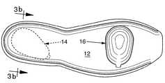
도 1은 본 발명에 따른 신발 밑창의 분해 사시도로서, 뒤꿈치 영역과 중족골 골두 영역에 배치된 공기 주머니를 보여주는 도면.1 is an exploded perspective view of a shoe sole according to the present invention, showing an air pocket disposed in the heel region and the metatarsal head region.
도 2a는 도 1에 도시된 밑창의 평면도로서, 중창의 발포 재료에 공기 주머니가 배치된 상태를 보여주는 도면.Figure 2a is a plan view of the sole shown in Figure 1, showing a state in which an air bag is placed on the foam material of the midsole.
도 2b는 공기 주머니가 특정한 반응을 제공하는 방위로 회전되어 있는 도 1 에 도시된 신발 밑창의 변형례의 평면도.FIG. 2B is a plan view of a variant of the shoe sole shown in FIG. 1 with the air pocket rotated in an orientation providing a specific response. FIG.
도 3a는 도 2a의 선 3A-3A를 따라 취한 단면도.3A is a cross sectional view taken along line 3A-3A in FIG. 2A;
도 3b는 도 2b의 선 3B-3B를 따라 취한 단면도.3B is a cross sectional view taken along line 3B-3B in FIG. 2B;
도 4는 도 2a의 선 4-4를 따라 취한 단면도.4 is a sectional view taken along line 4-4 of FIG. 2A;
도 5는 탑-로드(top-load) 형태로 도시된 뒷꿈치측 공기 주머니의 측면도.5 is a side view of the heel side air pocket shown in top-load form.
도 6은 도 5에 도시된 공기 주머니의 단부도.6 is an end view of the air bag shown in FIG.
도 7은 도 5에 도시된 공기 주머니의 저면도.FIG. 7 is a bottom view of the air pocket shown in FIG. 5. FIG.
도 8a는 도 7의 선 8-8을 따라 취한 단면도.8A is a sectional view taken along line 8-8 of FIG.
도 8b는 도 8a에 도시된 것과 유사한 단면도로서, 발에 충격이 가해지는 동안 강성이 원만하게 변화하는 것을 예시하는 중창의 발포 재료를 보여주는 도면.FIG. 8B is a cross-sectional view similar to that shown in FIG. 8A, showing the foam material of the midsole illustrating a smooth change in stiffness while impacting the foot;
도 9a는 도 7의 선 9-9를 따라 취한 단면도.9A is a sectional view taken along line 9-9 of FIG.
도 9b는 도 9a에 도시된 것과 유사한 단면도로서, 발에 충격이 가해지는 동안 강성이 원만하게 변화하는 것을 예시하는 중창의 발포 재료를 보여주는 도면.FIG. 9B is a cross-sectional view similar to that shown in FIG. 9A showing the midsole foam material illustrating a smooth change in stiffness while the foot is impacted;
도 10은 탑-로드 형태로 도시된 종골측 공기 주머니의 측면도.10 is a side view of the calcaneal side airbag shown in top-rod form;
도 11은 도 10에 도시된 공기 주머니의 단부도.FIG. 11 is an end view of the air bag shown in FIG. 10.
도 12는 도 10에 도시된 공기 주머니의 저면도.12 is a bottom view of the air pocket shown in FIG. 10.
도 13은 도 12의 선 13-13을 따라 취한 단면도.FIG. 13 is a sectional view taken along line 13-13 of FIG. 12;
도 14는 도 12의 선 14-14를 따라 취한 단면도.14 is a sectional view taken along line 14-14 of FIG.
도 15는 도 1에 도시된 충격 흡수 시스템과 신발 조립체의 다른 요소를 함께 보여주는 분해 조립도.FIG. 15 is an exploded view showing the shock absorbing system and other elements of the shoe assembly shown in FIG. 1 together; FIG.
도 16a는 본 발명에 따른 뒷꿈치 챔버의 다른 실시예의 분해 사시도.16A is an exploded perspective view of another embodiment of a heel chamber in accordance with the present invention.
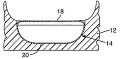
도 16b는 뒷꿈치 챔버가 밀봉된 상태에서 도 16a의 선 16B-16B를 따라 취한 단면도.FIG. 16B is a cross sectional view taken along
도 16c는 뒷꿈치 챔버가 밀봉된 상태에서 도 16a의 선 16C-16C를 따라 취한 단면도.16C is a cross sectional view taken along
도 17a는 밀봉 챔버에 힘이 가해지지 않을 때 박막의 인장과 내부압을 예시하는 밀봉 챔버의 모식적인 단면도.17A is a schematic cross-sectional view of the sealing chamber illustrating the tension and internal pressure of the thin film when no force is applied to the sealing chamber.
도 17b는 밀봉 챔버에 약간의 힘이 가해질 때 박막의 인장과 내부압을 예시하는 밀봉 챔버의 모식적인 단면도.17B is a schematic cross-sectional view of the sealing chamber illustrating the tension and internal pressure of the thin film when some force is applied to the sealing chamber.
도 17c는 증대된 힘이 밀봉 챔버에 가해질 때 박막의 인장과 내부압을 예시하는 밀봉 챔버의 모식적인 단면도.17C is a schematic cross-sectional view of the sealing chamber illustrating the tension and internal pressure of the thin film when increased force is applied to the sealing chamber.
도 17c는 밀봉 챔버에 큰 힘이 가해질 때 박막의 인장과 내부압을 예시하는 밀봉 챔버의 모식적인 단면도.17C is a schematic cross-sectional view of the sealing chamber illustrating the tension and internal pressure of the thin film when a large force is applied to the sealing chamber.
본 발명에 따른 밑창(10)은 엘라스토머 재료, 바람직하게는 탄성 발포 재료로 이루어진 중창(12)과, 이 중창에 배치되는 하나 이상의 공기 주머니(14, 16)를 포함한다. 도 1 내지 도 4는 뒷꿈치 영역에 배치된 공기 주머니(14)와, 중족골 골두 영역에 배치된 공기 주머니(16)를 구비하는 충격 흡수 시스템을 예시하는데, 여기서 상기 두 영역은 발에 충격이 가해지는 동안에 가장 큰 하중이 걸리는 영역이다. 이들 공기 주머니는 특정 형상의 밀봉 챔버를 형성하는 데 사용된다. 변형례 에서, 밀봉 챔버는 별도의 덮개 재료로 밀봉되어 있는 엘라스토머 챔버 내의 공간(void)으로 형성될 수 있다. 이들 챔버의 형상과 엘라스토머 재료 내에서, 특히 뒷꿈치 영역에서 그 배치는, 발의 충격의 초기에는 충격 흡수를 위해 크게 구부러지고, 그 후 발의 충격이 진행되는 동안 점진적으로 강성이 증대되는 바람직한 충격 흡수 특징을 제공한다.The sole 10 according to the invention comprises a
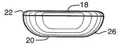
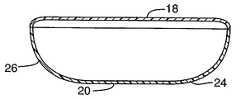
공기 주머니의 바람직한 형상은, 둥글고 테이퍼진 형상의 윤곽, 바람직하게는 도 5 내지 도 14에 잘 도시된 바와 같이 배 형상이다. 상기 형상은 착용자의 발바닥에 의해 가해지는 압력을 평가함으로써 결정된 것이다. 공기 주머니의 형상은 발의 압력 맵에 맞춰지는데, 압력이 클수록 공기 주머니 대 발포 재료의 깊이비도 커진다. 상기 윤곽의 형상은 서로 대향하고 거의 평행한 관계인 2개의 실질적으로 평탄한 주표면, 즉 제1 주표면(18)과 제2 주표면(20)으로 정해진다. 이들 주표면은 각각 경계부(22, 24)를 구비하는데, 이들 경계부는 공기 주머니(14)가 큰 둥근 단부(27)를 갖고 그보다 뾰족한 좁은 단부(29)로 테이퍼지도록 소정 형상의 공기 주머니를 형성한다. 상기 주표면(18, 20)이 거의 배 형상의 윤곽을 취하도록, 상기 좁은 단부(29)의 폭은 큰 둥근 단부(27)의 최대 폭에 비해 실질적으로 더 작다. 제2 주표면(20)은 제1 주표면(18)과 실질적으로 동일한 윤곽을 갖지만, 그 면적에 있어서는 약 50% 정도 더 작다. 공기 주머니의 둥근 단부(27)에서, 제1 주표면(18)과 제2 주표면(20)은 도 7 및 도 8에 도시된 바와 같이 단지 조금 한쪽으로 치우쳐 있다. 또한, 공기 주머니의 좁은 단부(29)에 있는 제2 주표면(20)의 지점은 둥근 단부에 있는 제1 주표면(18)의 대응 지점으로부터 이격되어 있다. 제1 주표면(18)과 제2 주표면(20)은 공기 주머니의 종방향 중심선(31)에 대해 대칭이다. 이들 주표면은 전체 공기 주머니 둘레로 연장되는 둥근 측벽(26)에 의해 서로 연결된다. 측벽(26)은 제1 주표면(18) 및 제2 주표면(20)과 일체로 형성되는 것이 바람직하고, 공기 주머니가 평평한 시트로 형성된 경우, 즉 진공 성형된 경우에는, 측벽(26)의 상당 부분이 제2 주표면(20)을 형성하는 시트와 동일한 시트로 형성된다. 취입 성형된 공기 주머니의 경우에도, 측벽이 제2 주표면과 마찬가지로 시임(seam)의 동일 측면에 형성된 것으로 보이도록, 시임이 배치된다.The preferred shape of the air bag is a round, tapered contour, preferably a pear shape as well shown in FIGS. 5 to 14. The shape is determined by evaluating the pressure exerted by the sole of the wearer. The shape of the air bag fits the pressure map of the foot, with the higher the pressure, the greater the depth ratio of the air bag to the foam material. The shape of the contour is defined by two substantially flat major surfaces, namely a first
도 7, 도 8a 및 도 9a에 잘 도시된 바와 같이, 제2 주표면(20)의 둥근 단부와 제1 주표면(18)의 둥근 단부 사이의 종방향 간격은, 제2 주표면(20)의 뾰족한 단부와 제1 주표면(18)의 뾰족한 단부 사이의 종방향 간격에 비해 짧다. 공기 주머니의 뾰족한 단부에는 길고 완만하게 경사진 윤곽이 마련되고 둥근 단부에는 짧고 완만하게 경사진 윤곽이 마련되도록, 상기 간격은 도 5 내지 도 9a에 잘 도시된 바와 측벽(26)에 의해 둥글게 덮인다. 그 결과, 제1 주표면(18)이 배치되는 실질적으로 평평한 측면과, 제2 주표면(20)이 배치되는 실질적으로 볼록한 측면을 구비하는 공기 주머니가 얻어진다. 공기 주머니(14)는 하나의 대칭 축선, 즉 종방향 축선을 갖고, 그 밖의 모든 양태에 있어서는 비대칭이다. 이와 같이 외관상 간단하고 확실하게 구분된 형상을 갖는 공기 주머니는, 하중에 대한 바람직한 충격 흡수 반응에 따라 다양하게 변형 가능하다. 또한, 도면에 도시된 바와 같이, 이들 주표면은 단지 측벽에 의해서만 서로 연결되어 있다. 이들 주표면에는 어떤 내부 연결도 없다.7, 8A and 9A, the longitudinal spacing between the rounded end of the second
도 1 내지 도 3b에 도시된 바와 같이, 발포 재료에서 공기 주머니의 방위는 다양한 충격 흡수 특성을 달성하도록 변경될 수 있다. 공기 주머니(14)는 그 종방향 축선이 도 2a에 도시된 바와 같이 중창의 종방향 축선과 거의 정렬되는 상태로, 탄성 발포 재료 내에 배향될 수 있으며, 그 결과 광범위한 착용자에 대해서 전체적인 충격 흡수 및 측방 지지를 제공할 것이다. 별법으로서, 공기 주머니(14)는 그 종방향 축선이 도 2b에 도시된 바와 같이 중창의 종방향 축선에 대해 중창의 측방면 방향으로 회전된 상태로 배향될 수 있다. 공기 주머니가 이러한 방식으로 회전되어 있는 경우, 발포 재료가 중창의 내측(medial side)에 보다 많이 존재하여 의사(擬似) 내측 포스트를 형성하므로, 발포 재료는 상기 내측 부분에서 하중에 대한 반응을 지배하고, 이로 인해 공기 주머니의 변형에 의해 지배되는 측방면에서의 반응보다 딱딱하게 느껴질 것이다. 발에 충격이 가해지는 동안에 밑창의 내측을 안정화시키고 지나친 내전(overpronation)을 억제하기 위해, 상기 내측에 지지부가 더 마련된다. 공기 주머니의 방위를 이러한 방식으로 조절함으로써, 충격 흡수 시스템의 반응 특징이 주문에 맞춰 조정될 수 있다. 도 2a 및 도 2b에 도시된 방위는 예로 주어진 것이며, 그 밖의 방위도 본 발명의 범위 내에 속하는 것으로 고려된다.As shown in Figures 1-3, the orientation of the air pockets in the foam material can be varied to achieve various shock absorbing properties. The
공기 주머니의 방위에 대한 다른 조절 방법으로는, 공기 주머니의 어느 측면이 위로 향하는 지를 결정하는 방법이 있다. 공기 주머니(14)가 탄성 발포 재료(12)에서 도 1 및 도 3a에 도시된 바와 같은 방위로 배치된 경우, 공기 주머니의 볼록한 측면이 발포 재료 내에 안착되고, 평평한 측면은 위로 향하게 되며 발포 재료에 의해 덮이지 않는다. 그에 의해, 보다 큰 충격 흡수가 제공되고, 즉 공기 주머니의 변형이 보다 크게 이루어지며, 하중이 걸릴 때에 공기 주머니의 느낌으로부터 보다 딱딱한 발포 재료의 느낌으로의 전환이 완만하게 이루어진다. 공기 주머니의 거의 평탄한 표면에 하중이 걸리는 도 3a에 도시된 방위는, 본원에서 탑-로드 조건(top loaded condition)이라 한다.Another way of adjusting the orientation of the air bag is to determine which side of the air bag is facing up. When the
제1 주표면(18)을 포함하는 실질적으로 평평한 측면을 아래로 향하게 하고 제2 주표면(20)을 포함하는 볼록한 측면을 위로 향하게 하여 공기 주머니 위에 있는 발포 재료가 하중을 받게 하도록, 공기 주머니(14)를 뒤집고 이를 발포 재료 내에서 배향할 수 있다(도 3b 참조). 이러한 방위는 본원에서 바텀-로드 조건(bottom loaded condition)이라 하는데, 이 조건에서는 발포 재료의 층이 공기 주머니의 볼록한 측면 위에 배치된다. 바텀-로드 조건은 탑-로드 조건에 비해 딱딱한 반응을 제공하는데, 이는 뒷꿈치와 공기 주머니 사이에 보다 많은 발포 재료가 존재하여 공기 주머니의 변형 느낌을 완화시키기 때문이다. 또한, 아치 구조가 형성된다. 그로 인해, 발에 충격이 가해지는 동안에 뒷꿈치 영역에 대하여 보다 강한 지지가 이루어진다.The air bag (with the first
이와 유사하게, 중창의 중족골 골두 영역에 있는 것으로 예시된 공기 주머니(16)도 그 방위에 따라 다양한 충격 흡수 특성을 제공할 수 있다. 또한, 공기 주머니(16)는 거의 평탄한 제1 주표면(28)과, 역시 거의 평탄하고 그 면적이 제1 주표면(28)보다 작은 제2 주표면(30)을 구비한다. 상기 제2 주표면의 표면적은 대략 제1 주표면의 표면적의 25 내지 40% 정도이다. 이들 주표면은 서로에 대해 거의 평행하고, 제1 경계부(32) 및 제2 경계부(34)에 의해 그 범위가 한정되며, 이들 경 계부는 공기 주머니(14)의 측벽(26)과 유사한 측벽(36)에 의해 연결된다. 제2 주표면(30)의 크기가 비교적 작기 때문에, 측벽은 비교적 평평한 경사를 갖고, 다시 말해서 공기 주머니가 탄성 발포 재료 내에 배치될 때, 공기 주머니로부터 발포 재료로의 반응 전환이 공기 주머니(16)의 경우에 매우 서서히 일어난다.Similarly, the
공기 주머니(16)는 탄성 발포 재료 내에 탑-로드 형태로 배치된 것으로 도시되어 있지만, 공기 주머니(14)의 경우와 마찬가지로 하중에 대하여 다양한 반응을 제공하도록 뒤집어질 수 있다. 도 2a에 도시된 바와 같이, 공기 주머니(16)의 종방향 축선이 착용자의 중족골 골두의 방향과 정렬되는 공기 주머니(16)의 방위는, 광범위한 착용자에 대해서 바람직한 충격 흡수 반응을 제공할 것이다. 그러나, 이러한 방위는 전술한 바와 같이 주문에 맞춰진 반응을 획득하도록 회전될 수 있다.The
도 2에 도시된 선 FS, 즉 발의 충격 라인 FS로 불리우는 것은, 달리기 스타일이 측방 뒷꿈치 영역에서의 발의 충격으로 시작되는 사람[리어 풋 스트라이커(rear foot striker)]이 달리는 동안에, 착용자의 발에 의해 신발의 밑창에 가해지는 최대 압력의 선을 예시한다. 선 FS는 상기 리어 풋 스트라이커의 경우에 최대 압력의 선이 따르는 방향을 일반화한 직선이다. 소정의 발의 충격에 대한 실제적인 압력선이 정확히 직선 FS를 따르는 것은 아니지만, 대체로 선 FS를 따른다. 도 2A에 도시된 바와 같이, 발의 충격의 선 FS는 측방 뒷꿈치 영역에서 시작되고, 뒷꿈치 영역을 지나 진행될 때 비스듬하게 전방을 향해 그리고 내측을 향해 진행되며(내전), 전방 뒷꿈치 및 아치 영역을 지나 보다 전방의 방향으로 나아가고, 끝으로 중족골, 중족골 골두 및 발끝 영역을 통해 진행되면서, 발은 제2 중족골 골두의 영 역 부근에서 지면을 떠난다(발끝이 지면에서 떨어짐).Called line FS, ie impact line FS of the foot, shown in FIG. 2, is defined by the wearer's foot while the person (rear foot striker) running, whose running style begins with the impact of the foot in the lateral heel area. Illustrate the line of maximum pressure applied to the sole of the shoe. Line FS is a straight line generalizing the direction which the line of maximum pressure follows in the case of the said rear foot striker. The actual pressure line for a given foot's impact does not exactly follow straight line FS, but generally follows line FS. As shown in FIG. 2A, the line FS of the impact of the foot begins in the lateral heel region, progresses obliquely forward and inwardly when advancing past the heel region (adduction), and passes through the anterior heel and arch regions. Proceeding forward and finally through the metatarsal, metatarsal head and toe regions, the foot leaves the ground near the area of the second metatarsal head (toe falls off the ground).
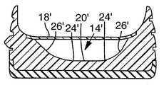
도 8a 및 도 9b는 착용자의 발이 뒷꿈치 영역에서 발의 전방을 향하는 발의 충격을 경험할 때, 중창의 발포 재료와 공기 주머니(14)의 형상이 어떻게 강성의 완만한 전환을 달성하는 가를 예시한다. 발의 충격의 초기에, 발은 후측방 뒷꿈치 영역, 즉 중창이 전부 발포 재료(F1)로 이루어져 견고하고 안정적이지만 충격을 흡수하는 영역에 접촉한다. 발의 충격이 내측으로 그리고 전방으로 진행될 때, 내측 영역(BSM)에 있는 완만한 경사의 윤곽으로 이루어진 측벽(26) 때문에, 발 아래에 있는 발포 재료(F2)의 양이 점차 줄어들고 공기 주머니(14)의 두께가 점차 증대된다. 이러한 영역에서, 공기 주머니의 최대 두께 영역 및 발포 재료의 최소 두께 영역(F3)에 이르기까지는, 보다 유연한 공기 주머니(14)의 영향으로 인하여 충격 흡수에 관한 효과가 점점 크게 나타나고 중창의 강성이 점차 줄어든다. 공기 주머니의 최대 두께는, 발의 종골측 아래에 있는 공기 주머니(14)의 측면 대 측면의 중심 영역(BC)에서 얻어진다. 이러한 방식에서, 공기 주머니(14)의 최대 변형, 최소 강성 및 최대 충격 감쇠는 종골측 아래에서 얻어진다.8A and 9B illustrate how the shape of the midsole's foam material and
발의 충격이 상기 중심 영역(BC)을 지나 내측으로 진행되므로, 측벽(26)은 완만한 윤곽, 즉 발포 재료(F4)의 두께가 점차 증대되어 공기 주머니(14)의 보다 유연한 효과로부터 발포 재료의 보다 딱딱하고 지지하는 효과로의 완만한 전환을 다시 제공하도록 공기 주머니의 측방면 영역(BSL)에서 공기 주머니(14)의 두께가 줄어드는 윤곽을 갖는다. 발의 충격이 전방 뒷꿈치 영역의 내측에 도달할 때, 발포 재료(F5)의 두께는 발표 재료의 최대 지지 효과를 제공하도록 전체 두께에 이르 게 된다. 도 2a와 도 2b의 비교에서 알 수 있듯이, 전방 뒷꿈치 영역의 내측에서 발포 재료의 지지 효과는, 공기 주머니(4)의 전방을 도 2b에 도시된 바와 같이 측방면을 향하게 함으로써 최대화될 수 있다. 이러한 배향에 의하면, 도 2a에 도시된 공기 주머니(14)에 비해 전방 뒷꿈치 영역의 내측에 보다 많은 발포 재료가 배치된다. 이러한 방위는 달리는 중에 지나친 내전을 억제하도록 되어 있는 신발에 바람직하다.Since the impact of the foot proceeds inwardly through the center area BC, the
또한, 공기 주머니의 효과로부터 발포 재료의 효과로의 완만한 전환은, 발의 충격이 후방 뒷꿈치 영역으로부터 발의 전방 영역을 향해 진행될 때 일어난다. 이러한 전환은, 공기 주머니의 전방 영역(BF)에 있는 공기 주머니(14)의 전방 측벽을 완만한 경사로 기울어지게 함으로써, 그리고 공기 주머니가 그 큰 둥근 단부(27)로부터 보다 뾰족한 좁은 단부(29)까지 연장될 때 공기 주머니(14)의 전체 두께가 줄어들게 함으로써, 상기 내측으로부터 측방으로의 전환과 유사한 방식으로 달성된다. 이러한 방식으로, 공기 주머니(14)의 전방에서 발포 재료가 전체 두께에 이르게 될 때까지, 공기 주머니(14)의 두께는 점차 줄어들고, 발포 재료(F6)의 두께는 점차 증대된다.In addition, a gentle transition from the effect of the air bag to the effect of the foam material occurs when the impact of the foot proceeds from the rear heel area toward the front area of the foot. This transition is made by tilting the front sidewall of the
충격 흡수 요소를 제조하는 다른 방법은, 테이퍼진 공기 주머니 형상의 공간을 갖고 이 공간을 밀봉하여 밀봉 챔버를 형성하도록, 탄성 재료, 예컨대 발포성 엘라스토머를 성형하는 것이다. 사출 성형, 주입 성형, 또는 압축 성형 등과 같은 임의의 통상적인 성형 기술이 사용될 수 있다. 에틸렌 비닐 아세테이트(EVA) 또는 폴리우레탄(PU) 등과 같은 임의의 성형 가능한 열가소성 엘라스토머가 사용될 수 있다. 이러한 다른 방법과, 발포 재료 내부의 밀봉 챔버에 관한 다른 구조가 도 16a, 도 16b 및 도 16c에 예시되어 있다. 발포성 엘라스토머가 공간을 제공하기 위한 인서트와 함께 성형되는 경우, 성형 공정 동안에 상기 인서트를 둘러싸는 발포 재료는 유동하고 외피를 형성할 것이다. 성형 공정의 종결 시에, 인서트는 제거되고, 이 인서트의 제거를 허용하는 개구는, 도 16a 내지 도 16c에 도시된 바와 같이, 예컨대 겉창(outsole), 라스팅 보드(lasting board), 또는 열가소성 우레탄 시트(19) 등과 같은 다른 탄성재 부재를 부착하는 것에 의해 밀봉된다. 상기 성형 공정으로부터 형성된 외피는, 별도의 공기 주머니를 필요로 하지 않으면서 상기 공기 주머니 재료와 유사한 작용을 하고, 상기 공간에 공기를 밀봉한다. 폐쇄형 셀 발포 재료가 사용된 경우, 외피 형성은 필요없을 것이다. 상기 밀봉 챔버는, 발포 재료에 의해 둘러싸이고 주변 공기로 채워진 공기 주머니가 갖는 충격 흡수 효과에 버금가는 충격 흡수 효과를 제공한다. 이러한 제조 방법은 공기 주머니 재료가 필요하지 않으므로 경제적이다. 또한, 별도의 공기 주머니를 형성하는 단계가 배제된다.Another method of manufacturing the shock absorbing element is to mold an elastic material, such as an expandable elastomer, to have a tapered air pocket shaped space and seal the space to form a sealed chamber. Any conventional molding technique can be used, such as injection molding, injection molding, or compression molding. Any moldable thermoplastic elastomer such as ethylene vinyl acetate (EVA) or polyurethane (PU) or the like can be used. These other methods and other structures relating to the sealing chamber inside the foam material are illustrated in FIGS. 16A, 16B and 16C. When the foamable elastomer is molded with an insert to provide space, the foam material surrounding the insert will flow and form a shell during the molding process. At the end of the molding process, the insert is removed and the opening allowing removal of the insert is, for example, an outsole, a lasting board, or a thermoplastic urethane sheet, as shown in FIGS. 16A-16C. Sealing by attaching another elastic member such as (19) or the like. The envelope formed from the molding process acts similar to the air bag material without requiring a separate air bag and seals the air in the space. If a closed cell foam material is used, skin formation will not be necessary. The sealing chamber provides a shock absorbing effect comparable to that of an air bag surrounded by foam material and filled with ambient air. This manufacturing method is economical since no air bag material is required. In addition, the step of forming a separate air bag is excluded.
도 16a 내지 도 16c에 도시된 바와 같이, 다른 밀봉 챔버(14')가 밑창(10')의 뒷꿈치 영역에 사용하기 위해 구성되어 있다. 공기 주머니(14)와 마찬가지로, 밀봉 챔버(14')는 둥글고 테이퍼진 형상을 갖고, 뒷꿈치 영역에서 발의 압력 맵에 맞게 배향되며, 압력이 클수록 공기 주머니 대 발포 재료의 깊이비가 커진다. 밀봉 챔버(14')는 서로에 대해 대향하고 거의 평행한 관계에 있는 2개의 실질적으로 평탄한 주표면, 즉 제1 주표면(18')과 제2 주표면(20')을 구비한다. 이들 주표면 은 각각 경계부(22', 24')를 구비하는데, 이들 경계부는 밀봉 챔버(14')가 제1 둥근 단부(27')를 구비하고 평탄한 단부(29')까지 약간 테이퍼지도록 밀봉 챔버의 형상을 한정한다. 둥근 측벽(26')이 각 경계부(22', 24') 사이에서 상기 주표면을 연결한다.As shown in FIGS. 16A-16C, another sealing
밀봉 챔버(14')는 공기 주머니(14)와 유사한 방식으로, 측방으로부터 내측 방향으로의 완만한 강성 전환과, 후방으로부터 전방으로의 완만한 강성 전환을 달성한다. 도 9b와 도 16c를 비교해 보면, 공기 주머니(14)와 마찬가지로 밀봉 챔버(14')의 내측과 측방 모두에 있어서 바닥 표면(24')으로부터 측벽(26')을 따르는 경사 윤곽이 유사한 것으로 도시되어 있다. 따라서, 충격이 뒷꿈치의 후측방 영역으로부터 진행되어 내측의 후방 영역을 향하여 이동하고, 전술한 바와 같이 강성의 원만한 전환이 달성된다. 경계부(22', 24')는 공기 주머니(14)의 경계부만큼 안쪽으로 테이퍼져 있지 않기 때문에, 밀봉 챔버(14')의 후방으로부터 전방으로 진행되는 원만한 강성의 전환은, 공기 주머니(14)와는 달리 바닥 표면(20')으로부터 전방을 향해 측벽(26')을 따르는 경사를 변화시키는 것에 의해 달성된다. 도 16b에 도시된 바와 같이, 밀봉 챔버(14')의 바닥은 바닥 표면(20')으로부터 측벽(26')을 지나는 구간에서 도 8b에 도시된 공기 주머니(14)의 바닥의 상향 테이퍼에 비해 더 큰 비율로 상향 전진 방향으로 테이퍼져 있다. 이와 같이 보다 급하게 상향으로 테이퍼지게 함으로써, 밀봉 챔버(14')의 협소화의 부족을 보상하여, 발의 충격이 적절한 점진율로 전방으로 이동할 때 밀봉 챔버 아래에 있는 발포 재료의 양을 증대시킨다.The sealing
강성은 공기 주머니의 방위를 조정하는 것에 의해 제어될 수 있다. 예컨대, 공기 주머니를 종골측 바로 아래에 탑-로드 형태로 배치하면, 공기 주머니가 종골측 아래에서 바텀-로드 형태로 배치되어 종골측과 공기 주머니 사이에 발포 재료가 있는 경우보다. 발에 충격이 가해지는 동안 초기에는 강성이 줄어들고, 그 이후에는 강성이 커진다. 전체적인 강성 반응은 주로 재료의 밀도 또는 경도에 의해 제어된다. 탑-로드 형태의 경우, 발포 재료의 밀도 또는 경도를 증대시키면 후반부에 강성이 증대된다. 바텀-로드 조건에서, 발포 재료의 밀도 또는 경도를 증대시키면 중반부 및 후반부의 강성이 증대된다. 또한, 강성의 경사는 체적에 의해 결정되고, 공기 주머니가 크면 강성이 낮으며 따라서 하중이 걸릴 때 더 많이 변위한다. 이는, 압축 중에 공기 주머니의 체적이 감소될 때 점진적 압력 증대를 허용하는 단일 챔버 내의 공기 체적이 더 크기 때문이다. 또한, 전체적인 강성은 보다 큰 제1 주표면(18, 18')의 크기를 변경하는 것에 의해 조정될 수 있다. 후술하는 바와 같이, 압력이 공기 주머니 또는 밀봉 챔버에 인가될 때, 노출되는 제1 주표면(18, 18')은 인장을 받는다. 제1 주표면(18, 18')의 면적이 증대되면, 표면이 받는 인장의 양이 감소되어, 강성도 또한 감소된다.Stiffness can be controlled by adjusting the orientation of the air bag. For example, if the air bag is placed in the form of a top-rod just below the calcaneal side, the air bag is arranged in the form of a bottom-rod below the calcaneal side than there is a foam material between the calcaneal side and the air bag. The stiffness initially decreases while the foot is impacted, and then increases. The overall stiffness reaction is mainly controlled by the density or hardness of the material. In the case of the top-rod form, increasing the density or hardness of the foam material increases the stiffness in the second half. In bottom-rod conditions, increasing the density or hardness of the foam material increases the stiffness of the mid and second half. In addition, the slope of the rigidity is determined by volume, and the larger the air bag, the lower the rigidity and thus the more the displacement is under load. This is because the volume of air in a single chamber is larger, which allows for gradual pressure increase when the volume of the air bag is reduced during compression. In addition, the overall stiffness can be adjusted by changing the size of the larger first
사용하기에 바람직한 발포 재료는, 비중 또는 밀도가 0.32 내지 0.40 그램/㎤, 바람직하게는 0.36 그램/㎤인 통상의 PU 발포 재료이다. 다른 바람직한 발포 재료는, 경도가 52 내지 60 Asker C, 바람직하게는 55 Asker C인 통상의 EVA이다. 별법으로서, 고형 엘라스토머가 유연하거나 유연해지게 된다면, 예컨대 우레탄 등의 고형 엘라스토머를 사용할 수 있다. 밑창 구조에 관한 다른 재료 특성으로는 엘라스토머 재료(탄성 계수)의 소정의 신장시에 있어서 인장 응력이 있다. 50% 신장시에 바람직한 인장 응력은 250 내지 1350 psi이다.Preferred foam materials for use are conventional PU foam materials having a specific gravity or density of 0.32 to 0.40 grams per cubic centimeter, preferably 0.36 grams per cubic centimeter. Another preferred foam material is conventional EVA having a hardness of 52 to 60 Asker C, preferably 55 Asker C. Alternatively, if the solid elastomer becomes flexible or flexible, solid elastomers such as urethane may be used. Another material property relating to the sole structure is tensile stress at a predetermined elongation of the elastomeric material (elastic modulus). Preferred tensile stress at 50% elongation is 250-1350 psi.
공기 주머니(14), 밀봉 챔버(14')가 중창의 뒷꿈치 영역 내에 설치되는 경우, 챔버의 개방 내부 체적이 약 10 내지 65 ㎤이면 적절한 충격 감쇠량이 제공된다. 이러한 공기 주머니의 경우, 실질적으로 평탄한 제1 주표면(18, 18')의 표면적은 약 1,200 내지 4,165 ㎟일 수 있다. 예컨대, 체적인 36 ㎤인 공기 주머니가 사용되는 경우, 공기 주머니(14)가 그 본래 체적의 95%까지 압축되면 압력 범위는 주변 압력인 0 psi 내지 35 psi이다.When the
본 발명에 따른 밑창 구조의 다른 장점은, 공기 주머니(14)가 박막 인장과 압력 램핑(ramping)의 조합에 의해 원만하게 그리고 점진적으로 딱딱해지는 방식에 있다. 또한, 주머니가 점진적으로 딱딱해지는 동안에 보다 큰 최대 변형을 허용하기 위해, 최대 압력의 면적 아래에 있는 구조를 최소화함으로써 충격 감쇠가 강화된다. 도 17a 내지 도 17d는 내부 연결부가 없는 챔버에 있어서 박막 인장과 압력 램핑을 예시한다.Another advantage of the sole structure according to the invention lies in the way in which the
도 17a는 엘라스토머 재료(13) 내에 있는 공기 주머니 또는 밀봉 챔버(14)를 모식적으로 예시한다. 공기 주머니(14)는 평탄한 제1 주표면(18)과 테이퍼진 측면을 갖는 제2 주표면(20)을 구비한다. 도 17a에서는, 공기 주머니에 압력이 인가되지 않고 제1 주표면(18)을 따라 걸리는 인장(T0)이 0이다. 이와 마찬가지로, 공기 주머니 내부 압력은 주변 압력이고, 참조를 위해 P0는 0으로서 나타낸다.FIG. 17A schematically illustrates an air bag or sealing
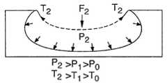
도 17b는 공기 주머니(16)에 인가되는 소량의 힘을 모시적으로 예시한다. 예컨대, 사람이 정지하여 서있고, 외력으로 표현된 외력 F1이 뒷꿈치의 종골에 의해 공기 주머니(14)에 인가된다. 도 17b에 도시된 바와 같이, 외력 F1은 제1 주표면(18)을 어느 정도 하향 만곡되게 하고, 공기 주머니(14) 내의 체적이 감소되며, 이로 인해 압력이 압력 P1으로 증대된다. 또한, 제1 주표면(18)이 활 모양으로 휘어지는 것에 의해, 제1 주표면(18)에서의 인장이 T1으로 증대된다. 이 도면에 예시되어 있지는 않지만, 외력 F1 - F3이 인가될 때 엘라스토머 재료(13)도 압축된다. 하향 외력에 의한 발포 재료(13)의 압축과 공기 주머니(16) 내의 압력 증대가 협력하여, 발포 재료의 벽을 안정화시키는데 기여한다.17B exemplarily illustrates a small amount of force applied to the
도 17c는 예컨대 걷는 동안에 공기 주머니(16)에 인가되는 종골측 외력 F2이 증가한 것을 모식적으로 예시한다. 여기에 도시된 바와 같이, 공기 주머니(16)의 체적은 더 줄어들고, 이로 인해 공기 주머니 내부의 압력이 P2로 증대되며, 주표면(18)을 따라 걸리는 인장이 T2로 증대된다.FIG. 17C schematically illustrates an increase in calcaneus external force F2 applied to
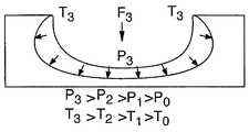
도 17d는 예컨대 달리는 동안에 공기 주머니(16)에 인가되는 최대 종골측 외력 F3을 예시한다. 여기에 도시된 바와 같이, 공기 주머니(16)의 체적은 상당히 감소되고, 이로 인해 공기 주머니 내부의 압력이 P3로 상당히 증대되며, 주표면(18)을 따라 걸리는 인장도 T3로 상당히 증대된다. 공기 주머니의 내부 영역은 내부 연결 부가 없고 공기로 채워져 있으므로, 공기 주머니는 도 17d에 도시된 바와 같이 상당 수준으로 압축될 수 있고, 이로 인해 공기 주머니의 충격 흡수 능력이 강화된다. 이와 같이 변형되는 동안에, 압력은 예컨대 P0(주변 압력)에서 P3(30 psi 이상)로 급상승한다. 공기 주머니 내부의 압력 증대는 공기 주머니의 측면을 따라 있는 발포 재료의 강성 증대와 함께, 밑창 바닥을 안정화하는데 기여한다. 따라서, 충격 흡수를 위한 최대 변형의 바람직한 목표치(내측의 측방 안정성도 함께 고려)는, 주변 압력에서 엘라스토머 재료 내부에서 적절한 형상을 갖는 공기 주머니를 함께 사용함으로써 달성된다.FIG. 17D illustrates, for example, the maximum calcaneal external force F3 applied to the
공기 주머니(14, 16)와 밀봉 챔버(14')는 모두 주변 공기를 수용하고, 주변 압력 또는 주변 압력 기준에서 5 psi(게이지 압력) 범위 내로 약간 상승된 압력으로 밀봉되도록 되어 있다. 이와 같이 낮은 수준으로 가압하거나 가압하지 않으면, 반복적이고 주기적인 하중에 대해서도 충분한 충격 흡수를 제공한다. 높은 수준의 가압이 요구되지 않기 때문에, 공기 주머니(14, 16)는 재료에 구애받지 않고, 그에 상응하게 질소 또는 육불화황 등과 같은 특수한 가스를 사용할 필요도 없으며, 또는 공기 주머니의 형성을 위해 특수한 차단 재료를 사용할 필요도 없다. 이와 같이, 특수한 재료 조건을 회피함으로써, 상당 수준의 비용 절감이 이뤄질뿐만 아니라 제조 공정도 간결화된다.The
배 모양 또는 테이퍼 형상이고 주변 압력 또는 이 주변 압력 기준에서 5 psi 범위 내로 밀봉되어 있는 공기 주머니의 방위와 배치를 변경하면, 주문에 맞춰진 다양한 충격 흡수 반응이 얻어질 수 있는 것으로 확인되었다.It has been found that varying the orientation and arrangement of the air bag, which is in the shape of a ship or tapered and sealed within the 5 psi range at ambient pressure or at this ambient pressure, can provide a variety of customized shock absorbing responses.
공기 주머니의 바람직한 제조 방법은 취입 성형과 진공 성형이다. 취입 성형은 다량의 일관된 물품을 경제적으로 생산하는 데 매우 적합한 잘 공지된 기술이다. 엘라스토머 재료의 튜브를 몰드 내에 넣고, 칼럼을 통해 공기를 공급하여 재료를 몰드에 맞닿게 압박한다. 취입 성형은, 눈에 띄지 않는 작은 시임을 갖고 깨끗하며 외관상 보기 좋은 물품을 생산한다. 그 밖의 많은 종래의 공기 주머니 제조 방법은 여러 제조 단계를 필요로 하고, 제조하기에 어렵고 생산하는데 많은 비용이 드는 구성 요소 및 재료를 필요로 한다. 일부 종래의 방법은, 외관상 보기에 좋지 않을 수 있는 눈에 띌 정도로 큰 시임을 그 주변에 형성한다. 진공 성형은 재료(바람직하게는 시트 형태)를 몰드에 넣고 몰드의 형상을 취하게 하는 점에서 취입 성형과 유사하지만, 공기를 몰드 안으로 도입하는 단계 이외에도, 공기를 밖으로 빼내어 차단 재료를 몰드의 측면을 향해 잡아당기는 단계를 포함하는 점이 다르다. 진공 성형은 대개 취입 성형에 사용되는 엘라스토머 재료의 바아, 튜브 또는 칼럼을 획득하는 데 드는 비용보다 더 저렴하게 획득 가능한 차단 재료의 평평한 시트로 실시될 수 있다. 통상의 열가소성 우레탄이 공기 주머니를 형성하는 데 사용될 수 있다. 그 밖의 적절한 재료로는 열가소성 엘라스토머, 폴리에스테르 폴리우레탄, 폴리에테르 폴리우레탄 등이 있다. 그 밖의 적절한 재료는 상기 '156 특허와 '945 특허에 개시되어 있다.Preferred methods of making air bags are blow molding and vacuum molding. Blow molding is a well known technique that is very suitable for economically producing large quantities of consistent articles. A tube of elastomeric material is placed in the mold and air is forced through the column to press the material against the mold. Blow molding produces a clean, apparently good article with an inconspicuous small seam. Many other conventional air bag manufacturing methods require several manufacturing steps and require components and materials that are difficult to manufacture and costly to produce. Some conventional methods form a noticeably large seam around it which may not be apparent in appearance. Vacuum molding is similar to blow molding in that the material (preferably in the form of a sheet) is placed in the mold and takes the shape of the mold, but in addition to the step of introducing air into the mold, the vacuum is drawn out to remove the barrier material from the sides of the mold. The difference is that it involves pulling towards. Vacuum forming can usually be carried out with a flat sheet of barrier material that is obtainable at less than the cost of obtaining a bar, tube or column of elastomeric material used in blow molding. Conventional thermoplastic urethanes can be used to form the air pockets. Other suitable materials include thermoplastic elastomers, polyester polyurethanes, polyether polyurethanes, and the like. Other suitable materials are disclosed in the '156 and' 945 patents above.
본 발명에 따른 충격 흡수 요소는, 도 15에서 신발 S에 조립되는 것으로 도시되어 있다. 충격 흡수 시스템(10)은 대개 신발의 상체(40)에 부착되는 라이너 (38)와, 신발의 지면에 닿는 부분인 겉창(42)과의 사이에 배치된다.The shock absorbing element according to the invention is shown as assembled in shoe S in FIG. 15. The
전술한 상세한 설명으로부터, 당업자의 영역 내에서 도출 가능한 본 발명의 변형예, 수정예 및 개조예가 많이 있다는 것은 명백할 것이다. 그러나, 본 발명의 정신으로부터 벗어나지 않는 이러한 모든 변형예는, 본원에 첨부된 청구범위에 의해서만 제한되는 본 발명의 범위 내에 있는 것으로 고려되도록 의도되어 있다.From the foregoing detailed description, it will be apparent that there are many variations, modifications and variations of the present invention which can be derived within the scope of those skilled in the art. However, all such modifications without departing from the spirit of the invention are intended to be considered within the scope of the invention, which is limited only by the claims appended hereto.
Claims (47)
Translated fromKoreanApplications Claiming Priority (3)
| Application Number | Priority Date | Filing Date | Title |
|---|---|---|---|
| US10/143,745 | 2002-05-09 | ||
| US10/143,745US6796056B2 (en) | 2002-05-09 | 2002-05-09 | Footwear sole component with a single sealed chamber |
| PCT/US2003/014399WO2003094645A1 (en) | 2002-05-09 | 2003-05-08 | Footwear sole component with a single sealed chamber |
Publications (2)
| Publication Number | Publication Date |
|---|---|
| KR20040111572A KR20040111572A (en) | 2004-12-31 |
| KR100753881B1true KR100753881B1 (en) | 2007-09-03 |
Family
ID=29400213
Family Applications (1)
| Application Number | Title | Priority Date | Filing Date |
|---|---|---|---|
| KR1020047017667AExpired - LifetimeKR100753881B1 (en) | 2002-05-09 | 2003-05-08 | Shoe sole element with single sealing chamber |
Country Status (9)
| Country | Link |
|---|---|
| US (3) | US6796056B2 (en) |
| EP (2) | EP1803365B1 (en) |
| KR (1) | KR100753881B1 (en) |
| CN (1) | CN100434005C (en) |
| AT (1) | ATE365476T1 (en) |
| AU (1) | AU2003230299A1 (en) |
| CA (1) | CA2483699C (en) |
| DE (1) | DE60314622T2 (en) |
| WO (1) | WO2003094645A1 (en) |
Cited By (2)
| Publication number | Priority date | Publication date | Assignee | Title |
|---|---|---|---|---|
| KR100976261B1 (en) | 2008-09-10 | 2010-08-18 | 김영식 | Shoe protector |
| KR101122543B1 (en)* | 2009-02-25 | 2012-06-28 | 전병우 | Air Cushion Footwear |
Families Citing this family (162)
| Publication number | Priority date | Publication date | Assignee | Title |
|---|---|---|---|---|
| US7426792B2 (en)* | 2002-05-09 | 2008-09-23 | Nike, Inc. | Footwear sole component with an insert |
| US7392604B2 (en)* | 2002-05-14 | 2008-07-01 | Nike, Inc. | System for modifying properties of an article of footwear |
| US9357812B2 (en) | 2002-08-19 | 2016-06-07 | APOS—Medical and Sports Technologies Ltd. | Proprioceptive/kinesthetic apparatus and method |
| US8758207B2 (en)* | 2002-08-19 | 2014-06-24 | APOS—Medical and Sports Technologies Ltd. | Proprioceptive/kinesthetic apparatus and method |
| US7707744B2 (en)* | 2003-07-16 | 2010-05-04 | Nike, Inc. | Footwear with a sole structure incorporating a lobed fluid-filled chamber |
| US7000335B2 (en)* | 2003-07-16 | 2006-02-21 | Nike, Inc. | Footwear with a sole structure incorporating a lobed fluid-filled chamber |
| US7707745B2 (en) | 2003-07-16 | 2010-05-04 | Nike, Inc. | Footwear with a sole structure incorporating a lobed fluid-filled chamber |
| US6931764B2 (en) | 2003-08-04 | 2005-08-23 | Nike, Inc. | Footwear sole structure incorporating a cushioning component |
| US7562469B2 (en)* | 2003-12-23 | 2009-07-21 | Nike, Inc. | Footwear with fluid-filled bladder and a reinforcing structure |
| US7086179B2 (en) | 2003-12-23 | 2006-08-08 | Nike, Inc. | Article of footwear having a fluid-filled bladder with a reinforcing structure |
| US7556846B2 (en) | 2003-12-23 | 2009-07-07 | Nike, Inc. | Fluid-filled bladder with a reinforcing structure |
| US7020990B2 (en)* | 2004-01-13 | 2006-04-04 | M. Steven Khoury | Orthopedic device for distributing pressure |
| US7222443B2 (en)* | 2004-03-11 | 2007-05-29 | Rocky Brands Wholesale Llc | Footwear with improved insole |
| US7334351B2 (en)* | 2004-06-07 | 2008-02-26 | Energy Management Athletics, Llc | Shoe apparatus with improved efficiency |
| DE102004033611A1 (en)* | 2004-07-12 | 2006-02-16 | Albert Schuhmann c/o. Euro-Kerze SP.Z.O.O. | Running and training shoe for e.g. sports, has upper and lower housings that are insertable into each other to form chamber, where parallel movement of upper housing with respect to lower housing enables module to release kinetic energy |
| DE102004045176B4 (en) | 2004-09-17 | 2011-07-21 | Adidas International Marketing B.V. | bladder |
| JP4843270B2 (en)* | 2004-12-24 | 2011-12-21 | グローブライド株式会社 | Battery device for fishing |
| KR100575466B1 (en)* | 2004-12-31 | 2006-05-03 | 박장원 | Cross-linked foam molded article for shoe insole with built-in shock absorber |
| KR100627143B1 (en)* | 2004-12-31 | 2006-09-25 | 박장원 | Cross-linked foamed molded article for three-dimensional shoe upper and manufacturing method thereof |
| KR100618385B1 (en)* | 2005-02-07 | 2006-08-30 | 박장원 | Method of manufacturing crosslinked foamed molded article for three-dimensional shoe upper |
| KR100618384B1 (en)* | 2005-02-07 | 2006-08-30 | 박장원 | Method of manufacturing crosslinked foamed molded article for three-dimensional shoe upper |
| KR100618383B1 (en)* | 2005-02-07 | 2006-08-30 | 박장원 | Method of manufacturing crosslinked foamed molded article for three-dimensional shoe upper |
| DE102005014709C5 (en) | 2005-03-31 | 2011-03-24 | Adidas International Marketing B.V. | shoe |
| WO2006129392A1 (en)* | 2005-05-30 | 2006-12-07 | Mizuno Corporation | Sole structure body for shoes |
| US20070023955A1 (en)* | 2005-07-27 | 2007-02-01 | Danny Ho | Footware cushioning method |
| US7464489B2 (en)* | 2005-07-27 | 2008-12-16 | Aci International | Footwear cushioning device |
| US7444767B2 (en)* | 2005-11-15 | 2008-11-04 | Nike, Inc. | Article of footwear with midsole having higher density peripheral portion |
| TW200806215A (en)* | 2006-03-30 | 2008-02-01 | Nelwood Corp | Shoe stability layer apparatus and method |
| US7607243B2 (en)* | 2006-05-03 | 2009-10-27 | Nike, Inc. | Athletic or other performance sensing systems |
| DE602006018717D1 (en)* | 2006-06-09 | 2011-01-20 | Johnson & Johnson Gmbh | Cushion pads for the human foot, insole and footwear with such a pad, and method of making such a sole |
| WO2008008960A1 (en)* | 2006-07-13 | 2008-01-17 | Biped Llc | Orthotic device for open shoes |
| USD594198S1 (en)* | 2007-07-11 | 2009-06-16 | Cheryl Kosmas | Orthotic device |
| US7810255B2 (en) | 2007-02-06 | 2010-10-12 | Nike, Inc. | Interlocking fluid-filled chambers for an article of footwear |
| US7950169B2 (en) | 2007-05-10 | 2011-05-31 | Nike, Inc. | Contoured fluid-filled chamber |
| US8819961B1 (en)* | 2007-06-29 | 2014-09-02 | Frampton E. Ellis | Sets of orthotic or other footwear inserts and/or soles with progressive corrections |
| US20090031583A1 (en)* | 2007-08-03 | 2009-02-05 | Schering-Plough Healthcare Products, Inc. | Foot Support For Alleviating Knee Pain |
| CN101795592A (en)* | 2007-09-06 | 2010-08-04 | 新平衡运动鞋公司 | Sole and shoe for midfoot touchdown person |
| US8490297B2 (en)* | 2007-10-11 | 2013-07-23 | Ginger Guerra | Integrated, cumulative-force-mitigating apparatus, system, and method for substantially-inclined shoes |
| US7895773B2 (en)* | 2007-11-06 | 2011-03-01 | Acushnet Company | Golf shoe |
| US8178022B2 (en) | 2007-12-17 | 2012-05-15 | Nike, Inc. | Method of manufacturing an article of footwear with a fluid-filled chamber |
| US8241450B2 (en) | 2007-12-17 | 2012-08-14 | Nike, Inc. | Method for inflating a fluid-filled chamber |
| US8863408B2 (en) | 2007-12-17 | 2014-10-21 | Nike, Inc. | Article of footwear having a sole structure with a fluid-filled chamber |
| US8341857B2 (en) | 2008-01-16 | 2013-01-01 | Nike, Inc. | Fluid-filled chamber with a reinforced surface |
| US8572867B2 (en)* | 2008-01-16 | 2013-11-05 | Nike, Inc. | Fluid-filled chamber with a reinforcing element |
| US20110214310A1 (en)* | 2008-01-31 | 2011-09-08 | Ori Rosenbaum | Shoe chassis |
| US8959798B2 (en) | 2008-06-11 | 2015-02-24 | Zurinvest Ag | Shoe sole element |
| EP2132999B1 (en)* | 2008-06-11 | 2015-10-28 | Zurinvest AG | Shoe sole element |
| EP2303049A1 (en)* | 2008-07-14 | 2011-04-06 | Prince Sports, Inc. | An improved sole structure |
| US8127469B2 (en)* | 2008-08-06 | 2012-03-06 | Quicksilver, Inc. | Footwear sole with a removable heel insert |
| US20100098797A1 (en)* | 2008-10-16 | 2010-04-22 | Davis Carrie L | Mold assembly for midsole and method of manufaturing same |
| US20120017467A1 (en)* | 2008-10-27 | 2012-01-26 | Temple University Of The Commonwealth System Of Higher Education | Orthotic shoe and insole assemblies |
| WO2010077296A2 (en) | 2008-12-09 | 2010-07-08 | Red Wing Shoe Company, Inc. | Molded insole for welted footwear |
| KR101121257B1 (en)* | 2009-04-02 | 2012-03-23 | 최철규 | Footwear Capable of Absorbing Cross Shock |
| US20100275468A1 (en)* | 2009-04-29 | 2010-11-04 | Brown Shoe Company, Inc. | Air circulating footbed and method thereof |
| US8209885B2 (en)* | 2009-05-11 | 2012-07-03 | Brooks Sports, Inc. | Shoe assembly with non-linear viscous liquid |
| US8650775B2 (en) | 2009-06-25 | 2014-02-18 | Nike, Inc. | Article of footwear having a sole structure with perimeter and central elements |
| US8166673B2 (en)* | 2009-07-10 | 2012-05-01 | Nike, Inc. | Air bladder footbed |
| WO2011017174A1 (en)* | 2009-08-03 | 2011-02-10 | Hbn Shoe, Llc | Footwear sole |
| US8246881B2 (en) | 2009-09-02 | 2012-08-21 | Nike, Inc. | Method of manufacturing sole assembly for article of footwear |
| US8845944B2 (en)* | 2009-09-02 | 2014-09-30 | Nike, Inc. | Method of manufacturing midsole for article of footwear |
| US8302329B2 (en) | 2009-11-18 | 2012-11-06 | Nike, Inc. | Footwear with counter-supplementing strap |
| US20110126422A1 (en)* | 2009-12-02 | 2011-06-02 | Brown Shoe Company, Inc. | Shoe sole with compressible protruding element |
| US9119439B2 (en) | 2009-12-03 | 2015-09-01 | Nike, Inc. | Fluid-filled structure |
| US8991072B2 (en)* | 2010-02-22 | 2015-03-31 | Nike, Inc. | Fluid-filled chamber incorporating a flexible plate |
| DE102010022329B4 (en) | 2010-06-01 | 2014-08-07 | Rolf Vogel | Insole and shoe |
| EP2588041A4 (en) | 2010-07-02 | 2016-06-01 | Apos Medical & Sports Technologies Ltd | DEVICE AND METHODS FOR ADJUSTING A SKELETAL MUSCLE |
| US8857077B2 (en) | 2010-09-30 | 2014-10-14 | Nike, Inc. | Footwear with internal harness |
| FR2967874B1 (en)* | 2010-11-29 | 2013-09-13 | Jean Luc Guer | SPORTS TYPE SPORTS SHOE |
| US9055784B2 (en) | 2011-01-06 | 2015-06-16 | Nike, Inc. | Article of footwear having a sole structure incorporating a plate and chamber |
| US8966788B2 (en)* | 2011-03-16 | 2015-03-03 | Yehushua BARAK | Set of podiatric articles |
| EP2564710B1 (en) | 2011-08-31 | 2014-10-22 | Rolf Vogel | Shoe insert and shoe |
| US9144265B2 (en) | 2011-09-14 | 2015-09-29 | Shoes For Crews, Llc | Shoe with support system |
| US9491984B2 (en) | 2011-12-23 | 2016-11-15 | Nike, Inc. | Article of footwear having an elevated plate sole structure |
| US9179733B2 (en) | 2011-12-23 | 2015-11-10 | Nike, Inc. | Article of footwear having an elevated plate sole structure |
| US9750300B2 (en) | 2011-12-23 | 2017-09-05 | Nike, Inc. | Article of footwear having an elevated plate sole structure |
| US10201210B2 (en) | 2012-03-22 | 2019-02-12 | Nike, Inc. | Restraint configured to allow relative heel/forefoot motion |
| US9936759B2 (en) | 2012-03-22 | 2018-04-10 | Nike, Inc. | Footwear and foot support member configured to allow relative heel/forefoot motion |
| DE102012206094B4 (en)* | 2012-04-13 | 2019-12-05 | Adidas Ag | Soles for sports footwear, shoes and method of making a shoe sole |
| US20130312292A1 (en)* | 2012-05-22 | 2013-11-28 | Sark Ltd. | Sole for a shoe and related methods |
| US10856612B2 (en) | 2012-09-20 | 2020-12-08 | Nike, Inc. | Sole structures and articles of footwear having plate moderated fluid-filled bladders and/or foam type impact force attenuation members |
| US10849387B2 (en) | 2012-09-20 | 2020-12-01 | Nike, Inc. | Sole structures and articles of footwear having plate moderated fluid-filled bladders and/or foam type impact force attenuation members |
| USD699930S1 (en)* | 2012-11-28 | 2014-02-25 | Slotflop Ventures | Sandal sole |
| US9380832B2 (en) | 2012-12-20 | 2016-07-05 | Nike, Inc. | Article of footwear with fluid-filled chamber lacking an inflation channel and method for making the same |
| US9872535B2 (en)* | 2012-12-20 | 2018-01-23 | Nike, Inc. | Article of footwear with a harness and fluid-filled chamber arrangement |
| US9179737B2 (en) | 2013-01-31 | 2015-11-10 | Nike, Inc. | Sole assembly with plural portions that cooperatively define chamber |
| US9743711B2 (en) | 2013-01-31 | 2017-08-29 | Nike, Inc. | Sole assembly with plural portions that cooperatively define chamber |
| US9930928B2 (en) | 2013-02-13 | 2018-04-03 | Adidas Ag | Sole for a shoe |
| DE102013002519B4 (en) | 2013-02-13 | 2016-08-18 | Adidas Ag | Production method for damping elements for sportswear |
| US9610746B2 (en) | 2013-02-13 | 2017-04-04 | Adidas Ag | Methods for manufacturing cushioning elements for sports apparel |
| DE102013202291B4 (en) | 2013-02-13 | 2020-06-18 | Adidas Ag | Damping element for sportswear and shoes with such a damping element |
| DE102013202306B4 (en) | 2013-02-13 | 2014-12-18 | Adidas Ag | Sole for a shoe |
| US9603410B2 (en) | 2013-02-13 | 2017-03-28 | Flop Girl, Llc | Modular shoe with interchangeable components and method of attachment |
| DE102013202485B4 (en) | 2013-02-15 | 2022-12-29 | Adidas Ag | Ball for a ball sport |
| US10806214B2 (en)* | 2013-03-08 | 2020-10-20 | Nike, Inc. | Footwear fluid-filled chamber having central tensile feature |
| TWM460545U (en)* | 2013-04-09 | 2013-09-01 | Taiwell Technology Co Ltd | Foot arch insole structure having elastic liquid body |
| USD787167S1 (en) | 2013-04-10 | 2017-05-23 | Frampton E. Ellis | Footwear sole |
| USD731766S1 (en)* | 2013-04-10 | 2015-06-16 | Frampton E. Ellis | Footwear sole |
| USD740004S1 (en) | 2013-04-12 | 2015-10-06 | Adidas Ag | Shoe |
| USD776410S1 (en) | 2013-04-12 | 2017-01-17 | Adidas Ag | Shoe |
| CN104665078B (en)* | 2013-11-26 | 2016-10-05 | 李伯曜 | sports shoes |
| US20150289591A1 (en)* | 2014-04-09 | 2015-10-15 | Nike, Inc. | Modular Articles With Customizable Sole Inserts |
| US20150289590A1 (en)* | 2014-04-09 | 2015-10-15 | Nike, Inc. | Footwear System With Removable Inserts |
| KR101430135B1 (en) | 2014-04-10 | 2014-08-13 | 이승하 | Footwear sole for cushioning and shock-absorbing |
| DE102014215897B4 (en) | 2014-08-11 | 2016-12-22 | Adidas Ag | adistar boost |
| DE102014216115B4 (en) | 2014-08-13 | 2022-03-31 | Adidas Ag | 3D elements cast together |
| WO2016032894A1 (en) | 2014-08-29 | 2016-03-03 | Nike Innovate C.V. | Sole assembly for an article of footwear with bowed spring plate |
| US9516919B2 (en) | 2014-09-16 | 2016-12-13 | Nike, Inc. | Sole structure with bladder for article of footwear and method of manufacturing the same |
| CN104352026B (en)* | 2014-11-06 | 2016-08-24 | 际华三五一五皮革皮鞋有限公司 | A kind of composite functional shoe pad and technology of preparing thereof |
| JP6622467B2 (en)* | 2015-02-20 | 2019-12-18 | ダイヤテックス株式会社 | Sole structure and shoes |
| EP3280283B1 (en) | 2015-04-08 | 2020-05-06 | NIKE Innovate C.V. | Article with overlay secured to bladder element over image and method of manufacturing the article |
| WO2016164549A1 (en) | 2015-04-08 | 2016-10-13 | Nike Innovate C.V. | Article including a bladder element with an image and method of manufacturing the article |
| US9854870B2 (en) | 2015-04-08 | 2018-01-02 | Nike, Inc. | Method of manufacturing a bladder element with an impression of etched area of mold assembly and article having bladder element with impression |
| CN107427101B (en) | 2015-04-08 | 2021-08-17 | 耐克创新有限合伙公司 | Method of making a capsule element with etched features and article having a capsule element with etched features |
| DE102015206486B4 (en) | 2015-04-10 | 2023-06-01 | Adidas Ag | Shoe, in particular sports shoe, and method for manufacturing the same |
| DE102015206900B4 (en) | 2015-04-16 | 2023-07-27 | Adidas Ag | sports shoe |
| US20160302517A1 (en)* | 2015-04-17 | 2016-10-20 | Wolverine World Wide, Inc. | Sole assembly for an article of footwear |
| USD785302S1 (en)* | 2015-04-20 | 2017-05-02 | Dean Karnazes | Instability footwear sole |
| DE102015209795B4 (en) | 2015-05-28 | 2024-03-21 | Adidas Ag | Ball and process for its production |
| USD783264S1 (en) | 2015-09-15 | 2017-04-11 | Adidas Ag | Shoe |
| US10292378B2 (en)* | 2015-12-17 | 2019-05-21 | Monty L. Ruetenik | Adjustable equine boot rocker attachment |
| US10856610B2 (en) | 2016-01-15 | 2020-12-08 | Hoe-Phuan Ng | Manual and dynamic shoe comfortness adjustment methods |
| AU2017235417B2 (en)* | 2016-03-15 | 2019-06-27 | Nike Innovate C.V. | Sole structure for article of footwear |
| CN115944143A (en)* | 2016-07-20 | 2023-04-11 | 耐克创新有限合伙公司 | Shoe plate |
| USD840136S1 (en) | 2016-08-03 | 2019-02-12 | Adidas Ag | Shoe midsole |
| USD840137S1 (en) | 2016-08-03 | 2019-02-12 | Adidas Ag | Shoe midsole |
| USD852475S1 (en) | 2016-08-17 | 2019-07-02 | Adidas Ag | Shoe |
| JP1582717S (en) | 2016-09-02 | 2017-07-31 | ||
| KR101799947B1 (en) | 2016-12-08 | 2017-11-21 | 감병욱 | Front high-heeled shoes |
| KR102206248B1 (en) | 2017-02-01 | 2021-01-22 | 나이키 이노베이트 씨.브이. | Stacked cushioning arrangement for sole structure |
| USD816962S1 (en) | 2017-06-30 | 2018-05-08 | Frampton E. Ellis | Footwear sole |
| CN107157010B (en)* | 2017-07-13 | 2024-05-17 | 三六一度(中国)有限公司 | Sole component and shoe with same |
| USD837497S1 (en) | 2017-07-14 | 2019-01-08 | Anatomic Research, Inc. | Footwear sole |
| USD838090S1 (en) | 2017-07-14 | 2019-01-15 | Anatomic Research, Inc. | Footwear sole |
| USD899061S1 (en) | 2017-10-05 | 2020-10-20 | Adidas Ag | Shoe |
| USD838088S1 (en) | 2017-12-06 | 2019-01-15 | Anatomic Research, Inc. | Athletic sandal |
| USD845592S1 (en) | 2017-12-07 | 2019-04-16 | Anatomic Research, Inc. | Sandal |
| USD840645S1 (en) | 2018-02-06 | 2019-02-19 | Anatomic Research, Inc. | Athletic sandal upper |
| USD844304S1 (en) | 2018-02-06 | 2019-04-02 | Anatomic Research, Inc. | Athletic sandal upper |
| USD841953S1 (en) | 2018-02-06 | 2019-03-05 | Anatomic Research, Inc. | Footwear sole |
| CN112087964B (en)* | 2018-05-30 | 2022-08-02 | 耐克创新有限合伙公司 | Footwear sole structure with bladder |
| USD863739S1 (en) | 2018-08-21 | 2019-10-22 | Anatomic Research, Inc. | Athletic sandal sole |
| EP3883771A1 (en)* | 2018-11-20 | 2021-09-29 | Ecco Sko A/S | A 3d printed structure |
| TWI722634B (en) | 2018-11-30 | 2021-03-21 | 荷蘭商耐克創新有限合夥公司 | Article of footwear and method of manufacturing an article of footwear |
| DE102019204579B4 (en) | 2019-04-01 | 2022-10-06 | Adidas Ag | Recycling a shoe |
| USD909726S1 (en)* | 2019-04-26 | 2021-02-09 | Foot Care Store Inc. | Footwear sole |
| EP3975786A1 (en)* | 2019-05-30 | 2022-04-06 | NIKE Innovate C.V. | Sole structure for an article of footwear |
| US11666118B2 (en)* | 2019-11-19 | 2023-06-06 | Nike, Inc. | Bladder and sole structure for article of footwear |
| JP2020022896A (en)* | 2019-11-22 | 2020-02-13 | ダイヤテックス株式会社 | Sole structure and shoe |
| US12064006B2 (en)* | 2019-12-30 | 2024-08-20 | Nike, Inc. | Airbag for article of footwear |
| US11766092B2 (en)* | 2020-02-21 | 2023-09-26 | Nike, Inc. | Sole structure for article of footwear |
| US11839260B2 (en)* | 2020-05-11 | 2023-12-12 | Nike, Inc. | Sole structure for article of footwear |
| USD921337S1 (en) | 2020-07-16 | 2021-06-08 | Anatomic Research, Inc. | Athletic sandal |
| US20220225731A1 (en)* | 2020-08-03 | 2022-07-21 | Hafia Salum Mkumba | Footwear midsole comprising a support and one or more internal bladders |
| IT202000022600A1 (en)* | 2020-09-24 | 2022-03-24 | Vibram Spa | SOLE FOR SPORTS SHOES |
| CN113197387B (en)* | 2021-05-19 | 2024-02-13 | 长春工程学院 | Centripetal shrinkage gasbag sports shoes |
| USD988660S1 (en) | 2021-07-27 | 2023-06-13 | Frampton E. Ellis | Lateral side extension for the midfoot of a shoe sole |
| USD973314S1 (en) | 2021-08-04 | 2022-12-27 | Anatomic Research, Inc. | Athletic sandal |
| US20230127595A1 (en)* | 2021-10-25 | 2023-04-27 | Nike, Inc. | Sole structure for article of footwear |
| USD1003012S1 (en) | 2022-02-04 | 2023-10-31 | Anatomic Research, Inc. | Athletic sandal |
| US20240180291A1 (en)* | 2022-12-05 | 2024-06-06 | Reebok International Limited | Article of footwear having a reflectively symmetrical fluid cushioning system |
| KR102692078B1 (en)* | 2023-12-19 | 2024-08-05 | 조휘준 | An functional insole for preventing of turtle neck symdrome and fall-down |
| US12369685B1 (en) | 2024-06-12 | 2025-07-29 | 1158990 B.C. Ltd. | Shoe midsole with delayed energy return and lateral shear stability |
Citations (2)
| Publication number | Priority date | Publication date | Assignee | Title |
|---|---|---|---|---|
| US3724106A (en) | 1971-06-29 | 1973-04-03 | H Magidson | Insole structure |
| JP2003007532A (en)* | 2001-06-18 | 2003-01-10 | Hitachi Unisia Automotive Ltd | Engine valve electromagnetic drive |
Family Cites Families (90)
| Publication number | Priority date | Publication date | Assignee | Title |
|---|---|---|---|---|
| US1193608A (en)* | 1916-08-08 | Insole | ||
| GB189414955A (en) | 1894-08-04 | 1895-06-08 | William Seaton Mclennan | Improvements in Rocking Chairs. |
| US1240153A (en) | 1916-01-07 | 1917-09-11 | Keene Shock Absorber Company | Pneumatic cushion for shoes. |
| DE352216C (en) | 1921-07-19 | 1922-04-24 | Alwin Baerschneider | Footwear with a bladder filled with compressed air inserted between two soles |
| US2086389A (en) | 1936-09-24 | 1937-07-06 | Pearson Susan Clare | Inflated arch support and ventilated heel cushion |
| US2365807A (en) | 1943-04-17 | 1944-12-26 | Emmanuel M Dialynas | Pneumatic or cushion arch support for shoes |
| US2488382A (en) | 1946-06-07 | 1949-11-15 | Whitman W Davis | Pneumatic foot support |
| US2605560A (en)* | 1950-07-31 | 1952-08-05 | Gouabault Robert | Shoe sole |
| US2762134A (en) | 1954-07-30 | 1956-09-11 | Edward W Town | Cushioning insoles for shoes |
| FR1406610A (en) | 1964-06-10 | 1965-07-23 | Perfected shoe | |
| US3469578A (en)* | 1965-10-12 | 1969-09-30 | Howard R Bierman | Infusion device for ambulatory patients with flow control means |
| US3469576A (en) | 1966-10-05 | 1969-09-30 | Henry M Smith | Footwear |
| US4017931A (en) | 1976-05-20 | 1977-04-19 | The Jonathan-Alan Corporation | Liquid filled insoles |
| US4115934A (en) | 1977-02-11 | 1978-09-26 | Hall John M | Liquid shoe innersole |
| FR2407008A1 (en) | 1977-10-28 | 1979-05-25 | Bataille Jean Roger | DYNAMIC FOOT AND LEG TIMING PACKAGE IN A RIGID PACKAGE |
| US4370754A (en) | 1978-07-27 | 1983-02-01 | American Pneumatics Co. | Variable pressure pad |
| US4297797A (en) | 1978-12-18 | 1981-11-03 | Meyers Stuart R | Therapeutic shoe |
| US4445283A (en) | 1978-12-18 | 1984-05-01 | Synapco Ltd. | Footwear sole member |
| IT7960923U1 (en)* | 1979-06-07 | 1980-12-07 | Garzia Carmine | INSOLE FOR FOOTWEAR AND SIMILAR EQUIPPED WITH SEVERAL PARTIALLY COMMUNICATING AIR CHAMBERS DESIGNED TO DISTRIBUTE PRESSURE ACROSS THE ENTIRE SOLE OF THE FOOT |
| US4453271A (en) | 1979-09-28 | 1984-06-12 | American Pneumatics Co. | Protective garment |
| US4358902A (en) | 1980-04-02 | 1982-11-16 | Cole George S | Thrust producing shoe sole and heel |
| DE3147589A1 (en) | 1981-12-01 | 1983-06-09 | Konsumex Külkereskedelmi Vállalat, 1146 Budapest | "SELF-ADJUSTING ORTHOPEDIC SHOE INSERT AND / OR FLAT FOOT INSERT" |
| US4486901A (en) | 1982-03-12 | 1984-12-11 | Houston Protective Equipment, Inc. | Multi-layered, open-celled foam shock absorbing structure for athletic equipment |
| US4446634A (en) | 1982-09-28 | 1984-05-08 | Johnson Paul H | Footwear having improved shock absorption |
| DE3237235C2 (en)* | 1982-10-07 | 1986-07-10 | Wacker-Chemitronic Gesellschaft für Elektronik-Grundstoffe mbH, 8263 Burghausen | Process for polishing III-V semiconductor surfaces |
| US4494321A (en)* | 1982-11-15 | 1985-01-22 | Kevin Lawlor | Shock resistant shoe sole |
| US4441211A (en) | 1983-03-25 | 1984-04-10 | Houston Protective Equipment, Inc. | Protective batting jacket |
| US4513449A (en) | 1983-03-25 | 1985-04-30 | Donzis Byron A | Shock absorbing athletic equipment |
| US4535553A (en) | 1983-09-12 | 1985-08-20 | Nike, Inc. | Shock absorbing sole layer |
| US4577417A (en)* | 1984-04-27 | 1986-03-25 | Energaire Corporation | Sole-and-heel structure having premolded bulges |
| US4670995A (en) | 1985-03-13 | 1987-06-09 | Huang Ing Chung | Air cushion shoe sole |
| US4803029A (en) | 1986-01-28 | 1989-02-07 | Pmt Corporation | Process for manufacturing an expandable member |
| US5199191A (en) | 1987-05-29 | 1993-04-06 | Armenak Moumdjian | Athletic shoe with inflatable mobile inner sole |
| US4779359A (en) | 1987-07-30 | 1988-10-25 | Famolare, Inc. | Shoe construction with air cushioning |
| US6425195B1 (en) | 1987-09-21 | 2002-07-30 | Byron A. Donzis | Impact absorbing composites and their production |
| US5235715A (en) | 1987-09-21 | 1993-08-17 | Donzis Byron A | Impact asborbing composites and their production |
| US4874640A (en) | 1987-09-21 | 1989-10-17 | Donzis Byron A | Impact absorbing composites and their production |
| US5083361A (en) | 1988-02-05 | 1992-01-28 | Robert C. Bogert | Pressurizable envelope and method |
| MY106949A (en) | 1988-02-05 | 1995-08-30 | Rudy Marion F | Pressurizable envelope and method |
| US4906502A (en) | 1988-02-05 | 1990-03-06 | Robert C. Bogert | Pressurizable envelope and method |
| CA1338369C (en)* | 1988-02-24 | 1996-06-11 | Jean-Pierre Vermeulen | Shock absorbing system for footwear application |
| US5042176A (en) | 1989-01-19 | 1991-08-27 | Robert C. Bogert | Load carrying cushioning device with improved barrier material for control of diffusion pumping |
| US4936029A (en) | 1989-01-19 | 1990-06-26 | R. C. Bogert | Load carrying cushioning device with improved barrier material for control of diffusion pumping |
| US5253435A (en) | 1989-03-17 | 1993-10-19 | Nike, Inc. | Pressure-adjustable shoe bladder assembly |
| USD328159S (en) | 1989-06-06 | 1992-07-21 | Donzis Laboratories, Inc. | Body pad |
| JPH05503865A (en) | 1990-02-16 | 1993-06-24 | トレトルン アクティエボラーグ | stability shoe device |
| US5245766A (en) | 1990-03-30 | 1993-09-21 | Nike, Inc. | Improved cushioned shoe sole construction |
| US5224277A (en) | 1990-05-22 | 1993-07-06 | Kim Sang Do | Footwear sole providing ventilation, shock absorption and fashion |
| DE4035416A1 (en) | 1990-11-07 | 1992-05-14 | Adidas Ag | SHOE BASE, ESPECIALLY FOR SPORTSHOES |
| US5179792A (en) | 1991-04-05 | 1993-01-19 | Brantingham Charles R | Shoe sole with randomly varying support pattern |
| US5353523A (en) | 1991-08-02 | 1994-10-11 | Nike, Inc. | Shoe with an improved midsole |
| US5406719A (en) | 1991-11-01 | 1995-04-18 | Nike, Inc. | Shoe having adjustable cushioning system |
| CN1073339A (en)* | 1991-12-17 | 1993-06-23 | 金相道 | The fangle sole of ventilation and damping |
| DE4200041A1 (en)* | 1992-01-02 | 1993-08-05 | Kneissl Dachstein Sportartikel | OUTSOLE, ESPECIALLY FOR A HIKING OR MOUNTAIN SHOE |
| US5224278A (en) | 1992-09-18 | 1993-07-06 | Jeon Pil D | Midsole having a shock absorbing air bag |
| US5685090A (en)* | 1993-03-26 | 1997-11-11 | Nike, Inc. | Cushioning system for shoe sole and method for making the sole |
| US5625964A (en) | 1993-03-29 | 1997-05-06 | Nike, Inc. | Athletic shoe with rearfoot strike zone |
| US5881395A (en) | 1993-07-08 | 1999-03-16 | Donzis; Byron A | Impact absorbing pad |
| US5353459A (en) | 1993-09-01 | 1994-10-11 | Nike, Inc. | Method for inflating a bladder |
| US5771606A (en) | 1994-10-14 | 1998-06-30 | Reebok International Ltd. | Support and cushioning system for an article of footwear |
| CA2181998C (en) | 1994-01-26 | 2003-05-13 | Paul E. Litchfield | Cushioning member for an article of footwear |
| US5595004A (en) | 1994-03-30 | 1997-01-21 | Nike, Inc. | Shoe sole including a peripherally-disposed cushioning bladder |
| US5952065A (en) | 1994-08-31 | 1999-09-14 | Nike, Inc. | Cushioning device with improved flexible barrier membrane |
| US6505420B1 (en)* | 1996-02-09 | 2003-01-14 | Reebok International Ltd. | Cushioning member for an article of footwear |
| US6266897B1 (en)* | 1994-10-21 | 2001-07-31 | Adidas International B.V. | Ground-contacting systems having 3D deformation elements for use in footwear |
| AU4365396A (en) | 1994-12-02 | 1996-06-19 | Nike International Ltd. | Cushioning device for a footwear sole and method for making the same |
| US5638612A (en) | 1995-03-10 | 1997-06-17 | Donzis; Byron A. | Impact absorbing system for footwear |
| US6013340A (en) | 1995-06-07 | 2000-01-11 | Nike, Inc. | Membranes of polyurethane based materials including polyester polyols |
| IT1281968B1 (en) | 1995-07-14 | 1998-03-06 | Diadora Spa | COMPOSITE STRUCTURE OF MIDSOLE |
| US5741568A (en) | 1995-08-18 | 1998-04-21 | Robert C. Bogert | Shock absorbing cushion |
| US5653046A (en)* | 1995-09-06 | 1997-08-05 | Lawlor; Kevin B. | Durable, lightweight shock resistant shoe sole |
| US5918383A (en)* | 1995-10-16 | 1999-07-06 | Fila U.S.A., Inc. | Sports shoe having an elastic insert |
| US5704137A (en) | 1995-12-22 | 1998-01-06 | Brooks Sports, Inc. | Shoe having hydrodynamic pad |
| US5701687A (en)* | 1996-01-02 | 1997-12-30 | Energaire Corporation | Thrust producing sole and heel structure with interior and exterior fluid filled pockets |
| US6175967B1 (en) | 1996-02-02 | 2001-01-23 | Byron A. Donzis | Air fit protective system |
| US5813142A (en) | 1996-02-09 | 1998-09-29 | Demon; Ronald S. | Shoe sole with an adjustable support pattern |
| US5794275A (en) | 1996-02-09 | 1998-08-18 | Donzis; Byron A. | Impact absorbing shield for protective gear |
| US5706589A (en)* | 1996-06-13 | 1998-01-13 | Marc; Michel | Energy managing shoe sole construction |
| TW320555B (en) | 1996-06-15 | 1997-11-21 | Ing-Jiunn Hwang | The 3D shoes-tongue cushion |
| TW318139B (en) | 1996-06-15 | 1997-10-21 | Ing-Jiunn Hwang | Parent-and-child air cushion for buffer |
| US5890683A (en)* | 1997-02-13 | 1999-04-06 | Diebold, Incorporated | Tube hanger |
| US5894687A (en)* | 1997-06-18 | 1999-04-20 | Gnan-Jang Plastics Co., Ltd. | Shoe pad having massaging effect |
| US5993585A (en) | 1998-01-09 | 1999-11-30 | Nike, Inc. | Resilient bladder for use in footwear and method of making the bladder |
| US5894683A (en)* | 1998-01-23 | 1999-04-20 | Gnan-Jang Plastics Co., Ltd. | Shock absorbing heel block for shoes |
| US6009637A (en)* | 1998-03-02 | 2000-01-04 | Pavone; Luigi Alessio | Helium footwear sole |
| US5956869A (en)* | 1998-03-06 | 1999-09-28 | Energaire Corporation | Shoe sole construction with mesh liner for mid-sole cavity |
| US6176025B1 (en) | 1999-05-28 | 2001-01-23 | Spalding Sports Worldwide, Inc. | Cushioning system for golf shoes |
| US6510624B1 (en)* | 1999-09-10 | 2003-01-28 | Nikola Lakic | Inflatable lining for footwear with protective and comfortable coatings or surrounds |
| AU5920199A (en) | 1999-09-16 | 2001-04-17 | Andrew A. Bjornson | Support and cushioning system for an article of footwear |
| US6374514B1 (en)* | 2000-03-16 | 2002-04-23 | Nike, Inc. | Footwear having a bladder with support members |
- 2002
- 2002-05-09USUS10/143,745patent/US6796056B2/ennot_activeExpired - Lifetime
- 2003
- 2003-05-08ATAT03724505Tpatent/ATE365476T1/ennot_activeIP Right Cessation
- 2003-05-08WOPCT/US2003/014399patent/WO2003094645A1/enactiveIP Right Grant
- 2003-05-08AUAU2003230299Apatent/AU2003230299A1/ennot_activeAbandoned
- 2003-05-08EPEP07006854.9Apatent/EP1803365B1/ennot_activeExpired - Lifetime
- 2003-05-08KRKR1020047017667Apatent/KR100753881B1/ennot_activeExpired - Lifetime
- 2003-05-08CACA002483699Apatent/CA2483699C/ennot_activeExpired - Lifetime
- 2003-05-08DEDE60314622Tpatent/DE60314622T2/ennot_activeExpired - Lifetime
- 2003-05-08EPEP03724505Apatent/EP1501384B1/ennot_activeExpired - Lifetime
- 2003-05-08CNCNB038099691Apatent/CN100434005C/ennot_activeExpired - Lifetime
- 2004
- 2004-05-14USUS10/845,302patent/US7073276B2/ennot_activeExpired - Lifetime
- 2005
- 2005-08-26USUS11/213,100patent/US7243443B2/ennot_activeExpired - Lifetime
Patent Citations (2)
| Publication number | Priority date | Publication date | Assignee | Title |
|---|---|---|---|---|
| US3724106A (en) | 1971-06-29 | 1973-04-03 | H Magidson | Insole structure |
| JP2003007532A (en)* | 2001-06-18 | 2003-01-10 | Hitachi Unisia Automotive Ltd | Engine valve electromagnetic drive |
Cited By (2)
| Publication number | Priority date | Publication date | Assignee | Title |
|---|---|---|---|---|
| KR100976261B1 (en) | 2008-09-10 | 2010-08-18 | 김영식 | Shoe protector |
| KR101122543B1 (en)* | 2009-02-25 | 2012-06-28 | 전병우 | Air Cushion Footwear |
Also Published As
| Publication number | Publication date |
|---|---|
| EP1803365B1 (en) | 2017-10-18 |
| ATE365476T1 (en) | 2007-07-15 |
| EP1803365A1 (en) | 2007-07-04 |
| US7243443B2 (en) | 2007-07-17 |
| US20040216330A1 (en) | 2004-11-04 |
| CN1649522A (en) | 2005-08-03 |
| DE60314622T2 (en) | 2008-03-06 |
| EP1501384B1 (en) | 2007-06-27 |
| US20050278978A1 (en) | 2005-12-22 |
| US20030208930A1 (en) | 2003-11-13 |
| WO2003094645A1 (en) | 2003-11-20 |
| KR20040111572A (en) | 2004-12-31 |
| DE60314622D1 (en) | 2007-08-09 |
| CN100434005C (en) | 2008-11-19 |
| HK1077716A1 (en) | 2006-02-24 |
| AU2003230299A1 (en) | 2003-11-11 |
| US6796056B2 (en) | 2004-09-28 |
| CA2483699C (en) | 2009-02-17 |
| CA2483699A1 (en) | 2003-11-20 |
| US7073276B2 (en) | 2006-07-11 |
| EP1501384A1 (en) | 2005-02-02 |
Similar Documents
| Publication | Publication Date | Title |
|---|---|---|
| KR100753881B1 (en) | Shoe sole element with single sealing chamber | |
| EP1916917B1 (en) | Footwear sole component with an insert | |
| US11918073B2 (en) | Footwear fluid-filled chamber having central tensile feature | |
| US7080467B2 (en) | Cushioning sole for an article of footwear | |
| US6253466B1 (en) | Shoe sloe cushion | |
| US5595004A (en) | Shoe sole including a peripherally-disposed cushioning bladder | |
| US5367792A (en) | Shoe sole construction | |
| AU1626299A (en) | Shoe sole cushion | |
| CN101431912B (en) | Cushioning member | |
| HK1077716B (en) | Footwear sole component with a single sealed chamber |
Legal Events
| Date | Code | Title | Description |
|---|---|---|---|
| PA0105 | International application | Patent event date:20041102 Patent event code:PA01051R01D Comment text:International Patent Application | |
| PG1501 | Laying open of application | ||
| A201 | Request for examination | ||
| PA0201 | Request for examination | Patent event code:PA02012R01D Patent event date:20060316 Comment text:Request for Examination of Application | |
| E902 | Notification of reason for refusal | ||
| PE0902 | Notice of grounds for rejection | Comment text:Notification of reason for refusal Patent event date:20070130 Patent event code:PE09021S01D | |
| E701 | Decision to grant or registration of patent right | ||
| PE0701 | Decision of registration | Patent event code:PE07011S01D Comment text:Decision to Grant Registration Patent event date:20070725 | |
| GRNT | Written decision to grant | ||
| PR0701 | Registration of establishment | Comment text:Registration of Establishment Patent event date:20070824 Patent event code:PR07011E01D | |
| PR1002 | Payment of registration fee | Payment date:20070827 End annual number:3 Start annual number:1 | |
| PG1601 | Publication of registration | ||
| PR1001 | Payment of annual fee | Payment date:20100811 Start annual number:4 End annual number:4 | |
| PR1001 | Payment of annual fee | Payment date:20110719 Start annual number:5 End annual number:5 | |
| FPAY | Annual fee payment | Payment date:20120802 Year of fee payment:6 | |
| PR1001 | Payment of annual fee | Payment date:20120802 Start annual number:6 End annual number:6 | |
| FPAY | Annual fee payment | Payment date:20130801 Year of fee payment:7 | |
| PR1001 | Payment of annual fee | Payment date:20130801 Start annual number:7 End annual number:7 | |
| FPAY | Annual fee payment | Payment date:20150730 Year of fee payment:9 | |
| PR1001 | Payment of annual fee | Payment date:20150730 Start annual number:9 End annual number:9 | |
| FPAY | Annual fee payment | Payment date:20160727 Year of fee payment:10 | |
| PR1001 | Payment of annual fee | Payment date:20160727 Start annual number:10 End annual number:10 | |
| FPAY | Annual fee payment | Payment date:20170804 Year of fee payment:11 | |
| PR1001 | Payment of annual fee | Payment date:20170804 Start annual number:11 End annual number:11 | |
| FPAY | Annual fee payment | Payment date:20180730 Year of fee payment:12 | |
| PR1001 | Payment of annual fee | Payment date:20180730 Start annual number:12 End annual number:12 | |
| FPAY | Annual fee payment | Payment date:20190729 Year of fee payment:13 | |
| PR1001 | Payment of annual fee | Payment date:20190729 Start annual number:13 End annual number:13 | |
| PR1001 | Payment of annual fee | Payment date:20200730 Start annual number:14 End annual number:14 | |
| PR1001 | Payment of annual fee | Payment date:20210728 Start annual number:15 End annual number:15 | |
| PR1001 | Payment of annual fee | Payment date:20220718 Start annual number:16 End annual number:16 | |
| PC1801 | Expiration of term | Termination date:20231108 Termination category:Expiration of duration |