KR100752181B1 - Chemical mechanical polishing machine - Google Patents
Chemical mechanical polishing machineDownload PDFInfo
- Publication number
- KR100752181B1 KR100752181B1KR1020050093467AKR20050093467AKR100752181B1KR 100752181 B1KR100752181 B1KR 100752181B1KR 1020050093467 AKR1020050093467 AKR 1020050093467AKR 20050093467 AKR20050093467 AKR 20050093467AKR 100752181 B1KR100752181 B1KR 100752181B1
- Authority
- KR
- South Korea
- Prior art keywords
- wafer
- polishing
- polishing pad
- chemical mechanical
- groove
- Prior art date
- Legal status (The legal status is an assumption and is not a legal conclusion. Google has not performed a legal analysis and makes no representation as to the accuracy of the status listed.)
- Expired - Fee Related
Links
Images


Classifications
- H—ELECTRICITY
- H01—ELECTRIC ELEMENTS
- H01L—SEMICONDUCTOR DEVICES NOT COVERED BY CLASS H10
- H01L21/00—Processes or apparatus adapted for the manufacture or treatment of semiconductor or solid state devices or of parts thereof
- H01L21/02—Manufacture or treatment of semiconductor devices or of parts thereof
- H01L21/04—Manufacture or treatment of semiconductor devices or of parts thereof the devices having potential barriers, e.g. a PN junction, depletion layer or carrier concentration layer
- H01L21/18—Manufacture or treatment of semiconductor devices or of parts thereof the devices having potential barriers, e.g. a PN junction, depletion layer or carrier concentration layer the devices having semiconductor bodies comprising elements of Group IV of the Periodic Table or AIIIBV compounds with or without impurities, e.g. doping materials
- H01L21/30—Treatment of semiconductor bodies using processes or apparatus not provided for in groups H01L21/20 - H01L21/26
- H01L21/302—Treatment of semiconductor bodies using processes or apparatus not provided for in groups H01L21/20 - H01L21/26 to change their surface-physical characteristics or shape, e.g. etching, polishing, cutting
- H01L21/304—Mechanical treatment, e.g. grinding, polishing, cutting
- B—PERFORMING OPERATIONS; TRANSPORTING
- B24—GRINDING; POLISHING
- B24B—MACHINES, DEVICES, OR PROCESSES FOR GRINDING OR POLISHING; DRESSING OR CONDITIONING OF ABRADING SURFACES; FEEDING OF GRINDING, POLISHING, OR LAPPING AGENTS
- B24B37/00—Lapping machines or devices; Accessories
- B24B37/11—Lapping tools
- B24B37/20—Lapping pads for working plane surfaces
- B24B37/26—Lapping pads for working plane surfaces characterised by the shape of the lapping pad surface, e.g. grooved
Landscapes
- Engineering & Computer Science (AREA)
- Mechanical Engineering (AREA)
- Physics & Mathematics (AREA)
- Condensed Matter Physics & Semiconductors (AREA)
- General Physics & Mathematics (AREA)
- Manufacturing & Machinery (AREA)
- Computer Hardware Design (AREA)
- Microelectronics & Electronic Packaging (AREA)
- Power Engineering (AREA)
- Mechanical Treatment Of Semiconductor (AREA)
- Finish Polishing, Edge Sharpening, And Grinding By Specific Grinding Devices (AREA)
Abstract
Translated fromKoreanDescription
Translated fromKorean도 1은 일반적인 기계적 화학적 연마장치의 구성도.1 is a block diagram of a general mechanical chemical polishing apparatus.
도 2는 본 발명에 의한 연마패드의 표면을 나타낸 평면도.Figure 2 is a plan view showing the surface of the polishing pad according to the present invention.
도 3은 본 발명에 의한 그루브 형상을 설명하기 위한 평면 및 단면을 나타낸 도면.3 is a view showing a plane and a cross-sectional view for explaining the groove shape according to the present invention.
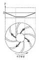
도 4a 내지 도 4c는 일정한 형태를 가진 동체의 회전에 따른 공기압 분포도를 나타낸 도면.4a to 4c are diagrams showing the air pressure distribution according to the rotation of the fuselage having a certain shape.
도 5는 본 발명에 의한 연마패드를 A방향 또는 B방향으로 회전하는 것을 나타낸 도면.5 is a view showing the rotation of the polishing pad in the A direction or B direction according to the present invention.
도 6은 연마패드를 A방향 또는 B방향으로 회전하였을 경우에서의 V/P에 대한 마찰계수(COF)를 나타낸 그래프.6 is a graph showing the coefficient of friction (COF) against V / P when the polishing pad is rotated in the A direction or B direction.
도 7은 실험조건 V와 P에 따른 V/P 연산치를 나타낸 도표.7 is a table showing V / P calculation values according to experimental conditions V and P.
*도면의 주요 부분에 대한 부호설명* Explanation of symbols on the main parts of the drawings
10 : 웨이퍼 20 : 연마패드10: wafer 20: polishing pad
21 : 연마테이블 30 : 폴리싱 헤드21: polishing table 30: polishing head
31 : 리테이너링 32 : 멤브레인31
33 : 캐리어 34 : 매니폴드33
40 : 연마 컨디셔너 50 : 슬러리 공급부40: polishing conditioner 50: slurry supply unit
102 : 연마패드 200 : 그루브102: polishing pad 200: groove
본 발명은 화학적 기계적 연마장치에 관한 것으로, 특히 연마패드와 웨이퍼의 직접적인 마찰에 의한 스크래치가 발생하지 않도록 하고자 하는 화학적 기계적 연마장치에 관한 것이다.BACKGROUND OF THE
현재 손톱만한 반도체칩 크기에 109개 이상의 소자가 집적되어 있으며 소자의 속도는 기하 급수적으로 증가하고 있다. 이렇게 소자를 고집적화, 고속화를 시키기 위해서 반도체칩의 구조적 측면과 재료적 측면에서 많은 연구가 계속되고 있다. 구조적 측면에서는 메탈층이 증가하고 있으며 또한 소자와 소자 사이를 분리하기 위하여 STI(SHALLOW TRENCH ISOLATION) 방법이 사용되고 있으며 재료적 측면에서는 구리(Cu)와 저유전율 물질(Low-k) 등이 사용되어지고 있다.Currently, more than 109 devices are integrated in the size of a semiconductor chip, and the speed of devices is increasing exponentially. In order to achieve high integration and high speed, many studies have been conducted in terms of structural and material aspects of semiconductor chips. In terms of structure, the metal layer is increasing, and the STI (SHALLOW TRENCH ISOLATION) method is used to separate the device from the device. In terms of materials, copper (Cu) and low dielectric constant (Low-k) are used. have.
특히, 화학기계적연마(CMP, chemical mechanical polishing) 공정은 메탈층이 증가함에 따라 그 쓰임새가 점점 더 중요해지고 있다. 일반적으로, 반도체 소자는 웨이퍼 상에 사진, 식각, 확산, 금속증착 등의 공정을 선택적이고도 반복적으로 수행함으로써 완성되는데, 이와같이 반도체 소자로 완성되기까지의 웨이퍼는 그 표면에 소정의 회로패턴을 형성하기 용이하도록 평탄화와 에치백(etch back) 등을 위 한 CMP 공정을 수회 수행하고 있다.In particular, the chemical mechanical polishing (CMP) process has become increasingly important as the metal layer increases. In general, a semiconductor device is completed by selectively and repeatedly performing a process such as photographing, etching, diffusion, metal deposition, etc. on a wafer. Thus, a wafer until completion of the semiconductor device forms a predetermined circuit pattern on its surface. To facilitate the planarization, the CMP process for planarization and etch back has been performed several times.
이러한 CMP 공정은 웨이퍼 표면을 연마 패드의 표면 위로 접촉하도록 한 상태에서 연마재가 분산된 슬러리를 공급하여 웨이퍼 표면을 화학적으로 반응시키면서 연마 테이블과 웨이퍼를 잡고 있는 캐리어를 상대 운동시켜 물리적으로 원하는 막을 연마하는 기술로 단차를 갖는 반도체 소자의 전면 평탄화를 구현하는 공정에서 사용된다.This CMP process supplies a slurry in which abrasive is dispersed while bringing the wafer surface into contact with the surface of the polishing pad, and chemically reacts the wafer surface to relatively move the polishing table and the carrier holding the wafer to physically polish the desired film. It is used in the process of implementing the planarization of the front surface of the semiconductor device having a step with the technology.
이하, 첨부된 도면을 참조하여 종래 기술에 의한 화학적 기계적 연마 장치를 상세히 설명하면 다음과 같다.Hereinafter, a chemical mechanical polishing apparatus according to the prior art will be described in detail with reference to the accompanying drawings.
도 1은 일반적인 화학적 기계적 연마장치의 구성도이다.1 is a block diagram of a general chemical mechanical polishing apparatus.
일반적인 화학적 기계적 연마장치는, 도 1에 도시된 바와 같이, 연마패드(20)가 상면에 부착된 연마테이블(21)과, 절연막 또는 메탈층이 형성된 웨이퍼(10)가 장착되는 폴리싱헤드(30)와, 연마패드(20) 표면에 슬러리를 투입하기 위한 슬러리 공급부(50)와, 연마공정 중에 웨이퍼가 회전하는 영역과 다른 영역에서 연마패드(20)를 연삭하기 위한 패드 컨디셔너(40)로 구성된다.As shown in FIG. 1, a general chemical mechanical polishing apparatus includes a polishing table 21 having a
즉, 웨이퍼(10)와 상기 연마테이블(21)을 밀착시킨 후 상기 웨이퍼(10)를 회전시킴과 동시에 상기 연마테이블을 회전시켜 웨이퍼와 연마패드 사이에 기계적인 연마가 이루어지도록 하고, 상기 슬러리 공급부(50)를 통하여 상기 웨이퍼(10)와 연마패드(20) 사이로 슬러리를 투입하여 웨이퍼 표면의 절연막 또는 메탈층과 반응하도록 함으로써 화학적인 연마가 이루어지도록 한다.That is, after the
이때, 화학적 기계적 연마공정에 의한 평탄화가 정밀하게 이루어지기 위해서 는 웨이퍼에 접촉하는 연마패드(20)의 표면 거칠기와 전체적 탄력이 적절하게 유지되어야 하는데, 이를 위해 상기와 같은 패드 컨디셔너를 통해 연마패드(20)의 상태를 유지시킨다.At this time, in order to precisely planarization by the chemical mechanical polishing process, the surface roughness and overall elasticity of the
구체적으로, 상기 폴리싱 헤드(30)는 매니폴드(manifold)(34), 캐리어(carrier)(33), 리테이너링(retainer ring)(31), 다공플레이트(도시하지 않음)로 이루어지는데, 상기 매니폴드(34)는 내부의 공기홀을 통해 외부로부터 공급되는 공기를 폴리싱헤드의 내부로 분산시키고, 상기 캐리어(33)는 폴리싱 헤드의 몸체에 해당하는 부분으로 다른 부분과 연결되는 중심역할을 하고, 상기 리테이너링(31)은 화학적 기계적 연마공정 중에 웨이퍼가 외부로 이탈하는 것을 방지하며, 상기 다공플레이트는 다수개의 홀이 형성되어 상기 매니폴드의 공기홀을 통해 공급된 공기가 멤브레인(32)에 압력을 가할 수 있도록 하는 역할을 한다. 상기 멤브레인(32)은 상기 다공플레이트 내부에서 웨이퍼(10)가 고정되는 부분을 감싸고 있는 탄성체로, 상기 다공플레이트의 홀을 통해 공기가 들어오면 상기 웨이퍼(10)에 압력을 가해서 화학적 기계적 연마공정 중에 상기 웨이퍼(10)가 연마패드(20)와 균일한 압력으로 접촉하도록 한다.Specifically, the
이러한 화학적 기계적 연마장치는, 상면에 연마패드(20)가 부착된 연마테이블(21)이 고속회전하는 과정에서 슬러리 공급부(50)로부터 중심부위에 공급되는 슬러리가 연마패드 표면에 균일하게 분포되고, 이러한 상태에서 웨이퍼(10)는 폴리싱헤드에 의해 테이블 일측으로부터 다른 일측으로 수평이동(Osillation)함과 동시에 고속회전함으로써 슬러리에 의한 화학적 작용과 고속 회전에 의한 기계적 작용으로 웨이퍼(10) 표면을 평탄화시키게 된다. 이때, 웨이퍼(10)와 반응한 슬러리는 연마패드(20)의 외부로 배출된다.In the chemical mechanical polishing apparatus, the slurry supplied from the
한편, 연마패드(20)와 웨이퍼(10) 사이의 기계적 마찰에 의해 연마패드(20) 표면의 평탄도가 변화하게 되는데, 소정 시간 주기를 정하여 연마 컨디셔너(40)로 연마패드(20)의 표면을 연삭하는 컨디셔닝 과정을 수행하게 된다.On the other hand, the flatness of the surface of the
이러한 컨디셔닝 과정은 웨이퍼의 연마과정에서와 마찬가지로 연마테이블(21)에 의해 연마패드(20)가 고속회전하고, 연마테이블(21)의 다른 일측으로부터 다이아몬드 등의 연삭수단이 구비된 연마 컨디셔너(40)를 연마패드(20) 표면에 근접되게 대향위치시켜 수평이동 및 고속회전시키는 과정에 의해 이루어진다.In this conditioning process, as in the polishing process of the wafer, the
이때, 상기 연마패드(20)는 폴리우레탄으로 이루어진 고분자 패드로서, 화학액과 연마제로 이루어지는 슬러리를 게재시키고, 웨이퍼(10)를 상대운동시켜 웨이퍼 표면을 가공한다.At this time, the
따라서, 슬러리 및 연마패드의 특성이 CMP 공정에 큰 영향을 끼친다. 이중 CMP 연마패드는 웨이퍼와 직접적으로 접촉하는 것으로 연마패드 표면 상태에 따라 연마율, 균일성(uniformity), 결함(defect) 등에 많은 영향을 준다.Therefore, the characteristics of the slurry and the polishing pad have a great influence on the CMP process. The dual CMP polishing pad is in direct contact with the wafer and has a great influence on polishing rate, uniformity, defect, and the like depending on the polishing pad surface condition.
한편, CMP 공정은 오버필된 절연층 또는 메탈층의 표면을 평탄화하기 위해 수행되는데, 일예로 하부배선층과 상부배선층을 연결하기 위한 플러그를 형성하는 공정에 있어서, 하부배선층이 외부로 노출되는 콘택홀 내부에 메탈층을 갭필(gap-fill)한 후 오버필(over-fill)된 메탈층을 제거하여 웨이퍼 표면을 평탄화하기 위해 수행한다.On the other hand, the CMP process is performed to planarize the surface of the overfilled insulating layer or the metal layer, for example, in the process of forming a plug for connecting the lower wiring layer and the upper wiring layer, the contact hole that the lower wiring layer is exposed to the outside After the metal layer is gap-filled, the over-filled metal layer is removed to planarize the wafer surface.
그러나, 상기와 같은 종래의 화학적 기계적 연마장치는 다음과 같은 문제점이 있다.However, the conventional chemical mechanical polishing apparatus as described above has the following problems.
즉, CMP공정은 표면평탄화라는 장점을 가지고 있는 반면, 연마패드와 웨이퍼를 접촉시켜 수평이동 및 고속 회전으로 기계적인 연마를 수행하므로 웨이퍼 표면에 스크래치를 발생시킨다는 결함을 가지고 있다.In other words, the CMP process has the advantage of surface leveling, but has a defect of causing scratches on the wafer surface because mechanical polishing is performed by contacting the polishing pad and the wafer to perform horizontal polishing and high-speed rotation.
특히, 최근의 반도체 집적회로에 있어서, 반도체 집적회로의 미세화와 관련하여 배선에 기인하는 RC 딜레이가 트랜지스터 소자에 의한 RC 딜레이에 비해 상대적으로 커지고, 또한 배선폭의 미세화와 관련하여 배선저항이 증대함에 따라서, 전도성이 뛰어나고 저항이 낮아 반도체 집적회로의 배선으로 적합한 구리계 배선으로 대체하고 있는 추세인데, 이러한 구리 재료는 기존에 연마해 왔던 알루미늄에 비해 소프트하여 CMP 공정에 의한 연마시 많은 스크래치를 유발한다는 문제점이 있었다.In particular, in recent semiconductor integrated circuits, the RC delay due to wiring in relation to the miniaturization of semiconductor integrated circuits is relatively larger than the RC delay caused by transistor elements, and the wiring resistance is increased in connection with the miniaturization of wiring width. Therefore, it has been replaced by copper-based wiring suitable for wiring of semiconductor integrated circuits because of its excellent conductivity and low resistance. This copper material is softer than aluminum which has been polished in the past, causing a lot of scratches during polishing by CMP process. There was a problem.
따라서, 본 발명은 상기 문제점을 해결하기 위해 안출한 것으로, 기존 CMP 패드와는 다르게 패드 표면에서 동압을 발생시켜 연마패드와 웨이퍼가 직접적인 마찰이 아닌 세미 접촉 또는 플로팅된 상태가 되게하여 연마패드와 웨이퍼의 직접적인 마찰에 의한 스크래치가 발생하지 않도록 하는 화학적 기계적 연마장치를 제공하는데 그 목적이 있다.Accordingly, the present invention has been made to solve the above problems, and unlike the conventional CMP pad, the dynamic pressure is generated on the pad surface so that the polishing pad and the wafer are in a semi-contacted or floated state rather than a direct friction, and thus the polishing pad and the wafer. It is an object of the present invention to provide a chemical mechanical polishing apparatus which prevents scratches from being caused by direct friction.
상기와 같은 목적을 달성하기 위한 본 발명의 화학적 기계적 연마장치는 일정한 구조의 그루브(groove)가 규칙적으로 배열되어 회전시 상승하는 동압이 발생하는 연마패드와, 상기 연마패드가 부착되는 연마테이블과, 상기 연마패드로부터 일정간격으로 이격되는 웨이퍼와, 상기 웨이퍼가 장착되고 상기 웨이퍼를 구동시키는 폴리싱 헤드와, 상기 연마패드 표면에 슬러리를 투입하기 위한 슬러리 공급부로 구성되는 것을 특징으로 한다.The chemical mechanical polishing apparatus of the present invention for achieving the above object is a polishing pad in which grooves of a predetermined structure is regularly arranged to generate a dynamic pressure rising during rotation, a polishing table to which the polishing pad is attached; A wafer spaced apart from the polishing pad at a predetermined interval, a polishing head on which the wafer is mounted and driving the wafer, and a slurry supply unit for injecting slurry onto the surface of the polishing pad.
보다 구체적으로, 헤링본(herringbone) 구조의 그루브(groove)가 규칙적으로 배열되어 회전시 상기 그루브가 꺽어지는 부분에서 상승하는 동압이 발생하는 연마패드와, 상기 연마패드가 부착되는 연마테이블과, 상기 연마패드로부터 일정간격으로 이격되어 상기 연마패드 회전시 상기 동압에 의해 일정갭이 형성되는 웨이퍼와, 상기 웨이퍼가 장착되고 상기 웨이퍼를 구동시키는 폴리싱 헤드와, 상기 연마패드 표면에 슬러리를 투입하기 위한 슬러리 공급부로 구성되는 것을 특징으로 한다.More specifically, a polishing pad in which a groove having a herringbone structure is regularly arranged to generate dynamic pressure rising at a portion where the groove is bent during rotation, a polishing table to which the polishing pad is attached, and the polishing A wafer spaced at a predetermined distance from the pad to form a predetermined gap due to the dynamic pressure when the polishing pad is rotated, a polishing head on which the wafer is mounted and driving the wafer, and a slurry supply unit for injecting slurry onto the surface of the polishing pad Characterized in that consists of.
이때, 상기 연마패드가 상기 그루브가 꺽어지는 방향과 반대방향으로 회전하는 경우에 상승하는 동압이 발생하며, 상기 동압에 의해 웨이퍼와 연마패드 사이의 직접적인 마찰이 방지된다.At this time, when the polishing pad rotates in the direction opposite to the direction in which the groove is bent, rising dynamic pressure is generated, and the dynamic pressure prevents direct friction between the wafer and the polishing pad.
상기 연마패드 회전시, 상기 웨이퍼도 폴리싱헤드에 의해 구동되는바, 연마테이블 일측에서 다른 일측으로 수평이동함과 동시에 회전하여 연마공정을 수행한다. 다만, 상기 웨이퍼의 회전방향은 상기 연마패드의 회전방향과 반대방향이 되게 하여 연마가 보다 효율적으로 이루어지게 한다.When the polishing pad is rotated, the wafer is also driven by the polishing head, so that the wafer is horizontally moved from one side to the other side of the polishing table and simultaneously rotated to perform the polishing process. However, the rotational direction of the wafer is in a direction opposite to the rotational direction of the polishing pad to make polishing more efficient.
상기 헤링본 구조의 그루브 폭비(Groove width Ratio), Lp / L는 0.22-0.5 범위 내의 수치를 가지고, 그루브의 꺽임각, β는 22도에서 32도의 사이값을 가지고, 그루브 깊이, D는 50~410㎛의 수치를 가지며, 그루브 수직 길이, γ는 0.5~4mm 범위내의 수치를 가지도록 형성되는 것을 특징으로 한다.Groove width ratio (Groove width Ratio) of the herringbone structure, Lp / L has a value within the range of 0.22-0.5, bend angle of the groove, β has a value between 22 degrees and 32 degrees, groove depth, D is 50 ~ 410 It has a value of μm, the groove vertical length, γ is characterized in that it is formed to have a value in the range 0.5 ~ 4mm.
이하, 첨부된 도면을 참조하여 본 발명에 의한 화학적 기계적 연마장치를 보다 상세히 설명하면 다음과 같다.Hereinafter, a chemical mechanical polishing apparatus according to the present invention will be described in detail with reference to the accompanying drawings.
도 2는 본 발명에 따른 연마패드의 표면을 나타낸 평면도이고, 도 3은 본 발명에 의한 그루브 형상을 설명하기 위한 평면 및 단면을 나타낸 도면이며, 도 4a 내지 도 4c는 일정한 형태를 가진 동체의 회전에 따른 공기압 분포도를 나타낸 도면이다.Figure 2 is a plan view showing the surface of the polishing pad according to the present invention, Figure 3 is a view showing a plane and a cross-sectional view for explaining the groove shape according to the present invention, Figures 4a to 4c is the rotation of the body having a constant shape Figure is a diagram showing the air pressure distribution according to.
그리고, 도 5는 본 발명에 의한 연마패드를 A방향 또는 B방향으로 회전하는 것을 나타낸 도면이고, 도 6은 연마패드를 A방향 또는 B방향으로 회전하였을 경우에서의 V/P에 대한 마찰계수(COF)를 나타낸 그래프이며, 도 7은 실험조건 V와 P에 따른 V/P 연산치를 나타낸 도표이다.5 is a view showing the rotation of the polishing pad in the A or B direction according to the present invention, Figure 6 is a friction coefficient for V / P when the polishing pad is rotated in the A or B direction ( COF) is a graph, Figure 7 is a chart showing the V / P calculation value according to the experimental conditions V and P.
본 발명에 의한 화학적 기계적 연마장치는, 절연막 또는 메탈층이 형성된 웨이퍼가 장착되는 폴리싱헤드와, 도 2에 도시된 바와 같이, 헤링본(herringbone) 구조의 그루브(groove)(200)가 규칙적으로 배열된 연마패드(102)가 부착되어 있는 연마테이블과, 상기 연마패드 표면에 슬러리를 분사하기 위한 슬러리 공급부로 구성되며, 상기 웨이퍼가 부착된 폴리싱헤드를 하강시켜 웨이퍼와 상기 연마테이블을 어느 정도 밀착시킨 후 상기 웨이퍼가 부착된 폴리싱 헤드를 연마테이블 일측으로부터 다른 일측으로 수평이동 및 회전시킴과 동시에 상기 연마테이블을 상대적으로 회전시켜 웨이퍼와 연마패드 사이에 기계적인 연마가 이루어지도록 한다.The chemical mechanical polishing apparatus according to the present invention includes a polishing head on which an insulating film or a metal layer wafer is mounted, and a
여기서, 상기 폴리싱 헤드는 다수개의 공기홀을 포함하여 외부로부터 공급되는 공기를 폴리싱헤드의 내부로 분산시키는 매니폴드와, 폴리싱 헤드의 몸체에 해 당하는 부분으로 다른 부분과 연결되는 중심역할을 하는 캐리어와, 화학적 기계적 연마공정 중에 웨이퍼가 외부로 이탈하는 것을 방지하기 위한 리테이너링과, 다수개의 홀이 형성되어 상기 매니폴드의 공기홀을 통해 공급된 공기가 멤브레인에 압력을 가할 수 있도록 하는 다공플레이트와, 상기 다공플레이트 내부에서 웨이퍼가 고정되는 부분을 감싸고 있는 탄성체로, 상기 다공플레이트의 홀을 통해 공기가 들어오면 상기 웨이퍼에 압력을 가해서 화학적 기계적 연마공정 중에 상기 웨이퍼가 연마패드와 균일한 압력으로 접촉하도록 하는 멤브레인으로 구성된다.Here, the polishing head includes a manifold for distributing air supplied from the outside, including a plurality of air holes into the polishing head, and a carrier which serves as a center corresponding to the body of the polishing head and is connected to other parts. A retaining ring for preventing the wafer from escaping to the outside during the chemical mechanical polishing process, a plurality of holes are formed, and a porous plate for allowing air supplied through the air holes of the manifold to pressurize the membrane; An elastic body that surrounds a portion where the wafer is fixed within the porous plate. When air enters through the hole of the porous plate, pressure is applied to the wafer so that the wafer contacts the polishing pad at a uniform pressure during the chemical mechanical polishing process. It consists of a membrane.
한편, 상기 슬러리공급부를 통하여 상기 웨이퍼와 연마패드 사이로 연마제 및 화학액을 포함하는 슬러리를 투입하여 웨이퍼 표면의 절연막 또는 메탈층과 반응하도록 함으로써 화학적인 연마가 이루어지도록 한다.On the other hand, the slurry is supplied between the wafer and the polishing pad between the wafer and the polishing pad containing a slurry containing a chemical and chemical to react with the insulating film or metal layer on the surface of the wafer to perform chemical polishing.
그리고, 연마공정 중에 연마패드와 웨이퍼 사이의 기계적 마찰에 의해 연마패드 표면의 그루브가 마모되거나 그루브 사이에 이물이 끼어서 평탄도가 변화하게 되는데, 상기 웨이퍼가 회전하는 영역과 다른 영역에서 연마패드를 연삭하기 위한 패드 컨디셔너를 더 구비하여 소정 시간을 주기로 상기 패드 컨디셔너를 수평이동 및 고속회전시킨다.In addition, during the polishing process, grooves on the surface of the polishing pad are abraded or foreign matter is caught between the grooves due to mechanical friction between the polishing pad and the wafer, thereby changing the flatness of the polishing pad in an area different from the area in which the wafer rotates. A pad conditioner is further provided to horizontally move and rotate the pad conditioner at predetermined time intervals.
상기 웨이퍼는 콘택홀 내부에 메탈층을 충분히 갭-필하고, 상기 메탈층이 콘택홀 외부로 오버필되어 있는 상태로, 상기 오버필된 메탈층을 제거하여 표면을 평탄화하기 위해 상기 기계적 화학적 연마공정을 수행하는 것이다. 상기 메탈층으로 알루미늄(Al), 구리(Cu) 등을 사용할 수 있다.The wafer may be sufficiently gap-filled with a metal layer inside the contact hole, and the mechanical chemical polishing process may be performed to planarize the surface by removing the overfilled metal layer while the metal layer is overfilled outside the contact hole. To do. Aluminum (Al), copper (Cu), or the like may be used as the metal layer.
그리고, 오버필된 메탈층을 평탄화하는 이외에, 불균일하게 도포된 절연층의 표면을 평탄화하기 위해 도포된 절연층에 대해 기계적 화학적 연마공정을 수행하기도 한다. 상기 절연층으로 low-k물질 등을 사용할 수 있다.In addition to planarizing the overfilled metal layer, a mechanical and chemical polishing process may be performed on the coated insulating layer to planarize the surface of the unevenly coated insulating layer. A low-k material or the like may be used as the insulating layer.
이때, 연마테이블과 폴리싱 헤드의 상대적인 고속회전에 의해 헤링본 구조의 그루브가 형성된 연마패드와 웨이퍼 사이에 동압(hydrodynamic pressure)이 발생하여 연마패드와 웨이퍼의 접촉을 완화시키면서 화학적 연마가 이루어진다. 즉, 연마패드와 웨이퍼 사이에 발생하는 동압에 의해 연마패드와 웨이퍼가 직접 접촉하지 않게 되고 일정한 간격을 유지함으로써 기계적 연마에 의한 스크래치 불량을 방지할 수 있게 된다.At this time, hydrodynamic pressure is generated between the polishing pad and the wafer on which the groove of the herringbone structure is formed by the relatively high speed rotation of the polishing table and the polishing head, and chemical polishing is performed while alleviating the contact between the polishing pad and the wafer. That is, due to the dynamic pressure generated between the polishing pad and the wafer, the polishing pad and the wafer do not come into direct contact with each other, thereby maintaining a constant gap, thereby preventing scratch defects caused by mechanical polishing.
구체적으로, 상기 헤링본 구조의 그루브(200)를 가지는 연마패드(102)에 있어서, 상기 헤링본 구조의 그루브(200)는 도 3에 도시된 바와 같은 형상을 가지게 되는데, Lp/L은 그루브 폭비(Groove width Ratio)로서 이 값은 0.22-0.5 범위 내로 한다. β는 그루브의 꺽임각으로서 22도에서 32도 사이값을 유지한다. 또한, D는 그루브 깊이로서 50~410㎛를 유지하며, γ는 헤링본 구조의 수직길이로서 0.5~4mm 범위를 유지한다.Specifically, in the
이때, 상기 헤링본 구조의 그루브는 상기 연마패드의 회전방향과 반대로 꺽이는 구조를 가지는 것을 특징으로 한다.At this time, the groove of the herringbone structure is characterized by having a structure that is bent opposite to the rotation direction of the polishing pad.
도 3에 도시된 바와 같이, 연마패드를 그루브의 꺽이는 방향과 반대방향으로 회전시키면, 이중화살표 방향으로 공기가 흘러 그루브가 꺽이는 부분에서 공기가 상승하는 부압이 발생한다. 이 부압에 의해 연마패드와 웨이퍼가 직접적으로 접촉하지 않으면서 일정한 간격을 유지할 수 있게 된다. 이러한 일정한 간격은 연마패 드와 웨이퍼의 회전이 이루어지는 연마과정 동안 계속 이루어지는데, 이로써 연마패드와의 직접적인 접촉에 의해 발생하는 웨이퍼 표면의 스크래치 불량을 없앨 수 있다.As shown in FIG. 3, when the polishing pad is rotated in a direction opposite to the bending direction of the groove, air flows in the double arrow direction to generate a negative pressure in which the air rises at the portion where the groove is broken. This negative pressure makes it possible to maintain a constant gap without directly contacting the polishing pad and the wafer. This constant spacing continues during the polishing process, where the polishing pad and wafer rotate, thereby eliminating scratches on the wafer surface caused by direct contact with the polishing pad.
구체적으로, 도 4a에 도시된 바와 같이, 좌측으로 휘어진 나선형 그루브를 가지는 동체를 반시계방향으로 회전하는 경우, 외부의 공기가 그루브를 따라 흐른 후 가운데 부분에서 상승하는 공기압분포(P)를 가지게 되어 가운데 부분에서 상승하는 동압이 발생하게 되고 외부에서는 하강하는 동압이 발생하게 된다.Specifically, as shown in FIG. 4A, when the fuselage having a spiral groove bent to the left rotates in a counterclockwise direction, the outside air flows along the groove to have an air pressure distribution P rising from the center portion. The rising dynamic pressure is generated in the middle portion, and the falling dynamic pressure is generated outside.
그리고, 도 4b에 도시된 바와 같이, 우측으로 휘어진 나선형 그루브를 가지는 동체를 반시계방향으로 회전하는 경우, 가운데 부분의 공기가 그루브를 따라 외부로 흐른후 외부에서 상승하는 공기압 분포(P)를 가지게 됨으로써 가운데 부분은 진공 상태가 되어 하강하는 동압이 발생하고 동체 외부에서는 상승하는 동압이 발생하게 된다.And, as shown in Figure 4b, when rotating the body having a helical groove bent to the right counterclockwise, to have an air pressure distribution (P) rising from the outside after the air in the middle portion flows out along the groove As a result, the central portion is in a vacuum state, and a falling dynamic pressure is generated, and a rising dynamic pressure is generated outside the body.
한편, 도 4c에 도시된 바와 같이, 헤링본 구조의 그루브를 가지는 동체를 반시계방향으로 회전하는 경우, 외부의 공기와 가운데 부분의 공기가 그루브가 꺽이는 쪽으로 흐른후 꺽이는 부분에서 상승하는 공기압 분포(P)를 가지게 되어, 그루브가 꺽이는 부분에서 상승하는 동압이 발생하게 된다.On the other hand, as shown in Figure 4c, when rotating the body having a groove of the herringbone structure in a counterclockwise direction, the air pressure distribution (P) that rises in the portion where the outside air and the air in the middle portion flows toward the groove after bending ), A rising dynamic pressure occurs at the portion where the groove is bent.
즉, 본 발명은 헤링본 형상의 그루브를 가지는 동체의 경우, 그루브가 꺽이는 부분에서 공기가 상승하여 부압이 생기는 원리를 이용한 것으로서, 연마패드의 그루브를 헤링본 형상으로 형성하고 그루브가 꺽이는 방향과 반대방향으로 회전시켜 그루브가 꺽이는 부분에서 상승하는 동압이 생기도록 하는 것을 특징으로 한다. 이 동압에 의해 연마패드와 웨이퍼의 직접적인 접촉을 막을 수 있다.That is, in the case of a body having a herringbone-shaped groove, the present invention utilizes the principle that air rises at the portion where the groove is bent, so that negative pressure is generated. It is characterized in that the dynamic pressure to rise in the portion where the groove is bent by rotating. This dynamic pressure can prevent direct contact between the polishing pad and the wafer.
한편, 헤링본 구조의 그루브를 가진 연마패드의 동압 특성은 연마 공정에서의 마찰계수 값(COF,Coefficient Of Factor)의 변화를 이용하여 실험적으로 알 수 있다. 실시예로, 구리 CMP 공정은 저압의 고속 조건하에서 실시하는바, 하기의 조건에서 실험을 실시하여 COF(Coefficient Of Factor) 값을 측정하였다.On the other hand, the dynamic pressure characteristics of the polishing pad having a herringbone groove can be experimentally determined using a change in the coefficient of friction (COF) in the polishing process. As an example, the copper CMP process was performed under low pressure and high speed conditions, and the experiment was performed under the following conditions to determine a COF (Coefficient Of Factor) value.
도 5는 연마패드를 A방향(헤링본 구조의 그루브가 꺽이는 방향과 반대방향)으로 회전하였을 경우와 B방향(헤링본 구조의 그루브가 꺽이는 방향과 동일한 방향)으로 회전하였을 경우를 나타낸 것으로, A방향으로 회전시 그루브가 꺽이는 방향에서 상승하는 동압이 발생하게 되고, B방향으로 회전시 그루브가 꺽이는 방향에서 하강하는 동압이 발생하게 된다.FIG. 5 shows a case in which the polishing pad is rotated in the A direction (opposite to the direction in which the groove of the herringbone structure is bent) and in the B direction (the same direction as the groove in the herringbone structure is to be bent). The dynamic pressure rising in the direction in which the groove is bent during rotation is generated, and the dynamic pressure lowering in the direction in which the groove is bent when rotating in the B direction is generated.
이는 도 6에서도 알 수 있는바, 도 6은 연마패드를 A방향으로 회전하였을 경우와 B방향으로 회전하였을 경우에서의 V/P에 대한 마찰계수(COF)를 나타낸 것으로서, 회전 방향에 따라 COF 값은 변화가 확연히 구분되며 A 방향으로 회전시 마찰계수(COF) 값이 작아지는 것으로 보아 이것은 상승하는 동압에 의해 웨이퍼가 떠올라 연마패드와 웨이퍼와의 마찰이 작은 것임을 알 수 있다.This is also seen in Figure 6, Figure 6 shows the coefficient of friction (COF) for V / P when the polishing pad rotated in the A direction and B direction, COF value according to the rotation direction The change in silver is clearly distinguished, and the coefficient of friction (COF) decreases when rotating in the A direction, indicating that the wafer rises due to the rising dynamic pressure, so that the friction between the polishing pad and the wafer is small.
한편, B 방향으로 회전시 COF 값이 일정한 값 이상을 유지하고 A 방향으로 회전할 때 보다 수치가 높은 것으로 보아 상승하는 동압이 발생하지 않고 하강하는 동압이 발생하여 연마패드와 웨이퍼가 계속 접촉하여 마찰되는 상태를 유지함을 알 수 있다. 따라서, 연마패드는 그루브가 꺽이는 방향과 반대가 되는 방향으로 회전시켜 웨이퍼와 연마패드가 접촉하지 않도록 한다.On the other hand, since the COF value is maintained higher than a certain value when rotating in the B direction and is higher than that when rotating in the A direction, the rising dynamic pressure does not occur and the falling dynamic pressure is generated so that the polishing pad and the wafer keep in contact with each other. It can be seen that the state is maintained. Therefore, the polishing pad is rotated in a direction opposite to the direction in which the groove is bent so that the wafer and the polishing pad do not come into contact with each other.
여기서, 상기 마찰계수 COF 값은 V/P에 대한 실험 수치로서, V/P는 도 7에서와 같은 압력(P)과 회전속도(V)의 조건하에서 연산된 수치이다. V는 웨이퍼의 회전속도이고 P는 웨이퍼에 가해지는 압력을 말한다. 이때, COF 값이 낮은 경우에서의 웨이퍼의 회전속도(V)와 웨이퍼에 가해지는 압력(P)을 알 수 있는바, V/P값이 1이상이 되도록 웨이퍼를 가압(P)하고 웨이퍼를 회전(V)시켜 웨이퍼와 연마패드의 직접적인 마찰을 방지하면서 연마공정을 수행할 수 있다.Here, the friction coefficient COF value is an experimental value for V / P, V / P is a value calculated under the conditions of the pressure (P) and the rotational speed (V) as shown in FIG. V is the rotational speed of the wafer and P is the pressure exerted on the wafer. At this time, the rotation speed (V) of the wafer and the pressure (P) applied to the wafer when the COF value is low can be known. The wafer is pressurized (P) so that the V / P value is 1 or more, and the wafer is rotated. (V) to perform the polishing process while preventing direct friction between the wafer and the polishing pad.
즉, 도 7에서의 조건 중, V/P값이 1이상이 되도록 하는 웨이퍼의 압력(P) 조건과 웨이퍼의 회전속도(V) 조건을 선택하여 이를 CMP 연마공정에 적용함으로써 물리적인 연마보다 화학적인 연마가 주(main factor)가 되는 연마공정을 수행할 수 있다.That is, among the conditions in FIG. 7, the pressure (P) condition of the wafer and the rotational speed (V) condition of the wafer such that the V / P value is 1 or more are selected and applied to the CMP polishing process. A polishing process in which phosphorus polishing is a main factor can be performed.
특히, 최근 CMP 공정에 주로 적용되는 Cu인 경우, 화학적인 작용만으로 연마가 충분히 이루어지는바, 직접적인 접촉이 불필요하다.In particular, in the case of Cu, which is mainly applied to the recent CMP process, since the polishing is sufficiently performed only by chemical action, direct contact is not necessary.
한편, 이상에서 설명한 본 발명은 상술한 실시예 및 첨부된 도면에 한정되는 것이 아니고, 본 발명의 기술적 사상을 벗어나지 않는 범위내에서 여러 가지 치환, 변형 및 변경이 가능하다는 것이 본 발명이 속하는 기술분야에서 통상의 지식을 가진 자에게 있어 명백할 것이다.On the other hand, the present invention described above is not limited to the above-described embodiment and the accompanying drawings, it is possible that various substitutions, modifications and changes within the scope without departing from the technical spirit of the present invention. It will be apparent to those of ordinary skill in Esau.
상기와 같은 본 발명에 의한 화학적 기계적 연마장치는 다음과 같은 효과가 있다.The chemical mechanical polishing apparatus according to the present invention as described above has the following effects.
즉, 연마패드에 헤링본 구조의 그루브를 형성하여 연마패드의 회전시 연마패 드 표면에서 상승하는 동압이 발생하도록 함으로써 이러한 동압을 이용하여 웨이퍼와 연마패드의 접촉을 완화시키는 동시에 화학적 기계적 연마 공정이 수행되도록 한다.That is, by forming a groove of a herringbone structure on the polishing pad to generate a dynamic pressure rising from the surface of the polishing pad when the polishing pad is rotated, the chemical mechanical polishing process is performed at the same time to mitigate the contact between the wafer and the polishing pad by using such dynamic pressure. Be sure to
따라서, 기존에 연마패드와 웨이퍼와의 직접적인 접촉에 의한 연마공정에 의해서 웨이퍼 표면에 스크래치가 발생하였는바, 본 발명에서는 연마패드와 웨이퍼 사이의 부압에 의해 마찰에 의한 스크래치를 방지할 수 있게 된다.Therefore, since a scratch has been generated on the surface of the wafer by a polishing process by direct contact between the polishing pad and the wafer, in the present invention, it is possible to prevent scratches caused by friction due to the negative pressure between the polishing pad and the wafer.
특히, Cu CMP시 Cu 재료자체의 소프트한 특성 때문에 스크래치가 다수 발생하는바, 웨이퍼와 연마패드 사이의 직접적인 마찰을 방지하고 화학적인 연마작용만으로 연마공정을 수행함으로써 스크래치 불량없이 구리가 오버필된 웨이퍼 표면을 충분히 평탄화할 수 있게 된다.In particular, many scratches occur due to the soft characteristics of Cu material itself during Cu CMP. The wafer is overfilled without scratch defects by preventing a direct friction between the wafer and the polishing pad and performing a polishing process using only chemical polishing. The surface can be sufficiently flattened.
Claims (22)
Translated fromKoreanPriority Applications (2)
| Application Number | Priority Date | Filing Date | Title |
|---|---|---|---|
| KR1020050093467AKR100752181B1 (en) | 2005-10-05 | 2005-10-05 | Chemical mechanical polishing machine |
| US11/320,608US7229341B2 (en) | 2005-10-05 | 2005-12-30 | Method and apparatus for chemical mechanical polishing |
Applications Claiming Priority (1)
| Application Number | Priority Date | Filing Date | Title |
|---|---|---|---|
| KR1020050093467AKR100752181B1 (en) | 2005-10-05 | 2005-10-05 | Chemical mechanical polishing machine |
Publications (2)
| Publication Number | Publication Date |
|---|---|
| KR20070038293A KR20070038293A (en) | 2007-04-10 |
| KR100752181B1true KR100752181B1 (en) | 2007-08-24 |
Family
ID=37902507
Family Applications (1)
| Application Number | Title | Priority Date | Filing Date |
|---|---|---|---|
| KR1020050093467AExpired - Fee RelatedKR100752181B1 (en) | 2005-10-05 | 2005-10-05 | Chemical mechanical polishing machine |
Country Status (2)
| Country | Link |
|---|---|
| US (1) | US7229341B2 (en) |
| KR (1) | KR100752181B1 (en) |
Families Citing this family (5)
| Publication number | Priority date | Publication date | Assignee | Title |
|---|---|---|---|---|
| US9180570B2 (en) | 2008-03-14 | 2015-11-10 | Nexplanar Corporation | Grooved CMP pad |
| TWI500482B (en)* | 2011-03-24 | 2015-09-21 | Nat Univ Tsing Hua | Vacuum device by using centrifugal resources |
| TWI492818B (en)* | 2011-07-12 | 2015-07-21 | Iv Technologies Co Ltd | Polishing pad, polishing method and polishing system |
| KR102059524B1 (en) | 2013-02-19 | 2019-12-27 | 삼성전자주식회사 | Chemical mechanical polishing machine and polishing head assembly |
| CN114599482A (en)* | 2019-11-04 | 2022-06-07 | 3M创新有限公司 | Polishing article, polishing system and polishing method |
Citations (1)
| Publication number | Priority date | Publication date | Assignee | Title |
|---|---|---|---|---|
| KR20030064393A (en)* | 2000-08-31 | 2003-07-31 | 멀티-플레이너 테크놀로지즈 인코포레이티드 | Chemical mechanical polishing (cmp) head, apparatus, and method and planarized semiconductor wafer produced thereby |
Family Cites Families (4)
| Publication number | Priority date | Publication date | Assignee | Title |
|---|---|---|---|---|
| JPH11216663A (en)* | 1998-02-03 | 1999-08-10 | Sony Corp | Grinding pad, grinding apparatus and grinding method |
| US20020068516A1 (en)* | 1999-12-13 | 2002-06-06 | Applied Materials, Inc | Apparatus and method for controlled delivery of slurry to a region of a polishing device |
| KR100646702B1 (en)* | 2001-08-16 | 2006-11-17 | 에스케이씨 주식회사 | Chemical mechanical polishing pads formed with holes and / or grooves |
| KR20030015567A (en)* | 2001-08-16 | 2003-02-25 | 에스케이에버텍 주식회사 | Chemical mechanical polishing pad having wave grooves |
- 2005
- 2005-10-05KRKR1020050093467Apatent/KR100752181B1/ennot_activeExpired - Fee Related
- 2005-12-30USUS11/320,608patent/US7229341B2/ennot_activeExpired - Fee Related
Patent Citations (1)
| Publication number | Priority date | Publication date | Assignee | Title |
|---|---|---|---|---|
| KR20030064393A (en)* | 2000-08-31 | 2003-07-31 | 멀티-플레이너 테크놀로지즈 인코포레이티드 | Chemical mechanical polishing (cmp) head, apparatus, and method and planarized semiconductor wafer produced thereby |
Non-Patent Citations (1)
| Title |
|---|
| 공개특허공보 2003-0064393호(2003.07.31.자 공개) |
Also Published As
| Publication number | Publication date |
|---|---|
| US7229341B2 (en) | 2007-06-12 |
| KR20070038293A (en) | 2007-04-10 |
| US20070077866A1 (en) | 2007-04-05 |
Similar Documents
| Publication | Publication Date | Title |
|---|---|---|
| US6857941B2 (en) | Multi-phase polishing pad | |
| KR100818523B1 (en) | Polishing pad | |
| US7070480B2 (en) | Method and apparatus for polishing substrates | |
| US6908366B2 (en) | Method of using a soft subpad for chemical mechanical polishing | |
| JP2000301454A (en) | Chemical mechanical polishing process and its components | |
| JPH106212A (en) | Polishing pad, polishing device and manufacture of semiconductor device | |
| CN108247528B (en) | Method for processing grinding pad | |
| US20190143477A1 (en) | Apparatus and method for planarizing substrate | |
| US7025663B2 (en) | Chemical mechanical polishing apparatus having conditioning cleaning device | |
| US6942549B2 (en) | Two-sided chemical mechanical polishing pad for semiconductor processing | |
| US6432823B1 (en) | Off-concentric polishing system design | |
| US6471566B1 (en) | Sacrificial retaining ring CMP system and methods for implementing the same | |
| KR100752181B1 (en) | Chemical mechanical polishing machine | |
| US6147001A (en) | Method of manufacturing semiconductor integrated circuit device | |
| US6248002B1 (en) | Obtaining the better defect performance of the fuse CMP process by adding slurry polish on more soft pad after slurry polish | |
| US6422929B1 (en) | Polishing pad for a linear polisher and method for forming | |
| JPH10100063A (en) | Polishing equipment | |
| US20040043698A1 (en) | Polishing pad design | |
| US6821195B1 (en) | Carrier head having location optimized vacuum holes | |
| KR100580290B1 (en) | Chemical mechanical polishing machine | |
| JPH09155721A (en) | Polishing equipment | |
| US20070251832A1 (en) | Method and apparatus for electrochemical mechanical polishing of cu with higher liner velocity for better surface finish and higher removal rate during clearance | |
| KR100557913B1 (en) | Chemical Mechanical Grinding Device | |
| JP2007109989A (en) | CMP method | |
| KR200274610Y1 (en) | CMP with a Modified Dresser |
Legal Events
| Date | Code | Title | Description |
|---|---|---|---|
| A201 | Request for examination | ||
| PA0109 | Patent application | St.27 status event code:A-0-1-A10-A12-nap-PA0109 | |
| PA0201 | Request for examination | St.27 status event code:A-1-2-D10-D11-exm-PA0201 | |
| PN2301 | Change of applicant | St.27 status event code:A-3-3-R10-R13-asn-PN2301 St.27 status event code:A-3-3-R10-R11-asn-PN2301 | |
| PN2301 | Change of applicant | St.27 status event code:A-3-3-R10-R13-asn-PN2301 St.27 status event code:A-3-3-R10-R11-asn-PN2301 | |
| E902 | Notification of reason for refusal | ||
| PE0902 | Notice of grounds for rejection | St.27 status event code:A-1-2-D10-D21-exm-PE0902 | |
| E13-X000 | Pre-grant limitation requested | St.27 status event code:A-2-3-E10-E13-lim-X000 | |
| P11-X000 | Amendment of application requested | St.27 status event code:A-2-2-P10-P11-nap-X000 | |
| P13-X000 | Application amended | St.27 status event code:A-2-2-P10-P13-nap-X000 | |
| E90F | Notification of reason for final refusal | ||
| PE0902 | Notice of grounds for rejection | St.27 status event code:A-1-2-D10-D21-exm-PE0902 | |
| P11-X000 | Amendment of application requested | St.27 status event code:A-2-2-P10-P11-nap-X000 | |
| P13-X000 | Application amended | St.27 status event code:A-2-2-P10-P13-nap-X000 | |
| PG1501 | Laying open of application | St.27 status event code:A-1-1-Q10-Q12-nap-PG1501 | |
| E701 | Decision to grant or registration of patent right | ||
| PE0701 | Decision of registration | St.27 status event code:A-1-2-D10-D22-exm-PE0701 | |
| GRNT | Written decision to grant | ||
| PR0701 | Registration of establishment | St.27 status event code:A-2-4-F10-F11-exm-PR0701 | |
| PR1002 | Payment of registration fee | St.27 status event code:A-2-2-U10-U11-oth-PR1002 Fee payment year number:1 | |
| PG1601 | Publication of registration | St.27 status event code:A-4-4-Q10-Q13-nap-PG1601 | |
| PR1001 | Payment of annual fee | St.27 status event code:A-4-4-U10-U11-oth-PR1001 Fee payment year number:4 | |
| FPAY | Annual fee payment | Payment date:20110719 Year of fee payment:5 | |
| PR1001 | Payment of annual fee | St.27 status event code:A-4-4-U10-U11-oth-PR1001 Fee payment year number:5 | |
| LAPS | Lapse due to unpaid annual fee | ||
| PC1903 | Unpaid annual fee | St.27 status event code:A-4-4-U10-U13-oth-PC1903 Not in force date:20120821 Payment event data comment text:Termination Category : DEFAULT_OF_REGISTRATION_FEE | |
| PC1903 | Unpaid annual fee | St.27 status event code:N-4-6-H10-H13-oth-PC1903 Ip right cessation event data comment text:Termination Category : DEFAULT_OF_REGISTRATION_FEE Not in force date:20120821 |