KR100751800B1 - Drying Gas Heater and Control Method - Google Patents
Drying Gas Heater and Control MethodDownload PDFInfo
- Publication number
- KR100751800B1 KR100751800B1KR1020060071070AKR20060071070AKR100751800B1KR 100751800 B1KR100751800 B1KR 100751800B1KR 1020060071070 AKR1020060071070 AKR 1020060071070AKR 20060071070 AKR20060071070 AKR 20060071070AKR 100751800 B1KR100751800 B1KR 100751800B1
- Authority
- KR
- South Korea
- Prior art keywords
- gas
- flame
- cabinet
- guide tube
- pipe
- Prior art date
- Legal status (The legal status is an assumption and is not a legal conclusion. Google has not performed a legal analysis and makes no representation as to the accuracy of the status listed.)
- Expired - Fee Related
Links
Images


Classifications
- D—TEXTILES; PAPER
- D06—TREATMENT OF TEXTILES OR THE LIKE; LAUNDERING; FLEXIBLE MATERIALS NOT OTHERWISE PROVIDED FOR
- D06F—LAUNDERING, DRYING, IRONING, PRESSING OR FOLDING TEXTILE ARTICLES
- D06F58/00—Domestic laundry dryers
- D06F58/20—General details of domestic laundry dryers
- D06F58/26—Heating arrangements, e.g. gas heating equipment
- D06F58/263—Gas heating equipment
- F—MECHANICAL ENGINEERING; LIGHTING; HEATING; WEAPONS; BLASTING
- F26—DRYING
- F26B—DRYING SOLID MATERIALS OR OBJECTS BY REMOVING LIQUID THEREFROM
- F26B21/00—Arrangements or duct systems, e.g. in combination with pallet boxes, for supplying and controlling air or gases for drying solid materials or objects
- F—MECHANICAL ENGINEERING; LIGHTING; HEATING; WEAPONS; BLASTING
- F26—DRYING
- F26B—DRYING SOLID MATERIALS OR OBJECTS BY REMOVING LIQUID THEREFROM
- F26B23/00—Heating arrangements
- F26B23/02—Heating arrangements using combustion heating
- F—MECHANICAL ENGINEERING; LIGHTING; HEATING; WEAPONS; BLASTING
- F26—DRYING
- F26B—DRYING SOLID MATERIALS OR OBJECTS BY REMOVING LIQUID THEREFROM
- F26B3/00—Drying solid materials or objects by processes involving the application of heat
- F26B3/02—Drying solid materials or objects by processes involving the application of heat by convection, i.e. heat being conveyed from a heat source to the materials or objects to be dried by a gas or vapour, e.g. air
- Y—GENERAL TAGGING OF NEW TECHNOLOGICAL DEVELOPMENTS; GENERAL TAGGING OF CROSS-SECTIONAL TECHNOLOGIES SPANNING OVER SEVERAL SECTIONS OF THE IPC; TECHNICAL SUBJECTS COVERED BY FORMER USPC CROSS-REFERENCE ART COLLECTIONS [XRACs] AND DIGESTS
- Y02—TECHNOLOGIES OR APPLICATIONS FOR MITIGATION OR ADAPTATION AGAINST CLIMATE CHANGE
- Y02B—CLIMATE CHANGE MITIGATION TECHNOLOGIES RELATED TO BUILDINGS, e.g. HOUSING, HOUSE APPLIANCES OR RELATED END-USER APPLICATIONS
- Y02B40/00—Technologies aiming at improving the efficiency of home appliances, e.g. induction cooking or efficient technologies for refrigerators, freezers or dish washers
Landscapes
- Engineering & Computer Science (AREA)
- Mechanical Engineering (AREA)
- General Engineering & Computer Science (AREA)
- Life Sciences & Earth Sciences (AREA)
- Chemical & Material Sciences (AREA)
- Combustion & Propulsion (AREA)
- Sustainable Development (AREA)
- Textile Engineering (AREA)
- Microbiology (AREA)
- Control Of Washing Machine And Dryer (AREA)
- Detail Structures Of Washing Machines And Dryers (AREA)
Abstract
Translated fromKoreanDescription
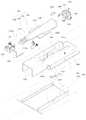
Translated fromKorean도 1은 종래 기술에 따른 건조기의 유로구조가 도시된 구성도이다.1 is a configuration diagram showing a flow path structure of a dryer according to the prior art.
도 2는 종래 기술에 따른 건조기가 도시된 부분 절개 사시도이다.Figure 2 is a partial cutaway perspective view of a dryer according to the prior art.
도 3은 본 발명의 일 실시예에 따른 가스히터를 구비하는 건조기가 도시된 구성도이다.Figure 3 is a block diagram showing a dryer having a gas heater according to an embodiment of the present invention.
도 4는 본 발명의 일 실시예에 따른 가스히터가 도시된 분해 사시도이다.4 is an exploded perspective view showing a gas heater according to an embodiment of the present invention.
도 5는 본 발명의 일 실시예에 따른 가스히터의 혼합관이 도시된 부분 확대도이다.5 is a partially enlarged view illustrating a mixing tube of a gas heater according to an embodiment of the present invention.
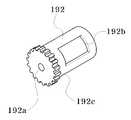
도 6은 본 발명의 일 실시예에 따른 가스히터의 흡입량조절수단이 도시된 사시도이다.6 is a perspective view showing a suction amount adjusting means of the gas heater according to an embodiment of the present invention.
도 7은 본 발명의 일 실시예에 따른 가스히터를 구비하는 건조기의 흡입유로가 도시된 평면도이다.7 is a plan view illustrating a suction channel of a dryer having a gas heater according to an embodiment of the present invention.
도 8은 본 발명의 일 실시예에 따른 가스히터를 구비하는 건조기의 순환유로가 도시된 측단면도이다.8 is a side sectional view showing a circulation passage of a dryer having a gas heater according to an embodiment of the present invention.
도 9는 본 발명의 일 실시예에 따른 가스히터를 구비하는 건조기의 배기유로 가 도시된 평면도이다.9 is a plan view illustrating an exhaust passage of a dryer having a gas heater according to an embodiment of the present invention.
도 10은 본 발명의 일 실시예에 따른 건조기용 가스히터의 제어방법이 도시된 순서도이다.10 is a flowchart illustrating a control method of a gas heater for a dryer according to an embodiment of the present invention.
<도면의 주요 부분에 관한 부호의 설명><Explanation of symbols on main parts of the drawings>
50 : 캐비닛 54 : 토출구50: cabinet 54: discharge port
60 : 드럼 62 : 지지패널60
62a : 관통홀부 64a : 배출구62a: through
70 : 흡기관 80 : 배기관70: intake pipe 80: exhaust pipe
82 : 배기팬 84 : 연결관82: exhaust fan 84: connector
86 : 하우징 90 : 구동모터86
100 : 히터 110 : 가이드관100: heater 110: guide tube
120 : 혼합관 124 : 혼합부120: mixing tube 124: mixing section
130 : 가스관 140 : 노즐130
150 : 밸브 160 : 브래킷150: valve 160: bracket
170 : 점화플러그 180 : 화염홀더170: spark plug 180: flame holder
190 : 흡입량조절수단 200 : 안착수단190: suction amount control means 200: seating means
230 : 체결수단230: fastening means
본 발명은 가스히터에 관한 것으로서, 특히 건조기에 설치되어 세탁물에 고온의 열풍을 공급하고, 불완전 연소를 억제토록 하는 건조기용 가스히터 및 그 제어방법에 관한 것이다.BACKGROUND OF THE INVENTION 1. Field of the Invention The present invention relates to a gas heater, and more particularly, to a dryer gas heater and a method of controlling the same, which are installed in a dryer to supply high temperature hot air to laundry and suppress incomplete combustion.
도 1은 종래 기술에 따른 건조기의 유로구조가 도시된 구성도이고, 도 2는 종래 기술에 따른 건조기가 도시된 부분 절개 사시도이다.1 is a configuration diagram showing a flow path structure of a dryer according to the prior art, Figure 2 is a partial cutaway perspective view showing a dryer according to the prior art.
도 1 및 도 2를 참조하면, 종래 기술에 따른 건조기는 건조기의 외관을 형성하고 전면에 피건조물 출입구가 형성된 케이스(2)와, 상기 케이스(2)의 내부에 회전 가능하게 배치되고 내부에 피건조물이 수용됨과 아울러 공기가 통과하도록 전후 방향으로 개구된 드럼(12)과, 상기 케이스(2)의 내부에 배치되어 흡입되는 공기를 가열하는 히터(18)와, 상기 히터(18)를 통과한 가열 공기를 상기 드럼(12)의 후방으로 안내하는 흡기 덕트(20)와, 피건조물을 건조시키면서 혼탁해진 공기를 상기 케이스(2)의 외부로 배출하는 배기 수단(22)과, 상기 배기 수단(22)에 설치된 송풍팬(미도시 됨)과, 상기 드럼(12)과 송풍팬을 회전 구동시키는 모터(미도시 됨) 및 벨트(40)를 포함한다.1 and 2, the dryer according to the prior art forms the appearance of the dryer and the case (2) is formed in the front door to the object, the rotatable disposed inside the case (2) and the blood inside The
상기 드럼(12)의 내주면에는 피건조물을 들어 올렸다가 낙하시키는 리프터(11)가 배치된다.A
상기 배기 수단(22)은 상기 드럼(12) 내부의 공기가 흡입되고 필터(24)가 장착되어 이물질을 거르는 린트 덕트(25)와, 상기 린트 덕트(25)와 연통되고 상기 송풍팬(30)을 에워싸는 팬 하우징(26)과, 상기 팬 하우징(26)에 일단이 연통되고 타 단이 상기 케이스(2)의 외부에 배치된 배기 덕트(27)로 구성된다.The exhaust means 22 has a
상기와 같이 구성된 종래 기술의 동작을 살펴보면 다음과 같다.Looking at the operation of the prior art configured as described above are as follows.
먼저, 상기 드럼(12)의 내부로 피건조물을 투입한 후, 도어를 닫고 건조기를 작동시키면, 모터가 구동됨에 따라 상기 드럼(12) 및 송풍팬이 회전하게 되고, 상기 히터(18)도 작동하게 된다.First, after the object is put into the
이때, 상기 드럼(12)이 회전됨에 따라 드럼(12) 내의 피건조물은 상기 리프터(11)에 의해 들어 올려졌다가 낙하된다. 그리고, 외부의 공기는 상기 송풍팬의 회전시 발생된 송풍력에 의해 상기 히터(18)의 내부로 흡입되면서 고온 저습 공기로 가열되고, 이후 상기 흡기 덕트(20)를 통해 드럼(12)의 내부로 토출된다.At this time, as the
상기 드럼(12)의 내부로 공급된 고온 저습의 공기는 낙하되는 피건조물에 직접 접촉되면서 피건조물의 건조작용을 하고 저온 고습의 공기로 변하여 상기 드럼(12)의 선단측으로 이동된 후, 상기 배기 덕트(27)를 통해 건조기의 외부로 배출된다.The air of the high temperature and low humidity supplied into the
그러나, 종래 기술에 따른 건조기는 흡기 덕트와 연통되는 관 내부에 전기 에너지의 공급에 의해 가열되는 코일이 설치되어 히터를 이루기 때문에 건조작업이 개시된 후에 히터가 가열되는데 까지 걸리는 시간을 단축하기 어려운 문제점이 있고, 비교적 고가인 전기 에너지를 열원으로 하기 때문에 건조작업에 소요되는 시간 및 비용을 절감하기 어려운 문제점이 있다.However, the dryer according to the prior art has a problem that it is difficult to shorten the time it takes for the heater to heat up after the drying operation is started because the coil is heated by the supply of electrical energy installed inside the pipe communicating with the intake duct. In addition, since relatively expensive electrical energy is used as a heat source, it is difficult to reduce the time and cost required for the drying operation.
본 발명은 상기한 종래 기술의 문제점을 개선하기 위하여 안출된 것으로서, 저가인 가스를 발열 재료로 사용하고, 가스의 불완전 연소를 억제토록 하는 건조기용 가스히터 및 그 제어방법을 제공하는데 그 목적이 있다.Disclosure of Invention The present invention has been made to solve the above-mentioned problems of the prior art, and an object thereof is to provide a gas heater for a drier and a method of controlling the same, which use inexpensive gas as a heat generating material and suppress incomplete combustion of the gas. .
상기한 과제를 해결하기 위한 본 발명에 따른 건조기용 가스히터는 캐비닛, 상기 캐비닛 일측에 설치되어 상기 캐비닛 내부에 가스를 공급하는 가스관, 상기 가스관의 내측 단부에 설치되는 노즐, 상기 가스관 일측에 설치되는 밸브, 상기 노즐 일측에 설치되어 가스와 공기가 섞이도록 하는 혼합관, 상기 혼합관 외측에 설치되어 불꽃을 일으키는 점화플러그, 상기 혼합관 외측에 설치되어 가열된 공기가 소정 공간으로 안내되도록 하는 가이드관, 및 상기 가이드관 일측에 설치되어 화염의 불완전 연소 정도를 감지하여 불완전 연소율이 설정치 이하이면 다시 발화작동을 행하는 보조점화장치를 포함하고, 상기 보조점화장치는 상기 가이드관 내벽에 설치되어 화염의 불완전 연소율을 감지하는 화염감지센서와, 상기 가이드관 내벽에 소정 간격을 유지토록 설치되는 다수 개의 보조점화플러그와, 상기 화염감지센서로부터 수신되는 신호에 따라 불완전 연소율이 설정치 이하인지를 감지하여 상기 보조점화플러그에 점화 신호를 송신하는 제어부를 포함하는 것을 특징으로 한다.Dryer gas heater according to the present invention for solving the above problems is installed in the cabinet, the gas pipe for supplying gas to the inside of the cabinet, the nozzle is installed on the inner end of the gas pipe, the gas pipe is installed on one side A valve, a mixing tube installed at one side of the nozzle to mix gas and air, an ignition plug installed outside the mixing tube to generate a flame, and a guide tube installed at the outside of the mixing tube to guide the heated air to a predetermined space. And an auxiliary ignition device installed at one side of the guide tube to detect the degree of incomplete combustion of the flame and re-ignite if the incomplete combustion rate is less than or equal to the set value. Flame detection sensor for detecting the burn rate, and maintain a predetermined interval on the inner wall of the guide tube Depending on the signals received from the plurality of secondary spark plug is lock installation, the flame sensor is characterized in that by detecting whether incomplete combustion rate is less than the set value and a control unit for transmitting a fire signal to the auxiliary ignition plug.
삭제delete
또한, 본 발명의 보조점화플러그는 상기 가이드관의 전후 방향으로 소정 간격을 유지하면서 상기 가이드관의 양측 내벽에 교호로 설치되는 제 1 보조점화플러 그와, 제 2 보조점화플러그로 이루어지는 것을 특징으로 한다.In addition, the auxiliary ignition plug of the present invention is characterized by consisting of a first auxiliary ignition plug and a second auxiliary ignition plug alternately installed on both inner walls of the guide tube while maintaining a predetermined interval in the front and rear direction of the guide tube. do.
또한, 본 발명에 따른 건조기용 가스히터의 제어방법은 캐비닛 내부의 공기와 가스관으로부터 공급되는 가스가 혼합관을 통해 가이드관에 분사되고, 점화플러그에 전원이 인가되는 연소 개시단계, 상기 연소 개시단계 후에 상기 가이드관에 설치되는 화염감지센서로부터 불완전 연소율이 감지되어 측정치가 제 1 설정치 이상인지를 판단하는 제 1 감지단계, 상기 제 1 감지단계에서 측정치가 제 1 설정치 이상이면 측정치가 제 2 설정치 이상인지를 판단하는 제 2 감지단계, 및 상기 제 1 감지단계 및 상기 제 2 감지단계에서 판단되는 정보에 의해 점화플러그, 보조점화플러그의 구동여부를 결정하는 재 점화단계를 포함하는 것을 특징으로 한다.In addition, the control method of the gas heater for a dryer according to the present invention is a combustion initiation step, the gas is supplied from the air and the gas pipe inside the cabinet is injected into the guide tube through the mixing tube, the power is applied to the spark plug, the combustion initiation step Later, a first detection step of determining whether the measured value is greater than or equal to the first set value by detecting an incomplete combustion rate from the flame detection sensor installed in the guide tube, and the measured value is greater than or equal to the second set value if the measured value is greater than or equal to the first set value in the first sensing step. And a re-ignition step of determining whether to drive the ignition plug or the auxiliary ignition plug based on information determined in the first detection step and the second detection step.
이하, 본 발명에 따른 건조기용 가스히터 및 그 제어방법의 일 실시예를 첨부된 도면들을 참조하여 상세히 설명한다.Hereinafter, an embodiment of a dryer gas heater and a control method thereof according to the present invention will be described in detail with reference to the accompanying drawings.
설명의 편의를 위해 건조기를 예로 들어 설명한다. 이 과정에서 도면에 도시된 선들의 두께나 구성요소의 크기 등은 설명의 명료성과 편의상 과장되게 도시되어 있을 수 있다.For convenience of explanation, the dryer will be described as an example. In this process, the thickness of the lines or the size of the components shown in the drawings may be exaggerated for clarity and convenience of description.
또한, 후술되는 용어들은 본 발명에서의 기능을 고려하여 정의된 용어들로서 이는 사용자, 운용자의 의도 또는 관례에 따라 달라질 수 있다.In addition, terms to be described below are terms defined in consideration of functions in the present invention, which may vary according to the intention or convention of a user or an operator.
그러므로, 이러한 용어들에 대한 정의는 본 명세서 전반에 걸친 내용을 토대로 내려져야 할 것이다.Therefore, definitions of these terms should be made based on the contents throughout the specification.
도 3은 본 발명의 일 실시예에 따른 가스히터를 구비하는 건조기가 도시된 구성도이고, 도 4는 본 발명의 일 실시예에 따른 가스히터가 도시된 분해 사시도이며, 도 5는 본 발명의 일 실시예에 따른 가스히터의 혼합관이 도시된 부분 확대도이고, 도 6은 본 발명의 일 실시예에 따른 가스히터의 흡입량조절수단이 도시된 사시도이다.3 is a block diagram showing a dryer having a gas heater according to an embodiment of the present invention, Figure 4 is an exploded perspective view showing a gas heater according to an embodiment of the present invention, Figure 5 is a view of the present invention Part is an enlarged view showing a mixing tube of a gas heater according to an embodiment, Figure 6 is a perspective view showing a suction amount adjusting means of the gas heater according to an embodiment of the present invention.
도 3 내지 도 6을 참조하면, 본 발명에 따른 건조기는 소정 공간을 이루고, 일측에 개구부가 형성되며, 흡입구(미도시) 및 토출구(54)가 형성된 캐비닛(50)과, 개구부 내측에 회전 가능하게 설치되어 세탁물이 수납되는 드럼(60)과, 드럼(60) 내벽에 설치되어 세탁물을 회전시키는 다수 개의 리프터(60a)와, 캐비닛(50) 내부의 공기가 드럼(60) 내부로 안내되도록 하는 흡기관(70)과, 흡기관(70) 일측에 설치되는 히터(100)와, 드럼(60)과 토출구(54) 사이에 설치되는 배기팬(82 : 도 9 참조)과, 배기팬(82)과 토출구(54) 사이에 설치된 배기관(80)과, 배기팬(82)의 회전축이 연결된 구동모터(90 : 도 9 참조)가 포함되어 구성된다.3 to 6, the dryer according to the present invention forms a predetermined space, an opening is formed at one side, and a
이로써, 사용자의 조작에 의해 구동모터(90)에 전원이 인가되면 배기팬(82)이 회전되면서 공기의 순환이 이루어지는데, 흡입구를 통해 유입된 공기는 히터(100)를 통과하면서 더운 공기로 변환되어 흡기관(70)을 따라 드럼(60) 내부로 공급되고, 드럼(60) 내부에서 세탁물과 접촉되면서 세탁물의 건조작동 또는 살균작동이 이루어진다.Thus, when the power is applied to the
이후에 배기팬(82)에 의해 배출되는 공기는 배기관(80)을 따라 캐비닛(50)의 토출구(54)를 통해 외부로 배출됨으로써, 공기의 순환이 이루어진다.Thereafter, the air discharged by the
여기서, 토출구(54)는 캐비닛(50)의 배면 하단의 중앙에 형성되어 드럼(60) 에서 배출되는 공기가 캐비닛(50)의 배면으로 배출되도록 한다.Here, the
그리고, 드럼(60)은 전면 및 배면이 개구된 원통 모양으로 형성되어 전면이 캐비닛(50)의 개구부에 대응되고, 관통홀부(62a)가 형성된 지지패널(62)에 배면이 회전 가능하게 설치된다.In addition, the
여기서, 지지패널(62)은 캐비닛(50)의 배면 내벽에 설치되어 드럼(60)이 회전 가능하게 지지될 수 있도록 하고, 관통홀부(62a)에 흡기관(70)이 설치된다.Here, the
또한, 드럼(60)의 전방측 단부와 캐비닛(50)의 개구부 사이에 전면패널(64)이 설치되고, 전면패널(64)의 하측 단부에 배출구(64a)가 형성된다.In addition, the
이 배출구(64a)에는 배기팬(82) 측으로 향하는 연장관(84)이 설치되고, 연장관(84)과 배기관(80) 사이에 배기팬(82)이 회전 가능하게 내장되는 하우징(86 : 도 7 참조)이 설치된다.The
또한, 흡기관(70)은 히터(100)로부터 관통홀부(62a)와 대응되는 캐비닛(50)의 배면 상부까지 연장되는 통로로 이루어짐으로써, 캐비닛(50) 내부로부터 유입되는 공기는 히터(100)를 지나면서 소정 온도 이상의 공기로 변환되어 흡기관(70)을 따라 캐비닛(50)의 상측으로 이동되고, 관통홀부(62a)를 통해 드럼(60) 내부로 유입된다.In addition, the
이때, 구동모터(90)와 벨트(미도시)로 연결된 드럼(60)이 회전되면서 더운 공기와 세탁물의 접촉면적이 증가되도록 하므로 세탁물의 건조작동 또는 살균작동이 이루어진다.At this time, as the
히터(100)는 캐비닛(50) 일측에 설치되어 캐비닛(50) 내부에 가스를 공급하 는 가스관(130)과, 가스관(130)의 내측 단부에 설치되는 노즐(140)과, 가스관(130) 일측에 설치되는 밸브(150)와, 노즐(140)에 연결되어 가스와 공기가 섞이도록 하는 혼합관(120)과, 혼합관(120) 외측에 설치되어 불꽃을 일으키는 점화플러그(170)와, 혼합관(120) 외측에 설치되어 가열된 공기가 소정 공간으로 안내되도록 하는 가이드관(110)과, 가스관(130), 혼합관(120), 가이드관(110)이 장착되며, 캐비닛(50) 내벽 일측에 설치되는 브래킷(160)과, 혼합관(120)과 가이드관(110) 사이에 설치되어 점화플러그(170)에 의해 발생되는 불꽃이 소정 크기 이상으로 크게 형성되는 것을 억제토록 하는 화염홀더(180)를 포함하여 이루어진다.The
이로써, 밸브(150)가 개방되어 가스관(130)을 따라 가스가 혼합관(120)에 공급되면 캐비닛(50) 내부의 공기와 혼합되어 혼합관(120) 외측으로 분사되고, 이때 점화플러그(170)에서 발생되는 불꽃에 의해 화염이 발생된다.Thus, when the
이렇게 발생된 화염은 화염홀더(180)에 의해 화염의 크기 및 생성 위치가 조절되어 가이드관(110) 내측에 화염이 위치되도록 함으로써, 가이드관(110)을 따라 유입되는 공기는 화염을 지나면서 고온의 열풍으로 온도가 변화되어 세탁물에 분사되므로 건조작업이 이루어진다.The flame generated in this way is controlled by the
혼합관(120)은 일측에 혼합부(124)가 형성되어 캐비닛(50) 내부의 공기가 유입되도록 하는 바, 혼합부(124)는 노즐(140)이 결합되어 가스가 혼합관(120)에 유입되도록 하고, 캐비닛(50) 내부의 공기가 소정량 유입되도록 한다.Mixing
또한, 혼합관(120)은 양측 단부에 한 쌍의 결합리브(122)가 형성되고, 결합리브(122)에는 홀부(122a)가 형성되어 후술될 브래킷(160)의 체결홀부(162a)에 볼 트에 의해 결합된다.In addition, the mixing
여기서, 혼합부(124)는 혼합관(120)의 단부가 연장되어 이루어지는 바, 중공된 원기둥 모양으로 형성되어 노즐(140)에 대응되는 단부에 노즐(140)이 억지끼움되는 삽입홀부(124a)가 형성되며, 둘레면 일측에 캐비닛(50) 내부의 공기가 흡입되는 유입홀부(124b)가 형성된다.Here, the mixing
이로써, 노즐(140)에 의해 혼합부(124) 내측에 가스가 주입될 때에 유입홀부(124b)를 통해 캐비닛(50) 내부의 공기가 혼합부(124) 내측으로 공급되므로 가스와 공기로 이루어지는 혼합가스는 혼합관(120)을 따라 유동되어 가이드관(110) 내측으로 분사된다.As a result, when gas is injected into the
혼합부(124)에 흡입량조절수단(190)이 설치되어 유입되는 공기의 양을 조절할 수 있도록 하는 바, 유입홀부(124b) 내측에 흡입량조절수단(190)이 설치되어 유입홀부(124b)의 크기를 가변시켜 유입되는 공기의 양이 조절될 수 있도록 한다.The suction amount adjusting means 190 is installed in the mixing
흡입량조절수단(190)은 혼합부(124) 내측에 회전 가능하게 설치되어 유입홀부(124b)의 크기를 가변시키는 조절관(192)과, 조절관(192) 일측에 형성되는 기어부(192c)와, 기어부(192c)에 대응되는 혼합부(124)에 형성되는 장공부(196)와, 장공부(196)를 통해 혼합부(124)에 삽입되어 기어부(192c)에 기어물림되는 종동기어(198)와, 종동기어(198)와 기어물림되는 모터(194)를 포함하여 이루어진다.Suction amount adjusting means 190 is installed in the
여기서, 조절관(192)은 일측면이 개방되고 내부가 중공된 원통 모양으로 형성되어 삽입홀부(124a)에 대응되는 정면에 흡기홀부(192a)가 형성되고, 유입홀부(124b)에 대응되는 둘레면에 조절홀부(192b)가 형성된다.Here, the
이로써, 모터(194)가 구동되면 모터(194)의 회전축에 기어물림된 종동기어(198)의 회전에 의해 조절관(192)이 회전되는 바, 조절관(192)의 조절홀부(192b)와 유입홀부(124b)가 이격되는 정도에 따라 유입홀부(124b)의 크기가 가변될 수 있다.As a result, when the
본 발명의 가스히터는 가스관(130), 혼합관(120), 가이드관(110)이 장착되며 캐비닛(50) 내벽 일측에 설치되는 브래킷(160)을 더 포함한다. 브래킷(160)에는 브래킷(160)과 캐비닛(50) 사이에 설치되어 브래킷(160)이 정확한 위치에 배치되도록 하는 안착수단(200)과, 브래킷(160)과 캐비닛(50) 사이에 설치되는 체결수단(230)이 형성된다.The gas heater of the present invention further includes a
이로써, 히터(100)의 설치시에 브래킷(160)을 안착수단(200)에 의해 캐비닛(50)의 바닥면 정확한 위치에 안착시킨 후에 체결수단(230)에 의해 브래킷(160)을 고정시킬 수 있다.Thus, the
여기서, 브래킷(160)은 그 정면 형상이 사각형에서 저면이 개방된 모양으로 전후 방향으로 긴 프레임 모양으로 형성되고, 혼합관(120)이 대응되는 상면에 형성되는 안착부(162)와, 가이드관(110)이 대응되는 후방측 단부에 단턱이 형성되어 이루어지는 지지부(168)와, 안착부(162) 일측에 형성되어 혼합관(120)이 결합되는 체결홀부(162a)를 포함하여 이루어진다.Here, the
그리고, 안착수단(200)은 브래킷(160)의 양측 단부에 형성되는 가이드 돌기(210)와, 가이드 돌기(210)에 대응되는 캐비닛(50) 내벽에 형성되어 가이드 돌기(210)가 슬라이딩되면서 끼워지는 삽입부(220)와, 가이드 돌기(210)의 외측 단부 가 절곡되어 이루어지는 스토퍼(212)를 포함하여 이루어진다.In addition, the seating means 200 is formed on the
또한, 스토퍼(212)에는 상단 일부분이 절개되어 가스관(130)이 안착되도록 하는 결합홈부(214)가 형성된다.In addition, the
이로써, 히터(100)를 설치할 때는 브래킷(160)에 혼합관(120) 및 가스관(130)을 설치한 후에 가이드 돌기(210)를 삽입부(220)에 밀어 넣고, 관통홀부(232)에 볼트를 체결하면 관통홀부(232)를 통과한 볼트가 결합홀부(234)에 체결되면서 히터(100)의 장착이 이루어진다.Thus, when installing the
화염홀더(180)는 혼합관(120)과 가이드관(110) 사이에 설치되는 바, 화염홀더(180) 일측에서 연장되어 혼합관(120) 단부에 결합되는 다수 개의 지지대(184)와, 점화플러그(170)에 대응되는 지지대(184) 일측에 형성되어 혼합관(120)과 점화플러그(170) 사이를 구획하는 커버부(188)가 포함되어 이루어진다.
또한, 화염홀더(180)는 링 모양으로 형성되는 본체(182)로부터 지지대(184)가 연장되고, 지지대(184)와 지지대(184) 사이에 다수 개의 날개(186)가 방사형으로 돌출된다.In addition, the
여기서, 날개(186)는 혼합관(120) 측으로 소정 각도를 이루며 절곡되고, 커버부(188)는 지지대(184)의 일부분이 원주 방향으로 소정량 연장되어 이루어진다.Here, the
이로써, 혼합관(120) 외측으로 분사되는 혼합가스는 점화플러그(170)에서 발생되는 불꽃에 의해 점화되는데, 커버부(188)에 의해 혼합관(120) 외측으로 분사되자마자 점화플러그(170)에 접촉되는 것이 억제되므로 화염의 발생은 혼합관(120)으로부터 소정 거리 떨어진 부위에서 나타나고, 화염홀더(180)의 본체(182)와 날 개(186)에 의해 분사되는 혼합가스가 분산되므로 발생된 화염의 모양이 가이드관(110)을 따라 길게 형성되지 않고, 화염홀더 근처에 모아지도록 형성된다.Thus, the mixed gas injected to the outside of the mixing
이러한 작용에 의해 화염은 가이드관(110) 내부 중앙부에 모여지므로 혼합관(120)이나 흡기관(70)이 화염에 의해 변형되거나 파손되는 것을 방지할 수 있게 된다.By this action, the flame is collected in the central portion inside the
도 7은 본 발명의 일 실시예에 따른 가스히터를 구비하는 건조기의 흡입유로가 도시된 평면도이고, 도 8은 본 발명의 일 실시예에 따른 가스히터를 구비하는 건조기의 순환유로가 도시된 측단면도이며, 도 9는 본 발명의 일 실시예에 따른 가스히터를 구비하는 건조기의 배기유로가 도시된 평면도이다.7 is a plan view illustrating a suction passage of a dryer having a gas heater according to an embodiment of the present invention, and FIG. 8 is a side view illustrating a circulation passage of the dryer having a gas heater according to an embodiment of the present invention. 9 is a plan view showing an exhaust passage of a dryer having a gas heater according to an embodiment of the present invention.
도 3, 도 4 및 도 7 내지 도 9를 참조하면, 본 발명에 따른 건조기용 가스히터는 가이드관(110) 일측에 설치되어 화염의 불완전 연소 정도를 감지하여 불완전 연소율이 설정치 이하이면 다시 발화작동을 행하는 보조점화장치(178)를 더 포함하여 이루어진다.3, 4 and 7 to 9, the gas heater for the dryer according to the present invention is installed on one side of the
여기서, 보조점화장치(178)는 가이드관(110) 내벽에 설치되어 화염의 불완전 연소율을 감지하는 화염감지센서(174)와, 가이드관(110) 내벽에 소정 간격을 유지토록 설치되는 다수 개의 보조점화플러그(172)와, 화염감지센서(174)로부터 수신되는 신호에 따라 불완전 연소율이 설정치 이하인지를 감지하여 보조점화플러그(172)에 점화 신호를 송신하는 제어부(미도시)를 포함하여 이루어진다.Here, the
그리고 보조점화플러그(172)는 가이드관(110)의 전후 방향으로 소정 간격을 유지하면서 가이드관(110)의 양측 내벽에 교호로 설치되는 제 1 보조점화플러 그(172a)와, 제 2 보조점화플러그(172b)로 이루어진다.The
이로써, 흡기관(70) 내부로 열풍을 공급하기 위한 연소작동이 개시되면 밸브(150)가 개방되어 가스관(130)으로부터 공급되는 가스와 캐비닛(50) 내부의 공기가 혼합관(120)에서 섞여져 점화플러그에서 생성되는 불꽃에 의해 점화되어 열에너지를 발생시킨다.Thus, when a combustion operation for supplying hot air into the
이때, 가이드관(110) 내부에서 불완전 연소가 이루어지면 화염감지센서(174)에 의해 불완전 연소가 감지되고, 제어부의 신호에 따라 보조점화플러그(172)가 구동되어 미처 연소되지 않은 물질이 연소될 수 있도록 한다.At this time, when incomplete combustion is made in the
상기와 같이 구성된 본 발명에 따른 가스히터 및 이를 구비하는 건조기의 동작을 살펴보면 다음과 같다.Looking at the operation of the gas heater and the dryer having the same according to the present invention configured as described above are as follows.
먼저, 사용자가 운전버튼(미도시)을 조작하면 구동모터(90) 및 히터(100)에 전원이 인가되어 배기팬(82) 및 드럼(60)이 회전되는 바, 배기팬(82)의 구동에 의해 흡입구를 따라 드럼(60) 내측으로 유입된 공기는 흡입구를 통과한 후에 캐비닛(50)의 배면에 수직 방향으로 길게 형성된 흡기관(70)을 따라 캐비닛(50)의 상측으로 이동되고, 이때, 히터(100)에 의해 소정 온도 이상의 고온 건조 공기로 가열된다.First, when a user operates a driving button (not shown), power is applied to the driving
이후에 관통홀부(62a)를 통해 드럼(60) 내부로 유입된 공기는 회오리 모양으로 유동되면서 세탁물과 접촉되어 건조작업을 행한다.Thereafter, the air introduced into the
드럼(60)의 개구부와 캐비닛(50) 내벽 사이에 설치된 전면패널(64)에 배출구(64a)가 형성되는 바, 건조작동을 행한 공기는 이 배출구(64a)를 따라 드럼(60) 외측으로 배출되고, 배출구(64a)에 연통되는 연결관(86)을 지나 배기팬(82)의 하우징(84)으로 유동되며, 하우징(84)에서 배기관(80)을 따라 이동되어 토출구(54)를 통해 캐비닛(50) 외측으로 배출된다.A
여기서, 히터(100)의 작동을 살펴보면, 건조작동의 개시와 함께 밸브(150)가 개방되어 노즐(140)을 통해 혼합관(120)으로 가스가 분사되고, 혼합부(124)의 유입홀부(124b)를 통해 캐비닛(50) 내부의 공기가 1차로 가스와 혼합된다.Here, looking at the operation of the
이러한 혼합가스는 혼합관(120) 외측으로 분사되는데, 혼합관(120)의 외측, 즉 가이드관(110)의 내벽에 설치된 점화플러그(170)에 의해 화염이 발생되어 흡기관(70)으로 공급되는 공기에 열에너지를 공급할 수 있게 된다.The mixed gas is injected to the outside of the mixing
아울러, 이 화염은 화염홀더(180)에 의해 가이드관(110)의 중앙부에 모아지는 형상으로 이루어져 혼합관(120) 및 흡기관(70)이 변형되거나 파손되는 것을 방지토록 하는 바, 이는 화염홀더(180)의 커버부(188)가 혼합관(120)의 토출구 측에서 혼합가스와 점화플러그(170)를 구획하므로 화염이 혼합관(120)에 가까운 쪽에 형성되지 않게 하고, 화염홀더(180)의 본체(182)와 날개(186)에 의해 혼합가스가 분산되게 하므로 화염의 형상이 가이드관(110) 내측으로 길게 형성되는 것을 억제하여 흡기관(70) 쪽에 화염이 발생되는 것을 방지할 수 있게 된다.In addition, the flame has a shape that is collected in the central portion of the
이러한 작동 중에 가이드관(110) 내부에 불완전 연소가 일어나면 캐비닛(50) 외측으로 인체에 유해한 가스가 토출되는 바, 이러한 문제점을 개선하기 위하여 보조점화장치(178)를 설치하며, 보조점화장치(178)의 제어방법은 다음과 같다.If incomplete combustion occurs inside the
도 10은 본 발명의 일 실시예에 따른 건조기용 가스히터의 제어방법이 도시 된 순서도이다.10 is a flowchart illustrating a control method of a gas heater for a dryer according to an embodiment of the present invention.
도 3, 도 7 및 도 10을 참조하면, 본 발명에 따른 건조기용 가스히터의 제어방법은 캐비닛(50) 내부의 공기와 가스관(130)으로부터 공급되는 가스가 혼합관(120)을 통해 가이드관(110)에 분사되고, 점화플러그(170)에 전원이 인가되는 연소 개시단계(S1)와, 연소 개시단계(S1) 후에 가이드관(110)에 설치되는 화염감지센서(174)로부터 불완전 연소율이 감지되어 측정치가 제 1 설정치 이상인지를 판단하는 제 1 감지단계(S2)와, 제 1 감지단계(S2)에서 측정치가 제 1 설정치 이상이면 측정치가 제 2 설정치 이상인지를 판단하는 제 2 감지단계(S3)와, 제 1 감지단계(S2) 및 제 2 감지단계(S3)에서 판단되는 정보에 의해 점화플러그(170), 보조점화플러그(172)의 구동여부를 결정하는 재 점화단계(S4)를 포함하여 이루어진다.3, 7 and 10, the control method of the gas heater for the dryer according to the present invention is a guide tube through the mixing
이로써, 가이드관(110) 내부에 설치되는 화염감지센서(174)에 의해 불완전 연소율이 측정되는 바, 이 화염감지센서(174)는 가이드관(110) 내부의 온도를 측정하는 화염으로부터 불완전 연소율을 감지할 수 있는 센서라면 어떠한 공지의 센서가 설치되어도 무방하다.As a result, the incomplete combustion rate is measured by the
이러한 화염감지센서(174)에 의해 불완전 연소율이 감지되면 감지된 측정치와 제 1 설정치를 비교하여 측정치가 제 1 설정치 보다 낮으면 점화플러그(170)만이 구동되어 정상 운전이 이루어진다.When the incomplete combustion rate is detected by the
그리고, 측정치가 제 1 설정치 보다 높고 제 2 설정치 보다 낮으면 점화플러그(170)와 제 1 보조점화플러그(172a)만이 구동되어 가이드관(110)의 중앙부에 배치되는 연소되지 않은 가스가 점화되어 연소를 이룬다.When the measured value is higher than the first set value and lower than the second set value, only the
또한, 측정치가 제 2 설정치 보다 높으면 점화플러그(170), 제 1 보조점화플러그(172a) 및 제 2 보조점화플러그(172b)가 구동되어 가이드관(110) 내부 전체에 걸쳐 발화가 이루어진다.In addition, when the measured value is higher than the second set value, the
이로써, 점화플러그(170)에 의해 발생되는 화염에 의해 미처 연소되지 않은 혼합가스가 연소되므로 가이드관(110) 내부에서의 불완전 연소를 억제토록 한다.As a result, the mixed gas which is not burned by the flame generated by the
본 발명은 도면에 도시되는 일 실시예를 참고로 하여 설명되었으나, 이는 예시적인 것에 불과하며, 당해 기술이 속하는 분야에서 통상의 지식을 가진 자라면 이로부터 다양한 변형 및 균등한 타 실시예가 가능하다는 점을 이해할 것이다.Although the present invention has been described with reference to one embodiment shown in the drawings, this is merely exemplary, and various modifications and equivalent other embodiments are possible to those skilled in the art. Will understand.
또한, 건조기를 예로 들어 설명하였으나, 이는 예시적인 것에 불과하며, 건조기에 사용되는 가스히터가 아닌 다른 제품의 가스히터에도 본 발명의 가스히터가 사용될 수 있다.In addition, although a dryer has been described as an example, this is merely exemplary, and the gas heater of the present invention may be used in a gas heater of a product other than the gas heater used in the dryer.
따라서, 본 발명의 진정한 기술적 보호범위는 아래의 특허청구범위에 의해서 정하여져야 할 것이다.Therefore, the true technical protection scope of the present invention will be defined by the claims below.
상기와 같이 구성되는 본 발명에 따른 건조기용 가스히터 및 그 제어방법은 점화플러그가 설치되는 가이드관 내측에 화염감지센서 및 보조점화플러그가 설치됨으로써, 가이드관 내부에서 불완전 연소가 일어나면 보조점화플러그로부터 불꽃이 공급되어 재 연소가 이루어질 수 있도록 하므로 불완전 연소를 억제하여 가스히터의 에너지 효율이 향상되는 이점이 있다.Dryer gas heater and control method according to the present invention configured as described above is installed by the flame sensor and the auxiliary ignition plug inside the guide tube is installed spark plug, when the incomplete combustion occurs in the guide tube from the auxiliary ignition plug Since the flame is supplied to allow recombustion, there is an advantage in that the energy efficiency of the gas heater is improved by suppressing incomplete combustion.
Claims (4)
Translated fromKoreanPriority Applications (1)
| Application Number | Priority Date | Filing Date | Title |
|---|---|---|---|
| KR1020060071070AKR100751800B1 (en) | 2006-07-27 | 2006-07-27 | Drying Gas Heater and Control Method |
Applications Claiming Priority (1)
| Application Number | Priority Date | Filing Date | Title |
|---|---|---|---|
| KR1020060071070AKR100751800B1 (en) | 2006-07-27 | 2006-07-27 | Drying Gas Heater and Control Method |
Publications (1)
| Publication Number | Publication Date |
|---|---|
| KR100751800B1true KR100751800B1 (en) | 2007-08-27 |
Family
ID=38615272
Family Applications (1)
| Application Number | Title | Priority Date | Filing Date |
|---|---|---|---|
| KR1020060071070AExpired - Fee RelatedKR100751800B1 (en) | 2006-07-27 | 2006-07-27 | Drying Gas Heater and Control Method |
Country Status (1)
| Country | Link |
|---|---|
| KR (1) | KR100751800B1 (en) |
Cited By (1)
| Publication number | Priority date | Publication date | Assignee | Title |
|---|---|---|---|---|
| CN105780430A (en)* | 2014-12-22 | 2016-07-20 | 无锡小天鹅股份有限公司 | Gas heating system for gas clothes dryer and gas clothes dryer with gas heating system |
Citations (2)
| Publication number | Priority date | Publication date | Assignee | Title |
|---|---|---|---|---|
| KR19980087742A (en)* | 1998-09-15 | 1998-12-05 | 박흥원 | High efficiency gas burner |
| KR20030021045A (en)* | 2001-09-05 | 2003-03-12 | 주식회사 엘지이아이 | Burner supporting apparatus for dryer |
- 2006
- 2006-07-27KRKR1020060071070Apatent/KR100751800B1/ennot_activeExpired - Fee Related
Patent Citations (2)
| Publication number | Priority date | Publication date | Assignee | Title |
|---|---|---|---|---|
| KR19980087742A (en)* | 1998-09-15 | 1998-12-05 | 박흥원 | High efficiency gas burner |
| KR20030021045A (en)* | 2001-09-05 | 2003-03-12 | 주식회사 엘지이아이 | Burner supporting apparatus for dryer |
Cited By (1)
| Publication number | Priority date | Publication date | Assignee | Title |
|---|---|---|---|---|
| CN105780430A (en)* | 2014-12-22 | 2016-07-20 | 无锡小天鹅股份有限公司 | Gas heating system for gas clothes dryer and gas clothes dryer with gas heating system |
Similar Documents
| Publication | Publication Date | Title |
|---|---|---|
| KR101246377B1 (en) | Gas heater and dryer therewith | |
| KR100751800B1 (en) | Drying Gas Heater and Control Method | |
| KR100762341B1 (en) | Gas heater and dryer having same | |
| KR101385098B1 (en) | Dryer having sensor for sensing laundry and control method thereof | |
| KR101246376B1 (en) | Gas heater and dryer therewith | |
| KR101385102B1 (en) | Dryer having gas heater | |
| KR20090127768A (en) | Dryer with laundry detection device and control method thereof | |
| KR100751798B1 (en) | Gas heater and dryer having same | |
| KR101211004B1 (en) | Ignition apparatus of dryer | |
| KR100795416B1 (en) | Gas heater and dryer having same | |
| KR101308512B1 (en) | Dryer having display apparatus for filter cleaning | |
| KR100526941B1 (en) | Apparatus and method for controlling cooker by using the hot airs | |
| KR100751799B1 (en) | Gas heater and dryer having same | |
| KR101308636B1 (en) | Control method of gas type dryer | |
| EP2305878B1 (en) | Control method for a gas-type clothes dryer | |
| KR101063652B1 (en) | Safety Control Device and Method of Gas Clothes Dryer | |
| KR20080057716A (en) | Gas heater and dryer having same | |
| JPH06190197A (en) | Ignition method for gas clothing drying machine | |
| KR101306037B1 (en) | Dryer having cleaning apparatus and control method thereof | |
| KR20080057707A (en) | Gas heater and dryer having same | |
| KR101211005B1 (en) | Ignition apparatus of dryer | |
| KR101431444B1 (en) | Dryer with circulation device | |
| KR101311231B1 (en) | Dryer having gas heater | |
| KR100847049B1 (en) | Gas heater and drier equipped with the same | |
| KR100476438B1 (en) | Heater control device for dryer |
Legal Events
| Date | Code | Title | Description |
|---|---|---|---|
| A201 | Request for examination | ||
| PA0109 | Patent application | St.27 status event code:A-0-1-A10-A12-nap-PA0109 | |
| PA0201 | Request for examination | St.27 status event code:A-1-2-D10-D11-exm-PA0201 | |
| D13-X000 | Search requested | St.27 status event code:A-1-2-D10-D13-srh-X000 | |
| D14-X000 | Search report completed | St.27 status event code:A-1-2-D10-D14-srh-X000 | |
| E902 | Notification of reason for refusal | ||
| PE0902 | Notice of grounds for rejection | St.27 status event code:A-1-2-D10-D21-exm-PE0902 | |
| E13-X000 | Pre-grant limitation requested | St.27 status event code:A-2-3-E10-E13-lim-X000 | |
| P11-X000 | Amendment of application requested | St.27 status event code:A-2-2-P10-P11-nap-X000 | |
| P13-X000 | Application amended | St.27 status event code:A-2-2-P10-P13-nap-X000 | |
| E701 | Decision to grant or registration of patent right | ||
| PE0701 | Decision of registration | St.27 status event code:A-1-2-D10-D22-exm-PE0701 | |
| GRNT | Written decision to grant | ||
| PR0701 | Registration of establishment | St.27 status event code:A-2-4-F10-F11-exm-PR0701 | |
| PR1002 | Payment of registration fee | St.27 status event code:A-2-2-U10-U11-oth-PR1002 Fee payment year number:1 | |
| PG1601 | Publication of registration | St.27 status event code:A-4-4-Q10-Q13-nap-PG1601 | |
| G170 | Re-publication after modification of scope of protection [patent] | ||
| PG1701 | Publication of correction | St.27 status event code:A-5-5-P10-P19-oth-PG1701 Patent document republication publication date:20080421 Republication note text:Request for Correction Notice (Document Request) Gazette number:1007518000000 Gazette reference publication date:20070827 | |
| R18-X000 | Changes to party contact information recorded | St.27 status event code:A-5-5-R10-R18-oth-X000 | |
| PR1001 | Payment of annual fee | St.27 status event code:A-4-4-U10-U11-oth-PR1001 Fee payment year number:4 | |
| PR1001 | Payment of annual fee | St.27 status event code:A-4-4-U10-U11-oth-PR1001 Fee payment year number:5 | |
| FPAY | Annual fee payment | Payment date:20120801 Year of fee payment:6 | |
| PR1001 | Payment of annual fee | St.27 status event code:A-4-4-U10-U11-oth-PR1001 Fee payment year number:6 | |
| PN2301 | Change of applicant | St.27 status event code:A-5-5-R10-R13-asn-PN2301 St.27 status event code:A-5-5-R10-R11-asn-PN2301 | |
| FPAY | Annual fee payment | Payment date:20130801 Year of fee payment:7 | |
| PR1001 | Payment of annual fee | St.27 status event code:A-4-4-U10-U11-oth-PR1001 Fee payment year number:7 | |
| R18-X000 | Changes to party contact information recorded | St.27 status event code:A-5-5-R10-R18-oth-X000 | |
| FPAY | Annual fee payment | Payment date:20140804 Year of fee payment:8 | |
| PR1001 | Payment of annual fee | St.27 status event code:A-4-4-U10-U11-oth-PR1001 Fee payment year number:8 | |
| FPAY | Annual fee payment | Payment date:20150804 Year of fee payment:9 | |
| PR1001 | Payment of annual fee | St.27 status event code:A-4-4-U10-U11-oth-PR1001 Fee payment year number:9 | |
| LAPS | Lapse due to unpaid annual fee | ||
| PC1903 | Unpaid annual fee | St.27 status event code:A-4-4-U10-U13-oth-PC1903 Not in force date:20160818 Payment event data comment text:Termination Category : DEFAULT_OF_REGISTRATION_FEE | |
| P22-X000 | Classification modified | St.27 status event code:A-4-4-P10-P22-nap-X000 | |
| PC1903 | Unpaid annual fee | St.27 status event code:N-4-6-H10-H13-oth-PC1903 Ip right cessation event data comment text:Termination Category : DEFAULT_OF_REGISTRATION_FEE Not in force date:20160818 | |
| R18-X000 | Changes to party contact information recorded | St.27 status event code:A-5-5-R10-R18-oth-X000 | |
| R18-X000 | Changes to party contact information recorded | St.27 status event code:A-5-5-R10-R18-oth-X000 | |
| PN2301 | Change of applicant | St.27 status event code:A-5-5-R10-R13-asn-PN2301 St.27 status event code:A-5-5-R10-R11-asn-PN2301 | |
| P22-X000 | Classification modified | St.27 status event code:A-4-4-P10-P22-nap-X000 | |
| PN2301 | Change of applicant | St.27 status event code:A-5-5-R10-R13-asn-PN2301 St.27 status event code:A-5-5-R10-R11-asn-PN2301 | |
| P22-X000 | Classification modified | St.27 status event code:A-4-4-P10-P22-nap-X000 |