KR100751271B1 - Plasma processing unit with a plate with a ring-shaped magnetic core between two vertical dual process chambers - Google Patents
Plasma processing unit with a plate with a ring-shaped magnetic core between two vertical dual process chambersDownload PDFInfo
- Publication number
- KR100751271B1 KR100751271B1KR1020050043227AKR20050043227AKR100751271B1KR 100751271 B1KR100751271 B1KR 100751271B1KR 1020050043227 AKR1020050043227 AKR 1020050043227AKR 20050043227 AKR20050043227 AKR 20050043227AKR 100751271 B1KR100751271 B1KR 100751271B1
- Authority
- KR
- South Korea
- Prior art keywords
- magnetic core
- process chamber
- plasma processing
- plasma
- processing apparatus
- Prior art date
- Legal status (The legal status is an assumption and is not a legal conclusion. Google has not performed a legal analysis and makes no representation as to the accuracy of the status listed.)
- Expired - Fee Related
Links
Images


Classifications
- H—ELECTRICITY
- H01—ELECTRIC ELEMENTS
- H01J—ELECTRIC DISCHARGE TUBES OR DISCHARGE LAMPS
- H01J37/00—Discharge tubes with provision for introducing objects or material to be exposed to the discharge, e.g. for the purpose of examination or processing thereof
- H01J37/32—Gas-filled discharge tubes
- H01J37/32431—Constructional details of the reactor
- H01J37/3266—Magnetic control means
- H01J37/32669—Particular magnets or magnet arrangements for controlling the discharge
- H—ELECTRICITY
- H01—ELECTRIC ELEMENTS
- H01J—ELECTRIC DISCHARGE TUBES OR DISCHARGE LAMPS
- H01J37/00—Discharge tubes with provision for introducing objects or material to be exposed to the discharge, e.g. for the purpose of examination or processing thereof
- H01J37/32—Gas-filled discharge tubes
- H01J37/32009—Arrangements for generation of plasma specially adapted for examination or treatment of objects, e.g. plasma sources
- H01J37/32082—Radio frequency generated discharge
- H01J37/321—Radio frequency generated discharge the radio frequency energy being inductively coupled to the plasma
- H—ELECTRICITY
- H01—ELECTRIC ELEMENTS
- H01J—ELECTRIC DISCHARGE TUBES OR DISCHARGE LAMPS
- H01J37/00—Discharge tubes with provision for introducing objects or material to be exposed to the discharge, e.g. for the purpose of examination or processing thereof
- H01J37/32—Gas-filled discharge tubes
- H01J37/32431—Constructional details of the reactor
- H01J37/3244—Gas supply means
- H—ELECTRICITY
- H01—ELECTRIC ELEMENTS
- H01J—ELECTRIC DISCHARGE TUBES OR DISCHARGE LAMPS
- H01J37/00—Discharge tubes with provision for introducing objects or material to be exposed to the discharge, e.g. for the purpose of examination or processing thereof
- H01J37/32—Gas-filled discharge tubes
- H01J37/32431—Constructional details of the reactor
- H01J37/32458—Vessel
- H01J37/32513—Sealing means, e.g. sealing between different parts of the vessel
- H—ELECTRICITY
- H01—ELECTRIC ELEMENTS
- H01J—ELECTRIC DISCHARGE TUBES OR DISCHARGE LAMPS
- H01J37/00—Discharge tubes with provision for introducing objects or material to be exposed to the discharge, e.g. for the purpose of examination or processing thereof
- H01J37/32—Gas-filled discharge tubes
- H01J37/32431—Constructional details of the reactor
- H01J37/32733—Means for moving the material to be treated
- H—ELECTRICITY
- H01—ELECTRIC ELEMENTS
- H01J—ELECTRIC DISCHARGE TUBES OR DISCHARGE LAMPS
- H01J37/00—Discharge tubes with provision for introducing objects or material to be exposed to the discharge, e.g. for the purpose of examination or processing thereof
- H01J37/32—Gas-filled discharge tubes
- H01J37/32431—Constructional details of the reactor
- H01J37/32798—Further details of plasma apparatus not provided for in groups H01J37/3244 - H01J37/32788; special provisions for cleaning or maintenance of the apparatus
- H01J37/32899—Multiple chambers, e.g. cluster tools
- H—ELECTRICITY
- H05—ELECTRIC TECHNIQUES NOT OTHERWISE PROVIDED FOR
- H05H—PLASMA TECHNIQUE; PRODUCTION OF ACCELERATED ELECTRICALLY-CHARGED PARTICLES OR OF NEUTRONS; PRODUCTION OR ACCELERATION OF NEUTRAL MOLECULAR OR ATOMIC BEAMS
- H05H1/00—Generating plasma; Handling plasma
- H05H1/24—Generating plasma
- H05H1/46—Generating plasma using applied electromagnetic fields, e.g. high frequency or microwave energy
- H05H1/4645—Radiofrequency discharges
- H05H1/4652—Radiofrequency discharges using inductive coupling means, e.g. coils
Landscapes
- Physics & Mathematics (AREA)
- Engineering & Computer Science (AREA)
- Plasma & Fusion (AREA)
- Chemical & Material Sciences (AREA)
- Analytical Chemistry (AREA)
- Electromagnetism (AREA)
- Spectroscopy & Molecular Physics (AREA)
- Plasma Technology (AREA)
- Drying Of Semiconductors (AREA)
- Chemical Vapour Deposition (AREA)
Abstract
Translated fromKoreanDescription
Translated fromKorean도 1은 본 발명의 제1실시예에 따른 수직형 듀얼 프로세스챔버 사이에 링형 마그네틱코어플레이트가 구비된 플라즈마처리장치의 구조 사시도이다.1 is a perspective view of a plasma processing apparatus having a ring-shaped magnetic core plate provided between a vertical dual process chamber according to a first embodiment of the present invention.
도 2a는 제1프로세스챔버의 내부 사시도이다.2A is an internal perspective view of the first process chamber.
도 2b는 제2프로세스챔버의 내부 사시도이다.2B is an internal perspective view of the second process chamber.
도 3은 링형 마그네틱코어쌍이 내장된 마그네틱코어플레이트의 분해 사시도이다.3 is an exploded perspective view of a magnetic core plate in which a ring-shaped magnetic core pair is embedded.
도 4는 마그네틱코어플레이트 내부에 가스주입구를 배치한 구조를 도시한 도면이다.4 is a diagram illustrating a structure in which a gas inlet is disposed in a magnetic core plate.
도 5는 링형 마그네틱코어쌍의 전원공급원 연결도이다.5 is a power supply connection diagram of a ring-shaped magnetic core pair.
도 6은 도 5에 따른 프로세스챔버 내부에서의 유도된 전기장을 도시한 도면이다.6 shows the induced electric field inside the process chamber according to FIG. 5.
도 7은 본 발명의 제2실시예에 따른 수직형 듀얼 프로세스챔버 사이에 링형 마그네틱코어플레이트가 구비된 플라즈마처리장치의 분해 사시도이다.7 is an exploded perspective view of a plasma processing apparatus provided with a ring-shaped magnetic core plate between vertical dual process chambers according to a second embodiment of the present invention.
도 8은 제2실시예의 두 쌍의 마그네틱코어의 전원공급원 연결도이다.Fig. 8 is a power supply connection diagram of two pairs of magnetic cores of the second embodiment.
도 9는 제3실시예에 따른 플라즈마처리장치의 마그네틱코어플레이트를 도시한 도면이다.9 is a view showing a magnetic core plate of the plasma processing apparatus according to the third embodiment.
도 10a는 여러개의 마그네틱코어가 내장된 경우의 가스주입구의 제1예를 도시한 도면이고,FIG. 10A is a view showing a first example of a gas inlet when a plurality of magnetic cores are built in FIG.
도 10b는 가스주입구와 관통홀간 연결관계를 도시한 도면이다.10B is a diagram illustrating a connection relationship between a gas inlet and a through hole.
도 11은 여러개의 마그네틱코어가 내장된 경우의 가스주입구의 다른 예를 도시한 도면으로11 is a view showing another example of the gas inlet when a plurality of magnetic cores are embedded
* 도면의 주요 부분에 대한 부호의 설명* Explanation of symbols for the main parts of the drawings
100a : 제1프로세스챔버 100b : 제2프로세스챔버100a:
101 : 가스주입구 102a, 102b : 슬릿밸브101:
103a, 103b : 배기구 104a, 105a : 서셉터103a, 103b:
104b, 105b : 피처리기판 200 : 마그네틱코어플레이트104b, 105b:
202, 301 : 진공-링 203a, 203b : 링형 마그네틱코어202, 301:
본 발명은 플라즈마처리장치에 관한 것으로, 구체적으로는 균일도가 높은 고밀도 플라즈마를 발생시킬 수 있는 플라즈마처리장치에 관한 것이다.The present invention relates to a plasma processing apparatus, and more particularly, to a plasma processing apparatus capable of generating high density plasma having high uniformity.
플라즈마는 같은 수의 음이온(positive ions)과 전자(electrons)를 포함하는 고도로 이온화된 가스이다. 현재 플라즈마 소스는 다양한 분야에서 넓게 사용되고 있다. 반도체 칩을 생산하기 위한 반도체 장치의 제조 예를 들어, 세정(cleaning), 식각(etching), 증착(deposition) 등에 사용되고 있다.Plasma is a highly ionized gas containing the same number of positive ions and electrons. Currently, plasma sources are widely used in various fields. Manufacturing of semiconductor devices for producing semiconductor chips is used, for example, in cleaning, etching, deposition, and the like.
ICP(inductive coupled plasma) 또는 TCP(transformer coupled plasma) 발생 기술에 관해서는 이 응용 분야에서 널리 연구되어 오고 있다. 전극을 이용하는 CCP(Capacitive Coupled Plasma) 방식은 플라즈마에 접촉되는 전극으로부터 불순물이 발생되어 최종 결과물에 악영향을 주게 된다. 그러나 RF ICP 방식은 플라즈마 발생을 위한 전자기 에너지를 제공함에 있어 플라즈마에 접촉되는 전극을 갖지 않는 이점을 제공한다.ICP (inductive coupled plasma) or TCP (transformer coupled plasma) generation technology has been widely studied in this application field. Capacitive Coupled Plasma (CCP) method using an electrode generates impurities from the electrode in contact with the plasma, which adversely affects the final result. However, the RF ICP scheme provides the advantage of not having an electrode in contact with the plasma in providing electromagnetic energy for plasma generation.
최근 플라즈마를 이용하는 기술 분야에서는 피처리기판이 대형화 되면서 보다 넓은 볼륨과 균일도 및 고밀도를 갖는 플라즈마소스가 요구되고 있다. 반도체 장치 분야의 경우 대형 사이즈의 웨이퍼를 효과적으로 가공할 수 있는 플라즈마 소스가 요구되고 있으며, 액정 디스플레이 패널의 생산에 있어서도 대형 사이즈의 액정 디스플레이 패널의 가공을 가능하게 하는 플라즈마 소스가 요구되고 있다.Recently, in the technical field using plasma, a plasma source having a wider volume, uniformity, and higher density is required as the substrate to be processed is enlarged. In the field of semiconductor devices, a plasma source capable of effectively processing a large size wafer is required, and a plasma source capable of processing a large size liquid crystal display panel is also required in the production of a liquid crystal display panel.
따라서 본 발명은 피처리기판의 사이즈가 증가됨에 따른 대면적 처리가 가능하고, 대면적화시 균일도와 고밀도를 달성할 수 있으며, 수율을 높일 수 있는 플라즈마 소스를 구비한 플라즈마처리장치를 제공하는데 그 목적이 있다.Accordingly, the present invention provides a plasma processing apparatus having a plasma source capable of processing a large area as the size of the substrate to be processed increases, achieving uniformity and high density when increasing the area, and increasing a yield. There is this.
상기한 기술적 과제를 달성하기 위한 본 발명의 일면은 플라즈마처리장치에 관한 것이다. 본 발명의 플라즈마처리장치는 각각 플라즈마처리가 이루어질 피처 리기판이 수직으로 놓이는 수직형 제1프로세스챔버와 제2프로세스챔버; 및 상기 제1프로세스챔버와 상기 제2프로세스챔버 사이에 수직으로 배치되며 상기 제1프로세스챔버와 상기 제2프로세스챔버 내부로 플라즈마 생성을 위한 전기장을 유도하는 권선코일이 감긴 적어도 한 쌍의 링형 마그네틱코어가 내장된 마그네틱코어플레이트를 포함한다.One aspect of the present invention for achieving the above technical problem relates to a plasma processing apparatus. The plasma processing apparatus of the present invention includes a vertical first process chamber and a second process chamber in which a feature substrate on which plasma processing is to be placed is placed vertically; And at least one pair of ring-shaped magnetic cores disposed vertically between the first process chamber and the second process chamber and wound with winding coils for inducing an electric field for generating plasma into the first process chamber and the second process chamber. It includes a built-in magnetic core plate.
바람직하게, 상기 마그네틱코어플레이트는 마그네틱코어 장착을 위한 홈을 갖는 플레이트와, 상기 플레이트의 홈에 장착되는 권선코일이 감긴 마그네틱코어쌍과, 상기 마그네틱코어쌍의 상부를 덮는 덮개를 포함한다.Preferably, the magnetic core plate includes a plate having a groove for mounting the magnetic core, a magnetic core pair wound with a winding coil mounted in the groove of the plate, and a cover covering the upper portion of the magnetic core pair.
바람직하게, 상기 플레이트의 홈은, 외측벽, 내측벽 및 바닥면을 갖는 홈 구조이고, 상기 외측벽의 일측에서는 상기 권선코일의 인출을 위한 가이드홈이 구비된다.Preferably, the groove of the plate has a groove structure having an outer wall, an inner wall and a bottom surface, and a guide groove for drawing out the winding coil is provided at one side of the outer wall.
바람직하게, 상기 내측벽은 내부를 관통하는 관통홀을 갖고, 상기 관통홀은 상기 플레이트를 관통하도록 연장되어 상기 제1프로세스챔버와 상기 제2프로세스챔버가 서로 개방되는 통로를 제공한다.Preferably, the inner wall has a through hole penetrating therein, and the through hole extends through the plate to provide a passage through which the first process chamber and the second process chamber open to each other.
바람직하게, 상기 마그네틱코어플레이트는, 상기 내측벽의 관통홀에 연결되어 가스를 공급하는 가스주입구가 구비된다.Preferably, the magnetic core plate is connected to the through hole of the inner wall is provided with a gas inlet for supplying gas.
바람직하게, 상기 가스주입구는, 상기 마그네틱코어플레이트의 수평방향의 길이만큼 연장된 메인관과, 상기 메인관으로부터 가지형태로 각각 연장되는 복수개의 서브관을 구비한다.Preferably, the gas inlet is provided with a main tube extending by the horizontal length of the magnetic core plate, and a plurality of sub tubes each extending in a branch form from the main tube.
바람직하게, 상기 가스주입구는, 상기 마그네틱코어플레이트의 수직방향의 길이만큼 연장된 메인관과, 상기 메인관으로부터 가지형태로 각각 연장되는 복수개의 서브관을 구비한다.Preferably, the gas inlet is provided with a main tube extending by the length in the vertical direction of the magnetic core plate, and a plurality of sub tubes extending in branch form from the main tube.
바람직하게, 상기 마그네틱코어가 여러 쌍 내장되고, 상기 내측벽의 관통홀이 복수개 구비되며, 상기 마그네틱코어플레이트의 최외각 부분에 배치되는 내측벽이 제공하는 관통홀들에 공통으로 가스를 공급하는 제1가스주입구와, 상기 마그네틱코어플레이트의 중앙부의 내측벽이 제공하는 관통홀들에 공통으로 가스를 공급하는 제3가스주입구와, 상기 최외각 부분과 중앙부 사이의 내측벽이 제공하는 관통홀들에 공통으로 가스를 공급하는 제2가스주입구가 구비된다.Preferably, a plurality of magnetic cores are built-in, a plurality of through-holes of the inner wall are provided, and the gas supplying common to the through-holes provided by the inner wall disposed in the outermost part of the magnetic core plate. A first gas inlet, a third gas inlet for supplying gas in common to the through holes provided by the inner wall of the center of the magnetic core plate, and through holes provided by the inner wall between the outermost part and the center part. A second gas inlet for supplying gas in common is provided.
본 발명과 본 발명의 동작상의 이점 및 본 발명의 실시예에 의하여 달성되는 목적을 충분히 이해하기 위해서는 본 발명의 바람직한 실시예를 예시하는 첨부 도면 및 첨부 도면에 기재된 내용을 참조하여야 한다. 각 도면을 이해함에 있어서, 동일한 부재는 가능한 한 동일한 참조부호로 도시하고자 함에 유의하여야 한다. 그리고 본 발명의 요지를 불필요하게 흐릴 수 있다고 판단되는 공지 기능 및 구성에 대한 상세한 기술은 생략된다.DETAILED DESCRIPTION In order to fully understand the present invention, the operational advantages of the present invention, and the objects achieved by the embodiments of the present invention, reference should be made to the accompanying drawings which illustrate preferred embodiments of the present invention and the contents described in the accompanying drawings. In understanding the drawings, it should be noted that like parts are intended to be represented by the same reference numerals as much as possible. And detailed description of known functions and configurations that are determined to unnecessarily obscure the subject matter of the present invention is omitted.
(실시예)(Example)
이하, 첨부된 도면을 참조하여 본 발명의 바람직한 실시예를 설명함으로써,본 발명의 플라즈마처리장치를 상세히 설명한다.Hereinafter, with reference to the accompanying drawings illustrating a preferred embodiment of the present invention, the plasma processing apparatus of the present invention will be described in detail.
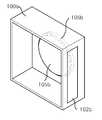
도 1은 본 발명의 제1실시예에 따른 수직형 듀얼 프로세스챔버 사이에 링형 마그네틱코어플레이트가 구비된 플라즈마처리장치의 구조 사시도이고, 도 2a는 제1프로세스챔버의 내부 사시도이며, 도 2b는 제2프로세스챔버의 내부 사시도이다.1 is a perspective view of a plasma processing apparatus having a ring-shaped magnetic core plate provided between a vertical dual process chamber according to a first embodiment of the present invention, FIG. 2A is an internal perspective view of the first process chamber, and FIG. 2 is an internal perspective view of the process chamber.
도 1, 도 2a 및 도 2b에 도시된 바와 같이, 제1실시예에 따른 플라즈마처리장치는 각각 플라즈마처리가 이루어질 피처리기판(104b, 105b)이 수직으로 놓이는 제1프로세스챔버(100a)와 제2프로세스챔버(100b)를 갖는다. 여기서, 제1프로세스챔버(100a)와 제2프로세스챔버(100b)는 수직형 듀얼 프로세스챔버를 구성한다. 그리고, 피처리기판(104b, 105b)은 수직형 제1프로세스챔버와 제2프로세스챔버의 내부에 위치하는 서셉터(104a, 105a) 위에 수직으로 놓이고, 서셉터(104a, 105a)는 제1프로세스챔버(100a)와 제2프로세스챔버(100b)에서 진공흡착방식 또는 정전방식으로 고정되어 있으며, 그리고, 제1프로세스챔버(100a)과 제2프로세스챔버(100b)의 일측에는 가스배출을 위한 배기구(103a, 103b)가 각각 구비된다. 여기서, 배기구(103a, 103b)는 서셉터(104a, 105a)의 아래에 배치된다. 그리고, 제1프로세스챔버(100a)와 제2프로세스챔버(100b)의 전면에는 피처리기판(104b, 105b)의 언로딩 및 로딩을 위한 슬릿밸브(102a, 102b)가 구비된다.1, 2A and 2B, the plasma processing apparatus according to the first embodiment includes the
그리고, 제1프로세스챔버(100a)와 제2프로세스챔버(100b) 사이에 배치되며 권선코일이 감긴 한 쌍의 링형 마그네틱코어가 내장된 마그네틱코어플레이트(200)를 갖는다. 여기서, 마그네틱코어플레이트(200)에 내장된 링형 마그네틱코어쌍은 페라이트코어(Ferrite core)이다.A
상기한 제1프로세스챔버(100a)와 마그네틱코어플레이트(200)의 일측면은 진공링(301)을 사이에 두고 밀착되며, 마그네틱코어플레이트(200)의 일측면에 밀착되는 제1프로세스챔버(100a)의 일측면은 개방된다(도 2a 참조). 그리고, 마그네틱코어플레이트(200)의 타측면과 밀착되는 제2프로세스챔버(100b)의 일측면도 개방된 다. 위와 같이, 제1프로세스챔버(100a)와 제2프로세스챔버(100b)의 개방된 측면들에 의해 마그네틱코어플레이트(200)에 내장된 링형 마그네틱코어에 의해 유도된 전기장이 제1프로세스챔버(100a)와 제2프로세스챔버(100b)의 내부에 모두에 영향을 미친다.One side of the
도 3은 링형 마그네틱코어쌍이 내장된 마그네틱코어플레이트의 분해 사시도이다.3 is an exploded perspective view of a magnetic core plate in which a ring-shaped magnetic core pair is embedded.
도 3에 도시된 바와 같이, 마그네틱코어플레이트(200)는 마그네틱코어 장착을 위한 홈을 갖는 플레이트(201), 플레이트(201)의 홈에 장착되는 권선코일이 감긴 마그네틱코어쌍(203a, 203b), 및 마그네틱코어쌍(203a, 203b)의 상부를 덮는 덮개(204)로 구성된다. 그리고, 마그네틱코어쌍(203a, 203b)과 플레이트(201)의 홈 사이에 배치되는 진공-링(202)을 더 포함한다.As shown in FIG. 3, the
도 3에서, 플레이트(201)는 플레이트본체(201a)와 플레이트본체(201a)의 내부에 구비된 홈으로 구성되는데, 플레이트본체(201a)에 구비된 홈은 마그네틱코어쌍(203a, 203b)의 모양과 동일한 홈을 형성하기 위해 외측벽(201b), 내측벽(201c) 및 바닥면을 갖는 홈 구조이고, 외측벽(201b)의 일측에서는 권선코일의 인출을 위한 가이드홈(201d)이 구비된다. 그리고, 내측벽(201c)은 내부를 관통하는 관통홀(201e)을 갖고, 관통홀(201e)은 플레이트본체(201a)까지 연장되어 제1프로세스챔버(100a)와 제2프로세스챔버(100b)가 서로 개방되는 통로를 제공한다.In FIG. 3, the
그리고, 마그네틱코어쌍(203a, 203b)은 페라이트코어의 쌍이고, 각각 권선코일이 감겨져 있다. 그리고, 덮개(204)는 마그네틱코어쌍(203a, 203b) 각각의 상부 를 덮기 위해 쌍으로 구비된다.The magnetic core pairs 203a and 203b are pairs of ferrite cores, each of which is wound with a winding coil. And, the
그리고, 진공-링(202)은 플레이트본체(201a)를 덮는 제1부분(202a)과 내측벽(201c) 상부를 덮는 제2부분(202b)으로 구성되며, 이처럼 제1부분(201a)과 제2부분(201b)으로 구성되는 진공-링(202)은 마그네틱코어쌍(203a, 203b)의 진공흡착을 더욱 강화시켜준다. 아울러, 진공-링(202)의 강한 결합을 위해 플레이트본체(201a)의 테두리는 계단구조(205)를 갖는다. 이러한 계단구조(205)는 홈의 입구에도 형성된다.The
한편, 도 1에서 가스주입구(101)는 마그네틱코어플레이트(200)의 전면에 배치되는데, 가스주입구(101)은 도 4와 같은 연결구조를 갖는다.Meanwhile, in FIG. 1, the
도 4는 마그네틱코어플레이트 내부에 가스주입구를 배치한 구조를 도시한 도면이다.4 is a diagram illustrating a structure in which a gas inlet is disposed in a magnetic core plate.
도 4에 도시된 바와 같이, 가스주입구(101)는 마그네틱코어(203a)가 장착된 홈의 내측벽(201c)에 의해 제공되는 관통홀(201e)에 연결되어 관통홀(201e)을 통해 제1프로세스챔버(100a)와 제2프로세스챔버(100b) 내부에 가스를 공급한다.As shown in FIG. 4, the
도 5는 링형 마그네틱코어쌍의 전원공급원 연결도이고, 도 6은 도 5에 따른 프로세스챔버 내부에서의 유도된 전기장을 도시한 도면이다.FIG. 5 is a power supply connection diagram of a ring-shaped magnetic core pair, and FIG. 6 is a diagram showing an induced electric field inside the process chamber according to FIG. 5.
도 5 및 도 6을 참조하면, 권선코일이 감긴 마그네틱코어쌍(203a, 203b)은 전원 공급원(RF)에 연결되고, 전원 공급원(RF)으로부터 마그네틱코어쌍(203a, 203b)으로 전원이 공급되면 마그네틱코어쌍(203a, 203b) 사이에는 권선코일에 의해 유도된 전기장(E)이 발생된다. 이러한 전기장(E)은 제1프로세스챔버(100a)와 제2프 로세스챔버(100b)에 공통으로 영향을 미치고, 이로써 플라즈마 이온 입자가 제1프로세스챔버(100a)와 제2프로세스챔버(100b) 내부에 고르게 확산된다.5 and 6, the
한편, 마그네틱코어플레이트의 각 마그네틱코어에 권선된 권선코일들은 상호 전기적으로 직렬연결되거나, 병렬연결되거나 또는 직렬과 병렬의 혼합 연결 구조로 하여 적어도 하나의 전원공급원에 연결된다.Meanwhile, the winding coils wound on the magnetic cores of the magnetic core plates are electrically connected in series, in parallel, or in a mixed connection structure in series and in parallel to at least one power source.
도 7은 본 발명의 제2실시예에 따른 수직형 듀얼 프로세스챔버 사이에 링형 마그네틱코어플레이트가 구비된 플라즈마처리장치의 분해 사시도이다.7 is an exploded perspective view of a plasma processing apparatus provided with a ring-shaped magnetic core plate between vertical dual process chambers according to a second embodiment of the present invention.
도 7에 도시된 바와 같이, 제2실시예에 따른 플라즈마처리장치는 각각 플라즈마처리가 이루어질 피처리기판이 수직으로 놓이는 제1프로세스챔버(400a)와 제2프로세스챔버(400b)를 갖는다. 여기서, 제1프로세스챔버(400a)와 제2프로세스챔버(400b)는 수직형 듀얼 프로세스챔버를 구성한다. 그리고, 도시되지 않았지만, 제1실시예와 동일하게 피처리기판은 수직형 제1프로세스챔버(400a)와 제2프로세스챔버(400b)의 내부에 위치하는 서셉터 위에 수직으로 놓이고, 서셉터는 제1프로세스챔버(400a)와 제2프로세스챔버(400b)에서 진공흡착방식 또는 정전방식으로 고정되어 있으며, 그리고, 제1프로세스챔버(400a)과 제2프로세스챔버(400b)의 일측에는 가스배출을 위한 배기구(420a, 420b)가 각각 구비된다. 여기서, 배기구(420a, 420b)는 서셉터의 아래에 배치된다. 그리고, 제1프로세스챔버(400a)와 제2프로세스챔버(400b)의 전면에는 피처리기판의 언로딩 및 로딩을 위한 슬릿밸브(410a, 410b)가 구비된다.As shown in FIG. 7, the plasma processing apparatus according to the second embodiment has a
그리고, 제1프로세스챔버(400a)와 제2프로세스챔버(400b) 사이에 배치되며 권선코일이 감긴 두 쌍의 링형 마그네틱코어(520a, 520b)(520c, 520d)가 내장된 마그네틱코어플레이트(500)를 갖는다. 여기서, 마그네틱코어플레이트(500)에 내장된 두 쌍의 링형 마그네틱코어(520a, 520b)(520c, 520d)는 페라이트코어(Ferrite core)이다.In addition, a
상기한 제1프로세스챔버(400a)와 마그네틱코어플레이트(500)의 일측면은 진공-링(600)을 사이에 두고 밀착되며, 마그네틱코어플레이트(500)의 일측면에 밀착되는 제1프로세스챔버(400a)의 일측면은 개방된다. 그리고, 마그네틱코어플레이트(500)의 타측면과 밀착되는 제2프로세스챔버(400b)의 일측면도 개방된다. 위와 같이, 제1프로세스챔버(400a)와 제2프로세스챔버(400b)의 개방된 측면들에 의해 마그네틱코어플레이트(500)에 내장된 링형 마그네틱코어에 의해 유도된 전기장이 제1프로세스챔버(400a)와 제2프로세스챔버(400b)의 내부에 모두에 영향을 미친다.One side of the
그리고, 마그네틱코어플레이트(500)는 제1실시예와 유사하게 마그네틱코어쌍(520a, 520b)(520c, 520d)의 모양과 동일한 홈을 형성하기 위해 외측벽(511), 내측벽(512) 및 바닥면을 갖는 홈 구조를 갖고, 이 홈 구조에 장착되는 권선코일이 감긴 마그네틱코어쌍(520a, 520b)(520c, 520d), 및 마그네틱코어쌍(520a, 520b)(520c, 520d)의 상부를 덮는 덮개(540a, 540b, 540c, 540d)로 구성된다. 그리고, 마그네틱코어쌍(520a, 520b)(520c, 520d)과 홈 사이에 배치되는 진공-링(530)을 더 포함한다. 여기서, 진공-링(530)은 마그네틱코어플레이트(500)의 본체를 덮는 제1부분(530a)과 내측벽(512) 상부를 덮는 제2부분(530b)으로 구성되며, 이처럼 제1부분(530a)과 제2부분(530b)으로 구성되는 진공-링(530)은 마그네틱코어쌍 (520a, 520b)(520c, 520d)의 진공흡착을 더욱 강화시켜준다. 아울러, 진공-링(530)의 강한 결합을 위해 마그네틱코어플레이트(500)의 테두리는 계단구조를 갖는다. 이러한 계단구조는 홈의 입구에도 형성된다.In addition, the
도 8은 제2실시예의 두 쌍의 마그네틱코어의 전원공급원 연결도이다.Fig. 8 is a power supply connection diagram of two pairs of magnetic cores of the second embodiment.
도 8을 참조하면, 권선코일이 감긴 두 쌍의 마그네틱코어쌍(520a, 520b)(520c, 520d)은 각각 전원 공급원(RF1, RF2)에 연결되고, 전원 공급원(RF1, RF2)으로부터 마그네틱코어쌍(520a, 520b)(520c, 520d)으로 전원이 공급되면 각 쌍의 마그네틱코어쌍(520a, 520b)(520c, 520d) 사이에는 권선코일에 의해 유도된 전기장(E1. E2)이 발생된다. 이러한 전기장(E1, E2)에 의해 플라즈마 이온 입자가 프로세스챔버의 제1프로세스챔버(400a)과 제2프로세스챔버(400b) 내부에 고르게 확산된다.Referring to FIG. 8, two pairs of
도 9는 제3실시예에 따른 플라즈마처리장치의 마그네틱코어플레이트를 도시한 도면으로서, 마그네틱코어플레이트(500)에 여러개의 링형 마그네틱코어(203)가 내장되어 있다.FIG. 9 is a view showing a magnetic core plate of the plasma processing apparatus according to the third embodiment, in which a plurality of ring-shaped
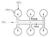
도 10a는 여러개의 마그네틱코어가 내장된 경우의 가스주입구의 제1예를 도시한 도면이고, 도 10b는 가스주입구와 관통홀간 연결관계를 도시한 도면이다.FIG. 10A is a diagram illustrating a first example of a gas inlet when a plurality of magnetic cores are embedded, and FIG. 10B is a diagram illustrating a connection relationship between a gas inlet and a through hole.
도 10a 및 도 10b에 도시된 바와 같이, 가스주입구(101)는 마그네틱코어플레이트의 수평방향의 길이만큼 연장된 메인관(101a)과, 메인관(101a)으로부터 가지(Branch) 형태로 각각 연장되는 복수개의 서브관(101b)을 구비한다.As shown in FIGS. 10A and 10B, the
여기서, 서브관(101b)은 마그네틱코어플레이트의 내측벽(201c)이 제공하는 관통홀(201e)에 연결되는 것으로, 관통홀(201e)의 갯수와 동일하다.Here, the
이러한 가스주입구(101)는 마그네틱코어플레이트의 수직 방향의 길이만큼 연장된 메인관(101a)과, 메인관(101a)으로부터 가지(Branch) 형태로 각각 연장되는 복수개의 서브관(101b)을 구비하는 구조도 적용 가능하다.The
따라서, 제1실시예와 같이 한 쌍의 마그네틱코어가 내장되는 경우에는 서브관(101b)이 2개 구비되며, 제2실시예와 같이 두 쌍의 마그네틱코어가 내장되는 경우에는 서브관(101b)이 4개 구비된다. 마그네틱코어의 갯수만큼 서브관은 구비될 것이다.Therefore, when a pair of magnetic cores are embedded as in the first embodiment, two
도 11은 여러개의 마그네틱코어가 내장된 경우의 가스주입구의 다른 예를 도시한 도면으로서, 여러개의 마그네틱코어가 내장되는 경우에 마그네틱코어플레이트의 최외각 부분에 배치되는 내측벽(201c)이 제공하는 관통홀(201e)들에 공통으로 제1가스주입구(101a)가 구비되고, 중앙부의 내측벽(201c)이 제공하는 관통홀(201e)들에 공통으로 제3가스주입구(101c)가 구비되며, 최외각 부분과 중앙부 사이의 내측벽(201c)이 제공하는 관통홀(201e)들에 공통으로 제2가스주입구(101b)가 구비된다.FIG. 11 is a view showing another example of a gas inlet when a plurality of magnetic cores are embedded, and provided by an
이처럼, 가스공급은 여러개의 관통홀(201e)들을 묶어서 한꺼번에 공급할 수 있고, 각 가스주입구의 가스공급은 밸브의 개폐를 통해 이루어진다.In this way, the gas supply can supply a plurality of through-
상술한 바와 같이, 본 발명은 도면에 도시된 실시예를 참고로 설명되었으나 이는 예시적인 것에 불과하며, 본 발명이 속한 기술분야의 통상의 지식을 가진 자라면 이로부터 다양한 변형 및 균등한 타 실시예가 가능하다는 점을 잘 알 수 있을 것이다. 그럼으로 본 발명의 진정한 기술적 보호 범위는 첨부된 특허청구범위의 기술적 사상에 의해 정해져야 할 것이다.As described above, the present invention has been described with reference to the embodiments shown in the drawings, but this is merely exemplary, and those skilled in the art to which the present invention pertains have various modifications and equivalent embodiments. You can see that it is possible. Therefore, the true technical protection scope of the present invention will be defined by the technical spirit of the appended claims.
상술한 바와 같은 본 발명의 플라즈마소스(링형 마그네틱코어)에 의하면, 수직형 듀얼 프로세스챔버에 놓인 피처리기판을 한꺼번에 플라즈마처리할수 있으므로 생산성 및 효율이 높은 플라즈마처리장치를 구현할 수 있는 효과가 있다. 또한, 본 발명은 링형 마그네틱코어의 단위 구조를 반복하여 확장함으로서 대면적화가 용이하고, 균일도와 고밀도의 플라즈마를 얻을 수 있는 효과가 있다. 또한, 본 발명은 한번에 두 챔버에 놓인 피처리기판을 처리하는 이중 처리 구조를 구현하므로서 고속 플라즈마처리가 가능한 효과가 있다.According to the plasma source (ring-type magnetic core) of the present invention as described above, since the substrate to be processed in the vertical dual process chamber can be plasma-processed at once, there is an effect of implementing a plasma processing apparatus with high productivity and efficiency. In addition, the present invention has an effect that it is easy to increase the large area and to obtain a uniform and high-density plasma by repeatedly expanding the unit structure of the ring-shaped magnetic core. In addition, the present invention has the effect of enabling a high-speed plasma treatment by implementing a dual processing structure for processing the substrate to be placed in two chambers at once.
Claims (15)
Translated fromKoreanPriority Applications (1)
| Application Number | Priority Date | Filing Date | Title |
|---|---|---|---|
| KR1020050043227AKR100751271B1 (en) | 2005-05-23 | 2005-05-23 | Plasma processing unit with a plate with a ring-shaped magnetic core between two vertical dual process chambers |
Applications Claiming Priority (1)
| Application Number | Priority Date | Filing Date | Title |
|---|---|---|---|
| KR1020050043227AKR100751271B1 (en) | 2005-05-23 | 2005-05-23 | Plasma processing unit with a plate with a ring-shaped magnetic core between two vertical dual process chambers |
Publications (2)
| Publication Number | Publication Date |
|---|---|
| KR20060120967A KR20060120967A (en) | 2006-11-28 |
| KR100751271B1true KR100751271B1 (en) | 2007-08-23 |
Family
ID=37706929
Family Applications (1)
| Application Number | Title | Priority Date | Filing Date |
|---|---|---|---|
| KR1020050043227AExpired - Fee RelatedKR100751271B1 (en) | 2005-05-23 | 2005-05-23 | Plasma processing unit with a plate with a ring-shaped magnetic core between two vertical dual process chambers |
Country Status (1)
| Country | Link |
|---|---|
| KR (1) | KR100751271B1 (en) |
Families Citing this family (1)
| Publication number | Priority date | Publication date | Assignee | Title |
|---|---|---|---|---|
| KR102528458B1 (en)* | 2015-10-30 | 2023-05-04 | (주) 엔피홀딩스 | Magnetic core assembly for transformer coupled plasma reactor |
Citations (2)
| Publication number | Priority date | Publication date | Assignee | Title |
|---|---|---|---|---|
| JPH0834208B2 (en)* | 1988-06-29 | 1996-03-29 | 株式会社日立製作所 | Plasma processing apparatus and method thereof |
| US5998933A (en)* | 1998-04-06 | 1999-12-07 | Shun'ko; Evgeny V. | RF plasma inductor with closed ferrite core |
- 2005
- 2005-05-23KRKR1020050043227Apatent/KR100751271B1/ennot_activeExpired - Fee Related
Patent Citations (2)
| Publication number | Priority date | Publication date | Assignee | Title |
|---|---|---|---|---|
| JPH0834208B2 (en)* | 1988-06-29 | 1996-03-29 | 株式会社日立製作所 | Plasma processing apparatus and method thereof |
| US5998933A (en)* | 1998-04-06 | 1999-12-07 | Shun'ko; Evgeny V. | RF plasma inductor with closed ferrite core |
Also Published As
| Publication number | Publication date |
|---|---|
| KR20060120967A (en) | 2006-11-28 |
Similar Documents
| Publication | Publication Date | Title |
|---|---|---|
| US7952048B2 (en) | Plasma source with discharge inducing bridge and plasma processing system using the same | |
| US5591268A (en) | Plasma process with radicals | |
| KR101445226B1 (en) | Exhaust ring assembly and apparatus for treating including the assembly | |
| KR100845890B1 (en) | Large Area Inductively Coupled Plasma Reactor | |
| TWI841941B (en) | Plasma generation unit, and apparatus for treating substrate with the same | |
| JP2021125675A (en) | Substrate processing equipment and substrate processing method | |
| JP2001181848A (en) | Plasma processing equipment | |
| KR100761687B1 (en) | Plasma processing unit equipped with a capacitively coupled plasma source and a vertical dual process chamber | |
| KR20220049926A (en) | Substrate Processing apparatus | |
| KR101358780B1 (en) | Plasma reactor having inductively coupled plasma source with heater | |
| KR100751271B1 (en) | Plasma processing unit with a plate with a ring-shaped magnetic core between two vertical dual process chambers | |
| KR20090073327A (en) | High Density Remote Plasma Processing Unit | |
| KR101484273B1 (en) | Plasma reactor and substrate processing system having the same | |
| KR102782921B1 (en) | Hybrid plasma generator | |
| KR100798355B1 (en) | Plasma processing apparatus having an external winding coil for processing a large area | |
| JP2021077837A (en) | Substrate processing device | |
| TWI406336B (en) | High-density plasma generator | |
| KR100772452B1 (en) | Inductively Coupled Plasma Reactor with Multiple Radio Frequency Antennas | |
| TW202341229A (en) | Substrate treating apparatus | |
| KR20040096044A (en) | Inductive plasma chamber having multi discharge tube bridge | |
| KR100761745B1 (en) | Plasma processing equipment equipped with a rod-shaped magnetic core between vertical dual process chambers | |
| KR101411994B1 (en) | Susceptor having inductively coupled plasma source and plasma process chamber | |
| KR20050049169A (en) | System for generating inductively coupled plasma and antenna coil structure for generating inductive electric field | |
| KR100845885B1 (en) | Large Area Inductively Coupled Plasma Reactor | |
| KR20070121395A (en) | Inductively Coupled Plasma Antenna |
Legal Events
| Date | Code | Title | Description |
|---|---|---|---|
| A201 | Request for examination | ||
| PA0109 | Patent application | St.27 status event code:A-0-1-A10-A12-nap-PA0109 | |
| PA0201 | Request for examination | St.27 status event code:A-1-2-D10-D11-exm-PA0201 | |
| E902 | Notification of reason for refusal | ||
| PE0902 | Notice of grounds for rejection | St.27 status event code:A-1-2-D10-D21-exm-PE0902 | |
| PG1501 | Laying open of application | St.27 status event code:A-1-1-Q10-Q12-nap-PG1501 | |
| T11-X000 | Administrative time limit extension requested | St.27 status event code:U-3-3-T10-T11-oth-X000 | |
| P11-X000 | Amendment of application requested | St.27 status event code:A-2-2-P10-P11-nap-X000 | |
| P13-X000 | Application amended | St.27 status event code:A-2-2-P10-P13-nap-X000 | |
| T11-X000 | Administrative time limit extension requested | St.27 status event code:U-3-3-T10-T11-oth-X000 | |
| E13-X000 | Pre-grant limitation requested | St.27 status event code:A-2-3-E10-E13-lim-X000 | |
| P11-X000 | Amendment of application requested | St.27 status event code:A-2-2-P10-P11-nap-X000 | |
| P13-X000 | Application amended | St.27 status event code:A-2-2-P10-P13-nap-X000 | |
| E701 | Decision to grant or registration of patent right | ||
| PE0701 | Decision of registration | St.27 status event code:A-1-2-D10-D22-exm-PE0701 | |
| GRNT | Written decision to grant | ||
| PR0701 | Registration of establishment | St.27 status event code:A-2-4-F10-F11-exm-PR0701 | |
| PR1002 | Payment of registration fee | St.27 status event code:A-2-2-U10-U11-oth-PR1002 Fee payment year number:1 | |
| PG1601 | Publication of registration | St.27 status event code:A-4-4-Q10-Q13-nap-PG1601 | |
| G170 | Re-publication after modification of scope of protection [patent] | ||
| PG1701 | Publication of correction | St.27 status event code:A-5-5-P10-P19-oth-PG1701 Patent document republication publication date:20080418 Republication note text:Request for Correction Notice (Document Request) Gazette number:1007512710000 Gazette reference publication date:20070823 | |
| PN2301 | Change of applicant | St.27 status event code:A-5-5-R10-R13-asn-PN2301 St.27 status event code:A-5-5-R10-R11-asn-PN2301 | |
| PR1001 | Payment of annual fee | St.27 status event code:A-4-4-U10-U11-oth-PR1001 Fee payment year number:4 | |
| PN2301 | Change of applicant | St.27 status event code:A-5-5-R10-R13-asn-PN2301 St.27 status event code:A-5-5-R10-R11-asn-PN2301 | |
| PR1001 | Payment of annual fee | St.27 status event code:A-4-4-U10-U11-oth-PR1001 Fee payment year number:5 | |
| L13-X000 | Limitation or reissue of ip right requested | St.27 status event code:A-2-3-L10-L13-lim-X000 | |
| R17-X000 | Change to representative recorded | St.27 status event code:A-5-5-R10-R17-oth-X000 | |
| U15-X000 | Partial renewal or maintenance fee paid modifying the ip right scope | St.27 status event code:A-4-4-U10-U15-oth-X000 | |
| FPAY | Annual fee payment | Payment date:20120813 Year of fee payment:6 | |
| PR1001 | Payment of annual fee | St.27 status event code:A-4-4-U10-U11-oth-PR1001 Fee payment year number:6 | |
| FPAY | Annual fee payment | Payment date:20130809 Year of fee payment:7 | |
| PR1001 | Payment of annual fee | St.27 status event code:A-4-4-U10-U11-oth-PR1001 Fee payment year number:7 | |
| FPAY | Annual fee payment | Payment date:20140813 Year of fee payment:8 | |
| PR1001 | Payment of annual fee | St.27 status event code:A-4-4-U10-U11-oth-PR1001 Fee payment year number:8 | |
| PN2301 | Change of applicant | St.27 status event code:A-5-5-R10-R11-asn-PN2301 | |
| PN2301 | Change of applicant | St.27 status event code:A-5-5-R10-R14-asn-PN2301 | |
| PN2301 | Change of applicant | St.27 status event code:A-5-5-R10-R13-asn-PN2301 St.27 status event code:A-5-5-R10-R11-asn-PN2301 | |
| LAPS | Lapse due to unpaid annual fee | ||
| PC1903 | Unpaid annual fee | St.27 status event code:A-4-4-U10-U13-oth-PC1903 Not in force date:20150817 Payment event data comment text:Termination Category : DEFAULT_OF_REGISTRATION_FEE | |
| PN2301 | Change of applicant | St.27 status event code:A-5-5-R10-R11-asn-PN2301 | |
| PN2301 | Change of applicant | St.27 status event code:A-5-5-R10-R14-asn-PN2301 | |
| PC1903 | Unpaid annual fee | St.27 status event code:N-4-6-H10-H13-oth-PC1903 Ip right cessation event data comment text:Termination Category : DEFAULT_OF_REGISTRATION_FEE Not in force date:20150817 | |
| P22-X000 | Classification modified | St.27 status event code:A-4-4-P10-P22-nap-X000 | |
| R18-X000 | Changes to party contact information recorded | St.27 status event code:A-5-5-R10-R18-oth-X000 |