Movatterモバイル変換


[0]ホーム

URL:


KR100745850B1 - Digital graphametric equalizer - Google Patents

Digital graphametric equalizer
Download PDF

Info

Publication number
KR100745850B1
KR100745850B1KR1020010002047AKR20010002047AKR100745850B1KR 100745850 B1KR100745850 B1KR 100745850B1KR 1020010002047 AKR1020010002047 AKR 1020010002047AKR 20010002047 AKR20010002047 AKR 20010002047AKR 100745850 B1KR100745850 B1KR 100745850B1
Authority
KR
South Korea
Prior art keywords
filter
multiplier
pass filter
gain
bandwidth
Prior art date
Legal status (The legal status is an assumption and is not a legal conclusion. Google has not performed a legal analysis and makes no representation as to the accuracy of the status listed.)
Expired - Fee Related
Application number
KR1020010002047A
Other languages
Korean (ko)
Other versions
KR20010076265A (en
Inventor
올레드루스틴더블유.
Original Assignee
텍사스 인스트루먼츠 인코포레이티드
Priority date (The priority date is an assumption and is not a legal conclusion. Google has not performed a legal analysis and makes no representation as to the accuracy of the date listed.)
Filing date
Publication date
Application filed by 텍사스 인스트루먼츠 인코포레이티드filedCritical텍사스 인스트루먼츠 인코포레이티드
Publication of KR20010076265ApublicationCriticalpatent/KR20010076265A/en
Application grantedgrantedCritical
Publication of KR100745850B1publicationCriticalpatent/KR100745850B1/en
Anticipated expirationlegal-statusCritical
Expired - Fee Relatedlegal-statusCriticalCurrent

Links

Images

Classifications

Landscapes

Abstract

Translated fromKorean

그래퍼메트릭 이퀄라이저(graphametric equalizer)는 리던던시가 없는 단일의 시스템에서 그래픽 및 파라메트릭 이퀄라이제이션 기능을 갖는다. 변환 함수 기능은 중심 주파수, 대역폭 및 이득에 대한 사용 자 선택 입력을 전역 통과 필터 파라미터로 변환하여, 진행 중의 그래픽 및/또는 파라메트릭 이퀄라이제이션을 수행할 수 있는 전역 통과 필터 기반 이퀄라이제이션 필터 구조물를 실현한다. 그래퍼메트릭 이퀄라이저는, 사용자 입력을 타이밍하고 필터 파라미터를 점진적으로 증가시켜 그래퍼메트릭 이퀄라이저가 진행 중에 인위적인 가청 잡음을 발생시키지 않고서도 새로운 필터 파라미터를 재특성화할 수 있게 하는 연화 함수 기능을 갖는다.Graphametric equalizers have graphical and parametric equalization in a single system with no redundancy. The transform function converts user-selected inputs for center frequency, bandwidth, and gain into global pass filter parameters, creating an all pass filter based equalization filter structure that can perform ongoing graphic and / or parametric equalization. The graphermetric equalizer has a softening function that allows the graphermetric equalizer to recharacterize new filter parameters without incurring artificial audible noise on the fly by timing user input and incrementally increasing filter parameters.

그래픽 이퀄라이저, 파라메트릭 이퀄라이저, 그래퍼메트릭 이퀄라이저, 필터Graphic Equalizer, Parametric Equalizer, Grapher Equalizer, Filter

Description

Translated fromKorean
디지털 그래퍼메트릭 이퀄라이저{DIGITAL GRAPHAMETRIC EQUALIZER}DIGITAL GRAPHAMETRIC EQUALIZER}

도 1은 공지된 전역 통과(allpass) 필터-기반 이퀄라이제이션 필터 구조를 도시한 간략화된 개략도.1 is a simplified schematic diagram illustrating a known allpass filter-based equalization filter structure.

도 2는 공지된 2차 전역 통과 필터를 도시한 간략화된 개략도.2 is a simplified schematic diagram illustrating a known second order allpass filter;

도 3은 본 발명의 일 실시예에 따른 일반 그래퍼메트릭 이퀄라이저 구조를 도시한 블럭도.3 is a block diagram illustrating a general grapherometric equalizer structure according to an embodiment of the present invention.

도 4는 본 발명의 일 실시예에 따라, 실시간 근처에서 도면에 나타난 2차 전역 통과 필터용

Figure 112001000882744-pat00001
파라미터를 계산하여, 충분히 플렉시블한 그래퍼메트릭 이퀄라이저가 구현될 수 있는 방법을 도시한 순서도.4 is for the second order all-pass filter shown in the figure in near real time, according to one embodiment of the invention.
Figure 112001000882744-pat00001
Flowchart showing how a sufficiently flexible graphimetric equalizer can be implemented by calculating parameters.

도 5는 1차 쉐프 필터(shelf filter)를 구현하는 데 적당한 공지된 구조를 도시한 도.FIG. 5 shows a known structure suitable for implementing a primary chef filter. FIG.

<도면의 주요 부분에 대한 부호의 설명><Explanation of symbols for the main parts of the drawings>

100 : 필터 구조100: filter structure

102 : 2차 전역 통과 필터102 second-order all-pass filter

300 : 그래퍼메트릭 이퀄라이저300: Graphermetric Equalizer

302 : 입력 함수302: input function

304 : 변환 함수304: transform function                

306 : 연화 함수306 softening function

308 : 필터링 함수308: Filtering Function

본 발명은 일반적으로는 오디오 이퀄라이저에 관한 것으로, 특히 단일 디바이스내에 포함된 그래픽 이퀄라이저들 및 파라메트릭한(parametric) 이퀄라이저들 둘 다의 특성을 갖는 그래퍼메트릭 이퀄라이저(graphametric equalizer)에 관한 것이다.FIELD OF THE INVENTION The present invention relates generally to audio equalizers, and more particularly to graphametric equalizers that have the characteristics of both graphic equalizers and parametric equalizers contained within a single device.

오디오 이퀄라이저는 본 기술 분야에서 잘 공지되어 있다. 오디오 이퀄라이저들 중 2개의 잘 공지된 유형들로 그래픽 이퀄라이저들 및 파라메트릭 이퀄라이저들이 포함된다. 지금까지는, 그래픽 이퀄라이저들 및 파리메트릭한 이퀄라이저들은 별개의 엔티티들(entities)로 고려되어 왔다. 시스템 디자이너는 시스템 필요에 가장 잘 맞는 타입의 이퀄라이저를 선택한다. 그래픽 이퀄라이저들은 고정 중심 주파수, 대역폭들, 및 조정가능한 이득들을 갖는 고정 갯수의 필터들을 가진다. 사용자는 바람직한 청취 환경을 위해 이들 이득들을 조정할 수 있다. 한편, 파라메트릭 이퀄라이저들은 통상, 고정 갯수의 필터들을 가지며, 각 필터는 고정 이득, 대역폭, 및 중심 주파수를 갖는다. 파라메트릭 이퀄라이저들은 특정 확성기에 연관된 주파수 특성에서의 불필요한 변화와 같은 특정 문제를 해결하는 데 사용되었다. 파라메트릭 이퀄라이저들은 예를 들어, 이러한 문제들을 제거하거나 또는 정정하는 데만 필요한 필터들을 구현할 수 있게 한다.Audio equalizers are well known in the art. Two well known types of audio equalizers include graphic equalizers and parametric equalizers. Until now, graphic equalizers and parametric equalizers have been considered as separate entities. System designers choose the type of equalizer that best fits their system needs. Graphic equalizers have a fixed number of filters with fixed center frequency, bandwidths, and adjustable gains. The user can adjust these gains for the desired listening environment. Parametric equalizers, on the other hand, typically have a fixed number of filters, with each filter having a fixed gain, bandwidth, and center frequency. Parametric equalizers have been used to solve certain problems, such as unnecessary changes in the frequency characteristics associated with a particular loudspeaker. Parametric equalizers enable, for example, to implement filters necessary only to eliminate or correct these problems.

이퀄라이제이션 처리를 수용하기 위한 전역 통과(allpass) 필터 구조의 응용 또한, 본 기술 분야에서 잘 공지되어 있다. 도 1은 예를 들어, A(z)가 2차 전역 통과 필터이고, k는 필터의 피크 이득인 2차 이퀄라이제이션(equalization) 필터들을 구현하는 데 사용될 수 있는 매우 잘 공지된 필터 구조를 도시한다. 도 1에 도시된 2차 전역 통과 필터 A(z)는 또한, 도 2에 나타난 형태를 갖는다. 특정 파라미터들 및 계수들(coefficients) 간에 존재하는 관계처럼 도 1 및 도 2에 도시된 필터 구조의 유용한 특성 또한, 매우 잘 공지되어 있다. 예를 들어, 이러한 필터 구조를 사용할 때, 아래의 수학식 1에 도시된

Figure 112006002619828-pat00002
와 대역폭
Figure 112006002619828-pat00003
간의 관계와, 수학식 2에 도시된
Figure 112006002619828-pat00004
와 중심 주파수
Figure 112006002619828-pat00005
간의 관계를 나타내기 위해 부스트 필터(boost filter)가 공지된다. 또한, 이러한 필터 구조를 사용할 때, 아래의 수학식 3에 도시된
Figure 112006002619828-pat00006
, 대역폭
Figure 112006002619828-pat00007
, 및 이득 k 간의 관계를 나타내기 위해 차단 필터(cut filter)가 공지되어 있다.The application of an allpass filter structure to accommodate equalization processing is also well known in the art. 1 shows a very well known filter structure that can be used, for example, to implement second order equalization filters, where A (z) is a second order allpass filter and k is the peak gain of the filter. The second order all-pass filter A (z) shown in FIG. 1 also has the form shown in FIG. 2. The useful properties of the filter structure shown in Figs. 1 and 2 are also very well known, such as the relationship between specific parameters and coefficients. For example, when using such a filter structure, it is shown inEquation 1 below.
Figure 112006002619828-pat00002
And bandwidth
Figure 112006002619828-pat00003
Relationship between the
Figure 112006002619828-pat00004
And center frequency
Figure 112006002619828-pat00005
Boost filters are known to indicate the relationship between them. In addition, when using such a filter structure,
Figure 112006002619828-pat00006
, Bandwidth
Figure 112006002619828-pat00007
Cut filters are known to show the relationship between, and gain k.

<수학식 1>

Figure 112006002619828-pat00008
<Equation 1>
Figure 112006002619828-pat00008

<수학식 2>

Figure 112006002619828-pat00009
<Equation 2>
Figure 112006002619828-pat00009

<수학식 3>

Figure 112006002619828-pat00010
<Equation 3>
Figure 112006002619828-pat00010

도 1 및 도 2에 도시된 필터 구조는 파라메트릭 이퀄라이저 및 그래픽 이퀄라이저를 정형화하기 위해, 본 기술 분야에서의 여러 숙련자들에 의해 사용되어 왔다. 파라메트릭 이퀄라이제이션, 그래픽 이퀄라이제이션, 및 다른 필터링 기능들-이는 기존에 없었거나 달성하기 어렵거나, 또는 저 품질이었음-을 효율적이며 신뢰성 있게 구현하기 위해, 파라메트릭 이퀄라이저 및 그래픽 이퀄라이저 둘 다의 특성들을 단일 시스템으로 조합하는 것이 바람직한 개념이다. 그러나, 1994년, 11월 97th AES에, McGrath의 D.S.,A New Approach to Digital Audio Equalization에는, 그래픽 이퀄라이저의 제어가능성을 가지며 파라메트릭 이퀄라이저의 여러 이점들을 제공하기 위해, 긴(long) 유한 임펄스 응답(finite impulse response; FIR)에 그래픽 유저 인터페이스를 결합하는 것이 개시되어 있다. McGrath는 또한, 이러한 방법이 무한 임펄스 응답(IIR) 필터를 통해 달성될 수 있다고 언급하지만, 이러한 구조가 어떻게 구성될 수 있는지는 자세히 설명하지 않았다. 또한, McGrath는 이퀄라이제이션의 거의 실시간 변화에 관한 문제점(issue)도, 이러한 구조로만 달성될 수 있는 응용을 구현하기 위한 그래픽 이퀄라이제이션과 파라메트릭 이퀄라이제이션 간의 완성된 조합도 제기하지 않았다.The filter structure shown in FIGS. 1 and 2 has been used by several skilled in the art to format parametric equalizers and graphic equalizers. In order to efficiently and reliably implement parametric equalization, graphic equalization, and other filtering functions, which have not existed, were difficult to achieve, or were of low quality, the characteristics of both parametric equalizers and graphic equalizers are integrated into a single system. Is a preferred concept. However, in November 1994, at 97th AES, McGrath's DS,A New Approach to Digital Audio Equalization , has long finite impulse response to provide the controllability of a graphic equalizer and provide many of the benefits of a parametric equalizer. Incorporating a graphical user interface into a finite impulse response (FIR) is disclosed. McGrath also mentions that this method can be achieved through an infinite impulse response (IIR) filter, but has not elaborated on how this structure can be constructed. In addition, McGrath did not address the issue of near real-time changes in equalization, nor the complete combination between graphic equalization and parametric equalization to implement applications that can only be achieved with this structure.

앞서의 관점으로부터, 다른 것들 사이에서 거의 실시간으로 조정가능한 파라메트릭 이퀄라이제이션을 구현하기 위해, 그래픽 및 파라메트릭한(그래퍼메트릭) 이퀄라이저들을 단일 시스템으로 결합하는 것이 바람직할 것이다.In view of the foregoing, it would be desirable to combine graphical and parametric (graphermetric) equalizers into a single system to implement parametric equalization in near real time, among others.

본 발명은 과잉 자원 없이, 그래픽 이퀄라이제이션과 파라메트릭 이퀄라이제이션 특성을 단일 구조로 결합하는 그래퍼메트릭 이퀄라이저에 초점을 둔다. 그래퍼메트릭 이퀄라이저의 일 실시예는 중심 주파수, 대역폭, 및 이득에 연관된 사용자 입력을 수용할 수 있는 입력 기능을 포함한다. 사용자 입력은 변환(translation) 함수를 통과하여, 상기한 수학식 1-3에 적용되어, 중심 주파수, 대역폭, 및 이득을 필터 파라미터(

Figure 112006002619828-pat00011
)로 변환한다. 앞서의 입력 및 변환 기능을 행하기 위해, DSP, 마이크로프로세서, 또는 마이크로-제어기와 같은 범용 프로세서가 스위치, 샤프트(shaft) 인코더, 또는 키보드에 결합될 수 있다. 본 발명의 그래퍼메트릭 이퀄라이저는 팝(pop), 클릭, 또는 다른 불필요한 사운드와 같은 인위적인 가청 잡음 없이 필터 구조에 파라미터들을 적용할 수 있도록 사용자 입력 타이밍을 조정하고, 연화(softening) 함수를 통해 필터 파라미터들을 증가시킴으로써 불필요한 인위적인 가청 잡음 없이 이퀄라이제이션을 제공한다. 연화 함수는 44.1kHz의 샘플링 속도를 사용할 때, 인위적인 가청 잡음을 제거하기 위해 대략 0.05 내지 0.06 정도로, 가장 바람직한 것은 아니더라도 64 샘플마다 한번 이하 정도로 이득(선형) 공간에서의 작은 선형(로그함수형과는 대비하여) 증가 이득(k) 변화를 제공한다. 필터링 함수는 입력 신호(들)를 처리하는 데 적합한 구조로 조합된 도 1 및 도 2에 도시된 바와 같은 다중 전역 통과-기반 필터를 포함한다. DSP, 마이크로프로세서, 또는 마이크로-제어기와 같은 범용 프로세서가 상기 모든 함수들을 행하기 위해 스위치, 샤프트 인코더, 또는 키보드에 결합될 수 있으나, Texas, Dallas에 사업 지역을 갖는 Texas Instruments Incorporated로부터 상업적으로 입수 가능한 TAS3xxx 패밀리(family) 디바이스 부재와 같은 오디오 프로세서를 통해 제공될 수 있다.The present invention focuses on a grapherometric equalizer that combines graphic equalization and parametric equalization characteristics into a single structure without excess resources. One embodiment of the grapherometric equalizer includes an input function capable of accepting user input related to center frequency, bandwidth, and gain. The user input is passed through a translation function, which is applied to Equation 1-3 above to filter the center frequency, bandwidth, and gain into the filter parameters (
Figure 112006002619828-pat00011
To). To perform the above input and conversion functions, a general purpose processor such as a DSP, microprocessor, or micro-controller may be coupled to the switch, shaft encoder, or keyboard. The graphermetric equalizer of the present invention adjusts user input timing so that parameters can be applied to the filter structure without artificial audible noise, such as pops, clicks, or other unwanted sounds, and softens the filter parameters through a softening function. Increasing provides equalization without unnecessary artificial audible noise. The softening function, when using a sampling rate of 44.1 kHz, is approximately 0.05 to 0.06 to eliminate artificial audible noise, and less than once every 64 samples, if not most desirable, as opposed to small linear (logarithmic) functions in the gain (linear) space. Provide an increase gain (k) change. The filtering function includes multiple global pass-based filters as shown in FIGS. 1 and 2 combined in a structure suitable for processing the input signal (s). A general purpose processor such as a DSP, microprocessor, or micro-controller may be coupled to a switch, shaft encoder, or keyboard to perform all of the above functions, but is commercially available from Texas Instruments Incorporated, with a business area in Dallas, Texas. It may be provided through an audio processor such as a TAS3xxx family device member.

본 발명에 사용된 바와 같이, 하기의 단어는 다음의 의미를 갖는다. 단어 "알고리즘 소프트웨어"는 컴퓨터 또는 데이터 처리 디바이스에 의해 데이터의 처리를 보내는 데 사용되는 알고리즘 프로그램을 의미한다. 본 발명에 사용되는 바와 같이, 단어 "데이터 처리 디바이스"는 CPU, DSP, 마이크로프로세서, 마이크로-제어기 등과, 인터페이스 시스템을 일컫는다. 인터페이스 시스템은 데이터 처리 디바이스로의 액세싱을 제공하여서, 데이터가 들어가서 데이터 처리 디바이스에 의해 처리될 수 있다. 본 발명에 사용되는 바와 같이, 단어 "이산 데이터"는 본 발명에 사용되는 "디지털화된 데이터"로 대체될 수 있으며, 본 발명에 사용되는 바와 같이, "디지털화된 데이터"는 개개로 분리된 형태, 이산 데이터 또는 디지트로 저장된 데이터를 의미한다.As used in the present invention, the following words have the following meanings. The word "algorithm software" means an algorithmic program used to send processing of data by a computer or a data processing device. As used in the present invention, the word "data processing device" refers to an interface system, such as a CPU, a DSP, a microprocessor, a micro-controller, and the like. The interface system provides access to the data processing device so that data can be entered and processed by the data processing device. As used in the present invention, the word "discrete data" may be replaced with "digitized data" used in the present invention, and as used herein, the "digitized data" may be in a separate form, Means data stored as discrete data or digits.

따라서, 바람직한 일 실시예에 따른 그래프메트릭 이퀄라이저에 대한 구조는,Thus, the structure for the graphmetric equalizer according to the preferred embodiment,

소정의 오디오 대역폭을 스패닝(spanning)하는 복수의 이퀄라이징 필터와,A plurality of equalizing filters for spanning a predetermined audio bandwidth,

데이터 프로세서와,Data processor,

데이터 프로세서와 통신하는 데이터 입력 디바이스와,A data input device in communication with the data processor,

데이터 프로세서를 지시하는 변환 함수 알고리즘 소프트웨어와,Conversion function algorithm software for directing the data processor,

데이터 프로세서를 지시하는 연화 함수 알고리즘 소프트웨어와,Softening function algorithm software for directing the data processor,

데이터 저장 유닛을 포함할 것이고, 이산 중심 주파수 데이터, 이산 대역폭 데이터, 및 이산 이득 데이터가 저장되고 데이터 프로세서에 제공되어서, 변환 함수 알고리즘 소프트웨어에 의해 지시된 데이터 프로세서는 이산 중심 주파수 데이터, 이산 대역폭 데이터, 및 이산 이득 데이터 간의 알고리즘적으로 규정된 관계를 이용하여, 필터 파라미터를 자동적으로 결정할 수 있고, 따라서 복수의 이퀄라이징 필터들이 필터 파라미터들에 의해 재특징지어질 수 있고, 또한 이산 타이밍 데이터 및 이산 증가 데이터가 저장되고 데이터 프로세서에 제공되어서 연화 함수 알고리즘 소프트웨어에 의해 지시된 데이터 프로세서는 이득 증가 파라미터 및 타이밍 파라미터를 자동적으로 결정할 수 있고, 따라서 복수의 이퀄라이징 필터들이 인위적인 가청 잡음 없이 충분히 재특징지어질 수 있다.And a data storage unit, where discrete center frequency data, discrete bandwidth data, and discrete gain data are stored and provided to a data processor, such that the data processor indicated by the transform function algorithm software is configured for discrete center frequency data, discrete bandwidth data, And using an algorithmically defined relationship between the discrete gain data, it is possible to automatically determine the filter parameter, so that a plurality of equalizing filters can be recharacterized by the filter parameters, and also discrete timing data and discrete increment data Is stored and provided to the data processor so that the data processor indicated by the softening function algorithm software can automatically determine the gain increase parameter and the timing parameter, so that the plurality of equalizing filters are free of artificial audible noise. It can be fully re-characterized.

본 발명의 다른 측면에서, 그래픽 이퀄라이저 및 파라메트릭 이퀄라이저와의 결합은 과잉 자원 없이 단일 시스템에 포함된다.In another aspect of the invention, the combination with the graphic equalizer and the parametric equalizer is included in a single system without excess resources.

본 발명의 또 다른 측면으로, 그래퍼메트릭 이퀄라이저는 그래퍼메트릭 이퀄라이제이션을 구현하기 위해

Figure 112006002619828-pat00012
를 근사하기 위한 간단한 방법을 이용함으로써, 디지털 이퀄라이저들에 연관된 현재 기술 상태를 보다 더 진보시켰다.In another aspect of the invention, the grapherometric equalizer is adapted to implement the graphermetric equalization.
Figure 112006002619828-pat00012
By using a simple method to approximate, we have further advanced the current state of the art associated with digital equalizers.

본 발명의 또 다른 측면에서, 잘 공지된 필터링 구조는 그래퍼메트릭 이퀄라이제이션을 형성하기 위해 확장된다.In another aspect of the invention, the well known filtering structure is extended to form graphermetric equalization.

본 발명의 또 다른 측면에서, 조정가능한 중심 주파수 및 대역폭을 갖는 그래픽 이퀄라이저를 형성하기 위해 그래퍼메트릭 이퀄라이저가 적용된다.In another aspect of the invention, a grapherometric equalizer is applied to form a graphic equalizer having an adjustable center frequency and bandwidth.

본 발명의 또 다른 측면에서, 실시간 근처로의 조정가능한 파라메트릭 이퀄라이제이션을 할 수 있는 파라메트릭 이퀄라이저를 형성하기 위해 그래퍼메트릭 이퀄라이저가 제공된다.In another aspect of the present invention, a grapherometric equalizer is provided to form a parametric equalizer capable of adjustable parametric equalization near real time.

본 발명의 또 다른 측면에서, 몰핑(morphing)(동작시 이퀄라이제이션 필터들을 부드럽게(gracefully) 변화시킴)을 구현하기 위해 그래퍼메트릭 이퀄라이저가 형성된다.In another aspect of the present invention, a grapherometric equalizer is formed to implement morphing (gracefully changing equalization filters in operation).

본 발명의 또 다른 측면에서, 단순하고, 이동가능한-코너(corner) 주파수 베이스(bass:저음) 및 트레블(treble:고음) 제어에의 응용을 위해, 그래퍼메트릭 이퀄라이저가 형성된다.In another aspect of the present invention, a grapherometric equalizer is formed for application to simple, movable-corner frequency bass (bass) and treble control.

본 발명의 다른 측면 및 특징들과, 본 발명으로 인한 많은 이점들은, 도면을 통해 유사한 참조 번호는 유사한 부분을 지정하는 수반하는 도면에 연결하여 고려될 때, 다음의 상세한 설명을 참조하여 쉽고, 보다 더 잘 이해될 수 있을 것이다.Other aspects and features of the present invention, as well as many advantages of the present invention, are considered with reference to the following detailed description when taken in conjunction with the accompanying drawings, in which like reference numerals designate like parts throughout the drawings, and more; It will be better understood.

상기 확인된 도면들은 다른 실시예들을 설명하는 한편, 논의에서 주목되는 바와 같이 본 발명의 다른 실시예 또한 예상될 수 있다. 모든 경우에 있어서, 본 발명을 나타내면서 또한 본 발명을 한정시키지 않는 방법으로, 본 발명의 실시예가 도시된다. 본 발명의 원리 내에서, 기술에서의 숙련자에 의해 많은 다른 변형들 및 실시예들이 고안될 수 있다.While the identified figures illustrate other embodiments, other embodiments of the invention may also be envisaged, as noted in the discussion. In all cases, embodiments of the invention are shown by way of illustrating the invention and not in limitation thereof. Within the principles of the invention, many other variations and embodiments can be devised by those skilled in the art.

도 1은 잘 공지된 전역 통과 필터-기반 이퀄라이제이션 필터 구조(100)를 도시한 간략한 개략도이다. 1995년, 10월, 99th AES Convention, Zolzer, U. and Boltze, T.,Parametric Digital Filter structure는 필터 구조(100)를 통해 2차 이퀄라이제이션 필터들의 구현을 개시하며, A(z)는 2차 전역 통과 필터(102)이고, k는 필터 구조(100)의 피크 이득이다. 2차 전역 통과 필터 또한 매우 잘 공지되어 있으며, 예를 들어 도 2에 도시된 형태를 사용하여 구현될 수 있다. 전역 통과 필터-기반 이퀄라이제이션 필터 구조(100)-도 2에 도시된 2차 전역 통과 필터를 구성함-에 연관된 파라미터와 계수들 간의 특정 관계에 의해 유용한 특성이 나타난다. 이들 유용한 특성들 중 몇 개는 상기 본 발명에 나타난 수학식 1 내지 수학식 3에 의해 예시되었으며, 본 발명의 기여도를 보다 더 명백히하기 위해, 추가의 지원 정보를 이용하여 아래에서 반복하여 예시될 것이다. 다음 수학식들은 도 1의 구조가 부스트 필터(boost filter)(1보다 큰 이득을 갖는 필터)로 구성될 때, 상기 언급되고 또한 도 1 및 2에 도시된 파라미터와 계수들 간의 관계를 나타낸다. 부스트 필터의 경우 Ω만이 β에 영향을 주고, 중심 주파수 ω0 만이 α에 영향을 준다.1 is a simplified schematic diagram illustrating a well known all-pass filter-basedequalization filter structure 100. 1995, October, 99th AES Convention, Zolzer, U. and Boltze, T.,Parametric Digital Filter structure initiates the implementation of second-order equalization filters throughfilter structure 100, where A (z) is second-order Is an all-pass filter 102, and k is the peak gain of thefilter structure 100. Second-order all-pass filters are also very well known and can be implemented using, for example, the form shown in FIG. 2. Useful characteristics are indicated by the specific relationship between the parameters and coefficients associated with the all pass filter-based equalization filter structure 100-which constitutes the second order all pass filter shown in FIG. 2. Some of these useful features are exemplified byEquations 1 to 3 shown above in the present invention, and will be exemplified below using additional support information to further clarify the contribution of the present invention. . The following equations show the relationship between the parameters and coefficients mentioned above and shown in FIGS. 1 and 2, when the structure of FIG. 1 consists of a boost filter (a filter having a gain greater than 1). In the case of a boost filter, only Ω affects β, and only the center frequency ω0 affects α.

Figure 112006002619828-pat00013

삭제delete

Figure 112006002619828-pat00014

삭제delete

또한, 이득 k는 도 1에 도시된 바와 같이, 계산 (k-1)/2의 작은 양만을 갖고, 필터 구조(100)에 직접 인가된다.Also, the gain k has only a small amount of calculation (k-1) / 2, as shown in FIG. 1, and is directly applied to thefilter structure 100.

또한,

Figure 112006002619828-pat00015
파라미터는 필터 구조(100)가 차단 필터(cut filter)(1보다 작은 이득)로서 구성될 때, 아래 수학식 3에 나타난 바와 같은 이득 k에 대한 종속성을 갖는다.Also,
Figure 112006002619828-pat00015
The parameter has a dependency on the gain k as shown inEquation 3 below when thefilter structure 100 is configured as a cut filter (gain less than 1).

Figure 112006002619828-pat00016

삭제delete

도 3은 본 발명의 일 실시예에 따른 일반 그래퍼메트릭 이퀄라이저 구조(300)를 도시한 블럭도이다. 앞서 본 명세서에서 설명한 바와 같이, 파라메트릭 이퀄라이제이션과 그래픽 이퀄라이제이션 중 어느 하나를 달성하기 위해 이용되는종래의 작업은 사용을 위한 필터 구조(100)를 개발하였다. 그러나, 하기에 상세히 설명될 본 발명은 전역 통과 필터-기반 이퀄라이제이션 필터 구조(100)를 사용하여서, 과잉 자원을 소모할 필요없이, 파라메트릭 이퀄라이제이션 및 그래픽 이퀄라이제이션 둘다를 선택적으로 달성할 수 있는 단일한 그래퍼메트릭 이퀄라이저(300)를 구성할 수 있다. 블럭 302에 도시된 바와 같이, 그래퍼메트릭 이퀄라이저(300)의 능력을 충분히 개발하기 위해, 몇 개의 사용자 입력 기능(functionality)이 예상된다. 예를 들어, 중심 주파수, 대역폭, 및 이득 데이터를 포함한 사용자 입력(302)은 무엇보다도 스위치, 샤프트 인코더, 또는 키보드에 결합된 DSP, 마이크로프로세서, 또는 마이크로-제어기와 같은 범용 프로세서에 의해 제공될 수 있다. 사용자 입력(302)은 블럭 304에 도시된 바와 같이, 수학식 1 내지 수학식 3과, 상기 표현된 다른 관계들을 사용하여 변환되어서, 필수 필터 파라미터(

Figure 112006002619828-pat00017
)를 생성한다.3 is a block diagram illustrating a genericgrapherometric equalizer structure 300 in accordance with one embodiment of the present invention. As previously described herein, the conventional work utilized to achieve either parametric equalization or graphic equalization has developed afilter structure 100 for use. However, the present invention, which will be described in detail below, uses the all-pass filter-basedequalization filter structure 100 to provide a single grapher that can selectively achieve both parametric equalization and graphic equalization without consuming excess resources. Themetric equalizer 300 can be configured. As shown inblock 302, several user input functionality is expected to fully develop the capabilities of thegrapherometric equalizer 300. For example,user input 302 including center frequency, bandwidth, and gain data may be provided by a general purpose processor such as a DSP, microprocessor, or micro-controller coupled to a switch, shaft encoder, or keyboard, among others. have. Theuser input 302 is converted usingEquations 1 through 3 and the other relationships represented above, as shown inblock 304, so that the required filter parameters (
Figure 112006002619828-pat00017
)

그래퍼메트릭 이퀄라이제이션은 가장 바람직하게는, 가청의 팝, 클릭, 또는 다른 불필요한 사운드와 같은 불필요한 인위적인 가청 잡음 없이, 이퀄라이제이션 기능을 제공한다. 인위적인 가청 잡음(artifacts)의 제거 및/또는 감소는 블럭 306에 나타난 바와 같이, 연화 함수를 통해 달성된다. 연화 함수(306)는 인위적인 가청 잡음이 사람 귀에 지각될 수 없도록 하는 방법으로 필터 파라미터(

Figure 112006002619828-pat00018
)를 타이밍하고 증가하는 데 사용된다. 가장 바람직하게는, 이득 k는 dB 공간내의 선형 증가와는 대비되는 이득 공간에서 대략 0.05-0.06 또는 이보다 더 작은 소 선형 증가로 변화된다. 바람직하게는, 44.1 kHz의 샘플링 속도로 64 개의 샘플에 대해 한번 이상으로는 상술된 증가가 발생하지 않는다. 상기 언급된 연화 함수(306)의 보다 상세한 논의는, 본 발명에서 그 전부가 참조로서 일체화된Digital Graphic Equalizer Control System and Method(Attorney Docket TI-28878)의 제목을 갖는 U.S. 특허 출원 S/N 09/401,422에서 발견될 수 있다.Graphermetric equalization most preferably provides equalization without unnecessary artificial audible noise, such as audible pops, clicks, or other unwanted sounds. Elimination and / or reduction of artificial audible artifacts is achieved through a softening function, as shown inblock 306. Thesoftening function 306 is a method of filtering the filter parameters in such a way that artificial audible noise cannot be perceived by the human ear.
Figure 112006002619828-pat00018
Is used to timing and increment. Most preferably, the gain k is changed to a small linear increase of approximately 0.05-0.06 or less in the gain space as opposed to the linear increase in dB space. Preferably, the above-mentioned increase does not occur more than once for 64 samples at a sampling rate of 44.1 kHz. A more detailed discussion of theaforementioned softening function 306 is described in US patent application S / N 09 /, entitledDigital Graphic Equalizer Control System and Method (Attorney Docket TI-28878), which is hereby incorporated by reference in its entirety. It can be found at 401,422.

블럭 308에 도시된 바와 같이, 실제 필터링 함수는 입력 파라미터를 수신하고, 입력 신호(들)에 필수 필터를 제공한다. 필터링 함수(308)는 특히 도 1에 도시된 바와 같이, 다중 전역 통과-기반 필터들을 사용하여 달성되고, 다중 전역 필터-기반 필터들에 입력 신호(들)이 제공되는 구조로 조합된다.As shown inblock 308, the actual filtering function receives the input parameters and provides the necessary filters to the input signal (s). Thefiltering function 308 is achieved in particular using multiple global pass-based filters, as shown in FIG. 1, and combined into a structure in which the input signal (s) are provided to the multiple global filter-based filters.

상술된 바와 같이, 도 3에 나타난 일반 그래퍼메트릭 이퀄라이저 구조(300)에 대한 여러 가능한 구현들이 존재한다. DSP, 마이크로프로세서, 또는 마이크로-제어기와 같은 범용 프로세서는 스위치, 샤프트 인코더, 또는 키보드에 결합되어서, 모든 함수들(302, 304, 306, 및 308)을 행할 수 있다. 또한, 부여된 입력 특성을 갖고, 프로세서에 의해 입력 함수(302) 및 변환 함수(304)가 제공될 수 있는 한편, 연화 함수(306) 및 필터링 함수(308)는 Texas Instruments Incorporated로부터 상업적으로 입수 가능한 TAS3xxx 패밀리 부재와 같은 오디오 프로세서에 의해 제공된다.As discussed above, there are several possible implementations for the genericgrapherometric equalizer structure 300 shown in FIG. A general purpose processor, such as a DSP, microprocessor, or micro-controller, may be coupled to a switch, shaft encoder, or keyboard to perform allfunctions 302, 304, 306, and 308. In addition, input functions 302 and transformfunctions 304 may be provided by a processor with assigned input characteristics, while softeningfunctions 306 andfiltering functions 308 are commercially available from Texas Instruments Incorporated. Provided by an audio processor such as a TAS3xxx family member.

그러나, 차단 필터들은 그래퍼메트릭 이퀄라이저(300)의 일부를 필연적으로 형성하기 때문에, 그래퍼메트릭 이퀄라이제이션을 구현하는 데 필요한 이득 k를 점진적으로 작게 변화시킬 수 있을 지가 문제이다. 수학식 3에 도시된 바와 같이,

Figure 112006002619828-pat00019
는 이득 k와의 종속성을 갖기 때문에, 가변 이득 k는 그래퍼메트릭 이퀄라이제이션을 하는 데 문제가 있다. 이러한 종속성은 트리고노메트릭(trigonometric) 함수 및 분할 특성 둘 다를 갖는 시스템에서 어떠한 문제도 나타내지 않는 반면, 다른 데에서는 처리하는 데 복잡해질 수 있다. 분할만이 가능하다면, 이득 k가 변할 때, 탄젠트 함수 값은 소정의 필터 파라미터로서 다운로드되고 계산될 수 있다.
Figure 112006002619828-pat00020
파라미터는 그 후, 아래의 수학식 4를 사용하여 결정될 수 있다.However, since the cutoff filters inevitably form part of thegrapherometric equalizer 300, the question is whether it is possible to gradually vary the gain k required to implement the graphermetric equalization. As shown in equation (3),
Figure 112006002619828-pat00019
Since V has a dependency on gain k, variable gain k has a problem with graphermetric equalization. This dependency does not represent any problem in systems with both trigonometric functions and partitioning properties, while elsewhere it can be complicated to handle. If only division is possible, when the gain k changes, the tangent function value can be downloaded and calculated as a predetermined filter parameter.
Figure 112006002619828-pat00020
The parameter may then be determined using Equation 4 below.

Figure 112001000882744-pat00021

Figure 112006002619828-pat00022
는 대역폭 절반의 탄젠트(tangent)이고, 모든 대역폭 값에 대하여 미리 결정된 상수이다. 구성에 의해 분할 능력이 지원되지 않는다면, 구분 선형 방법(peacewise linearization method)이
Figure 112006002619828-pat00023
파라미터를 결정하기 위해 사용될 수 있고, 대역폭과 이득은 이전에 공지되었거나, 또는 작은 셋트의 가능한 값으로부터 선택될 것이다. 그러나, 충분히 플렉시블한 그래퍼메트릭 이퀄라이저 구조는 중심 주파수 및 대역폭을 각각 설정하고, 필요한 만큼 이득을 변화하기 위해
Figure 112006002619828-pat00024
Figure 112006002619828-pat00025
파라미터를 다운로드하는 능력이 필요하다. 따라서, 거의 실시간으로 수학식 4(
Figure 112006002619828-pat00026
는 다운로드될 수 있다고 가정함)를 사용하여,
Figure 112006002619828-pat00027
파라미터를 계산할 수 있는 것이 필요하다. 하기에 논의된 본 발명의 일 실시예에 따른 방법은, 분할 특성이 이용가능한 구성에 의해 지원되지 않을 때에도, 필요한
Figure 112006002619828-pat00028
파라미터들을 생성하여서, 충분히 플렉서블한 그래퍼메트릭 이퀄라이저 구조(300)를 형성할 수 있다.
Figure 112006002619828-pat00022
Is the tangent of half the bandwidth and is a predetermined constant for all bandwidth values. If segmentation capabilities are not supported by the construct, the peacewise linearization method
Figure 112006002619828-pat00023
It can be used to determine the parameters, and the bandwidth and gain will be selected from previously known or small set of possible values. However, a sufficiently flexible graphimetric equalizer structure can be used to set the center frequency and bandwidth respectively, and to vary the gain as needed.
Figure 112006002619828-pat00024
And
Figure 112006002619828-pat00025
Requires the ability to download parameters. Therefore, Equation 4 (
Figure 112006002619828-pat00026
Assumes that it can be downloaded),
Figure 112006002619828-pat00027
It is necessary to be able to calculate the parameters. The method according to one embodiment of the invention discussed below is necessary even when the segmentation feature is not supported by the available configuration.
Figure 112006002619828-pat00028
By generating the parameters, one can form a sufficiently flexiblegraphimetric equalizer structure 300.

본 발명은 향상된 역수(riciprocal)를 형성하는 하나의 처리가 다음과 같이 표현된 단일 공식으로 표현되는 것을 보여준다.The present invention shows that one process of forming an improved ricprocal is represented by a single formula expressed as follows.

Figure 112006002619828-pat00065
*2-n-2-r*2-2n-1+2-n-1
Figure 112006002619828-pat00065
* 2-n-2 -r * 2-2n-1 +2-n-1

s는 보통 0.5와 0.6 사이의 값을 가지며, 각 응용에 대하여 상수인 스케일링 파라미터이다. 따라서, s의 역은 그 역 계산을 피하기 위해 표로 만들어져서, 적용될 수 있다. n의 값은 숫자 x의 MSD(최상위 유효 숫자; most significant digit)에 의해 나타나고,

Figure 112006002619828-pat00030
이다. 예를 들어, x=01011001에 의해 나타난 2진 워드를 생각해보자. 그 후, x의 MSD는 MSD(왼쪽부터 셀 때, x의 첫번째 '1' 디지트 위치)에 이를 때, 제로(오른쪽의 최하위 유효 비트)에서부터 세어서 결정된다. 그 후, 숫자 01011001의 MSD에 의해 나타난 n의 값은 6이다.Digital Signal Processing Circuits, System, And Methods Implementing Approximations For Logarithm And Inverse Logarithm이란 제목의, Allred에 의해 1998년 11월 16일 출원된 미국 특허 출원 번호 S/N 09/192,981은 MSD를 결정하기 위해 사용된 특정 방법을 상세히 나타낸다. '981 특허 출원은 본 발명의 양수인인 텍사스 인스트루먼츠 인코퍼레이티드로 양도되었다. 0.54 내지 0.585의 범위내의 s에 대한 고정 값은, 구분 선형 방법(piecewise linearization method)을 사용하여 달성될 수 있는 수학식 4의 정확도를 향상시키는 것으로 알려졌다. 수학식 4는 따라서, 수학식 5를 통해 결정된 그 분수에 그 분수의 역 추정값을 곱합으로써 계산될 수 있다.s is a scaling parameter that usually has a value between 0.5 and 0.6 and is constant for each application. Thus, the inverse of s can be tabulated and applied to avoid the inverse calculation. The value of n is represented by the MSD (most significant digit) of the number x,
Figure 112006002619828-pat00030
to be. For example, consider the binary word represented by x = 01011001. The MSD of x is then determined by counting from zero (lowest significant bit on the right) when it reaches the MSD (the first '1' digit position of x when counting from the left). Then, the value of n represented by the MSD of the number 01011001 is 6. US Patent Application No. S / N 09 / 192,981, filed November 16, 1998 by Allred, entitledDigital Signal Processing Circuits, System, and Methods Implementing Approximations For Logarithm And Inverse Logarithm The method is shown in detail. The '981 patent application was assigned to Texas Instruments Incorporated, the assignee of the present invention. A fixed value for s in the range of 0.54 to 0.585 is known to improve the accuracy of equation (4) that can be achieved using a piecewise linearization method. Equation 4 can thus be calculated by multiplying the fraction determined via Equation 5 by the inverse estimate of the fraction.

앞서의 방법은 정확도 및 계산 속도의 면에서 유리하지만, 수학식 5의 정확도는 2개의 영역(region)에서 부적절한 것으로 알려졌다. 첫번째 영역은 k>1이고, 수학식 1이 적용되는 부스트(boost) 영역이다. 그러나, 수학식 1이 이득에 상관없이, 모든 대역폭에 대하여 일정하기 때문에, 이 영역에서 수학식 5를 사용할 필요가 없다. 따라서, 부스트 영역에 대한

Figure 112006002619828-pat00031
값은 간단히 다운로드될 수 있다. 두번째 영역은 탄젠트의 아규먼트(argument)가 매우 작은 영역이다. 분석으로 만일
Figure 112006002619828-pat00032
이면, 수학식 6은 다음과 같이 근사될 수 있다.Although the foregoing method is advantageous in terms of accuracy and calculation speed, the accuracy of Equation 5 is found to be inadequate in two regions. The first region is k> 1 and is a boost region to whichEquation 1 is applied. However, sinceEquation 1 is constant for all bandwidths regardless of gain, it is not necessary to use Equation 5 in this area. Thus, for the boost zone
Figure 112006002619828-pat00031
The value can simply be downloaded. The second area is the area where the tangent argument is very small. In case of analysis
Figure 112006002619828-pat00032
Equation 6 can be approximated as follows.

Figure 112001000882744-pat00033

Figure 112006002619828-pat00034
의 역은 캐노니컬 부호 디지트(canonical sign digit; CSD) 표현을 사용하여 표로 작성되거나 또는 근사될 수 있는 상수이다. 상기의 관점에서, 이득 k의 값이 필요한 역일 뿐이며, 이득 k는 수학식 5의 기술을 사용하여 근사될 수 있다. 수학식 6은 수학식 4-기반 근사가 너무 부정확한 영역을 커버하는 데 적합한
Figure 112006002619828-pat00035
가 만족되는 영역에서
Figure 112006002619828-pat00036
를 계산하는 데 충분히 정확한 것이 발견되었다.
Figure 112006002619828-pat00034
Is the constant that can be tabulated or approximated using a canonical sign digit (CSD) representation. In view of the above, the value of gain k is only the inverse required, and gain k can be approximated using the technique of equation (5). Equation 6 is suitable for covering an area where the equation 4-based approximation is too incorrect.
Figure 112006002619828-pat00035
In the area where
Figure 112006002619828-pat00036
It was found to be accurate enough to calculate.

도 4는 본 발명의 일 실시예에 따라 실시간 근처에서

Figure 112006002619828-pat00037
파라미터를 계산하여, 충분히 플렉시블한 그래퍼메트릭 이퀄라이저(300)가 상기 논의된 구조 및 기술에 따라 실현될 수 있는 방법을 요약한 순서도(400)를 도시한다. 요약하자면, 우선 블럭 402에 도시된 바와 같이, 호스트 디바이스로부터
Figure 112006002619828-pat00038
및 수학식 1로부터의
Figure 112006002619828-pat00039
파라미터 둘 다를 다운로드함으로써, 정확한
Figure 112006002619828-pat00040
파라미터가 결정될 수 있다. 수학식 3을 참조하여, 상기 차단 영역(cut region)에서
Figure 112006002619828-pat00041
에 대해 근사하는 데,
Figure 112006002619828-pat00042
가 사용되기 때문에,
Figure 112006002619828-pat00043
가 다운로드된다. 수학식 1로부터의
Figure 112006002619828-pat00044
파라미터는 또한, 단순하게 근사되어 보다 정확한 값을 생성할 수 있으며, 정확도 및 비용 간의 트레이드오프(tradeoff)를 고려할 때, 추가 다운로드를 하는 데에 작은 비용만이 든다. 다음으로, 분모의 역을 근사하기 위해 우선 수학식 5를 사용하고, 그 후 블럭 404에 나타난 바와 같이, 분자를 근사화한 것을 곱함으로써, 수학식 3을 근사화한다. 최종적으로,
Figure 112006002619828-pat00045
<0.0625일 지를 결정하고, 그러하다면 그 후 블럭 406에 나타난 바와 같이, 표로 만들어지거나 인코딩된
Figure 112006002619828-pat00046
의 역의 값과 함께, 나중에 수학식 6의 분모에 의해 곱해질 k의 역을 근사화하기 위해 수학식 5를 우선 사용하여서,
Figure 112006002619828-pat00047
를 근사화하기 위해 수학식 6을 사용한다. 앞서의 방법은 충분히 플렉시블한 그래퍼메트릭 이퀄라이저 구조(300)를 실현하는 방법을 제공하기 때문에, 현 기술 상태에서, 중요한 발전이 될 것으로 믿어진다.4 is near real time according to an embodiment of the present invention.
Figure 112006002619828-pat00037
By calculating the parameters, there is shown aflowchart 400 summarizing how a sufficiently flexiblegraphimetric equalizer 300 can be realized in accordance with the structures and techniques discussed above. In summary, first, as shown inblock 402, from a host device,
Figure 112006002619828-pat00038
And fromEquation 1
Figure 112006002619828-pat00039
By downloading both parameters,
Figure 112006002619828-pat00040
The parameter can be determined. With reference toEquation 3, in the cut region
Figure 112006002619828-pat00041
To be cool about,
Figure 112006002619828-pat00042
Because is used,
Figure 112006002619828-pat00043
Is downloaded. FromEquation 1
Figure 112006002619828-pat00044
The parameters can also be simply approximated to produce more accurate values and, given the tradeoff between accuracy and cost, only a small cost to make additional downloads. Next, Equation 5 is first used to approximate the inverse of the denominator and then multiplied by the approximation of the molecules, as shown inblock 404, to approximateEquation 3. Finally,
Figure 112006002619828-pat00045
<0.0625, and if so, then tabulated or encoded, as shown inblock 406.
Figure 112006002619828-pat00046
With the value of the inverse of, using equation 5 first to approximate the inverse of k that will later be multiplied by the denominator of equation 6,
Figure 112006002619828-pat00047
Use Equation 6 to approximate. The foregoing methodology is believed to be a significant advance in the state of the art, as it provides a way to realize a sufficiently flexiblegraphimetric equalizer structure 300.

그래퍼메트릭 EQ 구조의 응용Application of the Graphermetric EQ Structure

파라메트릭한 EQParametric EQ

도 3에 도시된 일반 그래퍼메트릭 이퀄라이저(EQ) 구조(300)는, 파라메트릭 이퀄라이제이션만을 달성하기 위해, 배타적으로 사용될 수 있다. 파라메트릭 이퀄라이저로서 사용될 때, 필요한 필터 파라미터들(

Figure 112001000882744-pat00048
)은 필터링 함수에 의해 수신되어서, 기술에서의 공지된 분야에서 방식으로 바로 구현된다.The generic grapherometric equalizer (EQ)structure 300 shown in FIG. 3 may be used exclusively to achieve only parametric equalization. When used as a parametric equalizer, the necessary filter parameters (
Figure 112001000882744-pat00048
) Is received by the filtering function, which is implemented directly in a manner known in the art.

그래픽 EQGraphic EQ

그래픽 이퀄라이제이션은 또한, 그래퍼메트릭 EQ 구조(300)를 사용하여 배타적으로 달성될 수 있다. 그래픽 이퀄라이저로서 사용될 때,

Figure 112001000882744-pat00049
값은 소정의 선택된 중심 주파수에 따라 고정된다.
Figure 112001000882744-pat00050
값은 상기 논의된 바와 같이 그래픽 EQ가 차단 필터들을 포함하는 통상의 경우, 이득 k와 함께 변화해야만 한다. 상기 본 발명에 나타난 근사 방법들은 그래픽 이퀄라이제이션을 달성하도록
Figure 112001000882744-pat00051
에 필요한 변화를 구현하기 위해, 보다 효과적인 방법을 제공함으로써, 현 EQ 기술 상태를 상당히 발전시킨 것으로 믿어진다.Graphic equalization may also be achieved exclusively usinggraphermetric EQ structure 300. When used as a graphic equalizer,
Figure 112001000882744-pat00049
The value is fixed according to a predetermined selected center frequency.
Figure 112001000882744-pat00050
The value should change with the gain k in the usual case where the graphic EQ includes cutoff filters as discussed above. Approximation methods shown in the present invention to achieve graphic equalization
Figure 112001000882744-pat00051
It is believed that the current state of EQ technology has evolved considerably by providing a more effective way to implement the necessary changes.

그래퍼메트릭 EQGrapher EQ

상기 논의된 바와 같이, 그래퍼메트릭 이퀄라이저 구조(300)는 현 기술에서 공지된 그래픽 이퀄라이저 또는 파라메트릭 이퀄라이저보다 더 플렉시블한 타입의 이퀄라이저를 나타낸다. 그래퍼메트릭 이퀄라이제이션은 사용자가, 통상의 그래픽 이퀄라이저에서와 같이 이득을 조정할 수 있게 하는 한편, 실시간 근처에서 중심 주파수 및 대역폭을 선택하도록 한다. 따라서, 그래퍼메트릭 EQ는 이득-조정가능한 파라메트릭한 EQ로서 볼 수 있다. 그래퍼메트릭 EQ는 따라서, 그래픽 또는 파라메트릭한 이퀄라이자만을 사용하거나 또는 이들의 조합을 사용하여서는 달성될 수 없거나, 또는 충분히 달성되지 못하는 기능을 달성할 수 있다. 예를 들어, 스피커가 특정 주파수에서 특정 신호 진폭에 대한 정정을 필요로한다고 가정하자. 이러한 태스크(task)를 달성하기 위해 파라메트릭한 EQ가 지정되었다. 그러나, 베이스 또는 트레블 응답(response)인 작은 "하터(hotter)"를 만드는 데 필요한 만큼의 EQ 필터의 추가 셋트가 또한 저장되거나 다운로드되어야만 한다. ㄸ환, 인위적인 가청 잡음을 피하기 위해 폐쇄음(muting)을 만들 수 있다. 그러나, 그래퍼메트릭 EQ 구조는, 다른 파라미터들은 변화시키지 않는 한편, 단지 적당한 필터 이득을 조정함으로써 이러한 태스크를 달성할 수 있다.As discussed above,grapherometric equalizer structure 300 represents a type of equalizer that is more flexible than graphic equalizers or parametric equalizers known in the art. Graphermetric equalization allows the user to adjust gain as in a conventional graphic equalizer, while selecting the center frequency and bandwidth near real time. Thus, the grapherometric EQ can be viewed as a gain-adjustable parametric EQ. Graphermetric EQ can thus achieve functionality that cannot be achieved or is sufficiently achieved using only graphical or parametric equalizers, or a combination thereof. For example, suppose a speaker needs correction for a certain signal amplitude at a certain frequency. To achieve this task, parametric EQ has been assigned. However, as many additional sets of EQ filters as needed to make a small “hotter” that is bass or treble response must also be saved or downloaded. You can make muting to avoid harming, artificial audible noise. However, the graphermetric EQ structure can accomplish this task by simply adjusting the appropriate filter gain, while not changing other parameters.

한편, 어떤 시스템들에 대해서는 그래픽 EQ 그대로가 필요될 수 있다. 예를들어, 스테레오 시스템은 통상의 10-대역(band) 그래픽 이퀄라이저를 포함할 수 있다. 예를 들어, 중심 주파수는 전체 오디오 대역을 커버하기 위해 추가의 2 옥타브 이상(8372.0, 16744.0 Hertz)을 갖고, 피아노의 C 키(32.7, 65.4, 130.8, 261.6, 523.3, 1046.5, 2093.0, 4186.0 Hertz) 주파수에 고정될 수 있다. 이들 필터의 Q(Q=중심 주파수/대역폭)는 모두, 2의 범위에 있을 것이다. 그러나, 다수의 소형 확성기들은 50㎐ 미만에는 거의 응답하지 않는다. 이 경우, 전술한 그래픽 이퀄라이저의 최저 대역은 무효화되거나 불량해지거나 왜곡을 유발하기 쉬워진다.On the other hand, for some systems a graphic EQ may be required. For example, a stereo system may include a conventional 10-band graphic equalizer. For example, the center frequency has an additional two octaves or more (8372.0, 16744.0 Hertz) to cover the entire audio band, and the C-keys (32.7, 65.4, 130.8, 261.6, 523.3, 1046.5, 2093.0, 4186.0 Hertz) of the piano. It can be fixed at a frequency. The Q of these filters (Q = center frequency / bandwidth) will all be in the range of 2. However, many small loudspeakers rarely respond below 50 Hz. In this case, the lowest band of the graphic equalizer described above is likely to be invalidated, bad, or cause distortion.

대안적으로, 전술한 스테레오 시스템은 중심 주파수의 조절을 용이하게 하는 그래퍼메트릭 이퀄라이저를 이용할 수도 있다. 10개의 대역이 예를 들어 50㎐ 내지 20㎑의 범위에서 균일하게 재분배될 수 있으며, 전술한 소형의 확성기들이 보다 효율적으로 이용되도록 Q가 더 타이트해질 수 있다. 이러한 그래퍼메트릭 이퀄라 이저는, 설계 노력, 계수들을 계산하기 위한 복잡한 소프트웨어, 또는 구현에 소요되는 장기간의 시간을 요구하지 않고서도, 상기의 변경을 실현할 수 있는 구성을 제공한다. 대신에, 상기의 변경은 사용자가 선택된 파라미터들을 다이얼링하여 상술한 바와 같은 α및 β값으로 맵핑함으로써 이루어질 수 있다.Alternatively, the stereo system described above may use a grapherometric equalizer that facilitates adjustment of the center frequency. Ten bands can be redistributed uniformly, for example in the range of 50 Hz to 20 Hz, and Q can be tighter so that the above-mentioned small loudspeakers are used more efficiently. This grapherometric equalizer provides a configuration that enables the above changes without requiring design effort, complex software to calculate coefficients, or the long time to implement. Instead, the above change can be made by the user dialing the selected parameters and mapping them to the α and β values as described above.

따라서, 본 그래퍼메트릭 이퀄라이저는, 사용자가 자신의 그래픽 이퀄라이저를 소망의 방식으로 쉽게 맵핑 및 재맵핑하는 데에 필요한 유연성을 사용자에게 제공한다. 예를 들어, 특정 확성기는 한 주파수 대역에서는 오류가 있는 반응을 나타내고, 그 외의 대역에서는 거의 문제를 나타내지 않는다. 그래퍼메트릭 이퀄라이저의 능력은, 사용자가 대부분의 중요한 영역에서 수 개의 그래픽 EQ 필터를 하나로 묶을 수 있게 하고, 다른 영역에서 더 적은 수의 필터를 사용하게 한다.Thus, the present metric equalizer provides the user with the flexibility needed to easily map and remap his graphic equalizer in the desired manner. For example, certain loudspeakers exhibit an erroneous response in one frequency band and rarely show problems in other bands. The power of the Grapherometric Equalizer allows the user to combine several graphic EQ filters in most important areas and use fewer filters in other areas.

또한, 본 그래퍼메트릭 이퀄라이저는 사용자에게 EQ의 변경(특정 세트의 EQ 필터를 다른 세트의 EQ 필터로 교환)를 달성하는 데에 필요한 툴을 제공한다. 통상적으로, 예를 들어 파라메트릭한 EQ를 이용하는 경우, 우선 음향이 발음되지 않게 한 후에 소망의 계수를 변경한 다음, 마지막으로 다시 음향이 발음되게 함으로써 EQ 몰핑이 달성된다. 다르게는, 본 기술 분야의 숙련된 기술자들에게 익숙한 보다 고가의 방법을 이용하여 EQ 몰핑을 달성할 수도 있다. 그러나, 본 그래퍼메트릭 이퀄라이저를 이용하면, 전술한 것과 같은 비잡음 기술을 이용하여 우선 몰핑될 필터의 이득을 0으로 간단하게 설정함으로써 EQ 몰핑을 달성할 수 있다. 새로운 α및 β값 파라미터가 입력되면, 필터 이득은 다시 부드럽게 적합한 레벨로 조절된다.In addition, this graphimetric equalizer provides the user with the tools necessary to achieve changes in the EQ (exchange one set of EQ filters to another set of EQ filters). Typically, for example when using parametric EQ, EQ morphing is achieved by first making the sound unpronounced, then changing the desired coefficients, and finally making the sound pronounced again. Alternatively, EQ morphing may be accomplished using more expensive methods familiar to those skilled in the art. However, using this graphimetric equalizer, EQ morphing can be achieved by simply setting the gain of the filter to be morphed to zero using a non-noise technique as described above. Once the new α and β value parameters are entered, the filter gain is smoothly adjusted back to the appropriate level.                    

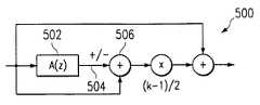
이퀄라이저 기술 분야의 숙련된 기술자들에게, 신규한 원리를 적용하고 그와 같은 특별한 구성 요소들을 요구에 따라 구성 및 이용하는 데에 필요한 정보들을 제공하기 위해, 본 발명이 매우 상세하게 설명되었다. 상기 설명들로부터 볼 때, 본 발명이 종래 기술에 비해 구성 및 동작에 있어서 상당한 진보성을 나타낸다는 것은 명백할 것이다. 그러나, 본 명세서에서는 본 발명의 특정한 실시예들이 상세하게 설명되었지만, 첨부된 특허 청구 범위에 정의된 것과 같이, 본 발명의 취지 및 범위를 벗어나지 않는 다양한 변경, 수정 및 대체가 이루어질 수 있음을 알 수 있을 것이다. 예를 들어, 도 5는 본 기술 분야의 숙련된 기술자들에게 공지되어 있는 1차 쉐프 필터를 구현하는 데에 적합한 구조물(500)을 도시하고 있다. 많은 응용에서, 쉐프 필터는 오디오 대역의 중앙에서 0㏈로 수렴하며, 대역폭 가장자리에서는 소정의 유한값으로 된다. 도 5의 A(z) 블록(502)은 아래의 수학식 (10)에 의해 표현되는 형태를 가질 것이다.The present invention has been described in great detail in order to provide those skilled in the equalizer art with the information necessary to apply the novel principles and to configure and use such special components as required. From the above descriptions, it will be apparent that the present invention represents a significant advance in construction and operation over the prior art. However, while certain embodiments of the invention have been described in detail herein, it will be appreciated that various changes, modifications, and substitutions can be made therein without departing from the spirit and scope of the invention as defined in the appended claims. There will be. For example, FIG. 5 illustrates astructure 500 suitable for implementing a primary chef filter known to those skilled in the art. In many applications, the chef filter converges to 0 Hz at the center of the audio band and reaches a predetermined finite value at the bandwidth edge. A (z) block 502 of FIG. 5 may have a form represented by Equation (10) below.

Figure 112001000882744-pat00052

이 때, β는 수학식 (1) 및 (3)에서 정의된 것과 같다. 합산 노드(506)로 진입하는 브랜치(504)의 부호는 저대역(전형적으로 20㎐ 내지 수백 ㎐) 세프에서는 정(+)이고 고대역(5㎑ 이상)에서는 부(-)이어야 한다. 구조물(500)은 범용 그래퍼메트릭 EQ 구조물(300) 내에서 구현되어, 이동 가능 코너 베이스 및 트레블 제어를 허용할 수 있다. 1 또는 -1의 제어 비트 또는 배수 인수를 다운로드함으로써 부호가 조절될 수 있는 한편, β파라미터는 1차 쉐프 필터의 코너 주파수를 조절하도록 구성될 수 있다. 또한, 차단 영역 내의 β값은 전술한 방법을 이용하여 근사될 수 있다. 또한, 본 기술 분야의 숙련된 기술자들은 본 발명이 통상적인 벨형 EQ 필터에 이용되어 트레블 및 베이스 영역에서의 그래픽 이퀄라이제이션을 수용하도록 구성될 수도 있음을 알 것이다. 이러한 접근은, 쉐프 필터와는 달리 로우 엔드 응답이 종래의 벨형 필터에서처럼 롤 오프하기 때문에, 과잉의 베이스 에너지를 소형 확성기로 유도하는 데에 유용한 것으로 입증될 것이다.At this time, β is as defined in equations (1) and (3). The sign of thebranch 504 entering the summingnode 506 should be positive in the low band (typically 20 Hz to several hundred Hz) chef and negative in the high band (greater than 5 Hz).Structure 500 may be implemented within general purposegraphical EQ structure 300 to allow for movable corner base and treble control. While the sign can be adjusted by downloading a control bit or a multiple factor of 1 or -1, the β parameter can be configured to adjust the corner frequency of the first order chef filter. Also, the β value in the blocking region can be approximated using the above-described method. In addition, those skilled in the art will appreciate that the present invention may be used to accommodate graphic equalization in the treble and bass regions, as used in conventional bell type EQ filters. This approach will prove useful for inducing excess bass energy into a small loudspeaker, as the low end response rolls off as in a conventional bell-shaped filter unlike a chef filter.

본 발명의 그래퍼메트릭 이퀄라이저는 팝(pop), 클릭, 또는 다른 불필요한 사운드와 같은 들려오는 인위적인 가청 잡음 없이 필터 구조에 파라미터들을 인가하도록 사용자 입력을 타이밍하고 연화(softening) 함수를 통해 필터 파라미터들을 증가시킴으로써 불필요한 인위적인 가청 잡음 없이 이퀄라이제이션을 제공한다.The graphermetric equalizer of the present invention is capable of timing user input to apply parameters to the filter structure without audible audible audible noises such as pops, clicks, or other unwanted sounds, and by increasing the filter parameters through a softening function. Provides equalization without unnecessary artificial audible noise.

Claims (23)

Translated fromKorean
삭제delete그래퍼메트릭 이퀄라이저(graphametric equalizer)에 있어서,In the graphametric equalizer,미리 정해진 오디오 대역폭에 걸친 복수의 이퀄라이징 필터;A plurality of equalizing filters over a predetermined audio bandwidth;데이터 프로세서;Data processor;상기 데이터 프로세서와 통신하는 데이터 입력 장치;A data input device in communication with the data processor;상기 데이터 프로세서를 지시하는 변환 함수(translation function) 알고리즘 소프트웨어;Translation function algorithmic software for directing the data processor;상기 데이터 프로세서를 지시하는 연화 함수(softening function) 알고리즘 소프트웨어; 및Softening function algorithm software instructing the data processor; And데이터 저장부 - 상기 데이터 저장부에는, 이산 중심 주파수 데이터, 이산 대역폭 데이터 및 이산 이득 데이터가 저장되고 상기 데이터 프로세서에 공급되어, 상기 변환 함수 알고리즘 소프트웨어에 의해 지시된 상기 데이터 프로세서가 상기 이산 중심 주파수 데이터, 상기 이산 대역폭 데이터 및 상기 이산 이득 데이터들 간에 알고리즘적으로 정의된 관계를 이용하여 필터 파라미터를 자동으로 결정할 수 있어서 상기 복수의 이퀄라이징 필터들이 상기 필터 파라미터에 의해 재특성화될 수 있고, 이산 증가 데이터가 저장되고 상기 데이터 프로세서에 공급되어, 상기 데이터 프로세서가 상기 복수의 이퀄라이징 필터가 실질적으로 인위적인 가청 잡음없이 재특성화될 수 있도록 이득 증가분 파라미터를 자동적으로 결정할 수 있음 - 을 포함하고,Data storage unit-In the data storage unit, discrete center frequency data, discrete bandwidth data and discrete gain data are stored and supplied to the data processor such that the data processor indicated by the transform function algorithm software causes the discrete center frequency data. Filter parameters can be automatically determined using an algorithmically defined relationship between the discrete bandwidth data and the discrete gain data such that the plurality of equalizing filters can be recharacterized by the filter parameter, Stored and supplied to the data processor, wherein the data processor can automatically determine a gain increment parameter such that the plurality of equalizing filters can be recharacterized without substantially artificial audible noise;상기 이퀄라이징 필터들 각각은, 0㏈ 미만의 차단 영역(cut region)에 대해서는 미리 정해진 대역폭 및 미리 정해진 피크 이득에 의존하고 0㏈ 초과의 부스트 영역(boost region)에 대해서는 미리 정해진 대역폭에만 의존하는 승수(multiplier)를 갖는 전역 통과 필터를 포함하는 그래퍼메트릭 이퀄라이저.Each of the equalizing filters depends on a predetermined bandwidth and a predetermined peak gain for a cut region less than 0 dB and a multiplier that depends only on a predetermined bandwidth for a boost region greater than 0 dB. Graphermetric equalizer with global pass filter with multiplier.제2항에 있어서,The method of claim 2,상기 변환 함수 알고리즘 소프트웨어는 0㏈ 미만의 차단 영역에서는 상기 전역 통과 필터 승수에 근사하도록 구성되고, 승수 근사 함수
Figure 112001000882744-pat00053
를 포함하며, 여기서 상기 β는 상기 전역 통과 필터 승수이고, BW는 사용자 선택 전역 통과 필터 대역폭이고, Fs는 사용자 선택 샘플링 주파수이며, k는 이퀄라이징 필터의 사용자 선택 피크 이득인 그래퍼메트릭 이퀄라이저.The transform function algorithm software is configured to approximate the global pass filter multiplier in a blocking region of less than 0 dB, and a multiplier approximation function.
Figure 112001000882744-pat00053
Wherein β is the all-pass filter multiplier, BW is the user-selected all-pass filter bandwidth, Fs is the user-selected sampling frequency, and k is the user-selected peak gain of the equalizing filter.제2항에 있어서,The method of claim 2,상기 변환 함수 알고리즘 소프트웨어는 또한 상수 x의 근사적인 역수값을 구하도록 구성되고, 역수값 근사 함수
Figure 112007019876776-pat00054
*2-n-2-r*2-2n-1+2-n-1를 포함하며, 여기서 s는 정상적으로 약 0.5 내지 약 0.6의 값을 가질 스케일링 파라미터로서 각각의 응용에서 상수값이며, n의 값은 상수 x의 최상위 숫자로 표현되며, r=x-2n인 그래퍼메트릭 이퀄라이저.
The transform function algorithm software is further configured to find an approximate reciprocal of the constant x, and the reciprocal approximation function
Figure 112007019876776-pat00054
* 2-n-2 -r * 2-2n-1 +2-n-1 , where s is a scaling parameter that will normally have a value of about 0.5 to about 0.6 and is a constant value in each application, The value is represented by the highest digit of the constant x, where r = x-2n .
디지털 그래퍼메트릭 이퀄라이저에 있어서,In the Digital Graphermetric Equalizer,미리 정해진 오디오 대역폭에 걸친 복수의 이퀄라이징 필터-상기 이퀄라이징 필터 각각은, 0㏈ 미만의 차단 영역에 대해서는 소망의 대역폭 및 소망의 피크 이득에 의존하고 0㏈ 초과의 부스트 영역에 대해서는 소망의 대역폭에만 의존하는 가변 승수를 가짐-; 및A plurality of equalizing filters over a predetermined audio bandwidth, each of the equalizing filters relying on the desired bandwidth and desired peak gain for a cutoff region of less than 0 Hz and only on the desired bandwidth for a boost region above 0 Hz. Has a variable multiplier; And소망의 피크 이득 k의 근사적인 역수값을 생성하도록 구성되고 역수 근사 함수
Figure 112006002619828-pat00055
*2-n-2-r*2-2n-1+2-n-1를 포함하는 변환 알고리즘 소프트웨어-여기서, s는 통상적으로 약 0.5 내지 약 0.6의 값을 가질 스케일링 파라미터로서 각각의 응용에서 상수값이며, n의 값은 소망의 피크 이득 k의 최상위 숫자로 표현되며, r = k - 2n임-
An inverse approximation function configured to produce an approximate reciprocal of the desired peak gain k
Figure 112006002619828-pat00055
Transform algorithm software comprising * 2-n-2 -r * 2-2n-1 +2-n-1 , where s is a scaling parameter that will typically have a value of about 0.5 to about 0.6, constant in each application Value, the value of n is represented by the most significant number of the desired peak gain k, where r = k-2n-
를 포함하는 디지털 그래퍼메트릭 이퀄라이저.Includes a digital grapher metric equalizer.
제5항에 있어서,The method of claim 5,상기 변환 알고리즘 소프트웨어는 또한 0㏈ 미만의 차단 영역에서 전역 통과 필터 가변 승수에 근사하도록 구성되며, tan(πBW/Fs)≤약 0.0625에 대하여 승수 근 사 함수
Figure 112001000882744-pat00056
를 포함하며, 여기서 β는 전역 통과 필터 승수이고, BW는 미리 정해진 전역 통과 필터 대역폭이고, Fs는 샘플링 주파수이며, k는 이퀄라이징 필터의 미리 정해진 피크 이득인 디지털 그래퍼메트릭 이퀄라이저.
The transform algorithm software is further configured to approximate a global pass filter variable multiplier in a blocking region of less than 0 dB, and a multiplier approximation function for tan (πBW / Fs ) ≤ about 0.0625.
Figure 112001000882744-pat00056
Wherein β is the all-pass filter multiplier, BW is the predetermined all-pass filter bandwidth, Fs is the sampling frequency, and k is the predetermined peak gain of the equalizing filter.
제5항에 있어서,The method of claim 5,상기 변환 알고리즘 소프트웨어는 또한 0㏈ 미만의 상기 차단 영역에서 상기 전역 통과 필터 가변 승수에 근사하도록 구성되고, tan(πBW/Fs)≤약 0.0625에 대하여 승수 근사 함수 β= [tan(Ω/2)-1]/[tan(Ω/2)+1]를 포함하며, 여기서 β는 전역 통과 필터 승수이고, BW는 미리 정해진 전역 통과 필터 대역폭이고, Fs는 미리 정해진 샘플링 주파수이며, k는 이퀄라이징 필터의 미리 정해진 피크 이득인 디지털 그래퍼메트릭 이퀄라이저.The transform algorithm software is further configured to approximate the all-pass filter variable multiplier in the cutoff region less than 0 Hz, and a multiplier approximation function β = [tan (Ω / 2) for tan (πBW / Fs ) ≦ about 0.0625. -1] / [tan (Ω / 2) +1], where β is the all-pass filter multiplier, BW is the predetermined all-pass filter bandwidth, Fs is the predetermined sampling frequency, and k is the equalizing filter Digital peak metric equalizer with a predetermined peak gain.그래퍼메트릭 이퀄라이저에 있어서,In the metric metric equalizer,복수의 오디오 대역폭에 걸친 복수의 디지털 이퀄라이징 필터 -상기 이퀄라이징 필터 각각은, 0㏈ 미만의 차단 영역에 대해서는 소망의 대역폭 및 소망의 피크 이득에 의존하고 0㏈ 초과의 부스트 영역에 대해서는 소망의 대역폭에만 의존하는 가변 승수 파라미터를 가짐-;Multiple Digital Equalizing Filters Across Multiple Audio Bandwidths-Each of the Equalizing Filters Relies on Desired Bandwidth and Desired Peak Gain for Cutoff Regions Less Than 0 Hz and Only Desired Bandwidth for Boost Regions Above 0 Hz Having a variable multiplier parameter;소망의 대역폭 및 소망의 피크 이득을 변환하고, 상기 복수의 디지털 이퀄라이징 필터가 소망의 승수로 재특성화되도록 가변 승수 파라미터를 생성하는 변환 수단; 및Converting means for converting a desired bandwidth and a desired peak gain and generating a variable multiplier parameter such that the plurality of digital equalizing filters are recharacterized by a desired multiplier; And사용자 입력을 타이밍하고, 상기 복수의 디지털 이퀄라이징 필터가 실질적으로 인위적인 가청 잡음없이 재특성화될 수 있도록 필터 파라미터를 증가시키는 연화 수단Softening means for timing user input and increasing filter parameters such that the plurality of digital equalizing filters can be recharacterized without substantially artificial audible noise을 포함하는 그래퍼메트릭 이퀄라이저.Grapher metric equalizer that includes.제8항에 있어서,The method of claim 8,상기 변환 수단은,
Figure 112006002619828-pat00057
*2-n-2-r*2-2n-1+2-n-1의 관계를 이용하여 소망의 피크 이득 k에 대한 근사적인 역수값을 생성하도록 구성된 알고리즘 소프트웨어를 포함하며, 여기서 s는 통상적으로 약 0.5 내지 약 0.6의 값을 갖는 스케일링 파라미터로서 각각의 응용에 대해 상수이며, n의 값은 소망의 피크 이득 k의 최상위 숫자로 표현되고, r = k-2n인 그래퍼메트릭 이퀄라이저.
The conversion means,
Figure 112006002619828-pat00057
Includes algorithmic software configured to produce an approximate reciprocal of the desired peak gain k using the relationship of * 2-n-2 -r * 2-2n-1 +2-n-1 , where s is typical And is a constant for each application as a scaling parameter having a value of about 0.5 to about 0.6, wherein the value of n is represented by the most significant digit of the desired peak gain k, where r = k-2n .
제9항에 있어서,The method of claim 9,상기 변환 수단은 또한 0㏈ 미만의 차단 영역에서 전역 통과 필터 가변 승수 파라미터를 생성하도록 구성되며, tan(πBW/Fs)≤약 0.0625에 대해서 승수 근사 함수
Figure 112001000882744-pat00058
를 포함하며,
The converting means is further configured to generate a global pass filter variable multiplier parameter in a blocking region of less than 0 dB, and a multiplier approximation function for tan (πBW / Fs ) ≦ about 0.0625.
Figure 112001000882744-pat00058
Including;
여기서 β는 전역 통과 필터 승수이고, BW는 미리 정해진 전역 통과 필터 대 역폭이고, Fs는 미리 정해진 샘플링 주파수이며, k는 상기 이퀄라이징 필터의 피크 이득인 그래퍼메트릭 이퀄라이저.Wherein β is an all pass filter multiplier, BW is a predetermined all pass filter bandwidth, Fs is a predetermined sampling frequency, and k is a peak gain of the equalizing filter.
제8항에 있어서, 상기 연화 수단은, 이퀄라이저 이득 변동을 선형 공간에서약 44.1㎑의 샘플링 속도에 대해 약 0.05 내지 약 0.06 범위, 매 64개의 샘플마다 한 번을 초과하지 않게 제한하도록 구성되는 그래퍼메트릭 이퀄라이저.The graphimetric of claim 8, wherein the softening means is configured to limit the equalizer gain variation in a linear space to a sampling rate of about 44.1 kHz in a range from about 0.05 to about 0.06, no more than once per every 64 samples. Equalizer.삭제delete디지털 이퀄라이저 제어 방법에 있어서,In the digital equalizer control method,가변 파라미터 승수를 갖는 전역 통과 필터 기반 이퀄라이제이션 필터를 제공하는 단계;Providing an all pass filter based equalization filter having a variable parameter multiplier;상기 이퀄라이제이션 필터와 연관된 전역 통과 필터에 대하여 사용자 선택 이득 및 사용자 선택 대역폭을 수신하는 단계;Receiving a user selected gain and a user selected bandwidth for an all pass filter associated with the equalization filter;관계식
Figure 112006002619828-pat00059
*2-n-2-r*2-2n-1+2-n-1을 이용하여 사용자 선택 피크 이득에 대한 근사적인 역수값을 생성하는 단계 -여기서, s는 통상적으로 약 0.5 내지 약 0.6의 값을 갖는 스케일링 파라미터로서 각각의 응용에서 상수이며, n의 값은 소망의 피크 이득 k의 최상위 숫자로 표현되고, r = k-2n임-;
Relation
Figure 112006002619828-pat00059
Generating an approximate reciprocal of the user-selected peak gain with * 2-n-2 -r * 2-2n-1 +2-n-1 , where s is typically from about 0.5 to about 0.6 A scaling parameter with a value, which is constant in each application, where the value of n is represented by the most significant number of the desired peak gain k, where r = k-2n ;
tan(πBW/Fs)≤약 0.0625에 대해 β
Figure 112006002619828-pat00066
tan(πBW/Fs)/log2(3)ㆍk로 표현되는 승수 근사 함수를 통해, 상기 사용자 선택 이득 및 사용자 선택 대역폭을 전역 통과 필터에 대한 소망의 제1 승수 파라미터 β로 변환하는 단계 -여기서 β는 전역 통과 필터 승수이고, BW는 미리 정해진 전역 통과 필터 대역폭이고, Fs는 샘플링 주파수이며, k는 이퀄라이징 필터의 미리 정해진 피크 이득임-; 및
β for tan (πBW / Fs ) ≤ about 0.0625
Figure 112006002619828-pat00066
converting the user-selected gain and user-selected bandwidth into a desired first multiplier parameter β for the all-pass filter through a multiplier approximation function expressed as tan (πBW / Fs ) / log2 (3) · k − Wherein β is an all-pass filter multiplier, BW is a predetermined all-pass filter bandwidth, Fs is a sampling frequency, and k is a predetermined peak gain of the equalizing filter; And
상기 이퀄라이징 필터가 0㏈ 미만의 미리 정해진 차단 영역에서 부(-)의 이득을 달성할 수 있도록, 상기 전역 통과 필터를 통해 소망의 입력 신호를 처리하는 단계Processing the desired input signal through the all-pass filter so that the equalizing filter can achieve negative gain in a predetermined cutoff region of less than 0 dB.를 포함하는 디지털 이퀄라이저 제어 방법.Digital equalizer control method comprising a.
제13항에 있어서,The method of claim 13,tan(πBW/Fs)≤약 0.0625일 때, 상기 이퀄라이징 필터가 0㏈ 미만의 미리 정해진 차단 영역에서 소망의 입력 신호에 대해 부의 이득을 달성할 수 있도록, β= [tan(Ω/2)-k]/[tan(Ω/2)+k]-여기서 Ω는 사용자 선택 대역폭임-로 표현되는 승수 근사 함수를 통해, 상기 사용자 선택 이득 및 사용자 선택 대역폭을 상기 전역 통과 필터에 대한 소망의 제2 전역 통과 필터 승수 파라미터 β로 변환하는 단계When tan (πBW / Fs ) ≤ about 0.0625, β = [tan (Ω / 2) − so that the equalizing filter can achieve a negative gain for the desired input signal in a predetermined cutoff region of less than 0 Hz. k] / [tan (Ω / 2) + k], where Ω is a user-selected bandwidth, through a multiplier approximation function to express the user-selected gain and user-selected bandwidth with the desired second for the allpass filter. Converting to the global pass filter multiplier parameter β를 더 포함하는 디지털 이퀄라이저 제어 방법.Digital equalizer control method further comprising.제13항에 있어서,The method of claim 13,상기 전역 통과 필터와 연관된 상기 이퀄라이징 필터에 대한 사용자 선택 중심 주파수를 수신하고, 상기 이퀄라이징 필터가 2차 전역 통과 필터를 통해 실현될 수 있도록, 상기 사용자 선택 중심 주파수를 제2 가변 전역 통과 필터 승수 파라미터로 변환하는 단계Receive a user-selected center frequency for the equalizing filter associated with the all-pass filter and convert the user-selected center frequency into a second variable all-pass filter multiplier parameter such that the equalizing filter can be realized through a second order all-pass filter. Steps to convert를 더 포함하는 디지털 이퀄라이저 제어 방법.Digital equalizer control method further comprising.제13항에 있어서,The method of claim 13,입력 신호가 0㏈ 초과의 미리 정해진 부스트 영역에 있는 경우, 상기 이퀄라이저 필터가 소망의 입력 신호에 대해 정(+)의 이득을 달성할 수 있도록, β= [tan(Ω/2)-1]/[tan(Ω/2)+1]로 표현되는 승수 근사 함수를 통해, 상기 사용자 선택 대역폭을 상기 전역 통과 필터에 대한 소망의 전역 통과 필터에 대한 제2 승수 파라미터 β로 변환하는 단계If the input signal is in a predetermined boost region greater than 0 Hz, β = [tan (Ω / 2) -1] / so that the equalizer filter can achieve a positive gain for the desired input signal. converting the user-selected bandwidth into a second multiplier parameter β for the desired allpass filter for the allpass filter, via a multiplier approximation function expressed as [tan (Ω / 2) +1]를 더 포함하는 디지털 이퀄라이저 제어 방법.Digital equalizer control method further comprising.디지털 이퀄라이저 제어 방법에 있어서,In the digital equalizer control method,전역 통과 필터 기반 이퀄라이제이션 필터를 제공하는 단계;Providing an all pass filter based equalization filter;사용자 선택 중심 주파수, 사용자 선택 대역폭 및 사용자 선택 이득 설정을 수신하는 단계;Receiving a user selected center frequency, a user selected bandwidth and a user selected gain setting;상기 사용자 선택 이득 설정을 위한 근사적인 역수값을 생성하는 단계;Generating an approximate reciprocal value for setting the user select gain;상기 사용자 선택 이득 설정을 위한 근사적인 역수값에 부분적으로 기초하여, tan(Ω/2)≤0.0625-여기서, Ω는 사용자 선택 대역폭임-인 영역에서 제1 전역 통과 필터 승수 파라미터를 생성하는 단계;Generating a first allpass filter multiplier parameter in a region where tan (Ω / 2) ≤0.0625, where Ω is a user-selected bandwidth, based in part on the approximate reciprocal value for setting the user select gain;상기 제1 필터 승수 파라미터를 통해 전역 통과 필터를 특성화하는 단계; 및Characterizing an all-pass filter through the first filter multiplier parameter; And상기 이퀄라이제이션 필터를 통해 미리 정해진 입력 신호를 처리하여, 0㏈ 미만의 소망의 차단 영역에서 부의 이득을 달성하는 단계Processing a predetermined input signal through the equalization filter to achieve negative gain in a desired cutoff region of less than 0 dB를 포함하는 디지털 이퀄라이저 제어 방법.Digital equalizer control method comprising a.제17항에 있어서,The method of claim 17,인위적인 가청 잡음이 실질적으로 감소되도록, 상기 제1 승수 파라미터를 통해 상기 전역 통과 필터의 재특성화를 타이밍하고 증가시키는 단계Timing and increasing the recharacterization of the all-pass filter through the first multiplier parameter such that artificial audible noise is substantially reduced를 더 포함하는 디지털 이퀄라이저 제어 방법.Digital equalizer control method further comprising.제17항에 있어서,The method of claim 17,tan(Ω/2) > 약 0.0625인 영역에서 제2 전역 통과 필터 승수 파라미터를 생성하는 단계;generating a second all-pass filter multiplier parameter in the region tan (Ω / 2)> about 0.0625;상기 제2 필터 승수 파라미터를 통해 전역 통과 필터를 다시 특성화하는 단계; 및Recharacterizing an all-pass filter via the second filter multiplier parameter; And미리 정해진 입력 신호를 상기 이퀄라이제이션 필터를 통해 처리하여, 0㏈ 미만의 소망의 차단 영역에서 부의 이득을 달성하는 단계Processing a predetermined input signal through the equalization filter to achieve negative gain in a desired cutoff region of less than 0 dB를 더 포함하는 디지털 이퀄라이저 제어 방법.Digital equalizer control method further comprising a.제19항에 있어서,The method of claim 19,인위적인 가청 잡음이 실질적으로 감소되도록, 상기 제2 승수 파라미터를 통해 상기 전역 통과 필터의 재특성화를 타이밍하고 증가시키는 단계Timing and increasing the recharacterization of the all-pass filter through the second multiplier parameter such that artificial audible noise is substantially reduced를 더 포함하는 디지털 이퀄라이저 제어 방법.Digital equalizer control method further comprising.제17항에 있어서,The method of claim 17,상기 사용자 선택 중심 주파수에 기초하여 제3 전역 통과 필터 승수 파라미터를 생성하는 단계;Generating a third allpass filter multiplier parameter based on the user selected center frequency;상기 제3 승수 파라미터를 통해 상기 전역 통과 필터를 다시 특성화하는 단계; 및Recharacterizing the allpass filter through the third multiplier parameter; And미리 정해진 입력 신호를 상기 이퀄라이제이션 필터를 통해 처리하여, 0㏈ 초과의 소망의 부스트 영역에서 정(+)의 이득을 달성하는 단계Processing a predetermined input signal through the equalization filter to achieve a positive gain in the desired boost region above 0 dB를 더 포함하는 디지털 이퀄라이저 제어 방법.Digital equalizer control method further comprising.제21항에 있어서,The method of claim 21,인위적인 가청 잡음이 실질적으로 감소되도록, 상기 승수 파라미터를 통해 상기 전역 통과 필터의 재특성화를 타이밍하고 증가시키는 단계Timing and increasing the recharacterization of the all-pass filter through the multiplier parameter such that artificial audible noise is substantially reduced를 더 포함하는 디지털 이퀄라이저 제어 방법.Digital equalizer control method further comprising.제2항에 있어서,The method of claim 2,상기 데이터 저장부는 이산 타이밍 데이터(discrete timing data)를 또한 저장하고, 상기 그래퍼메트릭 이퀄라이저는 타이밍 파라미터들에 또한 기초해서 이득 증가분 파라미터를 자동으로 결정하기 위한 연화 함수 알고리즘 소프트웨어를 더욱 포함하는 그래퍼메트릭 이퀄라이저.The data store also stores discrete timing data, and the graphermetric equalizer further comprises a softening function algorithm software for automatically determining gain increment parameters based on timing parameters as well.
KR1020010002047A2000-01-142001-01-13Digital graphametric equalizerExpired - Fee RelatedKR100745850B1 (en)

Applications Claiming Priority (2)

Application NumberPriority DateFiling DateTitle
US09/481,851US7058126B1 (en)2000-01-142000-01-14Digital graphametric equalizer
US09/481,8512000-01-14

Publications (2)

Publication NumberPublication Date
KR20010076265A KR20010076265A (en)2001-08-11
KR100745850B1true KR100745850B1 (en)2007-08-02

Family

ID=23913639

Family Applications (1)

Application NumberTitlePriority DateFiling Date
KR1020010002047AExpired - Fee RelatedKR100745850B1 (en)2000-01-142001-01-13Digital graphametric equalizer

Country Status (6)

CountryLink
US (1)US7058126B1 (en)
EP (1)EP1117179B1 (en)
JP (1)JP2001257629A (en)
KR (1)KR100745850B1 (en)
AT (1)ATE348448T1 (en)
DE (1)DE60125072T2 (en)

Families Citing this family (8)

* Cited by examiner, † Cited by third party
Publication numberPriority datePublication dateAssigneeTitle
US6643323B1 (en)*2000-02-022003-11-04Texas Instruments IncorporatedDigital filtering method
US7123728B2 (en)*2001-08-152006-10-17Apple Computer, Inc.Speaker equalization tool
US7328412B1 (en)*2003-04-052008-02-05Apple Inc.Method and apparatus for displaying a gain control interface with non-linear gain levels
US7610553B1 (en)*2003-04-052009-10-27Apple Inc.Method and apparatus for reducing data events that represent a user's interaction with a control interface
FR2855931A1 (en)*2003-06-052004-12-10Claude CarpentierPhase equalization device for stereophonic sound reproduction system, has cells, each of which includes all pass filters inserted on left and right channels, where tuning frequency, width and gain of cells are independently varying
GB2457705A (en)*2008-02-222009-08-26Apple Dynamics Intellectual PrSignal processing means and a method of signal processing
EP2182633A1 (en)2008-10-302010-05-05University College CorkCircuits for ultrasonic transducers
DE202014101373U1 (en)*2014-03-252015-06-29Bernhard Schwede Equalizer for equalizing a sound mix and audio system with such an equalizer

Citations (5)

* Cited by examiner, † Cited by third party
Publication numberPriority datePublication dateAssigneeTitle
JPH0590856A (en)*1991-09-261993-04-09Fujitsu Ten LtdDevice for automatically correcting acoustic frequency characteristics
JPH05152982A (en)*1991-11-281993-06-18Kenwood CorpTransmission frequency characteristic correcting device
JPH0653767A (en)*1992-07-281994-02-25Clarion Co LtdControl circuit for equalizer characteristic for sound field correction and control method
US5541866A (en)*1991-11-281996-07-30Kabushiki Kaisha KenwoodDevice for correcting frequency characteristic of sound field
EP0932253A2 (en)1998-01-151999-07-28Texas Instruments IncorporatedSoft gain update method & apparatus

Family Cites Families (2)

* Cited by examiner, † Cited by third party
Publication numberPriority datePublication dateAssigneeTitle
JP2840155B2 (en)*1992-03-191998-12-24富士通株式会社 Equalization method
US5687104A (en)*1995-11-171997-11-11Motorola, Inc.Method and apparatus for generating decoupled filter parameters and implementing a band decoupled filter

Patent Citations (5)

* Cited by examiner, † Cited by third party
Publication numberPriority datePublication dateAssigneeTitle
JPH0590856A (en)*1991-09-261993-04-09Fujitsu Ten LtdDevice for automatically correcting acoustic frequency characteristics
JPH05152982A (en)*1991-11-281993-06-18Kenwood CorpTransmission frequency characteristic correcting device
US5541866A (en)*1991-11-281996-07-30Kabushiki Kaisha KenwoodDevice for correcting frequency characteristic of sound field
JPH0653767A (en)*1992-07-281994-02-25Clarion Co LtdControl circuit for equalizer characteristic for sound field correction and control method
EP0932253A2 (en)1998-01-151999-07-28Texas Instruments IncorporatedSoft gain update method & apparatus

Also Published As

Publication numberPublication date
DE60125072D1 (en)2007-01-25
US7058126B1 (en)2006-06-06
EP1117179B1 (en)2006-12-13
EP1117179A2 (en)2001-07-18
ATE348448T1 (en)2007-01-15
EP1117179A3 (en)2004-01-14
JP2001257629A (en)2001-09-21
KR20010076265A (en)2001-08-11
DE60125072T2 (en)2007-05-03

Similar Documents

PublicationPublication DateTitle
EP1121834B1 (en)Hearing aids based on models of cochlear compression
US8199933B2 (en)Calculating and adjusting the perceived loudness and/or the perceived spectral balance of an audio signal
JP6351538B2 (en) Multiband signal processor for digital acoustic signals.
US6370255B1 (en)Loudness-controlled processing of acoustic signals
US7254242B2 (en)Acoustic signal processing apparatus and method, and audio device
US20030216907A1 (en)Enhancing the aural perception of speech
Rämö et al.High-precision parallel graphic equalizer
EP2209116A1 (en)High range interpolation device and high range interpolation method
EP2002429A1 (en)Calculating and adjusting the perceived loudness and/or the perceived spectral balance of an audio signal
WO2015111084A2 (en)Dynamic range compression with low distortion for use in hearing aids and audio systems
JP5216125B2 (en) Dynamic acoustic optimization method and apparatus
KR20040035749A (en)Bandwidth extension of a sound signal
KR100745850B1 (en)Digital graphametric equalizer
US20030091207A1 (en)Dynamic range analog to digital converter suitable for hearing aid applications
US20040114769A1 (en)Method of modifying low frequency components of a digital audio signal
JP4368917B2 (en) Sound playback device
JP7576632B2 (en) Bass Enhancement for Speakers
JP3322479B2 (en) Audio equipment
JP3109389B2 (en) Adaptive filter system
JP3445909B2 (en) Audio apparatus and volume adjustment method thereof
CN117616780A (en)Adaptive filter bank using scale dependent nonlinearity for psychoacoustic frequency range expansion
WO2004107573A1 (en)Audio quality adjustment device
Kates et al.The dynamic gammawarp auditory filterbank
KR100684029B1 (en) Method for generating harmonics using Fourier transform and apparatus therefor, method for generating harmonics by down sampling, apparatus for same and method for sound correction and apparatus for same
US6643323B1 (en)Digital filtering method

Legal Events

DateCodeTitleDescription
PA0109Patent application

St.27 status event code:A-0-1-A10-A12-nap-PA0109

PG1501Laying open of application

St.27 status event code:A-1-1-Q10-Q12-nap-PG1501

A201Request for examination
P11-X000Amendment of application requested

St.27 status event code:A-2-2-P10-P11-nap-X000

P13-X000Application amended

St.27 status event code:A-2-2-P10-P13-nap-X000

PA0201Request for examination

St.27 status event code:A-1-2-D10-D11-exm-PA0201

D13-X000Search requested

St.27 status event code:A-1-2-D10-D13-srh-X000

D14-X000Search report completed

St.27 status event code:A-1-2-D10-D14-srh-X000

E902Notification of reason for refusal
PE0902Notice of grounds for rejection

St.27 status event code:A-1-2-D10-D21-exm-PE0902

T11-X000Administrative time limit extension requested

St.27 status event code:U-3-3-T10-T11-oth-X000

E13-X000Pre-grant limitation requested

St.27 status event code:A-2-3-E10-E13-lim-X000

P11-X000Amendment of application requested

St.27 status event code:A-2-2-P10-P11-nap-X000

P13-X000Application amended

St.27 status event code:A-2-2-P10-P13-nap-X000

E701Decision to grant or registration of patent right
PE0701Decision of registration

St.27 status event code:A-1-2-D10-D22-exm-PE0701

GRNTWritten decision to grant
PR0701Registration of establishment

St.27 status event code:A-2-4-F10-F11-exm-PR0701

PR1002Payment of registration fee

St.27 status event code:A-2-2-U10-U11-oth-PR1002

Fee payment year number:1

PG1601Publication of registration

St.27 status event code:A-4-4-Q10-Q13-nap-PG1601

G170Re-publication after modification of scope of protection [patent]
PG1701Publication of correction

St.27 status event code:A-5-5-P10-P19-oth-PG1701

Patent document republication publication date:20080417

Republication note text:Request for Correction Notice (Document Request)

Gazette number:1007458500000

Gazette reference publication date:20070802

PR1001Payment of annual fee

St.27 status event code:A-4-4-U10-U11-oth-PR1001

Fee payment year number:4

PR1001Payment of annual fee

St.27 status event code:A-4-4-U10-U11-oth-PR1001

Fee payment year number:5

PR1001Payment of annual fee

St.27 status event code:A-4-4-U10-U11-oth-PR1001

Fee payment year number:6

FPAYAnnual fee payment

Payment date:20130628

Year of fee payment:7

PR1001Payment of annual fee

St.27 status event code:A-4-4-U10-U11-oth-PR1001

Fee payment year number:7

FPAYAnnual fee payment

Payment date:20140627

Year of fee payment:8

PR1001Payment of annual fee

St.27 status event code:A-4-4-U10-U11-oth-PR1001

Fee payment year number:8

PR1001Payment of annual fee

St.27 status event code:A-4-4-U10-U11-oth-PR1001

Fee payment year number:9

FPAYAnnual fee payment

Payment date:20160629

Year of fee payment:10

PR1001Payment of annual fee

St.27 status event code:A-4-4-U10-U11-oth-PR1001

Fee payment year number:10

FPAYAnnual fee payment

Payment date:20170629

Year of fee payment:11

PR1001Payment of annual fee

St.27 status event code:A-4-4-U10-U11-oth-PR1001

Fee payment year number:11

FPAYAnnual fee payment

Payment date:20180628

Year of fee payment:12

PR1001Payment of annual fee

St.27 status event code:A-4-4-U10-U11-oth-PR1001

Fee payment year number:12

PR1001Payment of annual fee

St.27 status event code:A-4-4-U10-U11-oth-PR1001

Fee payment year number:13

R18-X000Changes to party contact information recorded

St.27 status event code:A-5-5-R10-R18-oth-X000

PC1903Unpaid annual fee

St.27 status event code:A-4-4-U10-U13-oth-PC1903

Not in force date:20200728

Payment event data comment text:Termination Category : DEFAULT_OF_REGISTRATION_FEE

PC1903Unpaid annual fee

St.27 status event code:N-4-6-H10-H13-oth-PC1903

Ip right cessation event data comment text:Termination Category : DEFAULT_OF_REGISTRATION_FEE

Not in force date:20200728


[8]ページ先頭

©2009-2025 Movatter.jp