KR100745765B1 - Spatial prediction device and method for image data, encoding device and method using same, Spatial prediction compensation device and method for image data, and decoding device and method using same - Google Patents
Spatial prediction device and method for image data, encoding device and method using same, Spatial prediction compensation device and method for image data, and decoding device and method using sameDownload PDFInfo
- Publication number
- KR100745765B1 KR100745765B1KR20060033582AKR20060033582AKR100745765B1KR 100745765 B1KR100745765 B1KR 100745765B1KR 20060033582 AKR20060033582 AKR 20060033582AKR 20060033582 AKR20060033582 AKR 20060033582AKR 100745765 B1KR100745765 B1KR 100745765B1
- Authority
- KR
- South Korea
- Prior art keywords
- pixel values
- spatial prediction
- adjacent blocks
- current block
- prediction mode
- Prior art date
- Legal status (The legal status is an assumption and is not a legal conclusion. Google has not performed a legal analysis and makes no representation as to the accuracy of the status listed.)
- Active
Links
Images


Classifications
- H—ELECTRICITY
- H04—ELECTRIC COMMUNICATION TECHNIQUE
- H04N—PICTORIAL COMMUNICATION, e.g. TELEVISION
- H04N19/00—Methods or arrangements for coding, decoding, compressing or decompressing digital video signals
- H04N19/85—Methods or arrangements for coding, decoding, compressing or decompressing digital video signals using pre-processing or post-processing specially adapted for video compression
- H—ELECTRICITY
- H04—ELECTRIC COMMUNICATION TECHNIQUE
- H04N—PICTORIAL COMMUNICATION, e.g. TELEVISION
- H04N19/00—Methods or arrangements for coding, decoding, compressing or decompressing digital video signals
- H04N19/10—Methods or arrangements for coding, decoding, compressing or decompressing digital video signals using adaptive coding
- H04N19/102—Methods or arrangements for coding, decoding, compressing or decompressing digital video signals using adaptive coding characterised by the element, parameter or selection affected or controlled by the adaptive coding
- H04N19/103—Selection of coding mode or of prediction mode
- H04N19/11—Selection of coding mode or of prediction mode among a plurality of spatial predictive coding modes
- H—ELECTRICITY
- H04—ELECTRIC COMMUNICATION TECHNIQUE
- H04N—PICTORIAL COMMUNICATION, e.g. TELEVISION
- H04N19/00—Methods or arrangements for coding, decoding, compressing or decompressing digital video signals
- H04N19/10—Methods or arrangements for coding, decoding, compressing or decompressing digital video signals using adaptive coding
- H04N19/102—Methods or arrangements for coding, decoding, compressing or decompressing digital video signals using adaptive coding characterised by the element, parameter or selection affected or controlled by the adaptive coding
- H04N19/124—Quantisation
- H—ELECTRICITY
- H04—ELECTRIC COMMUNICATION TECHNIQUE
- H04N—PICTORIAL COMMUNICATION, e.g. TELEVISION
- H04N19/00—Methods or arrangements for coding, decoding, compressing or decompressing digital video signals
- H04N19/10—Methods or arrangements for coding, decoding, compressing or decompressing digital video signals using adaptive coding
- H04N19/169—Methods or arrangements for coding, decoding, compressing or decompressing digital video signals using adaptive coding characterised by the coding unit, i.e. the structural portion or semantic portion of the video signal being the object or the subject of the adaptive coding
- H04N19/17—Methods or arrangements for coding, decoding, compressing or decompressing digital video signals using adaptive coding characterised by the coding unit, i.e. the structural portion or semantic portion of the video signal being the object or the subject of the adaptive coding the unit being an image region, e.g. an object
- H04N19/176—Methods or arrangements for coding, decoding, compressing or decompressing digital video signals using adaptive coding characterised by the coding unit, i.e. the structural portion or semantic portion of the video signal being the object or the subject of the adaptive coding the unit being an image region, e.g. an object the region being a block, e.g. a macroblock
- H—ELECTRICITY
- H04—ELECTRIC COMMUNICATION TECHNIQUE
- H04N—PICTORIAL COMMUNICATION, e.g. TELEVISION
- H04N19/00—Methods or arrangements for coding, decoding, compressing or decompressing digital video signals
- H04N19/50—Methods or arrangements for coding, decoding, compressing or decompressing digital video signals using predictive coding
- H04N19/59—Methods or arrangements for coding, decoding, compressing or decompressing digital video signals using predictive coding involving spatial sub-sampling or interpolation, e.g. alteration of picture size or resolution
- H—ELECTRICITY
- H04—ELECTRIC COMMUNICATION TECHNIQUE
- H04N—PICTORIAL COMMUNICATION, e.g. TELEVISION
- H04N19/00—Methods or arrangements for coding, decoding, compressing or decompressing digital video signals
- H04N19/50—Methods or arrangements for coding, decoding, compressing or decompressing digital video signals using predictive coding
- H04N19/593—Methods or arrangements for coding, decoding, compressing or decompressing digital video signals using predictive coding involving spatial prediction techniques
- H—ELECTRICITY
- H04—ELECTRIC COMMUNICATION TECHNIQUE
- H04N—PICTORIAL COMMUNICATION, e.g. TELEVISION
- H04N19/00—Methods or arrangements for coding, decoding, compressing or decompressing digital video signals
- H04N19/60—Methods or arrangements for coding, decoding, compressing or decompressing digital video signals using transform coding
- H04N19/61—Methods or arrangements for coding, decoding, compressing or decompressing digital video signals using transform coding in combination with predictive coding
- H—ELECTRICITY
- H04—ELECTRIC COMMUNICATION TECHNIQUE
- H04N—PICTORIAL COMMUNICATION, e.g. TELEVISION
- H04N19/00—Methods or arrangements for coding, decoding, compressing or decompressing digital video signals
- H04N19/80—Details of filtering operations specially adapted for video compression, e.g. for pixel interpolation
- H04N19/82—Details of filtering operations specially adapted for video compression, e.g. for pixel interpolation involving filtering within a prediction loop
Landscapes
- Engineering & Computer Science (AREA)
- Multimedia (AREA)
- Signal Processing (AREA)
- Compression Or Coding Systems Of Tv Signals (AREA)
- Compression Of Band Width Or Redundancy In Fax (AREA)
Abstract
Translated fromKoreanDescription
Translated fromKorean도 1은 종래의 공간상 예측에 대한 예측방향을 나타내는 일 예의 도면이다.1 is a diagram illustrating an example of a prediction direction for conventional spatial prediction.
도 2는 종래의 공간상 예측에 의해 파이프라인(pipeline) 처리가 이루어지지 못함을 설명하기 위한 도면이다.FIG. 2 is a diagram for explaining that pipeline processing is not performed by conventional spatial prediction.
도 3은 본 발명에 의한 화상 데이터의 공간상 예측 장치를 설명하기 위한 일 실시예의 블록도이다.3 is a block diagram of an embodiment for describing a spatial prediction apparatus of image data according to the present invention.
도 4는 4*4 블록의 화소값들 및 블록 주변의 화소값들의 일 예를 나타내는 도면이다.4 is a diagram illustrating an example of pixel values of a 4 * 4 block and pixel values around the block.
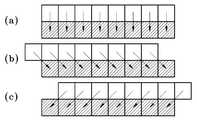
도 5는 1 차원 블록에 해당하는 8*1 블록에 대한 예측 방향의 일 예를 나타내는 도면이다.FIG. 5 is a diagram illustrating an example of a prediction direction for an 8 * 1 block corresponding to a 1-dimensional block.
도 6은 2차원 블록에 해당하는 4*4 블록에 대한 예측 방향의 일 예를 나타내는 도면이다.6 is a diagram illustrating an example of a prediction direction for a 4 * 4 block corresponding to a 2D block.
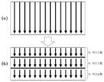
도 7은 에지 부분이 존재하는 화상의 1차원 블록에 대해 수직 방향으로 공간상 예측을 수행한 일 예를 나타낸 도면이다.FIG. 7 is a diagram illustrating an example of performing spatial prediction in a vertical direction with respect to a 1-dimensional block of an image in which an edge part exists.
도 8은 소정 라인들 단위마다 윗열 인접 블록들의 화소값들을 소정 기준값으로 대체하여 공간상 예측하는 일 예를 나타내는 도면이다.8 is a diagram illustrating an example of spatial prediction by replacing pixel values of upper row adjacent blocks with predetermined reference values for every predetermined line unit.
도 9는 3 라인들마다 윗열 인접 블록들의 화소값들을 소정 기준값으로 대체하여 공간상 예측하는 일 예를 나타내는 도면이다.9 is a diagram illustrating an example of spatial prediction by replacing pixel values of upper row adjacent blocks with predetermined reference values every three lines.
도 10은 화상의 에지 부분(예를 들어, 커서(cursor))에 의해 부호화시에 발생하는 에러의 확산을 차단하는 것을 예시하는 도면이다.FIG. 10 is a diagram illustrating blocking of spreading of an error occurring at the time of encoding by an edge portion (for example, a cursor) of an image.
도 11은 본 발명에 의한 화상 데이터의 부호화 장치를 설명하기 위한 일 실시예의 블록도이다.11 is a block diagram of an embodiment for explaining an apparatus for encoding image data according to the present invention.
도 12는 본 발명에 의한 화상 데이터의 공간상 예측 보상장치를 설명하기 위한 일 실시예의 블록도이다.12 is a block diagram of an embodiment for describing a spatial prediction compensation device of image data according to the present invention.
도 13은본 발명에 의한 화상 데이터의 복호화 장치를 설명하기 위한 일 실시예의 블록도이다.Fig. 13 is a block diagram of an embodiment for explaining an apparatus for decoding image data according to the present invention.
도 14는 본 발명에 의한 화상 데이터의 공간상 예측 방법을 설명하기 위한 일 실시예의 플로차트이다.14 is a flowchart of an embodiment for explaining a spatial prediction method of image data according to the present invention.
도 15는 본 발명에 의한 화상 데이터의 부호화 방법을 설명하기 위한 일 실시예의 플로차트이다.15 is a flowchart of an embodiment for explaining a method of encoding image data according to the present invention.
도 16은 본 발명에 의한 화상 데이터의 공간상 예측 보상방법을 설명하기 위한 일 실시예의 플로차트이다.16 is a flowchart of an exemplary embodiment for explaining a spatial prediction compensation method of image data according to the present invention.
도 17은 본 발명에 의한 화상 데이터의 복호화 방법을 설명하기 위한 일 실시예의 플로차트이다.17 is a flowchart of an embodiment for explaining a decoding method of image data according to the present invention.
〈도면의 주요 부호에 대한 간단한 설명〉<Brief description of the major symbols in the drawings>
100: 화소값 필터링부 120: 예측 모드 결정부100: pixel value filtering unit 120: prediction mode determination unit
140: 공간상 예측부 200: 화소값 필터링부140: spatial prediction unit 200: pixel value filtering unit
210: 예측 모드 결정부 220: 공간상 예측부210: prediction mode determiner 220: spatial prediction unit
230: 변환 및 양자화부 240: 비트열 생성부230: transform and quantizer 240: bit string generator
300: 공간상 예측 보상부 400: 비트열 복호화부300: spatial prediction compensation unit 400: bit string decoding unit
420: 역양자화 및 역변환부 440: 공간상 예측 보상부420: inverse quantization and inverse transform unit 440: spatial prediction compensation unit
본 발명은 화상 데이터의 부호화 및 복호화에 관한 것으로, 보다 상세하게는 화상 데이터의 공간상 예측 장치 및 방법과 그를 이용한 부호화 장치 및 방법, 화상 데이터의 공간상 예측 보상 장치 및 방법과 그를 이용한 복호화 장치 및 방법에 관한 것이다.The present invention relates to encoding and decoding of image data, and more particularly, to a spatial prediction apparatus and method for image data, an encoding apparatus and method using the same, a spatial prediction compensation apparatus and method for image data, and a decoding apparatus using the same. It is about a method.
종래에는 화상 데이터를 부호화 하기 위한 과정중의 하나로 공간상 예측을 수행하였다. 공간 예측 부호화(Intra spatial predictive encoding)란 영상의 공간적 상관성을 이용하여 현재 블록의 화소값을 예측하는 기술을 말한다. 보다 상세하게 설명하면, 현재 블록의 화소값과 상관성이 있는 인접 블록의 복호화된 화소값의 차이값을 구하여 현재 블록의 화소값을 예측하는 것이다.Conventionally, spatial prediction is performed as one of processes for encoding image data. Intra spatial predictive encoding refers to a technique of predicting pixel values of a current block by using spatial correlation of an image. In more detail, the pixel value of the current block is predicted by obtaining a difference value of the decoded pixel value of the adjacent block having a correlation with the pixel value of the current block.
도 1은 종래의 공간상 예측에 대한 예측방향을 나타내는 일 예의 도면이다. 종래의 공간상 예측에 대한 방향을 살펴보면, 현재 블록의 윗열 또는 좌측열의 화소값들을 이용해 도 1에 도시된 바와 같이 다양한 방향으로 공간상 예측을 수행한다.1 is a diagram illustrating an example of a prediction direction for conventional spatial prediction. Referring to the conventional spatial prediction direction, spatial prediction is performed in various directions as shown in FIG. 1 using pixel values of the upper column or the left column of the current block.
그런데, 종래와 같이 현재 블록의 인접 블록들의 화소값을 이용해 공간상 예측을 할 때, 현재 블록의 좌측에 위치한 인접 블록의 화소값들을 이용해 공간상 예측을 수행함으로 인해 실시간의 공간상 예측 및 부호화가 이루어지지 못하는 문제점이 발생한다.However, when performing spatial prediction using pixel values of neighboring blocks of the current block as in the prior art, spatial prediction and encoding in real time is performed by performing spatial prediction using pixel values of adjacent blocks located to the left of the current block. There is a problem that can not be achieved.
도 2는 종래의 공간상 예측에 의해 파이프라인(pipeline) 처리가 이루어지지 못함을 설명하기 위한 도면이다. 파이프 라인 처리라 함은, 이전 블록의 공간상 예측이 이루어진 후에 즉시 현재 블록의 공간상 예측이 이루어지는 것을 의미한다. 그러나, 현재 블록의 좌측에 위치한 인접 블록의 화소값을 이용하여 현재블록의 공간상 예측을 수행하기 위해서는 인접블록의 공간상 예측 과정, 변환 및 양자화 과정, 역양자화 및 역변환 과정 및 공간상 예측 보상 과정이 수행된 이후에야 비로소 복원된 인접 블록의 화소값을 이용해 현재블록의 공간상 예측이 가능하였다. 도 2에 도시된 바와 같이, 현재 블록의 좌측에 위치한 인접 블록의 화소값을 이용하게 되면, 파이프 라인 처리가 이루어지지 않게 되며, 이러한 파이프라인 처리가 이루어지지 않는다면, 화상 데이터의 실시간 부호화 및 복호화가 이루어지지 못함으로 인해, 결국 화상 데이터의 신속한 부호화 및 복호화 처리가 지연되는 문제점이 있 다.FIG. 2 is a diagram for explaining that pipeline processing is not performed by conventional spatial prediction. Pipeline processing means that the spatial prediction of the current block is performed immediately after the spatial prediction of the previous block is performed. However, in order to perform spatial prediction of the current block using pixel values of the adjacent block located on the left side of the current block, spatial prediction, transform and quantization, inverse quantization and inverse transform, and spatial prediction compensation of the adjacent block are performed. Only after this was performed, spatial prediction of the current block was possible using the pixel values of the reconstructed neighboring blocks. As shown in FIG. 2, when the pixel value of the adjacent block located to the left of the current block is used, pipeline processing is not performed. If such pipeline processing is not performed, real-time encoding and decoding of image data is performed. Due to this failure, there is a problem in that the rapid encoding and decoding processing of the image data is delayed.
또한, 에지 부분이 존재하는 화상에 있어서, 공간상 예측을 할 때에 에러가 발생하게 되면, 이러한 에러를 기초로 하여 화상에 대한 공간상 예측을 수행하기 때문에 에러 확산이 이루어져서 화질 열화가 발생하는 문제점이 있다.In addition, when an error occurs in spatial prediction when an image has an edge portion, since the spatial prediction is performed on the image based on such an error, the image quality degradation occurs due to error diffusion. have.
본 발명이 이루고자 하는 기술적 과제는, 실시간 부호화 및 에러 확산을 차단하는 화상 데이터의 공간상 예측 장치를 제공하는데 있다.An object of the present invention is to provide a spatial prediction apparatus for image data that blocks real-time encoding and error spreading.
본 발명이 이루고자 하는 다른 기술적 과제는, 실시간 부호화 및 에러 확산을 차단하는 화상 데이터의 부호화 장치를 제공하는데 있다.Another object of the present invention is to provide an apparatus for encoding image data that blocks real-time encoding and error spreading.
본 발명이 이루고자 하는 다른 기술적 과제는, 실시간 부호화가 이루어진 화상 데이터에 대하여 실시간 예측 보상이 가능하도록 하는 화상 데이터의 공간상 예측 보상장치를 제공하는데 있다.Another object of the present invention is to provide an apparatus for compensating spatial prediction of image data to enable real-time prediction compensation on image data subjected to real-time encoding.
본 발명이 이루고자 하는 다른 기술적 과제는, 실시간 부호화가 이루어진 화상 데이터에 대하여 실시간 복호화가 가능하도록 하는 화상 데이터의 복호화장치를 제공하는데 있다.Another object of the present invention is to provide an apparatus for decoding image data, which enables real-time decoding of image data subjected to real-time encoding.
본 발명이 이루고자 하는 다른 기술적 과제는, 실시간 부호화 및 에러 확산을 차단하는 화상 데이터의 공간상 예측 방법을 제공하는데 있다.Another object of the present invention is to provide a spatial prediction method of image data that blocks real-time encoding and error spreading.
본 발명이 이루고자 하는 다른 기술적 과제는, 실시간 부호화 및 에러 확산을 차단하는 화상 데이터의 부호화 방법을 제공하는데 있다.Another object of the present invention is to provide a method of encoding image data that blocks real-time encoding and error spreading.
본 발명이 이루고자 하는 다른 기술적 과제는, 실시간 부호화가 이루어진 화 상 데이터에 대하여 실시간 예측 보상이 가능하도록 하는 화상 데이터의 공간상 예측 보상방법을 제공하는데 있다.Another object of the present invention is to provide a spatial prediction compensation method of image data that enables real-time prediction compensation on image data subjected to real-time encoding.
본 발명이 이루고자 하는 다른 기술적 과제는, 실시간 부호화가 이루어진 화상 데이터에 대하여 실시간 복호화가 가능하도록 하는 화상 데이터의 복호화방법을 제공하는데 있다.Another object of the present invention is to provide a decoding method of image data that enables real-time decoding of image data subjected to real-time encoding.
상기의 과제를 이루기 위해, 본 발명에 따른 화상 데이터의 공간상 예측 장치는 화상의 현재 블록과 공간상 인접하는 인접 블록들 중 현재 블록의 윗열에 해당하는 윗열 인접 블록들을 사용하여, 현재 블록의 화소값들을 공간상 예측하는 공간상 예측부를 구비하고, 공간상 예측부는 화상의 소정 라인들 단위마다 윗열 인접 블록들의 화소값들을 소정 기준값으로 대체하여 공간상 예측하는 것을 특징으로 한다.In order to achieve the above object, the spatial prediction apparatus of the image data according to the present invention uses the upper column adjacent blocks corresponding to the upper column of the current block among the adjacent blocks in the image and the spatial neighboring blocks of the image, and thus the pixels of the current block. And a spatial predictor for spatially predicting the values, wherein the spatial predictor predicts the spatial values by substituting the pixel values of the adjacent blocks of the upper column for each predetermined line unit of the image with a predetermined reference value.
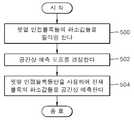
상기의 다른 과제를 이루기 위해, 본 발명에 따른 화상 데이터의 부호화 장치는 현재 블록과 공간상 인접하는 인접 블록들 중 현재 블록의 윗열에 해당하는 윗열 인접 블록들을 사용하여 현재 블록의 화소값들을 공간상 예측하는 공간상 예측부, 공간상 예측된 화소값들을 변환 및 양자화하는 변환 및 양자화부 및 변환 및 양자화된 화소값들에 대한 비트열을 생성하는 비트열 생성부를 구비하고, 공간상 예측부는 화상의 소정 라인들 단위마다 윗열 인접 블록들의 화소값들을 소정 기준값으로 대체하여 공간상 예측하는 것을 특징으로 한다.In order to achieve the above object, the image data encoding apparatus according to the present invention spatially stores pixel values of a current block using upper row adjacent blocks corresponding to the upper row of the current block among adjacent blocks adjacent to the current block. A spatial predictor for predicting, a transform and quantizer for transforming and quantizing the spatially predicted pixel values, and a bit string generator for generating a bit string for the transformed and quantized pixel values, wherein the spatial predictor The spatial prediction is performed by substituting a predetermined reference value for the pixel values of the adjacent blocks in each of the predetermined lines.
상기의 다른 과제를 이루기 위해, 본 발명에 따른 화상 데이터의 공간상 예 측 보상장치는 현재 블록과 공간상 인접하는 인접 블록들 중 현재 블록의 윗열에 해당하는 윗열 인접 블록들을 사용하여 공간상 예측된 화소값들을 보상하는 공간상 예측 보상부를 구비하고, 공간상 예측 보상부는 화상의 소정 라인들 단위마다 공간상 예측된 화소값들을 보상하는 것을 특징으로 한다.In order to achieve the above object, the spatial predictive compensation device of the image data according to the present invention is spatially predicted by using the upper row adjacent blocks corresponding to the upper row of the current block among the adjacent blocks in the space adjacent to the current block. And a spatial prediction compensator for compensating the pixel values, wherein the spatial prediction compensator compensates for the spatially predicted pixel values for every predetermined line unit of the image.
상기의 다른 과제를 이루기 위해, 본 발명에 따른 화상 데이터의 복호화장치는 화상 데이터의 비트열을 복호화하는 비트열 복호화부, 복호화된 화상 데이터를 역양자화 및 역변환하는 역양자화 및 역변환부 및 현재 블록과 공간상 인접하는 인접 블록들 중 현재 블록의 윗열에 해당하는 윗열 인접 블록들만을 사용하여 공간상 예측된 화소값들을 보상하는 공간상 예측 보상부를 구비하고, 공간상 예측 보상부는 화상의 소정 라인들 단위마다 공간상 예측된 화소값들을 보상하는 것을 특징으로 한다.In order to achieve the above object, the image data decoding apparatus according to the present invention includes a bit string decoding unit for decoding a bit string of image data, an inverse quantization and inverse transform unit for inverse quantization and inverse transformation of the decoded image data, and a current block. A spatial prediction compensator for compensating spatially predicted pixel values by using only the upper column adjacent blocks corresponding to the upper row of the current block among the adjacent blocks in the space; Compensating the spatially predicted pixel values for each.
상기의 다른 과제를 이루기 위해, 본 발명에 따른 화상 데이터의 공간상 예측 방법은 현재 블록과 공간상 인접하는 인접 블록들 중 현재 블록의 윗열에 해당하는 윗열 인접 블록들만을 사용하여 현재 블록의 화소값들을 공간상 예측하는 단계를 구비하고, 현재 블록의 화소값들을 공간상 예측할 때에, 화상의 소정 라인들 단위마다 윗열 인접 블록들의 화소값들을 소정 기준값으로 대체하여 공간상 예측하는 것을 특징으로 한다.In order to achieve the above object, the spatial prediction method of the image data according to the present invention uses only the upper column adjacent blocks corresponding to the upper column of the current block among the adjacent blocks in the space adjacent to the current block, and thus the pixel value of the current block. And spatially predicting the pixel values of the current block, and spatially predicting the pixel values of the adjacent blocks of the upper row for each predetermined line unit of the image by a predetermined reference value.
상기의 다른 과제를 이루기 위해, 본 발명에 따른 화상 데이터의 부호화 방법은 현재 블록과 공간상 인접하는 인접 블록들 중 현재 블록의 윗열에 해당하는 윗열 인접 블록들만을 사용하여 현재 블록의 화소값들을 공간상 예측하는 단계, 공 간상 예측된 화소값들을 변환 및 양자화하는 단계 및 변환 및 양자화된 화소값들에 대한 비트열을 생성하는 단계를 구비하고, 현재 블록의 화소값들을 공간상 예측할 때에, 화상의 소정 라인들 단위마다 윗열 인접 블록들의 화소값들을 소정 기준값으로 대체하여 공간상 예측하는 것을 특징으로 한다.In order to achieve the above object, the encoding method of the image data according to the present invention uses only the upper column adjacent blocks corresponding to the upper column of the current block among the adjacent blocks in space to store the pixel values of the current block. Image predicting, transforming and quantizing spatially predicted pixel values, and generating a bit string for the transformed and quantized pixel values, wherein when spatially predicting pixel values of a current block, The spatial prediction is performed by substituting a predetermined reference value for the pixel values of the adjacent blocks in each of the predetermined lines.
상기의 다른 과제를 이루기 위해, 본 발명에 따른 화상 데이터의 공간상 예측 보상방법은 현재 블록과 공간상 인접하는 인접 블록들 중 현재 블록의 윗열에 해당하는 윗열 인접 블록들만을 사용하여 공간상 예측된 화소값들을 보상하는 단계를 구비하고, 공간상 예측된 화소값들을 보상하는 단계는 화상의 소정 라인들 단위마다 공간상 예측된 화소값들을 보상하는 것을 특징으로 한다.In order to achieve the above object, the spatial prediction compensation method of the image data according to the present invention is spatially predicted using only the upper column adjacent blocks corresponding to the upper row of the current block among the adjacent blocks in the space adjacent to the current block. Compensating the pixel values, and compensating the spatially predicted pixel values is characterized by compensating the spatially predicted pixel values for each predetermined line unit of the image.
상기의 다른 과제를 이루기 위해, 본 발명에 따른 화상 데이터의 복호화방법은 화상 데이터의 비트열을 복호화하는 단계, 복호화된 화상 데이터를 역양자화 및 역변환하는 단계 및 현재 블록과 공간상 인접하는 인접 블록들 중 현재 블록의 윗열에 해당하는 윗열 인접 블록들만을 사용하여 공간상 예측된 화소값들을 보상하는 단계를 구비하고, 공간상 예측된 화소값들을 보상하는 단계는 화상의 소정 라인들 단위마다 공간상 예측된 화소값들을 보상하는 것을 특징으로 한다.According to another aspect of the present invention, there is provided a method of decoding image data, the method comprising: decoding a bit stream of image data, inverse quantizing and inversely transforming the decoded image data, and adjacent blocks adjacent in space with the current block. Compensating the spatially predicted pixel values using only the upper column adjacent blocks corresponding to the upper column of the current block, and compensating the spatially predicted pixel values by spatially predicting each unit of predetermined lines of the image. The pixel values are compensated for.
이하, 본 발명에 의한 화상 데이터의 공간상 예측장치를 첨부된 도면을 참조하여 다음과 같이 설명한다.Hereinafter, a spatial prediction apparatus of image data according to the present invention will be described with reference to the accompanying drawings.
도 3은 본 발명에 의한 화상 데이터의 공간상 예측장치를 설명하기 위한 일 실시예의 블록도로서, 화소값 필터링부(100), 예측 모드 결정부(120) 및 공간상 예측부(140)로 구성된다.3 is a block diagram of an exemplary embodiment for describing a spatial prediction apparatus of image data according to the present invention, and includes a pixel
화소값 필터링부(100)는 현재 블록의 공간상 예측에 사용되는 윗열 인접 블록들의 화소값들을 필터링하고, 필터링한 결과를 예측 모드 결정부(120)로 출력한다. 윗열 인접 블록들의 화소값들을 필터링하는 이유는 윗열 인접 블록들의 화소값들만을 이용하여 공간상 예측함으로 인해 나타나는 화질의 열화를 방지하기 위함이다.The pixel
특히, 화소값 필터링부(100)는 윗열 인접 블록들의 화소값들 중 임의의 화소값에 대한 주변 화소값들의 평균값을 임의의 화소값에 대한 필터링값으로서 검출한다.In particular, the pixel
도 4는 4*4 블록의 화소값들 및 블록 주변의 화소값들의 일 예를 나타내는 도면이다. 도 4를 참조하여 필터링 과정을 설명한다. 예를 들어, 화소값 필터링부(100)는 윗열 인접 블록들의 화소값들 중 예측에 사용되는 화소값 A의 좌우에 인접하는 화소값들의 평균값을 화소값 A에 대한 필터링값으로 검출한다. 즉, 공간상 예측에 사용되는 값으로 A 대신에 (P+B)/2, (P+2A+B)/4, (2O+3P+6A+3B+2C)/16 등의 값들 중 어느 하나를 사용한다. 이와 같은 방법으로 공간상 예측에 사용되는 값으로 B 대신에 (A+C)/2, (A+2B+C)/4, (2P+3A+6B+3C+2D)/16 등의 값들 중 어느 하나를 사용한다. 나머지 인접 블록들의 화소값들도 전술한 방식으로 필터링한다. 이렇게 필터링하는 방법은 일 예에 지나지 않으며, 보다 많은 인접블록들의 화소값들을 이용하여 필터링할 수도 있다.4 is a diagram illustrating an example of pixel values of a 4 * 4 block and pixel values around the block. A filtering process will be described with reference to FIG. 4. For example, the pixel
예측 모드 결정부(120)는 윗열 인접 블록들의 화소값들 및 화소값 필터링부(100)에서 필터링된 화소값들을 사용하여, 현재 블록의 공간상 예측 모드를 결정 하고, 결정된 결과를 공간상 예측부(140)로 출력한다.The
예측 모드 결정부(120)는 윗열 인접 블록들의 화소값들과 현재 블록의 화소값들 사이의 차이값들의 합 및 윗열 인접 블록들의 필터링된 화소값들과 현재 블록의 화소값들 사이의 차이값들의 합이 공간상 예측 방향에 따라 최소값을 갖는 것을 공간상 예측 모드로 결정하는 것을 특징으로 한다. 여기서, 공간상 예측 방향은 수직 방향, 우측 사선 방향 및 좌측 사선 방향 중 어느 한 방향인 것을 특징으로 한다.The
도 5는 1차원 블록에 해당하는 8*1 블록에 대한 예측 방향의 일 예를 나타내는 도면이다. 1차원 블록은 블록의 가로열이 1열에 해당하는 것을 의미한다. 도 5a는 8*1 블록에 대한 예측 방향이 수직 방향인 것을 나타내는 도면이고, 도 5b는 8*1 블록에 대한 예측 방향이 우측 사선 방향인 것을 나타내는 도면이고, 도 5c는 8*1 블록에 대한 예측 방향이 좌측 사선 방향인 것을 나타내는 도면이다. 1차원 블록에 대한 도 5에 도시된 공간상 예측 방향은 일 예에 지나지 않는 것으로, 도시된 방향 이외에 보다 다양한 공간상 예측방향이 제시될 수 있다.5 is a diagram illustrating an example of a prediction direction for an 8 * 1 block corresponding to a 1-dimensional block. One-dimensional block means that the row of blocks corresponds to one column. FIG. 5A is a diagram illustrating that the prediction direction for an 8 * 1 block is a vertical direction, FIG. 5B is a diagram illustrating the prediction direction for an 8 * 1 block, and a right diagonal direction, and FIG. 5C is a diagram for an 8 * 1 block. It is a figure which shows that a prediction direction is a left diagonal direction. The spatial prediction direction shown in FIG. 5 with respect to the one-dimensional block is merely an example, and various spatial prediction directions may be presented in addition to the illustrated direction.
도 6은 2차원 블록에 해당하는 4*4 블록에 대한 예측 방향의 일 예를 나타내는 도면이다. 2차원 블록은 블록의 가로열이 적어도 2열 이상인 것을 의미한다.도 6a는 4*4 블록에 대한 예측 방향이 우측 사선 방향인 것을 나타내는 도면이고, 도 6b는 4*4 블록에 대한 예측 방향이 수직 방향인 것을 나타내는 도면이고, 도 6c는 4*4 블록에 대한 예측 방향이 좌측 사선 방향인 것을 나타내는 도면이다. 2차원 블록에 대한 도 6에 도시된 공간상 예측 방향은 일 예에 지나지 않는 것으로, 도시된 방향 이외에 보다 다양한 공간상 예측방향이 제시될 수 있다.6 is a diagram illustrating an example of a prediction direction for a 4 * 4 block corresponding to a 2D block. The two-dimensional block means that the horizontal columns of the blocks are at least two columns or more. FIG. 6A is a diagram showing that the prediction direction for a 4 * 4 block is a right diagonal direction, and FIG. 6B is a prediction direction for a 4 * 4 block. It is a figure which shows that it is a vertical direction, and FIG. 6C is a figure which shows that the prediction direction with respect to a 4 * 4 block is a left diagonal direction. The spatial prediction direction shown in FIG. 6 for the 2D block is only an example, and various spatial prediction directions may be presented in addition to the illustrated direction.
공간상 예측 모드는 상기 수직 방향에 대해 윗열 인접 블록들의 필터링된 화소값들을 사용하여 예측하기 위한 제1 예측 모드, 수직 방향에 대해 필터링되지 않은 원래의 화소값들을 사용하여 예측하기 위한 제2 예측 모드, 우측 사선 방향에 대해 윗열 인접 블록들의 필터링된 화소값들을 사용하여 예측하기 위한 제3 예측 모드 및 좌측 사선 방향에 대해 윗열 인접 블록들의 필터링된 화소값들을 사용하여 예측하기 위한 제4 예측 모드를 포함하는 것을 특징으로 한다. 공간상 예측 모드는 전술한 모드 이외에, 우측 사선 방향에 대해 필터링되지 않은 원래의 화소값들을 사용하여 예측하기 위한 제5 예측 모드 및 우측 사선 방향에 대해 필터링되지 않은 원래의 화소값들을 사용하여 예측하기 위한 제6 예측 모드를 더 포함할 수도 있다. 또한, 공간상 예측 방향이 수직 방향, 우측 사선 방향 및 좌측 사선 방향 이외에 더 세분될 경우에는 공간상 예측 모드는 더욱 늘어날 수 있다.The spatial prediction mode is a first prediction mode for predicting using the filtered pixel values of the upper column adjacent blocks with respect to the vertical direction, and a second prediction mode for predicting using the original unfiltered pixel values with respect to the vertical direction. A third prediction mode for predicting using the filtered pixel values of the upper row adjacent blocks for the right diagonal direction and a fourth prediction mode for predicting using the filtered pixel values of the upper row adjacent blocks for the left diagonal direction. Characterized in that. The spatial prediction mode is predicted using the fifth prediction mode for predicting using the original unfiltered pixel values for the right oblique direction and the original unfiltered pixel values for the right oblique direction in addition to the above-described mode. It may further include a sixth prediction mode. In addition, when the spatial prediction direction is further subdivided other than the vertical direction, the right diagonal direction and the left diagonal direction, the spatial prediction mode may be further increased.
도 4 및 도 5를 사용해 공간상의 예측 모드를 결정하는 방식을 설명한다. 이때, 예측 모드는 전술한 제1 예측 모드 내지 제4 예측 모드라고 가정한다. 예측 모드 결정부(120)는 공간상 예측 방향 중 수직 방향에 해당하는 현재 블록의 화소값들과 윗열 인접블록의 화소값들의 차이값들을 구한다. 구해진 차이값들은 각각 a1=a-A, b1=b-B, c1=c-C, d1=d-D, e1=e-A, f1=f-B, g1=g-C, h1=h-D, i1=i-A, j1=j-B, k1=k-C, l1=l-D, m1=m-A, n1=n-B, o1=o-C, p1=p-D가 된다. 이러한 수직 방향의 R, G 및 B 각각에 대한 차이값들의 절대값의 합을 각각 S11, S12및 S13이라 가정한다.A method of determining a prediction mode in space will be described with reference to FIGS. 4 and 5. In this case, it is assumed that the prediction mode is the first to fourth prediction modes described above. The
한편, 윗열 인접 블록의 필터링된 값들을 각각 A', B', C', D', E', F', G', H', M', N', O' 및 P'라 하면, 예측 모드 결정부(120)는 공간상 예측 방향 중 수직 방향에 해당하는 현재 블록의 화소값들과 윗열 인접블록의 필터링된 화소값들의 차이값들을 구한다. 구해진 차이값들은 각각 a2=a-A', b2=b-B', c2=c-C', d2=d-D', e2=e-A', f2=f-B', g2=g-C', h2=h-D', i2=i-A', j2=j-B', k2=k-C', l2=l-D', m2=m-A', n2=n-B', o2=o-C', p2=p-D'가 된다. 이러한 수직 방향의 R, G 및 B 각각에 대한 차이값들의 절대값의 합을 각각 S21, S22및 S23이라 가정한다.On the other hand, if the filtered values of the adjacent blocks in the upper column are A ', B', C ', D', E ', F', G ', H', M ', N', O 'and P', The
또한, 예측 모드 결정부(120)는 공간상 예측 방향 중 우측 사선 방향에 해당하는 현재 블록의 화소값들과 윗열 인접블록의 필터링된 화소값들 사이의 차이값들을 구한다. 구해진 차이값들은 각각 a3=a-P', b3=b-A', c3=c-B', d3=d-C', e3=e-O', f3=f-P', g3=g-A', h3=h-B', i3=i-N', j3=j-O', k3=k-P', l3=l-A', m3=m-M', n3=n-N', o3=o-O', p3=p-P'가 된다. 이러한 우측 사선 방향의 R, G 및 B 각각에 대한 차이값들의 절대값의 합을 각각 S4, S5및 S6라 가정한다.In addition, the
또한, 예측 모드 결정부(120)는 공간상 예측 방향 중 좌측 사선 방향에 해당하는 현재 블록의 화소값들과 윗열 인접블록의 필터링된 화소값들 사이의 차이값들을 구한다. 구해진 차이값들은 각각 a4=a-B', b4=b-C', c4=c-D', d4=d-E', e4=e-C', f4=f-D', g4=g-E', h4=h-F', i4=i-D', j4=j-E', k4=k-F', l4=l-G', m4=m-E', n4=n-F', o4=o-G', p4=p-H'가 된다. 이러한 우측 사선 방향의 R, G 및 B 각각에 대한 차이값들의 절대값의 합을 각각 S7, S8및 S9이라 가정한다.In addition, the
예측 모드 결정부(120)는 구해진 차이값들의 합들 S11, S12, S13, S21, S22, S23, S4, S5, S6, S7, S8및 S9중 R, G 및 B 각각에 대해 차이값들에 대한 크기가 초소값을 갖는 것을 R, G 및 B 각각에 대한 공간상의 예측 모드로 결정한다.The
이때, 예측 모드는 R, G, B 각각에 대해 독립적으로 결정될 수 있고, 또는 R, G, B에 대해 공통으로 결정될 수도 있다. 예측 모드가 R, G, B 각각에 대해 독립적으로 결정된다는 것은 S11, S21, S4및 S7 중 가장 작은 값을 갖는 것이 R 성분의 예측 모드로 결정되고, 마찬가지로 S12, S22, S5 및 S8 중 가장 작은 값을 갖는 것이예측 방향이 G 성분의 예측 방향으로 결정되고, S13, S23, S6 및 S9 중 가장 작은 값을 갖는 것이 B 성분의 예측 모드로 결정되는 것을 의미한다.In this case, the prediction mode may be independently determined for each of R, G, and B, or may be determined in common for R, G, and B. The prediction mode is determined independently for each of R, G, and B is S11 , S21 , S4 And the one having the smallest value among S7 is determined as the prediction mode of the R component, and similarly the one having the smallest value among S12 , S22 , S5 and S8 is determined as the prediction direction of the G component, The one having the smallest value among S13 , S23 , S6, and S9 means that the prediction mode of the B component is determined.
예측 모드가 R, G, B에 대해 공통으로 결정된다는 것은 SV1=S11+S12+S13, SV2=S21+S22+S23, SR=S4+S5+S6및 SL=S7+S8+S9 중 가장 작은 값을 갖는 것을 공간상의 예측 모드로 결정되는 것을 의미한다.The prediction mode is determined in common for R, G, and B: SV1 = S11 + S12 + S13 , SV2 = S21 + S22 + S23 , SR = S4 + S5 + S6 And SL = S7 + S8 + S9, which means the smallest value is determined as the spatial prediction mode.
한편, R, G 및 B의 합을 구할 때, 각각에 대해 가중치를 달리하여 합산할 수 있다. 예를 들어, S11, S12및 S13의 가중치를 달리하여 합을 구할 수도 있다. 즉,SV1=0.3*S11+0.6*S12+0.1*S13로 표현될 수 있다. 이렇게 합산되는 S11, S12및 S13의 가 중치를 달리하는 이유는 화상에 있어서 G에 대한 처리가 중요하기 때문이다. 전술한 가중치는 예시적인 것으로 다양한 가중치가 적용될 수 있다.On the other hand, when calculating the sum of R, G, and B, the weights can be summed for each of them. For example, S11 , S12 And the sum may be obtained by varying the weight of S13 . In other words, It can be expressed as SV1 = 0.3 * S11 + 0.6 * S12 + 0.1 * S13 . So summed up S11 , S12 The reason why the weights of and S13 differ is that the processing for G is important in the image. The above-described weights are exemplary and various weights may be applied.
공간상 예측부(140)는 화상의 현재 블록과 공간상 인접하는 인접 블록들 중 현재 블록의 윗열에 해당하는 윗열 인접 블록들을 사용하여 현재 블록의 화소값들을 공간상 예측한다. 종래와 달리 본원 발명의 공간상 예측부(140)는 공간상 예측을 위한 인접블록들의 화소값들로서 윗열 인접블록들의 화소값들만을 사용한다. 공간상 예측방향은 전술한 바와 같이, 수직방향, 우측 사선방향 및 좌측 사선 방향 등이 있을 수 있다.The
공간상 예측부(140)는 1차원 블록에 대한 화소값들을 공간상 예측할 수도 있고, 2차원 블록에 대한 화소값들을 공간상 예측할 수도 있다. 도 5는 1차원 블록에 대한 예측 방향의 일 예를 나타내고 있으며, 도 6은 2차원 블록에 대한 예측 방향의 일 예를 나타내고 있다.The
도 7은 에지 부분이 존재하는 화상의 1차원 블록에 대해 수직 방향으로 공간상 예측을 수행한 일 예를 나타낸 도면이다.FIG. 7 is a diagram illustrating an example of performing spatial prediction in a vertical direction with respect to a 1-dimensional block of an image in which an edge part exists.
도 7의 (a)는 현재 블록의 윗열 인접블록들의 화소값들 "0, 0, 100 및 100"이 화소값 필터링부(100)에 의해 필터링되어 "13, 31, 69 및 88"의 필터링값들로 대체된 것을 나타내는 도면이다. 이렇게 필터링된 값들과 현재 블록의 화소값들의 차로부터 공간상 예측된 값 "13, 31, -31 및 -12"을 구할 수 있다.FIG. 7A illustrates pixel values “0, 0, 100, and 100” of upper row adjacent blocks of the current block by the pixel
도 7의 (b)는 현재 블록의 윗열 인접블록들의 화소값들 "0, 0, 100 및 100"과 현재 블록의 화소값들의 차로부터 공간상 예측된 값 "0, 0, 0 및 0"을 구한 예 를 나타낸 도면이다. 에지 부분이 나타나는 화상에서 윗열 인접 블록에 대한 화소값들을 필터링하여 공간상 예측할 경우에는, 윗열 인접 블록들의 원래의 화소값들을 사용해 공간상 예측하는 경우보다 부호화 효율이 상대적으로 낮아짐을 확인할 수 있다. 전술한 예측 모드 결정부(120)는 부호화 효율이 상대적으로 높은 예측 모드를 결정한다. 즉, 예측 모드 결정부(120)는 수직 방향에 대해 필터링되지 않은 원래의 화소값들을 사용하여 예측하도록 하는 모드 즉, 제2 예측 모드로 결정한다. 그러면, 공간상 예측부(140)는 결정된 제2 예측 모드에 따라, 수직 방향에 대해 필터링되지 않은 원래의 화소값들과 현재 블록의 화소값들의 차로부터 공간상 예측된 값을 검출한다.7B illustrates spatially predicted values “0, 0, 0 and 0” from the difference between pixel values “0, 0, 100 and 100” of the upper row adjacent blocks of the current block and pixel values of the current block. It is a figure which shows the obtained example. When spatial prediction is performed by filtering the pixel values of the adjacent blocks in the upper row in the image where the edge part appears, it can be seen that the coding efficiency is relatively lower than when spatial prediction is performed using the original pixel values of the adjacent blocks in the upper columns. The aforementioned
공간상 예측부(140)는 화상의 소정 라인들 단위마다 윗열 인접 블록들의 화소값들을 소정 기준값으로 대체하여 공간상 예측하는 것을 특징으로 한다.The
도 8은 소정 라인들 단위마다 윗열 인접 블록들의 화소값들을 소정 기준값으로 대체하여 공간상 예측하는 일 예를 나타내는 도면이다.8 is a diagram illustrating an example of spatial prediction by replacing pixel values of upper row adjacent blocks with predetermined reference values for every predetermined line unit.
도 8의 (a)는 종래의 공간상 예측을 수행하는 방식을 도시한 것으로 화상 전체에 대해 윗열 인접 블록들의 화소값들을 기초로 하여 공간상 예측하는 방식을 도시한 것이다.FIG. 8A illustrates a conventional method of performing spatial prediction, and illustrates a method of performing spatial prediction based on pixel values of upper row adjacent blocks for an entire image.
도 8의 (b)는 화상에 대해 N개의 라인들 별로 그룹핑하고, 제1 그룹에 대해 공간상 예측이 완료되면, 제2 그룹의 첫번째 열에 대한 공간상 예측을 할 때에, 제1 그룹의 마지막 열을 기초로하여 공간상 예측을 수행하는 것이 아니라, 미리 정해진 기준값을 윗열 인접 블록들의 화소값으로 간주하여 제2 그룹의 첫번째 열에 대 한 공간상 예측을 수행한다. 마찬가지로, 제2 그룹에 대해 공간상 예측이 완료되면, 제3 그룹의 첫번째 열에 대한 공간상 예측을 할 때에, 제2 그룹의 마지막 열을 기초로 하여 공간상 예측을 수행하는 것이 아니라, 미리 정해진 기준값을 윗열 인접 블록들의 화소값으로 간주하여 제3 그룹의 첫번째 열에 대한 공간상 예측을 수행한다.FIG. 8 (b) shows the last column of the first group when performing spatial prediction on the first column of the second group when grouping by N lines for the image and spatial prediction on the first group is completed. Rather than performing spatial prediction based on the above, the spatial prediction is performed on the first column of the second group by considering the predetermined reference value as the pixel value of the adjacent blocks. Similarly, if the spatial prediction is completed for the second group, when performing the spatial prediction for the first column of the third group, instead of performing the spatial prediction based on the last column of the second group, the predetermined reference value S is regarded as a pixel value of upper row adjacent blocks, and spatial prediction is performed on the first column of the third group.
소정 기준값은 화상의 계조값들 중 중간 계조값을 기준값으로 설정하는 것을 특징으로 한다. 예를 들어, 화상의 계조값들이 0 내지 255의 계조값들로 구분되어 있다면, 0 내지 255의 계조값들 중 중간 계조값에 해당하는 128을 소정 기준값으로 설정한다. 그룹핑된 열들 각각의 첫번째 열과 소정 기준값 예를 들어 128의 차가 공간상 예측에 의한 값으로서 검출된다.The predetermined reference value is characterized by setting the intermediate gradation value among the gradation values of the image as the reference value. For example, if the grayscale values of the image are divided into grayscale values of 0 to 255, 128 corresponding to the intermediate grayscale value among the grayscale values of 0 to 255 is set as a predetermined reference value. The difference between the first column of each of the grouped columns and a predetermined reference value, for example 128, is detected as the value by spatial prediction.
도 8의 (b)에 도시된 바와 같이, 소정 라인들 단위마다 윗열 인접 블록들의 화소값들을 소정 기준값으로 대체하여 공간상 예측을 함으로써, 에지 부분이 존재하는 화상에 대해 공간상 예측을 할 때에 발생하는 에러의 확산을 차단할 수 있는 효과가 있다.As shown in (b) of FIG. 8, the spatial prediction is performed by replacing the pixel values of the upper row adjacent blocks for each predetermined line unit with a predetermined reference value, thereby generating spatial prediction for an image having an edge portion. There is an effect that can block the spread of the error.
도 9는 3 라인들마다 윗열 인접 블록들의 화소값들을 소정 기준값으로 대체하여 공간상 예측하는 일 예를 나타내는 도면이다. 도 9의 (a)는 종래의 공간상 예측을 수행하는 방식을 도시한 것이고, 도 9의 (b)는 화상에 대해 3개의 라인들 별로 그룹핑한 것으로, 제j 그룹에 대해 공간상 예측이 완료되면, 제k 그룹의 첫번째 열에 대한 공간상 예측을 할 때에, 제j 그룹의 마지막 열을 기초로하여 공간상 예측을 수행하는 것이 아니라, 미리 정해진 기준값 예를 들어, 128을 제k 그룹의 첫 번째 열에 대한 윗열 인접 블록들의 화소값들으로 간주하여 제k 그룹의 첫번째 열의 화소값들과 차감함으로써, 공간상 예측에 대한 값을 검출한다.9 is a diagram illustrating an example of spatial prediction by replacing pixel values of upper row adjacent blocks with predetermined reference values every three lines. FIG. 9A illustrates a conventional spatial prediction method, and FIG. 9B is a grouping of three lines for an image, and the spatial prediction is completed for the j-th group. When performing the spatial prediction on the first column of the k-th group, instead of performing the spatial prediction based on the last column of the j-th group, the predetermined reference value, for example, 128 is set to the first of the k-th group. A value for spatial prediction is detected by subtracting the pixel values of the first column of the kth group by considering the pixel values of the upper column adjacent blocks for the column.
도 10은 화상의 에지 부분(예를 들어, 커서(cursor))에 의해 부호화시에 발생하는 에러의 확산을 차단하는 것을 예시하는 도면이다. 도 10의 (a)는 커서가 존재하는 위치에서 발생하는 에러가 커서 이하의 화상에 대한 부호화시에 에러 확산이 이루어지는 것을 나타내는 도면이고, 도 10의 (b)는 소정 라인들마다 공간상 예측을 위한 윗열 인접 블록들의 화소값들을 소정 기준값으로 대체하여 예측함으로써, 에러 확산을 커서가 존재하는 제2 그룹에 한정하도록 할 수 있다. 따라서, 화상의 에지 부분에 대한 공간상 예측시 에러 확산을 차단함으로써, 화질의 열화를 방지할 수 있다.FIG. 10 is a diagram illustrating blocking of spreading of an error occurring at the time of encoding by an edge portion (for example, a cursor) of an image. FIG. 10A is a diagram illustrating that error spreading occurs when encoding an image below a cursor when an error occurring at a location where a cursor is present, and FIG. 10B illustrates spatial prediction for each predetermined line. By predicting by substituting the pixel values of the upper neighboring blocks for a predetermined reference value, the error diffusion may be limited to the second group in which the cursor exists. Therefore, by preventing error diffusion in spatial prediction of the edge portion of the image, deterioration of image quality can be prevented.
이하, 본 발명에 의한 화상 데이터의 부호화 장치를 첨부된 도면을 참조하여 다음과 같이 설명한다.EMBODIMENT OF THE INVENTION Hereinafter, the image data encoding apparatus by this invention is demonstrated as follows with reference to attached drawing.
도 11은 본 발명에 의한 화상 데이터의 부호화 장치를 설명하기 위한 일 실시예의 블록도로서, 화소값 필터링부(200), 예측 모드 결정부(210), 공간상 예측부(220), 변환 및 양자화부(230) 및 비트열 생성부(240)로 구성된다.FIG. 11 is a block diagram illustrating an example of an apparatus for encoding image data according to an embodiment of the present invention. The pixel
화소값 필터링부(200)는 현재 블록의 공간상 예측에 사용되는 윗열 인접 블록들의 화소값들을 필터링하고, 필터링한 결과를 예측 모드 결정부(210)로 출력한다. 화소값 필터링부(200)는 윗열 인접 블록들의 화소값들 중 임의의 화소값에 대한 주변 화소값들의 평균값을 임의의 화소값에 대한 필터링값으로서 검출한다. 화소값 필터링부(200)는 전술한 화소값 필터링부(100)와 기능이 동일하므로, 상세한 설명은 생략한다.The pixel
예측 모드 결정부(210)는 윗열 인접 블록들의 화소값들 및 화소값 필터링부(200)에서 필터링된 화소값들을 사용하여, 현재 블록의 공간상 예측 모드를 결정하고, 결정된 결과를 공간상 예측부(220)로 출력한다.The
예측 모드 결정부(210)는 윗열 인접 블록들의 화소값들과 현재 블록의 화소값들 사이의 차이값들의 합 및 윗열 인접 블록들의 필터링된 화소값들과 현재 블록의 화소값들 사이의 차이값들의 합이 공간상 예측 방향에 따라 최소값을 갖는 것을 공간상 예측 모드로 결정하는 것을 특징으로 한다.The
여기서, 공간상 예측 방향은 수직 방향, 우측 사선 방향 및 좌측 사선 방향 중 어느 한 방향인 것을 특징으로 한다. 공간상 예측 모드는 상기 수직 방향에 대해 윗열 인접 블록들의 필터링된 화소값들을 사용하여 예측하기 위한 제1 예측 모드, 수직 방향에 대해 필터링되지 않은 원래의 화소값들을 사용하여 예측하기 위한 제2 예측 모드, 우측 사선 방향에 대해 윗열 인접 블록들의 필터링된 화소값들을 사용하여 예측하기 위한 제3 예측 모드 및 좌측 사선 방향에 대해 윗열 인접 블록들의 필터링된 화소값들을 사용하여 예측하기 위한 제4 예측 모드를 포함하는 것을 특징으로 한다.In this case, the spatial prediction direction is one of a vertical direction, a right diagonal direction and a left diagonal direction. The spatial prediction mode is a first prediction mode for predicting using the filtered pixel values of the upper column adjacent blocks with respect to the vertical direction, and a second prediction mode for predicting using the original unfiltered pixel values with respect to the vertical direction. A third prediction mode for predicting using the filtered pixel values of the upper row adjacent blocks for the right diagonal direction and a fourth prediction mode for predicting using the filtered pixel values of the upper row adjacent blocks for the left diagonal direction. Characterized in that.
공간상 예측 모드는 전술한 모드 이외에, 우측 사선 방향에 대해 필터링되지 않은 원래의 화소값들을 사용하여 예측하기 위한 제5 예측 모드 및 우측 사선 방향에 대해 필터링되지 않은 원래의 화소값들을 사용하여 예측하기 위한 제6 예측 모드를 더 포함할 수도 있다. 또한, 공간상 예측 방향이 수직 방향, 우측 사선 방향 및 좌측 사선 방향 이외에 더 세분될 경우에는 공간상 예측 모드는 더욱 늘어날 수 있다. 예측 모드 결정부(210)는 전술한 예측 모드 결정부(120)와 기능이 동일하므로, 상세한 설명은 생략한다.The spatial prediction mode is predicted using the fifth prediction mode for predicting using the original unfiltered pixel values for the right oblique direction and the original unfiltered pixel values for the right oblique direction in addition to the above-described mode. It may further include a sixth prediction mode. In addition, when the spatial prediction direction is further subdivided other than the vertical direction, the right diagonal direction and the left diagonal direction, the spatial prediction mode may be further increased. Since the
공간상 예측부(220)는 화상의 현재 블록과 공간상 인접하는 인접 블록들 중 현재 블록의 윗열에 해당하는 윗열 인접 블록들을 사용하여 현재 블록의 화소값들을 공간상 예측한다. 공간상 예측부(220)는 공간상 예측을 위한 인접블록들의 화소값들로서 윗열 인접블록들의 화소값들만을 사용한다. 공간상 예측방향은 전술한 바와 같이, 수직방향, 우측 사선방향 및 좌측 사선 방향 등이 있을 수 있다. 공간상 예측부(220)는 1차원 블록에 대한 화소값들을 공간상 예측할 수도 있고, 2차원 블록에 대한 화소값들을 공간상 예측할 수도 있다. 도 5는 1차원 블록에 대한 예측 방향의 일 예를 나타내고 있으며, 도 6은 2차원 블록에 대한 예측 방향의 일 예를 나타내고 있다.The
공간상 예측부(220)는 화상의 소정 라인들 단위마다 윗열 인접 블록들의 화소값들을 소정 기준값으로 대체하여 공간상 예측하는 것을 특징으로 한다. 소정 기준값은 화상의 계조값들 중 중간 계조값을 기준값으로 설정하는 것을 특징으로 한다. 예를 들어, 화상의 계조값들이 0 내지 255의 계조값들로 구분되어 있다면, 0 내지 255의 계조값들 중 중간 계조값에 해당하는 128을 소정 기준값으로 설정한다. 그룹핑된 열들 각각의 첫번째 열과 소정 기준값 예를 들어 128의 차가 공간상 예측에 의한 값으로서 검출된다. 공간상 예측부(220)는 전술한 공간상 예측부(140)와 기능이 동일하므로, 상세한 설명은 생략한다.The
변환 및 양자화부(230)는 공간상 예측된 화소값들을 변환 및 양자화하고, 변환 및 양자화한 결과를 비트열 생성부(240)로 출력한다. 변환 방식은 직교 변환 부호화 방식이 적용될 수 있다. 직교 변환 부호화 방식 중에서 많이 사용되는 방식은 이산 코사인 변환(DCT: Discrete Cosine Transform)이 있다. 이산 코사인 변환은 고속 푸리에 변환(FFT)과 마찬가지로 시간축의 화상 신호를 주파수축으로 변환하는데, 변환을 위한 계수로서 이산적 코사인 함수를 사용한다. 이산 코사인 변환은 시간축의 화상 신호를 몇 개의 신호 전력이 큰 주파수 영역과 작은 주파수 영역으로 분해하여 변환하는데, 화상 신호의 전력은 저주파수 영역에 집중되어 있기 때문에 적절한 비트 배분으로 양자화하면 전체의 비트 수를 적게 하여 데이터를 압축할 수 있다.The transform and
비트열 생성부(240)는 예측 모드에 따라 변환 및 양자화된 화소값들에 대한 비트열을 생성한다.The
이하, 본 발명에 의한 화상 데이터의 공간상 예측 보상장치를 첨부된 도면을 참조하여 다음과 같이 설명한다.Hereinafter, a spatial prediction compensation device of image data according to the present invention will be described with reference to the accompanying drawings.
도 12는 본 발명에 의한 화상 데이터의 공간상 예측 보상장치를 설명하기 위한 일 실시예의 블록도로서, 공간상 예측 보상부(300)로 구성된다.FIG. 12 is a block diagram of an exemplary embodiment for explaining a spatial prediction compensation apparatus of image data according to the present invention, and includes a spatial
공간상 예측 보상부(300)는 현재 블록과 공간상 인접하는 인접 블록들 중 현재 블록의 윗열에 해당하는 윗열 인접 블록들만을 사용하여 공간상 예측된 화소값들을 보상한다. 전술한 공간상 예측부(140, 210)에서 공간상 예측된 화소값들은 현재 블록들의 인접블록들 중 윗열에 해당하는 윗열 인접블록들의 화소값들만을 이용 하여 예측한 것이다. 이렇게 예측된 화소값들을 복호화 할 때, 공간상 예측 보상부(300)는 공간상 예측부(140, 210)의 역과정에 따라 윗열 인접 블록들만을 사용하여 공간상 예측된 화소값들을 보상한다.The
특히, 공간상 예측 보상부(300)는 화상의 소정 라인들 단위마다 공간상 예측된 화소값들을 보상하는 것을 특징으로 한다. 전술한 공간상 예측부(140, 210)가 화상의 소정 라인들 단위마다 윗열 인접 블록들의 화소값들을 소정 기준값(예를 들어, 화상의 계조값들 중 중간 계조값)으로 대체하여 공간상 예측한 것에 대해, 공간상 예측 보상부(300)는 예측된 화소값들을 보상한다.In particular, the
이하, 본 발명에 의한 화상 데이터의 복호화장치를 첨부된 도면을 참조하여 다음과 같이 설명한다.Hereinafter, an image data decoding apparatus according to the present invention will be described with reference to the accompanying drawings.
도 13은 본 발명에 의한 화상 데이터의 복호화장치를 설명하기 위한 일 실시예의 블록도로서, 비트열 복호화부(400), 역양자화 및 역변환부(420) 및 공간상 예측 보상부(440)로 구성된다.FIG. 13 is a block diagram illustrating an example of an apparatus for decoding image data according to the present invention, and includes a
비트열 복호화부(400)는 화상 데이터의 비트열을 복호화하고, 복호화한 결과를 역양자화 및 역변환부(420)로 출력한다.The
역양자화 및 역변환부(420)는 복호화된 화상 데이터를 역양자화 및 역변환하고, 역양자화 및 역변환 된 결과를 공간상 예측 보상부(440)로 출력한다. 역양자화 및 역변환부(420)는 변환 및 양자화 과정의 역 과정의 수행을 통해 복호화된 비트열에 대해 역양자화 및 역변환한다.The inverse quantization and
공간상 예측 보상부(440)는 현재 블록과 공간상 인접하는 인접 블록들 중 현 재 블록의 윗열에 해당하는 윗열 인접 블록들만을 사용하여 공간상 예측된 화소값들을 보상한다. 전술한 공간상 예측부((140, 210)에서 공간상 예측된 화소값들은 현재 블록들의 인접블록들 중 윗열에 해당하는 윗열 인접블록들의 화소값들만을 이용하여 예측한 것이다. 이렇게 예측된 화소값들을 복호화 할 때, 공간상 예측 보상부(660)는 공간상 예측부((140, 210)의 역과정에 따라 윗열 인접 블록들만을 사용하여 공간상 예측된 화소값들을 보상한다.The
특히, 공간상 예측 보상부(440)는 화상의 소정 라인들 단위마다 공간상 예측된 화소값들을 보상하는 것을 특징으로 한다. 전술한 공간상 예측부(140, 210)가 화상의 소정 라인들 단위마다 윗열 인접 블록들의 화소값들을 소정 기준값(예를 들어, 화상의 계조값들 중 중간 계조값)으로 대체하여 공간상 예측한 것에 대해, 공간상 예측 보상부(440)는 예측된 화소값들을 보상한다.In particular, the
이하, 본 발명에 의한 화상 데이터의 공간상 예측 방법을 첨부된 도면을 참조하여 다음과 같이 설명한다.Hereinafter, a spatial prediction method of image data according to the present invention will be described with reference to the accompanying drawings.
도 14은 본 발명에 의한 화상 데이터의 공간상 예측 방법을 설명하기 위한 일 실시예의 플로차트이다.14 is a flowchart of an embodiment for explaining a spatial prediction method of image data according to the present invention.
먼저, 화상의 현재 블록과 공간상 인접하는 인접 블록들 중 현재 블록의 윗열에 해당하는 윗열 인접 블록들의 화소값들을 필터링한다(제500 단계). 윗열 인접 블록들의 화소값들을 필터링하는 이유는 윗열 인접 블록들의 화소값들만을 이용하여 공간상 예측함으로 인해 나타나는 화질의 열화를 방지하기 위함이다. 특히, 윗열 인접 블록들의 화소값들 중 임의의 화소값에 대한 주변 화소값들의 평균값을 임 의의 화소값에 대한 필터링값으로서 검출한다. 윗열 인접 블록들의 화소값들을 필터링하는 방식에 대한 설명은 전술한 바와 같으므로, 상세한 설명은 생략한다.First, in
제500 단계 후에, 윗열 인접 블록들의 화소값들 및 필터링된 화소값들을 사용하여 현재 블록의 공간상 예측 모드를 결정한다(제502 단계). 윗열 인접 블록들의 화소값들과 현재 블록의 화소값들 사이의 차이값들의 합 및 윗열 인접 블록들의 필터링된 화소값들과 현재 블록의 화소값들 사이의 차이값들의 합이 공간상 예측 방향에 따라 최소값을 갖는 것을 공간상 예측 모드로 결정하는 것을 특징으로 한다.After
여기서, 공간상 예측 방향은 수직 방향, 우측 사선 방향 및 좌측 사선 방향 중 어느 한 방향인 것을 특징으로 한다. 공간상 예측 모드는 상기 수직 방향에 대해 윗열 인접 블록들의 필터링된 화소값들을 사용하여 예측하기 위한 제1 예측 모드, 수직 방향에 대해 필터링되지 않은 원래의 화소값들을 사용하여 예측하기 위한 제2 예측 모드, 우측 사선 방향에 대해 윗열 인접 블록들의 필터링된 화소값들을 사용하여 예측하기 위한 제3 예측 모드 및 좌측 사선 방향에 대해 윗열 인접 블록들의 필터링된 화소값들을 사용하여 예측하기 위한 제4 예측 모드를 포함하는 것을 특징으로 한다.In this case, the spatial prediction direction is one of a vertical direction, a right diagonal direction and a left diagonal direction. The spatial prediction mode is a first prediction mode for predicting using the filtered pixel values of the upper column adjacent blocks with respect to the vertical direction, and a second prediction mode for predicting using the original unfiltered pixel values with respect to the vertical direction. A third prediction mode for predicting using the filtered pixel values of the upper row adjacent blocks for the right diagonal direction and a fourth prediction mode for predicting using the filtered pixel values of the upper row adjacent blocks for the left diagonal direction. Characterized in that.
공간상 예측 모드는 전술한 모드 이외에, 우측 사선 방향에 대해 필터링되지 않은 원래의 화소값들을 사용하여 예측하기 위한 제5 예측 모드 및 우측 사선 방향에 대해 필터링되지 않은 원래의 화소값들을 사용하여 예측하기 위한 제6 예측 모드를 더 포함할 수도 있다. 또한, 공간상 예측 방향이 수직 방향, 우측 사선 방향 및 좌측 사선 방향 이외에 더 세분될 경우에는 공간상 예측 모드는 더욱 늘어날 수 있다. 공간상의 예측 모드를 결정하는 방식에 대한 설명은 전술한 바와 같으므로, 상세한 설명을 생략한다.The spatial prediction mode is predicted using the fifth prediction mode for predicting using the original unfiltered pixel values for the right oblique direction and the original unfiltered pixel values for the right oblique direction in addition to the above-described mode. It may further include a sixth prediction mode. In addition, when the spatial prediction direction is further subdivided other than the vertical direction, the right diagonal direction and the left diagonal direction, the spatial prediction mode may be further increased. Since the description of the method of determining the spatial prediction mode is as described above, a detailed description thereof will be omitted.
제502 단계 후에, 공간상 예측 모드에 대응하여, 현재 블록의 윗열에 해당하는 윗열 인접 블록들을 사용하여 현재 블록의 화소값들을 공간상 예측한다(제504 단계). 공간상 예측방향은 전술한 바와 같이, 수직방향, 우측 사선방향 및 좌측 사선 방향 등이 있을 수 있다. 1차원 블록에 대한 화소값들을 공간상 예측할 수도 있고, 2차원 블록에 대한 화소값들을 공간상 예측할 수도 있다. 도 5는 1차원 블록에 대한 예측 방향의 일 예를 나타내고 있으며, 도 6은 2차원 블록에 대한 예측 방향의 일 예를 나타내고 있다.After
특히, 화상의 소정 라인들 단위마다 윗열 인접 블록들의 화소값들을 소정 기준값으로 대체하여 공간상 예측하는 것을 특징으로 한다. 소정 기준값은 화상의 계조값들 중 중간 계조값을 기준값으로 설정하는 것을 특징으로 한다. 예를 들어, 화상의 계조값들이 0 내지 255의 계조값들로 구분되어 있다면, 0 내지 255의 계조값들 중 중간 계조값에 해당하는 128을 소정 기준값으로 설정한다. 그룹핑된 열들 각각의 첫번째 열과 소정 기준값 예를 들어 128의 차가 공간상 예측에 의한 값으로서 검출된다. 현재 블록의 윗열에 해당하는 윗열 인접 블록들만을 사용하여 현재 블록의 화소값들을 공간상 예측하는 방식에 대한 설명은 전술한 바와 같으므로, 상세한 설명은 생략한다.In particular, the pixel values of the adjacent blocks in the upper row of the image may be predicted spatially by replacing the pixel values of the adjacent blocks with a predetermined reference value. The predetermined reference value is characterized by setting the intermediate gradation value among the gradation values of the image as the reference value. For example, if the grayscale values of the image are divided into grayscale values of 0 to 255, 128 corresponding to the intermediate grayscale value among the grayscale values of 0 to 255 is set as a predetermined reference value. The difference between the first column of each of the grouped columns and a predetermined reference value, for example 128, is detected as the value by spatial prediction. Since a description of a method of spatially predicting pixel values of the current block using only upper row adjacent blocks corresponding to the upper row of the current block is as described above, a detailed description thereof will be omitted.
이하, 본 발명에 의한 화상 데이터의 부호화 방법을 첨부된 도면을 참조하여 다음과 같이 설명한다.Hereinafter, a method of encoding image data according to the present invention will be described with reference to the accompanying drawings.
도 15는 본 발명에 의한 화상 데이터의 부호화 방법을 설명하기 위한 일 실시예의 플로차트이다.15 is a flowchart of an embodiment for explaining a method of encoding image data according to the present invention.
먼저, 화상의 현재 블록과 공간상 인접하는 인접 블록들 중 현재 블록의 윗열에 해당하는 윗열 인접 블록들의 화소값들을 필터링한다(제600 단계). 윗열 인접 블록들의 화소값들을 필터링하는 이유는 윗열 인접 블록들의 화소값들만을 이용하여 공간상 예측함으로 인해 나타나는 화질의 열화를 방지하기 위함이다. 특히, 윗열 인접 블록들의 화소값들 중 임의의 화소값에 대한 주변 화소값들의 평균값을 임의의 화소값에 대한 필터링값으로서 검출한다. 윗열 인접 블록들의 화소값들을 필터링하는 방식에 대한 설명은 전술한 바와 같으므로, 상세한 설명은 생략한다.First, pixel values of the upper column adjacent blocks corresponding to the upper column of the current block among the adjacent blocks in the space adjacent to the current block of the image are filtered (step 600). The reason for filtering the pixel values of the upper column adjacent blocks is to prevent deterioration of the image quality caused by spatial prediction using only the pixel values of the upper column adjacent blocks. In particular, the average value of the neighboring pixel values for any pixel value of the upper column adjacent blocks is detected as the filtering value for the arbitrary pixel value. Since the description of the method of filtering the pixel values of the upper column adjacent blocks is as described above, a detailed description thereof will be omitted.
제600 단계 후에, 윗열 인접 블록들의 화소값들 및 필터링된 화소값들을 사용하여 현재 블록의 공간상 예측 모드를 결정한다(제602 단계). 윗열 인접 블록들의 화소값들과 현재 블록의 화소값들 사이의 차이값들의 합 및 윗열 인접 블록들의 필터링된 화소값들과 현재 블록의 화소값들 사이의 차이값들의 합이 공간상 예측 방향에 따라 최소값을 갖는 것을 공간상 예측 모드로 결정하는 것을 특징으로 한다. 여기서, 공간상 예측 방향은 수직 방향, 우측 사선 방향 및 좌측 사선 방향 중 어느 한 방향인 것을 특징으로 한다. 공간상 예측 모드는 상기 수직 방향에 대해 윗열 인접 블록들의 필터링된 화소값들을 사용하여 예측하기 위한 제1 예측 모드, 수직 방향에 대해 필터링되지 않은 원래의 화소값들을 사용하여 예측하기 위한 제2 예측 모드, 우측 사선 방향에 대해 윗열 인접 블록들의 필터링된 화소값들을 사용 하여 예측하기 위한 제3 예측 모드 및 좌측 사선 방향에 대해 윗열 인접 블록들의 필터링된 화소값들을 사용하여 예측하기 위한 제4 예측 모드를 포함하는 것을 특징으로 한다.After
공간상 예측 모드는 전술한 모드 이외에, 우측 사선 방향에 대해 필터링되지 않은 원래의 화소값들을 사용하여 예측하기 위한 제5 예측 모드 및 우측 사선 방향에 대해 필터링되지 않은 원래의 화소값들을 사용하여 예측하기 위한 제6 예측 모드를 더 포함할 수도 있다. 또한, 공간상 예측 방향이 수직 방향, 우측 사선 방향 및 좌측 사선 방향 이외에 더 세분될 경우에는 공간상 예측 모드는 더욱 늘어날 수 있다. 공간상의 예측 모드를 결정하는 방식에 대한 설명은 전술한 바와 같으므로, 상세한 설명을 생략한다.The spatial prediction mode is predicted using the fifth prediction mode for predicting using the original unfiltered pixel values for the right oblique direction and the original unfiltered pixel values for the right oblique direction in addition to the above-described mode. It may further include a sixth prediction mode. In addition, when the spatial prediction direction is further subdivided other than the vertical direction, the right diagonal direction and the left diagonal direction, the spatial prediction mode may be further increased. Since the description of the method of determining the spatial prediction mode is as described above, a detailed description thereof will be omitted.
제602 단계 후에, 공간상 예측 모드에 대응하여, 현재 블록의 윗열에 해당하는 윗열 인접 블록들을 사용하여 현재 블록의 화소값들을 공간상 예측한다(제604 단계). 공간상 예측방향은 전술한 바와 같이, 수직방향, 우측 사선방향 및 좌측 사선 방향 등이 있을 수 있다. 1차원 블록에 대한 화소값들을 공간상 예측할 수도 있고, 2차원 블록에 대한 화소값들을 공간상 예측할 수도 있다. 도 5는 1차원 블록에 대한 예측 방향의 일 예를 나타내고 있으며, 도 6은 2차원 블록에 대한 예측 방향의 일 예를 나타내고 있다.After
특히, 화상의 소정 라인들 단위마다 윗열 인접 블록들의 화소값들을 소정 기준값으로 대체하여 공간상 예측하는 것을 특징으로 한다. 소정 기준값은 화상의 계조값들 중 중간 계조값을 기준값으로 설정하는 것을 특징으로 한다. 예를 들어, 화 상의 계조값들이 0 내지 255의 계조값들로 구분되어 있다면, 0 내지 255의 계조값들 중 중간 계조값에 해당하는 128을 소정 기준값으로 설정한다. 그룹핑된 열들 각각의 첫번째 열과 소정 기준값 예를 들어 128의 차가 공간상 예측에 의한 값으로서 검출된다. 현재 블록의 윗열에 해당하는 윗열 인접 블록들만을 사용하여 현재 블록의 화소값들을 공간상 예측하는 방식에 대한 설명은 전술한 바와 같으므로, 상세한 설명은 생략한다.In particular, the pixel values of the adjacent blocks in the upper row of the image may be predicted spatially by replacing the pixel values of the adjacent blocks with a predetermined reference value. The predetermined reference value is characterized by setting the intermediate gradation value among the gradation values of the image as the reference value. For example, if grayscale values of the image are divided into grayscale values of 0 to 255, 128 corresponding to the intermediate grayscale values among the grayscale values of 0 to 255 is set as a predetermined reference value. The difference between the first column of each of the grouped columns and a predetermined reference value, for example 128, is detected as the value by spatial prediction. Since a description of a method of spatially predicting pixel values of the current block using only upper row adjacent blocks corresponding to the upper row of the current block is as described above, a detailed description thereof will be omitted.
제604 단계 후에, 공간상 예측된 화소값들을 변환 및 양자화한다(제606 단계). 변환 방식은 직교 변환 부호화 방식이 적용될 수 있다. 직교 변환 부호화 방식 중에서 많이 사용되는 방식은 이산 코사인 변환(DCT: Discrete Cosine Transform)이 있다.After
제606 단계 후에, 변환 및 양자화 된 화소값들에 대한 비트열을 생성한다(제608 단계). 손실 부호화 또는 무손실 부호화 방식에 의해 비트열을 생성한다.After
이하, 본 발명에 의한 화상 데이터의 공간상 예측 보상방법을 다음과 같이 설명한다.Hereinafter, the spatial prediction compensation method of the image data according to the present invention will be described as follows.
도 16은 본 발명에 의한 화상 데이터의 공간상 예측 보상방법을 설명하기 위한 일 실시예의 플로차트이다.16 is a flowchart of an exemplary embodiment for explaining a spatial prediction compensation method of image data according to the present invention.
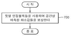
현재 블록과 공간상 인접하는 인접 블록들 중 현재 블록의 윗열에 해당하는 윗열 인접 블록들을 사용하여 공간상 예측된 화소값들을 보상한다(제700 단계). 공간상 예측된 화소값들은 현재 블록들의 인접블록들 중 윗열에 해당하는 윗열 인접블록들의 화소값들만을 이용하여 예측한 것이다. 이렇게 예측된 화소값들을 복호화 할 때, 공간상 예측의 역과정에 따라, 윗열 인접 블록들만을 사용하여 공간상 예측된 화소값들을 보상한다.In
특히, 화상의 소정 라인들 단위마다 공간상 예측된 화소값들을 보상하는 것을 특징으로 한다. 제700 단계는 전술한 화상 데이터의 공간상 예측 과정에서 화상의 소정 라인들 단위마다 윗열 인접 블록들의 화소값들을 소정 기준값(예를 들어, 화상의 계조값들 중 중간 계조값)으로 대체하여 공간상 예측한 화소값들에 대해 보상한다.In particular, the spatially predicted pixel values are compensated for every predetermined line unit of the image. In
이하, 본 발명에 의한 화상 데이터의 복호화방법을 첨부된 도면을 참조하여 다음과 같이 설명한다.Hereinafter, a method of decoding image data according to the present invention will be described with reference to the accompanying drawings.
도 17는 본 발명에 의한 화상 데이터의 복호화방법을 설명하기 위한 일 실시예의 플로차트이다.17 is a flowchart of an embodiment for explaining a decoding method of image data according to the present invention.
먼저, 화상 데이터의 비트열을 복호화한다(제800 단계).First, the bit string of the image data is decoded (step 800).
제800 단계 후에, 복호화된 화상 데이터를 역양자화 및 역변환한다(제802 단계). 변환 및 양자화 과정의 역 과정의 수행을 통해 복호화된 비트열에 대해 역양자화 및 역변환을 수행한다.After
제802 단계 후에, 현재 블록과 공간상 인접하는 인접 블록들 중 현재 블록의 윗열에 해당하는 윗열 인접 블록들을 사용하여 공간상 예측된 화소값들을 보상한다(제804 단계). 공간상 예측된 화소값들은 현재 블록들의 인접블록들 중 윗열에 해당하는 윗열 인접블록들의 화소값들만을 이용하여 예측한 것이다. 이렇게 예측된 화소값들을 복호화 할 때, 공간상 예측의 역과정에 따라, 윗열 인접 블록들만을 사 용하여 공간상 예측된 화소값들을 보상한다. 특히, 화상의 소정 라인들 단위마다 공간상 예측된 화소값들을 보상하는 것을 특징으로 한다. 제804 단계는 전술한 화상 데이터의 공간상 예측 과정에서 화상의 소정 라인들 단위마다 윗열 인접 블록들의 화소값들을 소정 기준값(예를 들어, 화상의 계조값들 중 중간 계조값)으로 대체하여 공간상 예측한 화소값들에 대해 보상한다.After
한편, 상술한 본 발명의 방법 발명은 컴퓨터에서 읽을 수 있는 코드/명령들(instructions)/프로그램으로 구현될 수 있고, 매체, 예를 들면 컴퓨터로 읽을 수 있는 기록 매체를 이용하여 상기 코드/명령들/프로그램을 동작시키는 범용 디지털 컴퓨터에서 구현될 수 있다. 상기 컴퓨터로 읽을 수 있는 기록 매체는 마그네틱 저장 매체(예를 들어, 롬, 플로피 디스크, 하드디스크, 마그네틱 테이프 등), 광학적 판독 매체(예를 들면, 시디롬, 디브이디 등) 및 캐리어 웨이브(예를 들면, 인터넷을 통한 전송)와 같은 저장 매체를 포함한다. 또한, 본 발명의 실시예들은 컴퓨터로 읽을 수 있는 코드를 내장하는 매체(들)로서 구현되어, 네트워크를 통해 연결된 다수개의 컴퓨터 시스템들이 분배되어 처리 동작하도록 할 수 있다. 본 발명을 실현하는 기능적인 프로그램들, 코드들 및 코드 세그먼트(segment)들은 본 발명이 속하는 기술 분야의 프로그래머들에 의해 쉽게 추론될 수 있다.Meanwhile, the above-described method invention of the present invention may be implemented by computer readable codes / instructions / programs, and the codes / instructions may be implemented using a medium, for example, a computer readable recording medium. / Can be implemented in a general-purpose digital computer for operating the program. The computer-readable recording medium may be a magnetic storage medium (eg, ROM, floppy disk, hard disk, magnetic tape, etc.), optical reading medium (eg, CD-ROM, DVD, etc.) and carrier wave (eg Storage media, such as through the Internet). In addition, embodiments of the present invention may be implemented as a medium (s) containing computer readable code, such that a plurality of computer systems connected through a network may be distributed and processed. Functional programs, codes and code segments for realizing the present invention can be easily inferred by programmers in the art to which the present invention belongs.
이러한 본원 발명인 화상 데이터의 공간상 예측 장치 및 방법과 그를 이용한 부호화 장치 및 방법, 화상 데이터의 공간상 예측 보상 장치 및 방법과 그를 이용한 복호화 장치 및 방법은 이해를 돕기 위하여 도면에 도시된 실시예를 참고로 설명되었으나, 이는 예시적인 것에 불과하며, 당해 분야에서 통상적 지식을 가진 자 라면 이로부터 다양한 변형 및 균등한 타 실시예가 가능하다는 점을 이해할 것이다. 따라서, 본 발명의 진정한 기술적 보호 범위는 첨부된 특허청구범위에 의해 정해져야 할 것이다.The spatial prediction apparatus and method of the image data of the present invention, the encoding apparatus and method using the same, the spatial prediction prediction apparatus and method of the image data, and the decoding apparatus and method using the same are referred to the embodiments illustrated in the drawings for clarity. Although described as being exemplary only, it will be understood by those skilled in the art that various modifications and equivalent other embodiments are possible. Therefore, the true technical protection scope of the present invention will be defined by the appended claims.
이상에서 설명한 바와 같이, 본 발명에 의한 화상 데이터의 공간상 예측 장치 및 방법과 그를 이용한 부호화 장치 및 방법, 화상 데이터의 공간상 예측 보상 장치 및 방법과 그를 이용한 복호화 장치 및 방법은 공간상 예측을 할 때에 파이프라인(pipeline) 처리가 가능하도록 함으로써, 실시간 부호화 및 그에 따른 복호화가 이루어질 수 있도록 한다.As described above, the spatial prediction apparatus and method for image data, the encoding apparatus and method using the same, the spatial prediction compensation apparatus and method for the image data, and the decoding apparatus and method using the same can perform spatial prediction. By enabling pipeline processing at this time, real-time encoding and corresponding decoding can be performed.
특히, 본 발명에 의한 화상 데이터의 공간상 예측 장치 및 그를 이용한 부호화 장치 및 방법은 화상의 에지 부분에 대한 공간상 예측시 에러 확산을 차단함으로써, 화질의 열화를 방지하도록 한다.In particular, the spatial prediction apparatus of the image data according to the present invention, and the encoding apparatus and method using the same, prevent the deterioration of the image quality by blocking the error diffusion in the spatial prediction of the edge portion of the image.
Claims (44)
Translated fromKoreanPriority Applications (7)
| Application Number | Priority Date | Filing Date | Title |
|---|---|---|---|
| KR20060033582AKR100745765B1 (en) | 2006-04-13 | 2006-04-13 | Spatial prediction device and method for image data, encoding device and method using same, Spatial prediction compensation device and method for image data, and decoding device and method using same |
| EP17151818.6AEP3190792A1 (en) | 2006-04-13 | 2007-03-27 | Apparatus and method for spatial prediction of image data, apparatus and method for encoding and decoding image data using the same |
| EP20070104959EP1845732A3 (en) | 2006-04-13 | 2007-03-27 | Apparatus and method for spatial prediction of image data, apparatus and method for encoding and decoding image data using the same |
| CN2007100958330ACN101056412B (en) | 2006-04-13 | 2007-04-05 | Spatial prediction device and method for image data, encoding and decoding device and method |
| JP2007104073AJP5048383B2 (en) | 2006-04-13 | 2007-04-11 | Image data spatial prediction apparatus and method, encoding apparatus and method using the same, image data spatial prediction compensation apparatus and method, and decoding apparatus and method using the same |
| US11/783,873US8218629B2 (en) | 2006-04-13 | 2007-04-12 | Encoding and/or decoding system, medium, and method with spatial prediction and spatial prediction compensation of image data |
| TW096113073ATWI372567B (en) | 2006-04-13 | 2007-04-13 | Apparatuses for spatial prediction of image data, encoding image data, spatial prediction compensation of image data, and decoding image data and related methods |
Applications Claiming Priority (1)
| Application Number | Priority Date | Filing Date | Title |
|---|---|---|---|
| KR20060033582AKR100745765B1 (en) | 2006-04-13 | 2006-04-13 | Spatial prediction device and method for image data, encoding device and method using same, Spatial prediction compensation device and method for image data, and decoding device and method using same |
Publications (1)
| Publication Number | Publication Date |
|---|---|
| KR100745765B1true KR100745765B1 (en) | 2007-08-02 |
Family
ID=38218471
Family Applications (1)
| Application Number | Title | Priority Date | Filing Date |
|---|---|---|---|
| KR20060033582AActiveKR100745765B1 (en) | 2006-04-13 | 2006-04-13 | Spatial prediction device and method for image data, encoding device and method using same, Spatial prediction compensation device and method for image data, and decoding device and method using same |
Country Status (6)
| Country | Link |
|---|---|
| US (1) | US8218629B2 (en) |
| EP (2) | EP3190792A1 (en) |
| JP (1) | JP5048383B2 (en) |
| KR (1) | KR100745765B1 (en) |
| CN (1) | CN101056412B (en) |
| TW (1) | TWI372567B (en) |
Cited By (1)
| Publication number | Priority date | Publication date | Assignee | Title |
|---|---|---|---|---|
| KR101226989B1 (en)* | 2010-12-28 | 2013-01-29 | 연세대학교 산학협력단 | Method and apparatus for generating prediction image by estimating gradation |
Families Citing this family (32)
| Publication number | Priority date | Publication date | Assignee | Title |
|---|---|---|---|---|
| KR101415564B1 (en)* | 2007-10-29 | 2014-08-06 | 삼성디스플레이 주식회사 | Driving device of display device and driving method thereof |
| KR101517768B1 (en)* | 2008-07-02 | 2015-05-06 | 삼성전자주식회사 | Method and apparatus for encoding video and method and apparatus for decoding video |
| JP5597968B2 (en) | 2009-07-01 | 2014-10-01 | ソニー株式会社 | Image processing apparatus and method, program, and recording medium |
| KR101474756B1 (en) | 2009-08-13 | 2014-12-19 | 삼성전자주식회사 | Method and apparatus for encoding and decoding image using large transform unit |
| KR101510108B1 (en)* | 2009-08-17 | 2015-04-10 | 삼성전자주식회사 | Method and apparatus for encoding video, and method and apparatus for decoding video |
| USRE47243E1 (en) | 2009-12-09 | 2019-02-12 | Samsung Electronics Co., Ltd. | Method and apparatus for encoding video, and method and apparatus for decoding video |
| KR101700358B1 (en)* | 2009-12-09 | 2017-01-26 | 삼성전자주식회사 | Method and apparatus for encoding video, and method and apparatus for decoding video |
| KR20110113561A (en)* | 2010-04-09 | 2011-10-17 | 한국전자통신연구원 | Intra Prediction Coding / Decoding Method Using Adaptive Filter and Its Apparatus |
| AU2011247331B2 (en) | 2010-04-26 | 2015-11-26 | Sun Patent Trust | Filtering mode for intra prediction inferred from statistics of surrounding blocks |
| US8638863B1 (en)* | 2010-05-18 | 2014-01-28 | Google Inc. | Apparatus and method for filtering video using extended edge-detection |
| KR101530284B1 (en) | 2010-07-16 | 2015-06-19 | 삼성전자주식회사 | Method and apparatus for video intra prediction encoding, and method and apparatus for video intra prediction decoding |
| US8655065B2 (en)* | 2010-10-14 | 2014-02-18 | Chimei Innolux Corporation | Image processing device using adding module for adding error diffusion value or error diffusion seed |
| KR101739579B1 (en)* | 2011-01-04 | 2017-05-24 | 에스케이 텔레콤주식회사 | Video Encoding/Decoding Method and Apparatus Using Unit-level Parallel Intra Prediction |
| BR112013016961B1 (en)* | 2011-01-12 | 2022-05-31 | Mitsubishi Electric Corporation | Image encoding and decoding devices, and image encoding and decoding methods |
| US9930366B2 (en) | 2011-01-28 | 2018-03-27 | Qualcomm Incorporated | Pixel level adaptive intra-smoothing |
| US9432699B2 (en)* | 2011-05-18 | 2016-08-30 | Nokia Technologies Oy | Methods, apparatuses and computer programs for video coding |
| EP2806639A4 (en)* | 2012-01-19 | 2016-06-01 | Mitsubishi Electric Corp | VIDEO IMAGE DECODING DEVICE, VIDEO IMAGE ENCODING DEVICE, VIDEO IMAGE DECODING METHOD, AND VIDEO IMAGE ENCODING METHOD |
| US9131073B1 (en) | 2012-03-02 | 2015-09-08 | Google Inc. | Motion estimation aided noise reduction |
| US9344729B1 (en)* | 2012-07-11 | 2016-05-17 | Google Inc. | Selective prediction signal filtering |
| JP2014179707A (en)* | 2013-03-13 | 2014-09-25 | Toshiba Corp | Image encoder, and encoding method |
| US10102613B2 (en) | 2014-09-25 | 2018-10-16 | Google Llc | Frequency-domain denoising |
| JP6501532B2 (en)* | 2015-01-23 | 2019-04-17 | キヤノン株式会社 | Image coding apparatus, image coding method and program |
| KR101703332B1 (en)* | 2015-01-30 | 2017-02-06 | 삼성전자 주식회사 | Method and apparatus for decoding video |
| KR101683177B1 (en)* | 2015-04-14 | 2016-12-06 | 삼성전자주식회사 | Method and apparatus for decoding video |
| KR101700369B1 (en)* | 2015-07-24 | 2017-01-26 | 삼성전자주식회사 | Method and apparatus for decoding video |
| KR101649276B1 (en)* | 2015-07-24 | 2016-08-18 | 삼성전자주식회사 | Method and apparatus for decoding video |
| KR101699529B1 (en)* | 2015-07-24 | 2017-01-24 | 삼성전자 주식회사 | Method and apparatus for decoding video |
| JP6669622B2 (en)* | 2016-09-21 | 2020-03-18 | Kddi株式会社 | Moving image decoding device, moving image decoding method, moving image encoding device, moving image encoding method, and computer-readable recording medium |
| KR102719084B1 (en)* | 2017-01-02 | 2024-10-16 | 한양대학교 산학협력단 | Intraprediction method and apparatus for performing adaptive filtering on reference pixels |
| US12184846B2 (en) | 2017-01-02 | 2024-12-31 | Industry-University Cooperation Foundation Hanyang University | Intra prediction method and apparatus for performing adaptive filtering on reference pixel |
| CN116074529B (en)* | 2022-01-07 | 2024-11-01 | 杭州海康威视数字技术股份有限公司 | Image encoding and decoding method, device and storage medium |
| US12289537B2 (en) | 2023-03-27 | 2025-04-29 | Samsung Electronics Co., Ltd. | Method and system for performing image signal processing |
Citations (4)
| Publication number | Priority date | Publication date | Assignee | Title |
|---|---|---|---|---|
| KR19980079371A (en)* | 1997-03-05 | 1998-11-25 | 윤종용 | Motion prediction method |
| KR19990066469A (en)* | 1998-01-26 | 1999-08-16 | 윤종용 | Reference block selection method and shape information resolution variable method for shape information pixel interpolation |
| KR20010073608A (en)* | 2000-01-19 | 2001-08-01 | 구자홍 | An Efficient Edge Prediction Methods In Spatial Domain Of Video Coding |
| KR20060066346A (en)* | 2004-12-13 | 2006-06-16 | 삼성전자주식회사 | Spatial prediction device and method for image data, encoding device and method using same, Spatial prediction compensation device and method for image data, and decoding device and method using same |
Family Cites Families (20)
| Publication number | Priority date | Publication date | Assignee | Title |
|---|---|---|---|---|
| JP3297293B2 (en) | 1996-03-07 | 2002-07-02 | 三菱電機株式会社 | Video decoding method and video decoding device |
| JP2000023163A (en) | 1998-06-30 | 2000-01-21 | Sharp Corp | Motion vector detection device |
| US6563953B2 (en) | 1998-11-30 | 2003-05-13 | Microsoft Corporation | Predictive image compression using a single variable length code for both the luminance and chrominance blocks for each macroblock |
| FI116819B (en)* | 2000-01-21 | 2006-02-28 | Nokia Corp | Procedure for transferring images and an image encoder |
| KR20020057526A (en) | 2001-01-05 | 2002-07-11 | 엘지전자 주식회사 | Method for interpolating image |
| JP4986334B2 (en)* | 2001-05-07 | 2012-07-25 | ルネサスエレクトロニクス株式会社 | Liquid crystal display device and driving method thereof |
| US6765695B2 (en)* | 2001-09-12 | 2004-07-20 | Seiko Epson Corporation | Color processing architecture and algorithms for color laser printers |
| DE10158658A1 (en) | 2001-11-30 | 2003-06-12 | Bosch Gmbh Robert | Method for directional prediction of an image block |
| JP4130780B2 (en)* | 2002-04-15 | 2008-08-06 | 松下電器産業株式会社 | Image encoding method and image decoding method |
| US7289674B2 (en) | 2002-06-11 | 2007-10-30 | Nokia Corporation | Spatial prediction based intra coding |
| JP3975188B2 (en)* | 2002-09-30 | 2007-09-12 | 三星電子株式会社 | Video coding and decoding method and apparatus using spatial prediction coding of hue |
| JP2004140473A (en)* | 2002-10-15 | 2004-05-13 | Sony Corp | Image information coding apparatus, decoding apparatus and method for coding image information, method for decoding |
| AU2004217221B2 (en) | 2003-03-03 | 2009-09-03 | Agency For Science, Technology And Research | Fast mode decision algorithm for intra prediction for advanced video coding |
| JP2004304724A (en) | 2003-04-01 | 2004-10-28 | Sony Corp | Image processing apparatus, its method and encoder |
| JP2005005844A (en)* | 2003-06-10 | 2005-01-06 | Hitachi Ltd | Computer apparatus and encoding processing program |
| CN100536573C (en)* | 2004-01-16 | 2009-09-02 | 北京工业大学 | Inframe prediction method used for video frequency coding |
| KR20050113501A (en)* | 2004-05-29 | 2005-12-02 | 삼성전자주식회사 | Syntax parser for a h.264 video decoder |
| JP2006005438A (en)* | 2004-06-15 | 2006-01-05 | Sony Corp | Image processor and method thereof |
| KR100682912B1 (en) | 2005-01-05 | 2007-02-15 | 삼성전자주식회사 | Image data encoding and decoding method and apparatus |
| KR100723403B1 (en)* | 2005-02-28 | 2007-05-30 | 삼성전자주식회사 | Method and apparatus for generating predictive image using single coding mode between color components, and method and apparatus for image and video encoding / decoding using same |
- 2006
- 2006-04-13KRKR20060033582Apatent/KR100745765B1/enactiveActive
- 2007
- 2007-03-27EPEP17151818.6Apatent/EP3190792A1/ennot_activeCeased
- 2007-03-27EPEP20070104959patent/EP1845732A3/ennot_activeCeased
- 2007-04-05CNCN2007100958330Apatent/CN101056412B/enactiveActive
- 2007-04-11JPJP2007104073Apatent/JP5048383B2/enactiveActive
- 2007-04-12USUS11/783,873patent/US8218629B2/enactiveActive
- 2007-04-13TWTW096113073Apatent/TWI372567B/enactive
Patent Citations (4)
| Publication number | Priority date | Publication date | Assignee | Title |
|---|---|---|---|---|
| KR19980079371A (en)* | 1997-03-05 | 1998-11-25 | 윤종용 | Motion prediction method |
| KR19990066469A (en)* | 1998-01-26 | 1999-08-16 | 윤종용 | Reference block selection method and shape information resolution variable method for shape information pixel interpolation |
| KR20010073608A (en)* | 2000-01-19 | 2001-08-01 | 구자홍 | An Efficient Edge Prediction Methods In Spatial Domain Of Video Coding |
| KR20060066346A (en)* | 2004-12-13 | 2006-06-16 | 삼성전자주식회사 | Spatial prediction device and method for image data, encoding device and method using same, Spatial prediction compensation device and method for image data, and decoding device and method using same |
Cited By (1)
| Publication number | Priority date | Publication date | Assignee | Title |
|---|---|---|---|---|
| KR101226989B1 (en)* | 2010-12-28 | 2013-01-29 | 연세대학교 산학협력단 | Method and apparatus for generating prediction image by estimating gradation |
Also Published As
| Publication number | Publication date |
|---|---|
| EP3190792A1 (en) | 2017-07-12 |
| TW200806041A (en) | 2008-01-16 |
| JP2007288785A (en) | 2007-11-01 |
| US20070253483A1 (en) | 2007-11-01 |
| CN101056412B (en) | 2012-10-17 |
| US8218629B2 (en) | 2012-07-10 |
| TWI372567B (en) | 2012-09-11 |
| EP1845732A2 (en) | 2007-10-17 |
| EP1845732A3 (en) | 2010-07-28 |
| JP5048383B2 (en) | 2012-10-17 |
| CN101056412A (en) | 2007-10-17 |
Similar Documents
| Publication | Publication Date | Title |
|---|---|---|
| KR100745765B1 (en) | Spatial prediction device and method for image data, encoding device and method using same, Spatial prediction compensation device and method for image data, and decoding device and method using same | |
| KR100468844B1 (en) | Optimal scanning method for transform coefficients in image and video coding/decoding | |
| KR101512324B1 (en) | Method of estimating motion vector using multiple motion vector predictors, apparatus, encoder, decoder and decoding method | |
| KR100657919B1 (en) | Spatial prediction device and method for image data, encoding device and method using same, Spatial prediction compensation device and method for image data, and decoding device and method using same | |
| JP5559139B2 (en) | Video encoding and decoding method and apparatus | |
| KR101247042B1 (en) | Prediction of transform coefficients for image compression | |
| CN1535024B (en) | Video encoding apparatus and method, and video decoding apparatus and method | |
| RU2518935C1 (en) | Method and apparatus for encoding and decoding image and method and apparatus for decoding image using adaptive coefficient scan order | |
| KR101354151B1 (en) | Method and apparatus for transforming and inverse-transforming image | |
| KR20110135787A (en) | Image Coding / Decoding System and Method Using Edge-Adaptive Transform | |
| KR20100004037A (en) | Method and apparatus for encoding video, and method and apparatus for decoding video | |
| US11134242B2 (en) | Adaptive prediction of coefficients of a video block | |
| KR20090058954A (en) | Method and device for encoding video using side matching, method and device for decoding thereof | |
| KR20220013941A (en) | Matrix-Based Intra Prediction | |
| US11882292B2 (en) | Image encoder and decoder using unidirectional prediction | |
| Nguyen et al. | A novel steganography scheme for video H. 264/AVC without distortion drift | |
| KR100682912B1 (en) | Image data encoding and decoding method and apparatus | |
| AU2011201336A1 (en) | Modulo embedding of video parameters | |
| JP5302256B2 (en) | Encoding device, decoding device, and program | |
| JP5358485B2 (en) | Image encoding device | |
| KR100939358B1 (en) | Method and apparatus for encoding and decoding an image in pixel domain | |
| US20080107183A1 (en) | Method and apparatus for detecting zero coefficients | |
| JP4205636B2 (en) | Image predictive encoding method, image predictive decode method, image encoding device, image decoding device, image encoding program, image decoding program, and computer-readable recording medium recording these programs | |
| KR101614767B1 (en) | Video encoding/decoding Apparatus and Method using second prediction based on vector quantization, and Recording Medium therefor | |
| Shleifer et al. | Novel intra prediction modes for VP10 codec |
Legal Events
| Date | Code | Title | Description |
|---|---|---|---|
| A201 | Request for examination | ||
| PA0109 | Patent application | Patent event code:PA01091R01D Comment text:Patent Application Patent event date:20060413 | |
| PA0201 | Request for examination | ||
| E701 | Decision to grant or registration of patent right | ||
| PE0701 | Decision of registration | Patent event code:PE07011S01D Comment text:Decision to Grant Registration Patent event date:20070621 | |
| GRNT | Written decision to grant | ||
| PR0701 | Registration of establishment | Comment text:Registration of Establishment Patent event date:20070727 Patent event code:PR07011E01D | |
| PR1002 | Payment of registration fee | Payment date:20070730 End annual number:3 Start annual number:1 | |
| PG1601 | Publication of registration | ||
| PR1001 | Payment of annual fee | Payment date:20100629 Start annual number:4 End annual number:4 | |
| PR1001 | Payment of annual fee | Payment date:20110711 Start annual number:5 End annual number:5 | |
| PR1001 | Payment of annual fee | Payment date:20120615 Start annual number:6 End annual number:6 | |
| FPAY | Annual fee payment | Payment date:20130624 Year of fee payment:7 | |
| PR1001 | Payment of annual fee | Payment date:20130624 Start annual number:7 End annual number:7 | |
| FPAY | Annual fee payment | Payment date:20140619 Year of fee payment:8 | |
| PR1001 | Payment of annual fee | Payment date:20140619 Start annual number:8 End annual number:8 | |
| FPAY | Annual fee payment | Payment date:20150624 Year of fee payment:9 | |
| PR1001 | Payment of annual fee | Payment date:20150624 Start annual number:9 End annual number:9 | |
| FPAY | Annual fee payment | Payment date:20160617 Year of fee payment:10 | |
| PR1001 | Payment of annual fee | Payment date:20160617 Start annual number:10 End annual number:10 | |
| FPAY | Annual fee payment | Payment date:20170619 Year of fee payment:11 | |
| PR1001 | Payment of annual fee | Payment date:20170619 Start annual number:11 End annual number:11 | |
| FPAY | Annual fee payment | Payment date:20180620 Year of fee payment:12 | |
| PR1001 | Payment of annual fee | Payment date:20180620 Start annual number:12 End annual number:12 | |
| PR1001 | Payment of annual fee | Payment date:20200618 Start annual number:14 End annual number:14 | |
| PR1001 | Payment of annual fee | Payment date:20210617 Start annual number:15 End annual number:15 | |
| PR1001 | Payment of annual fee | Payment date:20230620 Start annual number:17 End annual number:17 | |
| PR1001 | Payment of annual fee | Payment date:20250612 Start annual number:19 End annual number:19 |