KR100744250B1 - Synthetic Resin Container - Google Patents
Synthetic Resin ContainerDownload PDFInfo
- Publication number
- KR100744250B1 KR100744250B1KR1020027010765AKR20027010765AKR100744250B1KR 100744250 B1KR100744250 B1KR 100744250B1KR 1020027010765 AKR1020027010765 AKR 1020027010765AKR 20027010765 AKR20027010765 AKR 20027010765AKR 100744250 B1KR100744250 B1KR 100744250B1
- Authority
- KR
- South Korea
- Prior art keywords
- container
- eastern
- edge
- synthetic resin
- recesses
- Prior art date
- Legal status (The legal status is an assumption and is not a legal conclusion. Google has not performed a legal analysis and makes no representation as to the accuracy of the status listed.)
- Expired - Fee Related
Links
Images


Classifications
- B—PERFORMING OPERATIONS; TRANSPORTING
- B65—CONVEYING; PACKING; STORING; HANDLING THIN OR FILAMENTARY MATERIAL
- B65D—CONTAINERS FOR STORAGE OR TRANSPORT OF ARTICLES OR MATERIALS, e.g. BAGS, BARRELS, BOTTLES, BOXES, CANS, CARTONS, CRATES, DRUMS, JARS, TANKS, HOPPERS, FORWARDING CONTAINERS; ACCESSORIES, CLOSURES, OR FITTINGS THEREFOR; PACKAGING ELEMENTS; PACKAGES
- B65D1/00—Rigid or semi-rigid containers having bodies formed in one piece, e.g. by casting metallic material, by moulding plastics, by blowing vitreous material, by throwing ceramic material, by moulding pulped fibrous material or by deep-drawing operations performed on sheet material
- B65D1/02—Bottles or similar containers with necks or like restricted apertures, designed for pouring contents
- B65D1/0223—Bottles or similar containers with necks or like restricted apertures, designed for pouring contents characterised by shape
- B—PERFORMING OPERATIONS; TRANSPORTING
- B65—CONVEYING; PACKING; STORING; HANDLING THIN OR FILAMENTARY MATERIAL
- B65D—CONTAINERS FOR STORAGE OR TRANSPORT OF ARTICLES OR MATERIALS, e.g. BAGS, BARRELS, BOTTLES, BOXES, CANS, CARTONS, CRATES, DRUMS, JARS, TANKS, HOPPERS, FORWARDING CONTAINERS; ACCESSORIES, CLOSURES, OR FITTINGS THEREFOR; PACKAGING ELEMENTS; PACKAGES
- B65D23/00—Details of bottles or jars not otherwise provided for
- B65D23/10—Handles
- B65D23/102—Gripping means formed in the walls, e.g. roughening, cavities, projections
- B—PERFORMING OPERATIONS; TRANSPORTING
- B65—CONVEYING; PACKING; STORING; HANDLING THIN OR FILAMENTARY MATERIAL
- B65D—CONTAINERS FOR STORAGE OR TRANSPORT OF ARTICLES OR MATERIALS, e.g. BAGS, BARRELS, BOTTLES, BOXES, CANS, CARTONS, CRATES, DRUMS, JARS, TANKS, HOPPERS, FORWARDING CONTAINERS; ACCESSORIES, CLOSURES, OR FITTINGS THEREFOR; PACKAGING ELEMENTS; PACKAGES
- B65D79/00—Kinds or details of packages, not otherwise provided for
- B65D79/005—Packages having deformable parts for indicating or neutralizing internal pressure-variations by other means than venting
- B65D79/008—Packages having deformable parts for indicating or neutralizing internal pressure-variations by other means than venting the deformable part being located in a rigid or semi-rigid container, e.g. in bottles or jars
- B65D79/0084—Packages having deformable parts for indicating or neutralizing internal pressure-variations by other means than venting the deformable part being located in a rigid or semi-rigid container, e.g. in bottles or jars in the sidewall or shoulder part thereof
- B—PERFORMING OPERATIONS; TRANSPORTING
- B65—CONVEYING; PACKING; STORING; HANDLING THIN OR FILAMENTARY MATERIAL
- B65D—CONTAINERS FOR STORAGE OR TRANSPORT OF ARTICLES OR MATERIALS, e.g. BAGS, BARRELS, BOTTLES, BOXES, CANS, CARTONS, CRATES, DRUMS, JARS, TANKS, HOPPERS, FORWARDING CONTAINERS; ACCESSORIES, CLOSURES, OR FITTINGS THEREFOR; PACKAGING ELEMENTS; PACKAGES
- B65D2501/00—Containers having bodies formed in one piece
- B65D2501/0009—Bottles or similar containers with necks or like restricted apertures designed for pouring contents
- B65D2501/0018—Ribs
- B65D2501/0036—Hollow circonferential ribs
- B—PERFORMING OPERATIONS; TRANSPORTING
- B65—CONVEYING; PACKING; STORING; HANDLING THIN OR FILAMENTARY MATERIAL
- B65D—CONTAINERS FOR STORAGE OR TRANSPORT OF ARTICLES OR MATERIALS, e.g. BAGS, BARRELS, BOTTLES, BOXES, CANS, CARTONS, CRATES, DRUMS, JARS, TANKS, HOPPERS, FORWARDING CONTAINERS; ACCESSORIES, CLOSURES, OR FITTINGS THEREFOR; PACKAGING ELEMENTS; PACKAGES
- B65D2501/00—Containers having bodies formed in one piece
- B65D2501/0009—Bottles or similar containers with necks or like restricted apertures designed for pouring contents
- B65D2501/0018—Ribs
- B65D2501/0045—Solid ribs
- B—PERFORMING OPERATIONS; TRANSPORTING
- B65—CONVEYING; PACKING; STORING; HANDLING THIN OR FILAMENTARY MATERIAL
- B65D—CONTAINERS FOR STORAGE OR TRANSPORT OF ARTICLES OR MATERIALS, e.g. BAGS, BARRELS, BOTTLES, BOXES, CANS, CARTONS, CRATES, DRUMS, JARS, TANKS, HOPPERS, FORWARDING CONTAINERS; ACCESSORIES, CLOSURES, OR FITTINGS THEREFOR; PACKAGING ELEMENTS; PACKAGES
- B65D2501/00—Containers having bodies formed in one piece
- B65D2501/0009—Bottles or similar containers with necks or like restricted apertures designed for pouring contents
- B65D2501/0081—Bottles of non-circular cross-section
Landscapes
- Engineering & Computer Science (AREA)
- Mechanical Engineering (AREA)
- Ceramic Engineering (AREA)
- Containers Having Bodies Formed In One Piece (AREA)
- Details Of Rigid Or Semi-Rigid Containers (AREA)
Abstract
Translated fromKoreanDescription
Translated fromKorean본 발명은 각종 열가소성 합성수지의 블로성형에 의해 성형된 장통(長筒)상의 동부(胴部)를 가지는 대용량(예를 들면, 내용량 약 2리터)의 통상 용기로서, 손가락에 의해 파지되어 사용되는 합성수지제 용기의 동부 구조의 개량에 관한 것이다.
The present invention is a general container of a large capacity (for example, about 2 liters of contents) having a long barrel-shaped eastern part molded by blow molding of various thermoplastic synthetic resins, and is used by a finger held by a finger. The improvement of the eastern structure of the container.
종래의 이러한 종류의 대형 용기에서는 내압의 증감에 의해 동부 주벽의 변형을 방지하기 위하여 동부 주벽에 변형 흡수역과 보강 리브를 형성함과 동시에, 용기의 취급을 용이하게 하기 위해, 동부측면에 파지용 핸들을 돌설(突設)하는 것이 일반적으로 행해지고 있다.In the conventional large container of this kind, a handle for holding on the eastern side in order to facilitate the handling of the container while forming a deformation absorbing zone and a reinforcing rib in the eastern circumferential wall to prevent deformation of the eastern circumferential wall by increasing or decreasing the internal pressure. It is generally done to protrude.
그러나, 동부측면에 돌설된 파지용 핸들은 그것이 동부의 연속일체로 블로성형된 구조임에도, 별체의 핸들을 조립한 구조의 것에서 보다도 구조가 복잡하게 되고, 용기 1개당의 사용수지량도 많게 될 뿐만 아니라, 상기 내압의 증감에 의한 동부 주벽의 변형흡수역의 형성부위와 변형흡수기기에도 제약이 발생하게 되는 등의 문제를 내재하고 있다.
However, the grip handle on the eastern side has a structure that is blow-molded in the eastern continuous one, but the structure becomes more complicated than that of the structure in which the separate handle is assembled, and the amount of used resin per container also increases. In addition, there is a problem in that the formation of the deformation absorption zone of the eastern circumferential wall and the deformation absorber caused by the increase and decrease of the internal pressure cause a restriction.
본 발명에서는 동부를 가지는 용기에서 용기 동부의 중심선에 대하여 대칭면이 되는 동부의 좌우측면에 대한 동부 중앙을 포함하는 영역에, 용기 내압의 변화에 의한 동부주벽의 변형을 흡수완화하는 변형흡수용의 요홈부(요함部)가 닮은꼴로 형성되어 있다. 이 변형흡수용의 각 요홈부는, 저면이 주벽의 모선방향과 주방향의 적어도 하나의 일방에 대해서 대략 완만한 요호면(凹弧面)으로 되어 있다. 또한 상기 요홈부의 상하단에는 동부 주면으로부터 요홈부의 저면을 향하여 서서히 철출(凸出)높이를 감소시킬 수 있음과 동시에, 상기 상하선으로부터 저면을 향하여 서서히 횡폭을 감소시킬 수 있고, 또한 정면형상이 대략 삼각형의 철출면으로 형성된 보강부가 형성되어 있다.In the present invention, in the container having the eastern part, the region for the eastern part of the eastern wall, which is symmetrical with respect to the center line of the eastern part of the container, absorbs and deforms the deformation of the eastern circumferential wall due to the change in the internal pressure of the container. Grooves are formed in a similar shape. Each recessed portion for strain absorption is a recessed surface that is substantially smooth with respect to at least one of the bus bar direction and the main direction of the main wall. In addition, at the upper and lower ends of the groove portion, the height of evacuation can be gradually decreased from the eastern main surface toward the bottom surface of the groove portion, and at the same time, the horizontal width can be gradually decreased from the upper and lower lines toward the bottom surface, and the front shape is approximately triangular. The reinforcement part formed with the withdrawal surface of is formed.
용기의 중심축선에 대하여 대칭이 되는 좌측면과 우측면을 가지는 동부를 포함하는 합성수지제 담체 용기에 있어서, 그 좌측면 및 우측면의 각각에 대하여 동부 중앙대를 포함하는 영역에 용기내압의 변화에 대응하는 변형 흡수용의 요홈부가 형성되어 있다. 그 좌측면의 요홈부와 우측면의 요홈부는 닮은꼴이며, 동일한 치수이다. 각 요홈부의 각각은 상연(上緣), 하연(下緣) 및 저면을 포함하고, 각 저면은 주벽의 모선방향과 주방향의 적어도 어느 한쪽에 대해서 대략 완만한 요호면으로 되어 있다. 요홈부의 각각에는 그 상부 및 하부로 철출면의 보강부가 형성되어 있고, 각 보강부는 요홈부의 상연 및 하연으로부터 저면을 향하여 서서히 감소되는 철출높이를 가지고, 또한 상연 및 하연으로부터 저면을 향하여 서서히 감소되는 횡 폭을 가지며, 그것에 의해 보강부는 대략 삼각형의 정면형상을 가진다.A synthetic resin carrier container comprising a eastern portion having a left side and a right side that are symmetrical with respect to the center axis of the vessel, the deformation corresponding to a change in the vessel internal pressure in an area including the eastern central zone with respect to each of the left and right sides thereof. Absorption grooves are formed. The recessed portion on the left side and the recessed portion on the right side are similar in shape and have the same dimensions. Each groove portion includes an upper edge, a lower edge, and a bottom surface, and each bottom surface is a rough surface roughly at least in either the bus bar direction and the main direction of the main wall. Each of the grooves has a reinforcement portion of the withdrawal surface formed at the upper and lower portions thereof, and each reinforcement portion has a withdrawal height that gradually decreases from the upper and lower edges of the groove portion toward the bottom, and also gradually decreases from the upper and lower edges toward the bottom. Width, whereby the reinforcement has an approximately triangular front shape.
요홈부의 저면에는 종방향의 철출리브가 형성되어, 손가락 끝의 미끄러짐을방지하여도 좋다.On the bottom of the groove portion, longitudinal ribs may be formed to prevent the fingertip from slipping.
상기 저면의 중앙부분에는 주방향으로 철출리브가 형성되어 있어도 좋다.In the center portion of the bottom face, iron ribs may be formed in the circumferential direction.
본 발명은 상술한 구성으로 하기 때문에 한쪽 손의 손가락, 손바닥으로 용기동부의 대략 중앙을 전측 및 후측으로부터 파지하는 것에 의해, 대용량, 대중량의 용기에도 상관하지 않고 안전, 확실하게 파지하는 것이 가능하다.Since the present invention has the above-described configuration, by holding the finger and palm of one hand about the center of the container eastern from the front side and the rear side, it is possible to securely and reliably hold the container regardless of a large capacity or a large weight container. .
또한 변형 흡수용의 요홈부를 전술하는 것과 같이 특수한 곡면구성으로 하기 때문에 내고압용기의 경판(end plate)과 동일한 기능을 발현시키고, 용기 내압의 변동에 의해 용기 동부의 변형과 함께 파지시의 극단적인 변형을 방지할 수 있어, 핸들의 부설을 필요하지 않기 때문에 사용수지량의 감소를 꾀할 수 있다.In addition, since the groove for absorbing deformation has a special curved structure as described above, it exhibits the same function as the end plate of the high-pressure container, and the extreme pressure at the time of gripping together with the deformation of the eastern part of the container due to the change in the internal pressure of the container. Since the deformation can be prevented and the handles are not laid, the amount of used resin can be reduced.
또한 핸들부가 형성되지 않기 때문에 일정용량에 대한 용기외형을 유도할 수 있게 되고, 돌출하는 핸들부가 없기 때문에 용기의 수납스페이스의 협소화를 꾀할 수 있다.
In addition, since the handle portion is not formed, it is possible to induce the appearance of the container with respect to a certain capacity, and since there is no protruding handle portion, it is possible to narrow the storage space of the container.
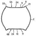
도 1은 본 발명의 보틀의 좌측면도이다.1 is a left side view of the bottle of the present invention.
도 2는 도 1에 도시된 용기의 정면도이다.FIG. 2 is a front view of the container shown in FIG. 1. FIG.
도 3은 도 1 중 A-A선 절단 단면도이다.3 is a cross-sectional view taken along the line A-A in FIG.
도 4는 도 1 중 B-B선 절단 단면도이다.
4 is a cross-sectional view taken along line BB of FIG. 1.
도 1 내지 도 4는 본 발명의 실시의 일예이다. 용량 2리터의 PET 수지제 2축 연신 블로성형 보틀을 나타내고 있다.1 to 4 illustrate one embodiment of the present invention. The biaxially stretched blow molding bottle made of PET resin with a capacity of 2 liters is shown.
도시예의 용기 주체(1)는 장통상의 동부(2), 동부의 위에 설치된 견부(肩部: 3), 그 견부의 위에 설치된 구경부(口頸部: 4), 및 상기 동부의 밑에 설치된 저부(5)로 이루어진다. 이들 동부(2), 견부(3) 및 구경부(4)의 구체적 구조는 본 발명의 요부와 직접 관련이 없기 때문에, 주지의 합성수지제 보틀의 동부, 견부, 구경부와 치환하여 이해하여도 좋다.The container
동부(2)는 용기의 중심축선 O-O에 대하여 대칭으로 되는 좌측면(6A)과 우측면(6B)을 가지고 있다. 좌측면(6A)에서는 동부 중앙역을 포함하는 영역(7)에 변형 흡수용 요홈부(9)가 형성되어 있고, 우측면(6B)에는 동부 중앙역을 포함하는 영역(8)에 변형 흡수용 요홈부(10)가 형성되어 있다. 상온보다 높은 온도의 내용액을 용기에 충진하고 용기를 밀봉한 후, 내용액의 온도가 내려가면 용기내의 압력이 저하한다. 용기내의 압력이 저하하는 때에 요홈부 각각(9, 10)은 내방으로 휘어지는 것이 가능하며, 이것에 의해 용기 내압의 변화에 의한 동부주벽의 변형을 흡수완화한다. 또한 구경부(4)는 고온충진에 대응할 수 있도록 열결정화되어 있어도 좋다. 동부의 요홈부 9와 요홈부 10은 닮은꼴이며, 동일한 치수를 가지고 있다. 요홈부(9, 10), 각각은 상연(14), 하연(15), 좌연(20) 및 우연(21)을 가지고 있다. 도시 실시예에서 그 상연(14), 하연(15), 좌연(20) 및 우연(21)에 둘러싸이는 요홈부(9, 10)의 각각은 종길이의 단형상에 형성되어 있으나, 본 발명은 이것에 제한되지 않고 장원형 등이어도 좋다.The
변형 흡수용 요홈부(9, 10)의 각각은, 저면(13)을 가지고 있다. 저면(13)은 횡단면에서는 도 3에 도시된 것과 같이 주방향으로 전체로서 대략 완만한 원호면(11)을 형성하고, 동부 모선방향의 단면에서는 도 4에 도시된 것처럼 대략 평면(12)을 형성한다.Each of the
요홈부(9, 10)의 상연(14)과 하연(15)의 각각에는 보강부(18 19)가 형성되어 있다. 보강부(18, 19)의 각각은 대략 삼각형의 정면형상을 가지며, 외측으로 팽출(膨出)되어 있고, 철출높이 H와 횡폭 W를 가진다. 보강부(18, 19)의 각각의 상기 철출높이 H는 동부 주면(16, 17)로부터 요홈부(9, 10)의 저면(13)을 향하여 서서히 감소되어 있다. 보강부(18, 19)의 각각의 횡폭 W는 상기 상연(14) 또는 하연(15)으로부터 요홈부(9, 10)의 저면(13)을 향하여 서서히 감소되어 있다.Reinforcing
요홈부(9, 10)의 좌연(20)과 우연(21)의 각각은 소철원호(小凸圓弧)의 횡단면을 가지는 리브이다. 대인이 한쪽 손의 손바닥으로 상기 요홈부(9, 10)에 대하여 용기동부(2)를 파지한 때에 손목뼈와 중간 손뼈의 관절 상당부의 손바닥 부분이 요홈부(9, 10) 내에 소망하는 위치로 좌연(20)과 우연(21) 각각은 설정되어 있다.Each of the
상기 요홈부(9, 10)의 저부(13) 각각에는 종방향으로 높이가 낮은 돌출리브(22, 23)이 복수 형성되어 있어, 파지시에 손가락 끝의 미끄러짐을 방지하고 있다.A plurality of protruding
또한 상기 저면(13), 각각의 중앙에는 주방향으로 돌출리브(24)가 형성되어 있다.In addition, protruding
상기 돌출리브 22, 23 및 돌출리브 24의 수는 도시예에 한정된 것이 아니며, 그 형상도 도시예의 형상으로 한장되지 않는다. 돌출리브 22, 23은 파지시의 손가락 끝의 미끄러짐을 방지할 수 있는 것이면, 어떤 형상, 돌출높이여도 좋으며, 돌출리브 24는 요홈부(9, 10)의 저면(13)을 보강할 수 있는 것이면, 어떤 형상, 돌출높이여도 좋다.The number of the
본 발명의 요홈부(9, 10)의 저면은 주벽의 모선방향과 주방향의 적어도 일방에 대하여 대략 완만한 요호면으로 되어 있다. 다시 요홈부(9, 10)의 각각의 상하연(14, 15)으로부터 저면(13)에 걸쳐 외방으로 돌출하는 돌출면(18, 19)이 형성되어 있다. 따라서 요홈부(9, 10)가 내고압용기의 경판(end plate)과 동일한 내압강도를 가지게 된다. 따라서 요홈부(9, 10)는 용기내압의 변화와 손바닥에 의한 파지의 외압으로 충분히 대향할 수 있는 강도를 보유한다.The bottom face of the
상기 실시예의 용기는 PET 수지제이나, 본 발명은 PET 수지제 용기에 한정되지 않고, 그 외의 폴리에스테르 수지, 폴리올레핀 수지, 폴리카보네이트 수지 등, 공지의 수지에 의해 제조할 수 있다. 본 발명의 용기는 상기 수지가 단층이어도 좋고, 다층이어도 좋다. 예를 들면 본 발명의 용기는 PET 수지와 MDX-6 나일론 수지, 에틸렌 비닐 알콜 공중합체 수지 등 산소차폐 재료의 다층이어도 좋다. 공지 수지에 상기 산소차폐 재료를 플레이트하는 것도 가능하다. 다시 재활용 PET 등을 이용하는 것도 가능하다.Although the container of the said Example is made of PET resin, this invention is not limited to PET resin container, It can manufacture by well-known resin, such as other polyester resin, polyolefin resin, polycarbonate resin. The container of the present invention may be a single layer or a multilayer. For example, the container of this invention may be a multilayer of oxygen shielding materials, such as PET resin, MDX-6 nylon resin, and ethylene vinyl alcohol copolymer resin. It is also possible to plate the oxygen shielding material in a known resin. It is also possible to use recycled PET again.
또한, 도 3 및 도 4에서 용기벽의 두께는 구조를 명시하기 위해 실물의 벽두께의 수배 이상의 두께로 묘사되어 있으며, 도시된 벽두께는 상기 강도와는 직접 관계가 없다. 또한 도 2에서 점선에 의해 표시된 종단면 형상은 도 1 중 B-B선을 따라서 절단된 경우의 것이다.In addition, the thickness of the container wall in Figures 3 and 4 is depicted as several times the thickness of the actual wall thickness to specify the structure, the wall thickness shown is not directly related to the strength. In addition, the longitudinal cross-sectional shape shown by the dotted line in FIG. 2 is a case cut along the B-B line | wire in FIG.
Claims (6)
Translated fromKoreanApplications Claiming Priority (1)
| Application Number | Priority Date | Filing Date | Title |
|---|---|---|---|
| PCT/JP2000/009028WO2002049926A1 (en) | 2000-12-20 | 2000-12-20 | Container made of synthetic resin |
Publications (2)
| Publication Number | Publication Date |
|---|---|
| KR20020089563A KR20020089563A (en) | 2002-11-29 |
| KR100744250B1true KR100744250B1 (en) | 2007-07-30 |
Family
ID=11736812
Family Applications (1)
| Application Number | Title | Priority Date | Filing Date |
|---|---|---|---|
| KR1020027010765AExpired - Fee RelatedKR100744250B1 (en) | 2000-12-20 | 2000-12-20 | Synthetic Resin Container |
Country Status (10)
| Country | Link |
|---|---|
| US (1) | US6981604B2 (en) |
| EP (1) | EP1346918B1 (en) |
| JP (1) | JP4514405B2 (en) |
| KR (1) | KR100744250B1 (en) |
| CN (1) | CN1201975C (en) |
| AU (2) | AU2002256553B2 (en) |
| CA (1) | CA2429834C (en) |
| DE (1) | DE60039639D1 (en) |
| TW (1) | TW587048B (en) |
| WO (1) | WO2002049926A1 (en) |
Cited By (1)
| Publication number | Priority date | Publication date | Assignee | Title |
|---|---|---|---|---|
| KR200445978Y1 (en) | 2008-01-23 | 2009-09-14 | 샘표식품 주식회사 | Plastic bottle |
Families Citing this family (34)
| Publication number | Priority date | Publication date | Assignee | Title |
|---|---|---|---|---|
| US7377399B2 (en) | 2003-02-10 | 2008-05-27 | Amcor Limited | Inverting vacuum panels for a plastic container |
| US6920992B2 (en)* | 2003-02-10 | 2005-07-26 | Amcor Limited | Inverting vacuum panels for a plastic container |
| EP1688354B1 (en)* | 2003-11-26 | 2012-11-07 | Yoshino Kogyosho Co., Ltd. | Synthetic resin heat-resistant bottle type container |
| US7347339B2 (en)* | 2004-04-01 | 2008-03-25 | Constar International, Inc. | Hot-fill bottle having flexible portions |
| US20060070977A1 (en)* | 2004-10-01 | 2006-04-06 | Graham Packaging Company, L.P. | Oval container |
| US7296703B2 (en)* | 2005-02-14 | 2007-11-20 | Amcor Limited | Hot-fillable blow molded container with pinch-grip vacuum panels |
| KR101230677B1 (en)* | 2005-02-18 | 2013-02-07 | 도요 세이칸 가부시키가이샤 | Container |
| CA2540427C (en)* | 2005-03-21 | 2014-12-30 | Ocean Spray Cranberries, Inc. | Bottle with reinforced top portion |
| JP4940647B2 (en)* | 2005-12-19 | 2012-05-30 | 大日本印刷株式会社 | Plastic bottle containers |
| JP4936242B2 (en)* | 2006-04-27 | 2012-05-23 | 株式会社吉野工業所 | Plastic bottle |
| JP4962942B2 (en)* | 2006-06-29 | 2012-06-27 | 株式会社吉野工業所 | Synthetic resin housing |
| US7861876B2 (en)* | 2006-09-22 | 2011-01-04 | Ball Corporation | Bottle with intruding margin vacuum responsive panels |
| US9340314B2 (en)* | 2006-09-27 | 2016-05-17 | Plastipak Packaging, Inc. | Container hoop support |
| JP4796946B2 (en)* | 2006-11-30 | 2011-10-19 | 信越化学工業株式会社 | Pellicle storage container |
| US8141733B2 (en)* | 2007-01-18 | 2012-03-27 | The Coca-Cola Company | Beverage container having circular arcs |
| WO2008115810A1 (en)* | 2007-03-16 | 2008-09-25 | Constar International Inc. | Container having meta-stable panels |
| US7832583B2 (en)* | 2007-10-16 | 2010-11-16 | Graham Packaging Company, L.P. | Hot-fillable container and method of making |
| USD647406S1 (en) | 2009-06-30 | 2011-10-25 | Ocean Spray Cranberries, Inc. | Bottle |
| US8567624B2 (en)* | 2009-06-30 | 2013-10-29 | Ocean Spray Cranberries, Inc. | Lightweight, high strength bottle |
| USD648219S1 (en) | 2009-06-30 | 2011-11-08 | Ocean Spray Cranberries, Inc. | Bottle |
| JP5377239B2 (en)* | 2009-11-13 | 2013-12-25 | サントリー食品インターナショナル株式会社 | Bottle type container |
| USD643723S1 (en) | 2010-02-26 | 2011-08-23 | Pepsico, Inc. | Bottle |
| USD648222S1 (en) | 2010-04-21 | 2011-11-08 | Pepsico, Inc. | Bottle |
| US8505757B2 (en)* | 2011-02-16 | 2013-08-13 | Amcor Limited | Shoulder rib to direct top load force |
| US8556097B2 (en)* | 2011-02-16 | 2013-10-15 | Amcor Limited | Container having vacuum panel with balanced vacuum and pressure response |
| JP6342112B2 (en)* | 2012-12-03 | 2018-06-13 | サントリーホールディングス株式会社 | Resin container |
| JP6131627B2 (en)* | 2013-02-18 | 2017-05-24 | 大日本印刷株式会社 | Plastic bottle |
| USD727736S1 (en) | 2013-03-15 | 2015-04-28 | Ocean Spray Cranberries, Inc. | Bottle |
| CN105793161A (en)* | 2013-12-05 | 2016-07-20 | 雀巢产品技术援助有限公司 | Vacuum-resistant containers having offset horizontal ribs and panels |
| USD772071S1 (en) | 2014-10-24 | 2016-11-22 | Pepsico, Inc. | Bottle |
| JP6462366B2 (en)* | 2014-12-26 | 2019-01-30 | キリン株式会社 | Plastic bottle |
| EP3613140A4 (en)* | 2017-04-17 | 2021-01-06 | Sunfolding, Inc. | CONTROL SYSTEM AND PROCEDURES FOR SOLDIERS |
| CN117068526A (en)* | 2022-05-09 | 2023-11-17 | 宜兰食品工业股份有限公司 | Food container and food container production process |
| CN117068532A (en)* | 2022-05-09 | 2023-11-17 | 宜兰食品工业股份有限公司 | Food container and food container production process |
Citations (4)
| Publication number | Priority date | Publication date | Assignee | Title |
|---|---|---|---|---|
| JPH08318953A (en)* | 1995-05-18 | 1996-12-03 | Marusan Shokuhin Kk | Container for liquid seasoning |
| JPH10203520A (en) | 1997-01-17 | 1998-08-04 | Dainippon Printing Co Ltd | Plastic bottle |
| JPH10305823A (en) | 1997-05-01 | 1998-11-17 | Hokkai Can Co Ltd | Synthetic resin bottle |
| JPH10329820A (en) | 1997-05-30 | 1998-12-15 | Shoji Iwai | Thin plastic bottle |
Family Cites Families (20)
| Publication number | Priority date | Publication date | Assignee | Title |
|---|---|---|---|---|
| GB2024087B (en)* | 1978-06-29 | 1982-08-25 | Yoshino Kogyosho Co Ltd | Blow moulding polyester container |
| CA1186251A (en)* | 1980-12-26 | 1985-04-30 | Akiho Ota | Container of polyethylene terephthalate or saturated polyester resin |
| US5199587A (en)* | 1985-04-17 | 1993-04-06 | Yoshino Kogyosho Co., Ltd. | Biaxial-orientation blow-molded bottle-shaped container with axial ribs |
| US4993565A (en)* | 1986-04-14 | 1991-02-19 | Yoshino Kogyosho Co., Ltd. | Biaxial-orientation blow-molded bottle-shaped container having opposed recesses and grooves for stable gripping and anti-buckling stiffness |
| EP0279628B1 (en)* | 1987-02-17 | 1993-05-05 | Yoshino Kogyosho Co., Ltd. | Pressure resistant bottle-shaped container |
| US4804097A (en)* | 1987-08-19 | 1989-02-14 | Sewell Plastics, Inc. | Bottle with non-everting hand grip |
| JPH0728086Y2 (en)* | 1990-05-14 | 1995-06-28 | 東洋製罐株式会社 | Resin bottle container |
| JPH0410013U (en)* | 1990-05-17 | 1992-01-28 | ||
| GB2258209A (en)* | 1991-07-30 | 1993-02-03 | Sipa Spa | Plastic bottle for containing either carbonated or non-carbonated beverages |
| US5226550A (en)* | 1992-06-23 | 1993-07-13 | Silgan Plastics Corporation | Synthetic resin bottle with handgrips |
| US5758790A (en)* | 1993-09-03 | 1998-06-02 | Mott's Inc. | Bottle-shaped container |
| US5392937A (en)* | 1993-09-03 | 1995-02-28 | Graham Packaging Corporation | Flex and grip panel structure for hot-fillable blow-molded container |
| US5472105A (en)* | 1994-10-28 | 1995-12-05 | Continental Pet Technologies, Inc. | Hot-fillable plastic container with end grip |
| JPH09328115A (en)* | 1996-06-11 | 1997-12-22 | Mitsubishi Plastics Ind Ltd | Plastic square bottle |
| JP3769736B2 (en)* | 1996-07-27 | 2006-04-26 | 株式会社吉野工業所 | Hollow container that can be easily crushed |
| US5971184A (en)* | 1997-10-28 | 1999-10-26 | Continental Pet Technologies, Inc. | Hot-fillable plastic container with grippable body |
| USD402896S (en)* | 1997-12-24 | 1998-12-22 | Ball Corporation | Octagonal container with pinch grip |
| US6223920B1 (en)* | 1998-05-19 | 2001-05-01 | Sclimalbach-Lubeca, Ag | Hot-fillable blow molded container with pinch-grip vacuum panels |
| JP3608420B2 (en)* | 1999-02-24 | 2005-01-12 | 東洋製罐株式会社 | Plastic container |
| US6439413B1 (en)* | 2000-02-29 | 2002-08-27 | Graham Packaging Company, L.P. | Hot-fillable and retortable flat paneled jar |
- 2000
- 2000-12-20KRKR1020027010765Apatent/KR100744250B1/ennot_activeExpired - Fee Related
- 2000-12-20DEDE60039639Tpatent/DE60039639D1/ennot_activeExpired - Lifetime
- 2000-12-20AUAU2002256553Apatent/AU2002256553B2/ennot_activeCeased
- 2000-12-20EPEP00993928Apatent/EP1346918B1/ennot_activeExpired - Lifetime
- 2000-12-20JPJP2002551440Apatent/JP4514405B2/ennot_activeExpired - Lifetime
- 2000-12-20WOPCT/JP2000/009028patent/WO2002049926A1/enactiveIP Right Grant
- 2000-12-20CNCNB008190941Apatent/CN1201975C/ennot_activeExpired - Fee Related
- 2000-12-20USUS10/399,387patent/US6981604B2/ennot_activeExpired - Lifetime
- 2000-12-20AUAU5655302Apatent/AU5655302A/enactivePending
- 2000-12-20CACA002429834Apatent/CA2429834C/ennot_activeExpired - Lifetime
- 2001
- 2001-12-18TWTW090131417Apatent/TW587048B/ennot_activeIP Right Cessation
Patent Citations (4)
| Publication number | Priority date | Publication date | Assignee | Title |
|---|---|---|---|---|
| JPH08318953A (en)* | 1995-05-18 | 1996-12-03 | Marusan Shokuhin Kk | Container for liquid seasoning |
| JPH10203520A (en) | 1997-01-17 | 1998-08-04 | Dainippon Printing Co Ltd | Plastic bottle |
| JPH10305823A (en) | 1997-05-01 | 1998-11-17 | Hokkai Can Co Ltd | Synthetic resin bottle |
| JPH10329820A (en) | 1997-05-30 | 1998-12-15 | Shoji Iwai | Thin plastic bottle |
Cited By (1)
| Publication number | Priority date | Publication date | Assignee | Title |
|---|---|---|---|---|
| KR200445978Y1 (en) | 2008-01-23 | 2009-09-14 | 샘표식품 주식회사 | Plastic bottle |
Also Published As
| Publication number | Publication date |
|---|---|
| AU2002256553B2 (en) | 2006-10-26 |
| EP1346918A4 (en) | 2007-08-08 |
| CN1434780A (en) | 2003-08-06 |
| TW587048B (en) | 2004-05-11 |
| JPWO2002049926A1 (en) | 2004-04-22 |
| AU5655302A (en) | 2002-07-01 |
| CN1201975C (en) | 2005-05-18 |
| DE60039639D1 (en) | 2008-09-04 |
| US6981604B2 (en) | 2006-01-03 |
| CA2429834A1 (en) | 2002-06-27 |
| KR20020089563A (en) | 2002-11-29 |
| EP1346918B1 (en) | 2008-07-23 |
| US20040050851A1 (en) | 2004-03-18 |
| JP4514405B2 (en) | 2010-07-28 |
| EP1346918A1 (en) | 2003-09-24 |
| WO2002049926A1 (en) | 2002-06-27 |
| CA2429834C (en) | 2008-10-07 |
Similar Documents
| Publication | Publication Date | Title |
|---|---|---|
| KR100744250B1 (en) | Synthetic Resin Container | |
| AU2006285940B2 (en) | Synthetic resin square bottle body | |
| AU2002332323B2 (en) | Synthetic resin container with shape retainability | |
| JP4046989B2 (en) | Pinch grip type bottle type container | |
| KR101230677B1 (en) | Container | |
| US20090230084A1 (en) | Plastic container having enhanced crush resistance and pouring stability | |
| KR101267463B1 (en) | Synthetic resin bottle body | |
| JP4876604B2 (en) | container | |
| AU2008255764B2 (en) | Synthetic resin bottle | |
| JPH0423765Y2 (en) | ||
| JP4393731B2 (en) | Synthetic resin container with excellent shape retention | |
| JP5177389B2 (en) | Pinch grip type bottle container | |
| JP4692749B2 (en) | Pinch grip type bottle container | |
| JP6467538B2 (en) | Plastic bottle | |
| JP3819207B2 (en) | Flat thin blow bottle | |
| JP6676925B2 (en) | Synthetic resin bottle | |
| JP6786633B2 (en) | Plastic bottle | |
| JP2002154515A (en) | Bottle made of synthetic resin | |
| JPH11348954A (en) | Blow molded bottle | |
| JPH11255227A (en) | Synthetic resin reinforced panel and synthetic resin bottle using this synthetic resin reinforced panel |
Legal Events
| Date | Code | Title | Description |
|---|---|---|---|
| PA0105 | International application | St.27 status event code:A-0-1-A10-A15-nap-PA0105 | |
| P11-X000 | Amendment of application requested | St.27 status event code:A-2-2-P10-P11-nap-X000 | |
| P13-X000 | Application amended | St.27 status event code:A-2-2-P10-P13-nap-X000 | |
| PG1501 | Laying open of application | St.27 status event code:A-1-1-Q10-Q12-nap-PG1501 | |
| A201 | Request for examination | ||
| P11-X000 | Amendment of application requested | St.27 status event code:A-2-2-P10-P11-nap-X000 | |
| P13-X000 | Application amended | St.27 status event code:A-2-2-P10-P13-nap-X000 | |
| PA0201 | Request for examination | St.27 status event code:A-1-2-D10-D11-exm-PA0201 | |
| E902 | Notification of reason for refusal | ||
| PE0902 | Notice of grounds for rejection | St.27 status event code:A-1-2-D10-D21-exm-PE0902 | |
| P11-X000 | Amendment of application requested | St.27 status event code:A-2-2-P10-P11-nap-X000 | |
| P13-X000 | Application amended | St.27 status event code:A-2-2-P10-P13-nap-X000 | |
| E701 | Decision to grant or registration of patent right | ||
| PE0701 | Decision of registration | St.27 status event code:A-1-2-D10-D22-exm-PE0701 | |
| GRNT | Written decision to grant | ||
| PR0701 | Registration of establishment | St.27 status event code:A-2-4-F10-F11-exm-PR0701 | |
| PR1002 | Payment of registration fee | St.27 status event code:A-2-2-U10-U12-oth-PR1002 Fee payment year number:1 | |
| PG1601 | Publication of registration | St.27 status event code:A-4-4-Q10-Q13-nap-PG1601 | |
| PR1001 | Payment of annual fee | St.27 status event code:A-4-4-U10-U11-oth-PR1001 Fee payment year number:4 | |
| PR1001 | Payment of annual fee | St.27 status event code:A-4-4-U10-U11-oth-PR1001 Fee payment year number:5 | |
| PR1001 | Payment of annual fee | St.27 status event code:A-4-4-U10-U11-oth-PR1001 Fee payment year number:6 | |
| FPAY | Annual fee payment | Payment date:20130705 Year of fee payment:7 | |
| PR1001 | Payment of annual fee | St.27 status event code:A-4-4-U10-U11-oth-PR1001 Fee payment year number:7 | |
| FPAY | Annual fee payment | Payment date:20140716 Year of fee payment:8 | |
| PR1001 | Payment of annual fee | St.27 status event code:A-4-4-U10-U11-oth-PR1001 Fee payment year number:8 | |
| FPAY | Annual fee payment | Payment date:20150619 Year of fee payment:9 | |
| PR1001 | Payment of annual fee | St.27 status event code:A-4-4-U10-U11-oth-PR1001 Fee payment year number:9 | |
| FPAY | Annual fee payment | Payment date:20160617 Year of fee payment:10 | |
| PR1001 | Payment of annual fee | St.27 status event code:A-4-4-U10-U11-oth-PR1001 Fee payment year number:10 | |
| LAPS | Lapse due to unpaid annual fee | ||
| PC1903 | Unpaid annual fee | St.27 status event code:A-4-4-U10-U13-oth-PC1903 Not in force date:20170725 Payment event data comment text:Termination Category : DEFAULT_OF_REGISTRATION_FEE | |
| PC1903 | Unpaid annual fee | St.27 status event code:N-4-6-H10-H13-oth-PC1903 Ip right cessation event data comment text:Termination Category : DEFAULT_OF_REGISTRATION_FEE Not in force date:20170725 |