KR100743354B1 - Electronic Pain Relief with Breathing Feedback Control - Google Patents
Electronic Pain Relief with Breathing Feedback ControlDownload PDFInfo
- Publication number
- KR100743354B1 KR100743354B1KR1020040032991AKR20040032991AKR100743354B1KR 100743354 B1KR100743354 B1KR 100743354B1KR 1020040032991 AKR1020040032991 AKR 1020040032991AKR 20040032991 AKR20040032991 AKR 20040032991AKR 100743354 B1KR100743354 B1KR 100743354B1
- Authority
- KR
- South Korea
- Prior art keywords
- patient
- current
- breathing
- impulse
- stimulation
- Prior art date
- Legal status (The legal status is an assumption and is not a legal conclusion. Google has not performed a legal analysis and makes no representation as to the accuracy of the status listed.)
- Expired - Fee Related
Links
Images


Classifications
- A—HUMAN NECESSITIES
- A61—MEDICAL OR VETERINARY SCIENCE; HYGIENE
- A61B—DIAGNOSIS; SURGERY; IDENTIFICATION
- A61B5/00—Measuring for diagnostic purposes; Identification of persons
- A61B5/68—Arrangements of detecting, measuring or recording means, e.g. sensors, in relation to patient
- A61B5/6801—Arrangements of detecting, measuring or recording means, e.g. sensors, in relation to patient specially adapted to be attached to or worn on the body surface
- A61B5/6802—Sensor mounted on worn items
- A61B5/6803—Head-worn items, e.g. helmets, masks, headphones or goggles
- A—HUMAN NECESSITIES
- A61—MEDICAL OR VETERINARY SCIENCE; HYGIENE
- A61B—DIAGNOSIS; SURGERY; IDENTIFICATION
- A61B5/00—Measuring for diagnostic purposes; Identification of persons
- A61B5/08—Measuring devices for evaluating the respiratory organs
- A61B5/085—Measuring impedance of respiratory organs or lung elasticity
- A—HUMAN NECESSITIES
- A61—MEDICAL OR VETERINARY SCIENCE; HYGIENE
- A61B—DIAGNOSIS; SURGERY; IDENTIFICATION
- A61B5/00—Measuring for diagnostic purposes; Identification of persons
- A61B5/08—Measuring devices for evaluating the respiratory organs
- A61B5/087—Measuring breath flow
- A61B5/0878—Measuring breath flow using temperature sensing means
- A—HUMAN NECESSITIES
- A61—MEDICAL OR VETERINARY SCIENCE; HYGIENE
- A61B—DIAGNOSIS; SURGERY; IDENTIFICATION
- A61B5/00—Measuring for diagnostic purposes; Identification of persons
- A61B5/48—Other medical applications
- A61B5/486—Biofeedback
- A—HUMAN NECESSITIES
- A61—MEDICAL OR VETERINARY SCIENCE; HYGIENE
- A61N—ELECTROTHERAPY; MAGNETOTHERAPY; RADIATION THERAPY; ULTRASOUND THERAPY
- A61N1/00—Electrotherapy; Circuits therefor
- A61N1/18—Applying electric currents by contact electrodes
Landscapes
- Health & Medical Sciences (AREA)
- Life Sciences & Earth Sciences (AREA)
- Biomedical Technology (AREA)
- Veterinary Medicine (AREA)
- Public Health (AREA)
- General Health & Medical Sciences (AREA)
- Animal Behavior & Ethology (AREA)
- Engineering & Computer Science (AREA)
- Biophysics (AREA)
- Heart & Thoracic Surgery (AREA)
- Medical Informatics (AREA)
- Molecular Biology (AREA)
- Surgery (AREA)
- Pathology (AREA)
- Physics & Mathematics (AREA)
- Pulmonology (AREA)
- Physiology (AREA)
- Biodiversity & Conservation Biology (AREA)
- Nuclear Medicine, Radiotherapy & Molecular Imaging (AREA)
- Radiology & Medical Imaging (AREA)
- Electrotherapy Devices (AREA)
Abstract
Translated fromKoreanDescription
Translated fromKorean도 1 은 본 발명의 실시예에 따른 전자식 고통 완화 장치의 구조를 도시한 블록도,1 is a block diagram showing the structure of an electronic pain relief apparatus according to an embodiment of the present invention;
도 2a, 도 2b 및 도 2c 는 호흡 센서 구조의 여러 실시예를 도시한 도면들,2A, 2B and 2C illustrate various embodiments of a respiratory sensor structure,
도 3 은 도 1 의 장치를 사용하는 과정을 나타낸 흐름도.3 is a flow chart illustrating a process of using the apparatus of FIG.
본 발명은 전자식 고통 완화 장치에 관한 것으로, 더 상세하게는 환자의 신체 리듬, 특히 호흡률로부터 얻어진 피드백 신호에 의하여 전기 자극 전류를 컨트롤 수 있는 호흡 피드백 컨트롤을 사용한 전자식 고통 완화 장치에 관한 것이다.The present invention relates to an electronic pain relief device, and more particularly to an electronic pain relief device using a breath feedback control that can control the electrical stimulation current by the feedback signal obtained from the body rhythm of the patient, in particular the respiratory rate.
의학적으로 전자식 고통 감소 및 완화 장치는 외상 및 신경적 요인에 기인한 극도의 통증과 만성통증, 여러 복합적인 요인으로 생긴 통증 등의 치료에 사용될 수 있다. 특히, 신체조직에서 발생하는 특정주파수와 TENS(transcutaneous eletrical nerve stimulation) 기기에 의하여 생성된 메시지는 고통을 제어하는 신체조직 사이의 상호 공명작용을 받아들이는 뇌의 구조 속에서 일어나는 자극 공명작용의 변화율과 상호 연관성이 있다고 알려져 있다.Medically, the electronic pain reduction and alleviation device can be used for the treatment of extreme pain and chronic pain caused by trauma and neurological factors, and pain caused by various complex factors. In particular, the messages generated by specific frequencies and transcutaneous eletrical nerve stimulation (TENS) devices in the body tissues are associated with the rate of change in the stimulus resonances occurring in the structure of the brain that accepts the mutual resonances between the tissues that control pain. It is known to be correlated.
하지만, 종래의 전자식 고통 완화 장치는 약 20 ~ 30 분 정도만 자극을 가해도 그 자극에 대하여 내성이 생긴다는 문제점이 있으며, 자극의 종류가 한정되어 있으며, 사용자의 요구(needs)를 그다지 만족시키지 못한다는 문제점이 있다.However, the conventional electronic pain relief device has a problem that resistance to the stimulus is generated even if the stimulus is applied for only about 20 to 30 minutes, the type of stimulus is limited, and does not satisfy the needs of the user. Has a problem.
본 발명은 상기와 같은 문제점을 해결하기 위하여 안출된 것으로,The present invention has been made to solve the above problems,
본 발명의 목적은 호흡률로부터 얻어진 피드백 신호에 의하여 전기 자극 전류를 컨트롤할 수 있는 호흡 피드백 컨트롤을 사용한 전자식 고통 완화 장치를 제공하는데 있다.
An object of the present invention is to provide an electronic pain relief device using a respiration feedback control that can control the electrical stimulation current by the feedback signal obtained from the respiration rate.
이를 위하여 본 발명에 따른 호흡 피드백 컨트롤을 사용한 전자식 고통 완화 장치는,To this end, the electronic pain relief device using the respiration feedback control according to the present invention,
환자의 호흡을 느낄 수 있는 부위에 부착되어 호흡을 감지하여 호흡 신호를 공급하는 호흡 센서;A breathing sensor attached to a site where a patient can feel breathing and detecting a breath to supply a breathing signal;
호흡 센서에 접속되어 출력된 호흡 신호를 사용하여 호흡률을 구하고 구한 호흡률을 기초로 상기 자극 전극에 공급되는 자극 전류를 규칙화하여 선택적으로 임펄스 또는 시누쏘이달 전류를 생성하는 마이크로프로세서;A microprocessor connected to a respiration sensor to obtain a respiratory rate using an output respiration signal, and selectively generating an impulse or sinusoidal current by regularizing a stimulation current supplied to the stimulation electrode based on the obtained respiration rate;
임펄스 또는 시누쏘이달 전류를 증폭하여 자극 전류를 출력하는 출력 증폭부;An output amplifier for amplifying an impulse or sinusoidal current and outputting a stimulus current;
환자의 아픈 부위에 부착되어 아픈 부위의 고통을 완화하기 위한 임펄스 또는 시누쏘이달 자극 전류를 공급하는 자극 전극; 및A stimulation electrode attached to a sick part of the patient to supply an impulse or sinusoidal stimulation current to alleviate the pain of the painful part; And
상기 자극 전극에 공급되는 값을 상기 마이크로프로세서로 피드백하는 피드백 루프; 를 포함하는 것을 특징으로 한다.
A feedback loop for feeding back the value supplied to the stimulation electrode to the microprocessor; Characterized in that it comprises a.
또한 상기 전자식 고통 완화 장치는,In addition, the electronic pain relief device,
상기 마이크로프로세서로 부터 출력되어 규칙화된 자극 전류를 나타내는 디지털 데이터를 임펄스 신호 형태의 아날로그 신호로 변환하는 D/A 변환부; 를 더 포함하고,A D / A converting unit for converting digital data output from the microprocessor and indicating a regular stimulation current into an analog signal in the form of an impulse signal; More,
상기 출력 증폭부는 상기 D/A 변환부로부터 출력되어 규칙화된 자극 전류를 나타내는 아날로그 신호를 증폭하는 것이 가능하다.
The output amplifier is capable of amplifying an analog signal output from the D / A converter and indicating a regular stimulus current.
또한 상기 마이크로프로세서는,In addition, the microprocessor,
환자의 호흡률에 의하여 연동되는 임펄스 또는 시누쏘이달 모드 전류의 증폭을 변환시킬 수 있도록 제어하는 증폭 변조모드; 및An amplification modulation mode for controlling the amplification of the impulse or sinusoidal mode current interlocked by the patient's respiration rate; And
환자의 호흡률에 의하여 연동되는 임펄스 또는 시누쏘이달 모드 전류의 주파 수를 바꿀 수 있도록 제어하는 주파수 변조모드; 를 선택적으로 제어하는 것이 바람직하다.
A frequency modulation mode for controlling the frequency of the impulse or sinusoidal mode current interlocked by the patient's respiration rate; It is desirable to selectively control.
또한 상기 전자식 고통 완화 장치는,In addition, the electronic pain relief device,
상기 증폭 변조 모드에서 동작하도록,To operate in the amplification modulation mode,
시누쏘이달 모드에서 환자의 호흡률에 의하여 연동되는 전류에 해당하는 싸인파를 발생하는 싸인파 발생부; 를 더 포함하고,A sine wave generator for generating a sine wave corresponding to a current interlocked by the respiratory rate of the patient in the sinusoidal mode; More,
상기 출력 증폭부는 상기 싸인파 발생부로 부터 출력되어 규칙화된 자극 전류를 나타내는 싸인파 형태의 아날로그 신호를 증폭하는 것이 바람직하다.
Preferably, the output amplifying unit amplifies the sine wave type analog signal output from the sine wave generating unit to indicate a regular stimulation current.
또한 상기 호흡 센서는,In addition, the breathing sensor,
헤드셋 마이크의 형태로 이루어지고 상기 헤드셋 마이크의 마이크 부분에 부착되어 환자가 호흡하는 동안 주변의 미세 온도 변화에 반응하는 써미스터;A thermistor made in the form of a headset microphone and attached to a microphone portion of the headset microphone to respond to changes in ambient temperature while the patient breathes;
실리콘 튜브에 그래파이트 가루가 채워지고 양단은 금속마개로 되어 막아지며, 장치 연결용 전선이 부착되고 환자 흉부에 장착되어 환자가 호흡하는 동안 실리콘 튜브의 신축성으로 길이 변화가 발생하고 그 길이 변화에 따른 전기저항의 변화에 의하여 작동되는 센서 부재; 및The silicon tube is filled with graphite powder, and both ends are closed by metal plugs, and wires for device connection are attached and mounted on the patient's chest so that the elasticity of the silicone tube causes a change in length while the patient breathes, A sensor member actuated by a change in resistance; And
환자의 흉부와 등의 반 정도를 감싸듯 장착되고 탄력과 신축성이 있는 플라스틱 또는 강철밴드에 접착된 장력 저항이 환자의 호흡동작에 의하여 변화하는 전기저항의 변화에 의하여 작동하는 센서 부재; 중의 어느 하나로 이루어지도록 하는 것이 바람직하다.
A sensor member mounted as if covering about half of a patient's chest and back, the sensor member operating by a change in electrical resistance changed by a respiratory movement of the patient, wherein the tensile resistance bonded to the elastic and elastic plastic or steel band is changed; It is preferred to be made of either.
이하 첨부된 도면들을 참조하여 본 발명의 바람직한 실시예들을 보다 상세히 설명하기로 한다.Hereinafter, exemplary embodiments of the present invention will be described in detail with reference to the accompanying drawings.
도 1 에는 본 발명의 실시예에 따른 전자식 고통 완화 장치의 구조를 블록도로써 나타내었다. 도 1 을 참조하면, 본 발명의 실시예에 따른 전자식 고통 완화 장치는 호흡 센서(102), A/D 변환부(104), 마이크로프로세서(110), D/A 변환부(112a, 112b, 112c), 싸인파 발생부(113a, 113b) 및 출력 증폭부(114a, 114b)를 구비한다.1 is a block diagram showing the structure of an electronic pain relief apparatus according to an embodiment of the present invention. Referring to Figure 1, the electronic pain relief device according to an embodiment of the present invention is a
본 발명에 따른 전자식 고통 완화 장치는 경피를 통한 고통 완화를 위하여 환자의 호흡률로 부터 얻은 호흡 신호를 사용한다. 호흡 신호는 호흡 센서(102)로부터 얻어진다. 호흡 센서(102)는 다음과 같은 3 가지의 구성예 중에서 선택적으로 사용할 수 있다. 이를 도 2a 와 도 2b 및 도 2c 에 도시하였다.The electronic pain relief device according to the present invention uses a breathing signal obtained from the patient's respiratory rate for pain relief through the percutaneous. The breathing signal is obtained from the
첫 번째로는 센서의 전체 형태는 헤드셋 마이크 또는 이어폰 마이크의 형태로 이루어지고, 상기 헤드셋 마이크(202)의 마이크 부분에 써미스터(thermistor: 204)가 부착되어 환자가 호흡하는 동안 주변의 미세 온도 변화에 반응하도록 하고, 써미스터(204)에서 발생된 신호가 장치 본체에 연결된 와이어를 통하여 전달되어 측정되고 신호처리되도록 구성하며, 온도에 따라 전기 저항치(値)가 달라지는 저항체를 이용한 저항기인 써미스터로 호흡센서를 구성하는 경우, 환자가 호흡을 하는 동안 주변 공기의 작은 온도 변화로 인한 전기적 특성의 변환으로 작동하게 된다.First, the entire sensor is in the form of a headset microphone or an earphone microphone, and a
두 번째로는 실리콘 튜브(302)에 그래파이트(graphite) 가루(304)가 채워지고 양단은 금속마개(306)로 되어 막아지며, 장치 본체에 연결하기 위한 전선(308)이 부착되고 환자 흉부에 장착되어 환자가 호흡하는 동안 실리콘 튜브의 신축성으로 길이 변화가 발생하고 그 길이 변화에 따른 전기저항의 변화에 의하여 작동되는 센서 부재를 구비하는 것이다.Secondly, the
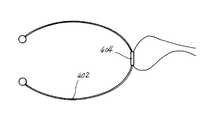
세 번째로는 환자의 흉부와 등의 반 정도를 감싸듯 장착되고 탄력과 신축성이 있는 플라스틱 또는 강철밴드(402)에 접착된 장력 저항이 환자의 호흡동작에 의하여 변화하는 전기저항의 변화에 의하여 작동하는 센서 부재(404)를 구비하는 것이다.Thirdly, the tension resistance, which is attached to the patient's chest and back, is attached to the elastic and elastic plastic or
또한 상기 전자식 고통 완화 장치는 피드백 루프(116), 수동 입력버튼(120)과 LCD 모니터(122), 및 전원 공급부(130)를 구비한다. 또한 출력 증폭부(114a, 114b)의 출력단에는 복수개의 자극 전극(142a, 142b, 142c)을 구비한다.In addition, the electronic pain relief device includes a
상기와 같이 이루어진 본 발명의 전자식 고통 완화 장치의 동작을 설명한다.It describes the operation of the electronic pain relief device of the present invention made as described above.
호흡 센서(102)는 환자의 호흡을 느낄 수 있는 부위에 부착되어 호흡을 감지하여 호흡 신호를 공급하고, A/D 변환부(104)는 아날로그 형식의 호흡 신호를 디지털 신호로 변환하여 마이크로프로세서(110)로 공급한다. 이로써, 호흡센서(102)로부터 출력된 호흡 신호는 환자의 호흡률에 의하여 연동되는 두 개의 출력 증폭부(114a, 114b)의 입력 파라메타를 변조하기 위하여 A/D 변환부(104)를 통해 마이크로프로세서(110)로 입력된다.The
마이크로프로세서(104)는 A/D 변환부(104)를 통하여 호흡 센서(102)에 접속되어 출력된 호흡 신호를 사용하여 호흡률을 구하고 구한 호흡률을 기초로 상기 자극 전극에 공급되는 자극 전류를 규칙화하여 선택적으로 임펄스 또는 시누쏘이달 전류를 생성한다. 자극의 밀도는 환자의 상황을 고려하여 설정하며, 환자는 치료 파라메타를 컨트롤할 수 있다. 증폭이나 전류의 주파수는 환자 자신의 호흡률에 의하여 자동으로 규칙화되기 때문이다. 이것을 쉽게 하기 위하여 환자의 호흡률이 매우 빠르게 작동되는 변환바에 의하여 LCD 화면 위에서 지정되도록 한다. 즉, LCD 모니터(122)와 수동 입력 버튼(120)은 기기의 셋업과 자극 파라메타의 컨트롤을 위하여 사용된다.The
상기와 같이 본 발명에 따른 호흡 피드백 컨트롤을 사용한 전자식 고통 완화 장치는 환자의 신체 리듬, 특히 호흡률로부터 얻어진 피드백 신호에 의하여 전기 자극 전류를 컨트롤할 수 있는 독특한 방법에 기초한다. 이 방법의 효율을 극대화하기 위하여 이하에서 설명되는 바와 같이 증폭부와 호흡률에 의하여 자극되는 주파수 변조를 쓰고 있다. 이러한 접근 방법은 신체조직 리듬과 외부로부터 가해지는 규칙적인 전기 자극에 의한 상호 공명 작용에 기초한다.As described above, the electronic pain relief device using the respiration feedback control according to the present invention is based on a unique method of controlling the electrical stimulation current by the feedback signal obtained from the body rhythm of the patient, especially the respiration rate. In order to maximize the efficiency of this method, as described below, the frequency modulation stimulated by the amplification unit and the respiration rate is used. This approach is based on the mutual resonance action by the body rhythm and regular electrical stimulation from the outside.
다음으로, 출력 증폭부(114a, 114b)는 임펄스 또는 시누쏘이달 전류를 증폭하여 자극 전류를 출력한다. 자극 전극(142a, 142b, 142c)은 환자의 아픈 부위에 부착되어 아픈 부위의 고통을 완화하기 위한 임펄스 또는 시누쏘이달 자극 전류를 공급한다. D/A변환부(112a, 112b, 112c : 임펄스 모드에서 동작) 또는 싸인파 발생부(113a, 113b : G1,G2 : 시누쏘이달 모드에서 동작)를 통하여 발생된 신호들은 출력 증폭부(114a, 114b)를 통과하여 자극 전극(142a, 142b, 142c : e1, e2, e3)으로 들어간다. 시누쏘이달 모드의 변조에서는 자극이 깊은 근육조직과 신경섬유에 도달한다, 본 발명에 따른 고통 완화 장치는 이와 같이 임펄스 모드와 시누쏘이달 모드의 복합적인 기능을 수행한다는 것에 주목하여야 할 것이다.Next, the output amplifiers 114a and 114b amplify an impulse or sinusoidal current to output a stimulus current. The
피드백 루프(116)는 입력단이 출력 증폭부(114b)의 출력단에 접속되고 출력단은 마이크로프로세서(110)의 입력단에 접속되는 A/D 변환부(116b, 116c)로 이루어진다. 피드백 루프(116)는 상기 자극 전극에 공급되는 값을 상기 마이크로프로세서로 피드백한다. 마이크로프로세서(110)에 연결된 A/D 변환부(116b, 116c)를 통한 출력 증폭부(114b)의 출력으로 부터 얻어지는 피드백 루프(116) 시누쏘이달 모드는 컨트롤과 출력 전류를 통제하는데 사용된다.The
D/A 변환부(112a, 112b, 112c)는 마이크로프로세서(110)로 부터 출력되어 규칙화된 자극 전류를 나타내는 디지털 데이터를 임펄스 신호 형태의 아날로그 신호로 변환하고, 출력 증폭부(114a, 114b)는 D/A 변환부(112a, 112b, 112c)로부터 출력되어 규칙화된 자극 전류를 나타내는 임펄스 신호 형태의 아날로그 신호를 증폭한다.The D / A converters 112a, 112b, and 112c convert the digital data representing the regular stimulus current output from the
상기 마이크로프로세서(110)는 환자의 호흡률에 의하여 연동되는 임펄스 또는 시누쏘이달 모드 전류의 증폭을 변환시킬 수 있도록 제어하는 증폭 변조모드 및 환자의 호흡률에 의하여 연동되는 임펄스 또는 시누쏘이달 모드 전류의 주파수를 바꿀 수 있도록 제어하는 주파수 변조모드를 선택적으로 제어한다.The
싸인파 발생부(113a, 113b)는 시누쏘이달 모드에서 환자의 호흡률에 의하여 연동되는 전류에 해당하는 싸인파를 발생하고, 출력 증폭부(114b)는 싸인파 발생부(113a, 113b)로 부터 출력되어 규칙화된 자극 전류를 나타내는 싸인파 형태의 아날로그 신호를 증폭한다. 전원 공급부(130)는 DC 9 볼트의 전원 전압을 공급한다.The sine wave generators 113a and 113b generate a sine wave corresponding to a current interlocked by the respiratory rate of the patient in the sinusoidal mode, and the output amplifying unit 114b from the sine wave generators 113a and 113b. It outputs and amplifies an analog signal in the form of a sine wave representing a regular stimulus current. The
도 3 에는 도 1 의 장치를 사용하는 과정을 흐름도로 나타내었다. 도 3 을 참조하면, 자극 전극을 환자의 아픈 부위에 부착(S202)하고, 호흡 센서를 환자의 코, 손목, 또는 가슴에 부착(S204)한다. 다음으로, 마이크로프로세서는 사용자의 조작으로 수동 입력 버튼 및 LCD 화면을 통하여 임펄스 또는 시누쏘이달의 자극 모드를 선택(S206)하여 디지털 신호를 발생시킨다. 또한, 증폭 변조를 할 것인지 주파수 변조를 할 것인지에 대한 전류 변조 모드를 선택(S208)한다. 이제, 호흡 센서를 통하여 호흡률을 구한다(S210). 호흡률을 사용하여 자극 전극에 공급될 자극 전류를 규칙화(S212)하고, 규칙화된 자극 전류를 사용하여 환자의 아픈부위에 자극(S214)함으로써 고통 완화 프로세스가 수행된다.3 shows a flow chart of the process of using the apparatus of FIG. Referring to FIG. 3, the stimulation electrode is attached to the painful part of the patient (S202), and the breathing sensor is attached to the nose, wrist, or chest of the patient (S204). Next, the microprocessor selects the stimulus mode of the impulse or the sinusoidal through the manual input button and the LCD screen by the user's operation (S206) to generate the digital signal. In addition, the current modulation mode for amplification modulation or frequency modulation is selected (S208). Now, the breathing rate is obtained through the breathing sensor (S210). The pain relief process is performed by regularizing the stimulation current to be supplied to the stimulation electrode using the respiratory rate (S212), and by stimulating (S214) the sick area of the patient using the regulated stimulation current.
상기와 같은 본 발명에 따른 고통 완화 장치는 종래의 일반적인 TENS 기기와 비교하여 치료 속도나 고통 완화 지속 시간 등이 현저하게 증가되고, 고통 완화와 동시에 호흡 피드백에 의하여 컨트롤된 자극은 환자의 신체 상태를 양호한 상태로 변환시키는 원인으로도 작용하여 예를 들면 심혈관 질환 환자들은 두통 감소와 함께, 현저한 혈압의 안정화를 이룰 수 있다.Pain relief device according to the present invention as described above is significantly increased compared to the conventional general TENS device, the treatment speed, pain relief duration, etc., and the stimulation controlled by the respiration feedback at the same time pain relief and the patient's physical condition It also acts as a cause for conversion to good condition, for example, patients with cardiovascular disease can achieve significant blood pressure stabilization with headache reduction.
또한, 상기와 같은 호흡 피드백 컨트롤을 사용한 전자식 고통 완화 장치는 호흡률에 의하여 통제되는 전류를 이용하여 20 ~ 30 분씩 반복하여 실험한 결과, 내성에 대한 징후는 전혀 나타나지 않았다. 즉, 본 발명에 따른 호흡 피드백 컨트롤을 사용한 전자식 고통 완화 장치는 자극에 대한 내성이 생기지 않도록 하고 뇌 의 구조적 자극을 강화시키기 위한 방법인 것이다.In addition, the electronic pain relief device using the breathing feedback control as described above repeated 20 to 30 minutes using a current controlled by the respiratory rate, there was no sign of resistance at all. That is, the electronic pain relief device using the respiration feedback control according to the present invention is a method for preventing the resistance to stimulation and strengthening the structural stimulation of the brain.
상술한 바와 같이 본 발명에 따른 호흡 피드백 컨트롤을 사용한 전자식 고통 완화 장치는,As described above, the electronic pain relief device using the respiration feedback control according to the present invention,
종래의 일반적인 TENS 기기와 비교하여 치료 속도나 고통 완화 지속 시간 등이 현저하게 증가되고, 고통 완화와 동시에 호흡 피드백에 의하여 컨트롤된 자극은 환자의 신체 상태를 양호한 상태로 변환시키는 원인으로도 작용하여 예를 들면 심혈관 질환 환자들은 두통 감소와 함께 현저한 혈압의 안정화를 이룰 수 있다.
Compared with conventional TENS devices, treatment speed and pain relief duration are significantly increased, and pain relief and stimulation controlled by respiration feedback also act as a cause of changing the patient's physical condition to a good state. For example, patients with cardiovascular disease can achieve significant blood pressure stabilization with headache reduction.
Claims (5)
Translated fromKoreanPriority Applications (1)
| Application Number | Priority Date | Filing Date | Title |
|---|---|---|---|
| KR1020040032991AKR100743354B1 (en) | 2004-05-11 | 2004-05-11 | Electronic Pain Relief with Breathing Feedback Control |
Applications Claiming Priority (1)
| Application Number | Priority Date | Filing Date | Title |
|---|---|---|---|
| KR1020040032991AKR100743354B1 (en) | 2004-05-11 | 2004-05-11 | Electronic Pain Relief with Breathing Feedback Control |
Publications (2)
| Publication Number | Publication Date |
|---|---|
| KR20050108445A KR20050108445A (en) | 2005-11-16 |
| KR100743354B1true KR100743354B1 (en) | 2007-07-26 |
Family
ID=37284531
Family Applications (1)
| Application Number | Title | Priority Date | Filing Date |
|---|---|---|---|
| KR1020040032991AExpired - Fee RelatedKR100743354B1 (en) | 2004-05-11 | 2004-05-11 | Electronic Pain Relief with Breathing Feedback Control |
Country Status (1)
| Country | Link |
|---|---|
| KR (1) | KR100743354B1 (en) |
Cited By (2)
| Publication number | Priority date | Publication date | Assignee | Title |
|---|---|---|---|---|
| KR101263581B1 (en)* | 2011-08-11 | 2013-05-13 | 경희대학교 산학협력단 | Apparatus for stimulating human body using real-time feedback controlloop |
| US10881854B2 (en) | 2016-10-28 | 2021-01-05 | Research Cooperation Foundation Of Yeungnam University | Respiratory muscle strengthening device |
Citations (1)
| Publication number | Priority date | Publication date | Assignee | Title |
|---|---|---|---|---|
| JPH06327693A (en)* | 1993-05-07 | 1994-11-29 | Siemens Ag | Pain relief device |
- 2004
- 2004-05-11KRKR1020040032991Apatent/KR100743354B1/ennot_activeExpired - Fee Related
Patent Citations (1)
| Publication number | Priority date | Publication date | Assignee | Title |
|---|---|---|---|---|
| JPH06327693A (en)* | 1993-05-07 | 1994-11-29 | Siemens Ag | Pain relief device |
Cited By (2)
| Publication number | Priority date | Publication date | Assignee | Title |
|---|---|---|---|---|
| KR101263581B1 (en)* | 2011-08-11 | 2013-05-13 | 경희대학교 산학협력단 | Apparatus for stimulating human body using real-time feedback controlloop |
| US10881854B2 (en) | 2016-10-28 | 2021-01-05 | Research Cooperation Foundation Of Yeungnam University | Respiratory muscle strengthening device |
Also Published As
| Publication number | Publication date |
|---|---|
| KR20050108445A (en) | 2005-11-16 |
Similar Documents
| Publication | Publication Date | Title |
|---|---|---|
| RU2445749C2 (en) | Audiologic transmission system | |
| ES2908418T3 (en) | Atrial neurostimulation device and system | |
| JP5512664B2 (en) | Ear stimulator for creating stimulus signals for ears | |
| CN101107040B (en) | Device for the transdermal stimulation of a nerve of the human body | |
| ES2817832T3 (en) | Device for auditory stimulation | |
| CN101678206B (en) | Single-point stimulation device | |
| US20110166624A1 (en) | Device for the transdermal stimulation of a nerve of the human body | |
| US20100204614A1 (en) | Electronic snore recording device and associated methods | |
| EP1311320A4 (en) | Electrostimulation system with electromyographic and visual biofeedback | |
| EP0938911A3 (en) | Electrical apparatus for medical treatment using EMG envelope signal | |
| EP3914203B1 (en) | Devices for treating obstructive sleep apnea | |
| KR102222694B1 (en) | Wearable oral system and method of adjusting position of soft-palate and tongue | |
| EP2944351B1 (en) | Respiratory abnormality improvement apparatus | |
| JPWO2021099466A5 (en) | ||
| KR100743354B1 (en) | Electronic Pain Relief with Breathing Feedback Control | |
| KR102071060B1 (en) | Palatal implant and electronical stimulation system using thereof | |
| US20080091111A1 (en) | Sphygmomanometer Of Multi Functional | |
| JP2014028052A (en) | External pacemaker | |
| TWI296103B (en) | ||
| JP3087449U (en) | Low frequency treatment device | |
| KR102766703B1 (en) | Method and device of tactile stimulation using air pressure to activate parasympathetic activity | |
| KR100578397B1 (en) | Beauty treatment device using electric signal of music | |
| JPH08299463A (en) | Low frequency medical treatment apparatus | |
| EP4093486A1 (en) | Electrode structure | |
| CN119896813A (en) | Electrical stimulation assisted breathing device and method |
Legal Events
| Date | Code | Title | Description |
|---|---|---|---|
| A201 | Request for examination | ||
| PA0109 | Patent application | St.27 status event code:A-0-1-A10-A12-nap-PA0109 | |
| PA0201 | Request for examination | St.27 status event code:A-1-2-D10-D11-exm-PA0201 | |
| PN2301 | Change of applicant | St.27 status event code:A-3-3-R10-R13-asn-PN2301 St.27 status event code:A-3-3-R10-R11-asn-PN2301 | |
| R17-X000 | Change to representative recorded | St.27 status event code:A-3-3-R10-R17-oth-X000 | |
| D13-X000 | Search requested | St.27 status event code:A-1-2-D10-D13-srh-X000 | |
| D14-X000 | Search report completed | St.27 status event code:A-1-2-D10-D14-srh-X000 | |
| PG1501 | Laying open of application | St.27 status event code:A-1-1-Q10-Q12-nap-PG1501 | |
| E902 | Notification of reason for refusal | ||
| PE0902 | Notice of grounds for rejection | St.27 status event code:A-1-2-D10-D21-exm-PE0902 | |
| T11-X000 | Administrative time limit extension requested | St.27 status event code:U-3-3-T10-T11-oth-X000 | |
| R17-X000 | Change to representative recorded | St.27 status event code:A-3-3-R10-R17-oth-X000 | |
| T12-X000 | Administrative time limit extension not granted | St.27 status event code:U-3-3-T10-T12-oth-X000 | |
| E601 | Decision to refuse application | ||
| PE0601 | Decision on rejection of patent | St.27 status event code:N-2-6-B10-B15-exm-PE0601 | |
| J201 | Request for trial against refusal decision | ||
| PJ0201 | Trial against decision of rejection | St.27 status event code:A-3-3-V10-V11-apl-PJ0201 | |
| J301 | Trial decision | Free format text:TRIAL DECISION FOR APPEAL AGAINST DECISION TO DECLINE REFUSAL REQUESTED 20060728 Effective date:20070627 | |
| PJ1301 | Trial decision | St.27 status event code:A-3-3-V10-V15-crt-PJ1301 Decision date:20070627 Appeal event data comment text:Appeal Kind Category : Appeal against decision to decline refusal, Appeal Ground Text : 2004 0032991 Appeal request date:20060728 Appellate body name:Patent Examination Board Decision authority category:Office appeal board Decision identifier:2006101006662 | |
| PS0901 | Examination by remand of revocation | St.27 status event code:A-6-3-E10-E12-rex-PS0901 | |
| S901 | Examination by remand of revocation | ||
| GRNO | Decision to grant (after opposition) | ||
| PS0701 | Decision of registration after remand of revocation | St.27 status event code:A-3-4-F10-F13-rex-PS0701 | |
| GRNT | Written decision to grant | ||
| PR0701 | Registration of establishment | St.27 status event code:A-2-4-F10-F11-exm-PR0701 | |
| PR1002 | Payment of registration fee | St.27 status event code:A-2-2-U10-U11-oth-PR1002 Fee payment year number:1 | |
| PG1601 | Publication of registration | St.27 status event code:A-4-4-Q10-Q13-nap-PG1601 | |
| PR1001 | Payment of annual fee | St.27 status event code:A-4-4-U10-U11-oth-PR1001 Fee payment year number:4 | |
| PR1001 | Payment of annual fee | St.27 status event code:A-4-4-U10-U11-oth-PR1001 Fee payment year number:5 | |
| PN2301 | Change of applicant | St.27 status event code:A-5-5-R10-R13-asn-PN2301 St.27 status event code:A-5-5-R10-R11-asn-PN2301 | |
| PR1001 | Payment of annual fee | St.27 status event code:A-4-4-U10-U11-oth-PR1001 Fee payment year number:6 | |
| PN2301 | Change of applicant | St.27 status event code:A-5-5-R10-R13-asn-PN2301 St.27 status event code:A-5-5-R10-R11-asn-PN2301 | |
| FPAY | Annual fee payment | Payment date:20130529 Year of fee payment:7 | |
| PR1001 | Payment of annual fee | St.27 status event code:A-4-4-U10-U11-oth-PR1001 Fee payment year number:7 | |
| FPAY | Annual fee payment | Payment date:20140709 Year of fee payment:8 | |
| PR1001 | Payment of annual fee | St.27 status event code:A-4-4-U10-U11-oth-PR1001 Fee payment year number:8 | |
| FPAY | Annual fee payment | Payment date:20150706 Year of fee payment:9 | |
| PR1001 | Payment of annual fee | St.27 status event code:A-4-4-U10-U11-oth-PR1001 Fee payment year number:9 | |
| PN2301 | Change of applicant | St.27 status event code:A-5-5-R10-R13-asn-PN2301 St.27 status event code:A-5-5-R10-R11-asn-PN2301 | |
| FPAY | Annual fee payment | Payment date:20160719 Year of fee payment:10 | |
| PR1001 | Payment of annual fee | St.27 status event code:A-4-4-U10-U11-oth-PR1001 Fee payment year number:10 | |
| P22-X000 | Classification modified | St.27 status event code:A-4-4-P10-P22-nap-X000 | |
| FPAY | Annual fee payment | Payment date:20170719 Year of fee payment:11 | |
| PR1001 | Payment of annual fee | St.27 status event code:A-4-4-U10-U11-oth-PR1001 Fee payment year number:11 | |
| FPAY | Annual fee payment | Payment date:20180704 Year of fee payment:12 | |
| PR1001 | Payment of annual fee | St.27 status event code:A-4-4-U10-U11-oth-PR1001 Fee payment year number:12 | |
| PC1903 | Unpaid annual fee | St.27 status event code:A-4-4-U10-U13-oth-PC1903 Not in force date:20190721 Payment event data comment text:Termination Category : DEFAULT_OF_REGISTRATION_FEE | |
| R18-X000 | Changes to party contact information recorded | St.27 status event code:A-5-5-R10-R18-oth-X000 | |
| PC1903 | Unpaid annual fee | St.27 status event code:N-4-6-H10-H13-oth-PC1903 Ip right cessation event data comment text:Termination Category : DEFAULT_OF_REGISTRATION_FEE Not in force date:20190721 |