KR100742541B1 - Magnetic resonance energy device - Google Patents
Magnetic resonance energy deviceDownload PDFInfo
- Publication number
- KR100742541B1 KR100742541B1KR1020070031117AKR20070031117AKR100742541B1KR 100742541 B1KR100742541 B1KR 100742541B1KR 1020070031117 AKR1020070031117 AKR 1020070031117AKR 20070031117 AKR20070031117 AKR 20070031117AKR 100742541 B1KR100742541 B1KR 100742541B1
- Authority
- KR
- South Korea
- Prior art keywords
- water
- case
- magnetic resonance
- water supply
- resonance energy
- Prior art date
- Legal status (The legal status is an assumption and is not a legal conclusion. Google has not performed a legal analysis and makes no representation as to the accuracy of the status listed.)
- Expired - Fee Related
Links
Images


Classifications
- C—CHEMISTRY; METALLURGY
- C02—TREATMENT OF WATER, WASTE WATER, SEWAGE, OR SLUDGE
- C02F—TREATMENT OF WATER, WASTE WATER, SEWAGE, OR SLUDGE
- C02F1/00—Treatment of water, waste water, or sewage
- C02F1/48—Treatment of water, waste water, or sewage with magnetic or electric fields
- C02F1/487—Treatment of water, waste water, or sewage with magnetic or electric fields using high frequency electromagnetic fields, e.g. pulsed electromagnetic fields
- C—CHEMISTRY; METALLURGY
- C02—TREATMENT OF WATER, WASTE WATER, SEWAGE, OR SLUDGE
- C02F—TREATMENT OF WATER, WASTE WATER, SEWAGE, OR SLUDGE
- C02F1/00—Treatment of water, waste water, or sewage
- C02F1/48—Treatment of water, waste water, or sewage with magnetic or electric fields
- C02F1/481—Treatment of water, waste water, or sewage with magnetic or electric fields using permanent magnets
- C—CHEMISTRY; METALLURGY
- C02—TREATMENT OF WATER, WASTE WATER, SEWAGE, OR SLUDGE
- C02F—TREATMENT OF WATER, WASTE WATER, SEWAGE, OR SLUDGE
- C02F2201/00—Apparatus for treatment of water, waste water or sewage
- C02F2201/48—Devices for applying magnetic or electric fields
- C—CHEMISTRY; METALLURGY
- C02—TREATMENT OF WATER, WASTE WATER, SEWAGE, OR SLUDGE
- C02F—TREATMENT OF WATER, WASTE WATER, SEWAGE, OR SLUDGE
- C02F2307/00—Location of water treatment or water treatment device
- C02F2307/10—Location of water treatment or water treatment device as part of a potable water dispenser, e.g. for use in homes or offices
Landscapes
- Life Sciences & Earth Sciences (AREA)
- Hydrology & Water Resources (AREA)
- Engineering & Computer Science (AREA)
- Environmental & Geological Engineering (AREA)
- Water Supply & Treatment (AREA)
- Chemical & Material Sciences (AREA)
- Organic Chemistry (AREA)
- Physics & Mathematics (AREA)
- Electromagnetism (AREA)
- Water Treatment By Electricity Or Magnetism (AREA)
Abstract
Translated fromKoreanDescription
Translated fromKorean도 1은 본 발명에 따른 자기 공명 에너지 장치의 구성을 나타낸 분해 사시도,1 is an exploded perspective view showing the configuration of a magnetic resonance energy device according to the present invention,
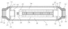
도 2는 본 발명에 따른 자기 공명 에너지 장치의 구성을 나타낸 사시도,2 is a perspective view showing the configuration of a magnetic resonance energy device according to the present invention;
도 3은 도 2의 A-A 단면도,3 is a cross-sectional view taken along line A-A of FIG.
도 4는 본 발명의 다른 실시예에 따른 자기 공명 에너지 장치의 구성을 나타낸 사시도,4 is a perspective view showing the configuration of a magnetic resonance energy device according to another embodiment of the present invention;
도 5는 도 4의 B-B 단면도,5 is a cross-sectional view taken along line B-B of FIG. 4;
도 6은 본 발명에 따른 자기 공명 에너지 장치의 자장 형성 모양을 설명한 도면.6 is a view for explaining the magnetic field forming shape of the magnetic resonance energy device according to the present invention.
<도면의 주요 부분에 관한 부호의 설명><Explanation of symbols on main parts of the drawings>
110 : 케이스120 : 제 1캡110: case 120: first cap
130 : 제 2캡140 : 물 공급 클램프130: second cap 140: water supply clamp
150 : 물 배출 클램프160 : 지지봉150: water discharge clamp 160: support rod
170 : 영구자석180 : 정수기 캡170: permanent magnet 180: water purifier cap
190 : 물 유동로190: water flow path
본 발명은 자기 공명 에너지 장치에 관한 것으로서, 상세하게는 일렬로 배열된 영구자석과 물을 직접 접촉시키도록 하는 자기 공명 에너지 장치에 관한 것이다.The present invention relates to a magnetic resonance energy device, and more particularly, to a magnetic resonance energy device for directly contacting water with a permanent magnet arranged in a line.
일반적으로, 물은 2개의 수소원자와 1개의 산소원자가 결합된 것으로, 온도가 높아질수록 5개로 구성된 사슬모양 또는 5각형의 고리모양을 이루고, 온도가 내려갈수록 6각형 고리모양의 분자구조를 가지는 육각수가 생성된다.In general, water is a combination of two hydrogen atoms and one oxygen atom, and as the temperature increases, a hexagonal ring having a hexagonal ring-shaped molecular structure is formed as the chain consists of five chains or a pentagonal shape. Is generated.
따라서, 육각수는 물을 냉각시켜 온도를 저하시키면 생성할 수 있으며, 생성된 육각수는 열용량이 크고 다른 생체분자들과 잘 어울려 생물체의 생명기능을 향상시키는 것으로 알려져 있다.Therefore, hexagonal water can be produced by cooling the water to lower the temperature, and the generated hexagonal water has a large heat capacity and is known to improve the life function of living organisms by becoming well matched with other biomolecules.
그런데, 물을 냉각시켜 육각수를 생성하는 방법은 에너지 손실이 크며, 생성효과가 미흡하여 사용되지 않는 바, 근래에는 물을 자석의 자장속으로 통과시키면서 물의 분자구조를 이온 활성화시켜 미네랄이 풍부한 약알칼리성의 6각형 구조를 가지는 자화 육각수가 생성되게 하는 제조장치가 사용되고 있다.However, the method of generating hexagonal water by cooling the water has a large energy loss and it is not used due to its insufficient effect. In recent years, water is passed through the magnetic field of the magnet and ion-activates the molecular structure of the water, which is rich in minerals. The manufacturing apparatus which produces | generates the magnetized hexagonal water which has the hexagonal structure of is used.
자화 육각수는 물이 강력한 자장속을 수직으로 통과할 때, 물속의 분자구조가 6각형으로 세분화되어 인체의 세포 조직이 가장 좋아하는 성분을 함유하게 되는 물을 말한다. 물에 게르마늄 이온을 첨가하거나 물을 아주 차가운 상태로 만들어 얻어질 수 있다고 하는데, 뇌졸중 당뇨병 등의 각종 성인병을 예방하는 데 도움을 주고 인체의 면역력을 높여 주는 것으로 알려져 있다.Magnetized hexagonal water refers to water whose molecular structure in the water is broken down into hexagons when water passes vertically through a strong magnetic field, and contains the most favorite components of human tissue. It can be obtained by adding germanium ions to water or making the water very cold. It is known to help prevent various adult diseases such as stroke diabetes and increase the body's immunity.
이와같은 자화 육각수를 처리하기 위한 종래의 자화 육각수 생성장치는 국내등록특허 제521075호 및 등록실용신안 제336218호에 게재된 바와 같이, 물이 흐르는 배관의 상하에 영구자석을 각각 배치하되, 물이 흐르는 방향의 직각방향으로 자장을 형성하도록 한 쌍의 영구자석은 그 대향면이 N극과 S극으로 배치하였다.Conventional magnetization hexagonal water generating apparatus for treating such magnetized hexagonal water, as published in Korean Patent No. 521075 and Utility Model No. 336218, the permanent magnets are arranged above and below the water flowing pipe, respectively, The pair of permanent magnets were arranged at the north and south poles so that their opposite surfaces formed a magnetic field in a direction perpendicular to the flowing direction.
이와 같이 물이 흐르는 방향에 대하여 직각방향으로 자장을 형성하면 물의 표면장력이 커지게 되고, 이에 따라 물의 분자구조가 이온 활성화되면서 물은 미네랄이 풍부한 약알카리성의 6각형의 구조수(육각수)인 자화 육각수를 생성하였다.As such, when the magnetic field is formed in a direction perpendicular to the direction of water flow, the surface tension of the water increases. Accordingly, as the molecular structure of the water is ion-activated, the water is magnetized as a weakly alkaline hexagonal structure water (hexagonal number) rich in minerals. Hexagonal water was generated.
그러나, 이와 같은 종래의 자화 육각수 생성장치들은 영구자석과 물의 사이에 알루미늄과 같은 케이스가 위치하기 때문에 영구자석의 자장이 케이스에 의해 감쇄되어 실제 자화 육각수를 생성하는 효율이 상대적으로 낮아지고, 자화 육각수 자체가 갖는 파장의 세기가 약하여 효능이 저하되는 문제점이 있다.However, in the conventional magnetization hexagonal water generators, since a case such as aluminum is located between the permanent magnet and water, the magnetic field of the permanent magnet is attenuated by the case, and the efficiency of generating the actual magnetization hexagonal water is relatively low. There is a problem in that the efficacy is lowered because the intensity of the wavelength itself is weak.
본 발명은 상기와 같은 문제점을 해결하기 위한 것으로, 일렬로 배열된 영구자석과 물을 직접 접촉시킴으로써 자장이 감쇄되는 것을 방지하여 자화 육각수를 생성 효율을 상대적으로 높이고, 자화 육각수 자체가 갖는 파장의 세기가 높여 효능을 증대시키도록 하는 자기 공명 에너지 장치를 제공하는데 그 목적이 있다.The present invention is to solve the above problems, by directly contacting the permanent magnets arranged in a row and water to prevent the magnetic field is attenuated to increase the efficiency of generating a magnetized hexagonal water, the intensity of the wavelength of the magnetized hexagonal water itself It is an object of the present invention to provide a magnetic resonance energy device to increase the efficiency to increase.
상기와 같은 목적을 달성하기 위한 본 발명의 특징은,Features of the present invention for achieving the above object,
양단이 개방된 원통형으로 형성되고, 양단 내측에 제 1, 2결합홈이 형성되는 케이스와; 원형으로 형성되되, 이를 관통하도록 제 1물 공급홀이 형성되고, 상기 케이스의 제 1결합홈에 결합되도록 일측면에 제 1단턱이 형성되는 제 1캡과; 원형으로 형성되되, 이를 관통하도록 제 1물 배출홀이 형성되고, 상기 케이스의 제 2결합홈에 결합되도록 타측면에 제 2단턱이 형성되는 제 2캡과; 일측면이 개방된 원통형으로 형성되되, 상기 케이스의 제 1결합홈에 안착되도록 개방된 일측면 끝단에서 수직으로 제 1날개판이 형성되고, 타측면 중앙부에 볼트홀이 형성되는 물 공급 클램프와; 타측면이 개방된 원통형으로 형성되되, 상기 케이스의 제 2결합홈에 안착되도록 개방된 타측면 끝단에서 수직으로 제 2날개판이 형성되는 물 배출 클램프와; 상기 물 공급 클램프의 볼트홀에 일단이 결합되고, 타단에 너트가 결합되어 상기 케이스의 중앙부에 위치하는 지지봉; 및 원판형태로 형성되되, 중앙부에 상기 지지봉에 삽입되도록 삽입홀이 형성되어 상기 지지봉에 순차적으로 적층되는 복수의 영구자석을 포함하는 것을 특징으로 한다.A case in which both ends are formed in an open cylindrical shape, and first and second coupling grooves are formed inside both ends; A first cap which is formed in a circular shape, a first water supply hole is formed to penetrate the first water supply hole, and a first stepped portion is formed on one side to be coupled to the first coupling groove of the case; A second cap which is formed in a circular shape, a first water discharge hole is formed to penetrate it, and a second stepped jaw is formed on the other side to be coupled to the second coupling groove of the case; A water supply clamp having one side formed in an open cylindrical shape, the first wing plate being vertically formed at one end of the side open to be seated in the first coupling groove of the case, and a bolt hole formed at the center of the other side; A water discharge clamp having a second side plate formed in an open cylindrical shape, the second wing plate being vertically formed at an end of the other side open to be seated in the second coupling groove of the case; A support rod having one end coupled to the bolt hole of the water supply clamp and a nut coupled to the other end, the support rod being located at the center of the case; And it is formed in the shape of a disk, the insertion hole is formed so as to be inserted into the support rod in the center is characterized in that it comprises a plurality of permanent magnets sequentially stacked on the support rod.
여기에서, 상기 물 공급 클램프는 측면에 서로 대응되는 제 2물 공급홀이 각각 형성되고, 상기 물 배출 클램프는 측면에 서로 대응되는 제 2물 배출홀이 각각 형성된다.Here, each of the water supply clamps may have second water supply holes corresponding to each other, and the water discharge clamps may have second water discharge holes corresponding to each other.
여기에서 또한, 상기 영구자석은 척력이 발생하도록 동일 극성이 대향되도록 배치되며, 순차적으로 동일 극성이 대향되도록 배치되다가 그 배열중 중앙에 위치한 영구자석을 기준으로 그 극성이 뒤바뀐 다음 동일 극성이 대향되도록 배치된다.Here, the permanent magnets are arranged so that the same polarity is opposite to each other so that repulsion is generated, and the same polarities are sequentially arranged to face each other, and then the polarities thereof are reversed based on the permanent magnet located at the center of the arrangement, and then the same polarity is opposite. Is placed.
여기에서 또, 상기 영구자석의 외측면과 상기 케이스의 내주면은 10~20㎜의 간격으로 이격되어 물 유동로를 형성한다.Here, the outer surface of the permanent magnet and the inner circumferential surface of the case are spaced apart at intervals of 10 to 20 mm to form a water flow path.
여기에서 또, 상기 제 1캡의 제 1물 공급홀 및 제 2캡의 제 1물 배출홀은 그 내주면에 나사산이 형성되고, 상기 나사산에는 정수기에 결합이 가능하도록 정수기 캡이 탈부착된다.Here, the first water supply hole of the first cap and the first water discharge hole of the second cap have a thread formed on an inner circumferential surface thereof, and the water purifier cap is detachably attached to the screw so as to be coupled to a water purifier.
이하, 본 발명에 따른 자기 공명 에너지 장치의 구성을 첨부된 도면을 참조하여 상세하게 설명하면 다음과 같다.Hereinafter, the configuration of the magnetic resonance energy device according to the present invention will be described in detail with reference to the accompanying drawings.
하기에서 본 발명을 설명함에 있어, 관련된 공지 기능 또는 구성에 대한 구체적인 설명이 본 발명의 요지를 불필요하게 흐릴 수 있다고 판단되는 경우에는 그 상세한 설명은 생략할 것이다. 그리고 후술되는 용어들은 본 발명에서의 기능을 고려하여 정의된 용어들로서 이는 사용자, 운용자의 의도 또는 관례 등에 따라 달라질 수 있다. 그러므로 그 정의는 본 명세서 전반에 걸친 내용을 토대로 내려져야 할 것이다.In the following description of the present invention, if it is determined that a detailed description of a related known function or configuration may unnecessarily obscure the subject matter of the present invention, the detailed description thereof will be omitted. Terms to be described later are terms defined in consideration of functions in the present invention, and may be changed according to intentions or customs of users or operators. Therefore, the definition should be made based on the contents throughout the specification.
도 1은 본 발명에 따른 자기 공명 에너지 장치의 구성을 나타낸 분해 사시도이고, 도 2는 본 발명에 따른 자기 공명 에너지 장치의 구성을 나타낸 사시도이며, 도 3은 도 2의 A-A 단면도이고, 도 4는 본 발명의 다른 실시예에 따른 자기 공명 에너지 장치의 구성을 나타낸 사시도이며, 도 5는 도 4의 B-B 단면도이다.1 is an exploded perspective view showing the configuration of a magnetic resonance energy device according to the present invention, Figure 2 is a perspective view showing the configuration of a magnetic resonance energy device according to the present invention, Figure 3 is a cross-sectional view AA of Figure 2, Figure 4 4 is a perspective view showing the configuration of a magnetic resonance energy device according to another embodiment of the present invention, and FIG. 5 is a sectional view taken along line BB of FIG.
도 1 내지 도 5를 참조하면, 본 발명에 따른 자기 공명 에너지 장치(100)는, 케이스(110)와, 제 1캡(120)과, 제 2캡(130)과, 물 공급 클램프(140)와, 물 배출 클램프(150)와, 지지봉(160)과, 영구자석(170) 및 정수기 캡(180)으로 구성된다.1 to 5, the magnetic resonance energy device 100 according to the present invention includes a
먼저, 케이스(110)는 알루미늄과 같은 금속 재질로 양단이 개방된 원통형으로 형성되고, 양단 내측에 제 1, 2결합홈(111, 113)이 형성된다. 여기에서, 도 3의 도면상 우측에 위치한 것이 제 1결합홈(111)이고, 도 3의 도면상 좌측에 위치한 것이 제 2결합홈(113)이다.First, the
그리고, 제 1캡(120)은 케이스(110)와 동일 재질로 원형으로 형성되되, 이를 관통하도록 제 1물 공급홀(121)이 형성되고, 케이스(110)의 제 1결합홈(111)에 결합되도록 일측면에 제 1단턱(123)이 형성된다. 여기에서, 제 1캡(120)은 일측이 좁고 타측으로 갈수록 넓어지는 형태로 형성되고, 제 1물 공급홀(121)의 형상 역시 이와 대응되는 형태로 형성된다. 여기에서 또한, 제 1물 공급홀(121)은 그 내주면에 제 1나사산(125)이 형성된다. 여기에서 또, 제 1캡(120)은 케이스(110)의 제 1결합홈(111)에 삽입시 용접 공간을 제공하도록 제 1단턱(123)의 상단에 제 1용접홈(127)을 모따기 방식으로 형성하는 것이 바람직하다.The
또한, 제 2캡(130)은 케이스(110)와 동일 재질로 원형으로 형성되되, 이를 관통하도록 제 1물 배출홀(131)이 형성되고, 케이스(110)의 제 2결합홈(113)에 결합되도록 타측면에 제 2단턱(133)이 형성된다. 여기에서, 제 2캡(130)은 일측이 좁고 타측으로 갈수록 넓어지는 형태로 형성되고, 제 1물 배출홀(131)의 형상 역시 이와 대응되는 형태로 형성된다. 여기에서 또한, 제 1물 배출홀(131)은 그 내주면에 제 2나사산(135)이 형성된다. 여기에서 또, 제 2캡(130)은 케이스(110)의 제 2결합홈(113)에 삽입시 용접 공간을 제공하도록 제 2단턱(133)의 상단에 제 2용접홈(137)을 모따기 방식으로 형성하는 것이 바람직하다.In addition, the
또, 물 공급 클램프(140)는 케이스(110)와 동일 재질로 일측면이 개방된 원통형으로 형성되되, 케이스(110)의 제 1결합홈(111)에 안착되도록 개방된 일측면 끝단에서 수직으로 제 1날개판(141)이 형성되고, 타측면 중앙부에 볼트홀(143)이 형성된다. 여기에서, 물 공급 클램프(140)는 측면에 서로 대응되는 제 2물 공급홀(145)이 각각 형성된다.In addition, the
한편, 물 배출 클램프(150)는 케이스(110)와 동일 재질로 타측면이 개방된 원통형으로 형성되되, 케이스(110)의 제 2결합홈(113)에 안착되도록 개방된 타측면 끝단에서 수직으로 제 2날개판(151)이 형성된다. 여기에서, 물 배출 클램프(150)는 측면에 서로 대응되는 제 2물 배출홀(153)이 각각 형성된다.Meanwhile, the
그리고, 지지봉(160)은 케이스(110)와 동일 재질로 형성되고, 물 공급 클램프(140)의 볼트홀(143)에 일단이 결합되며, 타단에 너트(161)가 결합되어 케이스(110)의 중앙부에 위치한다.And, the
또한, 영구자석(170)은 원판형태로 형성되되, 중앙부에 지지봉(160)에 삽입되도록 삽입홀(171)이 형성되어 지지봉(160)에 순차적으로 적층된다. 여기에서, 영구자석(170)은 척력이 발생하도록 동일 극성이 대향되도록 배치되며, 순차적으로 동일 극성이 대향되도록 배치되다가 그 배열중 중앙에 위치한 영구자석을 기준으로 그 극성이 뒤바뀐 다음 동일 극성이 대향되도록 배치(예를 들어, SN, NS, SN, NS, …, SN, NS, SN, NS순으로 배치)된다. 여기에서 또한, 영구자석(170)의 외측면과 케이스(110)의 내주면은 10~20㎜의 간격으로 이격되어 물 유동로(190)를 형성한다.In addition, the
또, 정수기 캡(180)은 정수기의 물 공급 라인(미도시) 상에 결합이 가능하도록 도 4 및 도 5에 도시된 바와 같이 일측이 개방된 원통형으로 형성되고, 일측, 즉 개방면의 외주연에 제 1캡(120)의 제 1물 공급홀(121)에 형성된 제 1나사 산(125)과, 제 2캡(130)의 제 1물 배출홀(131)에 형성된 제 2나사산(135)과 결합되도록 나사홈(181)이 형성되고, 나사홈(181)의 상단에 스토퍼(183)가 형성되며, 타측면에 연결관(185)이 일체로 돌출 형성된다. 정수기 캡(180)은 케이스(110)와 동일 재질 또는 합성 수지 재질로 형성된다.In addition, the
이하, 본 발명에 따른 자기 공명 에너지 장치의 조립 과정 및 작용을 도 1 내지 도 6을 참조하여 상세하게 설명하면 다음과 같다.Hereinafter, the assembly process and operation of the magnetic resonance energy device according to the present invention will be described in detail with reference to FIGS. 1 to 6.
도 6은 본 발명에 따른 자기 공명 에너지 장치의 자장 형성 모양을 설명한 도면이다.6 is a view for explaining the magnetic field forming shape of the magnetic resonance energy device according to the present invention.
먼저, 지지봉(160)의 일단을 물 공급 클램프(140)의 볼트홀(143)에 체결한 다음 스폿 용접을 하여 고정시킨다.First, one end of the
그런 다음, 지지봉(160)에 영구자석(170)을 삽입하는데, 극성은 상기에서 설명한 바와 같이 동일 극성이 대향되도록 삽입 설치하고, 영구자석(170)의 삽입이 완료되면 지지봉(160)의 타단에 너트(161)를 체결한 다음 각각의 영구자석이 서로 면접하도록 너트(161)를 이용하여 압입 고정시킨다.Then, the
그리고, 케이스(110)에 지지봉(160)과 영구자석(170)이 결합된 물 공급 클램프(140)를 삽입하여 물 공급 클램프(140)의 제 1날개판(141)이 케이스(110)의 제 1결합홈(111)에 안착시킨 다음 제 1캡(120)의 제 1단턱(123)을 케이스(110)의 제 1결합홈(111)에 안착시키고, 제 1용접홈(127)에 용접을 하여 제 1캡(120)을 고정시킨다. 이로 인해, 지지봉(160)과 영구자석(170) 및 물 공급 클램프(140)가 케이스(110)에 고정된다.In addition, the
그런 다음, 케이스(110)의 제 2결합홈(113)에 물 배출 클램프(150)의 제 2날개판(151)을 안착시킨 다음 제 2캡(130)의 제 2단턱(133)을 케이스(110)의 제 2결합홈(113)에 안착시키고, 제 2용접홈(137)에 용접을 하여 제 2캡(130)을 고정시킨다. 이로 인해, 물 배출 클램프(150)가 케이스(110)에 고정된다.Then, the
상기와 같이 조립이 완료된 상태에서 상수도 배관 사이에 자기 공명 에너지 장치(100)를 연결시키거나, 정수기 내에 자기 공명 에너지 장치(100)를 설치한다. 이때, 상수도 배관 사이에 설치시 제 1캡(120)의 제 1나사산(125) 및 제 2캡(130)의 제 2나사산(135)에 배관을 삽입 고정시키고, 정수기 내에 설치시에는 자기 공명 에너지 장치(100)에 정수기 캡(180)을 부착시킨다.As described above, the magnetic resonance energy device 100 is connected between the tap water pipes in the state where the assembly is completed, or the magnetic resonance energy device 100 is installed in the water purifier. At this time, the pipe is inserted into and fixed to the
상기와 같이 설치가 완료된 상태에서 물이 공급되면, 물은 제 1캡(120)의 제 1물 공급홀(121)을 통해 케이스(110) 내로 유입되는데, 제 1물 공급홀(121)을 통해 공급된 물은 물 공급 클램프(140)의 제 2물 공급홀(145)을 통해 분기되면서 물 유동로(190)로 전달된다. 이때, 물의 분기로 인해 유속이 증대된다.When the water is supplied in the installation is completed as described above, the water is introduced into the
한편, 물 유동로(190)로 전달된 물은 수압 및 유속에 의해 물 유동로(190)를 따라 제 2캡(130) 측으로 전달되는데, 물 유동로(190)상에 설치된 영구자석(170)과 직접 접촉하게 된다.Meanwhile, the water delivered to the
이때, 영구자석(170)은 서로 동일한 극성이 서로 면접한 상태로 설치되어 있어 자속밀도가 13,000G 이상이고, 케이스(110)에서 수직으로 자장이 형성되어 있기 때문에 물속의 분자구조가 6각형으로 세분화된다. 한편, 자속밀도를 높을수록 물분자는 더욱 더 세분화된다.At this time, the
한편, 물 유동로(190)를 통과한 물은 물 배출 클램프(150)의 제 2물 배출홀(153) 및 제 2캡(130)의 제 1물 배출홀(131)을 배출된다.Meanwhile, the water passing through the
따라서, 영구자석의 동일 극성을 서로 대향시켜 자속밀도를 13,000G 이상 유지시키고, 물을 직접 영구자석과 접촉시켜 높은 자장을 통과하도록 함으로써 물분자를 상대적으로 더욱 더 세분화시킬 수 있고, 세분화에 따라 인체에서 흡수되는 시간을 단축시킬 수 있다.Therefore, by maintaining the magnetic flux density of 13,000G or more by facing the same polarity of the permanent magnets, and by directly contacting the water with the permanent magnets to pass through a high magnetic field, it is possible to further segment the water molecules relatively, and according to the segmentation It can shorten the time to be absorbed in.
또한, 높은 자장을 물이 통과되면서 자화 육각수로 환원되어 물 자체의 파장을 높여 보강하여 주기 때문에 신선한 물로 변환되며, 배관을 통과시에 산화를 억제하기 때문에 상수도 배관의 부식을 방지할 수 있다.In addition, the high magnetic field is reduced to the magnetized hexagonal water as the water passes through it to increase the wavelength of the water itself to reinforce it is converted to fresh water, and because it inhibits oxidation when passing through the pipe can prevent corrosion of the water supply pipe.
상기와 같이 구성되는 본 발명인 자기 공명 에너지 장치에 따르면, 일렬로 배열된 영구자석과 물을 직접 접촉시킴으로써 자장이 감쇄되는 것을 방지하여 자화 육각수를 생성 효율을 상대적으로 높이고, 자화 육각수 자체가 갖는 파장의 세기가 높여 효능을 증대시킬 수 있는 이점이 있다.According to the magnetic resonance energy device of the present invention configured as described above, the magnetic field is prevented from being attenuated by directly contacting the permanent magnets arranged in a line with water, thereby increasing the generation efficiency of the magnetized hexagonal water, and the wavelength of the magnetized hexagonal water itself. Increasing strength has the advantage of increasing efficacy.
본 발명은 다양하게 변형될 수 있고 여러 가지 형태를 취할 수 있으며 상기 발명의 상세한 설명에서는 그에 따른 특별한 실시 예에 대해서만 기술하였다. 하지만 본 발명은 상세한 설명에서 언급되는 특별한 형태로 한정되는 것이 아닌 것으로 이해되어야 하며, 오히려 첨부된 청구범위에 의해 정의되는 본 발명의 정신과 범위 내에 있는 모든 변형물과 균등물 및 대체물을 포함하는 것으로 이해되어야 한다.As those skilled in the art would realize, the described embodiments may be modified in various ways, all without departing from the spirit or scope of the present invention. It is to be understood, however, that the present invention is not limited to the specific forms referred to in the description, but rather includes all modifications, equivalents, and substitutions within the spirit and scope of the invention as defined by the appended claims. Should be.
Claims (8)
Translated fromKoreanPriority Applications (1)
| Application Number | Priority Date | Filing Date | Title |
|---|---|---|---|
| KR1020070031117AKR100742541B1 (en) | 2007-03-29 | 2007-03-29 | Magnetic resonance energy device |
Applications Claiming Priority (1)
| Application Number | Priority Date | Filing Date | Title |
|---|---|---|---|
| KR1020070031117AKR100742541B1 (en) | 2007-03-29 | 2007-03-29 | Magnetic resonance energy device |
Publications (1)
| Publication Number | Publication Date |
|---|---|
| KR100742541B1true KR100742541B1 (en) | 2007-07-25 |
Family
ID=38499502
Family Applications (1)
| Application Number | Title | Priority Date | Filing Date |
|---|---|---|---|
| KR1020070031117AExpired - Fee RelatedKR100742541B1 (en) | 2007-03-29 | 2007-03-29 | Magnetic resonance energy device |
Country Status (1)
| Country | Link |
|---|---|
| KR (1) | KR100742541B1 (en) |
Cited By (4)
| Publication number | Priority date | Publication date | Assignee | Title |
|---|---|---|---|---|
| KR100771503B1 (en) | 2007-05-16 | 2007-11-01 | 윤선환 | Wave device for converting water molecules into nanoparticles |
| KR100771504B1 (en)* | 2007-07-05 | 2007-11-05 | 정귀식 | Magnetic resonance energy wave device |
| WO2015133820A1 (en)* | 2014-03-05 | 2015-09-11 | 한병량 | Ionized water producing device |
| KR102707947B1 (en)* | 2023-10-20 | 2024-09-19 | 안진우 | Magnetized Amplifiers |
Citations (5)
| Publication number | Priority date | Publication date | Assignee | Title |
|---|---|---|---|---|
| JP3038575U (en)* | 1996-12-09 | 1997-06-20 | 鎌田バイオ・エンジニアリング株式会社 | Water purification device |
| JP2004230275A (en) | 2003-01-30 | 2004-08-19 | Hiroshi Honma | Liquid treatment apparatus |
| JP2004351374A (en) | 2003-05-30 | 2004-12-16 | Hiroo Yuza | Activated water treatment system |
| KR100468926B1 (en) | 2004-01-20 | 2005-01-29 | 권세도 | A magnetization active voluntariness making device |
| KR20190000900A (en)* | 2005-07-19 | 2019-01-03 | 제이티 인터내셔널 소시에떼 아노님 | Method and system for vaporization of a substance |
- 2007
- 2007-03-29KRKR1020070031117Apatent/KR100742541B1/ennot_activeExpired - Fee Related
Patent Citations (5)
| Publication number | Priority date | Publication date | Assignee | Title |
|---|---|---|---|---|
| JP3038575U (en)* | 1996-12-09 | 1997-06-20 | 鎌田バイオ・エンジニアリング株式会社 | Water purification device |
| JP2004230275A (en) | 2003-01-30 | 2004-08-19 | Hiroshi Honma | Liquid treatment apparatus |
| JP2004351374A (en) | 2003-05-30 | 2004-12-16 | Hiroo Yuza | Activated water treatment system |
| KR100468926B1 (en) | 2004-01-20 | 2005-01-29 | 권세도 | A magnetization active voluntariness making device |
| KR20190000900A (en)* | 2005-07-19 | 2019-01-03 | 제이티 인터내셔널 소시에떼 아노님 | Method and system for vaporization of a substance |
Cited By (4)
| Publication number | Priority date | Publication date | Assignee | Title |
|---|---|---|---|---|
| KR100771503B1 (en) | 2007-05-16 | 2007-11-01 | 윤선환 | Wave device for converting water molecules into nanoparticles |
| KR100771504B1 (en)* | 2007-07-05 | 2007-11-05 | 정귀식 | Magnetic resonance energy wave device |
| WO2015133820A1 (en)* | 2014-03-05 | 2015-09-11 | 한병량 | Ionized water producing device |
| KR102707947B1 (en)* | 2023-10-20 | 2024-09-19 | 안진우 | Magnetized Amplifiers |
Similar Documents
| Publication | Publication Date | Title |
|---|---|---|
| KR100742541B1 (en) | Magnetic resonance energy device | |
| KR100771504B1 (en) | Magnetic resonance energy wave device | |
| KR100771503B1 (en) | Wave device for converting water molecules into nanoparticles | |
| KR100521075B1 (en) | magnetization water treatment apparatus | |
| KR100472614B1 (en) | Magnet machine for natural water | |
| JP4327847B2 (en) | Fluid activation device | |
| KR101969911B1 (en) | Magnetic resonance apparatus for water | |
| KR100875985B1 (en) | Magnetized Hexagon Water Manufacturing Equipment | |
| KR101940809B1 (en) | Cluster differentiation type sterilizing device for water | |
| KR20130124252A (en) | Activated water generator | |
| KR100821721B1 (en) | Large magnetized water generating apparatus | |
| KR200403487Y1 (en) | Hexagonalwater Manufacture system | |
| JP3106416U (en) | Magnetic fluid activation device | |
| CN203845866U (en) | Novel water treatment equipment with effects of scale inhibition, scale removal, corrosion inhibition and activation | |
| KR100779269B1 (en) | Magnetization hexagon generator | |
| KR200412414Y1 (en) | Magnetization hexagon generator | |
| KR20110000269A (en) | Magnetizer | |
| KR101709462B1 (en) | Apparatus for manufacturing magnetized water | |
| KR20120122842A (en) | Activated water generator | |
| CN111422957B (en) | Electromagnetic water treatment device and water heater comprising same | |
| KR200381587Y1 (en) | magnetized water device | |
| KR20010085022A (en) | Magnetic system for installed of outlet pipe on water purifier and water dispenser | |
| KR100807781B1 (en) | Magnetic processing apparatus | |
| KR100817593B1 (en) | Device for magnetizing | |
| JPWO2004106244A1 (en) | Magnetic processing equipment |
Legal Events
| Date | Code | Title | Description |
|---|---|---|---|
| A201 | Request for examination | ||
| PA0109 | Patent application | St.27 status event code:A-0-1-A10-A12-nap-PA0109 | |
| PA0201 | Request for examination | St.27 status event code:A-1-2-D10-D11-exm-PA0201 | |
| N231 | Notification of change of applicant | ||
| PN2301 | Change of applicant | St.27 status event code:A-3-3-R10-R13-asn-PN2301 St.27 status event code:A-3-3-R10-R11-asn-PN2301 | |
| A302 | Request for accelerated examination | ||
| PA0302 | Request for accelerated examination | St.27 status event code:A-1-2-D10-D17-exm-PA0302 St.27 status event code:A-1-2-D10-D16-exm-PA0302 | |
| D13-X000 | Search requested | St.27 status event code:A-1-2-D10-D13-srh-X000 | |
| D14-X000 | Search report completed | St.27 status event code:A-1-2-D10-D14-srh-X000 | |
| E701 | Decision to grant or registration of patent right | ||
| PE0701 | Decision of registration | St.27 status event code:A-1-2-D10-D22-exm-PE0701 | |
| GRNT | Written decision to grant | ||
| N231 | Notification of change of applicant | ||
| PN2301 | Change of applicant | St.27 status event code:A-5-5-R10-R13-asn-PN2301 St.27 status event code:A-5-5-R10-R11-asn-PN2301 | |
| PR0701 | Registration of establishment | St.27 status event code:A-2-4-F10-F11-exm-PR0701 | |
| PR1002 | Payment of registration fee | St.27 status event code:A-2-2-U10-U11-oth-PR1002 Fee payment year number:1 | |
| PG1601 | Publication of registration | St.27 status event code:A-4-4-Q10-Q13-nap-PG1601 | |
| PN2301 | Change of applicant | St.27 status event code:A-5-5-R10-R11-asn-PN2301 | |
| R18-X000 | Changes to party contact information recorded | St.27 status event code:A-5-5-R10-R18-oth-X000 | |
| PN2301 | Change of applicant | St.27 status event code:A-5-5-R10-R14-asn-PN2301 | |
| PN2301 | Change of applicant | St.27 status event code:A-5-5-R10-R11-asn-PN2301 | |
| PN2301 | Change of applicant | St.27 status event code:A-5-5-R10-R14-asn-PN2301 | |
| R18-X000 | Changes to party contact information recorded | St.27 status event code:A-5-5-R10-R18-oth-X000 | |
| PR1001 | Payment of annual fee | St.27 status event code:A-4-4-U10-U11-oth-PR1001 Fee payment year number:4 | |
| R18-X000 | Changes to party contact information recorded | St.27 status event code:A-5-5-R10-R18-oth-X000 | |
| PN2301 | Change of applicant | St.27 status event code:A-5-5-R10-R11-asn-PN2301 | |
| R18-X000 | Changes to party contact information recorded | St.27 status event code:A-5-5-R10-R18-oth-X000 | |
| P14-X000 | Amendment of ip right document requested | St.27 status event code:A-5-5-P10-P14-nap-X000 | |
| P16-X000 | Ip right document amended | St.27 status event code:A-5-5-P10-P16-nap-X000 | |
| Q16-X000 | A copy of ip right certificate issued | St.27 status event code:A-4-4-Q10-Q16-nap-X000 | |
| FPAY | Annual fee payment | Payment date:20110720 Year of fee payment:5 | |
| PR1001 | Payment of annual fee | St.27 status event code:A-4-4-U10-U11-oth-PR1001 Fee payment year number:5 | |
| LAPS | Lapse due to unpaid annual fee | ||
| PC1903 | Unpaid annual fee | St.27 status event code:A-4-4-U10-U13-oth-PC1903 Not in force date:20120720 Payment event data comment text:Termination Category : DEFAULT_OF_REGISTRATION_FEE | |
| PC1903 | Unpaid annual fee | St.27 status event code:N-4-6-H10-H13-oth-PC1903 Ip right cessation event data comment text:Termination Category : DEFAULT_OF_REGISTRATION_FEE Not in force date:20120720 | |
| P22-X000 | Classification modified | St.27 status event code:A-4-4-P10-P22-nap-X000 | |
| P22-X000 | Classification modified | St.27 status event code:A-4-4-P10-P22-nap-X000 |