KR100738708B1 - Anti-vibration device of scroll compressor - Google Patents
Anti-vibration device of scroll compressorDownload PDFInfo
- Publication number
- KR100738708B1 KR100738708B1KR1020050133379AKR20050133379AKR100738708B1KR 100738708 B1KR100738708 B1KR 100738708B1KR 1020050133379 AKR1020050133379 AKR 1020050133379AKR 20050133379 AKR20050133379 AKR 20050133379AKR 100738708 B1KR100738708 B1KR 100738708B1
- Authority
- KR
- South Korea
- Prior art keywords
- scroll compressor
- grommet
- scroll
- vibration
- base plate
- Prior art date
- Legal status (The legal status is an assumption and is not a legal conclusion. Google has not performed a legal analysis and makes no representation as to the accuracy of the status listed.)
- Expired - Fee Related
Links
Images


Classifications
- F—MECHANICAL ENGINEERING; LIGHTING; HEATING; WEAPONS; BLASTING
- F04—POSITIVE - DISPLACEMENT MACHINES FOR LIQUIDS; PUMPS FOR LIQUIDS OR ELASTIC FLUIDS
- F04C—ROTARY-PISTON, OR OSCILLATING-PISTON, POSITIVE-DISPLACEMENT MACHINES FOR LIQUIDS; ROTARY-PISTON, OR OSCILLATING-PISTON, POSITIVE-DISPLACEMENT PUMPS
- F04C18/00—Rotary-piston pumps specially adapted for elastic fluids
- F04C18/02—Rotary-piston pumps specially adapted for elastic fluids of arcuate-engagement type, i.e. with circular translatory movement of co-operating members, each member having the same number of teeth or tooth-equivalents
- F04C18/0207—Rotary-piston pumps specially adapted for elastic fluids of arcuate-engagement type, i.e. with circular translatory movement of co-operating members, each member having the same number of teeth or tooth-equivalents both members having co-operating elements in spiral form
- F04C18/0215—Rotary-piston pumps specially adapted for elastic fluids of arcuate-engagement type, i.e. with circular translatory movement of co-operating members, each member having the same number of teeth or tooth-equivalents both members having co-operating elements in spiral form where only one member is moving
- F—MECHANICAL ENGINEERING; LIGHTING; HEATING; WEAPONS; BLASTING
- F04—POSITIVE - DISPLACEMENT MACHINES FOR LIQUIDS; PUMPS FOR LIQUIDS OR ELASTIC FLUIDS
- F04C—ROTARY-PISTON, OR OSCILLATING-PISTON, POSITIVE-DISPLACEMENT MACHINES FOR LIQUIDS; ROTARY-PISTON, OR OSCILLATING-PISTON, POSITIVE-DISPLACEMENT PUMPS
- F04C29/00—Component parts, details or accessories of pumps or pumping installations, not provided for in groups F04C18/00 - F04C28/00
- F—MECHANICAL ENGINEERING; LIGHTING; HEATING; WEAPONS; BLASTING
- F04—POSITIVE - DISPLACEMENT MACHINES FOR LIQUIDS; PUMPS FOR LIQUIDS OR ELASTIC FLUIDS
- F04C—ROTARY-PISTON, OR OSCILLATING-PISTON, POSITIVE-DISPLACEMENT MACHINES FOR LIQUIDS; ROTARY-PISTON, OR OSCILLATING-PISTON, POSITIVE-DISPLACEMENT PUMPS
- F04C2270/00—Control; Monitoring or safety arrangements
- F04C2270/12—Vibration
- F—MECHANICAL ENGINEERING; LIGHTING; HEATING; WEAPONS; BLASTING
- F04—POSITIVE - DISPLACEMENT MACHINES FOR LIQUIDS; PUMPS FOR LIQUIDS OR ELASTIC FLUIDS
- F04C—ROTARY-PISTON, OR OSCILLATING-PISTON, POSITIVE-DISPLACEMENT MACHINES FOR LIQUIDS; ROTARY-PISTON, OR OSCILLATING-PISTON, POSITIVE-DISPLACEMENT PUMPS
- F04C23/00—Combinations of two or more pumps, each being of rotary-piston or oscillating-piston type, specially adapted for elastic fluids; Pumping installations specially adapted for elastic fluids; Multi-stage pumps specially adapted for elastic fluids
- F04C23/008—Hermetic pumps
Landscapes
- Engineering & Computer Science (AREA)
- Mechanical Engineering (AREA)
- General Engineering & Computer Science (AREA)
- Rotary Pumps (AREA)
- Applications Or Details Of Rotary Compressors (AREA)
Abstract
Translated fromKoreanDescription
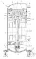
Translated fromKorean도 1은 본 발명에 따른 스크롤 압축기의 진동방지장치가 적용된 스크롤 압축기의 종단면도.1 is a longitudinal sectional view of a scroll compressor to which a vibration suppressing device of a scroll compressor according to the present invention is applied;
도 2는 본 발명에 따른 스크롤 압축기의 진동 방지장치가 적용된 고정 스크롤과 선회 스크롤의 압축수행과정을 나타낸 평면도.Figure 2 is a plan view showing a compression process of the fixed scroll and the swing scroll to which the anti-vibration device of the scroll compressor according to the present invention.
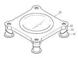
도 3은 본 발명에 따른 스크롤 압축기의 진동방지장치가 적용된 지지부를 나타낸 사시도.Figure 3 is a perspective view showing a support portion to which the anti-vibration device of the scroll compressor according to the present invention.
도 4는 본 발명에 따른 스크롤 압축기의 진동방지장치를 나타낸 분해 사시도.Figure 4 is an exploded perspective view showing a vibration preventing device of the scroll compressor according to the present invention.
도 5는 본 발명에 따른 지지부에 스크롤 압축기로부터 전달되는 힘의 작용상태를 보여주는 스크롤 압축기의 지지부를 나타낸 사시도.Figure 5 is a perspective view showing the support of the scroll compressor showing the action of the force transmitted from the scroll compressor to the support according to the present invention.
도 6은 본 발명에 다른 분산편에 전달되는 힘의 분산 상태를 나타낸 분산편을 나타낸 사시도.Figure 6 is a perspective view showing a dispersion piece showing a dispersion state of the force transmitted to another dispersion piece in the present invention.
< 도면의 주요부분에 대한 부호의 설명> <Description of reference numerals for main parts of the drawings>
41: 상부 그로밋 덮개 42: 상부 그로밋41: upper grommet cover 42: upper grommet
45: 분산편 47: 하부 그로밋45: dispersion piece 47: lower grommets
본 발명은 압축기에 관한 것으로, 더욱 상세하게, 스크롤 압축기의 운전시 스크롤 압축기로부터 스크롤 압축기를 지지하는 그로밋에 전달되는 전달력을 분산하는 스크롤 압축기의 진동방지장치에 관한 것이다.The present invention relates to a compressor, and more particularly, to an anti-vibration device of a scroll compressor for distributing the transmission force transmitted from the scroll compressor to the grommet supporting the scroll compressor during operation of the scroll compressor.
일반적으로 압축기는 기체를 압축시켜 그 압력을 높이는 기계적 장치로서, 크게 디스플레이트먼트형 압축기와, 다이내믹형의 압축기와 스크롤 압축기로 구분된다. 디스플레이스먼트형 압축기는 대표적인 피스톤식 압축기이며, 공장용 압축공기의 공급에 많이 사용된다. 용량은 가정용 냉장고의 압축기처럼 소형도 있으나 보통 시간당 50~25,000 m3 이며, 압력은 최고 3,500기압까지 올릴 수 있다. 이 압축기는 실린더 내의 피스톤의 왕복 운동과 밸브의 개폐(開閉)에 따라 공기를 흡입하여 압축 후 배출하는 사이클로 이루어져 있다. 이 형태는 일반적으로 유량(流量)보다는 높은 압력이 필요할 때 많이 사용된다.그리고 다이내믹형의 압축기는 회전차(回轉差)를 아주 빠른 속도로 회전시켜, 이때 얻어지는 큰 유동속도(流動速度)로 인한 운동량으로 기체의 압력을 상승시키는 장치인데, 큰 유량이 필요할 때 많이 사용된다. 보통 공업용 다이내믹형 압축기는 최대 유량으로 시간당 300,000 m3의 대 형까지 존재하며, 압력은 최대 350기압까지 상승시킬 수 있다.In general, a compressor is a mechanical device that compresses gas to increase pressure, and is classified into a displacement compressor, a dynamic compressor, and a scroll compressor. Displacement type compressors are typical piston compressors and are widely used for supplying compressed air for factories. The capacity is as small as a compressor in a domestic refrigerator, but is usually 50 to 25,000 m3 per hour, and the pressure can be up to 3,500 atm. This compressor consists of a cycle which inhales, compresses, and discharges air according to the reciprocating motion of the piston in the cylinder and the opening and closing of the valve. This type is commonly used when high pressures are required rather than flow rates, and dynamic compressors rotate the rotor at very high speeds, due to the large flow rates obtained. It is a device that raises the pressure of gas by momentum. It is often used when a large flow rate is required. Typically, industrial dynamic compressors can be up to 300,000 m3 per hour at maximum flow rates, and the pressure can be increased up to 350 atm.
특히, 두 개의 나선형(螺旋形) 홈 사이의 기체를 회전에 의해 압축시키는 스크롤 압축기는 공조기 및 냉동기의 압축기로 많이 사용된다. 이러한 스크롤식 압축기는 그 케이싱의 내부에 흡입가스가 충진되는지, 아니면 토출가스가 충진되는지에 다라 저압식 스크롤 압축기 도는 고압식 스크롤 압축기로 나뉘어지게 된다.In particular, scroll compressors that compress the gas between two spiral grooves by rotation are widely used as compressors for air conditioners and refrigerators. Such a scroll compressor is divided into a low pressure scroll compressor or a high pressure scroll compressor depending on whether suction gas is filled or discharge gas is filled in the casing.
상세히, 종래의 저압식 스크롤 압축기는 회전자와 고정자로 이루어지는 구동모터, 상기 구동모터가 회전함에 따라 함께 회전하고, 도한 상부에 편심부가 형성되는 구동축이 포함되는 구동부와, 상기 구동축의 상측에 끼워지는 상부 프레임과, 외부로부터 유체가 유입되도록 하기 위한 흡입관이 포함된다.In detail, a conventional low pressure scroll compressor includes a drive motor including a rotor and a stator, a drive unit including a drive shaft which rotates together as the drive motor rotates, and an eccentric portion is formed at an upper portion thereof, and which is fitted above the drive shaft. An upper frame and a suction pipe for introducing a fluid from the outside are included.
또한, 상기 상부 프레임의 상측에 위치되고, 상기 흡입관을 통해 흡입된 기체를 선회 운동에 의하여 압축하는 선회 스크롤, 상기 선회 스크롤과 맞물려 상기 상부 프레임의 상측에 고정되는 고정 스크롤, 상기 선회 스크롤이 상기 고정 스크롤 내에서 선회될 수 있도록 하는 올담 링이 포함되는 스크롤 압축부와, 상기 고정 스크롤에서 압축된 기체가 외부로 토출되는 토출관이 포함된다.In addition, a swinging scroll positioned above the upper frame and compressing the gas sucked through the suction pipe by turning movement, a fixed scroll engaged with the turning scroll and fixed to the upper side of the upper frame, and the turning scroll is fixed. A scroll compression unit including an Oldham ring to be able to pivot in the scroll, and a discharge pipe through which the gas compressed in the fixed scroll is discharged to the outside.
또한, 상기 스크롤 압축기의 하부에는 소정의 위치에 다수개의 고정볼트가 형성된 베이스 플레이트와, 상기 베이스 플레이트의 고정볼트에 끼워지는 고무 부재 그로밋과, 상기 그로밋에 안착되는 지지브래킷과, 상기 지지브래킷에 끼워진 고정볼트에 차례로 체결되어 스크롤 압축기를 베이스 플레이트에 고정시키는 와셔와 너트가 구비된 진동방지장치가 포함된다.In addition, the lower portion of the scroll compressor is a base plate having a plurality of fixing bolts in a predetermined position, a rubber member grommet fitted to the fixing bolt of the base plate, a support bracket seated on the grommet, and the support bracket It includes a vibration damper having a washer and a nut which are fastened to the fixing bolt in order to fix the scroll compressor to the base plate.
상기되는 구성에 의한 스크롤 압축기의 압축작용을 간단히 설명하도록 한다.The compression operation of the scroll compressor by the above-described configuration will be briefly described.
먼저, 저압상태의 기체가 흡입관을 통하여 유입되고, 이렇게 유입된 기체는 스크롤 압축부로 이동되게 된다. 이와 동시에 상기 회전자와 고정자로 구성된 구동모터가 구동됨에 따라 상기 회전자에 축 결합된 구동축이 회전하게 된다. 그리고 상기 구동축이 회전됨에 따라 상기 구동축의 편심부와 결합되는 상기 선회 스크롤이 선회운동을 하게 되어 상기 기체는 고압의 기체가 된다. 마지막으로 이러한 고압의 기체는 상기 토출관을 통하여 외부로 배출되게 된다.First, the gas in a low pressure state is introduced through the suction pipe, and the introduced gas is moved to the scroll compression unit. At the same time, as the drive motor composed of the rotor and the stator is driven, the drive shaft coupled to the rotor rotates. As the drive shaft rotates, the swing scroll coupled with the eccentric portion of the drive shaft rotates, and the gas becomes a high pressure gas. Finally, the high pressure gas is discharged to the outside through the discharge pipe.
한편, 상기와 같은 압축과정이 수행되는 동안 상기 회전자는 고속으로 회전되게 된다. 이러한 고속회전의 회전자에 의하여 가진원이 발생한다. 그리고 상기 압축부의 압축과정에서도 스크롤 압축기의 작용상의 특성으로 가진원이 발생하게 된다. 이렇게 발생된 가진원은 상기 스크롤 압축기의 케이스로 통하여 상기 베이스 플레이트로 전달되고, 베이스 플레이트로 전달된 가진원은 다시 상기 그로밋에 의하여 감쇄되어 약화 된다.On the other hand, the rotor is rotated at a high speed during the compression process as described above. The excitation circle is generated by the rotor of the high speed rotation. In the compression process of the compression unit, an excitation circle is generated as a characteristic of the scroll compressor. The generated excitation circle is transferred to the base plate through the case of the scroll compressor, and the excitation circle delivered to the base plate is attenuated and weakened by the grommet again.
그러나, 종래의 고무재질의 그로밋이 포함되는 진동방지장치는, 상기 스크롤 압축기의 기동 시 상기 그로밋이 순시 토크에 의하여 과도한 충격을 흡수하지 못하는 단점이 있다.However, the anti-vibration device including the conventional rubber grommet has a disadvantage in that the grommet does not absorb excessive shock due to instantaneous torque when the scroll compressor is started.
또한, 상기 스크롤 압축기가 정상으로 운전되는 경우 피로파괴되는 단점이 있다.In addition, there is a disadvantage that fatigue is broken when the scroll compressor is operated normally.
본 발명은 상기와 같은 문제점을 해결하기 위하여 제안된 것으로서, 상기 스 크롤 압축기의 기동 시 상기 그로밋이 기동 토크에 의하여 과도한 충격을 흡수 가능하게 하며, 상기 스크롤 압축기가 정상으로 운전되는 경우 피로파괴되는 것을 방지하는 스크롤 압축기의 진동방지장치를 제공함을 그 목적으로 한다.The present invention has been proposed to solve the above problems, the grommet to absorb the excessive shock by the starting torque when the scroll compressor is started, it is to be fatigued when the scroll compressor is operating normally It is an object of the present invention to provide an anti-vibration device for a scroll compressor.
상기된 바와 같은 목적을 달성하기 위한 본 발 명에 따른 스크롤 압축기의 진동방지장치는 베이스 플레이트; 상기 베이스 플레이트를 지지하는 상부 그로밋과, 상기 상부 그로밋을 지지하는 하부 그로밋; 상기 상부 그로밋과 상기 하부 그로밋 사이에 경사지게 개재되어 상기 베이스 플레이트로부터 전달되는 전달력이 분산되도록 하는 분산편이 포함된다.Vibration preventing device of the scroll compressor according to the present invention for achieving the object as described above is a base plate; An upper grommet supporting the base plate and a lower grommet supporting the upper grommet; Dispersion pieces are interposed obliquely between the upper grommets and the lower grommets to distribute the transmission force transmitted from the base plate.
본 발명에 따른 스크롤 압축기의 진동방지장치에 의하여, 상기 스크롤 압축기의 기동 시 상기 그로밋이 기동 토크에 의하여 과도한 충격을 흡수 가능하게 하며, 상기 스크롤 압축기가 정상으로 운전되는 경우, 피로파괴되는 것이 방지되는 효과가 있다.By the anti-vibration device of the scroll compressor according to the present invention, when the scroll compressor is started, the grommet can absorb the excessive shock by the starting torque, and when the scroll compressor is operated normally, fatigue is prevented from being destroyed. It works.
이하에서는 본 발명의 구체적인 실시예를 도면과 함께 상세히 설명하도록 한다. 그러나, 본 발명의 사상이 제시되는 실시예에 제한된다고 할 수 없으며, 또다른 구성요소의 추가, 변경, 삭제등에 의해서, 퇴보적인 다른 발명이나 본 발명 사상의 범위 내에 포함되는 다른 실시예를 용이하게 제안할 수 있다.Hereinafter, specific embodiments of the present invention will be described in detail with reference to the accompanying drawings. However, the spirit of the present invention is not limited to the embodiments presented, and other embodiments included within the scope of other inventive inventions or the scope of the present invention can be easily made by adding, changing, or deleting other elements. I can suggest.
도 1은 본 발명에 따른 스크롤 압축기의 진동방지장치가 적용된 스크롤 압축기의 종단면도이다.1 is a longitudinal sectional view of a scroll compressor to which a vibration suppressing device of a scroll compressor according to the present invention is applied.
도 1을 참조하면, 본 발명에 따른 스크롤 압축기의 진동방지장치가 적용된 스크롤 압축기(1)는 케이싱(10)과, 외부에서 유체가 흡입되는 흡입부와, 상기 흡입부로부터 흡입된 유체가 압축되는 스크롤 압축부와, 상기 스크롤 압축부에 의해 압축된 고압의 유체가 토출되는 토출부와, 상기 케이싱(10) 하부에 형성된 오일 저유부(12)와, 상기 오일 저유부(12)에 저장된 오일을 펌핑하는 오일펌프(50)와, 고정자(62)와 회전자(61)의 자기적 상호작용에 의해 회전력이 발생되는 구동모터(60)로 구성되는 구동부와, 상기 회전자(61)에 압입되어 상기 스크롤 압축부와 상기 오일펌프(50)로 회전력을 전달하는 구동축(54)과, 상기 스크롤 압축기를 지지하는 지지부와, 상기 스크롤 압축기에서 발생 되는 진동을 감쇄시키는 진동방지장치(40);가 포함된다.Referring to FIG. 1, the
상세히, 상기 흡입부는 상기 케이싱(10)의 외주면 일측에 형성된 흡입관(95)과, 상기 흡입관(95)과 연통되며 유입된 냉매가 축적되는 흡입실(96)이 포함된다. 한편, 상기 유입된 냉매의 일부는 후술하는 스크롤 압축부로 유입되어 압축된다.In detail, the suction part includes a
또한, 상기 토출부는 상기 고정 스크롤(90)의 중앙부에 형성되어 압축된 냉매를 내보내는 토출 포트(92)와, 상기 토출 포트(92)와 연통되고, 상기 케이싱(10)의 최상측에 형성되는 토출실(93)과, 상기 토출실(93)의 일측면에 형성되는 토출관(94)이 포함된다.In addition, the discharge portion is formed in the center portion of the
또한, 상기 구동부는 고정자(62)과 회전자(61)로 구성된 구동 모터(60)로써 형성된다. 그리고 상기 회전자(21)는 상기 고정자(22)와 자기적 작용에 의하여 회전력을 발생시킨다. 이러한 회전력은 상기 구동축(54)을 통하여 상기 오일펌프(50) 와 상기 스크롤 압축부로 전달된다. 그리고 상기 회전력에 의해 발생 되는 토션은 후술하는 지지부를 통하여 흡수 감쇄된다.In addition, the drive unit is formed as a
또한, 상기 오일 펌프(50)는 인너 기어(51)와 아우터 기어(52)로 내접 기어 펌프로 구성된다. 이러한 상기 오일 펌프(50)은 상기 하부 프레임(64)에 형성된 삽입홀에 삽입된 상태에서 상기 오일펌프(50)의 하측 커버 역할을 하는 펌프커버(65)가 상기 하부 프레임(64)에 체결됨에 따라 상기 삽입홀에 실장된다. 상세히, 상기 오일펌프(50)는 상기 인어 기어(51)와 아우터 기어(52) 사이에 형성되는 챔버로 오일이 흡입된 상태에서, 상기 구동축(54)이 회전되면, 인너 기어(51)의 회전과 함께 아우터 기어(52)가 회전된다. 그리고, 상기 인너 기어(51)와 아우터 기어(52)가 회전됨에 따라 상기 챔버 내의 오일은 상기 오일 공급통로(53)를 따라 상승하게 된다. 이러한 오일은 상기 선회 스크롤 스러스트 베어링면(82)과 상기 상부 프레임 스러스트 베어링 면(66)에 스며들어 윤활 작용을 한다.In addition, the oil pump 50 is composed of an internal gear pump with an inner gear 51 and an
또한, 상기 스크롤 압축부는 상기 구동축(54)의 상부에 끼워져서 상기 구동축(54)을 지지하는 상부 프레임(63)과, 상기 흡입관(95)을 통하여 흡입된 냉매를 압축할 수 있도록 상기 상부 프레임(63) 상측에 의하여 지지 되는 선회 스크롤(80)과, 상기 선회 스크롤(80)과 맞물려 상기 상부 프레임(63)의 상측에 체결수단에 의하여 고정되는 고정 스크롤(90)과, 상기 고정 스크롤(90)의 하측에 스파이럴 형상으로 형성되어 있는 고정 스크롤 랩(91)과, 상기 선회 스크롤(80)의 상측에 스파이럴 형상으로 형성되고, 상기 고정 스크롤 랩(91)에 대하여 180도 엇갈려 삽입되는 선회 스크롤 랩(81)과, 상기 고정 스크롤 랩(91)의 내측 중심부에 형성되는 토출 포트(92)가 포함된다.In addition, the scroll compression unit is inserted into the upper portion of the
도 2는 본 발명에 따른 스크롤 압축기의 진동 방지장치가 적용된 고정 스크롤과 선회 스크롤의 압축수행과정을 나타낸 평면도이다.2 is a plan view illustrating a compression process of the fixed scroll and the swing scroll to which the vibration preventing device of the scroll compressor according to the present invention is applied.
상기와 같은 구성을 가지는 스크롤 압축부에서 냉매가 압축되는 과정을 설명하면, 먼저, 상기 선회 스크롤(80)이 상기 구동축(54)을 중심으로 편심되어 선회(공전)하게 된다. 그리고 상기 선회 스크롤(80)이 상기 고정 스크롤(90)에 대하여 상기 구동축(54)의 회전에 의하여 선회운동 되어, 각각의 스크롤 랩(81)(91)들이 면접촉을 일으켜 냉매를 압축하는 포켓(83)이 형성된다. 이러한 포켓(83)은 상기 스크롤 랩(81)(91)의 중심부로 회전하면서 들어가 그 체적이 작아진다. 이렇게 체적이 작아진 포켓 내부에는 고압상태가 된다. 따라서, 포켓 내부에 존재하는 냉매는 고압의 냉매가 되어 상기 토출 포트(92)를 통하여 토출실(93)로 토출 된다.Referring to the process of compressing the refrigerant in the scroll compression unit having the configuration described above, first, the
또한, 상기 케이싱 바닥 플레이트(11)는 상기 스크롤 압축기(1)의 바닥면을 형성하며, 상면에 상기 저유부(12)가 마련되도록 한다. 그리고 상기 케이싱 바닥 플레이트(11)의 외곽 4곳에 후술하는 진동방지장치(40)가 고정되도록 하는 체결홀이 형성된다.In addition, the
도 3은 본 발명에 따른 스크롤 압축기의 진동방지장치가 적용된 지지부를 나타낸 사시도이다.3 is a perspective view showing a support portion to which the anti-vibration device of the scroll compressor according to the present invention is applied.
도 3을 참조하면, 본 발명에 따른 지지부는 상기 케이싱 바닥 플레이트(11)의 하면에 결합되는 베이스 플레이트(20)와, 상기 베이스 플레이트(20)의 하면에 체결부재(30) 의하여 결합되는 진동방지장치(40)가 포함된다.Referring to FIG. 3, the support part according to the present invention is a
상세히,상기 베이스 플레이트(20)는 상기 케이싱 바닥 플레이트(20)에 밀착되어 상기 스크롤 압축기(1)를 지지한다. 그리고 상기 베이스 플레이트(20)의 외곽 4곳에 후술하는 진동방지장치(40)가 고정되도록 하는 체결홀이 형성된다.In detail, the
도 4는 본 발명에 따른 스크롤 압축기의 진동방지장치를 나타낸 분해 사시도이다.Figure 4 is an exploded perspective view showing a vibration preventing device of the scroll compressor according to the present invention.
도 4를 참조하면, 본 발명에 따른 스크롤 압축기의 진동방지장치(40)는 상기 스크롤 압축기(1)에서 발생 되는 진동을 일차적으로 흡수하는 상부 그로밋(43)과, 상기 상부 그로밋(43)과 상기 베이스 플레이트(20) 사이에 개재되어 상기 상부 그로밋(43)의 진동 파괴를 방지하는 상부 그로밋 덮개(41)와, 상기 상부 그로밋(43)의 하부 절개면(44)에 밀착되어 진동력을 분산하는 분산편(45)과, 상기 분산편(45)을 통하여 분산된 진동을 이차적으로 흡수하는 하부 그로밋(47)이 포함된다.Referring to FIG. 4, the
상세히, 상기 상부 그로밋 덮개(41)는 상기 방진 장치(40)가 상기 베이스 플레이트(20)에 결합 될 시 상기 상부 그로밋(43)와 상기 베이스 플레이트(20)사이에 개재되게 된다. 그리고 상부 그로밋 덮개(41)의 재질은 상기 스크롤 압축기(1)의 구동시 전달되는 진동과 하중을 충분치 견딜 수 있는 소재로 제작되며, 바람직하게는 소정의 강성을 가지는 금속 소재가 사용될 수 있다. 이러한 상기 상부 그로밋 덮개(41)는 상기 상부 그로밋(43)과 상기 베이스 플레이트(20)과의 접촉 특성을 향상시킨다. 그리고 상기 상부 그로밋 덮개(41)는 상기 상부 그로밋(43)과 상기 베이스 플레이트(20)과의 상호 작용을 안정화한다. 다시 말하면, 상기 스크롤 압축기(1)의 하중이 일측에 모아 지게 되면, 상기 일측에 힘이 모아진 부분에 설치된 방 진 장치(40)의 상기 상부 그로밋(43)을 가압하게 된다. 그런데, 상기 상부 그로밋(43)은 진동을 효과적으로 흡수하기 위하여, 그 재질이 고무 부재 등으로 형성된다. 따라서, 상기 베이스 플레이트(20)와의 접촉에 의하여, 상부 그로밋(43)의 상부면이 파손되는 현상이 발생한다. 이러한 상부 그로밋(43)의 파손현상을 상기 상부 그로밋 덮개(43)에 의하여 방지될 수 있다. 이렇게 함으로써, 상기 상부 그로밋 덮개(41)는 상기 상부 그로밋(41)과 상기 베이스 플레이트(20)의 상호 작용을 안정화한다.In detail, the
또한, 상기 상부 그로밋(41)은 대략 원기둥 모양으로 외주면의 소정위치로부터 상부면(42)으로 소정의 각도를 가지고 좁아지는 모양을 갖는다. 그리고 상기 상부 그로밋(41)의 내부에는 후술하는 체결 부재(30)가 관통될 수 있도록 하는 관통홀이 형성된다. 그리고 상기 상부면(42)에 상기 상부 그로밋 덮개(41)가 안착 된다. 그리고 상기 상부 그로밋(41) 하측 외주면의 소정위치로부터 하방으로 소정의 각도를 가지며 절개된 하부 절개면(44)이 형성된다. 이러한 하부 절개면(44)과 하부 그로밋(47)의 상부 절개면(46) 사이에 분산편(45)가 개재된다.In addition, the
또한, 상기 하부 그로밋(47)은 대략 원기둥 모양으로 외주면의 소정위치로부터 상방으로 경사지게 절개되는 상부 절개면(46)이 형성된다. 그리고 상기 하부 그로밋(47)의 내부에는 상기 체결 부재(30)가 관통되는 관통홀이 형성된다. 여기서, 상기 하부 그로밋(47)의 재질은 바람직하게는 고무 부재가 사용됨을 밝혀둔다.In addition, the
한편, 상기 상부 그로밋(43)과 상기 하부 그로밋(47)은 소정의 탄성력을 가지며 진동을 흡수하는 성질을 가지는 고무 부재가 바람직함을 밝혀둔다. 그리고, 상기 하부 절개면(44)과 상기 상부 절개면(46)은 상기 스크롤 압축기(1)의 진동을 효과적으로 흡수함과 아울러 상기 진동이 바람직하게 분산될 수 있도록 하기 위하여, 수평면에 대하여 소정의 각을 가지며 형성됨을 밝혀둔다.On the other hand, the
또한, 상기 분산편(45)은 중앙에 후술하는 체결 부재(30)가 관통될 수 있도록하는 관통홀이 형성된 타원 원반 형상의 모양을 가진다. 그리고, 상기 분산편(45)은 소정의 강성을 가지는 금속 부재가 바람직하다. 이러한 상기 분산편(45)은 상기 스크롤 압축기(1)에서 발생 되어 상기 상부 그로밋(43)을 통하여 전달되는 진동 전달력이 수평 방향과 수직 방향으로 분산되게 한다. 이렇게, 상기 진동력이 분산되어 상기 스크롤 압축기(1)의 진동이 감쇄된다.In addition, the
한편, 상기와 같은 진동방지장치(40)는 상기 체결 부재(30)가 상기의 관통홀을 관통하여 상기 케이싱 바닥 플레이트(11)에 체결된다. 이러한 체결 부재(30)는 바람직하게 볼트(32)와 너트(31)로 구성된다.On the other hand, the
이하, 상기와 같은 구성에 의한 스크롤 압축기의 작용에 대하여 도면과 함께설명하도록 한다.Hereinafter, the operation of the scroll compressor by the above configuration will be described with reference to the drawings.
도 5는 본 발명에 따른 지지부에 스크롤 압축기로부터 전달되는 힘의 작용상태를 보여주는 스크롤 압축기의 지지부를 나타낸 사시도이고, 도 6은 본 발명에 다른 분산편에 전달되는 힘의 분산 상태를 나타낸 분산편을 나타낸 사시도이다.Figure 5 is a perspective view showing the support of the scroll compressor showing a state of action of the force transmitted from the scroll compressor to the support according to the invention, Figure 6 is a dispersion piece showing a dispersion state of the force transmitted to another dispersion piece in the present invention It is a perspective view shown.
상기 스크롤 압축기의 작동은 먼저, 전원이 인가되어 구동부가 작동함에 다라 구동부의 회전자(61)가 회전하게 되어 회전력이 발생된다. 이러한 회전력은 상기 회전자(61)에 압입된 구동축(54)을 통하여 상기 선회 스크롤(80)으로 전달된다. 이렇게 회전력을 전달받은 선회 스크롤(80)은 올담 링에 의해 자전이 방지되면서 상기 선회 스크롤 랩(52)이 상기 고정 스크롤 랩(72)과 맞물려 선회 운동을 하게 된다. 그리고 상기 선회 스크롤(80)의 선회 운동에 의해 흡입관(95)을 통해 흡입된 유체가 상기 고정 스크롤(90)의 일측에 형성된 흡입구(도면에 도시되디 않음)를 통해 상기 고정 스크롤 랩(91)과 상기 선회 스크롤 랩(81) 사이로 흡입되어 가운데 부분으로 이동됨과 동시에 압축되면서 상기 고정 스크롤(90)에 형성된 토출 포트(92)를 통해 토출 되는 고온고압 상태의 유체 상태가 되어 상기 토출관(94)을 통해 토출된다.In operation of the scroll compressor, first, power is applied to the driving unit, and the
한편, 도 5를 참조하면, 상기 스크롤 압축기(1)의 회전자(61)로부터 발생되는 진동력은 회전토션(A)과 수직 하강/상승의 진동(B,C)이 발생 된다. 상기 수직 상승/하강의 진동(B,C)은 상기 상부 그로밋(43)에 작용하여 상기 상부 그로밋(43)을 피로 파괴하게 되는데 이러한 피로 파괴현상은 상기 상부 그로밋 덮개(41)에 의하여 보호된다. 그리고 상기 회전토션과 상기 수직 하강/상승의 진동의 합력(D)은 도 6과 같이 상기 분산편(45)에 의하여, 분산력(d1, d2)으로 분산되어 감쇄된다. 이러한 힘의 분산은 상기 스크롤 압축기(1)에서 발생되는 진동을 현저히 감소시킨다.Meanwhile, referring to FIG. 5, the vibration force generated from the
본 발명에 따른 스크롤 압축기의 진동방지장치에 의하여, 상기 스크롤 압축기의 기동 시 상기 그로밋이 기동 토크에 의하여 과도한 충격을 흡수 가능하게 하 며, 상기 스크롤 압축기가 정상으로 운전되는 경우, 피로파괴되는 것이 방지되는 효과가 있다.By the anti-vibration device of the scroll compressor according to the present invention, when the scroll compressor is started, the grommet can absorb the excessive shock by the starting torque, and when the scroll compressor is operated normally, it is prevented from fatigue destruction It is effective.
더 나아가서, 효과적으로 진동이 방지되어, 스크롤 압축기에서 발생 되는 충격소음이 감소 되는 부수적인 효과도 있다.Furthermore, there is a side effect that the vibration is effectively prevented, so that the impact noise generated in the scroll compressor is reduced.
Claims (5)
Translated fromKoreanPriority Applications (3)
| Application Number | Priority Date | Filing Date | Title |
|---|---|---|---|
| KR1020050133379AKR100738708B1 (en) | 2005-12-29 | 2005-12-29 | Anti-vibration device of scroll compressor |
| US11/647,557US8033798B2 (en) | 2005-12-29 | 2006-12-29 | Compressor vibration damper |
| CN2006101720819ACN1991176B (en) | 2005-12-29 | 2006-12-29 | Compressor vibration damper |
Applications Claiming Priority (1)
| Application Number | Priority Date | Filing Date | Title |
|---|---|---|---|
| KR1020050133379AKR100738708B1 (en) | 2005-12-29 | 2005-12-29 | Anti-vibration device of scroll compressor |
Publications (2)
| Publication Number | Publication Date |
|---|---|
| KR20070070627A KR20070070627A (en) | 2007-07-04 |
| KR100738708B1true KR100738708B1 (en) | 2007-07-12 |
Family
ID=38213631
Family Applications (1)
| Application Number | Title | Priority Date | Filing Date |
|---|---|---|---|
| KR1020050133379AExpired - Fee RelatedKR100738708B1 (en) | 2005-12-29 | 2005-12-29 | Anti-vibration device of scroll compressor |
Country Status (3)
| Country | Link |
|---|---|
| US (1) | US8033798B2 (en) |
| KR (1) | KR100738708B1 (en) |
| CN (1) | CN1991176B (en) |
Families Citing this family (18)
| Publication number | Priority date | Publication date | Assignee | Title |
|---|---|---|---|---|
| US8002528B2 (en)* | 2006-09-18 | 2011-08-23 | Emerson Climate Technologies, Inc. | Compressor assembly having vibration attenuating structure |
| US20100132023A1 (en)* | 2008-11-21 | 2010-05-27 | Randall Reese | Machine, Program Product, And Computer-Implemented Method For File Management, Storage, And Display In Albums Utilizing A Questionnaire |
| BR112014000964B1 (en)* | 2011-07-19 | 2021-01-05 | Koninklijke Philips N.V. | household appliance |
| CN108278452B (en)* | 2017-01-06 | 2020-12-22 | 青岛海尔洗衣机有限公司 | Foot for household appliance and household appliance |
| CN107044421B (en) | 2017-06-06 | 2019-07-26 | 珠海格力电器股份有限公司 | air conditioning unit, compressor and shell structure thereof |
| CN107420302A (en)* | 2017-08-22 | 2017-12-01 | 东莞市容邦尚电子科技有限公司 | A vertical anti-vibration vehicle-mounted oil-free scroll air compressor |
| JP6686994B2 (en)* | 2017-09-20 | 2020-04-22 | ダイキン工業株式会社 | Scroll compressor |
| USD912762S1 (en) | 2017-11-29 | 2021-03-09 | Megadyne Medical Products, Inc. | Fluid trap |
| US10758293B2 (en) | 2017-11-29 | 2020-09-01 | Megadyne Medical Products, Inc. | Smoke evacuation device inlet and outlet manifolds |
| US10758856B2 (en) | 2017-11-29 | 2020-09-01 | Megadyne Medical Products, Inc. | Filter medium compression system for smoke evacuation |
| USD868236S1 (en) | 2017-11-29 | 2019-11-26 | Megadyne Medical Products, Inc. | Smoke evacuation device control panel |
| US11725664B2 (en) | 2017-11-29 | 2023-08-15 | Megadyne Medical Products, Inc. | Noise and vibration management for smoke evacuation system |
| USD868287S1 (en) | 2017-11-29 | 2019-11-26 | Megadyne Medical Products, Inc. | Remote activation clip |
| US11389225B2 (en) | 2017-11-29 | 2022-07-19 | Megadyne Medical Products, Inc. | Smoke evacuation device remote activation system |
| US11234754B2 (en) | 2017-11-29 | 2022-02-01 | Megadyne Medical Products, Inc. | Smoke evacuation device |
| US10631916B2 (en) | 2017-11-29 | 2020-04-28 | Megadyne Medical Products, Inc. | Filter connection for a smoke evacuation device |
| US10758855B2 (en) | 2017-11-29 | 2020-09-01 | Megadyne Medical Products, Inc. | Smoke evacuation system fluid trap |
| USD886976S1 (en) | 2017-11-29 | 2020-06-09 | Megadyne Medical Products, Inc. | Filter cartridge |
Citations (7)
| Publication number | Priority date | Publication date | Assignee | Title |
|---|---|---|---|---|
| JPH0510263A (en)* | 1991-07-03 | 1993-01-19 | Matsushita Refrig Co Ltd | Vibration isolation device for vibration generating device |
| JPH06147127A (en)* | 1992-11-13 | 1994-05-27 | Copeland Corp | Tandem type sealed type compressor |
| KR200165729Y1 (en)* | 1997-10-14 | 2000-01-15 | 배길성 | Vibration isolation device of a hermetic compressor |
| KR20000001863U (en)* | 1998-06-30 | 2000-01-25 | 전주범 | Fixing bolt of air conditioner compressor |
| JP2002235665A (en)* | 2001-02-06 | 2002-08-23 | Fujitsu General Ltd | Support apparatus of the compressor |
| JP2005036762A (en)* | 2003-07-18 | 2005-02-10 | Aisan Ind Co Ltd | Mounting member and mounting structure for pump |
| US6960070B2 (en)* | 2002-10-15 | 2005-11-01 | Bitzer Kuehlmaschinenbau Gmbh | Compressor |
Family Cites Families (32)
| Publication number | Priority date | Publication date | Assignee | Title |
|---|---|---|---|---|
| US2262442A (en)* | 1940-06-29 | 1941-11-11 | Mathews Conveyer Co | Roller conveyer |
| US4161812A (en)* | 1975-12-01 | 1979-07-24 | General Electric Company | Methods of securing torsionally flexible motor mounting arrangements to supports therefor |
| US5221192A (en)* | 1992-07-16 | 1993-06-22 | Carrier Corporation | Elastomeric compressor stud mount |
| US5788207A (en)* | 1994-10-11 | 1998-08-04 | Bunker; Donald D. | Automotive transmission mount |
| JP3081955B2 (en)* | 1995-08-23 | 2000-08-28 | 三洋電機株式会社 | Air conditioner |
| WO1997010477A1 (en)* | 1995-09-14 | 1997-03-20 | Daikin Industries, Ltd. | Compact outdoor unit of high heat exchange capacity for air conditioners |
| JPH1193835A (en) | 1997-09-19 | 1999-04-06 | Fujitsu General Ltd | Compressor support device |
| US6301776B1 (en)* | 1998-05-15 | 2001-10-16 | Samsung Electronics Co., Ltd. | System and method for assembling an outdoor unit of a dual-unit type air conditioner |
| US6182460B1 (en)* | 1998-08-26 | 2001-02-06 | Carrier Corporation | Window room air conditioner |
| US6354558B1 (en)* | 1998-11-20 | 2002-03-12 | Carrier Corporation | Compressor mounting |
| KR100315791B1 (en)* | 1999-01-19 | 2001-12-12 | 구자홍 | Scroll Compressor |
| DE19930635A1 (en) | 1999-07-02 | 2001-01-04 | Mannesmann Rexroth Ag | Energy converter for converting electricity to hydraulic power, with electric motor and hydraulic pump independently attached to base frame |
| US6557816B2 (en)* | 2000-02-07 | 2003-05-06 | Fuji Photo Film Co., Ltd. | Motor mounting structure and drive shaft mounting structure |
| US6412298B2 (en)* | 2000-04-29 | 2002-07-02 | Lg Electronics Inc. | Window type air conditioner |
| US6505806B1 (en)* | 2000-05-09 | 2003-01-14 | Husky Injection Molding Systems, Ltd. | Dynamic machine mount |
| KR100390783B1 (en)* | 2001-01-31 | 2003-07-10 | 주식회사 엘지이아이 | Scroll compressor |
| CA2436036C (en)* | 2001-04-07 | 2011-02-22 | Lg Electronics Inc. | Apparatus and method for controlling cold air circulation in refrigerator |
| KR100397561B1 (en)* | 2001-08-20 | 2003-09-13 | 주식회사 엘지이아이 | Apparatus for preventing over-load in scroll compressor |
| KR100441000B1 (en)* | 2001-11-08 | 2004-07-21 | 삼성전자주식회사 | An air conditioning system with fan-casing |
| KR100423970B1 (en)* | 2001-11-24 | 2004-03-22 | 삼성전자주식회사 | Air conditioner and control method thereof |
| KR20030089819A (en)* | 2002-05-20 | 2003-11-28 | 엘지전자 주식회사 | Compressor base cover of refrigerator |
| US6695600B2 (en)* | 2002-05-28 | 2004-02-24 | Lg Electronics Inc. | Scroll compressor |
| US6779988B2 (en)* | 2002-10-07 | 2004-08-24 | Chih-Ming Chen | Structure of a base for a mini air compressor |
| ES2553572T3 (en)* | 2002-11-21 | 2015-12-10 | Lg Electronics Inc. | Air conditioning apparatus |
| US7032404B2 (en)* | 2003-01-24 | 2006-04-25 | Lg Electronics Inc. | Air conditioner |
| KR100512677B1 (en)* | 2003-02-21 | 2005-09-07 | 삼성전자주식회사 | Refrigerator |
| KR20040077234A (en)* | 2003-02-28 | 2004-09-04 | 엘지전자 주식회사 | shockdown rubber for compressor in refrigerator |
| US6772601B1 (en)* | 2003-03-12 | 2004-08-10 | Maytag Corporation | Temperature control system for a refrigerated compartment |
| KR20050019591A (en)* | 2003-08-20 | 2005-03-03 | 삼성전자주식회사 | Integration Type Air Conditioner Having Condenser Casing |
| CN2646188Y (en) | 2003-09-29 | 2004-10-06 | 中国船舶重工集团公司第七一一研究所 | Oblique type light rail vibration damper |
| EP1524484A1 (en)* | 2003-10-16 | 2005-04-20 | Whirlpool Corporation | Refrigerator |
| KR100547334B1 (en) | 2004-02-10 | 2006-01-26 | 엘지전자 주식회사 | Pipe structure of air conditioner |
- 2005
- 2005-12-29KRKR1020050133379Apatent/KR100738708B1/ennot_activeExpired - Fee Related
- 2006
- 2006-12-29USUS11/647,557patent/US8033798B2/ennot_activeExpired - Fee Related
- 2006-12-29CNCN2006101720819Apatent/CN1991176B/ennot_activeExpired - Fee Related
Patent Citations (7)
| Publication number | Priority date | Publication date | Assignee | Title |
|---|---|---|---|---|
| JPH0510263A (en)* | 1991-07-03 | 1993-01-19 | Matsushita Refrig Co Ltd | Vibration isolation device for vibration generating device |
| JPH06147127A (en)* | 1992-11-13 | 1994-05-27 | Copeland Corp | Tandem type sealed type compressor |
| KR200165729Y1 (en)* | 1997-10-14 | 2000-01-15 | 배길성 | Vibration isolation device of a hermetic compressor |
| KR20000001863U (en)* | 1998-06-30 | 2000-01-25 | 전주범 | Fixing bolt of air conditioner compressor |
| JP2002235665A (en)* | 2001-02-06 | 2002-08-23 | Fujitsu General Ltd | Support apparatus of the compressor |
| US6960070B2 (en)* | 2002-10-15 | 2005-11-01 | Bitzer Kuehlmaschinenbau Gmbh | Compressor |
| JP2005036762A (en)* | 2003-07-18 | 2005-02-10 | Aisan Ind Co Ltd | Mounting member and mounting structure for pump |
Also Published As
| Publication number | Publication date |
|---|---|
| US20070177994A1 (en) | 2007-08-02 |
| CN1991176B (en) | 2011-06-01 |
| KR20070070627A (en) | 2007-07-04 |
| US8033798B2 (en) | 2011-10-11 |
| CN1991176A (en) | 2007-07-04 |
Similar Documents
| Publication | Publication Date | Title |
|---|---|---|
| KR100738708B1 (en) | Anti-vibration device of scroll compressor | |
| US11248608B2 (en) | Compressor having centrifugation and differential pressure structure for oil supplying | |
| KR100867623B1 (en) | Compressor Vibration Reduction Device | |
| KR20130055407A (en) | Rotary compressor and manufacturing method thereof | |
| US20070183917A1 (en) | Foam reduction device for a compressor | |
| EP2148988A1 (en) | Compressor and oil supplying structure therefor | |
| CN1135300C (en) | Rotary compressor, refrigerating circulation and ice house using same | |
| CN100501158C (en) | compressor | |
| CN112703317A (en) | Compressor | |
| US10816000B2 (en) | Compressor having centrifugation structure for supplying oil | |
| CN100339597C (en) | Closed compressor | |
| CN101187371A (en) | Compressor vibration damping mat | |
| JP6686994B2 (en) | Scroll compressor | |
| KR101462934B1 (en) | Hermetic compressor | |
| KR20050097341A (en) | Horizontal type enclosed compressor having auxiliary viration reduction device | |
| KR100417590B1 (en) | Apparatus for reducing vibration of compressor | |
| KR102550657B1 (en) | Scroll compressor having vibration reduction structure | |
| CN213899291U (en) | Compression assembly, compressor and heat exchange device | |
| KR950004771Y1 (en) | Overpressure prevention structure of scroll compressor | |
| KR100279606B1 (en) | Bearing supporter of turbo compressor | |
| KR100677271B1 (en) | Swivel scroll support device of scroll compressor | |
| CN100436829C (en) | Rotary compressor | |
| KR100273398B1 (en) | Radial bearing for turbo compressor | |
| KR20040044028A (en) | Vibration reducing structure of compressor | |
| KR20060032487A (en) | Anti-rotation device of scroll compressor |
Legal Events
| Date | Code | Title | Description |
|---|---|---|---|
| A201 | Request for examination | ||
| PA0109 | Patent application | St.27 status event code:A-0-1-A10-A12-nap-PA0109 | |
| PA0201 | Request for examination | St.27 status event code:A-1-2-D10-D11-exm-PA0201 | |
| D13-X000 | Search requested | St.27 status event code:A-1-2-D10-D13-srh-X000 | |
| D14-X000 | Search report completed | St.27 status event code:A-1-2-D10-D14-srh-X000 | |
| E902 | Notification of reason for refusal | ||
| PE0902 | Notice of grounds for rejection | St.27 status event code:A-1-2-D10-D21-exm-PE0902 | |
| E13-X000 | Pre-grant limitation requested | St.27 status event code:A-2-3-E10-E13-lim-X000 | |
| P11-X000 | Amendment of application requested | St.27 status event code:A-2-2-P10-P11-nap-X000 | |
| P13-X000 | Application amended | St.27 status event code:A-2-2-P10-P13-nap-X000 | |
| E701 | Decision to grant or registration of patent right | ||
| PE0701 | Decision of registration | St.27 status event code:A-1-2-D10-D22-exm-PE0701 | |
| PG1501 | Laying open of application | St.27 status event code:A-1-1-Q10-Q12-nap-PG1501 | |
| GRNT | Written decision to grant | ||
| PR0701 | Registration of establishment | St.27 status event code:A-2-4-F10-F11-exm-PR0701 | |
| PR1002 | Payment of registration fee | St.27 status event code:A-2-2-U10-U11-oth-PR1002 Fee payment year number:1 | |
| PG1601 | Publication of registration | St.27 status event code:A-4-4-Q10-Q13-nap-PG1601 | |
| PN2301 | Change of applicant | St.27 status event code:A-5-5-R10-R13-asn-PN2301 St.27 status event code:A-5-5-R10-R11-asn-PN2301 | |
| R18-X000 | Changes to party contact information recorded | St.27 status event code:A-5-5-R10-R18-oth-X000 | |
| R18-X000 | Changes to party contact information recorded | St.27 status event code:A-5-5-R10-R18-oth-X000 | |
| L13-X000 | Limitation or reissue of ip right requested | St.27 status event code:A-2-3-L10-L13-lim-X000 | |
| U15-X000 | Partial renewal or maintenance fee paid modifying the ip right scope | St.27 status event code:A-4-4-U10-U15-oth-X000 | |
| PR1001 | Payment of annual fee | St.27 status event code:A-4-4-U10-U11-oth-PR1001 Fee payment year number:4 | |
| PR1001 | Payment of annual fee | St.27 status event code:A-4-4-U10-U11-oth-PR1001 Fee payment year number:5 | |
| PR1001 | Payment of annual fee | St.27 status event code:A-4-4-U10-U11-oth-PR1001 Fee payment year number:6 | |
| FPAY | Annual fee payment | Payment date:20130624 Year of fee payment:7 | |
| PR1001 | Payment of annual fee | St.27 status event code:A-4-4-U10-U11-oth-PR1001 Fee payment year number:7 | |
| FPAY | Annual fee payment | Payment date:20140624 Year of fee payment:8 | |
| PR1001 | Payment of annual fee | St.27 status event code:A-4-4-U10-U11-oth-PR1001 Fee payment year number:8 | |
| PN2301 | Change of applicant | St.27 status event code:A-5-5-R10-R13-asn-PN2301 St.27 status event code:A-5-5-R10-R11-asn-PN2301 | |
| LAPS | Lapse due to unpaid annual fee | ||
| PC1903 | Unpaid annual fee | St.27 status event code:A-4-4-U10-U13-oth-PC1903 Not in force date:20150706 Payment event data comment text:Termination Category : DEFAULT_OF_REGISTRATION_FEE | |
| PC1903 | Unpaid annual fee | St.27 status event code:N-4-6-H10-H13-oth-PC1903 Ip right cessation event data comment text:Termination Category : DEFAULT_OF_REGISTRATION_FEE Not in force date:20150706 | |
| PN2301 | Change of applicant | St.27 status event code:A-5-5-R10-R13-asn-PN2301 St.27 status event code:A-5-5-R10-R11-asn-PN2301 |