KR100738391B1 - Joint structure of the camera module - Google Patents
Joint structure of the camera moduleDownload PDFInfo
- Publication number
- KR100738391B1 KR100738391B1KR1020050094821AKR20050094821AKR100738391B1KR 100738391 B1KR100738391 B1KR 100738391B1KR 1020050094821 AKR1020050094821 AKR 1020050094821AKR 20050094821 AKR20050094821 AKR 20050094821AKR 100738391 B1KR100738391 B1KR 100738391B1
- Authority
- KR
- South Korea
- Prior art keywords
- barrel
- camera module
- housing
- horizontal contact
- contact surface
- Prior art date
- Legal status (The legal status is an assumption and is not a legal conclusion. Google has not performed a legal analysis and makes no representation as to the accuracy of the status listed.)
- Expired - Fee Related
Links
Images


Classifications
- G—PHYSICS
- G02—OPTICS
- G02B—OPTICAL ELEMENTS, SYSTEMS OR APPARATUS
- G02B5/00—Optical elements other than lenses
- G02B5/20—Filters
- G02B5/208—Filters for use with infrared or ultraviolet radiation, e.g. for separating visible light from infrared and/or ultraviolet radiation
Landscapes
- Physics & Mathematics (AREA)
- Health & Medical Sciences (AREA)
- Toxicology (AREA)
- General Physics & Mathematics (AREA)
- Optics & Photonics (AREA)
- Lens Barrels (AREA)
- Studio Devices (AREA)
Abstract
Translated fromKoreanDescription
Translated fromKorean도 1은 종래 카메라 모듈이 개략적으로 도시된 단면도.1 is a cross-sectional view schematically showing a conventional camera module.
도 2는 종래 카메라 모듈의 분해 사시도.Figure 2 is an exploded perspective view of a conventional camera module.
도 3은 본 발명에 따른 카메라 모듈의 조립 사시도.3 is an assembled perspective view of the camera module according to the present invention.
도 4는 본 발명에 따른 카메라 모듈의 조립 단면도.4 is an assembled cross-sectional view of the camera module according to the present invention.
도 5는 도 4의 'A' 부분의 확대 단면도.5 is an enlarged cross-sectional view of a portion 'A' of FIG. 4.
<도면의 주요 부분에 대한 부호의 설명><Explanation of symbols for the main parts of the drawings>
100. 카메라 모듈 110. 하우징100.
111. 경통 112. 하부 치합면111.Body barrel 112.Lower tooth surface
113, 124. 수평접촉면 120. 배럴113, 124.
122. 원통형 몸체 123. 상부 치합면122.
113a, 113b. 124a, 124b. 경사면113a, 113b. 124a, 124b. incline
본 발명은 카메라 모듈을 구성하는 하우징과 배럴의 결합 구조에 관한 것으로서, 보다 자세하게는 렌즈가 장착된 배럴과 이미지센서 칩이 내장된 하우징의 조립에 의한 포커싱 공정시 각 부재의 외주면에 형성된 계단식 치합면에 의해서 광축에 대하여 수직 결합될 수 있도록 함으로써, 카메라 모듈의 광축이 틀어지는 것을 방지함과 아울러 해상력이 향상될 수 있도록 한 카메라 모듈의 치합 구조에 관한 것이다.The present invention relates to a coupling structure between a housing constituting a camera module and a barrel, and more particularly, a stepped mating surface formed on an outer circumferential surface of each member during a focusing process by assembling a lens-mounted barrel and an image sensor chip-containing housing. By allowing the vertical coupling with respect to the optical axis by the, to prevent the optical axis of the camera module is twisted, and to the resolution structure of the camera module to improve the resolution.
일반적으로, 카메라 모듈(CCM:COMPACT CAMERA MOUDULE)은 소형으로써 카메라폰이나 PDA, 스마트폰을 비롯한 휴대용 이동통신 기기와 토이 카메라(TOY CAMERA) 등의 다양한 IT 기기에 적용되고 있는 바, 최근에 이르러서는 소비자의 다양한 취향에 맞추어 소형의 카메라 모듈이 장착된 기기의 출시가 점차 늘어나고 있는 실정이다.In general, the camera module (CCM: COMPACT CAMERA MOUDULE) is compact and is applied to various IT devices such as a camera phone, a PDA, a smartphone, and a portable mobile communication device such as a toy camera (TOY CAMERA). Increasingly, devices equipped with small camera modules are gradually being released to meet various consumer tastes.
이와 같은 카메라 모듈은, CCD나 CMOS 등의 이미지센서를 주요 부품으로 하여 제작되고 있으며 상기 이미지센서를 통하여 사물의 이미지를 집광시켜 기기내의 메모리상에 데이터로 저장되고, 저장된 데이터는 기기내의 LCD 또는 PC 모니터 등의 디스플레이 매체를 통해 영상으로 디스플레이된다.Such a camera module is manufactured using an image sensor such as a CCD or a CMOS as a main component, and collects an image of an object through the image sensor and stores it as data in a memory in the device, and the stored data is stored in the LCD or PC in the device. The image is displayed through a display medium such as a monitor.
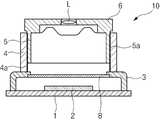
도 1은 종래 카메라 모듈의 분해 사시도이고, 도 2는 종래 카메라 모듈이 개략적으로 도시된 단면도로서, 종래의 카메라 모듈(10)은 CCD나 CMOS의 이미지센서 (2)가 와이어 본딩에 의해서 장착된 프린트기판(1)이 플라스틱 재질의 하우징(3) 하부에 결합되고 상기 하우징(3) 상부로 연장된 경통(4)에 하부로 원통형 몸체(5)가 연장된 배럴(6)이 결합됨에 의해서 제작된다.Figure 1 is an exploded perspective view of a conventional camera module, Figure 2 is a schematic cross-sectional view showing a conventional camera module, the
상기 카메라 모듈(10)은 경통(4) 내주면에 형성된 암나사부(4a)와 원통형 몸체(5)의 외주면에 형성된 숫나사부(5a)의 나사 결합으로 하우징(3)과 배럴(6)이 상호 결합된다.The
이때, 상기 프린트기판(1)의 상면, 즉 배럴(6)의 하단부에 장착된 렌즈(L)와 이미지센서(2) 사이에는 적외선 차단 필터(IR CUT-OFF FILTER:이하 'IR 필터'라 칭함)(8)가 결합됨으로써, 이미지센서(2)로 유입되는 과도한 장파장의 적외선을 차단시키게 된다.In this case, an IR cut-off filter (hereinafter referred to as an 'IR filter') is formed between the upper surface of the printed
상기와 같이 조립된 카메라 모듈은, 특정한 사물로부터 유입되는 빛이 렌즈(L)를 통과하면서 상이 반전되어 이미지센서(2)의 표면에 포커싱되는 데, 이때 나사 결합에 의해서 하우징(3) 상단에 체결된 배럴(6)을 회전시키면서 최적의 포커스가 맞춰진 지점에서 하우징(3)과 배럴(6)의 유격 사이로 접착제를 주입하여 하우징(3)과 배럴(6)을 접착 고정시켜 최종적인 카메라 모듈 제품이 생산된다.In the camera module assembled as described above, light flowing from a specific object passes through the lens L, and the image is inverted to focus on the surface of the
한편, 최근에는 소비자가 요구하는 카메라의 기능적 요소가 점점 높아짐에 따라 오토포커스(A/F) 기능이나 줌(ZOOM) 기능이 적용된 카메라 모듈이 개발되어 휴대폰상에 탑재되고는 있으나, 아직까지는 초점이 고정된 카메라 모듈이 주로 생산되고 있는 바, 종래의 카메라 모듈은 모듈의 조립과 포커싱 공정을 수행하기 위한 배럴(6)과 하우징(3)의 결합이 암, 수 나사부(4a)(5a)의 대응 결합에 의한 회전 구조로 주로 이루어지게 된다.On the other hand, as the functional elements of cameras that consumers demand have increased in recent years, camera modules with an autofocus (A / F) function or a zoom function have been developed and mounted on mobile phones. The fixed camera module is mainly produced. In the conventional camera module, a combination of the
그러나, 상기 배럴(6)의 외주면과 하우징(3)의 내주면상에 암,수 나사부(4a)(5a)를 형성하기 위한 금형 제작이 어려울 뿐만 아니라, 상기 암,수 나사부(4a)(5a)가 소정의 각도로 기울어져 있기 때문에 나사산을 따라 하우징(3)과 배럴(6)의 회전 결합시 렌즈에 대한 광축이 나사산의 기울어진 각도만큼 기울어질 수 밖에 없어 정확한 초점을 맞추기가 어려운 문제점이 있다.However, it is difficult to manufacture a mold for forming the female and
또한, 상기 하우징(3)과 배럴(6)이 수직 결합될 때 암,수 나사부(4a)(5a)가 틀어진 각도로 맞물리게 되면 나사산이 뭉개지거나 암,수 나사부(4a)(5a)의 마찰에 의해 그 결합 부위가 마모되면서 미세한 파티클이 발생됨에 따른 이물 불량이 발생하는 등의 조립성이 현저히 떨어지게 되는 단점이 있다.In addition, when the
따라서, 본 발명은 종래 카메라 모듈의 조립 과정에서 발생되는 상기 제반 단점과 문제점을 해결하기 위하여 창안된 것으로서, 카메라 모듈을 구성하는 하우징과 배럴의 조립이 용이하도록 함과 아울러 포커싱 공정에서 광축에 대하여 수직의 방향으로 초점이 고정되도록 하기 위하여 상기 하우징과 배럴의 내,외주면이 계단식 치합면으로 구성되도록 함으로써, 카메라 모듈의 광축에 대하여 수직 고정됨과 동시에 해상력이 향상될 수 있도록 한 카메라 모듈의 치합 구조가 제공됨에 발명의 목적이 있다.Accordingly, the present invention was devised to solve the above-mentioned disadvantages and problems in the assembly process of the conventional camera module, and facilitates assembly of the housing and the barrel constituting the camera module and is perpendicular to the optical axis in the focusing process. In order to fix the focus in the direction of the inner and outer peripheral surfaces of the housing and the barrel is composed of a stepped mating surface, so that the vertically fixed to the optical axis of the camera module and at the same time the resolution of the camera module is provided to improve the resolution There is an object of the invention.
본 발명의 상기 목적은, 이미지센서가 장착된 기판이 저면에 결합되고 내주면상에 계단식 치합면이 형성된 원통형의 경통이 상부로 연장된 하우징과, 내부에 다단의 렌즈가 장착된 원통형 몸체가 하부로 연장 형성된 배럴로 구성되어, 상기 배럴의 원통형 몸체가 하우징의 경통 내부로 수직 결합되는 카메라모듈의 구조에 의해서 달성된다.The object of the present invention is a housing, the cylindrical barrel is coupled to the bottom surface and the casing is formed on the inner circumferential surface is formed on the inner circumferential surface and the cylindrical body is equipped with a multi-stage lens in the bottom Consisting of the barrel formed to extend, the cylindrical body of the barrel is achieved by the structure of the camera module vertically coupled into the barrel of the housing.
상기 하우징은 원통형의 경통 하부에 배럴의 렌즈로부터 입사되는 장파장의 적외선을 차단시키기 위한 IR 필터가 내장되며, 경통의 내주면 상부에서부터 하부를 향해 다단으로 단턱진 다수의 수평접촉면이 계단식으로 구비된 치합면이 형성되어 있다.The housing has a built-in IR filter for blocking long-wavelength infrared rays incident from the lens of the barrel in the lower portion of the cylindrical barrel, and the haptic surface is provided with a plurality of horizontal contact surface stepped stepwise from the top of the inner circumferential surface of the barrel Is formed.
또한, 상기 배럴은 원판형의 렌즈고정부 하부로 원통형 몸체가 연장 형성되고 상기 원통형 몸체의 외주면상에는 다수의 수평접촉면이 하향 경사지게 단턱진 계단식 치합면이 형성된다.In addition, the barrel is formed with a cylindrical body extending below the disk-shaped lens fixing portion, and a stepped mating surface is formed on the outer peripheral surface of the cylindrical body with a plurality of horizontal contact surface inclined downward.
상기 배럴은 하부의 원통형 몸체가 하우징의 경통 상단 개구부를 통해 삽입되어 각 부재의 내,외주면에 형성된 계단식 치합면의 각 수평접촉면이 서로 대접을 이루어 밀착되고, 상기 배럴의 회전에 의해 각 수평접촉면이 다단으로 밀착 결합됨에 따라 배럴의 렌즈고정부에 장착된 렌즈를 통해 입사되는 광축에 대하여 항상 수직한 방향으로 하우징과 배럴이 결합됨과 동시에 렌즈의 초점 조정이 수행될 수 있도록 함에 기술적 특징이 있다.The barrel has a lower cylindrical body inserted through the upper opening of the barrel of the housing, and the horizontal contact surfaces of the stepped mating surfaces formed on the inner and outer peripheral surfaces of each member are brought into close contact with each other, and the horizontal contact surfaces are rotated by the rotation of the barrel. As a result of close contact with the multi-stage, the housing and the barrel are always coupled in a direction perpendicular to the optical axis incident through the lens mounted on the lens fixing part of the barrel, and at the same time, the focusing of the lens can be performed.
본 발명 카메라 모듈의 치합 구조의 상기 목적에 대한 기술적 구성을 비롯한 작용효과에 관한 사항은 본 발명의 바람직한 실시예가 도시된 도면을 참조한 아래의 상세한 설명에 의해서 명확하게 이해될 것이다.Matters relating to the operational effects including the technical configuration for the above purpose of the tooth structure of the camera module of the present invention will be clearly understood by the following detailed description with reference to the drawings in which preferred embodiments of the present invention are shown.
카메라 모듈의 구조Camera Module Structure
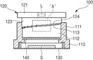
먼저, 도 3은 본 발명에 따른 카메라 모듈의 조립 사시도이고, 도 4는 본 발명에 따른 카메라 모듈의 조립 단면도이며, 도 5는 도 4의 'A' 부분의 확대 단면도이다.First, FIG. 3 is an assembled perspective view of a camera module according to the present invention, FIG. 4 is an assembled cross-sectional view of the camera module according to the present invention, and FIG. 5 is an enlarged cross-sectional view of part 'A' of FIG.
도시된 바와같이, 본 발명에 따른 카메라 모듈(100)은 하부에 이미지센서(S)가 내장된 하우징(110)의 상부로 내주면에 다단의 하부 치합면(112)이 형성된 원통형의 경통(111)이 형성되고, 상기 경통(111)의 상단 개구부를 통해 삽입되며 외주면에 상부 치합면(123)이 구비된 원통형 몸체(122)가 하부로 연장 형성된 배럴(120)로 구성된다.As shown, the
상기 하우징(110)은 그 저면에 이미지센서(S)가 장착된 기판(130)이 결합되고 상기 하우징(110)에 결합된 기판(130)의 저면은 FPCB의 상면에 부착되어 상기 이미지센서(S)에 촬상된 이미지가 FPCB의 회로를 통해 이미지 디스플레이어로 송출되도록 한다.The
또한, 상기 하우징(110)은 상기 이미지센서(S)의 상부측의 경통(111) 내측 하부에 이미지센서(S)로 유입되는 광선중에 포함된 장파장의 적외선을 차단하는 IR 필터(140)가 내장되며, 상기 IR 필터(140)의 상부로는 경통(111)의 내주면을 따라 다단으로 단턱진 계단식의 하부 치합면(112)이 형성된다.In addition, the
상기 경통(111)의 내주면에 형성된 하부 치합면(112)은 경통(111)의 상단 개구부 소정 지점에서 시작되어 다수의 수평접촉면(113)이 다단의 단턱부를 이루며 단계적으로 하향 배치되도록 함으로써, 전체적인 형상이 경통(111)의 내주면을 따라 나선상으로 하향 경사지게 형성된다.The
이때, 상기 다수의 수평접촉면(113)의 양측부는 일방향으로 테이퍼진 경사면(113a)(113b)이 형성되며, 양측부의 경사면(113a)(113b)은 동일한 각도로 하향 또는 상향 경사면으로 이루어진다.At this time, both side portions of the plurality of
한편, 상기 하우징(110)에 결합되는 배럴(120)은 내부 중앙에 렌즈(L)가 장착된 원판형의 렌즈고정부(121) 하부로 연장된 원통형의 몸체(122) 외주면에 다단의 상부 치합면(123)이 형성된다.On the other hand, the
상기 배럴(120)의 상부 치합면(123)은 하우징(110)의 하부 치합면(112)과 동일한 나선 각도를 이루어 원통형 몸체(122)의 외주면상에서 치합면(123)이 상향 경사지게 돌출 형성되며, 상기 상부 치합면(123)의 하부로 다수의 수평접촉면(124)이 다단의 단턱부를 이루며 단계적으로 상향 경사지게 형성된다.The
또한, 상기 상부 치합면(123)의 각 수평접촉부(124)는 양측부로 동일 각도의 경사면(124a)(124b)이 상향 또는 하향 경사지게 형성된다.In addition, the
이와 같이, 상기 상,하부 치합면(112)(123)은 전체적인 형상이 동일한 나선 각도를 이루어 일측으로 경사지도록 다단의 단턱부로 형성되며, 상기 단턱부는 광 축에 대하여 수직 방향의 수평접촉면(113)(124)으로 형성되어 양측부에 소정의 각도로 상향 또는 하향 경사진 경사면(113a,113b)(124a,124b)이 구비됨으로써, 상기 하우징(110)에 배럴(120)을 결합시켜 상기 배럴(120)을 회전시키게 되면, 각 부재(110)(120)에 형성된 치합면(112)(123)의 수평접촉면(113)(124) 양측부에 형성된 상기 수평접촉면(113)(124)이 대접됨과 동시에 각 경사면(113a,113b)(124a,124b)의 미끄럼 접촉에 의해서 상기 하우징(110) 내부의 이미지센서(S)와 상기 배럴(120)에 장착된 렌즈(L)간의 간격 조절이 이루어지게 된다.As such, the upper and
카메라 모듈의 초점 조절 구조Focusing structure of the camera module
상기와 같은 구조로 이루어진 본 발명 카메라 모듈은, 내주면에 하부 치합면(112)이 하향 경사지게 돌출된 경통(111)의 상단 개구부를 통해 외주면에 상부 치합면(123)이 상향 경사지게 돌출 형성된 원통형 몸체(122)가 삽입되어 하우징(110)과 배럴(120)의 결합이 이루어지게 된다.The camera module of the present invention having the structure as described above has a cylindrical body in which the
이때, 상기 경통(111)의 내부에서 치합되는 상,하부 치합면(112)(123)은 각 치합면(112)(123)의 수평접촉면(113)(124)과 경사면(113a,113b)(124a,124b)이 나선상의 계면을 형성하며 맞대어져 밀착 결합되고, 상기 상,하부 치합면(112)(123)이 밀착되도록 상기 배럴(120)은 하우징(110)의 상부에서 수직으로 삽입 장착된다.At this time, the upper and
이와 같이, 상기 하우징(110)과 배럴(120)이 수직 결합되면, 상기 배럴(110)을 광축을 중심으로 회전시켜 카메라 모듈의 초점 조절을 위한 포커싱 공정이 수행되는 데, 상기 배럴(120)을 좌, 우로 회전시켜 하우징(110) 내의 이미지센서(S)와 렌즈(L)간의 간격 조절에 의해 최적의 초점이 조절되도록 한다.As such, when the
여기서, 상기 하우징(110)의 경통(111) 내부에서 치합되는 각 치합면(112)(123)은 나선상의 계면을 중심으로 각 치합면(112)(123)의 수평접촉면(113)(124)을 중심으로 유동되어 각 수평접촉면(113)(124)이 단계적으로 대접됨에 따라 상기 하우징(110)의 경통(111) 내부에서 배럴(120)의 수직 이송이 이루어진다.Here, each of the mating surfaces 112 and 123 to be engaged within the
이때, 상기 수평접촉면(113)(124)의 단계별 접촉은 수평접촉면(113)(124)의 양측부에 형성된 경사면(113a,113b)(124a,124b)의 미끄럼 유동에 의해서 이루어지며, 상기 경사면(113a,113b)(124a,124b)은 상기 배럴(120)을 시계 방향 또는 반시계 방향으로 회전시킬 때 상기 수평접촉면(113)(124)의 원할한 이송이 가능하도록 수평접촉면(113)(124)에 대하여 둔각을 이루어 단턱지게 절곡 형성된다.At this time, the step-wise contact of the
또한, 상기 경사면(113a,113b)(124a,124b)의 경사 각도는 상기 배럴(120)을 반시계 방향으로 회전시킬 때 상부 수평접촉면(124)을 연결하는 경사면(124a,124b)이 하부 수평접촉면(113)을 연결하는 경사면(113a,113b)이 접촉된 상태에서 각 수평접촉면(113)(124)과 경사면(113a,113b)(124a,124b)이 형성하는 절곡부를 자연스럽게 타고 넘어갈 수 있는 소정의 각도로 형성됨이 바람직할 것이다.In addition, the inclination angles of the
이와 같은 구조의 본 발명은, 하우징(110)의 상부에 배럴(120)을 수직으로 삽입하여 두 부재(110)(120)가 광축에 대하여 수직을 이루도록 한 후에 상기 배럴(120)을 시계 방향 또는 반시계 방향을 회전시켜 하우징(110)의 경통(111)과 배럴(120)의 몸체(122) 사이에서 치합되는 상,하부 치합면(112)(123)의 각 수평접촉면 (113)(124)이 단계적으로 대접됨에 따른 배럴(120)의 높이 조절에 의해서 카메라 모듈의 포커싱 공정이 수행됨과 동시에 광축에 대하여 항상 수직한 방향으로 카메라 모듈이 조립될 수 있도록 함에 기술적 특징이 있으며, 상기의 포커싱 공정을 통해 최적의 포커스가 맞춰진 지점에서 하우징(110)과 배럴(120)의 접촉면 사이로 접착제를 주입하여 하우징(110)과 배럴(120)을 접착 고정시킴으로써, 최종적인 카메라 모듈 제품의 생산이 완료된다.According to the present invention, the
이상의 본 발명은 상기에 기술된 기술적 구성에만 한정되지 않고, 당업자들에 의해 구조적으로 다양한 변형과 변경이 있을 수 있으며, 이는 첨부된 특허청구범위에서 정의되는 본 발명의 취지와 범위에 포함되는 것으로 보아야 할 것이다.The present invention is not limited to the above-described technical configuration, but may be structurally various modifications and changes by those skilled in the art, which should be considered to be included in the spirit and scope of the present invention as defined in the appended claims. something to do.
이상에서 설명한 바와같이, 본 발명 카메라 모듈의 치합 구조는 카메라 모듈을 구성하는 하우징의 경통 내주면과 배럴의 원통형 몸체 외주면에 각각 형성된 상,하부 치합면의 대응 결합에 의해서 하우징과 배럴이 광축에 대하여 항상 수직으로 결합됨으로써, 광축의 기울어짐이 방지되는 이점이 있음과 아울러 상기 배럴의 회전에 의한 초점 조절 시 광축의 틀어짐이 방지됨에 따라 용이한 포커스 조절과 해상력이 향상되는 장점이 있다.As described above, the coupling structure of the camera module of the present invention is always connected to the optical axis by the housing and the barrel by the corresponding coupling between the inner circumferential surface of the housing constituting the camera module and the upper and lower engagement surfaces respectively formed on the outer circumferential surface of the cylindrical body of the barrel. By being vertically coupled, there is an advantage that the tilt of the optical axis is prevented, and the focusing and resolution are easily improved as the optical axis is prevented from shifting when the focus is adjusted by the rotation of the barrel.
Claims (8)
Translated fromKoreanPriority Applications (1)
| Application Number | Priority Date | Filing Date | Title |
|---|---|---|---|
| KR1020050094821AKR100738391B1 (en) | 2005-10-10 | 2005-10-10 | Joint structure of the camera module |
Applications Claiming Priority (1)
| Application Number | Priority Date | Filing Date | Title |
|---|---|---|---|
| KR1020050094821AKR100738391B1 (en) | 2005-10-10 | 2005-10-10 | Joint structure of the camera module |
Publications (2)
| Publication Number | Publication Date |
|---|---|
| KR20070039680A KR20070039680A (en) | 2007-04-13 |
| KR100738391B1true KR100738391B1 (en) | 2007-07-12 |
Family
ID=38160375
Family Applications (1)
| Application Number | Title | Priority Date | Filing Date |
|---|---|---|---|
| KR1020050094821AExpired - Fee RelatedKR100738391B1 (en) | 2005-10-10 | 2005-10-10 | Joint structure of the camera module |
Country Status (1)
| Country | Link |
|---|---|
| KR (1) | KR100738391B1 (en) |
Cited By (2)
| Publication number | Priority date | Publication date | Assignee | Title |
|---|---|---|---|---|
| KR100867511B1 (en) | 2007-06-20 | 2008-11-10 | 삼성전기주식회사 | Camera module |
| KR20150033099A (en)* | 2013-09-23 | 2015-04-01 | 엘지이노텍 주식회사 | Camera Module |
Families Citing this family (2)
| Publication number | Priority date | Publication date | Assignee | Title |
|---|---|---|---|---|
| KR101018808B1 (en)* | 2009-08-06 | 2011-03-03 | 삼성전기주식회사 | Camera module |
| KR102222820B1 (en)* | 2014-06-23 | 2021-03-04 | 삼성전자 주식회사 | Auto focus camera module and electronic device comprising the same |
Citations (2)
| Publication number | Priority date | Publication date | Assignee | Title |
|---|---|---|---|---|
| KR20040084989A (en)* | 2003-03-28 | 2004-10-07 | 샤프 가부시키가이샤 | Module for optical device, and manufacturing method therefor |
| KR20050082759A (en)* | 2004-02-20 | 2005-08-24 | 삼성테크윈 주식회사 | Image sensor module and camera module package therewith |
- 2005
- 2005-10-10KRKR1020050094821Apatent/KR100738391B1/ennot_activeExpired - Fee Related
Patent Citations (2)
| Publication number | Priority date | Publication date | Assignee | Title |
|---|---|---|---|---|
| KR20040084989A (en)* | 2003-03-28 | 2004-10-07 | 샤프 가부시키가이샤 | Module for optical device, and manufacturing method therefor |
| KR20050082759A (en)* | 2004-02-20 | 2005-08-24 | 삼성테크윈 주식회사 | Image sensor module and camera module package therewith |
Cited By (3)
| Publication number | Priority date | Publication date | Assignee | Title |
|---|---|---|---|---|
| KR100867511B1 (en) | 2007-06-20 | 2008-11-10 | 삼성전기주식회사 | Camera module |
| KR20150033099A (en)* | 2013-09-23 | 2015-04-01 | 엘지이노텍 주식회사 | Camera Module |
| KR102121296B1 (en)* | 2013-09-23 | 2020-06-10 | 엘지이노텍 주식회사 | Camera Module |
Also Published As
| Publication number | Publication date |
|---|---|
| KR20070039680A (en) | 2007-04-13 |
Similar Documents
| Publication | Publication Date | Title |
|---|---|---|
| KR100833312B1 (en) | Camera module | |
| JP5680347B2 (en) | Aspheric plastic lens and mold for manufacturing the same | |
| KR100816844B1 (en) | Image sensor module and manufacturing method thereof and camera module including same | |
| KR20100018405A (en) | Camera module and method for manufacturing the same | |
| US20080165427A1 (en) | Image capturing device | |
| KR20090047307A (en) | Camera module and its manufacturing method | |
| KR20100018407A (en) | Camera module and method for manufacturing the same | |
| KR100803244B1 (en) | Camera module | |
| KR100826270B1 (en) | How to adjust the focus of the camera module | |
| KR100738391B1 (en) | Joint structure of the camera module | |
| CN101876741B (en) | Focusing lens module | |
| KR100891177B1 (en) | Camera module | |
| KR101008475B1 (en) | Camera module | |
| KR100769725B1 (en) | Dual camera module | |
| KR100808017B1 (en) | Camera module | |
| KR101771775B1 (en) | Camera module | |
| KR100863797B1 (en) | Camera module | |
| KR20090078475A (en) | Camera module | |
| KR20080028588A (en) | Camera module and its assembly method | |
| KR100716789B1 (en) | Camera module | |
| KR100885505B1 (en) | Camera module and its manufacturing method | |
| KR101353168B1 (en) | Chip on glass and camera module having the same | |
| KR20090055978A (en) | Camera module to prevent foreign objects from entering | |
| KR101310579B1 (en) | Camera Module | |
| KR100829980B1 (en) | Camera module |
Legal Events
| Date | Code | Title | Description |
|---|---|---|---|
| A201 | Request for examination | ||
| PA0109 | Patent application | St.27 status event code:A-0-1-A10-A12-nap-PA0109 | |
| PA0201 | Request for examination | St.27 status event code:A-1-2-D10-D11-exm-PA0201 | |
| R17-X000 | Change to representative recorded | St.27 status event code:A-3-3-R10-R17-oth-X000 | |
| E902 | Notification of reason for refusal | ||
| PE0902 | Notice of grounds for rejection | St.27 status event code:A-1-2-D10-D21-exm-PE0902 | |
| PG1501 | Laying open of application | St.27 status event code:A-1-1-Q10-Q12-nap-PG1501 | |
| R18-X000 | Changes to party contact information recorded | St.27 status event code:A-3-3-R10-R18-oth-X000 | |
| E701 | Decision to grant or registration of patent right | ||
| PE0701 | Decision of registration | St.27 status event code:A-1-2-D10-D22-exm-PE0701 | |
| GRNT | Written decision to grant | ||
| PR0701 | Registration of establishment | St.27 status event code:A-2-4-F10-F11-exm-PR0701 | |
| PR1002 | Payment of registration fee | St.27 status event code:A-2-2-U10-U11-oth-PR1002 Fee payment year number:1 | |
| PG1601 | Publication of registration | St.27 status event code:A-4-4-Q10-Q13-nap-PG1601 | |
| G170 | Re-publication after modification of scope of protection [patent] | ||
| PG1701 | Publication of correction | St.27 status event code:A-5-5-P10-P19-oth-PG1701 Patent document republication publication date:20080422 Republication note text:Request for Correction Notice (Document Request) Gazette number:1007383910000 Gazette reference publication date:20070712 | |
| LAPS | Lapse due to unpaid annual fee | ||
| PC1903 | Unpaid annual fee | St.27 status event code:A-4-4-U10-U13-oth-PC1903 Not in force date:20100706 Payment event data comment text:Termination Category : DEFAULT_OF_REGISTRATION_FEE | |
| PC1903 | Unpaid annual fee | St.27 status event code:N-4-6-H10-H13-oth-PC1903 Ip right cessation event data comment text:Termination Category : DEFAULT_OF_REGISTRATION_FEE Not in force date:20100706 | |
| R18-X000 | Changes to party contact information recorded | St.27 status event code:A-5-5-R10-R18-oth-X000 | |
| P22-X000 | Classification modified | St.27 status event code:A-4-4-P10-P22-nap-X000 | |
| R18-X000 | Changes to party contact information recorded | St.27 status event code:A-5-5-R10-R18-oth-X000 | |
| P22-X000 | Classification modified | St.27 status event code:A-4-4-P10-P22-nap-X000 |