KR100733939B1 - Photosensitive resin composition, ink-jet recording head using the composition, and production method for the same - Google Patents
Photosensitive resin composition, ink-jet recording head using the composition, and production method for the sameDownload PDFInfo
- Publication number
- KR100733939B1 KR100733939B1KR1020057024097AKR20057024097AKR100733939B1KR 100733939 B1KR100733939 B1KR 100733939B1KR 1020057024097 AKR1020057024097 AKR 1020057024097AKR 20057024097 AKR20057024097 AKR 20057024097AKR 100733939 B1KR100733939 B1KR 100733939B1
- Authority
- KR
- South Korea
- Prior art keywords
- ink
- substrate
- recording head
- flow path
- resin composition
- Prior art date
- Legal status (The legal status is an assumption and is not a legal conclusion. Google has not performed a legal analysis and makes no representation as to the accuracy of the status listed.)
- Expired - Fee Related
Links
Images


Classifications
- G—PHYSICS
- G03—PHOTOGRAPHY; CINEMATOGRAPHY; ANALOGOUS TECHNIQUES USING WAVES OTHER THAN OPTICAL WAVES; ELECTROGRAPHY; HOLOGRAPHY
- G03F—PHOTOMECHANICAL PRODUCTION OF TEXTURED OR PATTERNED SURFACES, e.g. FOR PRINTING, FOR PROCESSING OF SEMICONDUCTOR DEVICES; MATERIALS THEREFOR; ORIGINALS THEREFOR; APPARATUS SPECIALLY ADAPTED THEREFOR
- G03F7/00—Photomechanical, e.g. photolithographic, production of textured or patterned surfaces, e.g. printing surfaces; Materials therefor, e.g. comprising photoresists; Apparatus specially adapted therefor
- G03F7/004—Photosensitive materials
- G03F7/038—Macromolecular compounds which are rendered insoluble or differentially wettable
- B—PERFORMING OPERATIONS; TRANSPORTING
- B41—PRINTING; LINING MACHINES; TYPEWRITERS; STAMPS
- B41J—TYPEWRITERS; SELECTIVE PRINTING MECHANISMS, i.e. MECHANISMS PRINTING OTHERWISE THAN FROM A FORME; CORRECTION OF TYPOGRAPHICAL ERRORS
- B41J2/00—Typewriters or selective printing mechanisms characterised by the printing or marking process for which they are designed
- B41J2/005—Typewriters or selective printing mechanisms characterised by the printing or marking process for which they are designed characterised by bringing liquid or particles selectively into contact with a printing material
- B41J2/01—Ink jet
- B41J2/135—Nozzles
- B41J2/16—Production of nozzles
- B41J2/1621—Manufacturing processes
- B41J2/1631—Manufacturing processes photolithography
- B—PERFORMING OPERATIONS; TRANSPORTING
- B41—PRINTING; LINING MACHINES; TYPEWRITERS; STAMPS
- B41J—TYPEWRITERS; SELECTIVE PRINTING MECHANISMS, i.e. MECHANISMS PRINTING OTHERWISE THAN FROM A FORME; CORRECTION OF TYPOGRAPHICAL ERRORS
- B41J2/00—Typewriters or selective printing mechanisms characterised by the printing or marking process for which they are designed
- B41J2/005—Typewriters or selective printing mechanisms characterised by the printing or marking process for which they are designed characterised by bringing liquid or particles selectively into contact with a printing material
- B41J2/01—Ink jet
- B41J2/135—Nozzles
- B41J2/16—Production of nozzles
- B41J2/1601—Production of bubble jet print heads
- B41J2/1603—Production of bubble jet print heads of the front shooter type
- B—PERFORMING OPERATIONS; TRANSPORTING
- B41—PRINTING; LINING MACHINES; TYPEWRITERS; STAMPS
- B41J—TYPEWRITERS; SELECTIVE PRINTING MECHANISMS, i.e. MECHANISMS PRINTING OTHERWISE THAN FROM A FORME; CORRECTION OF TYPOGRAPHICAL ERRORS
- B41J2/00—Typewriters or selective printing mechanisms characterised by the printing or marking process for which they are designed
- B41J2/005—Typewriters or selective printing mechanisms characterised by the printing or marking process for which they are designed characterised by bringing liquid or particles selectively into contact with a printing material
- B41J2/01—Ink jet
- B41J2/135—Nozzles
- B41J2/16—Production of nozzles
- B41J2/1621—Manufacturing processes
- B41J2/1626—Manufacturing processes etching
- B—PERFORMING OPERATIONS; TRANSPORTING
- B41—PRINTING; LINING MACHINES; TYPEWRITERS; STAMPS
- B41J—TYPEWRITERS; SELECTIVE PRINTING MECHANISMS, i.e. MECHANISMS PRINTING OTHERWISE THAN FROM A FORME; CORRECTION OF TYPOGRAPHICAL ERRORS
- B41J2/00—Typewriters or selective printing mechanisms characterised by the printing or marking process for which they are designed
- B41J2/005—Typewriters or selective printing mechanisms characterised by the printing or marking process for which they are designed characterised by bringing liquid or particles selectively into contact with a printing material
- B41J2/01—Ink jet
- B41J2/135—Nozzles
- B41J2/16—Production of nozzles
- B41J2/1621—Manufacturing processes
- B41J2/1637—Manufacturing processes molding
- B41J2/1639—Manufacturing processes molding sacrificial molding
- G—PHYSICS
- G03—PHOTOGRAPHY; CINEMATOGRAPHY; ANALOGOUS TECHNIQUES USING WAVES OTHER THAN OPTICAL WAVES; ELECTROGRAPHY; HOLOGRAPHY
- G03F—PHOTOMECHANICAL PRODUCTION OF TEXTURED OR PATTERNED SURFACES, e.g. FOR PRINTING, FOR PROCESSING OF SEMICONDUCTOR DEVICES; MATERIALS THEREFOR; ORIGINALS THEREFOR; APPARATUS SPECIALLY ADAPTED THEREFOR
- G03F7/00—Photomechanical, e.g. photolithographic, production of textured or patterned surfaces, e.g. printing surfaces; Materials therefor, e.g. comprising photoresists; Apparatus specially adapted therefor
- G03F7/004—Photosensitive materials
- G03F7/038—Macromolecular compounds which are rendered insoluble or differentially wettable
- G03F7/0387—Polyamides or polyimides
Landscapes
- Engineering & Computer Science (AREA)
- Manufacturing & Machinery (AREA)
- Physics & Mathematics (AREA)
- Spectroscopy & Molecular Physics (AREA)
- General Physics & Mathematics (AREA)
- Particle Formation And Scattering Control In Inkjet Printers (AREA)
- Polyamides (AREA)
- Compositions Of Macromolecular Compounds (AREA)
- Ink Jet Recording Methods And Recording Media Thereof (AREA)
- Macromonomer-Based Addition Polymer (AREA)
Abstract
Translated fromKorean
Description
Translated fromKorean본 발명은 신규한 감광성 수지 조성물에 관한 것이다. 또한 본 발명은 상기 감광성 수지 조성물을 사용한 잉크젯 기록 헤드 및 그의 제조 방법에 관한 것이며, 특히 잉크를 토출하기 위한 압력 발생 소자가 형성된 기판과, 상기 기판과 접합하여 잉크 유로를 형성하기 위한 유로 형성 부재와의 밀착력의 향상 방법, 및 상기 기판을 관통하여 잉크 유로에 잉크를 공급하기 위한 잉크 공급구의 형성 방법에 관한 것이다.The present invention relates to a novel photosensitive resin composition. The present invention also relates to an inkjet recording head using the photosensitive resin composition and a manufacturing method thereof, and in particular, a substrate on which a pressure generating element for ejecting ink is formed, and a flow path forming member for joining the substrate to form an ink flow path; And a method of forming an ink supply port for supplying ink to an ink passage through the substrate.
종래, 잉크젯 기록 헤드의 제조 방법, 및 잉크 토출 압력 발생 소자가 형성된 기판과 접합하여 액로를 형성하는 액로 형성 부재에 대해서는 다양한 제안이 이루어지고 있다. 일본 특허 공개 (소)57-208255호, 동 (소)57-208256호 공보에는, 잉크 토출 압력 발생 소자가 형성된 기판 상에 감광성 수지로 액로 패턴을 형성하고, 유리 등으로 이루어진 상부판을 기판과 접합하고, 조립체를 절단함으로써 잉크젯 기록 헤드를 제조하는 방법이 개시되어 있다.Background Art Conventionally, various proposals have been made for a method of manufacturing an inkjet recording head and a liquid passage forming member that forms a liquid passage by bonding to a substrate on which an ink discharge pressure generating element is formed. Japanese Patent Laid-Open Nos. 57-208255 and 57-208256 disclose that a liquid path pattern is formed of photosensitive resin on a substrate on which an ink discharge pressure generating element is formed, and an upper plate made of glass or the like is attached to the substrate. A method of manufacturing an inkjet recording head by bonding and cutting an assembly is disclosed.
또한, 문헌 [Hewlett-Packard Journal 36, 5 (1985)]에서는 잉크 토출 압력 발생 소자가 형성된 기판 상에 감광성 수지로 액로 패턴을 형성하고, Ni 전기 주조에 의해 제조한 오리피스 플레이트를 기판과 접합시킴으로써 잉크젯 기록 헤드를 제조하는 방법이 개시되어 있다.In addition, Hewlett-Packard Journal 36, 5 (1985) describes an inkjet by forming a liquid path pattern with a photosensitive resin on a substrate on which an ink discharge pressure generating element is formed, and joining an orifice plate manufactured by Ni electroforming with a substrate. A method of manufacturing a recording head is disclosed.
또한 일본 특허 공개 (소)61-154947호에는, 잉크 토출 압력 발생 소자가 형성된 기판의 잉크 토출 압력 발생 소자 상에 용해 가능한 수지로 액로 패턴을 형성하고, 상기 패턴을 에폭시 수지 등으로 코팅, 경화하고, 기판 절단 후에 용해 가능한 수지를 용출하여 잉크젯 기록 헤드를 제조하는 방법이 개시되어 있다.In Japanese Patent Laid-Open No. 61-154947, a liquid channel pattern is formed of a resin soluble in an ink discharge pressure generating element of a substrate on which an ink discharge pressure generating element is formed, and the pattern is coated and cured with an epoxy resin or the like. A method of producing an inkjet recording head by eluting a resin that can be dissolved after substrate cutting is disclosed.
또한 일본 특허 공개 (평)3-184868호에는, 상기한 일본 특허 공개 (소)61-154947호에 기재된 잉크젯 기록 헤드의 제조에 최적인 코팅 수지 조성물로서 방향족 에폭시 화합물의 양이온 중합 경화물이 유용하다고 개시되어 있다.In addition, Japanese Patent Laid-Open No. Hei 3-184868 discloses that a cationic polymerization cured product of an aromatic epoxy compound is useful as a coating resin composition suitable for the production of the inkjet recording head described in the above-mentioned Japanese Patent Laid-Open No. 61-154947. Is disclosed.
상술한 어떤 방법에서든, 잉크 토출 압력 발생 소자가 형성된 기판과 액로 형성 부재의 접합 강도는 기본적으로 액로 형성 부재가 되는 수지 재료(감광성 수지층, 코팅 수지층)의 밀착력에 의존하고 있다.In any of the above-described methods, the bonding strength between the substrate on which the ink discharge pressure generating element is formed and the liquid flow forming member is basically dependent on the adhesion of the resin material (photosensitive resin layer, coating resin layer) to be the liquid flow forming member.
또한 상술한 어떤 구성에서든, 헤드에 잉크를 공급하기 위한 잉크 공급계를 부착할 필요가 있다. 여기서, 잉크의 토출구가 압력 발생 소자에 대향하여 설치된 구조를 갖는 소위 사이드 슈터(side shooter) 타입의 잉크젯 기록 헤드에서는, 지지 기판에 관통 구멍을 형성하여 지지 기판의 이면으로부터 잉크를 공급하는 구조가 일반적으로 알려져 있다. 이러한 잉크젯 기록 헤드의 제조 방법의 알려진 예는, 미국 특허 제5,478,606호에 기재된 바와 같이, (1) 잉크 토출 압력 발생 소자가 형성된 기판 상에 용해 가능한 수지로 잉크 유로 패턴을 형성하는 단계, (2) 고 상 에폭시 수지를 함유하는 코팅 수지를 실온에서 용매에 용해시키고, 얻어진 용액을 용해 가능한 수지층에 용매 코팅하여, 용해 가능한 수지층 상에 잉크 유로벽이 되는 액로 형성 부재로서 코팅 수지층을 형성하는 단계, (3) 잉크 토출 압력 발생 소자 위에 코팅층 상의 잉크 토출구를 형성하는 단계, 및 (4) 용해 가능한 수지층을 용출하는 단계를 포함한다.Also in any of the above configurations, it is necessary to attach an ink supply system for supplying ink to the head. Here, in a so-called side shooter type inkjet recording head having a structure in which the ejection openings of the ink are opposed to the pressure generating element, a structure in which through holes are formed in the support substrate to supply ink from the back surface of the support substrate is generally used. Known as Known examples of such a method of manufacturing an inkjet recording head include (1) forming an ink flow path pattern with a resin soluble on a substrate on which an ink discharge pressure generating element is formed, (2) A coating resin containing a solid epoxy resin is dissolved in a solvent at room temperature, and the resulting solution is solvent coated on a soluble resin layer to form a coating resin layer as a liquid formation member that becomes an ink flow path wall on the soluble resin layer. (3) forming an ink discharge port on the coating layer on the ink discharge pressure generating element, and (4) eluting a soluble resin layer.
<발명이 이루고자 하는 기술적 과제><Technical problem to be achieved>
잉크 토출 압력 발생 소자로서 발열 저항체를 사용하고, 잉크의 막 비등에 의한 버블 형성을 이용하여 잉크를 토출시키는 소위 버블젯 기록 헤드의 경우, 잉크에 의한 전기 부식이나 버블 소포시의 공동 현상에 의한 손상을 저감하기 위해서, 발열 저항체 상에는 SiN이나 SiO2라는 무기 절연층과 Ta 등의 반공동화층을 설치하는 것이 일반적이다. 그러나, Ta막은 상술한 액로 형성 부재가 되는 수지 재료와의 밀착력이 매우 낮기 때문에, Ta막으로부터 액로 형성 부재가 박리된다는 문제가 발생하는 경우가 있다.In the case of a so-called bubble jet recording head which uses a heat generating resistor as an ink ejection pressure generating element and ejects ink by using bubble formation by film boiling of ink, damage caused by electrocorrosion by ink or cavitation at the time of bubble defoaming In order to reduce the pressure, an inorganic insulating layer such as SiN or SiO2 and a semi-cavitation layer such as Ta are generally provided on the heat generating resistor. However, since the Ta film has a very low adhesion force with the resin material serving as the above-mentioned liquid forming member, there is a problem that the liquid forming member is peeled off from the Ta film.
이 문제를 회피하기 위해서, 액로 형성 부재가 되는 수지 재료의 밀착력을 향상시킬 목적으로, 액로 형성 부재가 되는 수지 재료가 설치되는 부분의 Ta막을 제거하는 것을 생각할 수 있지만, 이 경우 기판 상의 전기 열 변환체를 포함하는 잉크 토출 압력 발생 소자에 접속하는 전극이 배치된 부분에는 상술한 무기 절연층만을 개재시켜 액로 형성 부재를 구성하는 수지 재료가 적층된다. SiN이나 SiO2라는 무기 절연층은 통상 다공성 막 재료이기 때문에, 수지 중에 함유되는 이온이 무 기 절연층을 투과하여, 이 이온에 의해서 전극이 부식되어 버릴 가능성이 있다.In order to avoid this problem, it is conceivable to remove the Ta film of the portion where the resin material serving as the liquid forming member is provided for the purpose of improving the adhesion of the resin material serving as the liquid forming member. The resin material constituting the liquid passage forming member is laminated on the portion where the electrode connected to the ink discharge pressure generating element including the sieve is disposed, with only the inorganic insulating layer described above. Since the inorganic insulating layer such as SiN or SiO2 is usually a porous membrane material, ions contained in the resin may penetrate the inorganic insulating layer and the electrode may be corroded by the ions.
또한, 잉크 토출 압력 발생 소자가 형성된 기판과 액로 형성 부재의 밀착력 향상을 위해, 기판에 실란 커플링 처리를 실시하거나, 폴리이미드(예를 들면, 상품명: 포토니스(PHOTONEECE), 도레이 인더스트리사(Toray Industries) 제조)를 포함하는 언더코트(밀착력 향상 및 패시베이션층)를 사용하는 예가 알려져 있다.In addition, in order to improve adhesion between the substrate on which the ink discharge pressure generating element is formed and the liquid-forming member, a silane coupling treatment may be performed on the substrate, or a polyimide (for example, PHOTONEECE, Toray Industries, Ltd.) may be used. It is known to use an undercoat (adhesive strength improvement and passivation layer) containing (manufactured by Industries).
잉크젯 기록 헤드는 통상 그 사용 환경하에서 잉크와 항상 접촉하고 있는 부분을 갖지만, 잉크의 영향으로 인해, 토출 압력 발생 소자가 형성된 기판과 액로 형성 부재가 박리하는 것은 피해야 한다. 한편, 최근의 잉크젯 기록 방식에 대해서는 용지 선택성, 화상의 내수성 등의 요구가 높아지고 있고, 이러한 요구에 대응하기 위해서 잉크의 pH를 알칼리측으로 하는 것이 검토되고 있다. 이러한 알칼리성 잉크에 대해서는 잉크 토출 압력 발생 소자가 형성된 기판과 액로 형성 부재의 밀착력을 장기간에 걸쳐 유지하는 것이 곤란한 경우가 있다.The inkjet recording head usually has a portion which is always in contact with the ink under its use environment, but due to the influence of the ink, it is to be avoided that the liquid-forming member and the substrate on which the discharge pressure generating element is formed are peeled off. On the other hand, in recent inkjet recording systems, demands for paper selectivity, water resistance of images, and the like are increasing, and in order to cope with such demands, it is considered to make the pH of the ink alkaline. For such alkaline inks, it may be difficult to maintain the adhesion between the substrate on which the ink discharge pressure generating element is formed and the liquid passage forming member for a long time.
상술한 바를 고려하여, 본 발명의 발명자들은 미국 특허 제6,390,606호에서 폴리에테르아미드 수지로 이루어지는 밀착층을 개재시켜, 잉크 토출 압력 발생 소자가 형성된 기판과 액로 형성 부재를 접합하는 방법을 제안하였다. 이에 따라, 알칼리성 잉크에 대해서도 장기간에 걸쳐 우수한 밀착력을 유지할 수 있으며, 접착면에 Ta 등의 금속면이 노출되고 있는 경우에도 장기간에 걸쳐 우수한 밀착력을 유지할 수 있는 신뢰성이 높은 잉크젯 기록 헤드를 제공할 수 있다는 것을 발견하였다.In view of the above, the inventors of the present invention proposed a method of bonding a liquid-forming member to a substrate on which an ink discharge pressure generating element is formed by interposing an adhesion layer made of a polyetheramide resin in US Pat. No. 6,390,606. As a result, excellent adhesion can be maintained over alkaline ink for a long time, and a highly reliable inkjet recording head capable of maintaining good adhesion for a long time even when a metal surface such as Ta is exposed on the adhesive surface can be provided. I found it.
또한, 기판에 잉크 공급구가 되는 관통 구멍을 형성하는 방법으로는, 절삭, 샌드 블러스트(sand blast), 레이저 가공, 습식 에칭 등 다양한 방법이 시도되고 있다. 그러나, 절삭, 샌드 블러스트, 레이저 가공 등의 방법은 기판이나 각 구성 부재에 대한 손상이 크고, 최악의 경우에는 가공시에 기판이 파손될 수 있다는 문제가 발생한다.In addition, various methods, such as cutting, sand blast, laser processing, and wet etching, have been tried as a method of forming the through hole which becomes an ink supply port in a board | substrate. However, methods such as cutting, sand blasting, laser processing, etc., cause a great damage to the substrate and the respective constituent members, and in the worst case, the substrate may be broken during processing.
기판에 기계적인 힘을 가하지 않고 관통 구멍을 형성하는 방법으로서 습식 에칭이 있다. 본 발명의 발명자들은 미국 특허 제6,379,571호에서 기판으로서 실리콘 기판을 사용하고, 무기 유전체막과 폴리에테르아미드 수지를 마스크로 사용하고, 알칼리성 에칭제를 사용하여 실리콘에 이방성 에칭을 실시함으로써 잉크 공급구를 형성하는 방법을 제안하였다. 이 방법에 따르면, 기판에 기계적인 힘을 가하지 않고 관통 구멍을 형성할 수 있다.Wet etching is a method of forming through holes without applying mechanical force to the substrate. The inventors of the present invention, in US Pat. No. 6,379,571, use an silicon substrate as a substrate, use an inorganic dielectric film and a polyetheramide resin as a mask, and perform anisotropic etching on silicon using an alkaline etching agent to provide an ink supply port. A method of forming was proposed. According to this method, the through hole can be formed without applying a mechanical force to the substrate.
이와 같이, 폴리에테르아미드 수지는 내알칼리성이 우수하기 때문에, 알칼리성 잉크에 접하는 잉크젯 기록 헤드의 구성 재료로서, 또한 알칼리성 에칭제를 사용한 습식 에칭시의 마스크재로서 우수한 재료이다. 그러나, 상술한 용도로 사용되는 폴리에테르아미드 수지는 한층 더 개선이 요구되고 있다. 자세하게는, 폴리에테르아미드 수지는 그 자체로서는 감광성을 갖고 있지 않기 때문에, 폴리에테르아미드 수지를 패턴화하는 경우에는 포토레지스트를 패턴화하여 마스크재를 형성하고, 에칭에 의해 패턴화를 행할 필요가 있다. 또한, 폴리에테르아미드 수지는 습식 에칭이 곤란하기 때문에, 건식 에칭을 행해야 하므로, 공정이 길어짐과 동시에, 대규모 설비가 필요해진다.Thus, since polyetheramide resin is excellent in alkali resistance, it is a material excellent as a constituent material of the inkjet recording head which contacts alkaline ink, and also as a mask material at the time of wet etching using an alkaline etching agent. However, further improvement is required for the polyetheramide resin used for the above-mentioned uses. In detail, since polyetheramide resin does not have photosensitivity in itself, when patterning a polyetheramide resin, it is necessary to pattern a photoresist to form a mask material, and to pattern by etching. . In addition, since the polyetheramide resin is difficult to be wet etched, dry etching must be performed, so that the process becomes long and large-scale equipment is required.
본 발명은 상기 여러 가지 사항을 감안하여 이루어진 것이고, 잉크젯 용도에 바람직한 감광성 수지 조성물을 제공함으로써, 신뢰성이 높은 잉크젯 기록 헤드를 간편한 방법으로 제공하는 것이다.This invention is made | formed in view of the said various matter, and provides a highly reliable inkjet recording head by a simple method by providing the photosensitive resin composition suitable for inkjet uses.
본 발명의 일 측면에 따르면, 감광성 수지 조성물은 하기 화학식 1로 표시되는 반복 단위를 갖는 폴리에테르아미드 수지와, 광 조사에 의해 산을 발생하는 화합물과, 산성 조건하에서 작용하는 상기 폴리에테르아미드 수지용 가교제를 포함한다.According to one aspect of the present invention, the photosensitive resin composition is a polyetheramide resin having a repeating unit represented by the following formula (1), a compound which generates an acid by light irradiation, and the polyetheramide resin for working under acidic conditions Crosslinking agents.

감광성 수지 조성물의 다른 측면에서, 폴리에테르아미드 수지용 가교제가 축합성 멜라민 화합물 또는 축합성 우레아 화합물이고, 축합성 멜라민 화합물이 하기 화학식 2로 표시되는 멜라민 화합물 및(또는) 그의 축합물이며, 축합성 멜라민 화합물이 헥사메톡시메틸 멜라민의 단량체를 90 중량% 이상 함유한다.In another aspect of the photosensitive resin composition, the crosslinking agent for polyetheramide resin is a condensable melamine compound or a condensable urea compound, and the condensable melamine compound is a melamine compound represented by the following formula (2) and / or a condensate thereof, and is condensable The melamine compound contains at least 90% by weight of monomers of hexamethoxymethyl melamine.

본 발명의 다른 측면에 따르면, 잉크젯 기록 헤드는 잉크를 토출하기 위한 토출구와, 상기 토출구에 연통하는 잉크 액로와, 상기 토출구로부터 잉크를 토출시키기 위한 압력을 발생하는 압력 발생 소자가 형성된 기판과, 상기 기판과 접합하여 상기 잉크 유로를 형성하는 잉크 유로 형성 부재를 포함하며,According to another aspect of the present invention, an ink jet recording head includes: a substrate on which an ejection opening for ejecting ink, an ink passage communicating with the ejection opening, a pressure generating element for generating pressure for ejecting ink from the ejection opening, An ink flow path forming member bonded to a substrate to form the ink flow path,
상기 잉크 유로 형성 부재는 상기 화학식 1로 표시되는 구성 단위를 갖는 폴리에테르아미드 수지와, 광 조사에 의해 산을 발생하는 화합물과, 산성 조건하에서 작용하는 상기 폴리에테르아미드 수지용 가교제를 포함하는 감광성 수지 조성물의 경화물층을 개재시켜 상기 기판에 접합되어 있다.The ink flow path forming member is a photosensitive resin comprising a polyetheramide resin having a structural unit represented by the general formula (1), a compound which generates an acid by light irradiation, and a crosslinking agent for the polyetheramide resin that operates under acidic conditions. It is bonded to the said board | substrate through the hardened | cured material layer of a composition.
잉크젯 기록 헤드의 다른 측면에서, 잉크 유로 형성 부재는 에폭시 수지의 양이온 중합 화합물에 의해 형성되고, 잉크를 토출하기 위한 토출구는 압력 발생 소자와 대향하는 측에 설치되어 있으며, 토출 압력 발생 소자는 전기 열 변환체를 포함한다.On the other side of the inkjet recording head, the ink flow path forming member is formed by a cationic polymerization compound of epoxy resin, the discharge port for discharging ink is provided on the side opposite to the pressure generating element, and the discharge pressure generating element is an electric heat Contains the transform.
본 발명의 또 다른 측면에 따르면, 잉크를 토출하기 위한 토출구와, 상기 토출구에 연통하는 잉크 유로와, 상기 토출구로부터 상기 잉크를 토출하기 위한 압력을 발생하는 압력 발생 소자가 형성된 기판과, 상기 기판과 접합하여 상기 잉크 유로를 형성하는 잉크 유로 형성 부재를 포함하는 잉크젯 기록 헤드의 제조 방법은 압력 발생 소자가 형성된 기판 상에 상기 화학식 1로 표시되는 구성 단위를 갖는 폴리에테르아미드 수지와, 광 조사에 의해 산을 발생하는 화합물과, 산성 조건하에서 작용하는 상기 폴리에테르아미드 수지용 가교제를 포함하는 감광성 수지 조성물의 패턴을 형성하는 단계; 상기 감광성 수지 조성물의 패턴이 형성된 기판 상에 용 해 가능한 수지로 잉크 유로 패턴을 형성하는 단계; 상기 잉크 유로 패턴 상에 잉크 유로 형성 부재를 형성하는 단계; 상기 기판의 상기 압력 발생 소자의 설치 위치에 대향하는 상기 잉크 유로 형성 부재의 영역에 잉크 토출구를 형성하는 단계; 및 상기 잉크 유로 패턴을 용해 제거하여 잉크 유로를 형성하는 단계를 포함한다.According to another aspect of the present invention, there is provided a discharge port for discharging ink, an ink flow path communicating with the discharge port, a substrate having a pressure generating element for generating pressure for discharging the ink from the discharge port, and the substrate; An ink jet recording head manufacturing method comprising an ink flow path forming member which bonds to form the ink flow path comprises a polyetheramide resin having a structural unit represented by the formula (1) on a substrate on which a pressure generating element is formed, and by light irradiation. Forming a pattern of a photosensitive resin composition comprising an acid-generating compound and the crosslinking agent for the polyetheramide resin acting under acidic conditions; Forming an ink flow path pattern with a soluble resin on a substrate on which the pattern of the photosensitive resin composition is formed; Forming an ink flow path forming member on the ink flow path pattern; Forming an ink discharge port in an area of the ink flow path forming member opposite to the installation position of the pressure generating element on the substrate; And dissolving and removing the ink flow path pattern to form an ink flow path.
본 발명의 또 다른 측면은 잉크를 토출하기 위한 토출구와, 상기 토출구에 연통하는 잉크 유로와, 상기 토출구로부터 상기 잉크를 토출하기 위한 압력을 발생하는 압력 발생 소자가 형성된 기판과, 상기 기판과 접합하여 상기 잉크 유로를 형성하는 잉크 유로 형성 부재와, 상기 기판을 관통하여 상기 잉크 유로에 연통하는 잉크 공급구를 포함하는 잉크젯 기록 헤드의 제조 방법이며, 화학식 1로 표시되는 구성 단위를 갖는 폴리에테르아미드 수지와, 광 조사에 의해 산을 발생하는 화합물과, 산성 조건하에서 작용하는 상기 폴리에테르아미드 수지용 가교제를 포함하는 감광성 수지 조성물을 내에칭 마스크로서 사용하여 에칭에 의해 상기 기판을 관통하여 잉크 공급구를 형성하는 것을 특징으로 하는 잉크젯 기록 헤드의 제조 방법이다.According to another aspect of the present invention, there is provided a substrate including a discharge port for discharging ink, an ink flow path communicating with the discharge port, a pressure generating element for generating a pressure for discharging the ink from the discharge port, and a substrate; An ink jet recording head manufacturing method comprising an ink flow path forming member for forming the ink flow path and an ink supply port passing through the substrate and communicating with the ink flow path, wherein the polyetheramide resin has a structural unit represented by the formula (1). And a photosensitive resin composition comprising a compound which generates an acid by light irradiation and the crosslinking agent for polyetheramide resin which operates under acidic conditions as an etching mask, and penetrates through the substrate by etching. It is a manufacturing method of the inkjet recording head characterized by the above-mentioned.
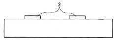
도 1은 본 발명의 실리콘 기판의 단면도이다.1 is a cross-sectional view of a silicon substrate of the present invention.
도 2는 본 발명의 잉크 토출 압력 발생 소자가 형성된 실리콘 기판의 단면도이다.2 is a cross-sectional view of a silicon substrate on which an ink discharge pressure generating element of the present invention is formed.
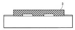
도 3은 본 발명의 수지층(밀착층)이 형성된 실리콘 기판의 단면도이다.3 is a cross-sectional view of a silicon substrate on which a resin layer (adhesive layer) of the present invention is formed.
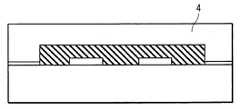
도 4는 본 발명의 액로 패턴이 형성된 실리콘 기판의 단면도이다.4 is a cross-sectional view of a silicon substrate on which a liquid channel pattern of the present invention is formed.
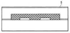
도 5는 본 발명의 액로 형성 부재가 되는 수지 재료가 형성된 실리콘 기판의 단면도이다.It is sectional drawing of the silicon substrate in which the resin material used as the fluid formation member of this invention was formed.
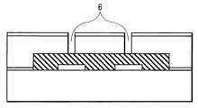
도 6은 본 발명의 잉크 반발층(ink repellent layer)이 형성된 실리콘 기판의 단면도이다.6 is a cross-sectional view of a silicon substrate on which an ink repellent layer of the present invention is formed.
도 7은 본 발명의 잉크 토출구가 형성된 실리콘 기판의 단면도이다.7 is a sectional view of a silicon substrate on which an ink discharge port of the present invention is formed.
도 8은 본 발명의 이면에 감광성 수지층이 형성된 실리콘 기판의 단면도이다.8 is a cross-sectional view of a silicon substrate on which a photosensitive resin layer is formed on the back surface of the present invention.
도 9는 감광성 수지층이 패턴화된 실리콘 기판의 단면도이다.9 is a cross-sectional view of a silicon substrate on which a photosensitive resin layer is patterned.
도 10은 본 발명의 잉크 공급구가 형성된 실리콘 기판의 단면도이다.10 is a sectional view of a silicon substrate on which an ink supply port of the present invention is formed.
도 11은 본 발명의 완성된 잉크젯 기록 헤드의 단면도이다.11 is a cross-sectional view of the completed inkjet recording head of the present invention.
<발명을 실시하기 위한 최선의 형태>Best Mode for Carrying Out the Invention
이하에 도면을 참조하여, 본 발명의 실시 형태를 더욱 상세히 설명한다.EMBODIMENT OF THE INVENTION Below, with reference to drawings, embodiment of this invention is described in detail.
도 1 내지 도 11은, 본 발명에 의한 잉크젯 기록 헤드의 구성 및 그의 제조 방법의 단면도를 모식적으로 나타낸 것이다.1 to 11 schematically show sectional views of the configuration of the inkjet recording head and the manufacturing method thereof according to the present invention.
본 발명에서는, 예를 들면 도 1에 표시되는 것과 같은 실리콘 기판 (9)를 준비한다. 이러한 기판은, 후술하는 잉크 유로 및 잉크 토출구를 형성하는 액로 형성 부재의 지지체로서 기능할 수 있는 것이면, 그 형상, 재질 등에 특별히 한정되지 않고 사용할 수 있지만, 본 실시 형태와 같이 이방성 에칭에 의해 기판을 관통하는 잉크 공급구를 형성하는 경우에는 실리콘 기판이 사용된다.In the present invention, for example, a
상기 실리콘 기판 (9) 상에는, 전기 열 변환 소자 또는 압전 소자 등의 잉크 토출 압력 발생 소자 (2)가 원하는 개수로 배치된다 (도 2). 이러한 잉크 토출 압력 발생 소자 (2)에 의해서, 기록 액적을 토출시키기 위한 토출 에너지가 잉크액에 공급되어 기록이 행해진다. 예를 들면, 상기 잉크 토출 압력 발생 소자 (2)로서 전기 열 변환 소자를 사용할 때에는, 이 소자가 근방의 기록액을 가열함으로써, 기록액에 상태 변화를 일으켜 토출 에너지를 발생한다. 또한, 예를 들어 압전 소자를 사용할 때에는, 이 소자의 기계적 진동에 의해서 토출 에너지가 발생된다.On the
이들 토출 압력 발생 소자 (2)에는 소자를 작동시키기 위한 제어 신호 입력용 전극(도시하지 않음)이 접속되어 있다. 일반적으로는 이들 토출 압력 발생 소자 (2)의 내구성 향상의 목적으로, 보호층 등(도시하지 않음)의 각종 기능층이 설치되며, 물론 본 발명에서도 이러한 기능층을 설치하는 것은 조금도 지장을 받지 않는다.These discharge pressure generating elements 2 are connected with electrodes for control signal input (not shown) for operating the elements. Generally, in order to improve the durability of these discharge pressure generating elements 2, various functional layers, such as a protective layer (not shown), are provided, and of course, in the present invention, such functional layers are not disturbed at all. .
토출 압력 발생 소자로서 통상 사용되는 전기 열 변환 소자는 발열 저항층 상에 전극층을 적층한 적층 구조를 소정의 배선 패턴으로 패턴화하고, 전극층의 소정부를 제거하여 하부에 있는 발열 저항층을 노출시킴으로써, 1쌍의 전극사이에 이들 전극에 접속한 발열 저항층의 노출부(전기 열 변환 소자)가 배치된 구성을 갖고 있다.The electrothermal conversion element commonly used as the discharge pressure generating element is formed by patterning a laminated structure in which an electrode layer is stacked on a heat generating resistive layer with a predetermined wiring pattern, and removing a predetermined portion of the electrode layer to expose the heat generating resistive layer below. And an exposed portion (electric heat conversion element) of the heat generating resistive layer connected to these electrodes is arranged between the pair of electrodes.
도 3에 나타낸 바와 같이, 두께 1 내지 3 ㎛의 수지층(밀착층) (10)을 스핀 코팅법, 롤 코팅법, 슬릿 코팅법 등의 코팅 방법에 의해 형성한다. 여기서 사용되는 수지층 (10)은 후술하는 액로 형성 부재 (4)와 지지 기판과의 밀착성을 향상시 키기 위해 사용하며, 실리콘 기판 (9) 상에 형성되는 SiN층이나 SiO2층 등의 무기 절연층(도시하지 않음) 및 액로 형성 부재의 유기 재료 모두에 대하여 우수한 밀착력을 가질 필요가 있다. 또한, 상기 수지층은 잉크에 접촉할 가능성이 있는 부재이기 때문에, 이들 구성 부재에 대하여 알칼리 조건하에서도 우수한 밀착성을 유지할 것이 특히 요구된다.As shown in Fig. 3, a resin layer (adhesive layer) 10 having a thickness of 1 to 3 mu m is formed by a coating method such as spin coating, roll coating or slit coating. The
또한 도 3에 나타낸 바와 같이, 수지층(밀착층) (10)은 잉크 토출 압력 발생 소자 (2) 및 후술하는 잉크 공급구 (7) 상에는 형성되지 않도록 패턴화할 필요가 있기 때문에, 감광성을 갖는 것을 사용한다. 본 발명자들은 예의 검토한 결과, 이들 특성을 만족하는 재료로서, 하기 화학식 1로 표시되는 반복 단위를 갖는 폴리에테르아미드 수지와, 광 조사에 의해 산을 발생하는 화합물(산 발생제)과, 산성 조건하에서 작용하는 상기 폴리에테르아미드 수지용 가교제를 포함하는 감광성 수지 조성물이 바람직하게 사용되는 것을 발견하였다.As shown in Fig. 3, since the resin layer (adhesive layer) 10 needs to be patterned so as not to be formed on the ink discharge pressure generating element 2 and the
폴리에테르아미드 수지, 산 발생제 및 가교제는 폴리에테르아미드 수지 100에 대하여 산 발생제 0.5 내지 10, 가교제 1 내지 40의 비율로 배합되는 것이 바람직하고, 산 발생제 1 내지 5, 가교제 10 내지 30의 비율로 배합되는 것이보다 바람직하다.It is preferable to mix | blend a polyetheramide resin, an acid generator, and a crosslinking agent with the ratio of the acid generator 0.5-10, and a crosslinking agent 1-40 with respect to the polyetheramide resin 100, and the acid generators 1-5 and a crosslinking agent 10-30 of It is more preferable to mix | blend in a ratio.
본 발명의 감광성 수지 조성물에 사용되는 폴리에테르아미드 수지로는, 예를 들면 하기 화학식 1로 표시되는 수지가 바람직하게 사용된다. 화학식 1로 표시되는 폴리에테르아미드 수지는, 예를 들면 일본 특허 공개 (소)63-6112호 공보에 기 재되어 있는 이미 알려져 있는 방법에 의해 합성할 수 있다.As a polyetheramide resin used for the photosensitive resin composition of this invention, resin represented by following General formula (1) is used preferably, for example. The polyetheramide resin represented by the formula (1) can be synthesized, for example, by a known method described in Japanese Patent Laid-Open No. 63-6112.
<화학식 1><Formula 1>

식 중, R1 내지 R4는 각각 독립적으로 수소 원자, 탄소수 1 내지 4의 알킬기, 탄소수 1 내지 4의 알콕시기 또는 할로겐 원자를 나타내고, R5 및 R6은 각각 독립적으로 수소 원자, 탄소수 1 내지 4의 알킬기 또는 탄소수 1 내지 4의 할로겐화 알킬기를 나타내며, Ar1은 치환 또는 비치환된 페닐렌, 비페닐렌 또는 나프틸렌을 나타내고, n은 양의 정수이다.In formula, R <1> -R <4> respectively independently represents a hydrogen atom, a C1-C4 alkyl group, a C1-C4 alkoxy group, or a halogen atom, R <5> and R <6> respectively independently represents a hydrogen atom, C1-C4 An alkyl group of 4 or a halogenated alkyl group of 1 to 4 carbon atoms, Ar1 represents a substituted or unsubstituted phenylene, biphenylene or naphthylene, and n is a positive integer.
본 발명에 사용되는 폴리에테르아미드 수지는, 예를 들면 테레프탈산, 이소프탈산, 옥시디벤조산, 비페닐디카르복실산 또는 나프탈렌디카르복실산의 디클로라이드와, 2,2-비스{4-(4-아미노페녹시)페닐}프로판 또는 2,2-비스{3-메틸-4-(4-아미노페녹시)페닐}프로판 등의 디아민을 중축합시켜 얻어진다. 상기 성분 이외의 성분으로서, 예를 들어 내열성 향상의 목적으로 4,4'-디아미노디페닐메탄, 3,3'-디아미노디페닐술폰 등의 디아민류를 첨가하여 중축합시켜 얻은 수지를 사용할 수도 있다.The polyetheramide resin used in the present invention is, for example, dichloride of terephthalic acid, isophthalic acid, oxydibenzoic acid, biphenyldicarboxylic acid or naphthalenedicarboxylic acid, and 2,2-bis {4- (4 It is obtained by polycondensation of diamines, such as -aminophenoxy) phenyl} propane or 2,2-bis {3-methyl-4- (4-aminophenoxy) phenyl} propane. As components other than the above components, for example, resins obtained by polycondensation by adding diamines such as 4,4'-diaminodiphenylmethane and 3,3'-diaminodiphenylsulfone for the purpose of improving heat resistance can be used. It may be.
폴리에테르아미드 수지는 중량 평균 분자량(
폴리에테르아미드 수지는 중량 평균 분자량(

또한, Ar1로는 p-페닐렌, m-페닐렌이 바람직하다.As Ar1 , p-phenylene and m-phenylene are preferable.
광 조사에 의해 산을 발생하는 화합물로는, 예를 들면 요오드늄염이나 술포늄염과 같은 오늄염, 할로겐화 트리아진 화합물, 디술폰 화합물, 술폰산에스테르 화합물 등을 바람직하게 사용할 수 있다.As a compound which generate | occur | produces an acid by light irradiation, onium salts, such as an iodonium salt and a sulfonium salt, a halogenated triazine compound, a disulfone compound, a sulfonic acid ester compound, etc. can be used preferably.
산성 조건하에서 작용하는 폴리에테르아미드 수지용 가교제의 예로는 산성 조건하에서 상술한 폴리에테르아미드 수지 중 이미노기와 축합 반응을 일으키는 멜라민 화합물이나, 우레아 화합물이 바람직하게 사용될 수 있고, 특히 헥사메틸올 멜라민, 테트라메틸올 멜라민, 헥사메톡시메틸 멜라민, 테트라메톡시메틸 멜라민, 헥사에톡시메틸 멜라민, 테트라에톡시메틸 멜라민 등의 메틸올화 멜라민, 그의 알킬에테르 화합물, 및 이들의 부분 축합 화합물이 바람직하게 사용된다. 또한, 광 반응성 및 저장 안정성이 우수하기 때문에, 헥사메톡시메틸 멜라민의 단량체를 90 중량% 이상 함유하는 가교제가 특히 바람직하게 사용된다.Examples of the crosslinking agent for polyetheramide resins that operate under acidic conditions include melamine compounds that cause condensation reactions with imino groups in the above-mentioned polyetheramide resins under acidic conditions, and urea compounds may be preferably used. Particularly, hexamethylol melamine, tetra Methylolated melamines such as methylol melamine, hexamethoxymethyl melamine, tetramethoxymethyl melamine, hexaethoxymethyl melamine, tetraethoxymethyl melamine, alkylether compounds thereof, and partially condensed compounds thereof are preferably used. Moreover, since the photoreactivity and storage stability are excellent, the crosslinking agent containing 90 weight% or more of the monomers of hexamethoxymethyl melamine is used especially preferably.
이들 성분을 포함하는 감광성 수지 조성물을 N-메틸-2-피롤리돈을 포함하는 용제에 5 내지 20 중량%의 농도로 희석하여, 스핀 코팅법, 롤 코팅법, 슬릿 코팅법 등의 코팅 방법에 의해 기판 상에 도포된다. 용제로는 N-메틸-2-피롤리돈 이외에도, 디에틸렌 글리콜 디메틸 에테르, 트리에틸렌 글리콜 디메틸 에테르 등을 사 용할 수 있다. 그 후, 통상의 포토리소그래피 공정에 의해 패턴화하고, 필요에 따라 가열 처리를 실시하여 조성물을 열경화시켜 도 3에 나타낸 바와 같이 수지층(밀착층) (10)을 형성한다. 상기 감광성 수지 조성물은 코팅 용제 이외에, 기재와의 밀착성 향상을 목적으로 실란 커플링제나, 광 감도 향상을 목적으로 증감제를 함유할 수도 있다.The photosensitive resin composition containing these components is diluted in the solvent containing N-methyl- 2-pyrrolidone at the density | concentration of 5 to 20 weight%, and it is applied to coating methods, such as a spin coating method, a roll coating method, and a slit coating method. Is applied onto the substrate. In addition to N-methyl-2-pyrrolidone, diethylene glycol dimethyl ether, triethylene glycol dimethyl ether, etc. can be used as a solvent. Thereafter, the substrate is patterned by a normal photolithography step, heat-treated as necessary, and the composition is thermally cured to form a resin layer (adhesive layer) 10 as shown in FIG. 3. In addition to a coating solvent, the said photosensitive resin composition may contain a silane coupling agent for the purpose of improving adhesiveness with a base material, and a sensitizer for the purpose of improving light sensitivity.
도 4에 나타낸 바와 같이, 상기 잉크 토출 압력 발생 소자 (2)를 갖는 실리콘 기판 (9) 상에 용해 가능한 수지로 잉크 유로 패턴 (3)을 형성한다. 가장 일반적인 방법으로는 감광성 재료로 형성하는 방법을 들 수 있다. 상기 유로 패턴 (3)은 후속 공정에서 용해 제거할 필요가 있기 때문에, 포지티브형 레지스트를 사용하는 것이 바람직하고, 특히 폴리메틸 이소프로페닐 케톤, 폴리비닐 케톤 등의 비닐 케톤계 광 붕괴형 고분자 화합물 또는 아크릴계 광 붕괴형 고분자 화합물을 바람직하게 사용할 수 있다.As shown in FIG. 4, the ink
예를 들면, 막 두께가 10 ㎛인 상기 광 붕괴형 고분자 화합물을 포함하는 막을 스핀 코팅법, 롤 코팅법, 슬릿 코팅법 등의 코팅 방법으로 형성한다. 그 후, 포토리소그래피법에 의해 원하는 유로 패턴 (3)을 형성한다. 도 5에 나타낸 바와 같이, 두께가 20 ㎛(평판상)인 액로 형성 부재 (4)를 형성하기 위한 재료를 유로 패턴 (3)이 형성된 실리콘 기판 (9) 상에 스핀 코팅법, 롤 코팅법, 슬릿 코팅법 등의 통상의 코팅 방법으로 형성한다. 액로 형성 부재 (4)를 형성하기 위해서는 유로 패턴 (3)을 변형시키지 않는 등의 특성이 필요해진다. 즉, 액로 형성 부재 (4)를 용제에 용해시키고, 얻어진 용액을 스핀 코팅, 롤 코팅 등으로 유로 패턴 (3) 상에 오버코팅하는 경우, 용해 가능한 유로 패턴 (3)이 용해되지 않도록 용제를 선택할 필요가 있다.For example, a film containing the light decaying polymer compound having a film thickness of 10 μm is formed by a coating method such as a spin coating method, a roll coating method, or a slit coating method. Thereafter, the desired
액로 형성 부재 (4)로는 잉크 토출구 (6)을 포토리소그래피로 쉽고 정밀하게 형성할 수 있기 때문에 감광성 부재가 바람직하다. 이러한 감광성 코팅 수지에는, 구조 재료로서의 높은 기계적 강도, 기재와의 밀착성, 내잉크성과 동시에 잉크 토출구의 미세한 패턴을 패턴화하기 위한 해상성이 요구된다. 이들 특성을 만족하는 재료로 양이온 중합형의 에폭시 수지 조성물을 바람직하게 사용할 수 있다.As the liquid
본 발명에 사용되는 에폭시 수지로는, 예를 들면 비스페놀 A와 에피클로로히드린과의 반응물 중 분자량이 약 900 이상인 것, 브로모페놀 A와 에피클로로히드린과의 반응물, 페놀 노볼락 또는 o-크레졸 노볼락과 에피클로로히드린과의 반응물, 일본 특허 공개 (소)60-161973호 공보, 일본 특허 공개 (소)63-221121호 공보, 일본 특허 공개 (소)64-9216호 공보, 일본 특허 공개 (평)2-140219호 공보에 기재된 옥시시클로헥산 골격을 갖는 다관능 에폭시 수지를 들 수 있지만, 이들 화합물에 한정되는 것은 아니다.Examples of the epoxy resin used in the present invention include those having a molecular weight of about 900 or more in a reaction product of bisphenol A with epichlorohydrin, a reaction product of bromophenol A with epichlorohydrin, a phenol novolac or o- Reaction of cresol novolac and epichlorohydrin, Japanese Patent Laid-Open No. 60-161973, Japanese Patent Laid-Open No. 63-221121, Japanese Patent Laid-Open No. 64-9216, Japanese Patent Although the polyfunctional epoxy resin which has the oxycyclohexane frame | skeleton of Unexamined-Japanese-Patent No. 2-140219 is mentioned, It is not limited to these compounds.
상술한 에폭시 화합물에서는 바람직하게는 에폭시 당량이 2000 이하, 더욱 바람직하게는 에폭시 당량이 1000 이하인 화합물이 바람직하게 사용된다. 이것은 에폭시 당량이 2000을 초과하면, 경화 반응시 가교 밀도가 저하하고, 밀착성, 내잉크성에 문제가 발생하는 경우가 있기 때문이다.In the above-mentioned epoxy compound, the compound whose epoxy equivalent is preferably 2000 or less, more preferably the epoxy equivalent is 1000 or less is used preferably. This is because when epoxy equivalent exceeds 2000, a crosslinking density may fall at the time of hardening reaction, and a problem may arise in adhesiveness and ink resistance.
상기 에폭시 수지를 경화시키기 위한 광 양이온 중합 개시제로는, 상술한 광 조사에 의해 산을 발생하는 화합물을 사용할 수 있고, 예를 들면 아사히 덴까사 (Asahi Denka Co.) 제조의 SP-150, SP-170, SP-172 등의 시판품을 바람직하게 사용할 수 있다.As a photocationic polymerization initiator for hardening the said epoxy resin, the compound which generate | occur | produces an acid by light irradiation mentioned above can be used, For example, SP-150, SP- by Asahi Denka Co., Ltd. make. Commercial items, such as 170 and SP-172, can be used preferably.
상술한 광 양이온 중합 개시제는 환원제를 병용하여 가열함으로써, 양이온 중합을 촉진시킬 수 있다 (단독의 광 양이온 중합에 비해 가교 밀도가 향상됨). 그러나, 광 양이온 중합 개시제와 환원제를 병용하는 경우, 상온에서는 반응하지 않고 일정 온도 이상(바람직하게는 60 ℃ 이상)에서 반응하는 소위 산화 환원형의 개시제계가 되도록 환원제를 선택할 필요가 있다. 이러한 환원제로는 구리 화합물, 특히 반응성과 에폭시 수지에의 용해성을 고려하여 구리 트리플레이트(트리플루오로메탄술폰산 구리(II))가 가장 적합하다. 필요에 따라, 상기 조성물에 첨가제 등을 적절히 첨가할 수 있다. 예를 들면, 에폭시 수지의 탄성률을 낮출 목적으로 가요성 부여제를 첨가하거나, 기재와의 밀착력을 보다 높이기 위해서 실란 커플링제를 첨가할 수 있다.The photocationic polymerization initiator mentioned above can promote cationic polymerization by using a reducing agent together and heating (crosslinking density improves compared with the photocationic polymerization of single). However, when using a photocationic polymerization initiator and a reducing agent together, it is necessary to select a reducing agent so that it may become a so-called redox type initiator system which does not react at normal temperature but reacts at a predetermined temperature or more (preferably 60 degreeC or more). As such a reducing agent, copper triflate (copper trifluoromethanesulfonic acid copper (II)) is most suitable in view of copper compounds, especially reactivity and solubility in epoxy resins. If necessary, an additive or the like can be appropriately added to the composition. For example, in order to reduce the elasticity modulus of an epoxy resin, a flexible imparting agent can be added, or a silane coupling agent can be added in order to improve adhesiveness with a base material more.
액로 형성 부재 (4) 상에 감광성을 갖는 잉크 반발층 (5)를 형성한다 (도 6). 잉크 반발층 (5)는 스핀 코팅법, 롤 코팅법, 슬릿 코팅법 등의 코팅 방법에 의해 형성 가능하지만, 미경화된 액로 형성 부재 (4) 상에 형성되기 때문에, 양자가 필요 이상으로 상용하지 않을 필요가 있다. 상술한 바와 같이 액로 형성 부재 (4)로서 양이온 중합성 조성물을 사용하는 경우에는, 감광성을 갖는 잉크 반발층 (5)에도 양이온 중합 가능한 관능기를 함유시켜 두는 것이 바람직하다. 액로 형성 부재 (4)는 광중합 개시제를 필수 성분으로서 포함하지만, 잉크 반발층 (5)에는 광중합 개시제를 반드시 포함시킬 필요는 없고, 액로 형성 부재 (4)의 노즐 재료 경 화시에 발생하는 양이온으로 반응, 경화시켜도 좋다.An
마스크(도시하지 않음)를 개재시켜 패턴 노광을 행하고, 현상 처리를 실시하여 잉크 토출구 (6)을 기판 상에 설치된 잉크 토출 압력 발생 소자 (2)와 대향하는 위치에 형성한다 (도 7). 패턴 노광된 액로 형성 부재 (4) 및 잉크 반발층 (5)를 적당한 용제를 사용하여 현상함으로써, 도 7에 나타낸 바와 같이 잉크 토출구 (6)을 형성할 수 있다. 이 때, 현상과 동시에 유로 패턴 (3)을 용해 제거하는 것도 가능하지만, 일반적으로 실리콘 기판 (9) 상에는 복수개의 헤드가 배치되고, 절단 공정을 거쳐 잉크젯 기록 헤드로서 사용되기 때문에, 절단시 먼지에 대한 대책으로서, 도 7에 나타낸 바와 같이 잉크 유로 패턴 (3)을 남기고(유로 패턴 (3)이 잔존하기 때문에, 절단시에 발생하는 먼지가 액로 내에 들어가는 것을 방지할 수 있음), 절단 공정 후에 유로 패턴 (3)을 용해 제거하는 것이 바람직하다.Pattern exposure is performed through a mask (not shown), and development processing is performed to form the
실리콘 기판 (9)를 관통하는 잉크 공급구를 형성한다. 잉크 공급구의 형성 방법으로는, 본 발명에 의한 감광성 수지 조성물을 마스크로서 사용하여 이방성 에칭을 행한다. 결정 방위로서, <100> 또는 <110>의 방위를 갖는 실리콘 기판은 알칼리계의 화학 에칭을 행함으로써, 에칭의 진행 방향에 관해 깊이 방향과 폭 방향의 선택성을 가질 수 있고, 이에 따라 에칭의 이방성을 얻을 수 있다. 특히, <100>의 결정 방위를 갖는 실리콘 기판은 에칭이 행해지는 폭에 의해서 에칭되는 기판의 깊이가 기하학적으로 결정되기 때문에, 에칭 깊이를 제어할 수 있고, 예를 들면 에칭의 개시면에서 깊이 방향으로 54.7°의 경사를 갖는 좁아지는 구멍을 형성할 수 있다.An ink supply port penetrating the
도 8에 나타낸 바와 같이, 우선 실리콘 기판 (9)의 이면에 본 발명에 의한 감광성 수지 조성물층 (11)을 형성하고, 마스크(도시하지 않음)를 사용하여 포트리소그래피에 의해 패턴화를 행한 후(도 9), 알칼리계 에칭액인 수산화칼륨, 수산화나트륨, 테트라메틸암모늄 히드록시드 등의 수용액에 침지시키고 에칭을 행하여 잉크 공급구 (7)을 형성한다 (도 10). 이 때, 일본 특허 공개 제2001-10070호 공보에 기재되어 있는 바와 같이, 핀홀 등의 결함을 방지할 목적으로 산화 실리콘, 질화 실리콘 등의 유전체막과의 2층 구성의 마스크로도 아무런 문제는 없다. 또한, 에칭 마스크는 밀착층 형성시 기판의 이면에 미리 형성시킬 수도 있다.As shown in FIG. 8, first, the photosensitive
절단 분리 공정을 거친 후(도시하지 않음), 유로 패턴 (3)을 용해 제거하고, 필요에 따라 에칭 마스크로서 사용한 감광성 수지 조성물층 (10)을 제거한다. 또한, 필요에 따라 가열 처리를 실시함으로써, 액로 형성 부재 (4) 및 잉크 반발층 (5)를 완전히 경화시킨 후, 잉크 공급을 위한 부재(도시하지 않음)와의 접합, 잉크 토출 압력 발생 소자를 구동하기 위한 전기적 접합(도시하지 않음)을 행하여 잉크젯 기록 헤드를 완성하였다 (도 11).After the cutting separation process (not shown), the
이하에, 실시예에 근거하여 본 발명을 더 자세히 설명한다.In the following, the present invention will be described in more detail based on examples.
(실시예 1)(Example 1)
·잉크젯 기록 헤드의 제조Preparation of inkjet recording head
본 실시예에서는, 상술한 도 1 내지 도 11에 나타낸 순서에 따라서 잉크젯 기록 헤드를 제조하여 평가를 행하였다.In this embodiment, an inkjet recording head was manufactured and evaluated in the order shown in Figs. 1 to 11 described above.
잉크 토출 압력 발생 소자 (2)로서의 전기 열 변환 소자(HfB2 재료로 이루어진 히터)와 잉크 액로 및 노즐 형성 부위에 SiN과 Ta의 적층막(도시하지 않음)을 갖는 실리콘 기판 (9)를 준비하였다 (도 1, 도 2). 하기에 나타내는 조성을 갖는 감광성 폴리에테르아미드 수지 조성물을 사용하여 수지층(밀착층) (10)을 형성하였다 (도 3).A

상기 화학식 3의 반복 단위를 갖는 중량 평균 분자량(
가교제 헥사메톡시메틸 멜라민 E-2151(상품명: 산와 케미컬사(Sanwa Chemical Co.)제) 2 중량부2 parts by weight of the crosslinking agent hexamethoxymethyl melamine E-2151 (trade name: manufactured by Sanwa Chemical Co.)
광중합 개시제 SP-172(상품명: 아사히 덴까사 제조) 0.5 중량부0.5 weight part of photoinitiators SP-172 (brand name: Asahi Denka Corporation make)
N-메틸-2-피롤리돈(NMP) 77.5 중량부N-methyl-2-pyrrolidone (NMP) 77.5 parts by weight
패턴화는 이하에 나타내는 공정 조건(이하, "패턴화 조건 (1)"로 지칭함)으로 행하였다. 자세하게는, 상기 감광성 폴리에테르아미드 수지 조성물을 실리콘 기판 (9)에 스핀 코팅으로 도포하여 두께 3.0 ㎛의 수지 조성물 막을 형성하였다. 이 막을 90 ℃에서 2 분간 핫 플레이트로 예비 소성하였다. 이 막을 캐논사(Canon Inc.) 제조의 마스크 얼라이너 MPA-600을 사용하여 1,000 mJ/㎝2로 노광시킨 후, 120 ℃에서 2 분간 핫 플레이트로 후노광 소성(PEB)을 실시하였다. 이 막을 NMP(N-메틸-2-피롤리돈)에서 60 초간, IPA(이소프로필 알코올)에서 30 초간 스핀 현상 처리를 실시하고, 30 초간 건조시키고, 250 ℃의 오븐에서 30 분간 경화하였다.Patterning was performed under the process conditions shown below (hereinafter, referred to as "patterning condition (1)"). In detail, the photosensitive polyetheramide resin composition was applied to the
피처리 기판 상에 폴리메틸 이소프로페닐 케톤(상표명: ODUR-1010, 도꾜 오까 고교사(Tokyo Ohka Kogyo Co.) 제조)을 사용하여 유로 패턴 (3)을 형성하였다 (도 4).A
패턴화는 이하에 나타내는 공정 조건(이하, "패턴화 조건 (2)"로 지칭함)에 의해 행하였다. 자세하게는, 막 두께 10 ㎛의 액로 패턴막을 스핀 코팅법으로 형성하고, 120 ℃에서 20 분간 핫 플레이트로 예비 소성하고, 캐논사 제조의 마스크 얼라이너 PLA-620을 사용하여 파장 254 nm의 빛에 1,500 mJ/㎝2으로 노광시켰다. 이 막을 메틸 이소부틸 케톤/크실렌=2/1 (중량비)의 혼합 용제에서 60 초간, 크실렌 용액에서 30 초간 스핀 현상 처리를 실시하고, 30 초간 건조시켰다.Patterning was performed under the process conditions (hereinafter, referred to as "patterning condition (2)"). Specifically, a liquid pattern film having a film thickness of 10 μm was formed by spin coating, prebaked at 120 ° C. for 20 minutes with a hot plate, and then subjected to 1,500 light at a wavelength of 254 nm using Canon's mask aligner PLA-620. It exposed at mJ / cm <2> . The film was spin-developed for 60 seconds in a mixed solvent of methyl isobutyl ketone / xylene = 2/1 (weight ratio) and 30 seconds in a xylene solution and dried for 30 seconds.
피처리 기판 상에 이하의 조성을 갖는 감광성 수지 조성물을 스핀 코팅으로 도포하고(평판상 막 두께 20 ㎛), 100 ℃에서 2 분간 핫 플레이트로 소성하여 액로 형성 부재 (4)를 형성하였다 (도 5).The photosensitive resin composition which has the following composition on a to-be-processed board | substrate was apply | coated by spin coating (flat-film thickness of 20 micrometers), and baked at 100 degreeC for 2 minutes by the hotplate, and the liquid-forming
에폭시 수지(다이셀 케미컬 인더스트리즈사(Daicel Chemical Industries) 제조 상품명: EHPE) 100 중량부100 parts by weight of an epoxy resin (trade name: EHPE, manufactured by Daicel Chemical Industries, Ltd.)
추가 수지(센트럴 글래스사(Central Glass Co.)제 상품명: 1.4HFAB) 20 중량부20 parts by weight of additional resin (trade name: 1.4HFAB manufactured by Central Glass Co.)
광 양이온 중합 촉매(아사히 덴까사 제조 상품명: SP-170) 2 중량부2 parts by weight of a photo cationic polymerization catalyst (Asahi Denka Co., Ltd. product name: SP-170)
실란 커플링제(닛뽄 유니까사(Nippon Unicar Co.) 제조 상품명: A-187) 5 중량부5 weight part of silane coupling agent (Nippon Unicar Co. make, brand name: A-187)
메틸 이소부틸 케톤 100 중량부100 parts by weight of methyl isobutyl ketone
디에틸렌 글리콜 디메틸 에테르(디글라임) 100 중량부100 parts by weight of diethylene glycol dimethyl ether (diglyme)
피처리 기판 상에 이하의 조성을 포함하는 감광성 수지 조성물을 스핀 코팅에 의해 1 ㎛의 막 두께가 되도록 도포하고, 80 ℃에서 3 분간 핫 플레이트로 소성하여 잉크 반발층 (5)를 형성하였다 (도 6).The photosensitive resin composition containing the following composition was apply | coated on the to-be-processed substrate so that it might become a film thickness of 1 micrometer by spin coating, and it baked at 80 degreeC for 3 minutes by the hotplate, and formed the ink repellent layer 5 (FIG. 6). ).
에폭시 수지(다이셀 케미컬 인더스트리즈사 제조(상품명: EHPE-3158)) 35 중량부35 weight part of epoxy resin (made by Daicel Chemical Industries, Ltd. (brand name: EHPE-3158))
2,2-비스(4-글리시딜옥시페닐)헥사플루오로프로판 25 중량부25 parts by weight of 2,2-bis (4-glycidyloxyphenyl) hexafluoropropane
1,4-비스(2-히드록시헥사플루오로이소프로필)벤젠 25 중량부25 parts by weight of 1,4-bis (2-hydroxyhexafluoroisopropyl) benzene
3-(2-퍼플루오로헥실)에톡시-1,2-에폭시프로판 16 중량부16 parts by weight of 3- (2-perfluorohexyl) ethoxy-1,2-epoxypropane
실란 커플링제(닛뽄 유니까사 제조 상품명: A-187) 4 중량부4 parts by weight of a silane coupling agent (trade name: A-187, manufactured by Nippon Yuoya Co., Ltd.)
광 양이온 중합 촉매(아사히 덴까사 제조 상품명: SP-170) 2 중량부2 parts by weight of a photo cationic polymerization catalyst (Asahi Denka Co., Ltd. product name: SP-170)
디에틸렌 글리콜 모노에틸에테르 100 중량부100 parts by weight of diethylene glycol monoethyl ether
이하에 나타내는 조건에 의해 액로 형성 부재 (4) 및 잉크 반발층 (5)의 패턴화를 행하여 잉크 토출구 (6)을 형성하였다 (도 7). 자세하게는, 캐논사 제조의 마스크 얼라이너 MPA-600으로 200 mJ/㎝2에서 기판을 노광하고, 노광 후 120 ℃에서 90 분간 핫 플레이트로 예비 소성하였다. 기판을 메틸 이소부틸 케톤에 60 초간, 이소프로필 알코올(IPA)에 30 초간 침지한 다음, 30 초간 건조하고, 130 ℃의 오븐에서 20 분간 경화시켜 스핀 현상 처리를 실시하였다. 본 실시예에서는 개구 직경이 15 ㎛인 토출구 패턴을 형성하였다.The liquid
피처리 기판의 이면에 패턴화 조건 (1)과 마찬가지의 조건으로 상술한 감광성 폴리에테르아미드 수지 조성물을 사용하여 폭 1 mm, 길이 10 mm의 개구부 형상을 패턴화하고, 200 ℃에서 60 분간의 열 처리를 행하여 에칭 마스크를 제조하였다. 80 ℃로 유지한 22 중량%의 TMAH 수용액 중에 피처리 기판을 침지하여 실리콘 기판 (9)의 이방성 에칭을 행하여, 잉크 공급구 (7)을 형성하였다 (도 8 내지 도 10). 이 때 에칭액으로부터 잉크 반발층 (5)를 보호할 목적으로, 보호막(도꾜 오까 고교사 제조 상품명: OBC)을 잉크 반발층 (5) 상에 도포하여 이방성 에칭을 행하였다.Using the photosensitive polyetheramide resin composition described above on the back surface of the substrate to be patterned, the opening shape having a width of 1 mm and a length of 10 mm was patterned, and then heated at 200 ° C. for 60 minutes. The treatment was performed to prepare an etching mask. The to-be-processed substrate was immersed in the 22 weight% TMAH aqueous solution maintained at 80 degreeC, and the anisotropic etching of the
보호막으로서 사용한 OBC를 크실렌을 사용하여 용해 제거한 후, 피처리 기판을 상술한 패턴화 조건 (2)에서 사용한 PLA-620로 3000 mJ/㎠의 전체면 노광을 행하여 유로 패턴 (3)을 가용화하였다. 메틸 이소부틸 케톤 중에 초음파를 인가하면서 기판을 침지하고, 유로 패턴 (3)을 용해 제거함으로써 잉크젯 기록 헤드를 제조하였다 (도 11). 에칭 마스크로서 사용한 감광성 폴리에테르아미드 수지 조성물층은 건식 에칭에 의해 제거하였다.After dissolving and removing OBC used as a protective film using xylene, the to-be-processed board | substrate was made to expose whole surface of 3000 mJ / cm <2> with PLA-620 used by the patterning conditions (2) mentioned above, and the
·밀착성의 평가Evaluation of adhesion
얻어진 잉크젯 기록 헤드를 이하에 나타내는 조성을 갖는 알칼리 잉크 중에 침지하여 압력솥 시험(PCT) (121 ℃ 포화 조건-100 시간)을 행하여 액로 형성 부재가 되는 수지 재료를 관찰하였더니, 변화는 관찰되지 않았다.The obtained inkjet recording head was immersed in an alkaline ink having a composition shown below, and subjected to a pressure cooker test (PCT) (121 ° C saturation conditions-100 hours) to observe a resin material serving as a liquid formation member, but no change was observed.
흑색 염료 3 중량부3 parts by weight of black dye
에틸렌 글리콜 5 중량부5 parts by weight of ethylene glycol
요소 3 중량부3 parts by weight of element
이소프로필 알코올2 중량부2 parts by weight of isopropyl alcohol
이온 교환수 87 중량부87 parts by weight of ion-exchanged water
(실시예 2)(Example 2)
광중합 개시제(아사히 덴까사 제조 상품명: SP-172)의 절반량의 증감제(아사히 덴까사 제조 상품명: SP-100)를 첨가한 감광성 폴리에테르아미드 수지 조성물을 사용하고, 패턴화할 때의 노광량을 500 mJ/㎠로 한 것 이외에는, 실시예 1과 동일하게 하여 잉크젯 기록 헤드를 제조하고, PCT 시험을 행하였다. 그 결과, 변화는 관찰되지 않았다.The exposure amount at the time of patterning using the photosensitive polyetheramide resin composition which added the sensitizer (Asahi Denka Corporation brand name: SP-100) of the half amount of a photoinitiator (Asahi Denka Corporation brand name: SP-172) is 500 Except having made mJ / cm <2>, the inkjet recording head was produced like Example 1, and the PCT test was done. As a result, no change was observed.
(실시예 3)(Example 3)
폴리에테르아미드 수지로서 하기의 반복 단위를 갖는 중량 평균 분자량(

(비교예 1)(Comparative Example 1)
수지층(밀착층) (10)을 형성하지 않는 것 이외에는, 실시예 1과 동일하게 하여 잉크젯 기록 헤드를 제조하고, PCT 시험을 행하였다. 그 결과, 액로 형성 부재 (4)와 실리콘 기판 (9) 사이에 박리가 확인되었다. 이것은 실리콘 기판 (9) 상에 형성된 SiN+Ta층과 액로 형성 부재 (4)와의 밀착성이 불충분하기 때문에 발생한 것으로 생각된다.Except not forming the resin layer (adhesive layer) 10, the inkjet recording head was manufactured like Example 1, and the PCT test was done. As a result, peeling was confirmed between the liquid-forming
(비교예 2)(Comparative Example 2)
수지층(밀착층) (10)으로서, 감광성 폴리이미드(도레이 인더스트리즈사 제조 상품명: 포토니스 UR3100)를 사용한 것 이외에는, 실시예 1과 동일하게 하여 잉크젯 기록 헤드를 제조하고, PCT 시험을 행하였다. 감광성 폴리이미드의 패턴화는 전용 현상액을 사용하여 제조자가 지정한 조건으로 행하고, 경화 조건은 130 ℃에서 30분+300 ℃에서 1 시간으로 하였다. 그 결과, 수지층(밀착층) (10)으로서 사용한 감광성 폴리이미드가 완전히 소실되어, 액로 형성 부재 (4)의 박리가 관찰되었다.As a resin layer (adhesive layer) 10, an inkjet recording head was produced in the same manner as in Example 1 except that photosensitive polyimide (trade name: Photonis UR3100 manufactured by Toray Industries, Inc.) was used, and a PCT test was performed. Patterning of the photosensitive polyimide was performed on the conditions which the manufacturer specified using the exclusive developing solution, and hardening conditions were made into 130 minutes at 130 degreeC +300 degreeC for 1 hour. As a result, the photosensitive polyimide used as the resin layer (adhesive layer) 10 completely disappeared, and peeling of the liquid
(비교예 3)(Comparative Example 3)
비감광성 폴리에테르아미드 수지(히다찌 케미컬사(Hitachi Chemical Co.) 제조 상품명: HIMAL-1200)를 사용하고, 포지티브형 레지스트(도꾜 오까 고교사제 상 품명: OFPR800)를 사용하여 산소 플라즈마에 의한 건식 에칭을 행한 후, 포지티브형 레지스트를 용해 제거하여 수지층(밀착층) (10)을 형성한 것 이외에는, 실시예 1과 동일하게 하여 잉크젯 기록 헤드를 제조하고, PCT 시험을 행하였다. 그 결과, 변화는 관찰되지 않았지만, 공정 단계가 증가하여 공정이 복잡해졌다.Dry etching by oxygen plasma was carried out using a non-photosensitive polyetheramide resin (trade name: HIMAL-1200 manufactured by Hitachi Chemical Co., Ltd.), and using a positive resist (trade name: OFPR800 manufactured by Toka Kogyo Co., Ltd.). Then, an inkjet recording head was produced in the same manner as in Example 1 except that the positive resist was dissolved and removed to form a resin layer (adhesive layer) 10, and a PCT test was performed. As a result, no change was observed, but the process step was increased and the process was complicated.
(비교예 4)(Comparative Example 4)
실리콘 기판 (9)의 이면용 에칭 마스크로서, 비감광성 폴리에테르아미드 수지(히다찌 케미컬사 제조 상품명: HIMAL-1200)를 사용하고, 포지티브형 레지스트(도꾜 오까 고교사제 상품명: OFPR800)를 사용하여 산소 플라즈마에 의한 건식 에칭을 행한 후, 포지티브형 레지스트를 용해 제거하여 수지 조성물층 (11)을 형성한 것 이외에는, 실시예 1과 동일하게 하여 잉크젯 기록 헤드를 제조하였다. 그 결과, 문제없이 잉크 공급구 (7)을 형성할 수 있었지만, 공정 단계가 증가하여 공정이 복잡해졌다.As an etching mask for the back surface of the
이상 설명한 바와 같이, 본 발명에 따르면 잉크젯 기록 헤드의 제조에 바람직한 감광성 수지 조성물을 제공할 수 있다. 또한, 본 발명에 의한 감광성 수지 조성물을 사용함으로써, 잉크 토출 압력 발생 소자가 형성된 기판과 액로 형성 부재와의 밀착력을 높이고, 그 결과 신뢰성이 높은 잉크젯 기록 헤드를 제공할 수 있다. 또한, 간편한 방법으로 신뢰성이 높은 잉크젯 기록 헤드를 제조하는 것이 가능해진다.As explained above, according to this invention, the photosensitive resin composition suitable for manufacture of an inkjet recording head can be provided. Further, by using the photosensitive resin composition according to the present invention, the adhesion between the substrate on which the ink discharge pressure generating element is formed and the liquid passage forming member can be increased, and as a result, a highly reliable inkjet recording head can be provided. In addition, it becomes possible to manufacture a highly reliable inkjet recording head in a simple manner.
Claims (12)
Translated fromKorean

Applications Claiming Priority (2)
| Application Number | Priority Date | Filing Date | Title |
|---|---|---|---|
| JPJP-P-2003-00170674 | 2003-06-16 | ||
| JP2003170674AJP3963456B2 (en) | 2003-06-16 | 2003-06-16 | Photosensitive resin composition, ink jet recording head using the same, and method for producing the same |
Publications (2)
| Publication Number | Publication Date |
|---|---|
| KR20060020680A KR20060020680A (en) | 2006-03-06 |
| KR100733939B1true KR100733939B1 (en) | 2007-06-29 |
Family
ID=33549433
Family Applications (1)
| Application Number | Title | Priority Date | Filing Date |
|---|---|---|---|
| KR1020057024097AExpired - Fee RelatedKR100733939B1 (en) | 2003-06-16 | 2004-06-10 | Photosensitive resin composition, ink-jet recording head using the composition, and production method for the same |
Country Status (8)
| Country | Link |
|---|---|
| US (1) | US7063933B2 (en) |
| EP (1) | EP1634123B1 (en) |
| JP (1) | JP3963456B2 (en) |
| KR (1) | KR100733939B1 (en) |
| CN (1) | CN100580556C (en) |
| AT (1) | ATE346326T1 (en) |
| DE (1) | DE602004003379T2 (en) |
| WO (1) | WO2004111732A1 (en) |
Families Citing this family (14)
| Publication number | Priority date | Publication date | Assignee | Title |
|---|---|---|---|---|
| JP5027991B2 (en)* | 2004-12-03 | 2012-09-19 | キヤノン株式会社 | Ink jet head and manufacturing method thereof |
| JP4656641B2 (en)* | 2005-06-02 | 2011-03-23 | キヤノン株式会社 | Recording head and recording apparatus |
| EP1752480A1 (en)* | 2005-08-12 | 2007-02-14 | Merck Patent GmbH | Polymerizable dielectric material |
| JP4854464B2 (en)* | 2005-10-20 | 2012-01-18 | キヤノン株式会社 | Liquid discharge head and manufacturing method thereof |
| JP4979641B2 (en)* | 2007-06-20 | 2012-07-18 | キヤノン株式会社 | Method for manufacturing liquid discharge head |
| KR20090062012A (en)* | 2007-12-12 | 2009-06-17 | 삼성전자주식회사 | Inkjet Head and Manufacturing Method Thereof |
| JP5388817B2 (en) | 2008-12-12 | 2014-01-15 | キヤノン株式会社 | Method for manufacturing liquid discharge head |
| WO2011010635A1 (en)* | 2009-07-21 | 2011-01-27 | 日産化学工業株式会社 | Composition forming heat cured film having photo alignment property |
| EP2557119B1 (en) | 2010-04-08 | 2015-12-09 | Nissan Chemical Industries, Ltd. | Composition forming heat-cured film having photo-alignment properties |
| JP6071565B2 (en) | 2013-01-11 | 2017-02-01 | キヤノン株式会社 | Method for manufacturing liquid discharge head |
| WO2016068947A1 (en) | 2014-10-30 | 2016-05-06 | Hewlett-Packard Development Company, L.P. | Ink jet printhead |
| JP6632225B2 (en)* | 2015-06-05 | 2020-01-22 | キヤノン株式会社 | Water repellent treatment method for the discharge port surface |
| JP7551296B2 (en)* | 2020-01-10 | 2024-09-17 | キヤノン株式会社 | LIQUID DISCHARGE HEAD AND METHOD FOR MANUFACTURING LIQUID DISCHARGE HEAD |
| US11666918B2 (en)* | 2020-03-06 | 2023-06-06 | Funai Electric Co., Ltd. | Microfluidic chip, head, and dispensing device for dispensing fluids containing an acidic component |
Citations (3)
| Publication number | Priority date | Publication date | Assignee | Title |
|---|---|---|---|---|
| US5474876A (en) | 1992-05-29 | 1995-12-12 | Basf Lacke + Farben Ag | Radiation-crosslinkable mixtures containing carboxyl-containing polymeric precursors |
| EP0962320A1 (en)* | 1998-06-03 | 1999-12-08 | Canon Kabushiki Kaisha | Ink-Jet head, ink-jet head substrate, and a method for making the head |
| EP0964440A2 (en)* | 1998-06-11 | 1999-12-15 | Canon Kabushiki Kaisha | Etching method for processing substrate, dry etching method for polyetheramide resin layer, production method of ink-jet printing head, ink-jet head and ink-jet printing apparatus |
Family Cites Families (20)
| Publication number | Priority date | Publication date | Assignee | Title |
|---|---|---|---|---|
| US4450455A (en) | 1981-06-18 | 1984-05-22 | Canon Kabushiki Kaisha | Ink jet head |
| JPS57208255A (en) | 1981-06-18 | 1982-12-21 | Canon Inc | Ink jet head |
| JPS57208256A (en) | 1981-06-18 | 1982-12-21 | Canon Inc | Ink jet head |
| US4595745A (en)* | 1983-06-27 | 1986-06-17 | Ube Industries, Ltd. | Organic solvent-soluble photosensitive polyamide resin |
| JPH0625194B2 (en) | 1984-01-30 | 1994-04-06 | ダイセル化学工業株式会社 | Novel epoxy resin manufacturing method |
| US4565859A (en) | 1984-01-30 | 1986-01-21 | Daicel Chemical Industries, Ltd. | Polyether compounds, epoxy resins, epoxy resin compositions, and processes for production thereof |
| JPS60180197A (en)* | 1984-02-27 | 1985-09-13 | 宇部興産株式会社 | Method for manufacturing multilayer printed wiring board |
| JPH0645242B2 (en) | 1984-12-28 | 1994-06-15 | キヤノン株式会社 | Liquid jet recording head manufacturing method |
| JPH07119269B2 (en) | 1986-08-26 | 1995-12-20 | ダイセル化学工業株式会社 | Epoxy resin |
| JPH0725864B2 (en) | 1987-03-09 | 1995-03-22 | ダイセル化学工業株式会社 | Epoxy resin |
| DE3889998T2 (en) | 1987-08-17 | 1994-11-03 | Daicel Chem | Polyether compounds, epoxy resins and processes for their preparation. |
| JPH0822902B2 (en) | 1988-11-21 | 1996-03-06 | ダイセル化学工業株式会社 | Method for producing epoxy resin |
| CA2019693A1 (en)* | 1989-07-07 | 1991-01-07 | Karen Ann Graziano | Acid-hardening photoresists of improved sensitivity |
| JP2697937B2 (en) | 1989-12-15 | 1998-01-19 | キヤノン株式会社 | Active energy ray-curable resin composition |
| JP3143307B2 (en) | 1993-02-03 | 2001-03-07 | キヤノン株式会社 | Method of manufacturing ink jet recording head |
| JP3957920B2 (en) | 1998-06-11 | 2007-08-15 | キヤノン株式会社 | Inkjet head manufacturing method |
| CN1235972C (en)* | 2000-12-01 | 2006-01-11 | 东丽株式会社 | Polyester composition, films made thereof and process for producing the composition |
| FR2824329B1 (en)* | 2001-05-03 | 2003-06-13 | Atofina | ANTISTATIC POLYMER COMPOSITIONS |
| US20040094761A1 (en)* | 2002-11-02 | 2004-05-20 | David Sparrowe | Polymerizable amine mixtures, amine polymer materials and their use |
| US6929891B2 (en)* | 2003-03-11 | 2005-08-16 | Arch Specialty Chemicals, Inc. | Photosensitive resin compositions |
- 2003
- 2003-06-16JPJP2003170674Apatent/JP3963456B2/ennot_activeExpired - Fee Related
- 2004
- 2004-06-10EPEP04746028Apatent/EP1634123B1/ennot_activeExpired - Lifetime
- 2004-06-10DEDE602004003379Tpatent/DE602004003379T2/ennot_activeExpired - Lifetime
- 2004-06-10WOPCT/JP2004/008500patent/WO2004111732A1/enactiveIP Right Grant
- 2004-06-10KRKR1020057024097Apatent/KR100733939B1/ennot_activeExpired - Fee Related
- 2004-06-10ATAT04746028Tpatent/ATE346326T1/ennot_activeIP Right Cessation
- 2004-06-10CNCN200480011699Apatent/CN100580556C/ennot_activeExpired - Fee Related
- 2004-12-10USUS11/008,221patent/US7063933B2/ennot_activeExpired - Fee Related
Patent Citations (3)
| Publication number | Priority date | Publication date | Assignee | Title |
|---|---|---|---|---|
| US5474876A (en) | 1992-05-29 | 1995-12-12 | Basf Lacke + Farben Ag | Radiation-crosslinkable mixtures containing carboxyl-containing polymeric precursors |
| EP0962320A1 (en)* | 1998-06-03 | 1999-12-08 | Canon Kabushiki Kaisha | Ink-Jet head, ink-jet head substrate, and a method for making the head |
| EP0964440A2 (en)* | 1998-06-11 | 1999-12-15 | Canon Kabushiki Kaisha | Etching method for processing substrate, dry etching method for polyetheramide resin layer, production method of ink-jet printing head, ink-jet head and ink-jet printing apparatus |
Also Published As
| Publication number | Publication date |
|---|---|
| DE602004003379D1 (en) | 2007-01-04 |
| DE602004003379T2 (en) | 2007-09-13 |
| WO2004111732A1 (en) | 2004-12-23 |
| ATE346326T1 (en) | 2006-12-15 |
| EP1634123A1 (en) | 2006-03-15 |
| KR20060020680A (en) | 2006-03-06 |
| US20050093924A1 (en) | 2005-05-05 |
| JP2005008652A (en) | 2005-01-13 |
| JP3963456B2 (en) | 2007-08-22 |
| CN1781058A (en) | 2006-05-31 |
| US7063933B2 (en) | 2006-06-20 |
| CN100580556C (en) | 2010-01-13 |
| EP1634123B1 (en) | 2006-11-22 |
Similar Documents
| Publication | Publication Date | Title |
|---|---|---|
| EP1380422B1 (en) | Method of manufacturing microstructure, method of manufacturing liquid discharge head, and liquid discharge head | |
| US6409316B1 (en) | Thermal ink jet printhead with crosslinked polymer layer | |
| US6139761A (en) | Manufacturing method of ink jet head | |
| KR100591654B1 (en) | Method of Producing Micro Structure, Method of Producing Liquid Discharge Head, and Liquid Discharge Head by the Same | |
| KR100823746B1 (en) | Resin composition, resin cured product and liquid discharge head | |
| KR100733939B1 (en) | Photosensitive resin composition, ink-jet recording head using the composition, and production method for the same | |
| US20030146955A1 (en) | Ink-jet recording head and its manufacturing method | |
| JP5224771B2 (en) | Manufacturing method of recording head substrate | |
| JP4480141B2 (en) | Method for manufacturing ink jet recording head | |
| US7175973B2 (en) | Ink jet recording head and method for manufacturing the same | |
| JP2009163189A (en) | Photosensitive polyetheramide composition, ink jet recording head using the same, and method for producing the same | |
| KR20100060423A (en) | Inkjet printhead and method of manufacturing the same | |
| KR20090030111A (en) | Manufacturing method of inkjet printer head and inkjet printer head manufactured by said method | |
| JP4708768B2 (en) | Method for manufacturing ink jet recording head | |
| JP2021115778A (en) | Liquid discharge head and manufacturing method of liquid discharge head | |
| JP2010208023A (en) | Method for manufacturing inkjet head and inkjet head | |
| JP2005161595A (en) | Ink jet recording head and manufacturing method thereof | |
| JP2014094529A (en) | Ink jet recording head and method for manufacturing the same | |
| JP2007038525A (en) | Ink jet head and manufacturing method thereof | |
| AU734775B2 (en) | Manufacturing method of ink jet head | |
| JP2004330486A (en) | Method of manufacturing inkjet head | |
| JP2006069009A (en) | Inkjet head manufacturing method | |
| JP2001105601A (en) | Composition for forming liquid flow path of liquid jet recording head and method of manufacturing liquid jet recording head | |
| JP2005161594A (en) | Ink jet head and method of manufacturing ink jet head | |
| MXPA96002526A (en) | Method of manufacturing head of it jet |
Legal Events
| Date | Code | Title | Description |
|---|---|---|---|
| A201 | Request for examination | ||
| PA0105 | International application | St.27 status event code:A-0-1-A10-A15-nap-PA0105 | |
| PA0201 | Request for examination | St.27 status event code:A-1-2-D10-D11-exm-PA0201 | |
| P11-X000 | Amendment of application requested | St.27 status event code:A-2-2-P10-P11-nap-X000 | |
| P13-X000 | Application amended | St.27 status event code:A-2-2-P10-P13-nap-X000 | |
| PG1501 | Laying open of application | St.27 status event code:A-1-1-Q10-Q12-nap-PG1501 | |
| E902 | Notification of reason for refusal | ||
| PE0902 | Notice of grounds for rejection | St.27 status event code:A-1-2-D10-D21-exm-PE0902 | |
| P11-X000 | Amendment of application requested | St.27 status event code:A-2-2-P10-P11-nap-X000 | |
| P13-X000 | Application amended | St.27 status event code:A-2-2-P10-P13-nap-X000 | |
| E701 | Decision to grant or registration of patent right | ||
| PE0701 | Decision of registration | St.27 status event code:A-1-2-D10-D22-exm-PE0701 | |
| GRNT | Written decision to grant | ||
| PR0701 | Registration of establishment | St.27 status event code:A-2-4-F10-F11-exm-PR0701 | |
| PR1002 | Payment of registration fee | St.27 status event code:A-2-2-U10-U12-oth-PR1002 Fee payment year number:1 | |
| PG1601 | Publication of registration | St.27 status event code:A-4-4-Q10-Q13-nap-PG1601 | |
| R18-X000 | Changes to party contact information recorded | St.27 status event code:A-5-5-R10-R18-oth-X000 | |
| R17-X000 | Change to representative recorded | St.27 status event code:A-5-5-R10-R17-oth-X000 | |
| PR1001 | Payment of annual fee | St.27 status event code:A-4-4-U10-U11-oth-PR1001 Fee payment year number:4 | |
| PR1001 | Payment of annual fee | St.27 status event code:A-4-4-U10-U11-oth-PR1001 Fee payment year number:5 | |
| FPAY | Annual fee payment | Payment date:20120524 Year of fee payment:6 | |
| PR1001 | Payment of annual fee | St.27 status event code:A-4-4-U10-U11-oth-PR1001 Fee payment year number:6 | |
| FPAY | Annual fee payment | Payment date:20130528 Year of fee payment:7 | |
| PR1001 | Payment of annual fee | St.27 status event code:A-4-4-U10-U11-oth-PR1001 Fee payment year number:7 | |
| LAPS | Lapse due to unpaid annual fee | ||
| PC1903 | Unpaid annual fee | St.27 status event code:A-4-4-U10-U13-oth-PC1903 Not in force date:20140626 Payment event data comment text:Termination Category : DEFAULT_OF_REGISTRATION_FEE | |
| PC1903 | Unpaid annual fee | St.27 status event code:N-4-6-H10-H13-oth-PC1903 Ip right cessation event data comment text:Termination Category : DEFAULT_OF_REGISTRATION_FEE Not in force date:20140626 |