KR100730845B1 - Ultrasonic irradiation device - Google Patents
Ultrasonic irradiation deviceDownload PDFInfo
- Publication number
- KR100730845B1 KR100730845B1KR1020027015637AKR20027015637AKR100730845B1KR 100730845 B1KR100730845 B1KR 100730845B1KR 1020027015637 AKR1020027015637 AKR 1020027015637AKR 20027015637 AKR20027015637 AKR 20027015637AKR 100730845 B1KR100730845 B1KR 100730845B1
- Authority
- KR
- South Korea
- Prior art keywords
- ultrasonic
- irradiator
- vibrators
- sheet
- flexible
- Prior art date
- Legal status (The legal status is an assumption and is not a legal conclusion. Google has not performed a legal analysis and makes no representation as to the accuracy of the status listed.)
- Expired - Fee Related
Links
Images


Classifications
- B—PERFORMING OPERATIONS; TRANSPORTING
- B06—GENERATING OR TRANSMITTING MECHANICAL VIBRATIONS IN GENERAL
- B06B—METHODS OR APPARATUS FOR GENERATING OR TRANSMITTING MECHANICAL VIBRATIONS OF INFRASONIC, SONIC, OR ULTRASONIC FREQUENCY, e.g. FOR PERFORMING MECHANICAL WORK IN GENERAL
- B06B1/00—Methods or apparatus for generating mechanical vibrations of infrasonic, sonic, or ultrasonic frequency
- B06B1/02—Methods or apparatus for generating mechanical vibrations of infrasonic, sonic, or ultrasonic frequency making use of electrical energy
- B06B1/06—Methods or apparatus for generating mechanical vibrations of infrasonic, sonic, or ultrasonic frequency making use of electrical energy operating with piezoelectric effect or with electrostriction
- B06B1/0607—Methods or apparatus for generating mechanical vibrations of infrasonic, sonic, or ultrasonic frequency making use of electrical energy operating with piezoelectric effect or with electrostriction using multiple elements
- B06B1/0622—Methods or apparatus for generating mechanical vibrations of infrasonic, sonic, or ultrasonic frequency making use of electrical energy operating with piezoelectric effect or with electrostriction using multiple elements on one surface
- B06B1/0637—Spherical array
- A—HUMAN NECESSITIES
- A61—MEDICAL OR VETERINARY SCIENCE; HYGIENE
- A61F—FILTERS IMPLANTABLE INTO BLOOD VESSELS; PROSTHESES; DEVICES PROVIDING PATENCY TO, OR PREVENTING COLLAPSING OF, TUBULAR STRUCTURES OF THE BODY, e.g. STENTS; ORTHOPAEDIC, NURSING OR CONTRACEPTIVE DEVICES; FOMENTATION; TREATMENT OR PROTECTION OF EYES OR EARS; BANDAGES, DRESSINGS OR ABSORBENT PADS; FIRST-AID KITS
- A61F7/00—Heating or cooling appliances for medical or therapeutic treatment of the human body
- A—HUMAN NECESSITIES
- A61—MEDICAL OR VETERINARY SCIENCE; HYGIENE
- A61H—PHYSICAL THERAPY APPARATUS, e.g. DEVICES FOR LOCATING OR STIMULATING REFLEX POINTS IN THE BODY; ARTIFICIAL RESPIRATION; MASSAGE; BATHING DEVICES FOR SPECIAL THERAPEUTIC OR HYGIENIC PURPOSES OR SPECIFIC PARTS OF THE BODY
- A61H23/00—Percussion or vibration massage, e.g. using supersonic vibration; Suction-vibration massage; Massage with moving diaphragms
- A61H23/02—Percussion or vibration massage, e.g. using supersonic vibration; Suction-vibration massage; Massage with moving diaphragms with electric or magnetic drive
- A—HUMAN NECESSITIES
- A61—MEDICAL OR VETERINARY SCIENCE; HYGIENE
- A61N—ELECTROTHERAPY; MAGNETOTHERAPY; RADIATION THERAPY; ULTRASOUND THERAPY
- A61N7/00—Ultrasound therapy
- B—PERFORMING OPERATIONS; TRANSPORTING
- B06—GENERATING OR TRANSMITTING MECHANICAL VIBRATIONS IN GENERAL
- B06B—METHODS OR APPARATUS FOR GENERATING OR TRANSMITTING MECHANICAL VIBRATIONS OF INFRASONIC, SONIC, OR ULTRASONIC FREQUENCY, e.g. FOR PERFORMING MECHANICAL WORK IN GENERAL
- B06B1/00—Methods or apparatus for generating mechanical vibrations of infrasonic, sonic, or ultrasonic frequency
- B06B1/02—Methods or apparatus for generating mechanical vibrations of infrasonic, sonic, or ultrasonic frequency making use of electrical energy
- B06B1/06—Methods or apparatus for generating mechanical vibrations of infrasonic, sonic, or ultrasonic frequency making use of electrical energy operating with piezoelectric effect or with electrostriction
- B06B1/0688—Methods or apparatus for generating mechanical vibrations of infrasonic, sonic, or ultrasonic frequency making use of electrical energy operating with piezoelectric effect or with electrostriction with foil-type piezoelectric elements, e.g. PVDF
- G—PHYSICS
- G10—MUSICAL INSTRUMENTS; ACOUSTICS
- G10K—SOUND-PRODUCING DEVICES; METHODS OR DEVICES FOR PROTECTING AGAINST, OR FOR DAMPING, NOISE OR OTHER ACOUSTIC WAVES IN GENERAL; ACOUSTICS NOT OTHERWISE PROVIDED FOR
- G10K11/00—Methods or devices for transmitting, conducting or directing sound in general; Methods or devices for protecting against, or for damping, noise or other acoustic waves in general
- G10K11/004—Mounting transducers, e.g. provided with mechanical moving or orienting device
- H—ELECTRICITY
- H04—ELECTRIC COMMUNICATION TECHNIQUE
- H04R—LOUDSPEAKERS, MICROPHONES, GRAMOPHONE PICK-UPS OR LIKE ACOUSTIC ELECTROMECHANICAL TRANSDUCERS; DEAF-AID SETS; PUBLIC ADDRESS SYSTEMS
- H04R17/00—Piezoelectric transducers; Electrostrictive transducers
- A—HUMAN NECESSITIES
- A61—MEDICAL OR VETERINARY SCIENCE; HYGIENE
- A61B—DIAGNOSIS; SURGERY; IDENTIFICATION
- A61B17/00—Surgical instruments, devices or methods
- A61B17/22—Implements for squeezing-off ulcers or the like on inner organs of the body; Implements for scraping-out cavities of body organs, e.g. bones; for invasive removal or destruction of calculus using mechanical vibrations; for removing obstructions in blood vessels, not otherwise provided for
- A61B17/225—Implements for squeezing-off ulcers or the like on inner organs of the body; Implements for scraping-out cavities of body organs, e.g. bones; for invasive removal or destruction of calculus using mechanical vibrations; for removing obstructions in blood vessels, not otherwise provided for for extracorporeal shock wave lithotripsy [ESWL], e.g. by using ultrasonic waves
- A61B17/2251—Implements for squeezing-off ulcers or the like on inner organs of the body; Implements for scraping-out cavities of body organs, e.g. bones; for invasive removal or destruction of calculus using mechanical vibrations; for removing obstructions in blood vessels, not otherwise provided for for extracorporeal shock wave lithotripsy [ESWL], e.g. by using ultrasonic waves characterised by coupling elements between the apparatus, e.g. shock wave apparatus or locating means, and the patient, e.g. details of bags, pressure control of bag on patient
- A61B2017/2253—Implements for squeezing-off ulcers or the like on inner organs of the body; Implements for scraping-out cavities of body organs, e.g. bones; for invasive removal or destruction of calculus using mechanical vibrations; for removing obstructions in blood vessels, not otherwise provided for for extracorporeal shock wave lithotripsy [ESWL], e.g. by using ultrasonic waves characterised by coupling elements between the apparatus, e.g. shock wave apparatus or locating means, and the patient, e.g. details of bags, pressure control of bag on patient using a coupling gel or liquid
- A—HUMAN NECESSITIES
- A61—MEDICAL OR VETERINARY SCIENCE; HYGIENE
- A61B—DIAGNOSIS; SURGERY; IDENTIFICATION
- A61B18/00—Surgical instruments, devices or methods for transferring non-mechanical forms of energy to or from the body
- A61B2018/00005—Cooling or heating of the probe or tissue immediately surrounding the probe
- A61B2018/00041—Heating, e.g. defrosting
- A—HUMAN NECESSITIES
- A61—MEDICAL OR VETERINARY SCIENCE; HYGIENE
- A61N—ELECTROTHERAPY; MAGNETOTHERAPY; RADIATION THERAPY; ULTRASOUND THERAPY
- A61N7/00—Ultrasound therapy
- A61N2007/0078—Ultrasound therapy with multiple treatment transducers
Landscapes
- Engineering & Computer Science (AREA)
- Health & Medical Sciences (AREA)
- Mechanical Engineering (AREA)
- General Health & Medical Sciences (AREA)
- Veterinary Medicine (AREA)
- Public Health (AREA)
- Life Sciences & Earth Sciences (AREA)
- Animal Behavior & Ethology (AREA)
- Acoustics & Sound (AREA)
- Physics & Mathematics (AREA)
- Biomedical Technology (AREA)
- Radiology & Medical Imaging (AREA)
- Nuclear Medicine, Radiotherapy & Molecular Imaging (AREA)
- Multimedia (AREA)
- Pain & Pain Management (AREA)
- Vascular Medicine (AREA)
- Epidemiology (AREA)
- Heart & Thoracic Surgery (AREA)
- Physical Education & Sports Medicine (AREA)
- Rehabilitation Therapy (AREA)
- Signal Processing (AREA)
- Surgical Instruments (AREA)
- Thermotherapy And Cooling Therapy Devices (AREA)
- Percussion Or Vibration Massage (AREA)
- Physical Or Chemical Processes And Apparatus (AREA)
Abstract
Translated fromKoreanDescription
Translated fromKorean본 발명은 생체 등의 피조사체의 넓은 면적에 초음파를 조사하는 장치에 관한 것이다.
The present invention relates to an apparatus for irradiating ultrasonic waves to a large area of a subject such as a living body.
본 발명자는, 먼저, 특정 주파수의 초음파를 생체에 조사하는 것에 의해 생체내의 지방을 분해할 수 있다는 것을 발견하였다. 본 발명자는, 지방 분해를 위한 초음파 조사 장치에 대해 특허출원하고 있다(국제 공개 공보 WO99/39677 참조).The present inventors first discovered that fat in vivo can be decomposed by irradiating a living body with ultrasonic waves of a specific frequency. The present inventor has filed a patent for an ultrasonic irradiation apparatus for lipolysis (see International Publication WO99 / 39677).
상기 용도에서는, 생체에 초음파를 조사하는 것이 필요하지만, 생체는 복부(腹部), 대퇴부(大腿部), 둔부(臀部), 턱부(顎部) 등과 같이 복잡한 요철로 이루어지는 넓은 3차원적 곡면을 가지므로, 그 표면에 초음파를 균일하게 조사하는 것이 어렵다. In this application, it is necessary to irradiate the living body with ultrasonic waves, but the living body has a wide three-dimensional curved surface made of complex irregularities such as the abdomen, thigh, buttocks, and jaw. Therefore, it is difficult to irradiate the surface uniformly with ultrasonic waves.
그래서, 상기 국제 공개 공보에는,So, in the international publication,
(1) 욕조의 측벽에 초음파 진동자를 장착하고, 욕조내의 생체에, 욕조내의 물을 매개로 초음파를 조사하는 장치,(1) an apparatus for attaching an ultrasonic vibrator to a side wall of a bathtub, and irradiating ultrasonic waves to living bodies in the bathtub through water in the bathtub;
(2) 상측이 개방된 수조의 저부에 초음파 진동자를 장착하고, 상측의 개방부 에서 수조내의 물에 접촉하는 생체에, 수조내의 물을 매개로 초음파를 조사하는 장치,(2) an apparatus for attaching an ultrasonic vibrator to the bottom of an open tank of the upper side and irradiating ultrasonic waves to the living body in contact with the water in the tank from the upper open portion by means of water in the tank;
(3) 샤워 헤드 내에 초음파 진동자를 장착하고, 샤워 헤드로 유통되는 물 또는 온수를 매개로 생체에 초음파를 조사하는 장치 등이 개시되어 있다.(3) An apparatus for mounting an ultrasonic vibrator in a shower head and irradiating ultrasonic waves to living bodies through water or hot water circulated to the shower head is disclosed.
또한, 종래에, 미용, 혈액 순환 촉진, 어깨 결림, 요통 치료등을 위하여 생체에 초음파를 조사하는 것이 행해지고 있으며, 그를 위한 초음파 조사 장치가 알려져 있다. 이들 초음파 조사장치는, 직경이 약20 ~ 50mm의 단일 초음파 진동자를 구비하고, 음향 출력부를 신체 표면을 따라 주사(走査)하는 것에 의해, 필요한 범위로 초음파를 조사하는 것이다. 상기 종래의 초음파 조사 장치는, 생체를 따라 주사하기 때문에, 욕조, 수조, 샤워 등의 대형 장치를 필요로 하지 않고, 3차원 곡면을 가지는 생체에 초음파를 용이하게 조사할 수 있다. 그러나, 상기 장치는, 단일 초음파 진동자를 수동으로 주사하기 때문에, 주사하는 면적이 넓어지면, 단위면적당 필요한 조사량(조사강도 ×조사 누적 시간)을 얻기 위하여 장시간을 필요로 하고, 의사 등, 조작자의 부담이 커지게 된다.In addition, conventionally, ultrasonic waves are irradiated to a living body for beauty treatment, blood circulation promotion, shoulder stiffness, low back pain treatment, and the like, and an ultrasonic irradiation apparatus therefor is known. These ultrasonic irradiation devices are provided with a single ultrasonic vibrator having a diameter of about 20 to 50 mm, and irradiate ultrasonic waves in a necessary range by scanning the sound output unit along the body surface. Since the conventional ultrasonic irradiation apparatus scans along a living body, ultrasonic waves can be easily irradiated to a living body having a three-dimensional curved surface without the need for a large-sized device such as a bathtub, a water tank, or a shower. However, since the apparatus manually scans a single ultrasonic vibrator, when the area to be scanned is widened, a long time is required to obtain a required dose (irradiation intensity x irradiation cumulative time) per unit area, and a burden on an operator, such as a doctor, is required. Will become large.
상기 국제 공개 공보에는, 단일 초음파 진동자의 앞면에 음향 렌즈를 구비하고, 물, 젤리 등의 초음파 전달 매체를 수용하는 자루형 바디를 개재해서 생체에 초음파를 조사하는 장치도 개시되어 있다. 이러한 장치에 의하면, 상기 자루형 바디를 매개로 하여 생체에 밀착시킬 수 있음과 동시에, 상기 음향 렌즈의 작용에 의해 단일 초음파 진동자에서 조사 가능한 범위가 넓어지므로, 효율적으로 주사하는 것이 가능하다.The international publication also discloses an apparatus for irradiating ultrasonic waves to a living body through an acoustic lens provided on the front face of a single ultrasonic vibrator and through a bag-shaped body accommodating an ultrasonic transmission medium such as water and jelly. According to such an apparatus, it is possible to be in close contact with a living body through the bag-shaped body, and the range that can be irradiated by a single ultrasonic vibrator is widened by the action of the acoustic lens, so that scanning can be performed efficiently.
그러나, 주사하는 면적이 커지게 되었을 때, 단위면적당 필요한 조사량을 얻기 위하여 오랜 시간을 요하고, 조작자의 부담이 커지는 점에서는, 상기한 종래의 초음파 조사 장치와 마찬가지이다.However, when the area to be scanned becomes large, it takes a long time to obtain the required dose per unit area, and the burden on the operator becomes large, similar to the conventional ultrasonic irradiation apparatus described above.
또한, 상기 초음파 전달 매체를 수용하는 자루형 바디를 개재하여 초음파를 조사하는 장치에서는, 조사 범위를 넓게 하기 위하여는 음향 렌즈와, 상기 자루형 바디의 생체에 접하는 초음파 출력창 부분과의 거리가 멀어지고, 수량(水量)이 증가한다. 이 때문에, 물의 중량이 생체에 작용함과 동시에, 물의 중량을 지탱하는 조정이 어렵다.In addition, in the apparatus for irradiating ultrasonic waves through a bag-shaped body accommodating the ultrasonic transmission medium, in order to increase the irradiation range, the distance between the acoustic lens and the portion of the ultrasonic output window in contact with the living body of the bag-shaped body is far. And the quantity increases. For this reason, while the weight of water acts on a living body, it is difficult to adjust to support the weight of water.
더욱이, 상기 초음파 전달 매체를 수용하는 자루형 바디를 개재하여 초음파를 조사하는 장치에서는, 조사 방향이 거의 수직하지 않으면, 상기 자루형 바디의 초음파 출력창이 중력에 의해 크게 변형되어 원활한 주사가 어렵게 되기 때문에, 조사 자세가 제한된다.
Furthermore, in the apparatus for irradiating ultrasonic waves through a bag-shaped body accommodating the ultrasonic delivery medium, if the irradiation direction is almost not vertical, the ultrasonic output window of the bag-shaped body is greatly deformed by gravity, which makes it difficult to smoothly scan. Investigation posture is limited.
본 발명은, 이러한 사정을 감안하여, 3차원 곡면을 가지는 피조사체의 넓은 범위에 초음파를 용이하게 조사할 수 있는 장치를 제공하는 것을 목적으로 한다.In view of such circumstances, it is an object of the present invention to provide an apparatus capable of easily irradiating ultrasonic waves to a wide range of an object having a three-dimensional curved surface.
상기 목적을 달성하기 위하여, 본 발명의 초음파 조사 장치는, 복수의 초음파 진동자를 평면상태로 배열하고, 적어도 일부의 초음파 진동자의 위치를 서로 3차원적으로 변경이 자유롭게 설치한 초음파 조사(照射子)를 구비하는 것을 특징으로 한다. 또, 본 명세서에서는 상기 「3차원적으로 변경이 자유롭다」라는 것은, 2 차원적으로도 변경이 자유롭다는 의미를 포함하는 것으로 한다.In order to achieve the above object, the ultrasonic irradiation apparatus of the present invention, the ultrasonic irradiation is arranged in a planar state, a plurality of ultrasonic vibrators freely change the position of at least some of the ultrasonic vibrators three-dimensionally each other (照射 子) Characterized in having a. In addition, in this specification, said "change free in three dimensions" shall include the meaning that change is free in two dimensions.
본 발명의 초음파 조사장치에 의하면, 복수의 초음파 진동자가 평면상태로 배열되어 있기 때문에, 단일 초음파 진동자를 구비하는 초음파 조사 장치에 비하여, 피조사체에 일회에 초음파를 조사할 수 있는 범위가 현저히 넓어진다. 따라서, 피조사체의 넓은 범위에 초음파를 조사할 때, 조작자의 부담을 경감시킬 수 있다.According to the ultrasonic irradiation device of the present invention, since the plurality of ultrasonic vibrators are arranged in a planar state, the range in which ultrasonic waves can be irradiated to the irradiated object at once is significantly wider than that of the ultrasonic irradiation device having a single ultrasonic vibrator. . Therefore, when irradiating an ultrasonic wave to a wide range of a to-be-tested object, the burden of an operator can be reduced.
또한, 본 발명의 초음파 조사 장치에 의하면, 평면상태로 배열된 복수의 초음파 진동자 중, 적어도 일부의 초음파 진동자의 위치가, 서로 3차원적으로 변경이 자유롭게 되어 있다. 따라서, 상기 초음파 진동자를 생체와 같은 3차원적 곡면을 가지는 피조사체의 표면을 따라 배치하는 것이 가능하며, 상기 피조사체에 초음파를 균일하게 조사하는 것이 가능하다.Moreover, according to the ultrasonic irradiation apparatus of this invention, the position of at least one ultrasonic vibrator among the several ultrasonic vibrators arrange | positioned in planar state is free to change three-dimensionally mutually. Therefore, it is possible to arrange the ultrasonic vibrator along the surface of the irradiated object having a three-dimensional curved surface such as a living body, and to irradiate the irradiated object with ultrasonic waves uniformly.
본 발명의 초음파 조사 장치에 있어서, 상기 복수의 초음파 진동자의 위치를 서로 3차원적으로 변경이 자유롭게 하기 위하여, 상기 초음파 조사자는, 복수의 초음파 진동자가 가요성 및/또는 신축성 시트체(Sheet-like material)의 표면에 장착되는 것을 특징으로 한다. 상기 가요성 및/또는 신축성 시트체로서, 예를 들어, 각종 고무제의 시트체, 발포 부틸렌, 발포 실리콘과 같은 스폰지상 고무(Foam rubber)제의 시트체, 직포, 섬유상 부직포 등을 사용할 수 있다.In the ultrasonic irradiation apparatus of the present invention, in order to freely change the positions of the plurality of ultrasonic vibrators three-dimensionally, the ultrasonic irradiator includes a plurality of ultrasonic vibrators that are flexible and / or stretchable sheets. It is characterized in that the mounting on the surface of the material). As the flexible and / or stretchable sheet body, for example, a sheet body made of various rubbers, a foamed butylene, a sheet made of a sponge rubber such as foamed silicone, a woven fabric, a fibrous nonwoven fabric, or the like can be used. have.
상기 시트체는, 상기 초음파 진동자의 위치를 서로 3차원적으로 변경 자유롭게 하기 위하여, 신축성을 구비하는 것이 바람직하지만, 가요성을 구비하는 것이어도 좋다. 상기 시트체가 가요성만을 구비하는 경우, 해당 시트체는 일방향으로는 양호한 가요성을 나타내지만, 일방향으로 변형시켰을 때에, 상기 방향에 교차하는 방향으로는 변형하기 어렵다.The sheet body preferably has elasticity in order to freely change the position of the ultrasonic vibrator three-dimensionally. However, the sheet body may have flexibility. When the sheet body has only flexibility, the sheet body shows good flexibility in one direction, but when deformed in one direction, it is difficult to deform in a direction crossing the direction.
그래서, 상기 시트체는, 복수의 선형 홈부를 구비하고, 상기 선형 홈부의 간격에 의해 변형이 자유롭게 되는 것이 바람직하다. 이렇게 하는 것에 의해, 상기 시트체는, 상기 선형 홈부를 따른 방향으로도 변형되었을 때, 상기 선형 홈부의 간격에 의해 선형 홈부와 교차하는 방향으로도 변형할 수 있어, 상기 초음파 진동자의 위치를 서로 3차원적으로 변경 자유롭게 할 수 있다. 상기 선형 홈부의 형상, 폭은 자유롭게 할 수 있다.Therefore, it is preferable that the said sheet body is equipped with some linear groove part, and a deformation | transformation is freed by the space | interval of the said linear groove part. By doing so, when the sheet body is also deformed in the direction along the linear groove portion, the sheet body can also deform in the direction crossing the linear groove portion by the interval of the linear groove portion, so that the positions of the ultrasonic vibrators 3 Free to change dimensionally. The shape and width of the linear groove portion can be free.
상기 선형 홈부는, 상기 시트체의 일측 표면으로부터 타측 표면을 향하여 형성되면 좋고, 타측의 표면까지 관통되지 않아도, 또는 관통되어도 좋다.The linear groove portion may be formed from one surface of the sheet body toward the other surface, and may not penetrate to the other surface or may be penetrated.
또한, 본 발명의 초음파 조사 장치에 있어서, 상기 복수의 초음파 진동자의위치를 서로 3차원적으로 변경이 자유롭게 하기 위하여, 상기 초음파 조사자는, 복수의 초음파 진동자가 가요성 및/또는 신축성 망사체(Mesh-like material)에 장착되는 것을 특징으로 한다. 상기 가요성 망사체는, 끈, 밴드, 스프링, 사슬, 서로 회전가능하게 연결된 로드로 이루어지는 군으로부터 선택된 1종 이상의 재료에 의해 구성된 것을 사용할 수 있다.In addition, in the ultrasonic irradiation apparatus of the present invention, in order to freely change the positions of the plurality of ultrasonic vibrators three-dimensionally, the ultrasonic irradiator includes a plurality of ultrasonic vibrators that are flexible and / or stretchable meshes (Mesh). -like material). The flexible mesh body may be formed of one or more materials selected from the group consisting of a string, a band, a spring, a chain, and a rod rotatably connected to each other.
또한, 본 발명의 초음파 조사 장치에 있어서, 상기 복수의 초음파 진동자의 위치를 서로 3차원적으로 변형이 자유롭게 하기 위하여, 상기 초음파 조사자는, 복수의 초음파 진동자가, 시트상의 가요성 압전체의 일측 표면에 설치된 구동전극과, 타측 표면에 설치된 대향전극에 의해 형성는 것을 특징으로 한다. 상기 시트상 가요성 압전체로서는, 예를들면, PVDF(Poly vinylidene fluoride) 등의 유기 압전체 나, PZT(Pb(Zr·Ti3)O3)등의 세라믹스로 이루어진 압전재 미립자를 혼련한 플라스틱을 시트 형태로 형성한 것 등을 사용할 수 있다.In the ultrasonic irradiation apparatus of the present invention, in order to freely deform the positions of the plurality of ultrasonic vibrators three-dimensionally, the ultrasonic irradiator includes a plurality of ultrasonic vibrators on one surface of the sheet-like flexible piezoelectric body. It is formed by the drive electrode provided and the counter electrode provided in the other surface. As the sheet-like flexible piezoelectric material, for example, an organic piezoelectric such as PVDF (Poly vinylidene fluoride) or a plastic obtained by kneading piezoelectric fine particles made of ceramics such as PZT (Pb (Zr · Ti3 ) O3 ) What was formed in the form can be used.
상기 가요성 압전체는, 일측 방향으로는 양호한 가요성을 나타내지만, 일측방향으로 변형시켰을 때에, 상기 방향에 교차하는 방향으로는 변형이 어렵다. 그래서, 상기 가요성 유기 압전체는, 복수의 선형 홈부를 구비하고, 해당 선형 홈부의 간격에 의해 변형이 자유롭게 되는 것이 바람직하다. 이와 같이 하는 것에 의해 , 상기 가요성 압전체는, 상기 선형 홈부를 따른 방향으로 변형되었을 때에, 해당 선형 홈부의 간격에 의해 해당 선형 홈부와 교차하는 방향으로도 변형할 수 있고, 상기 초음파 진동자의 위치를 서로 3차원적으로 변경이 자유롭게 할 수 있다. 상기 선형 홈부의 형상, 폭은 자유롭게 할 수 있다.The flexible piezoelectric member exhibits good flexibility in one direction but is difficult to deform in a direction intersecting the direction when deformed in one direction. Therefore, it is preferable that the said flexible organic piezoelectric body is equipped with some linear groove part, and a deformation | transformation is freed by the space | interval of this linear groove part. By doing this, when the flexible piezoelectric member is deformed in the direction along the linear groove, the flexible piezoelectric member can also be deformed in the direction intersecting with the linear groove by the interval of the linear groove, and thus the position of the ultrasonic vibrator can be changed. It can be freely changed in three dimensions with each other. The shape and width of the linear groove portion can be free.
상기 직선형 홈부는, 상기 가요성 압전체의 일측 표면으로부터 타측 표면을 향해 형성되면 좋고, 타측 표면까지 관통되지 않아도, 또는 관통되어도 좋다.The linear groove may be formed from one surface of the flexible piezoelectric body to the other surface, and may not penetrate to the other surface or may be penetrated.
상기 어떤 초음파 조사자는, 피조사체와의 사이에, 해당 피조사체에 초음파를 전달하는 초음파 전달 매체인 연질체층 또는 유동체층을 구비하는 것이 바람직하다. 이와 같이 하는 것에 의해, 상기 초음파 조사자는, 보유적인 기능, 예컨대, 온도의 임의 설정 등을, 상기 연질체층이나 유동체층에 부여할 수 있다.It is preferable that a certain ultrasonic irradiator is provided with the soft layer or the fluid layer which is an ultrasonic wave transmission medium which transmits ultrasonic waves to the said irradiated object with an irradiated object. By doing so, the ultrasonic irradiator can impart a retaining function, for example, arbitrary setting of temperature, to the soft layer or the fluid layer.
복수의 초음파 진동자가 평면상태로 배열된 초음파 조사자 또는 상기 어떤 초음파 조사자가, 초음파 전달 매체인 유동체를 내장하는 가요성(可撓性) 평면상(平面狀) 자루형(袋狀) 바디의 표면에 장착되는 것이 바람직하다. 이와 같이 하면, 상기 초음파 조사자와 평면상 자루형 바디가 일체로 되고, 취급이 간편해 진다.The ultrasonic irradiator or the ultrasonic irradiator having a plurality of ultrasonic vibrators arranged in a planar state on the surface of a flexible flat bag-shaped body in which a fluid which is an ultrasonic wave transmission medium is incorporated. It is preferred to be mounted. In this way, the ultrasonic irradiator and the flat bag-shaped body are integrated, and handling becomes simple.
상기 자루형 바디는, 그 것 자체가 가요성임과 동시에 상기 유동체를 내장하는 것에 의해 형상이 변화할 수 있도록 되어 있고, 나아가 외부와 내부를 연통하는 도관과, 이 도관을 매개로 내장하는 유동체를 출입시켜 해당 자루형 바디로 내장되는 해당 유동체의 체적을 단시간에 변동시키는 펌프를 구비할 수 있다. 이와 같이 하는 것에 의해, 상기 자루형 바디의 형상을 적극적으로 변화시킬 수 있다.The bag-shaped body itself is flexible and can be changed in shape by embedding the fluid, and furthermore, the conduit communicates with the outside and the inside, and enters and exits the fluid embedded through the conduit. It can be provided with a pump for changing the volume of the fluid to be built into the bag body in a short time. By doing in this way, the shape of the said bag-shaped body can be changed actively.
또한, 상기 자루형 바디에서는, 초음파 출력면이 수직한 상태로 등에 적용되면, 중력등의 작용에 의해, 상기 유동체가 상기 자루형 바디의 하부에 집중하고, 부풀어 올라 출력면의 치우침과, 생체와의 접촉불량이 발생된다. 그래서, 상기 자루형 바디는, 해당 자루형 바디의 내부에서 상면측과 하면측을 접속하고, 상면측과 하면측의 적어도 최대 간격을 소정의 범위로 유지하는 접속부재를 구비하는 것이 바람직하다.Further, in the bag body, when the ultrasonic output face is applied to the vertical state or the like, the fluid concentrates on the lower part of the bag body by the action of gravity or the like, and swells up, causing the output face to be displaced, Poor contact occurs. Therefore, it is preferable that the said bag body is provided with the connection member which connects an upper surface side and a lower surface side in the inside of the said bag body, and maintains at least the maximum space | interval of an upper surface side and a lower surface side in a predetermined range.
또한, 본 발명의 초음파 조사 장치는, 3차원 곡면을 가지는 피조사체에 조사된 초음파가 해당 피조사체 내에서 주로 인접하는 초음파 진동자의 음장(音場)이 중첩되고, 그의 간섭에서 발생하는 국소적 강약과, 초음파 진동자의 배열에 기인하는 공간 음장 분포의 불균일을 평균화하기 위하여, 복수의 초음파 진동자가, 평면상태로 배열된 초음파 조사자 또는 상기 어떤 초음파 조사자가, 초음파 전달매체인 유동체를 내장하도록 적어도 일면 가요성의 평면상 자루형 바디의 내부에 설치되어도 좋다. 가요성 평면상 자루형 바디는, 물론 신축성을 함께 가질 수 있다. 이 때, 본 발명의 초음파 조사 장치는, 상기 초음파 조사자가 상기 적어도 일면 가요성의 평면상 자루형 바디의 평면부를 따라 이동이 자유롭게 설치되거나, 및/또는 상기 적어도 일면 가요성의 평면상 자루형 바디의 평면부에 대해 자유롭게 기울일 수 있도록 설치되는 것이 바람직하다. 상기 초음파 조사자는, 상기와 같이 이동이 자유롭고, 및/또는 경사가 자유롭게 설치되는 것에 의해, 해당 초음파 조사자에 장착되는 초음파 진동자의 피조사체에 대한 위치가 상대적으로 변화한다. 따라서, 해당 초음파 진동자로부터 피조사체에 조사된 초음파가, 피조사체내에서 중합됨에 따른 음장의 불균일성과, 초음파 진동자의 배열에 기인하는 불균일을 공간적으로 평균화 하는 것이 가능하다.Moreover, the ultrasonic irradiation apparatus of this invention is a local weakness which the ultrasonic wave irradiated to the to-be-exposed object which has a three-dimensional curved surface superimposes the sound fields of the ultrasonic vibrators which adjoin mainly in the to-be-exposed object, and arises from the interference. And, in order to average the non-uniformity of the spatial sound field distribution due to the arrangement of the ultrasonic vibrators, the plurality of ultrasonic vibrators are at least one surface such that the ultrasonic irradiator or any of the ultrasonic irradiators arranged in a planar state contains a fluid that is an ultrasonic transmission medium. It may be provided inside the flat bag-shaped body of the castle. The flexible planar bag body can, of course, have elasticity together. At this time, the ultrasonic irradiation apparatus of the present invention, the ultrasonic irradiator is freely installed along the plane portion of the at least one surface flexible flat bag body, and / or the plane of the at least one surface flexible flat bag body It is preferable to be installed so that it can freely tilt with respect to the part. As the ultrasonic irradiator is freely moved and / or inclined freely as described above, the position of the ultrasonic vibrator mounted on the ultrasonic irradiator changes relative to the irradiated object. Therefore, it is possible to spatially average the nonuniformity of the sound field as the ultrasonic wave irradiated to the irradiated object from the ultrasonic vibrator is polymerized in the irradiated object and the nonuniformity due to the arrangement of the ultrasonic vibrators.
상기 적어도 일면 가요성의 평면상 자루형 바디는, 초음파 출력면에 대향하는 배면이 강성인 편이 취급이 용이하고, 또한, 초음파 조사자의 이동 또는 경사의 기준체로 할 수 있다. 상기 적어도 일면 가요성의 평면상 자루형 바디는, 배면에 서로 평행하게 설치된 복수의 직선형 홈부를 구비하고, 해당 직선형 홈부에 교차하는 방향으로 변형이 자유롭게 되어 있을 수 있다. 이와 같이 하는 것에 의해, 상기 평면상 자루형 바디는, 상기 직선형 홈부와 교차하는 방향으로 변형할 수 있고, 해당 직선형 홈부를 따른 방향의 피조사체의 곡면에 대해서는, 초음파 출력창부가 될 가요성을 구비하는 면이 변형해서 대응한다. 이와 같이 하여, 상기 적어도 일면 가요성의 평면상 자루형 바디는, 3차원적으로 피조사체에 접촉할 수 있다. 이 경우, 가요성 평면상 자루형 바디는, 초음파 출력창부가 될 가요성을 구비하는 면의 변형이 적게 되고, 유동체의 두께를 작게하며, 경량으로 된다.The at least one-sided flexible flat bag-shaped body having a rigid back surface facing the ultrasonic output surface can be easily handled and can be used as a reference body for the movement or inclination of the ultrasonic irradiator. The at least one surface flexible flat bag-shaped body may include a plurality of linear groove portions provided on the rear surface in parallel with each other, and may be freely deformed in a direction crossing the linear groove portions. By doing in this way, the said flat bag-shaped body can deform | transform in the direction which cross | intersects the said linear groove part, and has the flexibility to become an ultrasonic output window part with respect to the curved surface of the to-be-tested object in the direction along the said linear groove part. The side to be deformed corresponds. In this way, the at least one surface flexible bag-shaped body can contact the object to be examined in three dimensions. In this case, the flexible flat bag-shaped body is less deformed in the plane having the flexibility to be the ultrasonic output window portion, the thickness of the fluid is reduced, and the weight is light.
또한, 본 발명의 초음파 조사 장치에 있어서, 상기 초음파 전달매체인 연질 체 또는 유동체는, 보온성 또는 보냉성인 것이 바람직하다. 본 발명의 초음파 조사 장치는, 상기 연질체 또는 유동체가 보온성 또는 보냉성임에 따라, 해당 연질체 또는 유동체를, 별도로 미리 가열 또는 냉각시켜 피조사체에 대한 초음파 조사의 효과를 향상시킬 수 있다. 또한, 상기 피조사체가 사람인 경우에는, 상기 연질체 또는 유동체를 가열 또는 냉각시키는 것에 의해 피조사자의 촉감을 개선할 수 있다.In addition, in the ultrasonic irradiation apparatus of the present invention, it is preferable that the soft body or the fluid, which is the ultrasonic delivery medium, is warm or cold. According to the ultrasonic irradiation device of the present invention, as the soft or fluid is insulated or cool, the soft or fluid may be heated or cooled separately in advance to improve the effect of ultrasonic irradiation on the irradiated body. In the case where the irradiated body is a human, the feel of the irradiated body can be improved by heating or cooling the soft body or the fluid.
또한, 본 발명의 초음파 조사 장치는, 상기 어떤 초음파 조사자가 피조사체에 장착하기 위한 띠상 장착체를 구비하는 것을 특징으로 한다. 본 발명의 초음파 조사 장치는, 상기 띠상 장착체를 구비하는 것에 의해, 상기 초음파 조사자를 상기 피조사체에 장착하여 보유지지할 수 있고 조작자의 부담을 현저히 덜어줄 수 있다.Moreover, the ultrasonic irradiation apparatus of this invention is characterized by including the strip | belt-shaped attaching body for attaching to a to-be-irradiated object which said ultrasonic irradiator has. The ultrasonic irradiation apparatus of the present invention can be held by mounting the ultrasonic irradiator on the irradiated object by providing the band-like mounting body, and remarkably relieves the burden on the operator.
이 때, 상기 초음파 조사자는, 피조사체에 조사된 초음파가 해당 피조사체내에서, 인접하는 초음파 진동자의 간섭에 의한 국소적 음장의 강약이나, 초음파 진동자의 배열에 기인하는 공간적 음장의 불균일을 평균화 하기 위하여, 상기 띠상 장착체의 길이 방향 및/또는 폭방향을 따라 왕복 이동 자유롭게 설치되는 것이 바람직하다.At this time, the ultrasonic irradiator is to average the intensity of the local sound field due to the interference of the adjacent ultrasonic vibrator or the non-uniformity of the spatial sound field due to the arrangement of the ultrasonic vibrator in the irradiated object in the irradiated object. For this purpose, it is preferable that the belt-shaped mounting body be freely reciprocated along the longitudinal direction and / or the width direction.
또한, 본 발명의 초음파 조사 장치에 있어서, 상기 초음파 조사자는, 각 초음파 진동자가 서로 3차원적으로 변형되었을 때, 각 초음파 진동자의 음장 중복부에서의 간섭에 기인하는 강약의 공간 분포가 고정됨이 없이 평균화 하도록, 상기 복수의 초음파 진동자를 적어도 2이상의 구동 계통에 의해 서로 다른 조건으로 구동하는 구동수단을 구비하는 것을 특징으로 한다.In addition, in the ultrasonic irradiation apparatus of the present invention, when the ultrasonic vibrator is three-dimensionally deformed from each other, the spatial distribution of the strength and weakness due to the interference in the sound field overlap of each ultrasonic vibrator is not fixed. In order to average, drive means for driving the plurality of ultrasonic vibrators under different conditions by at least two or more drive systems.
본 발명의 초음파 조사장치는, 상기 초음파 조사자가 상기 구동수단을 구비하고, 상기 복수의 초음파 진동자가 서로 다른 조건으로 구동되도록 함에 따라, 각 초음파 진동자로부터 조사되는 초음파는, 피조사체내에서 중첩되는 위치가 항상 변화하게 된다. 이 결과, 본 발명의 초음파 조사 장치에서는, 피조사체내에 있어서의 초음파 조사량이 평균화되고, 피조사체내의 특정 부분에만 초음파 조사량이 과대 또는 과소해지는 것을 방지할 수 있다.In the ultrasonic irradiation apparatus of the present invention, as the ultrasonic irradiator includes the driving means and the plurality of ultrasonic vibrators are driven under different conditions, the ultrasonic waves irradiated from each ultrasonic vibrator are overlapped in the irradiated object. Will always change. As a result, in the ultrasonic irradiation apparatus of this invention, the ultrasonic irradiation amount in a to-be-irradiated object can be averaged and it can prevent that an ultrasonic irradiation amount is excessive or only in the specific part in an irradiated object.
또한, 본 발명의 초음파 조사 장치에 있어서, 상기 초음파 조사자는, 각 초음파 진동자가 서로 3차원적으로 변형되었을 때, 각 초음파 진동자의 음장이 소정의 강도비로 되도록, 상기 복수의 초음파 진동자의 출력 배분을 조정하는 임피던스 조정 수단을, 각 초음파 진동자와 병렬로, 또는 소정수를 단위로 하는 초음파 진동자와 병렬로 구비하는 것이 바람직하다. 본 발명의 초음파 조사 장치는, 상기 임피던스 조정수단을 구비함에 따라, 각 초음파 진동자의 출력 배분을 조정하고, 피조사체내의 초음파 조사 분포를 특정 배분으로 하거나, 균일화 할 수 있다.Further, in the ultrasonic irradiation apparatus of the present invention, the ultrasonic irradiator outputs the output distribution of the plurality of ultrasonic vibrators so that the sound field of each ultrasonic vibrator becomes a predetermined intensity ratio when the ultrasonic vibrators are three-dimensionally deformed from each other. It is preferable to provide the impedance adjusting means to adjust in parallel with each ultrasonic vibrator, or in parallel with the ultrasonic vibrator which makes a predetermined number a unit. The ultrasonic irradiation apparatus of the present invention can adjust the output distribution of each ultrasonic vibrator by providing the impedance adjusting means, and can make or distribute the ultrasonic irradiation distribution in the irradiated object to a specific distribution.
또한, 본 발명의 초음파 조사 장치에 있어서, 상기 초음파 조사자는, 각 초음파 진동자가 서로 3차원적으로 변형되었을 때에, 각 초음파 진동자의 음장이 소정 강도비로 되도록 조정하는 각 초음파 진동자에 대략 공진하는 조정용 임피던스를, 각 초음파 진동자마다 직렬로, 또는 소정수를 단위로 하는 초음파 진동자에 직렬로 구비하도록 하여도 된다. 본 발명의 초음파 조사 장치는, 상기 조정용 임피던스를 구비하는 것에 의해서도, 각 초음파 진동자의 출력 배분을 조정하여 피조사체내의 초음파 조사 분포를 특정 배분으로 하거나, 균일화 할 수 있다.Further, in the ultrasonic irradiation apparatus of the present invention, the ultrasonic irradiator substantially adjusts the impedance for adjustment to each ultrasonic vibrator which adjusts the sound field of each ultrasonic vibrator to a predetermined intensity ratio when the ultrasonic vibrators are three-dimensionally deformed from each other. May be provided in series for each ultrasonic vibrator or in series with an ultrasonic vibrator having a predetermined number as a unit. The ultrasonic irradiation apparatus of this invention can adjust the output distribution of each ultrasonic vibrator, even if it is equipped with the said impedance for adjustment, and can make uniform distribution or make the ultrasonic irradiation distribution in a to-be-irradiated object specific.
또한, 본 발명의 초음파 조사 장치는, 강성 시트체의 표면에 복수의 초음파 진동자를 평면 상태로 배열시켜 장착하고 있는 초음파 조사자가, 초음파 전달매체인 유동체를 내장시킨 적어도 일면 가요성의 평면상 자루형 바디 내부에 설치되는 것을 특징으로 한다. 이와 같은 초음파 조사 장치에 의하면, 상기 평면상 자루형 바디중 가요성을 구비하는 면을 매개로 생체 등의 3차원적 곡면을 가지는 피조사체에 접촉할 수 있다. 따라서, 상기 평면상 자루형 바디의 내부에 설치되는 초음파 조사자가, 복수의 초음파 진동자가 강성 시트체의 표면에 장착되는 것이어도, 상기 3차원적 곡면을 가지는 피조사체의 넓은 범위에 초음파를 용이하게 조사할 수 있다.
In addition, the ultrasonic irradiation apparatus of the present invention is an at least one flexible flat bag-shaped body in which an ultrasonic irradiator having a plurality of ultrasonic vibrators arranged in a planar state on a surface of the rigid sheet body embeds a fluid which is an ultrasonic transmission medium. It is characterized in that it is installed inside. According to such an ultrasonic irradiation apparatus, the object to be irradiated with a three-dimensional curved surface such as a living body can be contacted through the surface having flexibility among the planar bag-shaped bodies. Therefore, even if the ultrasonic irradiator provided inside the planar bag-shaped body is equipped with a plurality of ultrasonic vibrators on the surface of the rigid sheet body, ultrasonic waves can be easily applied to a wide range of the object having the three-dimensional curved surface. You can investigate.
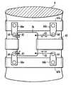
도 1은 본 발명의 제1실시 형태의 초음파 조사 장치의 구성예를 나타내는 평면도이다.BRIEF DESCRIPTION OF THE DRAWINGS It is a top view which shows the structural example of the ultrasonic irradiation apparatus of 1st Embodiment of this invention.
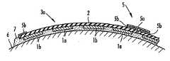
도 2는 도 1의 Ⅱ-Ⅱ선 단면에 대응하여, 제1실시형태의 초음파 조사 장치의 한 사용방법을 나타내는 설명도이다.FIG. 2: is explanatory drawing which shows the usage method of the ultrasonic irradiation apparatus of 1st Embodiment corresponding to the II-II cross section of FIG.
도 3은 도 1의 Ⅱ-Ⅱ선 단면에 대응하여, 제1실시형태의 초음파 조사 장치의 다른 사용방법을 나타내는 설명도이다.FIG. 3 is an explanatory diagram showing another method of using the ultrasonic irradiation apparatus of the first embodiment, corresponding to the section II-II of FIG. 1.
도 4는 본 발명의 제2실시형태의 초음파 조사 장치에 있어서의 제1구성예를 나타내는 평면도이다.It is a top view which shows the 1st structural example in the ultrasonic irradiation apparatus of 2nd Embodiment of this invention.
도 5는 본 발명의 제2실시형태의 초음파 조사 장치에 있어서의 제2구성예를 나타내는 평면도이다.It is a top view which shows the 2nd structural example in the ultrasonic irradiation apparatus of 2nd Embodiment of this invention.
도 6은 본 발명의 제2실시형태의 초음파 조사 장치에 있어서의 제3구성예를 나타내는 평면도이다.It is a top view which shows the 3rd structural example in the ultrasonic irradiation apparatus of 2nd Embodiment of this invention.
도 7은 본 발명의 제2실시형태의 초음파 조사 장치에 있어서의 제4구성예를 나타내는 평면도이다.It is a top view which shows the 4th structural example in the ultrasonic irradiation apparatus of 2nd Embodiment of this invention.
도 8은 본 발명의 제3실시형태의 초음파 조사 장치의 한 구성예를 나타내는 평면도이다.It is a top view which shows an example of a structure of the ultrasonic irradiation apparatus of 3rd Embodiment of this invention.
도 9는 도 8의 Ⅸ-Ⅸ선 단면에 대응하여, 제3실시형태의 초음파 조사 장치의 사용방법을 나타내는 설명도이다.FIG. 9: is explanatory drawing which shows the usage method of the ultrasonic irradiation apparatus of 3rd Embodiment corresponding to the X-ray line cross section of FIG.
도 10은 도 8의 Ⅹ-Ⅹ선 단면에 대응하여, 제3실시형태의 초음파 조사 장치의 사용방법을 나타내는 설명도이다.FIG. 10: is explanatory drawing which shows the usage method of the ultrasonic irradiation apparatus of 3rd Embodiment corresponding to the X-ray line cross section of FIG.
도 11은 본 발명의 제4실시형태의 초음파 조사 장치의 한 구성예를 나타내는 설명적 단면도이다.It is explanatory sectional drawing which shows one structural example of the ultrasonic irradiation apparatus of 4th Embodiment of this invention.
도 12는 도 11의 요부확대 단면도이다.12 is an enlarged cross-sectional view of the main part of FIG. 11.
도 13은 본 발명의 제4실시형태의 초음파 조사 장치의 한 구성예를 나타내는 설명적 단면도이다.It is explanatory sectional drawing which shows one structural example of the ultrasonic irradiation apparatus of 4th Embodiment of this invention.
도 14는 도 13에 나타낸 초음파 조사 장치에 있어서의 초음파 조사자 이동기구의 한 구성예를 나타내는 설명적 단면도이다.It is explanatory sectional drawing which shows an example of a structure of the ultrasonic irradiator moving mechanism in the ultrasonic irradiation apparatus shown in FIG.
도 15는 도 13에 나타낸 초음파 조사 장치에 있어서의 초음파 조사자 이동기구의 다른 구성예를 나타내는 설명적 단면도이다.It is explanatory sectional drawing which shows the other structural example of the ultrasonic irradiator moving mechanism in the ultrasonic irradiation apparatus shown in FIG.
도 16은 도 13에 나타낸 초음파 조사 장치에 있어서의 초음파 조사자 경사기구의 한 구성예를 나타내는 설명적 단면도이다.FIG. 16: is explanatory sectional drawing which shows the structural example of the ultrasonic irradiator inclination mechanism in the ultrasonic irradiation apparatus shown in FIG.
도 17은 본 발명의 제5실시형태의 초음파 조사 장치의 다른 구성예를 나타내는 설명적 단면도이다.It is explanatory sectional drawing which shows the other structural example of the ultrasonic irradiation apparatus of 5th Embodiment of this invention.
도 18은 도17에 나타낸 초음파 조사 장치에 있어서의 초음파 조사자의 경사기구의 한 구성예를 나타내는 설명적 단면도이다.FIG. 18 is an explanatory cross-sectional view showing an example of the configuration of the tilt mechanism of the ultrasonic irradiator in the ultrasonic irradiation device shown in FIG. 17.
도 19는 본 발명의 제5실시형태의 초음파 조사 장치의 또 다른 구성예를 나타내는 설명적 단면도이다.It is explanatory sectional drawing which shows the other structural example of the ultrasonic irradiation apparatus of 5th Embodiment of this invention.
도 20a는 본 발명의 제6실시형태의 초음파 조사 장치의 한 구성예를 나타내는 설명적 단면도이다.It is explanatory sectional drawing which shows one structural example of the ultrasonic irradiation apparatus of 6th Embodiment of this invention.
도 20b는 도 20a의 변형예를 나타내는 설명적 단면도이다.20B is an explanatory cross-sectional view illustrating a modification of FIG. 20A.
도 21은 본 발명의 제6실시형태의 초음파 조사 장치의 바람직한 장착기구를 나타내는 설명도이다.
It is explanatory drawing which shows the preferable mounting mechanism of the ultrasonic irradiation apparatus of 6th Embodiment of this invention.
다음, 첨부도면을 참조하여 본 발명의 실시형태에 대해 더욱 상세하게 설명한다.EMBODIMENT OF THE INVENTION Next, embodiment of this invention is described in detail with reference to an accompanying drawing.
먼저, 도 1 내지 도 3을 참조하여, 본 발명의 제1실시형태의 초음파 조사 장치에 대하여 설명한다.First, with reference to FIGS. 1-3, the ultrasonic irradiation apparatus of 1st Embodiment of this invention is demonstrated.
본 실시형태의 초음파 조사 장치는, 주로 지방 분해 등을 위하여 생체에 초 음파를 조사하기 위해 사용되는 장치에 있어서, 다른 목적, 예를 들어, 혈류의 증가, 경피적 약제의 침투 등에도 사용될 수 있다.The ultrasonic irradiation apparatus of the present embodiment is mainly used for irradiating ultrasonic waves to a living body for lipolysis and the like, and can be used for other purposes, for example, an increase in blood flow, penetration of a percutaneous drug, and the like.
본 실시형태의 초음파 조사 장치는, 도 1에 나타낸 바와 같이, 복수의 초음파 진동자(1a,1b)가 시트체(2)의 일측 표면에 장착되어서, 초음파 조사자(3a)를 구성하고 있다. 또, 초음파 진동자(1a,1b)는, 시트체(2)가 투음성인 경우에는, 시트체(2)의 표리 양면에 알맞게 배열할 수 있다.In the ultrasonic irradiation apparatus of this embodiment, as shown in FIG. 1, the some
초음파 진동자(1a,1b)는, 예를 들면, PZT(Pb(Zr·Ti3)O3) 등의 세라믹스로 이루어지는 압전소자의 일측면에 구동 전극을 설치하고, 타측면에 대향 전극을 설치한 것을 사용할 수 있다. 초음파 진동자(1a,1b)는, 상기 구동 전극과 대향 전극 사이에 소정 주파수의 구동 전압을 인가함에 따라, 초음파를 출력할 수 있다. 초음파 진동자(1a,1b)는, 상기 구동 전극과 대향 전극을 구비하는 2개의 압전소자가, 서로 구동 전극으로 접착되어도 좋다. 본 실시형태에서는, 초음파 진동자(1a,1b)는, 도선(4a,4b)을 매개로 각각 다른 구동계에 접속되어, 예를 들어, 서로 역타이밍으로 ON/OFF 될 수 있다. 물론, 초음파 진동자(1a)의 계통과, 초음파 진동자(1b)의 계통을 분리하지 않고, 모두 동일 구동 조건으로 구동할 수도 있다.The
시트체(2)는, 가요성 및/또는 신축성을 구비한 재료로 이루어지는 것이 바람직하며, 각종 고무제 시트체, 발포 부틸렌, 발포 실리콘과 같은 스폰지상 고무(Foam rubber)제 시트체, 직포, 섬유상 부직포 등을 사용할 수 있다. 시트체(2)는, 가요성 및/또는 신축성을 구비함에 따라, 생체의 복부, 대퇴부, 둔 부, 턱부 등의 3차원적 곡면을 따라 초음파 진동자(1a,1b)를 구성하는 초음파 진동자 개개의 위치를 서로 변경시킬 수 있다. 초음파 진동자(1a,1b)는, 통상적으로, 상기 대향 전극을 접지 전극으로 하여, 해당 접지 전극측으로 생체에 접촉하도록 시트체(2)에 장착된다.The
초음파 조사자(3a)는, 또한, 테두리부에 한 쌍의 면 파스너(예를 들면, 크럴사에서 제조한 '매직 테이프'(등록상표))(5a,5b)로 이루어진 접속부재(5)를 구비하고, 복수의 초음파 조사자(3a)가 접속부재(5)를 매개로 접속할 수 있도록 되어 있다.The
초음파 조사자(3a)에 있어서, 초음파 진동자(1a,1b)의 시트체(2)측에는, 기포 함유재 또는 공기층 등의 에어백층을 설치하고, 초음파 진동자(1a,1b)의 시트체(2)측으로부터 초음파의 방사를 공기에 의해 반사하도록 하는 것이 바람직하다. 이와 같이 하면, 전체 초음파 에너지는, 각 초음파 진동자(1a,1b)에 대하여 시트체(2)와 반대측으로 출력되는 출력면을 형성한다. 이 경우, 초음파 진동자(1a,1b)의 공진 주파수 특성이 예협대역(銳狹帶域)으로 되지만, 초음파 진동자(1a,1b)가 연속파(CW)를 방사하는 한 협대역으로써 충분하다.In the
다만, 초음파 진동자(1a,1b)가 펄스파를 방사하는 경우는, 상기 에어백층 대신에, 적어도 초음파 진동자(1a,1b)의 시트체(2)측에 금속 분말을 혼입한 고무 등의 음향 흡수체층을 설치하고, 주파수 특성을 광대역으로 할 필요가 있다. 상기 에어백층 또는 음향 흡수체층은, 초음파 진동자(1a,1b)의 시트체(2) 측에 적층시켜 설치해도 되고, 시트체(2) 자체에 상기 에어백층 또는 음향 흡수체층으로서의 기능 을 부여하여도 된다. 또한, 초음파 조사자(3a)에 있어서, 초음파 진동자(1a,1b)의 생체측에는, 생체와의 음향 임피던스 정합층, 절연층, 접지 전극층 등을 적층시켜 설치해도 된다.However, when the
또한, 초음파 진동자(1a,1b)의 시트(2)측에, 상기 구동 전극에 적층시키거나 또는 간격을 두어 중첩시켜서, 그 위에 절연층, 도전층을 설치하는 것이 바람직하다. 이와 같이 하면, 상기 도전층을 접지 전위로 하는 것에 의해, 생체로의 누설 전류나 불필요한 외부 전자 복사를 방지할 수 있다. 상기 도전층은, 시트체(2)에 도전성을 부여하는 처리를 실시하거나, 시트체(2)에 알루미늄 섬유포를 적층시켜 설치할 수도 있다.Furthermore, it is preferable to laminate | stack on the drive electrode side of the
또한, 시트체(2)가 각종 고경도 고무재 시트체로 이루어질 때에는, 가요성만을 구비하고, 신축성을 구비하지 않는다. 이러한 경우에는, 도 1에 가상선으로 나타낸 바와 같이, 시트체(2)의 표면에 복수의 선형 홈부(2a)를 형성하는 것이 바람직하다. 시트체(2)는, 상기 선형 홈부(2a)를 형성하는 것에 의해, 선형 홈부(2a)를 따르는 방향으로 변형되었을 때, 선형 홈부(2a)의 상단 테두리가 벌어져서 개구부가 배 형태로 변형함에 따라, 선형 홈부(2a)에 교차하는 방향으로도 용이하게 변형할 수 있게 된다.In addition, when the sheet |
상기 선형 홈부(2a)는, 시트체(2)에 장착되어 있는 초음파 진동자(1a,1b)의 간극에 설치되면 좋으며, 직선 형태로 한정되지 않는다. 또한, 선형 홈부(2a)는, 서로 평행할 필요도 없다. 또한, 선폭도 자유롭게 할 수 있다. 선형 홈부(2a)는, 시트체(2)의 일측 표면으로부터 타측 표면을 향하여 형성되면 좋으며, 타측 표면까 지 관통되지 않아도 좋고 또는 관통되어도 좋다.The
다음, 도 1 및 도 2를 참조하여, 본 실시형태의 초음파 조사 장치의 사용 방법에 대해 설명한다.Next, with reference to FIG. 1 and FIG. 2, the usage method of the ultrasonic irradiation apparatus of this embodiment is demonstrated.
도 2에 나타낸 초음파 조사자(3a)는, 도 1의 Ⅱ-Ⅱ선 단면에 상당하고, 복부, 대퇴부, 둔부, 턱부 등의 생체(6)의 3차원적 곡면을 따라서, 초음파 진동자(1a,1b)가 배치되어 있다. 이 때, 초음파 조사자(3a)는, 한 쌍의 면 파스너(5a,5b)로 이루어지는 접속부재(5)를 개재하여, 인접하는 초음파 조사자(3a)와 접속되어 있고, 생체(6)와의 사이에는 초음파 전달 매체인 유동체층(7)이 형성되어 있다.The
유동체층(7)은, 초음파 진동자(1a,1b)와 생체(6) 사이의 공간을 없애 양자의 음향 결합을 양호하게 하기 위한 음향 결합제로서 작용한다. 유동체층(7)으로서는 젤리 등이 사용된다.The
본 실시형태의 초음파 조사 장치에 의해 사람에게 초음파를 조사하는 경우에는, 초음파 조사자(3a)는, 매회 수세(水洗)해서 소독하는 등의 처리가 필요하다. 그래서, 유동체층(7)에 젤리를 사용할 때에는 해당 젤리를 수용성으로 하는 것이 바람직하다. 또한, 시트체(2)는, 내수성, 내소독약성을 구비하고 있는 것이 바람직하다.When irradiating an ultrasonic wave to a person with the ultrasonic irradiation apparatus of this embodiment, the
또, 본 실시형태의 초음파 조사 장치에서는, 유동체층(7) 대신에, 한천(우무)상의 겔(Gel)재와 같은 연질체층을 개재할 수 있고, 나아가 투음성을 구비하는 시트체(2)와 동일 재료 또는 다른 재료를 개재할 수 있다. 상기 한천상의 겔재로서 는, 예를 들어, 대량의 수분을 함유하는 흡수성 폴리머 등을 들 수 있고, 투음성을 구비하는 시트체(2)로서는 기포를 함유하지 않는 고무 등을 들 수 있다.Moreover, in the ultrasonic irradiation apparatus of this embodiment, instead of the
또한, 유동체층(7)이나 그것에 대신하는 재료는, 보온성체 또는 보냉성체인 것이 바람직하고, 별도로 미리 가열 또는 냉각시켜 사용하는 것에 의해, 생체(6)에 대한 초음파 조사의 효과를 향상시킬 수 있다. 또한, 사람에게 초음파를 조사하는 경우에는, 유동체층(7)이나 그것에 대신하는 재료를 가열 또는 냉각시켜 사용하는 것에 의해, 피조사자의 촉감을 개선할 수 있다.In addition, it is preferable that the
본 실시형태의 초음파 조사 장치에서는, 예컨대, 500㎑, 110mW/㎠ 의 초음파를 방사하는 것에 의해, 생체(6)내의 지방 분해를 행한다. 이 때, 초음파 진동자(1a,1b)로부터 조사되는 초음파의 음장이 생체(6)내에서 중합되면, 상호 간섭 때문에 압력 진폭이 가산되는 부분과 감산되는 부분이 생겨, 압력 진폭이 중첩되는 부분에서는 초음파 조사량이 과대 또는 과소해진다.In the ultrasonic irradiation device of the present embodiment, for example, lipolysis in the living
초음파 조사량이 과대해지면, 그 부분이 발열되기도 하고 조직이 파괴되기도 한다. 그래서, 생체에 대한 초음파 조사량의 기준으로서, 미국 식품의약품국(FDA)에 의해, 서멀 인덱스(TIS), 미케니컬 인덱스(MI)가 정해져 있다. FDA의 기준에 의하면, 생체에 대한 초음파 조사량의 안전영역은, TIS=2, MI=0.3으로 되어 있다.When the amount of ultrasonic radiation is excessive, the part may generate heat or the tissue may be destroyed. Therefore, the thermal index TIS and the mechanical index MI are determined by the US Food and Drug Administration (FDA) as a standard of the ultrasonic irradiation dose to a living body. According to the FDA's standard, the safe area of the ultrasonic irradiation dose to a living body is TIS = 2 and MI = 0.3.
이에, TIS는 서멀인덱스의 연조직용 수치에 있어서, TIS=2라는 것은 ,초음파의 연속 조사에 의해 연조직의 온도가 2℃ 상승하는 것을 나타내고, 생체의 온도가 36℃이면, 38℃로 된다는 것을 의미하며, 감기에도 맞는 온도로 지극히 안전하다.Therefore, TIS in the numerical value for the soft tissue of the thermal index, TIS = 2 means that the temperature of the soft tissue is increased by 2 ℃ by continuous irradiation of ultrasonic waves, and that the temperature of the living body is 38 ℃ when the temperature of the living body is 36 ℃. It is extremely safe at a temperature suitable for colds.
또한, 미케니컬 인덱스는, 캐비테이션에 의해 조직이 파괴되는 정도를 나타 낸다. MI=0.3은, 어떠한 포유류에도 안전한 수준이다.In addition, the mechanical index indicates the extent to which tissue is destroyed by cavitation. MI = 0.3 is safe for any mammal.
본 실시형태의 초음파 조사 장치에서, 생체(6)내의 지방 분해를 위해, 전술한 바와 같이 500㎑, 110mW/㎠ 의 초음파를 조사할 때는, 초음파의 중합에 의해 800mW/㎠ 가 되더라도, TIS=2이하, MI=0.3이하로서, 매우 안전한 범위이다. 통상적으로, 2개의 초음파 진동자의 중첩에서는 2배 즉, 220mW/㎠ 이상으로 되는 것은 아니다. 그러나, 다른 용도에 있어서는, 초음파 진동자(1a,1b)의 음장 중합을 무시할 수 없는 경우가 있다.In the ultrasonic irradiation apparatus of the present embodiment, when irradiating ultrasonic waves of 500 mW and 110 mW /
그래서, 본 실시형태의 초음파 조사 장치에서는, 먼저 도 1에 나타낸 바와 같이, 각각 다른 구동계에 의하여 구동되는 초음파 진동자(1a,1b)를 바둑판 모양으로 배치하고 있다. 이 결과, 초음파 진동자(1a,1b)는, 각각 초음파 진동자(1a) 계통이 형성하는 마름모꼴의 중앙에 초음파 진동자(1b)가 배치되고, 초음파 진동자(1b) 계통이 형성하는 마름모꼴의 중앙에 초음파 진동자(1a)가 배치되도록 되어, 초음파 진동자(1a,1b)의 음장이 불필요하게 중첩되지 않도록 할 수 있다.Therefore, in the ultrasonic irradiation apparatus of this embodiment, as shown in FIG. 1, the
또한, 본 실시형태의 초음파 조사 장치에서는, 각각 다른 구동계에 접속되는 도선(4a,4b)을 매개로, 예를 들어, 초음파 진동자(1a,1b)를 서로 역타이밍으로 ON/OFF 하여 구동하도록 할 수 있다. 이 결과, 초음파 진동자(1a,1b)의 음장중합이 생기는 일은 전혀 없다.In addition, in the ultrasonic irradiation apparatus of the present embodiment, for example, the
또한, 본 실시형태에서는 초음파 진동자(1a,1b)의 음장중합에 의해 초음파 조사량이 과대해지거나 과소해지는 것을 방지하기 위하여, 초음파 진동자(1a,1b)를 서로 역타이밍으로 ON/OFF 하여 구동하는 예를 나타내는 바, 초음파 진동자(1a,1b) 의 어떤 한 쪽을 상시 고정구동으로 하고, 다른 쪽을 이상회로경유(移相回路經由)로서 구동하여 그 위치를 상시 변화시키도록 해도 되고, 다른 쪽의 주파수를 상시 조금씩 변화시키도록 해도 된다.In addition, in this embodiment, in order to prevent the ultrasonic irradiation doses from becoming excessive or excessive by the sound field polymerization of the
이와 같이 하면, 간섭에 의해 압력 진폭이 가산되는 부분과 감산되는 부분이, 생체(6)내에서 항상 이동하는 것으로 되고, 초음파가 조사되는 범위내에서 초음파 조사량이 평균화 된다. 따라서, 초음파 조사량이 과대해지거나 과소해지는 것을 방지할 수 있다. 또한, 조사 목적에 대응하여, 조사 출력면의 출력강도(㎽/㎠) 분포를 균일화 하거나, 주변을 약하게 하여 중앙부를 강하게 하는 높은 평지형 또는 산형으로 할 수 있다.In this way, the part to which the pressure amplitude is added and the subtracted by interference will always move in the living
또한, 전술한 바와 같이, 초음파 진동자(1a,1b)의 구동 방법을 바꾸는 방법 대신에, 각 초음파 진동자(1a,1b)의 출력 배분을 조정하도록 하여도 된다.As described above, instead of changing the driving method of the
각 초음파 진동자(1a,1b)의 출력 배분을 조정하는 방법으로서는, 개개의 초음파 진동자(1a,1b) 또는 단위로 된 복수의 초음파 진동자(1a,1b)를 직렬 또는 병렬로 접속한 것과 임피던스 변환 트랜스를 병렬로 접속하고, 그 2차측에 초음파 진동자(1a,1b)를, 1차측에 구동전원을 접속한다. 상기 임피던스 변환 트랜스를 사용할 때에는, 1차측과 2차측과의 권선 비율을 바꾸거나, 자심(磁心)의 삽입 등으로 결합도를 바꾸는 것에 의해, 개개의 초음파 진동자(1a,1b) 또는 단위로 된 복수의 초음파 진동자(1a,1b)를 직렬 또는 병렬로 접속한 것의 출력 배분을 임의의 비로 할 수 있다.As a method of adjusting the output distribution of each
또는, 개개의 초음파 진동자(1a,1b)와 대략 공진하는 인덕턴스를 개개의 초 음파 진동자(1a,1b)와 직렬로 접속하거나, 또는 단위로 된 복수의 초음파 진동자(1a,1b)를 직렬 또는 병렬로 접속한 것과 대략 공진하는 인덕턴스를 단위로 된 복수의 초음파 진동자(1a,1b)와 직렬로 접속하는 것에 의해서도, 개개의 초음파 진동자(1a,1b) 또는 단위로 된 복수의 초음파 진동자(1a,1b)를 직렬 또는 병렬로 접속한 것의 출력 배분을 조정하는 것이 가능하다. 또한, 상기 인덕턴스를 설치하는 것에 의해, 무효 전력을 줄일 수 있는 효과도 얻을 수 있다. 상기 인덕턴스는, 상기 임피던스 변환 트랜스와 비교해서 소형이고, 개개의 초음파 진동자(1a,1b) 또는 단위로 된 복수의 초음파 진동자(1a,1b)를 직렬 또는 병렬로 접속한 것도 탑재할 수 있다.Alternatively, an inductance that substantially resonates with the individual
또한, 초음파 진동자(1a,1b)의 배열은, 도 1에 나타낸 바둑판 모양의 배열로 한정되는 것은 아니고, 육방최밀형태 등, 임의의 배열로 할 수 있다. 또한, 초음파 진동자(1a,1b)의 형상은, 도 1에 나타낸 원형의 것으로 한정되는 것은 아니고, 사각형, 직사각형 등 자유롭게 할 수 있다.In addition, the arrangement | positioning of the
다음, 도 3을 참조하여, 본 실시형태의 초음파 조사 장치의 다른 사용 방법에 대해 설명한다.Next, another usage method of the ultrasonic irradiation apparatus of this embodiment is demonstrated with reference to FIG.
도 3에 나타낸 방법에 있어서는, 초음파 조사자(3a)는, 시트체(2)의 초음파 진동자(1a,1b)와 반대측 표면에서, 유동체층(7)을 개재하여 생체(6)에 접촉하도록 되어 있다. 이와 같이 할 때에는, 초음파 진동자(1a,1b)로부터 조사되는 초음파는, 시트체(2)로부터 출력되고, 유동체층(7)을 매개로 생체(6)에 전달된다. 따라서, 시트체(2)는, 투음성일 필요가 있고, 기포, 기체, 금속분말과 같은 초음파 반사체나 초음파 흡수체를 함유하지 않는 재료, 예를 들면, 천연 고무, 합성 고무, 실리콘 고무 등의 각종 고무재 시트체 등으로써 구성된다. 상기 초음파 반사체나 초음파 흡수체를 함유하는 재료, 예를 들어, 발포 고무, 발포 플라스틱, 직포, 섬유상 부직포 등은 이 경우 시트체(2)로서 부적당하다.In the method shown in FIG. 3, the
또한, 초음파 진동자(1a,1b)의 시트체(2) 반대측에는, 에어백층(8) 및 전자 차폐층(9)을 설치하고, 초음파 진동자(1a,1b), 에버백층(8) 및 전자 차폐층(9)을 피복하는 보호층(10)을 설치하는 것이 바람직하다. 보호층(10)은, 테두리부로 시트체(2)에 접속되어 자루형태로 된다. 그리고, 보호층(10)은 시트체(2)와의 사이의 자루형 부분에 초음파 진동자(1a,1b), 에어백층(8) 및 전자차폐층(9)을 수용한다. 이 경우, 초음파 조사자(3a)를 접속하는 접속부재(5)(한쌍의 면 파스너(5a,5b))는, 보호층(10)의 테두리에 설치된다.Moreover, the
상기 에어벡층(8)은, 기포를 함유하는 재료, 예를 들면, 발포 폴리에틸렌, 발포 고무 등으로 이루어지는 가요성 시트체가 사용된다. 또한, 전자 차폐층(9)은, 금속박, 금속 메시, 도전 고무 등으로 이루어지는 가요성 시트체가 사용된다. 도 3에 나타낸 초음파 조사 장치에 있어서는, 복수의 전자 차폐층(9)이 서로 접동이 자유롭게 적층되어 배치되어 있다.As the
또한, 보호층(10)으로서는, 각종 고무제 시트체, 발포 부틸렌, 발포 실리콘과 같은 스폰지상 고무제 시트체, 직포, 섬유상 부직포 등을 사용할 수 있다. 보호층(10)은, 소독을 위하여는 방수성인 것이 바람직하다. 보호층(10)의 내부에는, 특히 아무것도 충전할 필요가 없고, 공기가 존재하는 것만이 좋다. 또, 상기 에어벡 층(8)은, 단순히 공기층이어도 좋고, 보호층(10)의 내부에 존재하는 공기로써 에어백층(8)을 대신할 수 있다.As the
도 3에 나타낸 초음파 조사 장치에 의하면, 초음파 조사자(3a)는, 시트체(2)의 초음파 진동자(1a,1b) 반대측 표면에서 생체(6)에 접촉하므로, 생체(6)의 3차원적 곡면을 따라 원활하게 접동할 수 있고, 사람에게 초음파를 조사하는 경우, 피조사자의 촉감을 개선할 수 있다. 또한, 초음파 진동자(1a,1b)가 시트체(2)에 대해서 생체(6) 반대측으로 배치되므로, 시트체(2)에 의해 초음파 진동자(1a,1b)를 보호한다는 효과를 얻을 수도 있다.According to the ultrasonic irradiation apparatus shown in FIG. 3, since the
다음, 도 4 내지 도 7을 참조하여, 본 발명의 제2 실시형태의 초음파 조사 장치에 대해 설명한다.Next, with reference to FIGS. 4-7, the ultrasonic irradiation apparatus of 2nd Embodiment of this invention is demonstrated.
본 실시형태의 초음파 조사 장치는, 도 4에 나타낸 바와 같이, 복수의 초음파 진동자(1a,1b)가 망사체(11)에 장착되고, 평면상태로 배열된 초음파 조사자(3b)를 구성하고 있다. 망사체(11)는, 가요성 및/또는 신축성을 구비하는 재료로 이루어지는 것이 바람직하고, 끈, 밴드, 스프링, 사슬, 서로 회전가능하게 연결된 로드 등 중 적어도 1종의 재료가 매듭(12)으로 체결됨에 의해 형성되어 있다. 또한, 초음파 진동자(1a,1b)는, 망사체(11)의 그물 눈(12)에 바둑판 형태로 배치되어 망사체(1)에 접착되어 있다. 또, 초음파 진동자(1a,1b)의 배열은, 바둑판 모양으로 한정되는 것을 아니다.In the ultrasonic irradiation apparatus of this embodiment, as shown in FIG. 4, the some
망사체(11)를 구성하는 상기 끈으로서는, 나일론 등의 합성수지제계, 고무 선(고무 실), 플라스틱 단섬유 등을 들 수 있다. 또한, 망사체(11)를 구성하는 상 기 밴드로서는, 플라스틱, 고무, 부직포, 포, 매우 얇은 금속박, 스프링, 사슬 등으로 이루어진 것을 들 수 있다.Examples of the string constituting the
상기 망사체(11)는, 도 5에 나타낸 바와 같이, 2개의 종사(13)와, 2개의 횡사(14)로 이루어진 것이어도 좋다. 종사(13)와 횡사(14)는, 교점(15)에서 서로 접착되어도 좋다. 이 경우, 초음파 진동자(1a,1b)는 그 측면에서 종사(13)와 횡사(14)에 접착되어도 좋고, 측면에 도시되지 않은 환형 홈부를 형성하고, 해당 환형 홈부에 도입된 종사(13)와 횡사(14)에 의해 구속되도록 하여도 좋다.As shown in FIG. 5, the
또, 도 5에 있어서는, 종사(13)와 횡사(14)의 관계를 명료하게 하기 위하여, 종사(13)를 점선으로, 횡사(14)를 실선으로 나타냄과 동시에, 종사(13)와 횡사(14)의 존재를 나타내기 위하여, 종사(13)와 횡사(14)를 초음파 진동자(1a,1b)로부터 떨어뜨려 도시하고 있다.In addition, in FIG. 5, in order to clarify the relationship between the engaging 13 and the
또한, 초음파 조사자(3b)는, 도 6에 나타낸 바와 같이, 초음파 진동자(1a,1b)가 복수의 밴드(16)에 장착된 구성으로 되어도 좋다. 복수의 밴드(16)는, 초음파 진동자(1a,1b)가 육방최밀형태로 배치되도록, 도시되지 않은 끈 등에 의해 서로 결합되어 망사체(11)를 형성하고 있다.In addition, as shown in FIG. 6, the
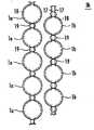
또한, 초음파 조사자(3b)는, 도 7에 나타낸 바와 같이, 초음파 진동자(1a,1b)가 각각 2조의 끈(17)에 의해 결합된 구성으로 되어도 좋다. 2조의 끈(17)은, 초음파 진동자(1a,1b)가 육방최밀형태로 배치되도록, 도시되지 않은 끈 등에 의해 서로 결합되어 망사체(11)를 형성하고 있다. 또, 초음파 진동자(1a,1b)의 배열은 육방최밀형태로 한정되는 것은 아니다.In addition, as shown in FIG. 7, the
이 경우, 초음파 진동자(1a,1b)는 측면에 환형 홈부(18)를 구비하고, 환형 홈부(18)에 도입된 끈(17)에 의해 구속되어 있다. 또한, 2조의 끈(17)은, 초음파 진동자(1a,1a) 사이 또는 초음파 진동자(1b,1b) 사이에 설치된 중공관 형태의 스페이서(19)에 의해 결속되어 있다.In this case, the
또, 도 7에 나타낸 초음파 진동자(3b)에 있어서는, 끈(17)에 대신하여, 가는 밴드, 가는 스프링 등을 사용할 수도 있다.In addition, in the
도 4 내지 도7에 나타낸 초음파 조사자(3b)는, 초음파 진동자(1a,1b)가 망사체(11)에 장착되어 있는 것을 제외한 다른 구성은, 초음파 조사자(3b)와 동일하게 할 수 있다.The
다음, 도 8 내지 도 10을 참조하여, 본 발명의 제3실시형태의 초음파 조사 장치에 대해 설명한다.Next, with reference to FIGS. 8-10, the ultrasonic irradiation apparatus of 3rd Embodiment of this invention is demonstrated.
본 실시형태의 초음파 조사 장치는, 도 8에 나타낸 바와 같이, 시트 형태의 가요성 압전체(21)의 일측면에 형성된 구동 전극(22)과, 타측면에 형성된 대향 전극(23)에 의해 구성되는 복수의 초음파 진동자(1a,1b)가, 평면 상태로 배열되어서, 초음파 조사자(3c)를 구성하고 있다. 초음파 조사자(3c)에 있어서는, 바둑판 눈 형태 배열의 1열씩, 초음파 진동자(1a)와 초음파 진동자(1b)가 교대로 배치되어 있다.As shown in FIG. 8, the ultrasonic irradiation apparatus of this embodiment is comprised by the
가요성 압전체(21)는, PVDF와 같은 유기 압전체를 시트 형태로 형성한 것이나, PZT 등의 세라믹스로 이루어지는 압전재 미립자를 혼련한 플라스틱을 전기장 하에서 시트 형태로 형성한 것 등을 사용할 수 있다. 상기 구동 전극(22) 및 대향 전극(23)은, 시트 형태의 가요성 압전체(21)의 표면에 금속 증착 등의 수단에 의해 형성할 수 있다.The flexible
상기 재료로 이루어지는 가요성 압전체(21)는, 일반적으로 가요성은 구비하고 있으나 신축성은 부족하다. 그래서, 가요성 압전체(21)는, 그 표면에 복수의 선형 홈부(24)를 구비하는 것이 바람직하다. 도 8의 초음파 조사자(3c)에 있어서는, 선형 홈부(24)는, 초음파 진동자(1a,1b)의 간극에 직선상으로 설치되고, 복수의 선형 홈부(24)가 서로 평행하게 형성되어 있다. 또한, 선형 홈부(24)는, 가요성 압전체(21)의 일측 표면으로부터 타측의 표면까지, 가요성 압전체(21)를 두께 방향으로 관통하여 형성되어 있다.The flexible
초음파 조사자(3c)는, 가요성 압전체(21)가 선형 홈부(24)를 구비하는 것에 의해, 해당 선형 홈부(24)를 따르는 방향으로 변형했을 때에, 해당 선형 홈부(24)의 상단 테두리가 벌어져서 개구부가 배 형태로 변형하므로, 해당 선형 홈부(24)에 교차하는 방향으로도 용이하게 변형할 수 있게 된다. 이 결과, 초음파 조사자(3c)에 장착되어 있는 초음파 진동자(1a,1b)의 위치를 서로 3차원적으로 변경이 지유롭게 할 수 있다.The
또, 선형 홈부(24)는, 초음파 진동자(1a,1b)의 간극에 설치되면 좋고, 직선상으로는 한정됨이 없으며, 서로 평행하지 않게 하여도 좋다. 예를 들어, 초음파 진동자(1a,1b)가 육방최밀 형태로 배열되고, 선형 홈부(24)는 초음파 진동자(1a,1b) 사이를 꿰메어 파형 곡선으로 하는 등, 자유롭게 할 수 있다. 또한, 선형 홈부(24)는, 가요성 압전체(21)의 일측 표면으로부터 타측 표면을 향하여 형 성되면 좋고, 관통되지 않아도 좋다. 가요성 압전체(21)를 관통하지 않는 경우, 선형 홈부(24)는 가요성 압전체(21)의 일측 표면과 타측 표면에 교대로 설치되어도 좋다.Moreover, the
또한, 도 8에서는, 선형 홈부(24)는, 가요성 압전체(21)의 일측 표면으로부터 타측 표면까지 관통 형성되어 있기 때문에, 가요성 압전체(21)를 분할하지 않도록, 가요성 압전체(21)의 단부 테두리부에 도달하지 않고, 해당 단부 테두리부에는 선형 홈부(24)가 형성되어 있지 않은 부분이 있다. 그러나, 선형 홈부(24)가 가요성 압전체(21)를 관통하지 않는 경우에는, 선형 홈부(24)는 가요성 압전체(21)의 일측 단부 테두리로부터 대향하는 단부 테두리까지 가요성 압전체(21)를 횡단하여 설치되어도 된다.In FIG. 8, since the
도 8에 도시된 초음파 조사자(3c)는, 초음파 진동자(1a,1b)가 가요성 압전체(21)에 형성되어 있는 것을 제외한 다른 구성은, 초음파 조사자(3a)와 동일하게 할 수 있다.The
다음, 도 9 및 도 10을 참조하여, 본 실시형태의 초음파 조사 장치의 사용 방법에 대하여 설명한다.Next, with reference to FIG. 9 and FIG. 10, the usage method of the ultrasonic irradiation apparatus of this embodiment is demonstrated.
도 9에 나타낸 초음파 조사자(3c)는 도 8의 Ⅸ-Ⅸ선 단면에 상당하고, 도 10에 나타낸 초음파 조사자(3c)는 도 8의 Ⅹ-Ⅹ선 단면에 상당한다. 또, 초음파 진동자(1a,1b)는, 도 8에 나타낸 바와 같이, 실제로는 가요성 압전체(21)의 양면에 설치된 구동 전극(22)과 대향 전극(23)에 의해 구성되어 있지만, 도 9 및 도 10에서는, 도 1의 가요성 시트체의 표면에 초음파 진동자(1a,1b)가 장착되어 있는 경우와 마찬가지로, 가요성 압전체(21)의 한쪽 면에 초음파 진동자(1a,1b)가 설치되어 있는 것과 같이 나타내고 있다.The
본 실시 형태의 초음파 조사 장치에서는, 초음파 조사자(3c)는, 우선 가요성 압전체(21) 자체의 가요성에 의해, 도 9에 나타낸 바와 같이, 선형 홈부(24)를 따르는 방향으로 변형할 수 있다. 또한, 초음파 조사자(3c)는, 상기 변형과 동시에 가요성 압전체(21)에 구비되는 선형 홈부(24)의 개구부가 벌어져서 배형상으로 변형함에 따라, 도 10에 나타낸 바와 같이, 선형 홈부(24)에 교차하는 방향으로 변형할 수 있다.In the ultrasonic irradiation apparatus of this embodiment, the
이 결과, 초음파 조사자(3c)는, 도 9 및 도 10에 나타낸 바와 같이, 3차원적으로 변형할 수 있고, 복부, 대퇴부, 둔부, 턱부 등, 생체(6)의 3차원적 곡면을 따라서 초음파 진동자(1a,1b)가 배치된다. 이 때, 생체(6)와의 사이에는 초음파 전달 매체인 유동체층(7)이 형성되어 있다.As a result, the
그래서, 초음파 조사자(3c)는, 도 9 및 도 10에 나타낸 상태에서 초음파를 조사하는 것에 의해, 생체(6)내의 지방 분해 등을 행한다.Therefore, the
초음파 조사자(3c)는, 가요성 압전체(21)의 생체(6)와 반대측에 보강재층(25)을 구비하고 있어도 좋다. 보강재층(25)은, 기포를 함유하는 가요성 전기 절연재로써 구성할 수 있고, 초음파를 반사하는 에어백층을 겸용하도록 하여도 좋다.The
보강재층(25)은, 가요성 압전체(21)와 반대측의 표면에, 도전체층을 더 설치해서 해당 도전체층을 접지 전위로 하는 것에 의해, 생체로의 누설전류나 불필요한 외부 전자 복사를 방지할 수 있다. 보강재층(25)은, 그 외측에 가요성, 신축성 바로 고무 등의 보호층을 더 설치할 수 있다.The reinforcing
초음파 조사자(3c)는, 또한, 가요성 압전체(21)의 보강재층(25) 반대측 표면과, 생체(6)측 표면 사이에, 도시되지 않은 생체 접촉 시트로 이루어지는 보호층을 구비하여도 좋다. 상기 생체 접촉 시트는, 생체(6)측에 구비될 때에는, 초음파를 투과시킬 수 있도록, 가요성 및/또는 신축성이면서 기포를 함유하는 고무제 시트체와 같은 투음성 재료로 구성된다. 또한, 상기 보호층은, 초음파를 투과시킬 수 있도록, 적어도 초음파 진동자(1a,1b)에 접하는 영역에서는, 가요성 압전체(21)와의 사이에 공기를 함유하지 않도록, 에폭시 수지계 접착제 등으로써 접착시키는 것이 바람직하다.The
상기 각 초음파 조사자(3a,3b,3c)에 있어서, 초음파 진동자(1a,1b)는, 도 1, 도 4 및 도 5에 나타낸 바와 같은 바둑판 형태로 배치되어도 좋고, 도 6 및 도 7에 나타낸 바와 같은 육방최밀 형태로 배치되어도 좋다. 또한, 도 8에 나타낸 바와 같은 바둑판 눈 형태의 배열에 있어서, 초음파 진동자(1a)와 초음파 진동자(1b)를 1열씩 교대로 배치하는 것과 같이 하여도 좋다.In each of the
초음파 진동자(1a,1b)는, 도 6 및 도 7에 나타낸 바와 같은 육방최밀 형태로 배치하는 것에 의해, 초음파 조사자를 생체(6) 표면을 따라 이동시켰을 때, 이동 방향에 상관 없이, 초음파 진동자(1a)의 궤적과, 초음파 진동자(1b)의 궤적이 중합하여, 생체(6)에 있어서 초음파가 조사되지 않는 부분을 없앨 수 있으므로 바람직하다.The
또한, 상기 각 도면에서, 초음파 진동자(1a,1b)는 평면 원형으로 나타내고 있으나, 원형에 한하지 않고, 어떠한 형상으로 형성되어도 무방하다. 도 8에 나타낸 초음파 조사자(3c)는, 초음파 진동자(1a,1b)를 형성하는 구동 전극(22), 대향 전극(23)이 가요성 압전체(21)의 표면에 금속 증착에 의해 설치되므로, 초음파 진동자(1a,1b)를 어떠한 형상으로도 할 수 있고, 평면 원형 이외의 형상으로 하는 경우에 적합하다.In addition, in each said figure, although the
다음, 도 11 및 도 12를 참조하여, 본 발명의 제4실시형태의 초음파 조사 장치에 대해 설명한다.Next, with reference to FIG. 11 and FIG. 12, the ultrasonic irradiation apparatus of 4th Embodiment of this invention is demonstrated.
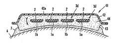
본 실시형태의 초음파 조사 장치는, 도 11에 나타낸 바와 같이, 초음파 조사자(3a)가, 유동체층(7)을 개재하여 가요성 평면상 자루형 바디(31)의 표면에 장착되어 있다. 평면상 자루형 바디(31)는, 가요성과 함께 신축성을 구비하는 유연한 재료로 이루어지고, 초음파 전달 매체인 유동체(32)를 내장하고 있다.In the ultrasonic irradiation apparatus of this embodiment, as shown in FIG. 11, the
본 실시형태의 초음파 조사 장치는, 예를 들어, 평면상 자루형 바디(31)의 표면에 유동체층(7)을 개재하여 생체(6) 등의 피조사체에 접촉시키고, 초음파 조사자(3a)에 의해 평면상 자루형 바디(21)를 매개로 피조사체에 초음파를 조사한다.In the ultrasonic irradiation apparatus of the present embodiment, for example, the surface of the planar bag-shaped
이 때, 본 실시형태의 초음파 조사 장치는, 상기 구성을 구비하고 있으므로, 유동체(32)를 내장하는 평면상 자루형 바디(31)의 두께를 변동시키고, 초음파 조사자(3a)에 장착되어 있는 초음파 진동자(1a,1b)와 피조사체와의 상대적 위치 관계를 변화시킬 수 있다. 따라서, 초음파 진동자(1a,1b)로부터 피조사체에 조사된 초음파가, 피조사체 내에서 중합위치가 변화하고, 특정 부분에만 초음파의 조사량이 과대 또는 과소하게 되는 것을 방지할 수 있다.At this time, since the ultrasonic irradiation apparatus of this embodiment is equipped with the said structure, the ultrasonic wave attached to the
또한, 평면상 자루형 바디(31)는, 초음파 조사자(3a)로부터 분리하여, 전자 렌지로 가열하거나, 냉장고에서 냉각시킬 수도 있다.In addition, the planar bag-shaped
평면상 자루형 바디(31)는, 그 것 자체가 가요성이고, 유동체(32)를 내장하고 있는 것에 의해, 그 두께나 형상을 변화시킬 수 있으며, 더욱 적극적으로 두께나 형상을 변화시키기 위하여, 측면에 외부와 내부를 연통하는 도관(33)을 구비하고, 해당 도관(33)은 도시되지 않은 펌프에 접속시키는 것이 바람직하다.The planar bag-shaped
이와 같이 하면, 상기 펌프(31)에 의해 도관(33)을 매개로 평면상 자루형 바디(31)에 유동체(32)를 공급하거나, 혹은 평면상 자루형 바디(31)로부터 유동체(32)를 배출할 수 있고, 평면상 자루형 바디에 내장되어 있는 유동체(32)의 체적을 빠른 시간 내에 변화시켜 평면상 지루형 바디(31)의 두께나 형상을 변화시킬 수 있다. 또, 상기 「빠른 시간 내에 변화시킴」이라 함은, 임의의 범위의 시간에서, 또는 부정기적으로 변화시키는 것을 포함하고, 정확하게 소정 주기로 변동시키는 것으로 한정하지 않는다.In this way, the fluid 31 is supplied to the
또한, 평면상 자루형 바디(31)에서는, 상기 펌프에 의한 유동체(32)의 공급,배출이나 중력 등의 작용에 의해, 유동체(32)가 평면상 자루형 바디(31) 내에서 부분적으로 치우치게 되고, 혹은 평면상 자루형 바디(31) 내의 유동체(32)의 체적이 과도하게 증대하여, 초음파 조사자(3a)에 장착되어 있는 초음파 진동자(1a,1b)와 피조사체의 거리가 멀어지게 되는 것이다. 나아가, 초음파 조사자(3a)와 평면상 자루형 바디(31)가, 생체(6)의 수직면 등에 적용되면, 유동체(32)는 하방으로 쳐져, 아래가 부풀어 오르고 위가 오므라들며 초음파 조사자(3a)가 급경사져서 생체(6)의 곡면에 접촉하기 어렵게 된다. 그래서, 평면상 자루형 바디(31)는, 그 내부에서 상면측과 하면측을 접속시켜, 평면상 자루형 바디(31)의 두께를 소정의 범위로 계속 유지하는 접속부재(34)를 구비하고 있다.In addition, in the planar bag-shaped
접속부재(34)는, 도 12에 확대해서 나타낸 바와 같이, 평면상 자루형 바디(31)의 하면측 내벽(31a)에 장착된 원통부재(35)와, 평면상 자루형 바디(31)의 상면측 내벽(31b)에 장착되고, 원통부재(35)의 내벽을 따라 접동이 자유로운 원통부재(36)로 이루어진다. 원통부재(36)는 측면에 원호부재(37)를 구비하고, 지면(紙面)의 상하면으로 원통축 방향의 넓은 폭의 절결을 가지며, 원호부재(37)는 원통부재(36)의 탄성변형에 의해 위로부터 원통부재(35)에 삽입되고, 원통부재(35)의 측벽에 구비된 창부(38)로 복원돌출되어 끼워 맞추어져서 접동한다. 그리고, 원호부재(37)가 창부(38)의 상단 테두리(38a)에 걸림에 따라 평면상 자루형 바디(31)의 두께가 그 것 이상으로 되지 않도록 보유지지한다.As enlarged in FIG. 12, the connecting
또한, 본 실시형태의 초음파 조사 장치에 있어서, 평면상 자루형 바디(31)에 내장되어 있는 유동체(32)는, 보온성 또는 보냉성의 유동체로 할 수 있다. 보온성 또는 보냉성의 유동체로 하고, 평면상 자루형 바디(31)를 분리하여 전자 렌지 등으로 유동체(32)를 가열하여 사용하거나, 냉장고 등에서 유동체(32)를 냉각시켜 사용하는 것에 의해, 고온 또는 저온으로 조사할 수 있으므로 피조사체에 대한 초음파 조사의 효과를 향상시킬 수 있다. 또한, 피조사체가 사람인 경우에는, 유동체(32)를 상기와 같이 가열 또는 냉각하여 사용하는 것에 의해, 피조사자의 촉감을 개선시킬 수 있다.Moreover, in the ultrasonic irradiation apparatus of this embodiment, the fluid 32 built in the planar bag-shaped
보온성 유동체(32)로서는, 예를 들어, 물과, 프로필렌 글리콜과, 메틸 셀룰로오스의 혼합물을 사용할 수 있다. 또한, 보냉성 유동체로서는, 예를 들어, 물과, 흡수성 폴리머와, 다가 알콜의 혼합물을 사용할 수 있다.As the
또, 본 실시형태의 초음파 조사 장치는, 도 11에 나타낸 바와 같이, 초음파 조사자(3a)가, 유동체층(7)을 매개로 가요성의 평면상 자루형 바디(31)의 표면에 장착되고, 착탈이 자유롭게 되어 있으나, 초음파 조사자(3a)를 평면상 자루형 바디(31)의 표면에 일체로 설치하여도 된다. 다만, 이 경우에는, 초음파 조사자(3a)에 장착된 초음파 진동자(1a,1b)와, 평면상 자루형 바디(31)와의 사이에 공기가 개재하지 않도록 할 필요가 있다.Moreover, in the ultrasonic irradiation apparatus of this embodiment, as shown in FIG. 11, the
또한, 본 실시형태의 초음파 조사 장치에 있어서는, 도 12에 나타낸 원통부재(35,36)로 이루어지는 접촉부재(34)에 의해, 평면상 자루형 바디(31)의 두께를 소정의 범위로 보유지지하도록 하고 있으나, 이것에 대신하여, 가요성의 가는 조각(Strip), 끈체 등으로써 평면상 자루형 바디(31)의 내부의 서로 대응하는 위치에서 상측면과 하측면을 접속하도록 하여도 된다.Moreover, in the ultrasonic irradiation apparatus of this embodiment, the
또한, 본 실시형태의 초음파 조사 장치에서는, 초음파 조사자(3a) 대신에, 도 4 내지 도 7에 나타낸 초음파 조사자(3b) 또는 도 8에 나타낸 초음파 조사자(3c)를 사용하여도 된다.In addition, in the ultrasonic irradiation apparatus of this embodiment, you may use the
다음, 도 13 내지 도 19를 참조하여, 본 발명의 제5실시 형태의 초음파 조사 장치에 대해 설명한다.Next, with reference to FIGS. 13-19, the ultrasonic irradiation apparatus of 5th Embodiment of this invention is demonstrated.
본 실시형태의 초음파 조사 장치는, 도 13에 나타낸 바와 같이, 초음파 조사 자(3a)가. 가요성의 평면상 자루형 바디(41)의 내부에 설치되어 있다. 평면상 자루형 바디(41)는, 일측면이 강성재료(42)로 이루어짐과 동시에, 강성재료(42)에 대향하는 타측면이 가요성과 함께 신축성을 구비하는 유연재료(43)로 이루어지고, 유연재료(43)에 의해 출력창부가 형성되어 있다. 또한, 평면상 자루형 바디(41)는, 초음파 던달 매체인 유동체(44)를 내장하고 있다. 그래서, 초음파 조사자(3a)는, 도 13에 화살표로 나타낸 바와 같이, 유연재료(43)로 이루어지는 출력창부에 대략 평행한 강성재료(42)의 평면부(42a)를 따라서 이동이 자유롭거나, 또는 평면부(42a)에 대해 경사가 자유롭게 구비되어 있다.As for the ultrasonic irradiation apparatus of this embodiment, as shown in FIG. 13,
본 실시형태의 초음파 조사 장치는, 평면상 자루형 바디(41)를 유연재료(43)로 이루어지는 출력창부측에 유동체층(7)을 개재하여 생체(6) 등의 피조사체에 접촉시키는 바, 초음파 조사자(3a)에 의해 적어도 한면(본 실시형태에서는 유연재료(43))이 가요성의 평면상 자루형 바디(41)를 개재하여 피조사체에 초음파를 조사한다.In the ultrasonic irradiation apparatus of the present embodiment, the planar bag-shaped
평면상 자루형 바디(41)는, 일측의 면이 강성재료(42)로 이루어지므로, 강성재료(42) 측을 보유지지하는 것에 의해 취급이 용이하게 된다.Since the planar bag-shaped
이 때, 본 실시형태의 초음파 조사 장치는, 초음파 조사자(3a)가, 강성재료(42)의 평면부(42a)를 따라서 이동이 자유롭거나, 또는 평면부(42a)에 대해서 경사가 자유롭게 구비되어 있으므로, 초음파 조사자(3a)에 장착되어 있는 초음파 진동자(1a,1b)와 피조사체의 상대적 위치 관계가 변화한다. 따라서, 초음파 진동자(1a,1b)로부터 피조사체로 조사된 초음파가, 피조사체 내에 있어서의 중합 위치가 변화하고, 특정 부분에만 초음파 조사량이 과대 또는 과소해지는 것을 방지할 수 있다.At this time, in the ultrasonic irradiation apparatus of this embodiment, the
또한, 초음파 조사자(3a)가, 강성재료(42)의 평면부(42a)를 따라서 이동이 자유롭거나, 또는 평면부(42a)에 대해서 경사가 자유롭게 구비되어 있음으로써, 초음파 진동자(1a,1b)의 배열에 기인하는 음장의 불균일이 평균화 된다. 따라서, 초음파 조사자(3a)의 이동 또는 요동에 의한 변위 범위는, 초음파 진동자(1a,1b)의 배열 간격 정도인 것이 바람직하다.In addition, the
또한, 본 실시형태의 초음파 조사 장치에서는, 평면상 자루형 바디(41)가 일측의 면에 유연재료(43)를 구비하고 있다. 이와 같은 초음파 조사 장치에 의하면, 유연재료(43)를 개재하여 생체(6) 등의 3차원적 곡면을 가지는 피조사체에 접촉할 수 있다. 따라서, 평면상 자루형 바디(41) 내부에 설치되어 있는 초음파 조사자는, 복수의 초음파 진동자가 강성을 구비하는 시트체의 표면에 장착되어 있는 것이어도 좋다.Moreover, in the ultrasonic irradiation apparatus of this embodiment, the planar bag-shaped
다음, 초음파 조사자(3a)가, 강성재료(42)의 평면부(42a)를 따라서 이동이 자유롭게 또는 평면부(42a)에 대해 경사가 자유롭게 하는 기구에 대해 설명한다.Next, the mechanism by which the
먼저, 초음파 조사자(3a)가, 강성재료(42)의 평면부(42a)를 따라서 이동이 자유롭게 구비되어 있는 경우, 초음파 조사자(3a)는, 도 14에 나타낸 바와 같이, 적어도 3개의 지지부재(45)에 의해 강성재료(42)에 이동이 자유롭게 매달려 있다.First, when the
여기서, 1개의 지지부재(45)는, 수밀 베어링(46)을 개재하여, 평면상 자루형 바디(41)의 외부에 구비된 도시되지 않은 모터의 회전축에 접속되어 회전이 자유롭 게 설치되어 있다. 지지부재(45)의 선단부에는, 원판(47)이 장착되어 있고, 원판(47)의 주연부에 수직하방으로 돌출되어 구비된 핀(48)이 초음파 조사자(3a)에 구비된 가늘고 긴 창부(49a)에 삽입되어 있다. 창부(49a)는 원판(47)의 직경에 상당하는 길이를 구비하고 있다.Here, one
이와 같은 기구에 의하면, 지지부재(45a)의 회전을 따라 핀(48)이 창부(49a)에 끼워맞추어져 초음파 조사자(3a)를 움직이므로, 초음파 조사자(3a)가 강성재료(42)의 평면부(42a)를 따라서 이동이 자유롭게 된다.According to such a mechanism, since the
이 때, 강성재료(42)에, 초음파 조사자(3a)의 테두리부를 창부(49a) 연장 방향과 직교하는 방향으로 지지하는 가이드부재(50)를 설치하여도 좋다. 가이드부재(50)를 설치하면, 초음파 조사자(3a)는 가이드부재(50)에 의해 창부(49a)의 연장방향으로의 이동이 규제되고, 창부(49a)의 연장방향과 직교하는 방향으로 왕복이동한다.At this time, the
또한, 도 15에 나타낸 바와 같이, 초음파 조사자(3a)에 가늘고 긴 창부(49a) 대신에, 핀(48)이 삽입 통과되는 삽통공(49b)을 설치하여도 좋다. 이 경우에는, 지지부재(45a)의 회전을 따라 핀(48)이 삽통공(49b)에 끼워맞추어져 초음파 조사자(3a)를 움직임으로써, 초음파 조사자(3a)는 원판(47)의 원주를 따라서 원운동한다.As shown in FIG. 15, instead of the
다음, 초음파 조사자(3a)가 강성재료(42)의 평면부(42a)에 대해 자유롭게 경사질 수 있도록 되어 있는 경우를 설명한다. 초음파 조가자(3a)는, 도 16에 나타낸 바와 같이, 측면의 대략 중앙부에 회동이 자유로운 지지부재(51)에 의해 강성재료(42)의 측벽에 축지지되어 있다.Next, the case where the
여기서, 강성재료(42)의 측벽에는, 도시되지 않은 수밀 베어링을 개재하여, 평면상 자루형 바디(41)의 외부에 구비된 도시되지 않은 모터에 접속된 회전축(52)이 구비되어 있다. 회전축(52)의 선단에는, 원판(53)이 장착되어 있고, 원판(53)의 테두리부에 수직측 방향으로 돌출되어 구비된 핀(54)이, 초음파 조사자(3a)의 측면에 구비된 가늘고 긴 슬릿부(55)에 삽입되어 있다. 슬릿부(55)는, 원판(53)의 직경에 상당하는 길이를 구비하고 있다.Here, the side wall of the
이와 같은 기구에 의하면, 회전축(52)의 회전을 따라 핀(52)이 슬릿부(55)에 끼워맞추어져서 초음파 조사자(3a)를 움직이므로, 초음파 조사자(3a)의 슬릿부(55)가 설치된 단부가 원판(53)의 직경에 상당하는 길이로 상하 이동한다. 이 때, 초음파 조사자(3a)는 회동이 자유로운 지지부재(51)에 의해 강성재료(42)의 측벽에 축지지되어 있으므로, 지지부재(51)를 기점으로 하여, 강성재료(42)의 평면부(42a)에 대해 경사가 자유롭게 된다.According to such a mechanism, since the
또, 초음파 조사자(3a)는, 도 14 내지 도 16의 기구에 따르지 않고, 선형 모터, 수력 피스톤, 전자이동 솔레노이드, 수력 모터 등으로 구동되고, 강성재료(42)의 평면부(42a)를 따라 이동이 자유롭거나 또는 강성재료(42)의 평면부(42a)에 대해 경사가 자유롭게 되어도 좋다.In addition, the
또한, 초음파 조사자(3a)를 강성재료(42)의 평면부(42a)에 대해 경사가 자유롭게 할 때에는, 도 17에 나타낸 바와 같이, 초음파 조사자(3a)를 복수의 초음파 진동자(1a) 또는 초음파 진동자(1b) 마다 미분된 단위열로 분할한 초음파 조사자(3d)로 하는 것이 바람직하다. 초음파 조사자(3d)에 의하면, 평면부(42a)에 대한 경사각을 초음파 조사자(3a)의 경우 보다도 크게 할 수 있고, 초음파 진동자(1a,1b)로부터 피조사체에 조사된 초음파가, 피조사체 내에 있어서의 중합 위치 변화를 크게할 수 있다.When the
이 때에는, 도 18에 나타낸 바와 같이, 평면상 자루형 바디(41)의 말단부에 위치하는 초음파 조사자(3d)에 대해서, 도 16에 나타낸 기구와 동일한 기구를 설치하고, 해당 초음파 조사자(3d)의 단부를 다른 초음파 조사자(3d)의 단부와 연결부재(56)에 의해 결합한다. 이와 같이 함에 따라, 원판(53)에 설치된 핀(54)이 슬릿부(55)에 끼워맞추어져 있는 초음파 조사자(3d)의 경사에 맞추어서 나머지 초음파 조사자(3a)를 일제히 강성재료(42)의 평면부(42a)에 대해서 기울일 수 있다.At this time, as shown in FIG. 18, the same mechanism as that shown in FIG. 16 is provided for the
또, 도 14 내지 도 16 및 도 18에서는, 초음파 진동자(1a,1b)를 생략하여 나타내고 있다.In addition, in FIGS. 14-16 and 18, the
또한, 본 실시형태의 초음파 조사 장치에서는, 평면상 자루형 바디(41)의 생체(6) 반대측의 면을, 강성재료(42) 대신에, 가요성 재료로 구성할 수도 있다. 상기 가요성 재료는, 일방향으로는 양호한 가요성을 나타내지만, 일방향으로 변형켰을 때, 상기 변형에 교차하는 방향으로 변형이 어렵다.Moreover, in the ultrasonic irradiation apparatus of this embodiment, the surface on the opposite side to the living
그래서, 강성재료(42) 대신에, 약간 단단한 가요성 재료를 사용할 때에는, 도 19에 나타낸 바와 같이, 약간 단단한 가요성 재료(57)을 절곡시켜 파형으로 형성하고, 절곡된 부분을 직선형 홈부(58)로 한다. 이와 같이 함으로써, 평면상 자루형 바디(41)는, 직선형 홈부(58)의 개구부 상단이 벌어져 변형하는 것에 의해, 직 선상 홈부(58)에 교차하는 방향으로도 변형할 수 있다. 직선상 홈부(58) 방향의 생체 곡면에의 적합은, 유연재료(43)로 이루어지는 출력창부의 변형에 의해 행해진다. 도 17의 경우보다, 유연재료(43)로 이루어지는 출력창부의 변형 범위가 적어지는 결과, 유동재(44)의 두께를 작게 할 수 있고, 경량으로 된다.Therefore, when using a slightly hard flexible material instead of the
이 결과, 평면상 자루형 바디(41)는 3차원적으로 변형할 수 있고, 내부에 설치되어 있는 초음파 조사자(3a)에 장착된 초음파 진동자(1a,1b)를 생체(6)의 3차원적 곡면을 따라서 배치할 수 있다.As a result, the planar bag-shaped
도 19에 나타낸 구성에서는, 초음파 조사자(3a)는, 초음파 진동자(1a,1b)로부터 피조사체에 조사된 초음파가 피조사체내에 있어서의 중합 위치를 변화시키고, 동시에 초음파 진동자(1a,1b)의 배열에 의한 음장의 불균일을 평균화 시키기 위하여, 화살표로 나타낸 바와 같이, 유연재료(43)이 생체(6)에 접하는 면을 따라서 이동이 자유롭게 되어 있는 것이 바람직하다. 이를 위해, 초음파 조사자(3a)의 가요성 시트체(2)에 자성체를 혼입하거나, 부설함과 동시에, 직선상 홈부(58)의 저부에 자석이 부설되어 있다.In the structure shown in FIG. 19, the
본 실시형태의 초음파 조사장치에서는, 평면상 자루형 바디(41)에 내장되는 유동체(44)로서, 도 11에 나타낸 평면상 자루형 바디(31) 내장되어 있는 유동체(32)와 동일하게 보온성 또는 보냉성 유동체를 사용할 수 있다. 따라서, 본 실시형태의 초음파 조사장치에서는, 유동체(42)를 전자 렌지 등으로 가열시켜 사용하거나, 냉장고 등에서 냉각시켜 사용하는 것에 의해, 유동체(32)의 경우와 마찬가지로, 피조사체에 대한 초음파 조사 효과를 향상시키고, 피조사체가 사람인 경우에 는 피조사자의 촉감을 개선할 수 있다.In the ultrasonic irradiation apparatus of the present embodiment, the fluid 44 contained in the planar bag-shaped
또한, 본 실시형태의 초음파 조사 장치에서는, 초음파 조사자(3a) 대신에, 도 4 내지 도 7에 나타낸 초음파 조사자(3b) 또는 도 8에 나타낸 초음파 조사자(3c)를 사용하여도 된다.In addition, in the ultrasonic irradiation apparatus of this embodiment, you may use the
다음, 도 20a,b 및 도 21을 참조하여, 본 발명의 제6 실시형태의 초음파 조사 장치에 대해 설명한다. 도 20a,b 및 도 21에서는, 초음파 진동자(1a,1b)를 생략하여 나타내고 있다.Next, with reference to FIG. 20A, FIG. 21 and FIG. 21, the ultrasonic irradiation apparatus of 6th Embodiment of this invention is demonstrated. In FIG. 20A, FIG. 21 and FIG. 21, the
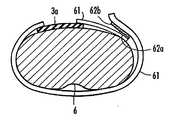
본 실시형태의 초음파 조사 장치는, 도 20a 또는 도 20b에 나타낸 바와 같이, 초음파 조사자(3a)가, 띠상 장착체(61)를 매개로 하여, 복부, 대퇴부 등의 생체(6)에 장착이 자유롭게 설치되어 있다. 따상 장착체(61)는, 도 20a에 나타낸 바와 같이, 초음파 조사자(3a)의 단부에 접속됨과 동시에, 생체(6)에 감겨져서, 한 쌍의 면 파스너(62a,62b)에 의해 적당한 위치에 당겨 묶을 수 있도록 되어 있다.In the ultrasonic irradiation apparatus of this embodiment, as shown in FIG. 20A or 20B, the
또한, 띠상 장착체(61)는, 도 20b에 나타낸 바와 같이, 초음파 조사자(3a)를 피복하도록 되어 있어도 좋다. 이 때, 초음파 조사자(3a)는 띠상 장착체(61)에 일체로 고정되어도 되고, 한 쌍의 면 파스너(도시 생략)에 의해 띠상 장착체(61)에 착탈이 자유롭게 설치되어도 좋다. 또한, 초음파 조사자(3a)는, 따상 장착체(61)에 고정되는 수단을 하나도 구비하지 않고, 단순히 띠상 장착체(61)과의 마찰에 의해 띠상 장착체(61)에 보유지지되어도 무방하다.In addition, as shown in FIG. 20B, the strip-shaped attaching
본 실시형태의 초음파 조사장치는, 초음파 조사자(3a)가 띠상 장착체(61)를 개재하여 생체(6)에 장착되므로, 조작자의 부담을 현저히 감소시킬 수 있다.In the ultrasonic irradiation apparatus of the present embodiment, since the
또한, 초음파 조사자(3a)는, 도 3에 나타낸 바와 같이, 가요성 시트체(2) 측에서 생체(6)에 접촉되도록 하는 것이 바람직하다. 또한, 초음파 조사자(3a)는, 비출력측 배면에 보호층을 설치하고, 그 표면에 불소수지층 등의 마찰계수가 작은 재료를 설치한 띠상 장착체(61)로 미끄럼운동 가능함과 동시에, 유동체층(7)을 매개로 생체(6)에 접촉시켜, 생체(6)와도 미끄럼운동 가능하게 하는 것에 의해, 띠상 장착체(61)와 생체(6) 사이에 개재장착된 채, 생체(6)를 따라 이동시킬 수 있다.In addition, as shown in FIG. 3, it is preferable that the
또한, 본 실시형태의 초음파 조사 장치는, 띠상 장착체(61)와의 마찰을 피해서 개재하는 것이 아니라 생체(6)에 장착된 채, 생체(6)를 따라서 이동이 자유롭게 하기 위하여, 도 21에 나타낸 구성을 구비하는 것이 바람직하다.In addition, the ultrasonic irradiation apparatus of this embodiment is shown in FIG. 21 in order to freely move along the living
도 21에 나타낸 초음파 조사 장치는, 띠상 장착체(61)에 덮혀지지 않고 초음파 조사자(3a)의 단부에 접속됨과 동시에, 생체(6)에 체결되는 띠상 장착체(63)와, 도시되지 않은 모터에 의해 구동되는 풀리(64)에 의해 초음파 조사자(3a)에 접속된 실(65)을 감는 권취장치(66a,66b)를 구비함과 더불어, 생체(6)에 체결되는 띠상 장착체(67a,67b)로 이루어진다. 각 띠상 장착체(63,67a,67b)는, 단부에 도시되지 않은 한 쌍의 면 파스너를 구비하고, 해당 면 파스너에 의해, 적당한 위치에서 생체(6)에 당겨 묶을 수 있도록 되어 있다.The ultrasonic irradiation apparatus shown in FIG. 21 is connected to the end of the
도 21에 나타낸 초음파 조사 장치는, 각 띠상 장착체(63,67a,67b)에 의해, 생체(6)에 장착된 상태에서, 권취장치(66a,66b)를 교대로 구동하는 것에 의해, 초음파 조사장치(3a)를 젤리를 윤활제로 하여 생체(6) 표면을 따라 띠상 장착체(63)의 길이 방향으로 왕복이동할 수 있다.The ultrasonic irradiation apparatus shown in FIG. 21 alternately drives the winding
또, 도 21에 나타낸 초음파 조사 장치는, 초음파 조사자(3a)가 띠상 장착체(63)의 길이 방향을 따라서 왕복이동이 자유롭게 되어 있으나, 띠상 장착체(63)의 폭방향을 따라서 왕복이동이 자유롭게 되어도 좋다.In addition, in the ultrasonic irradiation apparatus shown in FIG. 21, although the
또한, 본 실시형태의 초음파 조사 장치에 있어서, 띠상 장착체(61,63,67a,67b)는, 생체(6)에 장착하기 위하여, 가요성으로, 땀 등이 흡수 또는 투할 수 있는 재료로 이루어지는 것이 바람직하다. 이와 같은 재료로서, 예를 들면, 직포, 부직포 등으로 이루어지는 벨트, 섬유망 등을 들 수 있다.In the ultrasonic irradiation apparatus of the present embodiment, the band-shaped mounting
또한, 본 실시형태의 초음파 조사 장치에서는, 초음파 조사자(3a) 대신에, 도 4 내지 도 7에 나타낸 초음파 조사자(3b), 또는 도 8에 나타낸 초음파 조사자(3c) 또는 도 13 내지 도 19에 나타낸 적어도 한 면을 가요성으로 한 평면상 자루형 바디(41)를 사용해도 좋다.
In addition, in the ultrasonic irradiation apparatus of this embodiment, instead of the
본 발명은, 생체 내의 지방을 분해하기 위하여나 혈류촉진, 약제침투를 위해 생체에 초음파를 조사하는 용도 등으로 이용할 수 있다.INDUSTRIAL APPLICABILITY The present invention can be used for decomposing fat in a living body or for irradiating ultrasonic waves to a living body for promoting blood flow and infiltrating drugs.
Claims (26)
Translated fromKoreanApplications Claiming Priority (3)
| Application Number | Priority Date | Filing Date | Title |
|---|---|---|---|
| JP2000149135 | 2000-05-22 | ||
| JPJP-P-2000-00149135 | 2000-05-22 | ||
| PCT/JP2001/004265WO2001089723A1 (en) | 2000-05-22 | 2001-05-22 | Ultrasonic irradiation apparatus |
Publications (2)
| Publication Number | Publication Date |
|---|---|
| KR20030028472A KR20030028472A (en) | 2003-04-08 |
| KR100730845B1true KR100730845B1 (en) | 2007-06-20 |
Family
ID=18655036
Family Applications (1)
| Application Number | Title | Priority Date | Filing Date |
|---|---|---|---|
| KR1020027015637AExpired - Fee RelatedKR100730845B1 (en) | 2000-05-22 | 2001-05-22 | Ultrasonic irradiation device |
Country Status (8)
| Country | Link |
|---|---|
| US (1) | US7399284B2 (en) |
| EP (1) | EP1312423A4 (en) |
| JP (1) | JP4799795B2 (en) |
| KR (1) | KR100730845B1 (en) |
| CN (1) | CN1234469C (en) |
| BR (1) | BR0111073A (en) |
| CA (1) | CA2410416A1 (en) |
| WO (1) | WO2001089723A1 (en) |
Families Citing this family (91)
| Publication number | Priority date | Publication date | Assignee | Title |
|---|---|---|---|---|
| JP3842188B2 (en)* | 2002-08-28 | 2006-11-08 | 株式会社日立製作所 | Ultrasonic therapy device |
| US20060241522A1 (en)* | 2003-06-18 | 2006-10-26 | Chandraratna Premindra A | Ultrasound devices and methods for treating ischemia and other cardiovascular disorders |
| US20080086056A1 (en)* | 2003-08-25 | 2008-04-10 | Industrial Technology Research Institute | Micro ultrasonic transducers |
| US7741756B2 (en)* | 2003-12-04 | 2010-06-22 | Koninklijke Philips Electronics N.V. | Ultrasound transducer and method for implementing flip-chip two dimensional array technology to curved arrays |
| US7393325B2 (en)* | 2004-09-16 | 2008-07-01 | Guided Therapy Systems, L.L.C. | Method and system for ultrasound treatment with a multi-directional transducer |
| US8444562B2 (en) | 2004-10-06 | 2013-05-21 | Guided Therapy Systems, Llc | System and method for treating muscle, tendon, ligament and cartilage tissue |
| US10864385B2 (en) | 2004-09-24 | 2020-12-15 | Guided Therapy Systems, Llc | Rejuvenating skin by heating tissue for cosmetic treatment of the face and body |
| US8535228B2 (en) | 2004-10-06 | 2013-09-17 | Guided Therapy Systems, Llc | Method and system for noninvasive face lifts and deep tissue tightening |
| US11883688B2 (en) | 2004-10-06 | 2024-01-30 | Guided Therapy Systems, Llc | Energy based fat reduction |
| JP5094402B2 (en) | 2004-10-06 | 2012-12-12 | ガイデッド セラピー システムズ, エル.エル.シー. | Method and system for ultrasonic tissue processing |
| US20060111744A1 (en) | 2004-10-13 | 2006-05-25 | Guided Therapy Systems, L.L.C. | Method and system for treatment of sweat glands |
| US8690779B2 (en) | 2004-10-06 | 2014-04-08 | Guided Therapy Systems, Llc | Noninvasive aesthetic treatment for tightening tissue |
| US9827449B2 (en) | 2004-10-06 | 2017-11-28 | Guided Therapy Systems, L.L.C. | Systems for treating skin laxity |
| US9694212B2 (en) | 2004-10-06 | 2017-07-04 | Guided Therapy Systems, Llc | Method and system for ultrasound treatment of skin |
| US8133180B2 (en) | 2004-10-06 | 2012-03-13 | Guided Therapy Systems, L.L.C. | Method and system for treating cellulite |
| JP2008522642A (en) | 2004-10-06 | 2008-07-03 | ガイデッド セラピー システムズ, エル.エル.シー. | Method and system for beauty enhancement |
| US11235179B2 (en) | 2004-10-06 | 2022-02-01 | Guided Therapy Systems, Llc | Energy based skin gland treatment |
| US11207548B2 (en) | 2004-10-07 | 2021-12-28 | Guided Therapy Systems, L.L.C. | Ultrasound probe for treating skin laxity |
| US11724133B2 (en) | 2004-10-07 | 2023-08-15 | Guided Therapy Systems, Llc | Ultrasound probe for treatment of skin |
| US20060094988A1 (en)* | 2004-10-28 | 2006-05-04 | Tosaya Carol A | Ultrasonic apparatus and method for treating obesity or fat-deposits or for delivering cosmetic or other bodily therapy |
| US7798970B2 (en) | 2004-11-17 | 2010-09-21 | Salutron, Inc | Ultrasonic monitor for measuring blood flow and pulse rates |
| EP1832314B8 (en)* | 2004-12-27 | 2023-07-19 | Chengdu Heuk Medical Equipment Co., Ltd | Quasi-self focusing high intensity and large power ultrasonic transducer |
| US7857775B2 (en)* | 2005-03-15 | 2010-12-28 | Syneron Medical Ltd. | Method for soft tissue treatment |
| WO2006123414A1 (en)* | 2005-05-19 | 2006-11-23 | Techno Link Co., Ltd. | Ultrasonic living body stimulation device |
| KR100639472B1 (en)* | 2005-06-09 | 2006-10-27 | 주식회사 삼화양행 | Frequency characteristic analysis method of piezoelectric body |
| WO2006134754A1 (en)* | 2005-06-13 | 2006-12-21 | Takayuki Saguchi | Ultrasonic wave radiator for treatment |
| KR100639473B1 (en)* | 2005-06-16 | 2006-10-27 | 주식회사 삼화양행 | How to obtain nonlinearly the frequency characteristics according to the temperature change of the piezoelectric body |
| US8764664B2 (en)* | 2005-11-28 | 2014-07-01 | Vizyontech Imaging, Inc. | Methods and apparatus for conformable medical data acquisition pad and configurable imaging system |
| US9107798B2 (en) | 2006-03-09 | 2015-08-18 | Slender Medical Ltd. | Method and system for lipolysis and body contouring |
| US7828734B2 (en) | 2006-03-09 | 2010-11-09 | Slender Medical Ltd. | Device for ultrasound monitored tissue treatment |
| WO2007130526A2 (en)* | 2006-05-02 | 2007-11-15 | U-Systems, Inc. | Ultrasound scanning and ultrasound- assisted biopsy |
| FR2912308B1 (en)* | 2007-02-12 | 2010-07-30 | Alain Kleinsinger | DEVICE FOR THE TREATMENT OF CELLULITE AND GREASY MASSES. |
| CN101104168B (en)* | 2007-07-17 | 2010-11-17 | 东莞市长江超声波机有限公司 | Ultrasonic cylinder |
| CN101396280A (en)* | 2007-09-27 | 2009-04-01 | 重庆融海超声医学工程研究中心有限公司 | Ultrasonic therapy intestinal tract pushing device |
| US20100274161A1 (en)* | 2007-10-15 | 2010-10-28 | Slender Medical, Ltd. | Implosion techniques for ultrasound |
| KR20110091832A (en) | 2008-06-06 | 2011-08-12 | 얼테라, 인크 | Tissue Imaging and Treatment Systems |
| US12102473B2 (en) | 2008-06-06 | 2024-10-01 | Ulthera, Inc. | Systems for ultrasound treatment |
| CA2729654C (en)* | 2008-07-24 | 2016-04-26 | Airbus Operations Limited | Inspection device |
| US20110178541A1 (en)* | 2008-09-12 | 2011-07-21 | Slender Medical, Ltd. | Virtual ultrasonic scissors |
| EP2331207B1 (en) | 2008-10-03 | 2013-12-11 | Mirabilis Medica Inc. | Apparatus for treating tissues with hifu |
| US9050449B2 (en)* | 2008-10-03 | 2015-06-09 | Mirabilis Medica, Inc. | System for treating a volume of tissue with high intensity focused ultrasound |
| US8277741B2 (en)* | 2008-10-28 | 2012-10-02 | Mccabe Colin Adam | Anti-germicidal and/or antimicrobial apparatus for reducing and/or eliminating germs and/or bacteria from the soles of footwear and method for use |
| CA2742067A1 (en)* | 2008-10-30 | 2010-05-27 | Smith & Nephew, Inc. | Apparatus and method for ultrasonic spine treatment |
| CA2748362A1 (en) | 2008-12-24 | 2010-07-01 | Michael H. Slayton | Methods and systems for fat reduction and/or cellulite treatment |
| DE102009049487B4 (en)* | 2009-10-15 | 2015-05-13 | Richard Wolf Gmbh | Electroacoustic transducer |
| US20110166438A1 (en)* | 2009-12-17 | 2011-07-07 | Emerson Jane F | Rf field shaping and attenuation for emai induction elements |
| CA2813000C (en)* | 2010-09-27 | 2018-09-04 | Techtonic Pty Ltd | Undulatory structures |
| DE102010043108A1 (en) | 2010-10-29 | 2012-05-03 | Robert Bosch Gmbh | Piezoelectric surface acoustic transducer |
| GB2491366A (en) | 2011-05-31 | 2012-12-05 | Nokia Corp | A configurable microphone or loudspeaker apparatus |
| US9669239B2 (en) | 2011-07-27 | 2017-06-06 | Universite Pierre Et Marie Curie (Paris 6) | Device for treating the sensory capacity of a person and method of treatment with the help of such a device |
| CA2845044C (en)* | 2011-08-12 | 2023-03-28 | Jointvue, Llc | 3-d ultrasound imaging device and methods |
| KR101365035B1 (en)* | 2012-02-24 | 2014-02-21 | 조성찬 | ultrasound patch |
| WO2013170053A1 (en)* | 2012-05-09 | 2013-11-14 | The Regents Of The University Of Michigan | Linear magnetic drive transducer for ultrasound imaging |
| FR2991807B1 (en)* | 2012-06-06 | 2014-08-29 | Centre Nat Rech Scient | DEVICE AND METHOD FOR FOCUSING PULSES |
| GB201214273D0 (en) | 2012-08-09 | 2012-09-26 | Airbus Uk Ltd | .Improvements to radius inspection tools |
| US9510802B2 (en) | 2012-09-21 | 2016-12-06 | Guided Therapy Systems, Llc | Reflective ultrasound technology for dermatological treatments |
| JP6306048B2 (en)* | 2012-12-28 | 2018-04-04 | コーニンクレッカ フィリップス エヌ ヴェKoninklijke Philips N.V. | Acoustic probe having components of acoustic elements having different pitches |
| JP6003671B2 (en)* | 2013-01-22 | 2016-10-05 | 株式会社典雅 | Massage device, manufacturing method thereof, and manufacturing apparatus |
| CN104027893B (en) | 2013-03-08 | 2021-08-31 | 奥赛拉公司 | Apparatus and method for multifocal ultrasound therapy |
| WO2015160708A1 (en) | 2014-04-18 | 2015-10-22 | Ulthera, Inc. | Band transducer ultrasound therapy |
| WO2016075586A1 (en)* | 2014-11-14 | 2016-05-19 | Koninklijke Philips N.V. | Ultrasound device for sonothrombolysis therapy |
| WO2016097867A2 (en)* | 2014-12-19 | 2016-06-23 | Université Pierre Et Marie Curie (Paris 6) | Implantable ultrasound generating treating device for brain treatment, apparatus comprising such device and method implementing such device |
| JP6857616B2 (en)* | 2015-05-11 | 2021-04-14 | コーニンクレッカ フィリップス エヌ ヴェKoninklijke Philips N.V. | Deformable ultrasonic arrays and systems |
| ES2939604T3 (en) | 2016-01-18 | 2023-04-25 | Ulthera Inc | Compact ultrasonic device having an annular ultrasonic array peripherally electrically connected to a flexible printed circuit board |
| US11253729B2 (en) | 2016-03-11 | 2022-02-22 | Sorbonne Universite | External ultrasound generating treating device for spinal cord and/or spinal nerve treatment, apparatus comprising such device and method |
| WO2017153798A1 (en) | 2016-03-11 | 2017-09-14 | Université Pierre Et Marie Curie (Paris 6) | Implantable ultrasound generating treating device for spinal cord and/or spinal nerve treatment, apparatus comprising such device and method |
| AU2017278615B2 (en)* | 2016-06-06 | 2022-06-16 | Sofwave Medical Ltd. | Ultrasound transducer and system |
| PL3981466T3 (en) | 2016-08-16 | 2023-11-20 | Ulthera, Inc. | Systems and methods for cosmetic ultrasound treatment of skin |
| CN108652706B (en)* | 2017-03-31 | 2020-09-15 | 宝健科技股份有限公司 | shock head structure |
| CN107789751A (en)* | 2017-11-06 | 2018-03-13 | 复旦大学 | A kind of ultrasonic two-dimensional array treatment band |
| TWI797235B (en) | 2018-01-26 | 2023-04-01 | 美商奧賽拉公司 | Systems and methods for simultaneous multi-focus ultrasound therapy in multiple dimensions |
| CN111771040A (en) | 2018-02-08 | 2020-10-13 | 斯伦贝谢技术有限公司 | Ultrasonic acoustic sensor for measuring formation velocity |
| CN111742243B (en)* | 2018-02-08 | 2024-06-04 | 斯伦贝谢技术有限公司 | Ultrasonic transducer for measuring formation velocity |
| US11944849B2 (en) | 2018-02-20 | 2024-04-02 | Ulthera, Inc. | Systems and methods for combined cosmetic treatment of cellulite with ultrasound |
| CN108354812A (en)* | 2018-03-15 | 2018-08-03 | 彭志军 | A kind of ultrasonic wave massage gas assists device |
| US11346213B2 (en) | 2018-05-14 | 2022-05-31 | Schlumberger Technology Corporation | Methods and apparatus to measure formation features |
| EP3829713B1 (en) | 2018-08-02 | 2025-10-01 | Sofwave Medical Ltd. | System for fat tissue treatment |
| CN109589507A (en)* | 2018-12-13 | 2019-04-09 | 清华大学 | The flexible ultrasonic instrument of biomaterial surface reparation |
| GB2582562B (en)* | 2019-03-22 | 2021-07-21 | Novosound Ltd | Ultrasonic device |
| KR20210007912A (en)* | 2019-07-11 | 2021-01-20 | 엘지전자 주식회사 | Wearable Device |
| US12377293B2 (en) | 2019-07-15 | 2025-08-05 | Ulthera, Inc. | Systems and methods for measuring elasticity with imaging of ultrasound multi-focus shearwaves in multiple dimensions |
| JP7396693B2 (en)* | 2019-08-14 | 2023-12-12 | テイクティ有限会社 | Vibration generator |
| EP3818940A1 (en)* | 2019-11-05 | 2021-05-12 | Koninklijke Philips N.V. | Ultrasound transducer array |
| KR102281777B1 (en)* | 2019-12-12 | 2021-07-26 | (주) 아이엔아이테크 | Heating element using ultrasonic vibration |
| KR102281780B1 (en)* | 2019-12-12 | 2021-07-26 | (주) 아이엔아이테크 | Heat collecting structure using ultrasonic vibration |
| DE102020202275A1 (en) | 2020-02-21 | 2021-08-26 | Atlas Elektronik Gmbh | Water-borne sound converter |
| JPWO2021182615A1 (en)* | 2020-03-13 | 2021-09-16 | ||
| WO2021234214A1 (en)* | 2020-05-18 | 2021-11-25 | Innotia Eesti Oü | System for ultrasound treatment combined with uvc teatment |
| FR3113946B1 (en)* | 2020-09-07 | 2022-07-29 | Grtgaz | CONFORMABLE ULTRASOUND NON-DESTRUCTIVE INSTANT TESTING DEVICE |
| CN116803216A (en) | 2020-12-31 | 2023-09-22 | 苏维夫医疗有限公司 | Cooling of multiple ultrasonic exciters mounted on multiple printed circuit boards |
| KR102732534B1 (en)* | 2022-03-25 | 2024-11-19 | 재단법인대구경북과학기술원 | Patch with detachable and individually controllable ultrasound sensors |
Citations (2)
| Publication number | Priority date | Publication date | Assignee | Title |
|---|---|---|---|---|
| KR200175618Y1 (en)* | 1999-10-11 | 2000-03-15 | 현진전자주식회사 | A skin massage apparatus |
| KR200193637Y1 (en)* | 2000-03-04 | 2000-08-16 | 주식회사정훈기공 | Supersonic waves and ion massager |
Family Cites Families (29)
| Publication number | Priority date | Publication date | Assignee | Title |
|---|---|---|---|---|
| US3552382A (en)* | 1968-01-11 | 1971-01-05 | Hoffmann La Roche | Ultrasonic transducer assembly for biological inspections |
| US3603921A (en)* | 1968-12-18 | 1971-09-07 | Magnavox Co | Sound transducer |
| US3964014A (en)* | 1974-10-15 | 1976-06-15 | General Electric Company | Sonic transducer array |
| JPS54162591A (en)* | 1978-06-13 | 1979-12-24 | Japan Radio Co Ltd | Method of making semicylindrical ultrasonic vibrator |
| US4276491A (en)* | 1979-10-02 | 1981-06-30 | Ausonics Pty. Limited | Focusing piezoelectric ultrasonic medical diagnostic system |
| DE3109040A1 (en)* | 1981-03-10 | 1982-09-30 | Siemens AG, 1000 Berlin und 8000 München | ULTRASONIC APPLICATOR |
| US4446395A (en)* | 1981-12-30 | 1984-05-01 | Technicare Corporation | Short ring down, ultrasonic transducer suitable for medical applications |
| BR8506430A (en)* | 1984-04-03 | 1986-04-15 | Health Lab Service Board | PROCESS TO DETERMINE THE AMOUNT OF BIOLOGICAL MATERIA CONTAINED IN A FLUID MEDIA, PROCESS AND APPARATUS TO MEASURE THE CONCENTRATION OF BIOLOGICAL PARTICLES IN A FLOWING MEDIA AND PROBE FOR USE IN MEASURING THE QUANTITY OF BIOLOGICAL MATERIA IN A FLUID MEDIUM |
| JPS6133585U (en)* | 1984-07-30 | 1986-02-28 | 敬介 本多 | Variable directivity angle transducer |
| EP0181506B1 (en) | 1984-10-15 | 1991-08-21 | Edo Corporation/Western Division | Flexible piezoelectric transducer assembly |
| US4733379A (en)* | 1984-10-15 | 1988-03-22 | Edo Corporation/Western Division | Line array transducer assembly |
| JPS63156618U (en)* | 1987-03-31 | 1988-10-14 | ||
| FR2614747B1 (en)* | 1987-04-28 | 1989-07-28 | Dory Jacques | ELASTIC PULSE GENERATOR HAVING A PREDETERMINED WAVEFORM AND ITS APPLICATION TO TREATMENT OR MEDICAL DIAGNOSIS |
| US4965532A (en)* | 1988-06-17 | 1990-10-23 | Olympus Optical Co., Ltd. | Circuit for driving ultrasonic transducer |
| US5078144A (en)* | 1988-08-19 | 1992-01-07 | Olympus Optical Co. Ltd. | System for applying ultrasonic waves and a treatment instrument to a body part |
| JPH0722264Y2 (en)* | 1988-09-06 | 1995-05-24 | セルコム株式会社 | Ultrasonic therapy device |
| EP0391378B1 (en)* | 1989-04-07 | 1994-11-02 | Kabushiki Kaisha Toshiba | Shock wave lithotrity apparatus using ultrasonic waves |
| US5166573A (en) | 1989-09-26 | 1992-11-24 | Atochem North America, Inc. | Ultrasonic contact transducer and array |
| US6023632A (en)* | 1997-07-16 | 2000-02-08 | Wilk; Peter J. | Ultrasonic medical system and associated method |
| FI930259L (en)* | 1992-11-06 | 1994-05-07 | Takiron Co | Polymert piezoelectric material |
| JP3860227B2 (en)* | 1993-03-10 | 2006-12-20 | 株式会社東芝 | Ultrasonic therapy device used under MRI guide |
| US5792058A (en)* | 1993-09-07 | 1998-08-11 | Acuson Corporation | Broadband phased array transducer with wide bandwidth, high sensitivity and reduced cross-talk and method for manufacture thereof |
| GB2282931B (en) | 1993-10-16 | 1997-11-12 | Atomic Energy Authority Uk | Flexible transducer array support |
| US5810009A (en)* | 1994-09-27 | 1998-09-22 | Kabushiki Kaisha Toshiba | Ultrasonic probe, ultrasonic probe device having the ultrasonic probe, and method of manufacturing the ultrasonic probe |
| JPH08126649A (en)* | 1994-10-31 | 1996-05-21 | Toshiba Corp | Ultrasonic therapy equipment |
| US5619999A (en)* | 1995-12-28 | 1997-04-15 | Siemens Medical Systems, Inc. | Body surface position locator for ultrasound transducer |
| US6007499A (en)* | 1997-10-31 | 1999-12-28 | University Of Washington | Method and apparatus for medical procedures using high-intensity focused ultrasound |
| US6575956B1 (en)* | 1997-12-31 | 2003-06-10 | Pharmasonics, Inc. | Methods and apparatus for uniform transcutaneous therapeutic ultrasound |
| ES2234249T3 (en)* | 1998-03-26 | 2005-06-16 | Exogen, Inc. | FLEXIBLE TRANSDUCER ELEMENTS MATRIX. |
- 2001
- 2001-05-22KRKR1020027015637Apatent/KR100730845B1/ennot_activeExpired - Fee Related
- 2001-05-22JPJP2001585952Apatent/JP4799795B2/ennot_activeExpired - Fee Related
- 2001-05-22BRBR0111073-0Apatent/BR0111073A/ennot_activeApplication Discontinuation
- 2001-05-22WOPCT/JP2001/004265patent/WO2001089723A1/enactiveApplication Filing
- 2001-05-22CNCNB018099165Apatent/CN1234469C/ennot_activeExpired - Fee Related
- 2001-05-22EPEP01932191Apatent/EP1312423A4/ennot_activeWithdrawn
- 2001-05-22USUS10/296,039patent/US7399284B2/ennot_activeExpired - Fee Related
- 2001-05-22CACA002410416Apatent/CA2410416A1/ennot_activeAbandoned
Patent Citations (2)
| Publication number | Priority date | Publication date | Assignee | Title |
|---|---|---|---|---|
| KR200175618Y1 (en)* | 1999-10-11 | 2000-03-15 | 현진전자주식회사 | A skin massage apparatus |
| KR200193637Y1 (en)* | 2000-03-04 | 2000-08-16 | 주식회사정훈기공 | Supersonic waves and ion massager |
Also Published As
| Publication number | Publication date |
|---|---|
| EP1312423A4 (en) | 2005-08-31 |
| BR0111073A (en) | 2004-02-25 |
| WO2001089723A1 (en) | 2001-11-29 |
| US20030135135A1 (en) | 2003-07-17 |
| JP4799795B2 (en) | 2011-10-26 |
| CN1430538A (en) | 2003-07-16 |
| KR20030028472A (en) | 2003-04-08 |
| CN1234469C (en) | 2006-01-04 |
| EP1312423A1 (en) | 2003-05-21 |
| CA2410416A1 (en) | 2002-11-21 |
| US7399284B2 (en) | 2008-07-15 |
Similar Documents
| Publication | Publication Date | Title |
|---|---|---|
| KR100730845B1 (en) | Ultrasonic irradiation device | |
| US11207547B2 (en) | Probe for ultrasound tissue treatment | |
| ES2907588T3 (en) | Systems and methods for the cosmetic treatment of the skin with ultrasound | |
| KR101365946B1 (en) | High intensity focused ultrasound generating device for the deduction of fat tissue | |
| EP2279699B1 (en) | Method for non-invasive cosmetic enhancement of cellulite | |
| US20060074314A1 (en) | Method and system for noninvasive mastopexy | |
| US20120136282A1 (en) | Method and apparatus for treatment of adipose tissue | |
| KR102393045B1 (en) | Skin Treatment Handpiece | |
| KR101356437B1 (en) | High intensity focused ultrasound generating device for deduction of fat tissue | |
| KR102370845B1 (en) | Multi-function skin care device | |
| CN112274787A (en) | Surface focusing ultrasonic transducer array and transducer thereof | |
| CN214318872U (en) | Surface focusing ultrasonic transducer array and transducer thereof | |
| US20240342509A1 (en) | Device for applying ultrasound to superficial targets | |
| RU2800076C2 (en) | Systems and methods of simultaneous multi-focus ultrasound therapy at multiple points | |
| KR20250097207A (en) | Body cavity insertion type focused ultrasound device |
Legal Events
| Date | Code | Title | Description |
|---|---|---|---|
| E13-X000 | Pre-grant limitation requested | St.27 status event code:A-2-3-E10-E13-lim-X000 | |
| PA0105 | International application | St.27 status event code:A-0-1-A10-A15-nap-PA0105 | |
| P11-X000 | Amendment of application requested | St.27 status event code:A-2-2-P10-P11-nap-X000 | |
| P13-X000 | Application amended | St.27 status event code:A-2-2-P10-P13-nap-X000 | |
| PG1501 | Laying open of application | St.27 status event code:A-1-1-Q10-Q12-nap-PG1501 | |
| A201 | Request for examination | ||
| P11-X000 | Amendment of application requested | St.27 status event code:A-2-2-P10-P11-nap-X000 | |
| P13-X000 | Application amended | St.27 status event code:A-2-2-P10-P13-nap-X000 | |
| PA0201 | Request for examination | St.27 status event code:A-1-2-D10-D11-exm-PA0201 | |
| E701 | Decision to grant or registration of patent right | ||
| PE0701 | Decision of registration | St.27 status event code:A-1-2-D10-D22-exm-PE0701 | |
| PR1002 | Payment of registration fee | St.27 status event code:A-2-2-U10-U12-oth-PR1002 Fee payment year number:1 | |
| GRNT | Written decision to grant | ||
| PR0701 | Registration of establishment | St.27 status event code:A-2-4-F10-F11-exm-PR0701 | |
| PG1601 | Publication of registration | St.27 status event code:A-4-4-Q10-Q13-nap-PG1601 | |
| FPAY | Annual fee payment | Payment date:20100610 Year of fee payment:4 | |
| PR1001 | Payment of annual fee | St.27 status event code:A-4-4-U10-U11-oth-PR1001 Fee payment year number:4 | |
| LAPS | Lapse due to unpaid annual fee | ||
| PC1903 | Unpaid annual fee | St.27 status event code:A-4-4-U10-U13-oth-PC1903 Not in force date:20110615 Payment event data comment text:Termination Category : DEFAULT_OF_REGISTRATION_FEE | |
| PC1903 | Unpaid annual fee | St.27 status event code:N-4-6-H10-H13-oth-PC1903 Ip right cessation event data comment text:Termination Category : DEFAULT_OF_REGISTRATION_FEE Not in force date:20110615 |