KR100730839B1 - The display device, signal transmitting/receiving device and radio transmitting device - Google Patents
The display device, signal transmitting/receiving device and radio transmitting deviceDownload PDFInfo
- Publication number
- KR100730839B1 KR100730839B1KR1020000051936AKR20000051936AKR100730839B1KR 100730839 B1KR100730839 B1KR 100730839B1KR 1020000051936 AKR1020000051936 AKR 1020000051936AKR 20000051936 AKR20000051936 AKR 20000051936AKR 100730839 B1KR100730839 B1KR 100730839B1
- Authority
- KR
- South Korea
- Prior art keywords
- signal
- electronic device
- control
- control signal
- audio
- Prior art date
- Legal status (The legal status is an assumption and is not a legal conclusion. Google has not performed a legal analysis and makes no representation as to the accuracy of the status listed.)
- Expired - Fee Related
Links
Images

Classifications
- G—PHYSICS
- G09—EDUCATION; CRYPTOGRAPHY; DISPLAY; ADVERTISING; SEALS
- G09G—ARRANGEMENTS OR CIRCUITS FOR CONTROL OF INDICATING DEVICES USING STATIC MEANS TO PRESENT VARIABLE INFORMATION
- G09G5/00—Control arrangements or circuits for visual indicators common to cathode-ray tube indicators and other visual indicators
- H—ELECTRICITY
- H04—ELECTRIC COMMUNICATION TECHNIQUE
- H04N—PICTORIAL COMMUNICATION, e.g. TELEVISION
- H04N5/00—Details of television systems
- H04N5/38—Transmitter circuitry for the transmission of television signals according to analogue transmission standards
- H—ELECTRICITY
- H04—ELECTRIC COMMUNICATION TECHNIQUE
- H04N—PICTORIAL COMMUNICATION, e.g. TELEVISION
- H04N7/00—Television systems
- H04N7/20—Adaptations for transmission via a GHz frequency band, e.g. via satellite
Landscapes
- Engineering & Computer Science (AREA)
- Multimedia (AREA)
- Signal Processing (AREA)
- Physics & Mathematics (AREA)
- General Physics & Mathematics (AREA)
- Astronomy & Astrophysics (AREA)
- Computer Hardware Design (AREA)
- Theoretical Computer Science (AREA)
- Two-Way Televisions, Distribution Of Moving Picture Or The Like (AREA)
- Selective Calling Equipment (AREA)
Abstract
Translated fromKoreanDescription
Translated fromKorean도 1은 본 발명의 무선 전송장치의 바람직한 실시형태를 도시하는 구성도.1 is a configuration diagram showing a preferred embodiment of the wireless transmission device of the present invention.
도 2는 종래의 무선 전송장치의 한 예를 도시하는 구성도.2 is a configuration diagram showing an example of a conventional radio transmitter.
(도면의 주요부분에 대한 부호의 설명)(Explanation of symbols for the main parts of the drawing)
100 : 무선 전송장치 200 : 신호 송수신장치100: wireless transmission device 200: signal transceiver
205 : 셀렉터부 210, 325 : 제어부205:
250, 310 : 안테나 281, 282, 283 : 전자기기250, 310:
300 : 표시장치 355 : 컨트롤 신호 수신부300: display device 355: control signal receiver
360 : 표시부 370 : 음성 출력부360: display unit 370: audio output unit
AS : 음성신호 VS : 영상신호AS: Audio Signal VS: Video Signal
CS : 컨트롤 신호
CS: control signal
본 발명은 표시장치, 표시 제어장치 및 무선 전송장치의 개량, 특히, 텔레비젼 수상기, 액정 디스플레이 등의 표시장치, 표시 제어장치 및 무선 전송장치에 관한 것이다.BACKGROUND OF THE
(종래의 기술)(Conventional technology)
도 2는, 종래의 무선 전송장치의 일예를 도시하는 구성도이며, 도 2를 참조하여 무선 전송장치(1)에 관해서 설명한다.FIG. 2 is a configuration diagram showing an example of a conventional radio transmitter, and the
도 2의 무선 전송장치(1)는 신호 송신장치(1A)와 신호 수신장치(1B)를 구비하고 있으며, 신호 송신장치(1A)는 신호처리부(2), 변조부(3), 주파수 변환부(4), 주파수 신시사이저부(synthesizer; 5), 전력 증폭부(6), 송신 안테나(7) 등으로 구성되어 있다.The
신호처리부(2)는 버퍼 증폭기나 필터 등으로 구성되어 있고, 전자기기(8a 내지 8c)로부터 보내어진 영상신호(VS) 및 음성신호(AS)를 변조에 알맞는 진폭치로 변환하는 것이다.The
여기서, 전자기기(8a, 8b, 8c)는 예를 들어, 비디오 테이프 리코더, 광 디스크장치, 디지털 CS 튜너(digital control signal tuner)등으로서, 각각 셀렉터부(9)에 대하여 영상신호(VS) 및 음성신호(AS)를 출력하는 것이다. 또한, 셀렉터부(9)는 각 전자기기(8a 내지 8c)중, 어느 하나의 전자기기(8a 내지 8c)를 선택하고, 선택된 전자기기(8a 내지 8c)로부터 출력되는 영상신호(VS) 및 음성신호(AS)를 신호처리부(2)에 출력하는 것이다.Here, the
변조부(3)는 주파수 신시사이저부(5)로부터 보내어진 IF(중간 주파) 신호의 주파수에 기초하여 반송파에 변조를 시키는 것이다. 주파수 변환부(4)는 변조부(3)로부터 보내어진 IF신호를, 주파수 신시사이저부(5)로부터 보내어진 국부발신 주파수와 혼합시켜 RF신호를 생성하는 것이다.The
전력 증폭부(6)는 주파수 변환부(4)로부터 보내여진 RF신호를 규정의 전력으로 증폭하는 것이다. 송신 안테나(7)는 증폭된 RF신호를 외부로 송신하는 기능을 가지고 있다. 즉, 송신 안테나(7)는 RF신호로 변환된 음성신호(AS) 및 영상신호(VS)를 외부로 송신하는 것이다.The
한편, 신호 수신장치(1B)는 수신 안테나(10), 저잡음 증폭부(11), 주파수 변환부(12), 복조부(13), 주파수 신시사이저부(14), 신호처리부(15) 등으로 구성되어 있다. 수신 안테나(10)는 안테나(7)로부터 보내여진 RF신호를 수신하는 것이고, 저잡음 증폭부(11)는 수신된 RF신호를 증폭하는 기능을 가지고 있다. 주파수 변환부(12)는 증폭된 RF신호를 주파수 신시사이저부(14)로부터 보내어진 국부발신 주파수를 혼합하여 IF신호로 변환하는 것이다.On the other hand, the
복조부(13)는 IF신호를 주파수 신시사이저부(14)로부터 공급되는 주파수의 반송파를 이용 복조하여 음성신호(AS) 및 영상신호(VS)로 변환하는 기능을 가지고 있다. 신호처리부(15)는 음성신호(AS) 및 영상신호(VS)에 포함되는 잡음을 제거함과 동시에 증폭하여 표시장치(20)로 보낸다. 표시장치(20)는 예를 들어, 텔레비젼 수상기나 LCD 디스플레이장치로서, 영상신호(VS)에 기초하여 영상을 출력하고, 음성신호(AS)에 기초하여 음성을 출력하는 기능을 가지고 있다.The
다음에, 도 2를 참조하여 종래의 무선 전송장치(1)의 동작 예에 관해서 설명 한다.Next, an operation example of the
우선, 전자기기(8a, 8b, 8c)로부터 영상신호(VS) 및 음성신호(AS)가 셀렉터부(9)로 출력된다. 그리고, 셀렉터부(9)에 의해 선택된 전자기기(8a 내지 8c)중 어느 하나의 영상신호(VS) 및 음성신호(AS)가 신호처리부(2)로 보내진다. 그러면, 영상신호(VS) 및 음성신호(AS)는 신호처리부(2), 변조부(3) 및 주파수 변환부(4)를 통하여 RF신호로 변환된다. 그리고, 이 RF신호가 전력 증폭부(6)에서 증폭되어 안테나(7)로부터 전파로서 출력된다.First, the video signal VS and the audio signal AS are output from the
출력된 RF신호는 안테나(10)에 의해 수신되고, 저잡음 증폭부(11), 주파수 변환부(12), 복조부(13)를 통하여 영상신호(VS) 및 음성신호(AS)로 복조된다. 그리고, 영상신호(VS) 및 음성신호(AS)가 표시장치(20)로 보내지고, 영상 및 음성이 출력된다.
The output RF signal is received by the
여기서, 도 2에 도시하는 무선 전송장치(1)에 있어서, 전자기기(8a 내지 8c)를 조작하여 표시장치(20)로부터 출력되는 영상 및 음성을 변경할 때, 전자기기(8a 내지 8c)에 대하여 소정의 조작을 행하여야 한다. 또한, 신호 송신장치(1A)와 신호 수신장치(1B) 및 전자기기(8a 내지 8c)가 각각 떨어진 장소에 설치되어 있는 경우, 신호 수신장치(1B) 및 전자기기(8a 내지 8c)의 조작이 번잡하게 되도는 문제가 있다. 구체적으로는 신호 송신장치(1A)와 신호 수신장치(1B)가 별도의 방에 설치되어 있는 경우, 신호 수신장치(1B)가 있는 방으로부터 적외선 리모트 컨트롤러를 이용 하여 전자기기(8a 내지 8c) 및 셀렉터부(9)를 조작하기 어렵다고 하는 문제가 있다.Here, in the
특히, 적외선을 이용한 리모트 컨트롤러를 이용하여 신호 수신장치(1B) 및 전자기기(8a 내지 8c)의 조작을 행하는 경우, 적외선의 지향성에 의해 리모트 컨트롤러를 각각 조작해야 하는 신호 수신장치(1B) 또는 전자기기(8a 내지 8c)로 향하면서 조작을 하여야 한다. 이 때문에, 신호 수신장치(1B), 전자기기(8a 내지 8c)를 각각 조작할 때, 각각 다른 방향으로 리모트 컨트롤러를 향해야야만 되므로 조작이 번잡하게 된다고 하는 문제가 있다.In particular, when operating the signal receiving
또한, 표시장치(20)와 신호 수신부(1B)를 별도로 설치하면, 표시장치(20)와 신호 수신부(1B)를 접속하기 위한 배선이 많아지게 되어 번잡하게 된다고 하는 문제가 있다.In addition, if the
그래서, 본 발명은 상기 문제를 해소하고, 사용자 인터페이스의 향상을 도모할 수 있는 표시장치, 표시 제어장치 및 무선 전송장치를 제공하는 것을 목적으로 하고 있다.Accordingly, an object of the present invention is to provide a display device, a display control device, and a wireless transmission device that can solve the above problems and improve the user interface.
상기의 목적은 본 발명에 의하면, 영상신호 및 음성신호에 기초하여 표시부 및 음성 출력부로부터 각각 영상 및 음성을 출력하기 위한 표시장치에 있어서, 상기 표시부에 표시시키는 영상 및 음성을 변경하기 위하여, 상기 영상신호 및 상기 음성신호의 신호원인 전자기기의 동작을 제어하기 위한 컨트롤 신호를 수신하는 컨트롤 신호 수신부와, 전파로서 보내져 오는 상기 영상신호 및 상기 음성신호를 수신함과 동시에, 상기 컨트롤 신호를 송신하기 위한 안테나와, 상기 컨트롤 신호 수 신부에서 수신된 상기 컨트롤 신호를 전파로서 송신 가능한 신호로 변환하여 상기 안테나로 보내는 동시에, 수신된 상기 영상신호 및 상기 음성신호를 상기 표시부 및 상기 음성 출력부에서 인식할 수 있도록 신호처리를 하는 기능을 갖는 제어부를 구비하는 표시장치에 의해 달성된다.According to the present invention, a display apparatus for outputting video and audio from a display unit and an audio output unit based on a video signal and an audio signal, respectively, is provided for changing the video and audio displayed on the display unit. A control signal receiver for receiving a control signal for controlling an operation of an electronic device that is a signal source of a video signal and the audio signal, and the video signal and the audio signal transmitted as radio waves, and for transmitting the control signal An antenna and the control signal received from the control signal receiver are converted into a signal that can be transmitted as a radio wave and sent to the antenna, and the received video signal and the audio signal can be recognized by the display unit and the audio output unit. Display panel having a control unit having a function of signal processing so that To be achieved.
상기 구성에 의하면, 안테나에 의해 수신된 영상신호 및 음성신호가 제어부에 의해 신호처리되고, 표시부 및 음성 출력부로부터 영상 및 음성이 각각 출력된다. 동시에, 영상신호 및 음성 신호의 출력원인 전자기기의 동작을 제어할 때, 컨트롤 신호 수신부에서 수신된 컨트롤 신호가 안테나로부터 송신됨으로써 행하여진다.According to the above configuration, the video signal and the audio signal received by the antenna are signal processed by the controller, and the video and audio are output from the display unit and the audio output unit, respectively. At the same time, when controlling the operation of the electronic device that is the output source of the video signal and the audio signal, the control signal received at the control signal receiver is transmitted by transmitting from the antenna.
따라서, 전자기기의 동작 및 표시장치의 동작을 제어할 때는, 컨트롤 신호 수신부에만 컨트롤 신호를 송신하면 좋고, 전자기기에 대하여 조작을 행할 필요가 없어진다.Therefore, when controlling the operation of the electronic device and the operation of the display device, it is only necessary to transmit the control signal to the control signal receiving unit, and there is no need to perform an operation on the electronic device.
상기 목적은, 또한, 본 발명에 의하면, 전자기기로부터 보내져 오는 영상신호 및 음성신호를 전파로서 송신 가능한 신호로 변환하는 제어부와, 상기 제어부로부터 보내여진 상기 영상신호 및 상기 음성신호를 전파로서 송신하는 안테나를 갖는 신호 송수신장치에 있어서, 상기 안테나는 상기 전자기기의 동작을 제어하기 위한 컨트롤 신호를 수신하는 기능을 가지고 있고, 상기 제어부는 상기 안테나에 의해 수신된 상기 컨트롤 신호에 기초하여 상기 전자기기의 동작을 제어하는 기능을 갖는 신호 송수신장치에 의해 달성된다.According to the present invention, there is also provided a control unit for converting a video signal and an audio signal from an electronic device into a signal that can be transmitted as a radio wave, and transmitting the video signal and the audio signal sent from the control unit as radio waves. In the signal transmitting and receiving device having an antenna, the antenna has a function of receiving a control signal for controlling the operation of the electronic device, the control unit is based on the control signal received by the antenna of the electronic device Achieved by a signal transceiver having a function of controlling operation.
상기 구성에 의하면, 전자기기로부터 보내여진 영상신호 및 음성신호가 제어 부에 의해 소정의 신호처리가 행하여져 안테나로부터 송신된다. 한편, 안테나에 의해 수신된 컨트롤 신호는 제어부로 보내어지고, 제어부는 이 컨트롤 신호에 기초하여 전자기기의 동작을 제어한다.According to the above configuration, the video signal and the audio signal sent from the electronic device are subjected to predetermined signal processing by the control unit and transmitted from the antenna. On the other hand, the control signal received by the antenna is sent to the controller, which controls the operation of the electronic device based on the control signal.
이와 같이, 전자기기 동작의 제어가, 컨트롤 신호에 기초하여 제어됨으로써, 직접 전자기기에 조작을 행할 필요가 없어진다. 특히, 복수의 전자기기의 동작을 제어할 때, 제어부에 의해서 각 전자기기의 제어를 일원화하여 관리하게 된다.In this way, the control of the operation of the electronic device is controlled based on the control signal, thereby eliminating the need to directly operate the electronic device. In particular, when controlling the operations of a plurality of electronic devices, the control unit controls the control of each electronic device unified.
상기의 목적은, 본 발명에 의하면, 전자기기로부터 출력된 영상신호 및 음성신호를 전파로서 송신하는 신호 송수신장치와, 상기 영상신호 및 상기 음성신호를 수신하여, 상기 영상신호 및 상기 음성신호에 기초하여 영상 및 음성을 출력하는 표시장치를 갖는 무선 전송장치에 있어서, 상기 표시장치는 상기 영상 또는 상기 음성을 변경하기 위한 컨트롤 신호를 수신함과 동시에, 상기 컨트롤 신호를 전파로서 송신하는 기능을 가지고 있고, 상기 신호 송수신장치는 전파로서 보내어진 상기 컨트롤 신호를 수신하고, 상기 컨트롤 신호에 기초하여 상기 전자기기의 동작을 제어하는 기능을 갖는 무선 전송장치에 의해 달성된다.The above object is, according to the present invention, a signal transmission and reception device for transmitting a video signal and an audio signal output from an electronic device as a radio wave, and receiving the video signal and the audio signal, based on the video signal and the audio signal. A wireless transmission device having a display device for outputting video and audio, wherein the display device has a function of receiving a control signal for changing the video or audio and transmitting the control signal as a radio wave. The signal transceiver is achieved by a wireless transmitter having a function of receiving the control signal sent as radio waves and controlling the operation of the electronic device based on the control signal.
상기 구성에 의하면, 전자기기로부터 출력된 영상신호 및 음성신호가 신호 송수신장치로부터 송신되면, 표시장치가 영상신호 및 음성신호를 수신하고, 이 영상신호 및 음성신호에 기초하여 영상 및 음성을 출력한다. 한편, 영상신호 및 음성신호의 공급원인 전자기기의 동작을 제어할 때는, 우선 컨트롤 신호가 표시장치로 송신된 후, 표시장치로부터 신호 송수신장치로 보내진다. 그리고, 신호 송수신장치는 컨트롤 신호에 기초하여 전자기기의 동작을 제어한다. 이와 같이, 신호 송수신 장치와 표시장치 사이에서 쌍방향 통신을 행함으로써, 표시장치측 만으로 표시장치 및 전자기기의 동작 제어를 일원화하여 관리하게 된다.
According to the above configuration, when the video signal and the audio signal output from the electronic device are transmitted from the signal transceiver, the display device receives the video signal and the audio signal and outputs the video and the audio based on the video signal and the audio signal. . On the other hand, when controlling the operation of an electronic device that is a source of a video signal and an audio signal, a control signal is first sent to the display device, and then to the signal transceiver. The signal transceiver controls the operation of the electronic device based on the control signal. In this way, bidirectional communication is performed between the signal transmission and reception device and the display device, thereby unifying and managing the operation control of the display device and the electronic device only on the display device side.
이하, 본 발명의 바람직한 실시형태를 첨부 도면에 기초하여 상세하게 설명한다.EMBODIMENT OF THE INVENTION Hereinafter, preferred embodiment of this invention is described in detail based on an accompanying drawing.
또한, 이하에 기술하는 실시형태는 본 발명의 바람직한 구체적 예이기 때문에, 기술적으로 바람직한 여러가지의 한정이 부수되어 있지만, 본 발명의 범위는 이하의 설명에서, 특별히 본 발명을 한정하는 취지의 기재가 없는 한, 이들의 형태에 한정되는 것은 아니다.In addition, since embodiment described below is a preferable specific example of this invention, various technically preferable limitation is attached, but the scope of the present invention does not have description of the meaning which limits this invention in particular in the following description. However, it is not limited to these forms.
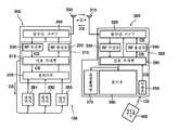
도 1은 본 발명의 무선 전송장치의 바람직한 실시형태를 도시하는 구성도로서, 도 1을 참조하여 무선 전송장치(100)에 관해서 설명한다.FIG. 1 is a configuration diagram showing a preferred embodiment of the wireless transmission device of the present invention. The
도 1의 무선 전송장치(100)는 신호 송수신장치(200)와 표시장치(300)를 구비하고 있고, 신호 송수신장치(200)는 셀렉터부(205), 제어부(210), 송수신 전환부(240), 안테나(250) 등으로 구성되어 있다.The
셀렉터부(205)는 복수의 입력단자를 가지고 있으며, 각 입력단자에는 전자기기(281, 282, 283)가 각각 접속되어 있다. 여기서, 전자기기(281, 282, 283)는 예를 들면, 각각 비디오 테이프 리코더, 광 디스크장치, 디지털 CS 튜너로서, 셀렉터부(205)에 대하여 각각 영상신호(VS) 및 음성신호(AS)(「AV(Audio Visua1)신호」)를 출력하는 것이다. 그리고, 셀렉터부(205)는 각 전자기기(281, 282, 283)로부터 출력되는 AV신호중 어느 하나의 AV신호를 선택하여 제어부(210)로 출력하는 기능을 가지고 있다.The
제어부(210)는 셀렉터부(205), 송수신 전환부(240)의 동작을 제어함과 동시에, 각 전자기기(281, 282, 283)의 동작을 후술하는 컨트롤 신호(CS)에 기초하여 각각 제어하는 기능을 가지고 있다.The
또한, 제어부(210)는 신호처리부(215), RF 송신부(220), RF 수신부(230) 등을 가지고 있다. 신호처리부(215)는 보내져 오는 영상신호(VS) 및 음성신호(AS)를 변조하여, 알맞는 진폭치로 변환된 RF신호를 생성하는 것이다. 즉, 제어부(210)는 영상신호(VS) 및 음성신호(AS)를 전파로서 송신 가능한 RF신호로 변환하는 것이다.In addition, the
RF 송신부(220)는 영상신호(VS) 및 음성신호(AS)에서 반송파를 변조하기 위한 변조기, 고주파신호로 주파수 변환하기 위한 주파수 변환기나 국부발진기, PLL회로, 송신 필터 및 전력 증폭기 등으로 구성되어 있다. 그리고, RF 송신부(220)는 신호처리부(215)로부터 보내어진 RF신호를 변조 증폭하여 출력하는 기능을 가지고 있다.The
RF 수신부(230)는 저잡음 증폭기, 수신 필터, 주파수 변환기, 국부발진기, PLL 회로 등으로 구성되어 있고, 안테나(250)에 의해 수신된 컨트롤 신호(CS)를 복조하는 기능을 가지고 있다.The
송수신 전환부(240)는 RF 송신부(220)로부터의 RF신호를 안테나(250)로 송신함과 함께, 안테나(250)에 의해 수신된 컨트롤 신호(CS)를 RF 수신부(230)로 송신하는 것이다.The transmission and
안테나(250)는 변조된 RF신호를 전파로서 송신함과 함께, 전파로서 보내져 오는 컨트롤 신호(CS)를 수신하는 기능을 가지고 있다.The
여기서, 도 1을 참조하여 신호 송수신장치(200)의 동작 예에 관해서 설명한다.Here, an operation example of the signal transmitting and receiving
우선, 셀렉터부(205)에 의해 전자기기(281, 282, 283)중 어느 하나의 전자기기(281 내지 283)로부터 영상신호(VS) 및 음성신호(AS)가 출력된다. 그리고, 이 영상신호(VS) 및 음성신호(AS)가 셀렉터부(205)를 통해서 신호처리부(215)로 보내져져 RF신호로 변환된다. 그 후, RF신호는 RF 송신부(220)에 있어서 고주파신호로 변환되어, 송수신 전환부(240)를 통해서 안테나(250)에 의해 송신된다.First, the
한편, 전파로서 송신되어 오는 컨트롤 신호(CS)가 안테나(250)에 의해 수신되고, 송수신 전환부(240)를 통해서 RF 수신부(230)에 보내어진다. 그리고, 컨트롤 신호(CS)가 RF 수신부(230)에 있어서 주파수 변환되어, 신호처리부(215)로 보내어진다. 그러면, 제어부(210)가 컨트롤 신호(CS)에 기초하여 전자기기(281, 282, 283)의 동작을 제어한다.On the other hand, the control signal CS which is transmitted as a radio wave is received by the
도 1의 신호 송수신장치(200)에 의하면, 영상신호(VS) 및 음성신호(AS)를 송신할 뿐만 아니라, 컨트롤 신호(CS)를 수신하여 이 컨트롤 신호(CS)에 기초하여 전자기기(281 내지 283)를 제어하도록 함으로써, 전자기기(281 내지 283)가 원격조작됨과 동시에, 각 전자기기(281 내지 283)의 동작이 일원화되어 관리되게 된다.According to the signal transmitting and receiving
이어서, 도 1을 참조하여 표시장치(300)에 관해서 설명한다.Next, the
도 1의 표시장치(300)는, 안테나(310), 송수신 전환부(320), 제어부(325), 표시부(360), 음성 출력부(370) 등으로 구성되어 있다. 안테나(310)는 전파(RF신호)로서 송신되어 오는 영상신호(VS) 및 음성신호(AS)를 수신함과 동시에, 컨트롤 신호(CS)를 송신하는 기능을 가지고 있다.The
송수신 전환부(320)는, 안테나(310)로부터 영상신호(VS) 및 음성신호(AS)를 수신하는 모드와, 안테나(310)로부터 컨트롤 신호(CS)를 송신하는 모드를 전환하는 것이다.The transmission /
제어부(325)는, 송수신 전환부(320)의 동작을 제어하는 기능을 가지고 있고, RF 송신부(320), RF 수신부(330) 및 신호처리부(350) 등을 가지고 있다.The
RF 수신부(330)는, 저잡음 증폭기, 수신 필터, 주파수 변환기, 국부발진기, PLL 회로 등으로 구성되어 있고, 안테나(310)에 의해 수신된 영상신호(VS) 및 음성신호(AS)를 복조하는 기능을 가지고 있다.The
RF 송신부(340)는 반송파를 컨트롤 신호(CS)에서 변조하기 위한 변조기, 고주파 신호에 주파수 변환하기 위한 주파수 변환기나 국부발진기, PLL회로, 송신 필터 및 전력 증폭기 등으로 구성되어 있다. RF 송신부(340)는 신호처리부(350)로부터 보내어진 컨트롤 신호(CS)를 변조 증폭하여 출력하는 기능을 가지고 있다.The RF transmitter 340 includes a modulator for modulating a carrier wave in a control signal CS, a frequency converter for converting a frequency into a high frequency signal, a local oscillator, a PLL circuit, a transmission filter, a power amplifier, and the like. The RF transmitter 340 has a function of modulating amplifying and outputting the control signal CS sent from the
신호처리부(350)는 영상신호(VS) 및 음성신호(AS)를 필터링 및 포맷 변환하여 표시부(360)에 대하여 출력하는 기능을 가지고 있다. 또한, 신호처리부(350)는 리모트 컨트롤부(300)로부터 보내져 오는 컨트롤 신호(CS)를 컨트롤 신호 수신부인 수광부(355)를 통하여 입력되는 것이다. 또한, 신호처리부(350)는 보내져 오는 컨트롤 신호(CS)를 변조하여, 알맞는 진폭치의 RF신호로 변환하는 기능을 가지고 있 다.The
즉, 제어부(325)는 컨트롤 신호(CS)를 전파로서 송신 가능한 RF신호로 변환함과 함께, RF신호로서 보내져 오는 영상신호(VS) 및 음성신호(AS)를 표시부(360) 및 음성 출력부(370)가 인식할 수 있도록 변환하는 기능을 가지고 있다.That is, the
표시부(360)는 예를 들어, 액정 디스플레이, 플라즈마 디스플레이 또는 TFT 디스플레이 등 박형의 표시장치이고, 영상신호(VS)에 기초하여 영상을 출력하는 기능을 가지고 있다.The
또한, 표시장치(300)의 내측 또는, 표시장치(300)의 외측에는 스피커 등으로 이루어지는 음성 출력부(370)가 마련되어 있고, 음성 출력부가 음성 소리신호(AS)에 기초하여 음성을 출력한다.In addition, an
이어서, 도 1을 참조하여 표시장치(300)의 동작 예에 관해서 설명한다.Next, an operation example of the
우선, 전파(RF신호)로서 보내어진 RF신호 영상신호(VS) 및 음성신호(AS)가 안테나(310)에 의해 수신되고, 송수신 전환부(320)를 통하여 RF 수신부(330)에 보내여진다. 그리고, RF신호는 영상신호(VS) 및 음성신호(AS)로 복조되어 신호처리부(350)로 보내어진다. 영상신호(VS) 및 음성신호(AS)는 신호처리부(350)에 의해 소정의 포맷으로 변환된 후 표시부(360)로 보내어지고, 영상신호(VS)에 기초한 영상이 출력된다.First, the RF signal video signal VS and the audio signal AS transmitted as radio waves (RF signals) are received by the
한편, 사용자에 의해 리모트 컨트롤부(400)가 조작되면, 컨트롤 신호(CS)가 수광부(355)로 보내어진다. 그러면, 컨트롤 신호(CS)는 신호처리부(350) 및 RF 송신부(340)에 있어서 RF신호로 변환된다. 그리고, RF신호로 변환된 컨트롤 신호(CS) 가 송수신 전환부(320)를 통하여 전파로서 안테나(310)로부터 외부로 송신된다.On the other hand, when the
도 1의 표시장치에 의하면, 복수의 전자기기(281 내지 283)로의 제어정보를 포함하는 컨트롤 신호(CS)가 표시장치(300)에서 수신되고, 안테나(310)로부터 송신되게 되어 전자기기의 조작을 쉽게 할 수 있다. 즉, 사용자는 리모트 컨트롤부(400)를 이용하여 표시장치(300)에 대해서만 컨트롤 신호(CS)를 송신함으로써 표시장치(300), 전자기기(281 내지 283)의 조작을 일괄되게 행할 수 있고, 사용자 인터페이스의 향상을 꾀할 수 있다.According to the display device of FIG. 1, a control signal CS including control information to the plurality of
또한, 도 1의 무선 전송장치(100)에 있어서, 신호 송수신장치(200)는 전파로서 영상신호(VS) 및 음성신호(AS)를 표시장치(300)에 대하여 송신한다. 한편, 표시장치(300)는 컨트롤 신호(CS)를 전파로서 신호 송수신장치(200)로 송신한다.In addition, in the
그리고, 신호 송수신장치(200)는 보내어진 컨트롤 신호(CS)에 기초하여 전자기기(281, 282, 283)의 동작을 제어하고, 표시장치(300)로 보내어진 영상신호(VS) 및 음성신호(AS)를 제어한다. 한편, 표시장치(300)는 보내지는 영상신호(VS) 및 음성신호(AS)에 기초하여 영상 및 음성을 출력한다.The
상기 실시형태에 의하면, 영상신호(VS) 및 음성신호(AS)와 컨트롤 신호를 신호 출력장치(200)와 표시장치(300)의 사이에서 송수신하고, 표시부(360) 및 복수의 전자기기(281, 282, 283)의 제어를 행함으로써, 사용자 인터페이스의 향상을 꾀할 수 있다. 구체적으로는 신호 송수신장치(200)에 접속되어 있는 전자기기(281, 282, 283)가 예를 들어, 표시장치(300)가 있는 방으로부터 떨어져 있고, 리모트 컨트롤부(400)로서는 직접 조작할 수 없는 경우에도, 사용자는 예를 들어, 리모트 컨트롤 부(400)에 의해, 표시장치(300)를 향하여 조작함으로써 전자기기(281, 282, 283)의 조작이 가능하게 된다.According to the above embodiment, the video signal VS, the audio signal AS, and the control signal are transmitted and received between the
또한, 신호 송수신장치(200)와 표시장치(300)로 쌍방향 통신이 가능하게 되기 때문에, 신호 송수신장치(200)에 접속되어 있는 전자기기(281, 282, 283)의 종류를 표시장치(300)로 전송할 수 있다. 따라서, 전자기기(281, 282, 283)의 선택 및 컨트롤이 예를 들어, 표시장치(300)의 메뉴 화면에 의해 일괄되게 일원화 하여 관리할 수 있기 때문에 사용자 인터페이스의 향상을 도모할 수 있다.In addition, since the two-way communication is possible between the signal transmitting and receiving
또한, 셀렉터부(205)를 신호 송수신장치(200) 내에 배치함과 함께, AV신호를 수신하는 기능을 표시장치(300)에 조립함으로써 배선 코드의 수를 적게 할 수 있어서 배선이 정연하게 된다. 또한, 예를 들면, 벽걸이 텔레비젼이나 LCD 텔레비젼 중에 AV신호를 수신하는 기능이 내장되기 때문에, 놓여지는 장소에 구애받지 않고, 미관상 깨긋하게 할 수 있다.In addition, by placing the
본 발명의 실시형태는 상기 실시형태에 한정되지 않는다.Embodiment of this invention is not limited to the said embodiment.
예를 들면, 도 1에 있어서, 셀렉터부(205)에 접속되어 있는 전자기기는 3개의 경우에 관해서 언급하고 있지만, 2개 이상의 전자기기가 접속하도록 구성되어 있는 것이다.For example, in FIG. 1, although the electronic device connected to the
또한, 도 1에 있어서, 전자기기(281, 282, 283)의 한 예로서, 비디오 테이프 리코더, 광 디스크장치 및 CS 튜너에 관해서 언급하고 있지만, 소위 MPEG 데이터 등의 소프트웨어를 재생하기 위한 장치나 전자계산기 등의 영상신호 및 음성신호를 출력하는 전자기기라면 좋다.
In addition, although Fig. 1 refers to a video tape recorder, an optical disk device, and a CS tuner as an example of the
이상 설명한 바와 같이, 사용자 인터페이스의 향상을 도모할 수 있는 표시장치, 표시 제어장치 및 무선 전송장치를 제공할 수 있다.As described above, a display device, a display control device, and a wireless transmission device capable of improving the user interface can be provided.
Claims (16)
Translated fromKoreanApplications Claiming Priority (2)
| Application Number | Priority Date | Filing Date | Title |
|---|---|---|---|
| JP?11-254787? | 1999-09-08 | ||
| JP25478799AJP2001078168A (en) | 1999-09-08 | 1999-09-08 | Display device, signal transmitter-receiver, radio transmitter and signal transmission/reception method |
Publications (2)
| Publication Number | Publication Date |
|---|---|
| KR20010030250A KR20010030250A (en) | 2001-04-16 |
| KR100730839B1true KR100730839B1 (en) | 2007-06-20 |
Family
ID=17269888
Family Applications (1)
| Application Number | Title | Priority Date | Filing Date |
|---|---|---|---|
| KR1020000051936AExpired - Fee RelatedKR100730839B1 (en) | 1999-09-08 | 2000-09-04 | The display device, signal transmitting/receiving device and radio transmitting device |
Country Status (5)
| Country | Link |
|---|---|
| US (1) | US6798459B1 (en) |
| EP (1) | EP1083744A2 (en) |
| JP (1) | JP2001078168A (en) |
| KR (1) | KR100730839B1 (en) |
| CN (1) | CN1287342A (en) |
Cited By (1)
| Publication number | Priority date | Publication date | Assignee | Title |
|---|---|---|---|---|
| KR20140136789A (en)* | 2013-05-21 | 2014-12-01 | 삼성전자주식회사 | Near field communication enabled display apparatus and method of manufacturing the same |
Families Citing this family (17)
| Publication number | Priority date | Publication date | Assignee | Title |
|---|---|---|---|---|
| JP2002064398A (en)* | 2000-08-21 | 2002-02-28 | Sony Corp | Wireless transmitter |
| JP2002111686A (en) | 2000-10-04 | 2002-04-12 | Sony Corp | Communication method and communication device |
| KR100453041B1 (en)* | 2002-02-08 | 2004-10-15 | 삼성전자주식회사 | Apparatus for transmitting and receiving a video signal, Apparatus for receiving a video signal, tranceiver therefor, and method for determining a channel |
| US6975364B2 (en)* | 2002-06-13 | 2005-12-13 | Hui-Lin Lin | Radio television and frequency modulation monitor transmitting receiving control apparatus |
| JP3957717B2 (en)* | 2003-04-30 | 2007-08-15 | 富士通株式会社 | Information processing system, information processing device, display device, and channel setting method in information processing system |
| US7685341B2 (en)* | 2005-05-06 | 2010-03-23 | Fotonation Vision Limited | Remote control apparatus for consumer electronic appliances |
| US7792970B2 (en) | 2005-06-17 | 2010-09-07 | Fotonation Vision Limited | Method for establishing a paired connection between media devices |
| KR100789554B1 (en)* | 2004-02-13 | 2007-12-28 | 샤프 가부시키가이샤 | Display apparatus, wireless transmitting/receiving system, display method, and recording medium |
| US7584494B2 (en)* | 2004-06-28 | 2009-09-01 | Dow Iii Leo F | Cable to wireless conversion system for in-home video distribution |
| DE102004055884A1 (en)* | 2004-11-19 | 2006-05-24 | Audi Ag | Lighting device for a motor vehicle comprising one or more LEDs |
| US7694048B2 (en)* | 2005-05-06 | 2010-04-06 | Fotonation Vision Limited | Remote control apparatus for printer appliances |
| JP4873978B2 (en)* | 2006-03-31 | 2012-02-08 | パナソニック株式会社 | Video supply device, video display device, and video display system including these |
| US20090115915A1 (en)* | 2006-08-09 | 2009-05-07 | Fotonation Vision Limited | Camera Based Feedback Loop Calibration of a Projection Device |
| US8482390B2 (en) | 2006-11-03 | 2013-07-09 | Nokia Corporation | Remote control of apparatus with media player |
| KR101396975B1 (en)* | 2007-07-23 | 2014-05-21 | 엘지전자 주식회사 | Remote control system and method for digital TV |
| US20100245667A1 (en)* | 2009-03-24 | 2010-09-30 | Sony Corporation | Non-standalone tv pc |
| CN109166578B (en)* | 2018-08-14 | 2021-05-11 | Oppo广东移动通信有限公司 | Mobile terminal, voice control method and related products |
Citations (2)
| Publication number | Priority date | Publication date | Assignee | Title |
|---|---|---|---|---|
| JPH10145864A (en)* | 1996-11-13 | 1998-05-29 | Nec Corp | Use limit signal transmitter/receiver for cellular radio system |
| KR19980084423A (en)* | 1997-05-23 | 1998-12-05 | 김동식 | Bidirectional remote control transceiver with automatic recognition |
Family Cites Families (12)
| Publication number | Priority date | Publication date | Assignee | Title |
|---|---|---|---|---|
| JPH03266566A (en)* | 1990-03-15 | 1991-11-27 | Alps Electric Co Ltd | Radio operation device for camera and two-direction simultaneous controller for electric apparatus |
| US5475835A (en)* | 1993-03-02 | 1995-12-12 | Research Design & Marketing Inc. | Audio-visual inventory and play-back control system |
| US5995155A (en)* | 1995-07-17 | 1999-11-30 | Gateway 2000, Inc. | Database navigation system for a home entertainment system |
| US5774063A (en)* | 1995-12-14 | 1998-06-30 | International Business Machines Corporation | Method and apparatus for software based wireless remote control of electronic devices |
| US5719622A (en)* | 1996-02-23 | 1998-02-17 | The Regents Of The University Of Michigan | Visual control selection of remote mechanisms |
| DE19629484A1 (en)* | 1996-07-12 | 1998-01-15 | Arnold & Richter Kg | Device for controlling, regulating and checking a motion picture camera |
| US6282714B1 (en)* | 1997-01-31 | 2001-08-28 | Sharewave, Inc. | Digital wireless home computer system |
| US6008777A (en) | 1997-03-07 | 1999-12-28 | Intel Corporation | Wireless connectivity between a personal computer and a television |
| US6577326B1 (en)* | 1997-08-29 | 2003-06-10 | Koninklijke Philips Electronics N.V. | Computer-controlled home theater independent user-control |
| US5982363A (en)* | 1997-10-24 | 1999-11-09 | General Instrument Corporation | Personal computer-based set-top converter for television services |
| US6034722A (en)* | 1997-11-03 | 2000-03-07 | Trimble Navigation Limited | Remote control and viewing for a total station |
| US6385772B1 (en)* | 1998-04-30 | 2002-05-07 | Texas Instruments Incorporated | Monitoring system having wireless remote viewing and control |
- 1999
- 1999-09-08JPJP25478799Apatent/JP2001078168A/ennot_activeCeased
- 2000
- 2000-09-01USUS09/653,631patent/US6798459B1/ennot_activeExpired - Fee Related
- 2000-09-04KRKR1020000051936Apatent/KR100730839B1/ennot_activeExpired - Fee Related
- 2000-09-05EPEP00307648Apatent/EP1083744A2/ennot_activeWithdrawn
- 2000-09-08CNCN00133122Apatent/CN1287342A/enactivePending
Patent Citations (2)
| Publication number | Priority date | Publication date | Assignee | Title |
|---|---|---|---|---|
| JPH10145864A (en)* | 1996-11-13 | 1998-05-29 | Nec Corp | Use limit signal transmitter/receiver for cellular radio system |
| KR19980084423A (en)* | 1997-05-23 | 1998-12-05 | 김동식 | Bidirectional remote control transceiver with automatic recognition |
Cited By (2)
| Publication number | Priority date | Publication date | Assignee | Title |
|---|---|---|---|---|
| KR20140136789A (en)* | 2013-05-21 | 2014-12-01 | 삼성전자주식회사 | Near field communication enabled display apparatus and method of manufacturing the same |
| KR102059132B1 (en)* | 2013-05-21 | 2019-12-24 | 삼성전자주식회사 | Near field communication enabled display apparatus and method of manufacturing the same |
Also Published As
| Publication number | Publication date |
|---|---|
| CN1287342A (en) | 2001-03-14 |
| KR20010030250A (en) | 2001-04-16 |
| EP1083744A2 (en) | 2001-03-14 |
| JP2001078168A (en) | 2001-03-23 |
| US6798459B1 (en) | 2004-09-28 |
Similar Documents
| Publication | Publication Date | Title |
|---|---|---|
| KR100730839B1 (en) | The display device, signal transmitting/receiving device and radio transmitting device | |
| KR100490435B1 (en) | Wireless settopbox system and method for jointing command bidirectionally | |
| US20140044277A1 (en) | Wireless audio transmission system, receiver, video camera and audio mixer | |
| JPS60187182A (en) | Remote control device used in acoustic device, etc. of system component | |
| JPH11284757A (en) | Remote control system using portable telephone | |
| US8207883B2 (en) | Portable terminal and method for remote control of electronic products | |
| JP2005229495A (en) | Control device for bathroom TV etc. | |
| KR100433240B1 (en) | Wireless two-way controlled set top system | |
| KR20030010320A (en) | Projection display system where remote control toward screen is possible | |
| JP2007013929A (en) | Remote controller for remote control, equipment operating system and remote control method for remote control | |
| JP3137819B2 (en) | Television signal processing device and television signal processing system | |
| WO2007040346A1 (en) | Multi-out broadcasting receiver system using single set-top box having plural tuners | |
| JP2002158935A (en) | Television wireless transmission system | |
| JP2001103336A (en) | Av device video image distribution system and remote control signal control method | |
| KR200142649Y1 (en) | Real imager of wireless communication method | |
| JP2006114941A (en) | Audio apparatus provided with am broadcast wave reception function | |
| KR200196900Y1 (en) | Wireless video receiver for portable video frame | |
| JP3265454B2 (en) | Tuner control system | |
| JPH11285071A (en) | Portable information terminal | |
| JPH01101085A (en) | Video information transmission system | |
| KR100336615B1 (en) | Apparatus Of Remote Controlling | |
| JPH04252551A (en) | Equipment control system | |
| KR200289678Y1 (en) | Apparatus for wireless display | |
| KR20000017565U (en) | Remote control system for a television receiver | |
| KR20000040660A (en) | Television having headphone signal transmitter |
Legal Events
| Date | Code | Title | Description |
|---|---|---|---|
| PA0109 | Patent application | St.27 status event code:A-0-1-A10-A12-nap-PA0109 | |
| PG1501 | Laying open of application | St.27 status event code:A-1-1-Q10-Q12-nap-PG1501 | |
| A201 | Request for examination | ||
| P11-X000 | Amendment of application requested | St.27 status event code:A-2-2-P10-P11-nap-X000 | |
| P13-X000 | Application amended | St.27 status event code:A-2-2-P10-P13-nap-X000 | |
| PA0201 | Request for examination | St.27 status event code:A-1-2-D10-D11-exm-PA0201 | |
| E902 | Notification of reason for refusal | ||
| PE0902 | Notice of grounds for rejection | St.27 status event code:A-1-2-D10-D21-exm-PE0902 | |
| E13-X000 | Pre-grant limitation requested | St.27 status event code:A-2-3-E10-E13-lim-X000 | |
| P11-X000 | Amendment of application requested | St.27 status event code:A-2-2-P10-P11-nap-X000 | |
| P13-X000 | Application amended | St.27 status event code:A-2-2-P10-P13-nap-X000 | |
| R18-X000 | Changes to party contact information recorded | St.27 status event code:A-3-3-R10-R18-oth-X000 | |
| E701 | Decision to grant or registration of patent right | ||
| PE0701 | Decision of registration | St.27 status event code:A-1-2-D10-D22-exm-PE0701 | |
| GRNT | Written decision to grant | ||
| PR0701 | Registration of establishment | St.27 status event code:A-2-4-F10-F11-exm-PR0701 | |
| PR1002 | Payment of registration fee | St.27 status event code:A-2-2-U10-U11-oth-PR1002 Fee payment year number:1 | |
| PG1601 | Publication of registration | St.27 status event code:A-4-4-Q10-Q13-nap-PG1601 | |
| PN2301 | Change of applicant | St.27 status event code:A-5-5-R10-R13-asn-PN2301 St.27 status event code:A-5-5-R10-R11-asn-PN2301 | |
| LAPS | Lapse due to unpaid annual fee | ||
| PC1903 | Unpaid annual fee | St.27 status event code:A-4-4-U10-U13-oth-PC1903 Not in force date:20100615 Payment event data comment text:Termination Category : DEFAULT_OF_REGISTRATION_FEE | |
| PC1903 | Unpaid annual fee | St.27 status event code:N-4-6-H10-H13-oth-PC1903 Ip right cessation event data comment text:Termination Category : DEFAULT_OF_REGISTRATION_FEE Not in force date:20100615 | |
| PN2301 | Change of applicant | St.27 status event code:A-5-5-R10-R13-asn-PN2301 St.27 status event code:A-5-5-R10-R11-asn-PN2301 |