KR100730582B1 - Iontophoresis device - Google Patents
Iontophoresis deviceDownload PDFInfo
- Publication number
- KR100730582B1 KR100730582B1KR1020060114405AKR20060114405AKR100730582B1KR 100730582 B1KR100730582 B1KR 100730582B1KR 1020060114405 AKR1020060114405 AKR 1020060114405AKR 20060114405 AKR20060114405 AKR 20060114405AKR 100730582 B1KR100730582 B1KR 100730582B1
- Authority
- KR
- South Korea
- Prior art keywords
- iontophoresis
- skin
- unit
- electrode
- electrodes
- Prior art date
- Legal status (The legal status is an assumption and is not a legal conclusion. Google has not performed a legal analysis and makes no representation as to the accuracy of the status listed.)
- Active
Links
- 238000000034methodMethods0.000claimsabstractdescription33
- 238000003745diagnosisMethods0.000claimsabstractdescription17
- 238000012546transferMethods0.000claimsabstractdescription3
- 238000012544monitoring processMethods0.000claimsdescription8
- 239000003990capacitorSubstances0.000claimsdescription6
- 239000002355dual-layerSubstances0.000claims1
- 239000002537cosmeticSubstances0.000abstractdescription10
- 230000000694effectsEffects0.000abstractdescription8
- 239000004480active ingredientSubstances0.000abstractdescription6
- 229940079593drugDrugs0.000abstractdescription6
- 239000003814drugSubstances0.000abstractdescription6
- 238000010521absorption reactionMethods0.000abstractdescription4
- 238000012876topographyMethods0.000abstract1
- 210000003491skinAnatomy0.000description60
- 238000010586diagramMethods0.000description4
- 230000005856abnormalityEffects0.000description3
- 238000005401electroluminescenceMethods0.000description3
- 238000004519manufacturing processMethods0.000description3
- 238000005259measurementMethods0.000description3
- CIWBSHSKHKDKBQ-JLAZNSOCSA-NAscorbic acidChemical compoundOC[C@H](O)[C@H]1OC(=O)C(O)=C1OCIWBSHSKHKDKBQ-JLAZNSOCSA-N0.000description2
- 210000002615epidermisAnatomy0.000description2
- 239000000126substanceSubstances0.000description2
- ZZZCUOFIHGPKAK-UHFFFAOYSA-ND-erythro-ascorbic acidNatural productsOCC1OC(=O)C(O)=C1OZZZCUOFIHGPKAK-UHFFFAOYSA-N0.000description1
- 229930003268Vitamin CNatural products0.000description1
- 239000011149active materialSubstances0.000description1
- 230000003712anti-aging effectEffects0.000description1
- 239000003963antioxidant agentSubstances0.000description1
- 230000003078antioxidant effectEffects0.000description1
- 235000006708antioxidantsNutrition0.000description1
- 230000015572biosynthetic processEffects0.000description1
- 230000004397blinkingEffects0.000description1
- 239000003086colorantSubstances0.000description1
- 239000008406cosmetic ingredientSubstances0.000description1
- 210000004207dermisAnatomy0.000description1
- 230000005684electric fieldEffects0.000description1
- 238000009499grossingMethods0.000description1
- 230000006698inductionEffects0.000description1
- 239000004973liquid crystal related substanceSubstances0.000description1
- 238000012986modificationMethods0.000description1
- 230000004048modificationEffects0.000description1
- 210000004003subcutaneous fatAnatomy0.000description1
- 239000003053toxinSubstances0.000description1
- 231100000765toxinToxicity0.000description1
- 235000019154vitamin CNutrition0.000description1
- 239000011718vitamin CSubstances0.000description1
- XLYOFNOQVPJJNP-UHFFFAOYSA-NwaterSubstancesOXLYOFNOQVPJJNP-UHFFFAOYSA-N0.000description1
- 230000002087whitening effectEffects0.000description1
- 230000037303wrinklesEffects0.000description1
- 210000000216zygomaAnatomy0.000description1
Images


Classifications
- A—HUMAN NECESSITIES
- A61—MEDICAL OR VETERINARY SCIENCE; HYGIENE
- A61N—ELECTROTHERAPY; MAGNETOTHERAPY; RADIATION THERAPY; ULTRASOUND THERAPY
- A61N1/00—Electrotherapy; Circuits therefor
- A61N1/18—Applying electric currents by contact electrodes
- A61N1/32—Applying electric currents by contact electrodes alternating or intermittent currents
- A61N1/325—Applying electric currents by contact electrodes alternating or intermittent currents for iontophoresis, i.e. transfer of media in ionic state by an electromotoric force into the body
- A—HUMAN NECESSITIES
- A61—MEDICAL OR VETERINARY SCIENCE; HYGIENE
- A61N—ELECTROTHERAPY; MAGNETOTHERAPY; RADIATION THERAPY; ULTRASOUND THERAPY
- A61N1/00—Electrotherapy; Circuits therefor
- A61N1/18—Applying electric currents by contact electrodes
- A61N1/20—Applying electric currents by contact electrodes continuous direct currents
- A61N1/30—Apparatus for iontophoresis, i.e. transfer of media in ionic state by an electromotoric force into the body, or cataphoresis
- A—HUMAN NECESSITIES
- A61—MEDICAL OR VETERINARY SCIENCE; HYGIENE
- A61N—ELECTROTHERAPY; MAGNETOTHERAPY; RADIATION THERAPY; ULTRASOUND THERAPY
- A61N1/00—Electrotherapy; Circuits therefor
- A61N1/02—Details
- A61N1/04—Electrodes
- A61N1/0404—Electrodes for external use
- A61N1/0408—Use-related aspects
- A61N1/0428—Specially adapted for iontophoresis, e.g. AC, DC or including drug reservoirs
- A61N1/0432—Anode and cathode
- A61N1/044—Shape of the electrode
- A—HUMAN NECESSITIES
- A61—MEDICAL OR VETERINARY SCIENCE; HYGIENE
- A61N—ELECTROTHERAPY; MAGNETOTHERAPY; RADIATION THERAPY; ULTRASOUND THERAPY
- A61N1/00—Electrotherapy; Circuits therefor
- A61N1/18—Applying electric currents by contact electrodes
- A61N1/32—Applying electric currents by contact electrodes alternating or intermittent currents
- A61N1/36—Applying electric currents by contact electrodes alternating or intermittent currents for stimulation
- A61N1/372—Arrangements in connection with the implantation of stimulators
- A61N1/378—Electrical supply
- A61N1/3787—Electrical supply from an external energy source
Landscapes
- Health & Medical Sciences (AREA)
- Engineering & Computer Science (AREA)
- Biomedical Technology (AREA)
- Nuclear Medicine, Radiotherapy & Molecular Imaging (AREA)
- Radiology & Medical Imaging (AREA)
- Life Sciences & Earth Sciences (AREA)
- Animal Behavior & Ethology (AREA)
- General Health & Medical Sciences (AREA)
- Public Health (AREA)
- Veterinary Medicine (AREA)
- Bioinformatics & Cheminformatics (AREA)
- Electrotherapy Devices (AREA)
Abstract
Translated fromKoreanDescription
Translated fromKorean도 1은 본 발명의 제1실시예에 따른 이온토포레시스 장치의 구성을 보여주는 블럭도.1 is a block diagram showing the configuration of an iontophoresis device according to a first embodiment of the present invention.
도 2는 본 발명에 따른 이온토포레시스 장치의 충전시 충전장치와 무선충전부 간의 구성을 보여주는 도면.2 is a view showing the configuration between the charging device and the wireless charging unit during charging of the iontophoresis device according to the present invention.
도 3은 본 발명의 제2실시예에 따른 이온토포레시스 장치의 구성을 보여주는 블록도.Figure 3 is a block diagram showing the configuration of an iontophoresis device according to a second embodiment of the present invention.
도 4는 도 3에 도시된 이온토포레시스 장치를 이용하여 이온토포레시스를 실시했을 때 전극 쌍 간에 발생하는 간섭전류의 발생방향 및 간섭파현상을 보여주는 그래프.FIG. 4 is a graph showing a generation direction and interference wave phenomenon of an interference current generated between an electrode pair when iontophoresis is performed using the iontophoresis device shown in FIG. 3.
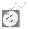
도 5는 본 발명에 따른 이온토포레시스용 칩 모듈을 마스크에 장착한 상태를 보여주는 사진.5 is a photograph showing a state in which the chip module for iontophoresis according to the present invention mounted on a mask.
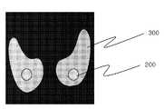
도 6은 본 발명에 따른 이온토포레시스용 칩 모듈을 패치에 장착한 상태를 보여주는 사진.Figure 6 is a photograph showing a state in which the chip module for iontophoresis according to the invention mounted on the patch.
도 7은 본 발명에 따른 이온토포레시스 장치를 이용하여 이온토포레시스를 실시하는 과정을 간략하게 보여주는 순서도.7 is a flow chart briefly showing a process of performing iontophoresis using the iontophoresis device according to the present invention.
<도면의 주요부분에 대한 부호의 설명> <Description of the symbols for the main parts of the drawings>
100 : 충전기 200 : 이온토포레시스용 칩 모듈100: charger 200: chip module for iontophoresis
202 : 하우징 210 : 무선충전부202: housing 210: wireless charging unit
212 : 전원감시부 214 : 전원공급부212: power monitoring unit 214: power supply unit
216 : 충전장치 220 : 마이크로 프로세서216: charging device 220: microprocessor
230 : 표시부 240 : 제어드라이브230: display unit 240: control drive
250 : 출력부 252 : 제1출력부250: output unit 252: first output unit
254 : 제2출력부 262 : 피부진단측정부254: second output unit 262: skin diagnostic measurement unit
264 : 출력전류감시부 270 : A/D 변환기264: output current monitoring unit 270: A / D converter
300 : 마스크 또는 패치 301, 302, 303, 304, 305, 306 : 전극300: mask or
본 발명은 이온토포레시스 장치에 관한 것으로서, 더욱 상세하게는 마스크나 패치에 탈부착할 수 있고, 이온토포레시스 시술 전에 피부 상태를 미리 진단한 다음, 피부 상태에 따라 전류량을 변화시켜 피부에 기능성 화장품이나 약품에 포함된 유효성분의 흡수시키되, 여러 쌍의 전극을 적용하여 전극 쌍 간에 발생하는 간섭전류를 이용함으로써 유효성분의 흡수를 더욱 향상시켜 피부를 개선할 수 있는 이온토포레시스 장치에 관한 것이다.The present invention relates to an iontophoresis device, and more particularly, can be attached to or detached from a mask or a patch, and the skin condition is diagnosed in advance before the iontophoresis procedure, and then the amount of current is changed according to the skin condition to provide a functional effect on the skin. Regarding the iontophoresis device, which absorbs the active ingredient contained in cosmetics or drugs, and improves the absorption of the active ingredient by applying an interference current generated between the pair of electrodes by applying a pair of electrodes to improve the skin. will be.
피부는 표피, 진피 및 피하지방조직으로 이루어져 있는데, 화장품을 피부에 바르게 되면 피부 상층의 표피는 화장품을 독소로 인지하고 분자 크기, 생체 특성 및 생화학현상 등의 영향으로 화장품의 흡수를 방해하기 때문에 피부에 실질적으로 흡수되는 화장품의 양은 매우 적다.The skin is composed of epidermis, dermis and subcutaneous fat tissue. When the cosmetic is applied to the skin, the epidermis of the upper layer of the skin perceives the cosmetic as a toxin, and it interferes with the absorption of the cosmetic due to the influence of molecular size, biometric characteristics and biochemical phenomena. The amount of cosmetics that is substantially absorbed by is very small.
이에 피부에서의 화장품이나 약물 등의 흡수를 증가시키기 위하여 이온토포레시스(iontophoresis) 방법이 개발되었다. 이온토포레시스 방법은 피부에 미세 전류를 흐르게 하여 전하를 가진 약물이나 화장품에 포함된 유효성분이 전기 반발력에 의해 피부로 침투되게 하는 방법을 일컫는다. 이러한 이온토포레시스 방법은 피부 미백 효능 물질인 비타민C를 피부에 흡수시켜 기미를 개선하거나 피부 노화방지 물질을 피부에 흡수시켜 주름살의 발생을 억제하는 데에 사용될 수 있으며, 그 효과 또한 상당한 것으로 알려져 있다.In order to increase the absorption of cosmetics and drugs in the skin, an iontophoresis method has been developed. The iontophoresis method refers to a method in which a microcurrent flows to the skin so that an active ingredient included in a drug or cosmetic with a charge penetrates into the skin by electric repulsive force. The iontophoresis method can be used to absorb vitamin C, a skin whitening substance, into the skin to improve blemishes or to absorb skin anti-aging substances into the skin and to suppress the occurrence of wrinkles. have.
현재, 시중에는 항산화와 피부보호 기능이 우수한 화장성분을 얼굴 전체에 바르고 난 뒤, 눈 밑 광대뼈부위에 미세한 전류가 흐르는 패치를 붙여 피부 주위에 전기장을 형성하도록 유도하는 방식의 이온토포레시스 장치가 판매되고 있다.Currently, the iontophoresis device is a method that induces the formation of an electric field around the skin by applying a patch of minute electric current to the cheekbones under the eyes after applying a cosmetic ingredient having excellent antioxidant and skin protection function all over the face. It is sold.
그러나 이러한 이온토포레시스 수단은 주로 일회용 마스크나 패치로 생산되고 있는데, 여기에는 전극 및 전지가 함께 내장되어 있어 생산하는데 비용이 증가하고, 전류의 세기가 정해져 있어 전류의 세기가 너무 강한 경우에는 부작용이 발생할 수 있고, 전류의 세기가 낮은 경우에는 효능을 전혀 얻을 수 없는 경우도 있다는 문제점이 있었다.However, these iontophoresis means are mainly produced as disposable masks or patches, which include electrodes and batteries embedded therein, which increase the cost of production, and the intensity of the current is determined so that side effects are too high. This may occur, and there is a problem that the efficacy may not be obtained at all when the current strength is low.
이러한 문제점을 해결하기 위하여, 대한민국 등록특허번호 제610252호에는 사용자의 피부에 부착시키는 전극과 탈부착이 가능하며, 전지가 수용되는 전지하우징과, 사용자의 피부로 투입되는 활성물질의 양을 증가시킬 수 있도록 전류의 세기 를 조절할 수 있는 전기회로가 구비된 전지유닛에 대하여 보여주고 있다.In order to solve this problem, the Republic of Korea Patent No. 610252 can be attached and detached to the electrode attached to the user's skin, the battery housing that accommodates the battery, and can increase the amount of active material introduced into the user's skin. It shows a battery unit equipped with an electric circuit that can adjust the strength of the current so that.
그러나, 이러한 전지유닛은 전극과 탈부착이 가능하여 제조비용을 절감시킬 수는 있지만, 사용자의 피부 상태에 따라 전류 세기를 조절하기 위해서는 별도의 피부 상태 진단장치를 이용하여 사용자의 피부 상태를 측정해야하는 번거로움이 있었고, 시술 중 일정한 전류가 흐르고 있는지 감시할 수 없다는 문제점이 있었다.However, although the battery unit can be attached to and detached from the electrode, the manufacturing cost can be reduced, but in order to adjust the current intensity according to the user's skin condition, it is troublesome to measure the user's skin condition using a separate skin condition diagnosis device. There was a problem, there was a problem that can not monitor whether a constant current is flowing during the procedure.
본 발명은 상기한 문제점을 해결하기 위하여 안출된 것으로서, 본 발명에서는 이온토포레시스 시술 전 사용자의 피부에 부착되는 전극을 이용하여 사용자의 피부상태를 측정하고, 측정된 사용자의 피부상태에 적합한 최적의 전류량을 발생시켜 약물이나 화장품의 유효성분이 사용자의 피부 내로 흡수되게 함으로써 사용자의 피부를 개선할 수 있는 이온토포레시스 장치를 제공하는 것을 그 목적으로 한다.The present invention has been made to solve the above problems, in the present invention is to measure the skin condition of the user using an electrode attached to the skin of the user before the iontophoresis treatment, and the optimum suitable for the measured skin condition of the user It is an object of the present invention to provide an iontophoresis device that can improve the user's skin by generating an amount of current to allow the active ingredient of the drug or cosmetic to be absorbed into the user's skin.
상기한 목적을 달성하기 위한 본 발명에 따른 이온토포레시스 장치는, 사용자의 피부에 부착되는 마스크 또는 패치에 내장되어 설치되는 다수 개의 전극과, 상기 마스크 또는 패치의 소정 위치에 탈부착 가능하도록 구성되어, 상기 전극과 전기적으로 접속되는 이온토포레시스용 칩 모듈을 포함하여 구성되는 이온토포레시스 장치에 있어서, 상기 이온토포레시스용 칩 모듈은, 무접점충전방식에 의해 전원을 충전하는 무선충전부와; 상기 무선충전부로부터 전원을 입력받아 작동하며, 제어프로그램이 저장되어 있는 마이크로 프로세서와; 상기 마이크로 프로세서의 명령에 따라 전극에 인가되는 전압, 주파수 및 전류량을 제어하는 제어드라이브와; 상 기 제어드라이브에 연결되어 상기 전극에 정전류를 전달해주는 출력부와; 상기 출력부에 연결되어 상기 전극으로부터 측정된 사용자의 생체 임피던스값을 입력받는 피부진단측정부와; 상기 피부진단측정부에서 검출된 아날로그 데이터를 디지털 데이터로 변환시켜 상기 마이크로 프로세서에 입력하는 A/D 변환기;를 포함하여 이루어지는 것을 특징으로 한다.The iontophoresis device according to the present invention for achieving the above object is configured to be detachably attached to a predetermined position of the mask or patch, and a plurality of electrodes installed in a mask or patch attached to the user's skin In the iontophoresis device comprising a chip module for iontophoresis electrically connected to the electrode, The chip module for iontophoresis, the wireless charging unit for charging the power by a contactless charging method Wow; A microprocessor operating by receiving power from the wireless charging unit and storing a control program; A control drive for controlling the amount of voltage, frequency, and current applied to the electrode according to the command of the microprocessor; An output unit connected to the control drive to transfer a constant current to the electrode; A skin diagnosis measuring unit connected to the output unit to receive a bioimpedance value of the user measured from the electrode; And an A / D converter converting analog data detected by the skin diagnosis measuring unit into digital data and inputting the same to the microprocessor.
이하, 본 발명의 바람직한 실시예를 첨부 도면에 의거하여 상세하게 설명하면 다음과 같다.Hereinafter, preferred embodiments of the present invention will be described in detail with reference to the accompanying drawings.
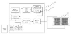
도 1은 본 발명의 제1실시예에 따른 이온토포레시스 장치의 구성을 보여주는 블럭도이고, 도 2는 본 발명에 따른 이온토포레시스 장치의 충전시 충전장치와 무선충전부 간의 구성을 보여주는 도면이다.1 is a block diagram showing the configuration of the iontophoresis device according to the first embodiment of the present invention, Figure 2 is a view showing the configuration between the charging device and the wireless charging unit during the charging of the iontophoresis device according to the present invention to be.
도 1을 참조하면, 본 발명에 따른 이온토포레시스 장치는 크게 사용자의 피부에 부착할 수 있도록 제작된 마스크나 패치(300)에 내장되어 사용자의 피부에 전류를 흘려주는 전극들(301, 302)과, 마스크나 패치(300)의 소정 부위에 탈부착할 수 있도록 구성되어 전극들(301, 302)과 전기적으로 접속되는 이온토포레시스용 칩 모듈(200)로 이루어진다.Referring to FIG. 1, the iontophoresis device according to the present invention includes electrodes 301 and 302 embedded in a mask or
이온토포레시스용 칩 모듈(200)은 하우징(202) 내부에 충전기(100)에 비접점으로 충전하기 위한 무선충전부(210)와, 무선충전부(210)에 연결되어 무선충전부(210)에 전원이 충전되는지 여부를 감시하는 전원감시부(212)와, 무선충전부(210)에 연결되어 무선충전부(210)에 충전된 전원을 각 장치들로 공급하는 전원 공급부(214)와, 전원공급부(214)로부터 전원을 공급받고 각 장치를 제어할 수 있도록 제어프로그램이 저장되어 있는 마이크로 프로세서(220)와, 마이크로 프로세서(220)의 명령에 따라 최적의 전압, 전류량 및 주파수를 발생시키는 제어드라이브(240)와, 제어드라이브(240)의 제어신호에 따라 최적의 출력값을 커넥터를 통해 연결되어 있는 전극(301, 302)으로 출력시키는 출력부(250)와, 출력부(250)에 연결되어 전극(301, 302)을 통해 측정된 사용자의 생체 임피던스, 즉 사용자의 피부 저항을 입력받는 피부진단측정부(262)와, 피부진단측정부(262)에 입력된 수치를 아날로그 데이터에서 디지털 데이터로 변환시켜 마이크로 프로세서(220)로 피드백시키는 A/D 변환기(270)를 포함하여 구성된다.The
본 발명에 따른 이온토포레시스용 칩 모듈(200)에는 출력부(250)에 연결되어 전극(301, 302)을 통해 측정된 출력전류값을 입력받는 출력전류감시부(264)가 추가로 구비될 수 있다. 출력전류감시부(264)에서는 출력부(250)를 통해 정전류가 흐르고 있는지 감시하여 오류 발생 시 마이크로 프로세서(220)를 통하여 정전류가 흐를 수 있도록 출력값을 보정하는 기능을 수행한다.The
피부진단측정부(262)는 이온토포레시스 시술 전 사용자의 피부에 부착되는 전극을 통해 생체 임피던스, 즉 피부 저항을 측정하여 사용자의 피부 내에 수분이나 유분의 함유 정도를 측정함으로써 사용자의 피부 상태에 따라 적절한 전류량을 출력할 수 있도록 한다.The skin diagnosis measuring unit 262 measures the bioimpedance, ie, skin resistance, through an electrode attached to the user's skin before the iontophoresis procedure, and then measures the degree of moisture or oil in the user's skin to determine the skin condition of the user. Therefore, the proper amount of current can be output.
마이크로 프로세서(220)에는 제어프로그램이 저장되어 있어 출력부(250)를 통해 정전류가 흐를 수 있도록 전류, 전압 및 주파수를 조절하고, 출력방법을 제어 한다. 이온토포레시스를 수행하기 전에는 출력부(250)에서 피부진단측정부(262)로 입력된 사용자의 피부 저항치를 A/D 변환기(270)를 거쳐 마이크로 프로세서(220)로 피드백시켜 사용자의 피부 상태에 적합한 전류량을 출력할 수 있도록 전류, 전압 및 주파수를 설정한다. 또한, 마이크로 프로세서(220)는 이온토포레시스를 수행하는 중에는 출력전류감시부(264)를 통해 출력부(250)를 통해 정전류가 흐르고 있는지 측정하여 측정된 전류값을 입력받아 정전류가 출력될 수 있도록 전류, 전압 및 주파수를 보정할 수도 있다The microprocessor 220 stores a control program to adjust the current, voltage and frequency so that constant current flows through the
본 발명에 따른 이온토포레시스용 칩 모듈(200)에는 온(on)/오프(off) 상태를 보여주고, 피부진단 상태를 보여주는 다양한 형태의 표시부(230)가 추가로 포함될 수 있다. 표시부(230)는 다수 개의 발광다이오드(light emitting diode : LED), 액정화면(liquid crystal display : LCD) 또는 EL(electro luminescence) 소자 등으로 구성될 수 있으며, 스스로 발광하는 LED나 EL 소자 등을 사용하는 것이 사용상태를 표시하는데 시인성을 향상시킬 수 있고 장치의 소형화를 더욱 유리하게 한다. LED를 사용하는 경우, 피부진단 상태에 따라 출력부(250)를 통해 흘려주는 전류량을 달리함으로써 이러한 상태를 여러 개의 LED를 이용하여 나타낼 수도 있고, 또는 여러 가지 색을 낼 수 있는 하나의 LED를 이용하여 나타낼 수도 있다. 또한, 온/오프 상태나 피부진단 상태 이외에도 충전시에는 충전 상태를 나타낼 수도 있으며, 사용중에는 LED를 깜빡이는 등의 방법을 이용하여 방전 정도를 나타낼 수도 있다.The
표시부(230)의 소정 위치에는 이온토포레시스용 칩 모듈(200)의 전원을 온/ 오프할 수 있는 전원스위치(미도시)가 추가로 형성될 수도 있다. 이온토포레시스용 칩 모듈(200)은 비교적 소형으로 제작되기 때문에 하나의 전원스위치를 이용하여 온/오프를 제어할 수 있도록 한다. 또한, 전원스위치를 조작하여 전원이 들어오면 마이크로 프로세서(220)에서 일련의 과정을 진행하여 이온토포레시스를 수행하고 설정된 시간이 경과되면 자동으로 전원이 차단되도록 프로그램을 설정해놓을 수도 있다.A power switch (not shown) for turning on / off the power of the
도 2는 이온토포레시스용 칩 모듈(200)을 충전기(100)에 인접시켜 비접촉 무선 충전하는 상태를 보여주고 있다. 이 방법은 무선으로 에너지를 전송하는 방법으로서, 충전기(100)를 교류 전원(AC)에 연결하면 교류가 트랜스 및 정류기를 거쳐 직류 에너지로 되고, 고주파 공진회로기를 거쳐 공진된 승압의 정현파로 변환되어 1차코일(L1)을 흐르게 되는데, 무선충전부(210) 내의 2차코일(L2)이 인접하게 되면, 1차코일(L1)과 2차코일 간에 유도전류가 발생하여 1차코일(L1)을 흐르던 전류가 2차코일(L2) 및 평활정류기를 거쳐 직류성분으로 변환되어 충전장치(216)에 충전되게 된다.FIG. 2 shows a state in which the
여기에서 충전장치(216)로는 일반적인 충전지나 콘덴서가 사용될 수 있는데, 충전지나 콘덴서를 개별적으로 사용하거나 충전지와 콘덴서를 병용할 수도 있다. 충전장치(216)에 사용되는 콘덴서는 고용량의 전기이중층(Electric Duel Layer ; EDL) 콘덴서가 사용될 수 있으며, 전기이중층 콘덴서는 일반전지에 비하여 크기가 소형이기 때문에 본 발명에 따른 이온토포레시스용 칩 모듈(200)을 소형으로 제작하는데 유리하다.Here, as the
이러한 무선충전방식은 비록 충전효율이 그리 높지는 않으나 이온토포레시스에 사용되는 소비전력이 상대적으로 그리 크지 않으므로, 짧은 시간의 충전만으로도 칩 모듈의 동작에 필요한 전력을 충분히 충전할 수 있는 한편, 비접촉방식으로 충전을 하기 때문에 칩 모듈에 별도의 접점을 형성하지 않아도 되므로 장치의 소형화를 더욱 유리하게 하고 충전이 간편하다는 이점이 있다.Although the wireless charging method does not have high charging efficiency, the power consumption used in the iontophoresis is relatively low, and thus, a short time charging can sufficiently charge the power required for the operation of the chip module, while being non-contact. Since charging is performed in such a manner, it is not necessary to form a separate contact point in the chip module, thereby making it possible to further miniaturize the device and simplify charging.
도 3은 본 발명의 제2실시예에 따른 이온토포레시스 장치의 구성을 보여주는 블록도이고, 도 4는 도 3에 도시된 이온토포레시스 장치를 이용하여 이온토포레시스를 실시했을 때 전극 쌍 간에 발생하는 간섭전류의 발생방향 및 간섭파현상을 보여주는 그래프이다.3 is a block diagram showing the configuration of the iontophoresis device according to the second embodiment of the present invention, Figure 4 is an electrode when the iontophoresis using the iontophoresis device shown in FIG. This is a graph showing the direction of interference current and the interference wave phenomenon between pairs.
도 3을 참조하면, 도 1에 도시된 이온토포레시스용 칩 모듈(200)과는 출력부의 개수와 마스크 또는 패치(300)에 형성되는 전극의 개수가 다른 것을 알 수 있다. 여기에서는 두 쌍의 전극(303, 304, 305, 306)을 사용하여 도 4에 도시된 바와 같이 제1출력부(252) 및 제2출력부(254)에 연결되는 각 전극 쌍 간에 발생하는 간섭현상을 이용함으로써 이온토포레시스 효과를 향상시키는 데에 있다.Referring to FIG. 3, it can be seen that the number of output units and the number of electrodes formed on the mask or
이렇게 두 쌍의 전극을 사용하는 경우에는 마이크로 프로세서(220)에서 출력방법을 제어하여 다양한 구동 모드로 설정할 수 있는데, 이는 제1출력부(252)와 제2출력부(254)로 출력되는 주파수, 전압값 및 전류값을 각각 같거나 다르게 설정함으로써 수행될 수 있다. 또한, 마스크 또는 패치(300)에 장착되어 있는 전극들(303, 304, 305, 306)은 제1출력부(252)나 제2출력부(254) 중 어디에 연결하여도 상관없다.When two pairs of electrodes are used as described above, the microprocessor 220 may control the output method and set various driving modes, such as the frequency output to the first output unit 252 and the
도 1과 도 3에서는 각각 한 쌍과 두 쌍의 전극을 사용한 경우에 대하여 설명하였으나, 시술 부위나 목적에 따라서 전극의 개수는 변동이 가능하다.1 and 3 illustrate a case where a pair and two pairs of electrodes are used, respectively, but the number of electrodes may vary according to the treatment site or purpose.
도 5는 본 발명에 따른 이온토포레시스용 칩 모듈을 마스크에 장착한 상태를 보여주는 사진이고, 도 6은 본 발명에 따른 이온토포레시스용 칩 모듈을 패치에 장착한 상태를 보여주는 사진이다.5 is a photograph showing a state in which a chip module for iontophoresis according to the present invention mounted on a mask, and FIG. 6 is a photograph showing a state in which a chip module for iontophoresis according to the present invention is mounted on a patch.
도 5 및 도 6을 참조하면, 도 1 또는 도 3에 도시된 바와 같은 구성을 갖는 이온토포레시스용 칩 모듈(200)을 마스크 또는 패치(300)에 장착한 상태를 보여주고 있으며, 이온토포레시스용 칩 모듈(200)과 마스크 또는 패치(300) 간에는 별도의 커넥터가 설치되어 있어 이온토포레시스용 칩 모듈(200)의 출력부로부터 출력되는 전류가 마스크 또는 패치(300) 내부에 장착되어 있는 전극으로 흐를 수 있도록 되어 있다.5 and 6, the
이온토포레시스용 칩 모듈(200)은 화장품이나 약물의 이온성분에 따라 또는 용도에 따라 개별로 구성하여 이온성분 또는 용도에 맞게 선택하여 사용할 수도 있다.The
또한, 본 발명에 따른 이온토포레시스용 칩 모듈(200)은 모든 구성요소들을 하나의 칩 상에 집적하여 구성함으로써 이온토포레시스용 칩 모듈(200)의 생산을 단순하게 할 수도 있다.In addition, the
이하에서는 본 발명에 따른 이온토포레시스 방법에 대하여 설명한다.Hereinafter, the iontophoresis method according to the present invention will be described.
도 7은 본 발명에 따른 이온토포레시스 장치를 이용하여 이온토포레시스를 실시하는 과정을 간략하게 보여주는 순서도이다.7 is a flowchart briefly illustrating a process of performing iontophoresis using the iontophoresis device according to the present invention.
먼저, 사용자는 마스크 또는 패치(300)에 이온토포레시스용 칩 모듈(200)을 장착하고, 마스크 또는 패치(300)를 얼굴이나 피부에 부착시킨다.First, the user mounts the
그런 후에 이온토포레시스용 칩 모듈(200)에 설치되어 있는 전원 스위치(미도시)를 조작하여 전원을 켠다.After that, the power is turned on by operating a power switch (not shown) installed in the
이온토포레시스용 칩 모듈(200)에 전원이 들어오면, 마이크로 프로세서(220)에 미리 저장되어 있는 프로그램에 따라 사용자의 생체 임피던스, 즉 피부 저항을 측정하여 피부상태를 진단한다. 이는 사용자의 피부에 약한 전류를 흘려주어 체내의 저항값을 측정하는 것으로서, 체내의 수분 양에 따라 저항값이 달라질 수 있다. 예를 들어 피부에 수분이 많으면 전류가 흐르는 통로가 넓어져 저항치가 적게 나오고, 피부에 수분이 적으면 전류가 흐르는 통로가 좁아져 저항이 크게 되므로 이를 통해 피부 내에 함유되어 있는 수분 양을 알아낼 수 있다.When power is supplied to the
이렇게 측정된 사용자의 피부 저항값은 마스크 또는 패치(300) 내에 내장되어 있는 전극을 통해 측정되며, 이는 출력부(250)를 통해 피부진단측정부(262)를 거쳐 A/D 변환기(270)에서 디지털 데이터로 변환되어 마이크로 프로세서(220)에 전달된다.The skin resistance value measured in this way is measured by an electrode embedded in the mask or
마이크로 프로세서(220)에서는 피부진단측정부(262)로부터 전달된 피부 저항치를 이용하여 사용자의 피부상태에 적합한 최적의 전압, 전류 및 주파수를 설정하 여 제어드라이브(240)에 전달하면, 제어드라이브(240)에서는 최적의 전압, 전류 및 주파수를 갖는 출력값을 출력부(250)를 통해 출력시키고, 출력부(250)에 연결되어 있는 전극(301, 302)을 통해 정전류를 흘려 이온토포레시스 시술을 수행한다. 이때, 두 쌍의 전극을 사용하는 경우 각 출력부에 연결되는 전극 쌍 간에 간섭전류가 발생하여 이온토포레시스 효과를 더욱 향상시킬 수 있다.The microprocessor 220 sets the optimum voltage, current, and frequency suitable for the skin condition of the user by using the skin resistance transmitted from the skin diagnosis measuring unit 262 and transmits the control voltage to the
이온토포레시스 시술을 수행하면서 전극(301, 302)을 통해 정전류가 흐르고 있는지 측정하여 출력부(250)를 통해 출력전류감시부(264)로 측정치를 전달하고, 출력전류감시부(264)에 전달된 측정치를 A/D 변환기(270)로 전달하여 아날로그 데이터에서 디지털 데이터로 변환시켜 마이크로 프로세서(220)로 전달하면, 마이크로 프로세서(220)에서는 이상 유무를 감지하여 이상이 감지되면 출력부(250)에서 정전류가 흐르도록 전압, 전류 및 주파수를 보정한다.While performing the iontophoresis procedure, it is measured whether the constant current is flowing through the electrodes 301 and 302, and transmits the measurement value to the output current monitor 264 through the
프로그래밍된 이온토포레시스 시술이 완료되면, 마이크로 프로세서(220)에서는 전원을 차단하도록 전원공급부(214)에 명령을 내린다.Upon completion of the programmed iontophoresis procedure, the microprocessor 220 commands the
이온토포레시스용 칩 모듈(200)의 전원이 꺼지면, 사용자는 마스크 또는 패치(300)에서 이온토포레시스용 칩 모듈(200)을 분리하고, 이온토포레시스용 칩 모듈(200)을 충전기(100)에 인접시켜 다시 재충전시킨다.When the power of the
이와 같이, 본 발명의 상세한 설명에서는 구체적인 실시예에 관해 설명하였으나, 본 발명의 범주에서 벗어나지 않는 한도 내에서 여러 가지 변형이 가능함은 물론이다. 그러므로, 본 발명의 범위는 설명된 실시예에 국한되어 정해져서는 안되 며, 후술하는 특허청구범위뿐만 아니라 이 청구범위와 균등한 것들에 의해 정해져야 한다.As described above, in the detailed description of the present invention, specific embodiments have been described, but various modifications are possible without departing from the scope of the present invention. Therefore, the scope of the present invention should not be limited to the described embodiments, but should be defined by the claims below and equivalents thereof.
이상에서 상술한 바와 같이 본 발명에 따른 이온토포레시스 장치는, 사용자의 피부 상태를 미리 진단한 후 진단된 사용자의 피부 상태에 알맞은 최적의 전류량을 이용하여 이온토포레시스를 실시함으로써 사용자의 피부를 개선할 수 있는 효과가 있다.As described above, the iontophoresis device according to the present invention diagnoses the skin condition of the user in advance, and then performs iontophoresis using an optimal amount of current suitable for the diagnosed skin condition of the user. There is an effect to improve.
또한, 본 발명은 두 쌍의 전극을 이용하여 각 전극 쌍 간에 발생하는 간섭현상을 통해 이온토포레시스 효과를 더욱 향상시켜 사용자의 피부를 개선할 수 있는 효과도 있다.In addition, the present invention also has the effect of improving the skin of the user by further improving the iontophoresis effect through the interference phenomenon generated between each pair of electrodes using two pairs of electrodes.
Claims (10)
Translated fromKoreanPriority Applications (6)
| Application Number | Priority Date | Filing Date | Title |
|---|---|---|---|
| KR1020060114405AKR100730582B1 (en) | 2006-11-20 | 2006-11-20 | Iontophoresis device |
| CN2007800429918ACN101541373B (en) | 2006-11-20 | 2007-09-07 | Equipment for iontophoresis |
| EP07808131AEP2089103B1 (en) | 2006-11-20 | 2007-09-07 | An apparatus for iontophoresis |
| JP2009538302AJP5254243B2 (en) | 2006-11-20 | 2007-09-07 | Iontophoresis device |
| PCT/KR2007/004338WO2008062943A1 (en) | 2006-11-20 | 2007-09-07 | An apparatus for iontophoresis |
| US12/515,269US8204587B2 (en) | 2006-11-20 | 2007-09-07 | Apparatus for iontophoresis |
Applications Claiming Priority (1)
| Application Number | Priority Date | Filing Date | Title |
|---|---|---|---|
| KR1020060114405AKR100730582B1 (en) | 2006-11-20 | 2006-11-20 | Iontophoresis device |
Publications (1)
| Publication Number | Publication Date |
|---|---|
| KR100730582B1true KR100730582B1 (en) | 2007-06-20 |
Family
ID=38372927
Family Applications (1)
| Application Number | Title | Priority Date | Filing Date |
|---|---|---|---|
| KR1020060114405AActiveKR100730582B1 (en) | 2006-11-20 | 2006-11-20 | Iontophoresis device |
Country Status (6)
| Country | Link |
|---|---|
| US (1) | US8204587B2 (en) |
| EP (1) | EP2089103B1 (en) |
| JP (1) | JP5254243B2 (en) |
| KR (1) | KR100730582B1 (en) |
| CN (1) | CN101541373B (en) |
| WO (1) | WO2008062943A1 (en) |
Cited By (9)
| Publication number | Priority date | Publication date | Assignee | Title |
|---|---|---|---|---|
| KR101533403B1 (en)* | 2012-11-06 | 2015-07-03 | 한국과학기술원 | Iontophoresis patch |
| WO2015167037A1 (en)* | 2014-04-29 | 2015-11-05 | 주식회사 케이헬쓰웨어 | Iontophoresis injection device and injection method |
| KR20160001579U (en)* | 2014-11-03 | 2016-05-13 | (주)아모레퍼시픽 | Mask pack attached needle patch operated with wireless electric |
| KR101776473B1 (en)* | 2016-03-21 | 2017-09-19 | 박은홍 | Method for iontophoresis using iontophoresis apparatus for mask pack |
| KR20180047088A (en)* | 2016-10-31 | 2018-05-10 | 인천대학교 산학협력단 | Apparatus for measuring skin condition, method and computer program for providing skin condition information using thereof |
| KR20210006574A (en) | 2019-07-09 | 2021-01-19 | 오경진 | Disposable drug delivery patch detachable iontophoresis device |
| KR20210035710A (en)* | 2019-09-24 | 2021-04-01 | 단국대학교 천안캠퍼스 산학협력단 | Personalized mask device using electrical stimulation |
| KR20210035713A (en)* | 2019-09-24 | 2021-04-01 | 단국대학교 천안캠퍼스 산학협력단 | Personalized fat reduction device using electrical stimulation |
| KR102447720B1 (en) | 2021-06-25 | 2022-09-29 | 엘지전자 주식회사 | beauty equipment |
Families Citing this family (17)
| Publication number | Priority date | Publication date | Assignee | Title |
|---|---|---|---|---|
| WO2012090756A1 (en)* | 2010-12-28 | 2012-07-05 | テルモ株式会社 | Transdermal drug administration device |
| US10201703B2 (en)* | 2012-02-02 | 2019-02-12 | The United States Of America, As Represented By The Department Of Veterans Affairs | Integrated surface stimulation device for wound therapy and infection control |
| EP2949359A4 (en)* | 2013-01-23 | 2016-09-14 | Terumo Corp | Drug administration device, and control method |
| JP6038194B2 (en)* | 2013-02-18 | 2016-12-07 | テルモ株式会社 | Drug administration device, drug administration system, and operation method thereof |
| GB201415611D0 (en)* | 2014-09-03 | 2014-10-15 | Univ Strathclyde | Apparatus for topical application of material |
| FR3048363A1 (en)* | 2016-03-04 | 2017-09-08 | Oreal | COSMETIC ELECTRICAL ARTICLE WITH REPOSITIONABLE BATTERY |
| JP2019517354A (en)* | 2016-06-08 | 2019-06-24 | アモセンス・カンパニー・リミテッドAmosense Co., Ltd. | Iontophoresis device, iontophoresis method and skin cosmetic device including the same |
| GB2554455A (en)* | 2016-09-29 | 2018-04-04 | Feeligreen Sa | Skin treatment device and method for delivery of an active ingredient into the human skin by means of iontophoresis, using an array of electrodes |
| CN106512205B (en)* | 2016-11-03 | 2019-02-05 | 杭州益贴康智能科技有限公司 | A kind of facial mask control device and its application method with sleeping cosmetology function |
| US11458309B2 (en) | 2017-09-19 | 2022-10-04 | United States Government As Represented By The Department Of Veterans Affairs | Flexible implantable tissue stimulator and methods of making and using same |
| US11124901B2 (en) | 2017-11-27 | 2021-09-21 | First Step Holdings, Llc | Composite fabric, method for forming composite fabric, and use of a composite matter fabric |
| KR20190116749A (en) | 2018-04-05 | 2019-10-15 | 삼성전자주식회사 | Method for performing wireless communication using biometric sensor and electronic device therefor |
| CN108853720A (en)* | 2018-05-16 | 2018-11-23 | 邱骅轩 | A kind of adaptive transdermal iontophoretic method import system for beauty treatment fields |
| US10279176B1 (en) | 2018-06-11 | 2019-05-07 | First Step Holdings, Llc | Method and apparatus for increasing absorption of medications and cosmeceuticals through the skin of the user |
| CN109364373B (en)* | 2018-12-24 | 2022-11-11 | 李新虹 | Facial paralysis recovery nursing device based on penetration therapy |
| KR102357602B1 (en)* | 2020-10-13 | 2022-02-07 | (주) 레지에나 | Sheet mask device |
| KR102715110B1 (en)* | 2021-07-22 | 2024-10-11 | (주) 레지에나 | Sheet mask device |
Citations (5)
| Publication number | Priority date | Publication date | Assignee | Title |
|---|---|---|---|---|
| KR19980701451A (en)* | 1995-01-18 | 1998-05-15 | 스티븐 에프. 스톤 | Electrotransport Device Having Reusable Controller Power Saver |
| KR19980702570A (en)* | 1995-03-24 | 1998-07-15 | 스톤 스티븐 에프 | Electronic feeder and its display method |
| KR19990022342A (en)* | 1995-06-05 | 1999-03-25 | 스톤 스티븐 에프. | Device for Percutaneous Electrotransport Administration of Fentanyl and Serfentanil |
| JP2001095928A (en) | 1999-08-25 | 2001-04-10 | Becton Dickinson & Co | Drug injection device by iontophoresis |
| KR20010070084A (en)* | 1999-09-20 | 2001-07-25 | 나까도미 히로다카 | Iontophoresis system |
Family Cites Families (27)
| Publication number | Priority date | Publication date | Assignee | Title |
|---|---|---|---|---|
| CA1262564A (en)* | 1983-09-01 | 1989-10-31 | Minoru Sasaki | Iontophoresis device |
| US5042975A (en)* | 1986-07-25 | 1991-08-27 | Rutgers, The State University Of New Jersey | Iontotherapeutic device and process and iontotherapeutic unit dose |
| JPH0345271A (en)* | 1989-07-12 | 1991-02-26 | Teijin Ltd | Ion phoresis device |
| US5047007A (en)* | 1989-12-22 | 1991-09-10 | Medtronic, Inc. | Method and apparatus for pulsed iontophoretic drug delivery |
| US5254081A (en)* | 1991-02-01 | 1993-10-19 | Empi, Inc. | Multiple site drug iontophoresis electronic device and method |
| US5450845A (en)* | 1993-01-11 | 1995-09-19 | Axelgaard; Jens | Medical electrode system |
| DE69633733T2 (en)* | 1995-08-31 | 2006-02-02 | Hisamitsu Pharmaceutical Co., Inc., Tosu | IONTOPHORETIC DEVICE AND CORRESPONDING METHOD FOR CONTROLLING THE ELECTRICITY |
| RU2090613C1 (en) | 1995-09-01 | 1997-09-20 | Каньчжэн Юрий Владимирович Цзян | Device for communication of natural information supply to biological object |
| US5688232A (en)* | 1995-09-28 | 1997-11-18 | Becton Dickinson And Company | Iontophoretic drug delivery device having an improved controller |
| US5926642A (en) | 1995-10-06 | 1999-07-20 | Advanced Micro Devices, Inc. | RISC86 instruction set |
| US6319241B1 (en)* | 1998-04-30 | 2001-11-20 | Medtronic, Inc. | Techniques for positioning therapy delivery elements within a spinal cord or a brain |
| US6148232A (en)* | 1998-11-09 | 2000-11-14 | Elecsys Ltd. | Transdermal drug delivery and analyte extraction |
| US6597946B2 (en)* | 1998-11-09 | 2003-07-22 | Transpharma Ltd. | Electronic card for transdermal drug delivery and analyte extraction |
| US6119038A (en)* | 1998-11-20 | 2000-09-12 | Proventure, Llc | Handheld skin treatment system and method |
| KR20010002513A (en) | 1999-06-15 | 2001-01-15 | 김영환 | Method for displaying location of base station in base station manager |
| EP1292359A4 (en)* | 2000-05-22 | 2005-03-30 | Merck & Co Inc | System and method for assessing the performance of a pharmaceutical agent delivery system |
| AU2002211629A1 (en)* | 2000-10-10 | 2002-04-22 | Microchips, Inc. | Microchip reservoir devices using wireless transmission of power and data |
| US6823202B2 (en)* | 2002-04-01 | 2004-11-23 | Iomed, Inc. | Iontophoretic power supply |
| US7630759B2 (en)* | 2002-05-20 | 2009-12-08 | Epi-Sci, Llc | Method and system for detecting electrophysiological changes in pre-cancerous and cancerous breast tissue and epithelium |
| KR100965239B1 (en)* | 2003-08-20 | 2010-06-22 | 삼성에스디아이 주식회사 | Light emitting block using solar cell |
| KR100522927B1 (en)* | 2004-03-03 | 2005-10-19 | 주식회사 프라임 메디텍 | Ion Mask |
| KR100610252B1 (en) | 2004-07-01 | 2006-08-10 | 주식회사 엘지생활건강 | Iontophoresis device |
| KR100610253B1 (en)* | 2004-10-12 | 2006-08-09 | 주식회사 엘지생활건강 | Iontophoresis device |
| JPWO2007037476A1 (en)* | 2005-09-30 | 2009-04-16 | Tti・エルビュー株式会社 | Iontophoresis device for controlling the dosage and timing of sleep inducers and stimulants |
| EP3165247B1 (en)* | 2006-02-09 | 2020-10-28 | DEKA Products Limited Partnership | Pumping fluid delivery systems and methods using force application assembley |
| US7945320B2 (en)* | 2007-08-17 | 2011-05-17 | Isis Biopolymer, Inc. | Iontophoretic drug delivery system |
| EP2242537A1 (en)* | 2007-12-10 | 2010-10-27 | Isis Biopolymer LLC | Iontophoretic drug delivery device and software application |
- 2006
- 2006-11-20KRKR1020060114405Apatent/KR100730582B1/enactiveActive
- 2007
- 2007-09-07JPJP2009538302Apatent/JP5254243B2/ennot_activeExpired - Fee Related
- 2007-09-07CNCN2007800429918Apatent/CN101541373B/ennot_activeExpired - Fee Related
- 2007-09-07WOPCT/KR2007/004338patent/WO2008062943A1/enactiveApplication Filing
- 2007-09-07USUS12/515,269patent/US8204587B2/ennot_activeExpired - Fee Related
- 2007-09-07EPEP07808131Apatent/EP2089103B1/ennot_activeNot-in-force
Patent Citations (5)
| Publication number | Priority date | Publication date | Assignee | Title |
|---|---|---|---|---|
| KR19980701451A (en)* | 1995-01-18 | 1998-05-15 | 스티븐 에프. 스톤 | Electrotransport Device Having Reusable Controller Power Saver |
| KR19980702570A (en)* | 1995-03-24 | 1998-07-15 | 스톤 스티븐 에프 | Electronic feeder and its display method |
| KR19990022342A (en)* | 1995-06-05 | 1999-03-25 | 스톤 스티븐 에프. | Device for Percutaneous Electrotransport Administration of Fentanyl and Serfentanil |
| JP2001095928A (en) | 1999-08-25 | 2001-04-10 | Becton Dickinson & Co | Drug injection device by iontophoresis |
| KR20010070084A (en)* | 1999-09-20 | 2001-07-25 | 나까도미 히로다카 | Iontophoresis system |
Cited By (13)
| Publication number | Priority date | Publication date | Assignee | Title |
|---|---|---|---|---|
| KR101533403B1 (en)* | 2012-11-06 | 2015-07-03 | 한국과학기술원 | Iontophoresis patch |
| WO2015167037A1 (en)* | 2014-04-29 | 2015-11-05 | 주식회사 케이헬쓰웨어 | Iontophoresis injection device and injection method |
| KR20160001579U (en)* | 2014-11-03 | 2016-05-13 | (주)아모레퍼시픽 | Mask pack attached needle patch operated with wireless electric |
| KR200483166Y1 (en)* | 2014-11-03 | 2017-04-21 | (주)아모레퍼시픽 | Mask pack attached needle patch operated with wireless electric |
| KR101776473B1 (en)* | 2016-03-21 | 2017-09-19 | 박은홍 | Method for iontophoresis using iontophoresis apparatus for mask pack |
| KR20180047088A (en)* | 2016-10-31 | 2018-05-10 | 인천대학교 산학협력단 | Apparatus for measuring skin condition, method and computer program for providing skin condition information using thereof |
| KR101892816B1 (en)* | 2016-10-31 | 2018-08-28 | 인천대학교 산학협력단 | Apparatus for measuring skin condition, method and computer program for providing skin condition information using thereof |
| KR20210006574A (en) | 2019-07-09 | 2021-01-19 | 오경진 | Disposable drug delivery patch detachable iontophoresis device |
| KR20210035710A (en)* | 2019-09-24 | 2021-04-01 | 단국대학교 천안캠퍼스 산학협력단 | Personalized mask device using electrical stimulation |
| KR20210035713A (en)* | 2019-09-24 | 2021-04-01 | 단국대학교 천안캠퍼스 산학협력단 | Personalized fat reduction device using electrical stimulation |
| KR102285205B1 (en)* | 2019-09-24 | 2021-08-04 | 단국대학교 천안캠퍼스 산학협력단 | Personalized fat reduction device using electrical stimulation |
| KR102285202B1 (en)* | 2019-09-24 | 2021-08-04 | 단국대학교 천안캠퍼스 산학협력단 | Personalized mask device using electrical stimulation |
| KR102447720B1 (en) | 2021-06-25 | 2022-09-29 | 엘지전자 주식회사 | beauty equipment |
Also Published As
| Publication number | Publication date |
|---|---|
| WO2008062943A1 (en) | 2008-05-29 |
| EP2089103A1 (en) | 2009-08-19 |
| CN101541373A (en) | 2009-09-23 |
| EP2089103A4 (en) | 2010-09-29 |
| CN101541373B (en) | 2012-12-05 |
| US20100241057A1 (en) | 2010-09-23 |
| US8204587B2 (en) | 2012-06-19 |
| JP2010510023A (en) | 2010-04-02 |
| JP5254243B2 (en) | 2013-08-07 |
| EP2089103B1 (en) | 2012-12-05 |
Similar Documents
| Publication | Publication Date | Title |
|---|---|---|
| KR100730582B1 (en) | Iontophoresis device | |
| CN214074721U (en) | Temperature-controlled radio frequency beauty device | |
| US8731657B1 (en) | Multi-mode microcurrent stimulus system with safety circuitry and related methods | |
| KR102008869B1 (en) | Portable high intensity focused ultrasonic skin care device | |
| JP6076368B2 (en) | Skin treatment equipment | |
| KR101997045B1 (en) | Sterilizable skin care device for wrinkle care | |
| CN107847756B (en) | Skin care device | |
| KR101649603B1 (en) | Apparatus for beauty care using high radio frequency with cross-linked electrodes | |
| BRPI0713151A2 (en) | noninvasive neurostimulatory system | |
| US20170095660A1 (en) | Iontophoresis injection device and injection method | |
| CN111544769B (en) | A low power consumption neuromuscular stimulator | |
| KR20170027263A (en) | System of complexing Ultrasonic Wave and Micro-current for performing Skin Care | |
| CN112234830B (en) | EMS and RF function switching circuit and massager | |
| KR20110018021A (en) | Heterogeneous light irradiation portable skin treatment device | |
| KR101220541B1 (en) | Device for medical skin care | |
| CN219700828U (en) | Percutaneous electricity, near infrared ray soft tissue injury physiotherapy electrode and physiotherapy device | |
| KR100992931B1 (en) | Body core measurement diagnosis device and medical diathermy connected thereto | |
| US9889296B2 (en) | Signal adjustment for electrotherapy | |
| KR102341817B1 (en) | Method of drive control for smart skin care device | |
| US12357528B2 (en) | Multi-functional portable skin care device | |
| KR102056014B1 (en) | The cartrige for high intensity focused ultrasonic skin care device | |
| CN219149005U (en) | Electronic equipment | |
| KR20190062643A (en) | Glasses type apparatus for skim care | |
| KR102341818B1 (en) | Smart skin care device | |
| KR20080090182A (en) | Low Frequency Thermal Therapy Equipment |
Legal Events
| Date | Code | Title | Description |
|---|---|---|---|
| A201 | Request for examination | ||
| PA0109 | Patent application | Patent event code:PA01091R01D Comment text:Patent Application Patent event date:20061120 | |
| PA0201 | Request for examination | ||
| A302 | Request for accelerated examination | ||
| PA0302 | Request for accelerated examination | Patent event date:20070419 Patent event code:PA03022R01D Comment text:Request for Accelerated Examination Patent event date:20061120 Patent event code:PA03021R01I Comment text:Patent Application | |
| E701 | Decision to grant or registration of patent right | ||
| PE0701 | Decision of registration | Patent event code:PE07011S01D Comment text:Decision to Grant Registration Patent event date:20070531 | |
| GRNT | Written decision to grant | ||
| PR0701 | Registration of establishment | Comment text:Registration of Establishment Patent event date:20070614 Patent event code:PR07011E01D | |
| PR1002 | Payment of registration fee | Payment date:20070615 End annual number:3 Start annual number:1 | |
| PG1601 | Publication of registration | ||
| PR1001 | Payment of annual fee | Payment date:20100615 Start annual number:4 End annual number:4 | |
| PR1001 | Payment of annual fee | Payment date:20110614 Start annual number:5 End annual number:5 | |
| PR1001 | Payment of annual fee | Payment date:20120612 Start annual number:6 End annual number:6 | |
| FPAY | Annual fee payment | Payment date:20130612 Year of fee payment:7 | |
| PR1001 | Payment of annual fee | Payment date:20130612 Start annual number:7 End annual number:7 | |
| FPAY | Annual fee payment | Payment date:20140610 Year of fee payment:8 | |
| PR1001 | Payment of annual fee | Payment date:20140610 Start annual number:8 End annual number:8 | |
| FPAY | Annual fee payment | Payment date:20150610 Year of fee payment:9 | |
| PR1001 | Payment of annual fee | Payment date:20150610 Start annual number:9 End annual number:9 | |
| FPAY | Annual fee payment | Payment date:20160630 Year of fee payment:10 | |
| PR1001 | Payment of annual fee | Payment date:20160630 Start annual number:10 End annual number:10 | |
| FPAY | Annual fee payment | Payment date:20170612 Year of fee payment:11 | |
| PR1001 | Payment of annual fee | Payment date:20170612 Start annual number:11 End annual number:11 | |
| FPAY | Annual fee payment | Payment date:20180528 Year of fee payment:12 | |
| PR1001 | Payment of annual fee | Payment date:20180528 Start annual number:12 End annual number:12 | |
| FPAY | Annual fee payment | Payment date:20190326 Year of fee payment:13 | |
| PR1001 | Payment of annual fee | Payment date:20190326 Start annual number:13 End annual number:13 | |
| PR1001 | Payment of annual fee | Payment date:20200601 Start annual number:14 End annual number:14 | |
| PR1001 | Payment of annual fee | Payment date:20210331 Start annual number:15 End annual number:15 | |
| PR1001 | Payment of annual fee | Payment date:20220321 Start annual number:16 End annual number:16 | |
| PR1001 | Payment of annual fee | Payment date:20230321 Start annual number:17 End annual number:17 | |
| PR1001 | Payment of annual fee | Payment date:20240620 Start annual number:18 End annual number:18 |