KR100728507B1 - System and method for adjusting antenna radiation in a wireless network - Google Patents
System and method for adjusting antenna radiation in a wireless networkDownload PDFInfo
- Publication number
- KR100728507B1 KR100728507B1KR1020000006434AKR20000006434AKR100728507B1KR 100728507 B1KR100728507 B1KR 100728507B1KR 1020000006434 AKR1020000006434 AKR 1020000006434AKR 20000006434 AKR20000006434 AKR 20000006434AKR 100728507 B1KR100728507 B1KR 100728507B1
- Authority
- KR
- South Korea
- Prior art keywords
- antenna
- antenna radiation
- delete delete
- measurement
- radiation
- Prior art date
- Legal status (The legal status is an assumption and is not a legal conclusion. Google has not performed a legal analysis and makes no representation as to the accuracy of the status listed.)
- Expired - Fee Related
Links
Images


Classifications
- H—ELECTRICITY
- H04—ELECTRIC COMMUNICATION TECHNIQUE
- H04W—WIRELESS COMMUNICATION NETWORKS
- H04W16/00—Network planning, e.g. coverage or traffic planning tools; Network deployment, e.g. resource partitioning or cells structures
- H04W16/24—Cell structures
- H04W16/28—Cell structures using beam steering
- H—ELECTRICITY
- H01—ELECTRIC ELEMENTS
- H01Q—ANTENNAS, i.e. RADIO AERIALS
- H01Q1/00—Details of, or arrangements associated with, antennas
- H01Q1/12—Supports; Mounting means
- H01Q1/22—Supports; Mounting means by structural association with other equipment or articles
- H01Q1/24—Supports; Mounting means by structural association with other equipment or articles with receiving set
- H01Q1/241—Supports; Mounting means by structural association with other equipment or articles with receiving set used in mobile communications, e.g. GSM
- H01Q1/246—Supports; Mounting means by structural association with other equipment or articles with receiving set used in mobile communications, e.g. GSM specially adapted for base stations
- H—ELECTRICITY
- H01—ELECTRIC ELEMENTS
- H01Q—ANTENNAS, i.e. RADIO AERIALS
- H01Q3/00—Arrangements for changing or varying the orientation or the shape of the directional pattern of the waves radiated from an antenna or antenna system
- H01Q3/26—Arrangements for changing or varying the orientation or the shape of the directional pattern of the waves radiated from an antenna or antenna system varying the relative phase or relative amplitude of energisation between two or more active radiating elements; varying the distribution of energy across a radiating aperture
- H01Q3/2605—Array of radiating elements provided with a feedback control over the element weights, e.g. adaptive arrays
Landscapes
- Engineering & Computer Science (AREA)
- Computer Networks & Wireless Communication (AREA)
- Signal Processing (AREA)
- Mobile Radio Communication Systems (AREA)
- Variable-Direction Aerials And Aerial Arrays (AREA)
- Radio Transmission System (AREA)
Abstract
Translated fromKoreanDescription
Translated fromKorean도 1은 본 발명에 따른 무선 네트워크의 제 1 실시예에 대한 블록도.1 is a block diagram of a first embodiment of a wireless network in accordance with the present invention;
도 2는 본 발명에 따라 무선 네트워크에서 안테나 복사를 조정하는 방법을 설명하는 흐름도.2 is a flow chart illustrating a method of adjusting antenna radiation in a wireless network in accordance with the present invention.
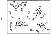
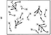
도 3a 내지 도 3c는 본 발명에 따른 잠재적이고 결과적인 안테나 복사 방향들의 그래픽적인 도면들.3A-3C are graphical views of potential and resulting antenna radiation directions in accordance with the present invention.
도 4는 본 발명에 따른 측정 과정을 도시하는 블록도.4 is a block diagram illustrating a measurement process according to the invention.
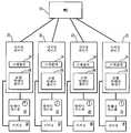
도 5는 본 발명에 따라 신호-대-간섭비를 측정하는 위치 매트릭스의 데이터 구조를 설명하는 도면.5 illustrates a data structure of a location matrix for measuring signal-to-interference ratio in accordance with the present invention.
도 6은 본 발명에 따라 간섭 및 배경 잡음을 측정하는 위치 매트릭스들의 데이터 구조들을 설명하는 도면.6 illustrates data structures of position matrices for measuring interference and background noise in accordance with the present invention.
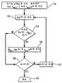
도 7은 본 발명에 따라 무선 네트워크에서 평균 간섭을 최소화하도록 결과적인 안테나 복사 방향들을 결정하는 철저한 과정을 도시하는 흐름도.7 is a flow chart illustrating a thorough process of determining the resulting antenna radiation directions to minimize average interference in a wireless network in accordance with the present invention.
도 8은 본 발명에 따라 무선 네트워크에서 평균 간섭을 최소화하도록 결과적인 안테나 복사 방향들을 결정하는 시뮬레이트 어닐링(simulated annealing) 과정을 도시하는 흐름도.8 is a flow chart illustrating a simulated annealing process for determining the resulting antenna radiation directions to minimize average interference in a wireless network in accordance with the present invention.
도 9는 본 발명에 따른 무선 네트워크의 제 2 실시예에 대한 블록도.9 is a block diagram of a second embodiment of a wireless network in accordance with the present invention.
* 도면의 주요부분에 대한 부호의 설명 *Explanation of symbols on the main parts of the drawings
10 : 이동 스위칭 센터 12 : 스케쥴러10: mobile switching center 12: scheduler
14 : 중앙 안테나 제어기 16 : 기지국 제어기14
18 : 기지국 20 : 안테나 시스템18: base station 20: antenna system
21 : 테스트 수신기21: test receiver
본 발명은 일반적으로 공동채널 간섭을 최소화하도록 무선 네트워크들에서 안테나 복사(radiation)를 조정하는 시스템 및 방법에 관한 것이다.The present invention generally relates to systems and methods for adjusting antenna radiation in wireless networks to minimize cochannel interference.
무선 네트워크가 초기에 설치되거나 확장될 때마다, 전체적인 상업적 동작에 앞서 다양한 무선 파라미터들이 적절한 값들로 동조되어야 한다. 무선 파라미터들의 동조는 무선 주파수(radio frequency, RF) 네트워크 최적화라 칭하여진다. RF 최적화는 전형적으로 기지국 안테나들의 방향과 다운링크(down-link) 전송기들의 전송 전력을 조정하는 것을 포함한다.Each time a wireless network is initially installed or expanded, various wireless parameters must be tuned to appropriate values prior to overall commercial operation. Tuning of radio parameters is called radio frequency (RF) network optimization. RF optimization typically involves adjusting the direction of base station antennas and the transmit power of down-link transmitters.
무선 서비스 제공자들은 가끔 무선 네트워크 내에서 셀(cell)들이나 다른 지형적 영역들의 무선 주파수 안테나 커버 영역을 최적화하는데 시행착오 방법(trial-and-error strategy)에 의존하였다. 시행착오 방법은 각 기지국에 대한 안테나 방향의 실행가능한 배치를 찾을 때까지 반복적인 테스트 운행들을 통해 같은 위치들에서 반복되는 측정들을 요구한다. 테스트 운행은 무선 네트워크의 커버 영역을 통해 운행하면서 위치에 대해 무선 주파수 파라미터들을 측정하도록 장비가 갖추어진 차량으로부터 무선 주파수 측정 샘플들을 취하는 것을 말한다. 테스트 운행 동안 셀들의 클러스터(cluster)에서 기록된 파라미터들의 측정들에 기초하여 시스템 파라미터들을 조정하는 것에 대한 추천들이 이루어진다. 그러나, 시행착오 접근법은 때때로 동작 시스템에 부정확한 추천들이 적용되는 경우 변질되거나 서비스 인터럽트가 일어나게 된다. 시스템 파라미터들에 대한 추천된 변화들이 실시된 이후에, 시스템 성능을 확인하기 위해 전형적으로 다른 테스트 운행이 완료된다. 최근 테스트 운행이 충분한 성능을 나타내지 않았으면, 무선 네트워크 또는 확장은 상업적인 동작으로부터 지연될 수 있고, 또 다른 라운드의 파라미터 조정들이 대응하는 테스트 운행으로 이어진다.Wireless service providers sometimes relied on a trial-and-error strategy to optimize the radio frequency antenna cover area of cells or other topographical areas within a wireless network. The trial and error method requires repeated measurements at the same locations through repeated test runs until a feasible arrangement of antenna directions for each base station is found. Test driving refers to taking radio frequency measurement samples from a vehicle that is equipped to measure radio frequency parameters for a location while driving through the cover area of the wireless network. Recommendations are made for adjusting system parameters based on measurements of parameters recorded in a cluster of cells during a test run. However, trial and error approaches sometimes deteriorate or cause service interruptions when incorrect recommendations are applied to the operating system. After the recommended changes to the system parameters have been made, another test run is typically completed to verify system performance. If a recent test run did not exhibit sufficient performance, the wireless network or extension may be delayed from commercial operation and another round of parameter adjustments lead to the corresponding test run.
무선 네트워크가 적시에 상업적인 동작으로 진행되더라도, 부적절한 무선 주파수 최적화는 무선 네트워크의 용량을 감소시킨다. 무선 주파수 커버영역을 정확하게 최적화시키지 못하면, 주요 집중적인 셀룰러(cellular) 하부구조에 불필요한 지출들이 생기게 된다. 예를 들면, 정확하지 않게 최적화된 무선 시스템을 보상하기 위해 진짜로 필요로 하지 않는 추가 채널 용량이나 추가 셀 사이트들이 부가될 수 있다.Even if the wireless network proceeds with timely commercial operation, improper radio frequency optimization reduces the capacity of the wireless network. Failure to accurately optimize the radio frequency coverage can result in unnecessary expenditures on major intensive cellular infrastructures. For example, additional channel capacity or additional cell sites may be added that are not really needed to compensate for an incorrectly optimized wireless system.
최적화를 위한 시행착오 접근법은 때로 무선 주파수 최적화를 위해 수용가능한 해결법을 구하기 위해 반복적인 또는 다수의 필드 측정들을 수반함으로서 엔지니어링 및 기술적 자원들의 소중한 시간을 낭비한다. 시행착오의 반복 특성은 대형 네트워크들을 처리하는데 있어 이러한 접근법이 어려워지거나 실행불가능하게 만든다. 그래서, 경험 데이터의 우연적 누적 및 시간 소모에 의존하기 보다 최적화의 정확성을 개선할 필요성이 있다.Trial-and-error approaches to optimization waste valuable time in engineering and technical resources, sometimes involving repetitive or multiple field measurements to find acceptable solutions for radio frequency optimization. The iterative nature of trial and error makes this approach difficult or impractical for dealing with large networks. Thus, there is a need to improve the accuracy of optimization rather than relying on accidental accumulation and time consumption of empirical data.
무선 네트워크들이 2세대 무선 네트워크들에서 3세대 무선 네트워크들로 발전되므로, 3세대 네트워크들에서는 안테나 복사 패턴들과 연관된 변수들 및 순열들의 수가 충분히 복잡해질 것으로 기대되기 때문에, 무선 주파수 커버 영역의 최적화를 위해 시행착오 기술들을 적용하는 것은 시대에 뒤떨어진다. 2세대 무선 네트워크들은 주로 하향 경사(down-tilt)라 일반적으로 공지된 수직 방향에서 안테나 방향을 변화시키는 것에 관계한다. 대조적으로, 3세대 무선 네트워크들은 수직 및 수평 방향 모두에서 기지국 안테나 복사 패턴을 변화시킬 수 있을 것으로 기대된다.Since wireless networks have evolved from second generation wireless networks to third generation wireless networks, optimization of the radio frequency coverage area is expected in third generation networks because the number of variables and permutations associated with antenna radiation patterns is expected to be sufficiently complex. The application of trial-and-error techniques is outdated. Second generation wireless networks are primarily concerned with changing the antenna direction in the vertical direction, commonly known as down-tilt. In contrast, third generation wireless networks are expected to be able to vary base station antenna radiation patterns in both the vertical and horizontal directions.
본 발명에 따라, 무선 네트워크에서 무선 주파수(radio frequency) 커버 영역을 조정하는 방법은 신호 파라미터들(예를 들면, 신호 강도들)의 측정을 허용하는 제어 방식으로 안테나들의 안테나 복사(radiation) 방향들을 변화시키는 것을 포함한다. 테스트 수신기는 안테나 복사 방향들이 변할 때 측정 위치들에서 안테나들로부터 신호 파라미터들을 측정한다. 처리 시스템은 측정된 신호 파라미터들에 기초하여 무선 네트워크 또는 그 세그먼트(segment)에서 안테나들의 각각에 대한 결과적인 안테나 복사 방향을 결정한다.According to the present invention, a method of adjusting a radio frequency cover area in a wireless network is directed to the antenna radiation directions of the antennas in a controlled manner that allows the measurement of signal parameters (eg signal strengths). It includes changing. The test receiver measures signal parameters from the antennas at the measurement locations when the antenna radiation directions change. The processing system determines the resulting antenna radiation direction for each of the antennas in the wireless network or its segment based on the measured signal parameters.
다운링크(downlink) 안테나들의 결과적인 안테나 복사 방향들은 무선 네트워크에 걸쳐 선택된 측정 위치들에 대해 테스트 수신기에서의 캐리어-대-간섭이 충분하거나, 최대화되거나, 또는 다른 수용가능한 성능 표준을 만족시키도록 안테나 복사 방향들이 정해진다. 안테나 복사 방향은 방향성 또는 하향 기울기의 복사 패턴이 수신되거나 전송된 전자기 신호들에 대해 최대 이득을 갖는 방위각, 하향 기울기 각도, 또는 그 모두를 의미한다. 상기 방법의 시스템 특성들 및 그와 연관된 데이터 구조는 종래의 시행착오 접근법에 따라 필드 측정들을 취하는 회귀적이거나 반복적인 특성을 제거함으로서 무선 주파수 최적화의 효율을 증가시킨다.The resulting antenna radiation directions of downlink antennas are such that the carrier-to-interference at the test receiver is sufficient, maximized, or otherwise satisfies other acceptable performance standards for the measurement locations selected over the wireless network. Radiation directions are determined. Antenna radiation direction means an azimuth, downward tilt angle, or both, in which a radiation pattern of directional or downward slope has a maximum gain with respect to received or transmitted electromagnetic signals. The system characteristics of the method and the data structure associated therewith increase the efficiency of radio frequency optimization by eliminating the regressive or repetitive characteristic of taking field measurements according to conventional trial and error approaches.
본 발명에 따라, 도 1은 통신선들을 통해 다수의 기지국 제어기들(16)에 결합된 이동 스위칭 센터(mobile switching center)(10)를 포함하는 무선 네트워크를 도시한다. 기지국 제어기(16)는 기지국(18) 및 안테나 시스템(20)에 결합된다. 실제로, 기지국 제어기(16), 기지국(18), 및 안테나 시스템(20)은 무선 주파수 커버 영역을 통해 지형적 구역에 서비스를 제공하는 셀 사이트를 형성하도록 함께 위치한다.1 shows a wireless network comprising a
이동 스위칭 센터(10)는 일반적으로 기지국 제어기들(16)과 함께 스위칭 및 제어 기능들을 지지하기에 적절한 임의의 전기통신 스위치를 구비한다. 실제로, 이동 스위칭 센터(10)는 이동 스위칭 센터(10)를 공중 교환 전화 네트워크(public switched telephone network, PSTN), 무선 네트워크, 또는 그 둘 모두와 연결시키는 적어도 하나의 다른 전기통신 스위치와 통신한다.
이동 스위칭 센터(10)는 두가지 면에서 상업적으로 이용가능한 많은 표준 스위치들과 다르다. 먼저, 이동 스위칭 센터(10)는 각 안테나 시스템(20)의 안테나 방향을 예정하는 스케쥴러(scheduler)(12)를 포함한다. 두 번째로, 이동 스위칭 센터(10)는 스케쥴러(12)와 통신하는 중앙 안테나 제어기(14)를 포함한다. 중앙 안테나 제어기(14) 및 스케쥴러(12)는 이동 스위칭 센터(10)의 위치로부터 안테나 시스템들(20)을 제어하도록 소프트웨어 지시들 및 호환가능한 처리 시스템을 구비한다.The
중앙 안테나 제어기(14)는 기지국 제어기(16)를 통해 안테나 시스템들(20)에 명령 신호들을 전달하도록 채택된다. 명령 신호들은 각 기지국 제어기(16)로부터 기지국(18)을 통해 각 안테나 시스템(20)에 전해진다. 중앙 안테나 제어기(14)는 임의의 주어진 순간 시간에서 대응하는 안테나 시스템(20)의 각 안테나의 복사 방향을 제어하는데 명령 신호들을 사용한다. 중앙 안테나 제어기(14)는 일반적으로 각 측정 위치에 대해 이용가능한 안테나 복사 방향들의 한정된 범위내에서 안테나 복사 방향을 변화시킨다. 중앙 안테나 제어기(14)는 양호하게 각 테스트 위치에서 적어도 한번 안테나 방향 상태들의 한정된 범위를 통해 안테나 복사 방향의 피크 이득을 회전시킨다. 중앙 안테나 제어기(14)는 스케쥴에 따라 각 안테나 시스템(20)에 명령 신호들을 전달하므로, 제어되는 각 안테나 시스템(20)의 안테나 복사 방향이 협력하여 조정될 수 있다.The
스케쥴러(12)는 각 안테나의 복사 방향으로 좌표가 변하는 제 1 리스트 및 제 2 리스트를 포함한다. 제 1 리스트 및 제 2 리스트는 함께 스케쥴(schedule)이라 칭하여진다. 제 1 리스트는 안테나 측정 순서로 무선 네트워크 내의 안테나들을 조직화한다. 안테나 측정 순서는 다른 안테나들로부터의 전자기 전송들이 측정되는 순차를 결정한다.The
제 2 리스트는 각 안테나에 대한 복사 방향 측정 순서를 조직화한다. 방향 측정 순서는 다른 복사 방향들에서 각 안테나로부터의 전자기 전송들이 측정되는 순차를 결정한다. 제 1 및 제 2 리스트들에 따라, 이동 스위칭 센터(10)에 위치하는 중앙 안테나 제어기(14)는 대응하는 안테나 복사 패턴을 주어진 방향으로 조정하도록 각 기지국(18)에 명령 신호들을 전한다. 그래서, 임의의 순간에, 안테나 복사 패턴의 피크 이득은 일반적으로 특정한 방향을 지시하고 있다. 스케쥴은 일반적으로 각 안테나의 가능한 안테나 복사 방향들 및 기지국들(18)의 수와 연관된 조합들을 넘는 저장 크기를 요구한다.The second list organizes the radiant direction measurement order for each antenna. The direction measurement order determines the sequence in which electromagnetic transmissions from each antenna in different radiation directions are measured. According to the first and second lists, the
스케쥴은 각 안테나 복사 패턴이 주어진 방향을 지시하며 머물게 되는 기간을 결정한다. 스케쥴의 바람직한 구성에 따라, 중앙 안테나 제어기(14)는 각각 순차적으로 가능한 복사 방향 상태들의 범위 내에서 각 안테나를 주사하므로, 테스트 수신기(21)는 임의의 순간에 한 안테나로부터만 수신하게 된다. 중앙 안테나 제어기(14)의 제어기 포인터가 스케쥴에서 최종 안테나의 최종 복사 방향에 도달한 이후에, 제어기 포인터는 다음 안테나의 제 1 방향으로 재설정된다. 즉, 다음 안테나에 대한 다음 측정 싸이클이 시작된다. 측정 과정은 측정 위치들의 전체 그룹이 커버될 때까지, 또는 적어도 측정 위치들 중에서 통계적으로 충분한 부분이 선택된 검증 레벨을 만족시키도록 커버될 때까지 각 측정 위치에서 제 1 안테나의 제 1 복사 방향으로부터 최종 안테나의 최종 복사 방향까지 전체 테스트 운행 동안 이어진다. 무선 주파수 최적화 방법이 무선 네트워크의 일부에만 적용되는 경우, 모든 측정 위치들이 커버될 필요는 없다.The schedule determines how long each antenna radiation pattern stays pointing in a given direction. In accordance with the preferred configuration of the schedule, the
테스트 운행 동안 수집된 측정 신호 파라미터들(예를 들면, 신호 강도)의 데이터는 각 안테나의 결과적인 안테나 복사 방향을 결정하는데 사용된다. 안테나 복사 방향들이 결과적인 안테나 복사 방향들로 정렬되면, 전체적인 무선 네트워크 지형적 커버 영역에 걸쳐 집적된 결과적인 전체 캐리어-대-간섭 비율은 최대화되거나 적어도 실질적인 무선 주파수 설계 목적들을 이루는데 충분해진다.Data of measurement signal parameters (eg, signal strength) collected during the test run is used to determine the resulting antenna radiation direction of each antenna. If the antenna radiation directions are aligned with the resulting antenna radiation directions, the resulting overall carrier-to-interference ratio integrated over the entire wireless network topographical coverage area is maximized or at least sufficient to achieve substantial radio frequency design goals.
안테나 시스템(20)은 일반적으로 위상 어레이 안테나(phased-array antenna) 또는 동적으로 제어가능한 복사 패턴을 갖는 다른 안테나를 구비한다. 안테나 복사 방향은 위상 어레이 안테나를 포함하여 임의의 설계의 방향성 안테나에서 메인 로브(main lobe)의 피크 이득 방향을 칭한다. 위상 어레이 안테나는 중앙 안테나 제어기(14)나 또 다른 안테나 제어기에 응답해 안테나 시스템(20)의 복사 패턴을 변경하기 위해 위상 쉬프터(phase shifter)들이나 다른 신호 처리 기술들을 포함한다. 위상 어레이 안테나를 통해, 안테나의 복사 방향 뿐만 아니라 안테나의 복사 패턴 형상이 전자적으로 변화될 수 있다. 따라서, 네트워크 작동자는 지형이나 통화량에 대해 네트워크 성능을 최적화하거나 증진시킬 수 있다. 본 발명에 따라, 안테나 복사를 조정하는 시스템 및 시스템적 방법은 위상 어레이 안테나들의 복사 패턴 방향 변화들에 탄력성을 증진시키는데 적절히 사용된다.
이론적으로, 각 안테나는 주어진 범위 내에서 임의의 복사 방향을 가정할 수 있으며; 안테나 복사 방향의 영역은 연속적이다. 그러나, 실제로, 상업적으로 이용가능한 많은 안테나 시스템(20)들은 안테나 복사 방향들에 대해 이산적인 복사 상태들 만을 제공한다. 안테나 복사 방향들 및 복사 방향 변화들은 중앙 안테나 제어기(14)로부터의 명령 신호들에 응답해 이산적인 상태들로 동조될 수 있다. 복사 상태들의 변위는 각 위치에서 요구되는 측정 범위를 제한하도록 일반적으로 원하는 각 안테나 시스템(20)의 무선 주파수 커버영역에 기초하여 선택될 수 있다. 예를 들어, 안테나 시스템(20)이 다중섹터(multi-sector) 셀의 특정한 섹터에 서비스를 제공하도록 예정되면, 안테나 복사 방향들의 범위는 대응하는 안테나 시스템(20)에 대해 그 섹터로(또는 그에 약간 벗어나) 제한될 수 있다. 안테나 복사 패턴들의 범위를 제한하는 것은 결과적인 복사 방향들을 결정하는 데이터 처리 부담을 줄이고 측정 처리의 기간을 감소시킨다. 다수의 안테나들이 각 기지국과 연관되면, 각 안테나는 특정한 시간에 전자기 신호들을 복사하고 있는 활성 안테나들의 동시 또는 일련의 식별을 허용하도록 기지국에 의한 전송에 대응하는 안테나 식별자를 갖는다.In theory, each antenna can assume any radiation direction within a given range; The area in the antenna radiation direction is continuous. In practice, however, many commercially
테스트 수신기(21)는 기지국(18)으로부터 전송된 다운링크 전자기 신호를 수신하는 수신기를 포함한다. 전송된 다운링크 전자기 신호는 안테나 사이트에 있는 안테나 시스템(20)으로부터 비롯된다. 기지국(18)은 활성적으로 복사하는 안테나 시스템들(20)과 그에 연관된 복사 방향들의 식별을 위해 유일한 기지국 식별자 코드를 전송하도록 적응된다. 테스트 수신기(21)는 추후 참고하도록 대응하는 신호 파라미터 측정들과 함께 기지국 식별자 코드들의 기록을 용이하게 한다. 안테나 시스템(20)은 양호하게 동축 케이블과 같은 전송 매체를 통해 기지국(18)의 대응하는 전송 무선 주파수 포트에 연결된다. 전자기 신호의 신호 파라미터(예를 들면, 신호 강도)를 측정하는 신호 파라미터 측정자는 테스트 수신기(21)에 결합된다. 수신된 신호 강도 표시자(received signal strength indicator, RSSI)와 같은 신호 파라미터 측정기는 측정된 신호 강도들을 기록 매체에 기록하는 기록기를 포함한다. 기록기는 신호 강도 측정기에 적절한 아날로그 또는 디지털 인터페이스를 갖춘 범용 컴퓨터를 포함한다. 측정가능한 신호 강도는 배경 잡음을 넘는 신호 강도를 갖는 임의의 신호를 칭한다. 측정가능한 신호에는 적절한 잡음형을 갖는 테스트 수신기(21)에 의해 검출 및 측정이 행해진다. 테스트 수신기(21)는 상술된 스케쥴에 의해 규정된 바와 같이 각 측정 위치에서 체류 시간을 요구한다.The
기록기는 스케쥴에 의해 결정된 방법과 포맷으로 수신기로부터 수신된 데이터 샘플들을 기록 매체에 기록한다. 기록 매체는 기대되는 데이터 샘플들을 유지하는데 요구되는 만큼의 레지스터들로 구성된 버퍼와 연관된다. 데이터 샘플들은 다른 측정 위치들 및 다른 안테나 사이트들에 대응하는 신호 파라미터값들(예를 들면, 신호 전력이나 신호 강도)을 포함한다. 그러므로, 각 버퍼에서 레지스터들의 수는 적어도 다른 안테나 사이트들에 대응하는 안테나들에 지정된 안테나 복사 방향들 만큼 되어야 한다.The recorder records the data samples received from the receiver in the recording medium in the method and format determined by the schedule. The recording medium is associated with a buffer of as many registers as required to hold the expected data samples. The data samples include signal parameter values (eg, signal power or signal strength) corresponding to different measurement locations and different antenna sites. Therefore, the number of registers in each buffer should be at least as much as the antenna radiation directions specified for the antennas corresponding to the other antenna sites.
기록 매체의 총 저장 크기는 다른 요소들 중에서 안테나들의 수(n), 각 안테나에 대한 안테나 복사 방향 상태들의 수(l), 및 위치들의 수(m)에 알맞은 크기이다. 수학적으로 표시되면, 테스트 운행 동안 측정되는 데이터 샘플들은 n x m x l이다.The total storage size of the recording medium is a size suitable for the number n of antennas, the number l of antenna radiation direction states for each antenna, and the number m of positions, among other factors. Mathematically, the data samples measured during the test run are n x m x l.
도 2는 본 발명에 따라 무선 네트워크에서 안테나 복사를 조정하는 방법을 설명한다. 단계(S100)에서 시작되어, 안테나 그룹의 안테나 복사 방향은 안테나 복사 방향의 범위에 걸쳐 변한다(즉, 순환된다). 안테나 복사 방향은 양호하게 이동 스위칭 센터(10)에 위치하는 중앙 안테나 제어기(14)에 의해 제어되지만, 다른 방법의 실시예에서는 안테나 복사 방향이 공통적인 기준 신호에 동기화되어 각 위치에 있는 국부적 안테나 제어기를 포함하는 그룹에 의해 제어된다.2 illustrates a method of adjusting antenna radiation in a wireless network in accordance with the present invention. Beginning at step S100, the antenna radiation direction of the antenna group changes over (ie, circulates) over a range of antenna radiation directions. The antenna radiation direction is preferably controlled by the
안테나 복사 싸이클은 안테나가 상태 범위내에서 제1 상태로부터 최종 상태까지 복사 방향을 변화시키는 기간을 나타낸다. 안테나 제어기 또는 중앙 안테나 제어기(14)는 양호하게 측정 위치와 동일한 테스트 수신기 위치에 있는 테스트 수신기(21)의 고정 또는 이동 기간에 알맞도록 안테나 복사 싸이클을 설정한다. 예를 들어, 각 안테나 시스템의 주사 속도가 이동 속도 보다 훨씬 더 크면, 측정 위치를 통과하는 이동 테스트 수신기에 대해서는 측정 에러가 무시된다. 그래서, 중앙 안테나 제어기(14)는 안테나 복사 싸이클에 따라 각 안테나의 각기 복사 방향 변화를 조정하기 위한 일반적인 스케쥴을 정한다.The antenna radiation cycle represents a period during which the antenna changes the radiation direction from the first state to the final state within the state range. The antenna controller or
단계(S102)에서, 테스트 수신기(21)는 다수의 측정 위치에서 변하는 안테나 복사 방향에 대한 신호 파라미터를 측정한다. 예를 들면, 테스트 수신기(21)는 복사 싸이클 동안 선택된 각 측정 위치에 있는 안테나로부터 신호 파라미터(예를 들면, 신호 강도)를 측정한다. 측정된 신호 파라미터는 신호 강도를 포함하지만, 다른 방법의 실시예에서는 측정된 신호 파라미터가 신호-대-잡음, 캐리어-대-간섭, 프레임-에러 비율, 비트 에러 비율, 또는 또 다른 무선 주파수 성능 측정치를 포함할 수 있다. n개 기지국(18) 각각은 셀(cell)이라 칭하여지는 지형적 커버 영역에 서비스를 제공한다. 전체적으로, m개 측정 위치는 네트워크의 전체적인 커버 영역을 나타내도록 정의된다. 그에 대응하여, 측정 데이터를 기록하는데 요구되는 m개의 버퍼가 있다. 버퍼의 저장 용량은 각 안테나가 만들 수 있는 방향 상태의 수에 의해 결정된다. 단계(S102)의 측정에서, 테스트 수신기(21)는 일반적으로 적어도 각 안테나의 한 주사 주기 또는 싸이클 동안 각 측정 위치에 남아있다.In step S102, the
조정 방법은 이어지는 계산에서 단지 네트워크의 표지 채널(beacon channel)을 측정하여 고려함으로서 간략화될 수 있다. 표지 채널은 일반적으로 각 셀의 무선 주파수 커버영역을 나타낸다. 예를 들면, IS-95에서 설명된 바와 같은 GSM(Group Special Mobile)의 방송 제어 채널(broadcast control channel, BCCH) 및 CDMA(code-division multiple access)의 파일럿 채널(pilot channel)이 표지 채널이다.The coordination method can be simplified by only taking into account the beacon channel of the network in the following calculation. The beacon channel generally represents the radio frequency coverage of each cell. For example, a broadcast control channel (BCCH) of Group Special Mobile (GSM) and a pilot channel of code-division multiple access (CDMA) as described in IS-95 are indicator channels.
단계(S104)에서, 처리 시스템은 양호하게 각 측정 위치에 대응하는 위치 측정 매트릭스와 같이, 측정된 신호 파라미터를 데이터 구조로 조직화한다. 단계(S106)에서, 처리 시스템은 데이터 구조(예를 들면, 위치 측정 매트릭스)에 기초하여 무선 네트워크(또는 그의 세그먼트)에서 각 안테나에 대한 안테나 복사 상태의 범위내에서 결과적인 안테나 복사 방향을 결정한다.In step S104, the processing system preferably organizes the measured signal parameters into a data structure, such as a position measurement matrix corresponding to each measurement position. In step S106, the processing system determines the resulting antenna radiation direction within a range of antenna radiation states for each antenna in the wireless network (or segment thereof) based on the data structure (e.g., location measurement matrix). .
양호한 실시예에서, 안테나 복사 방향은 피크 이득이 관찰되는 하향 기울기(down-tilt) 각도 및 방위각을 나타내는 2차원 벡터로 정의된다. 또 다른 양호한 실시예에서, 결과적인 안테나 복사 방향에 대한 후보는 복사의 메인 로브(main lobe) 중 피크 이득을 나타내는 중앙 벡터, 메인 로브의 제 1 제한을 나타내는 제 1 제한 벡터, 및 메인 로브의 제 2 제한을 나타내는 제 2 제한 벡터를 포함하는 것으로 정의된다. 제 1 및 제 2 제한은 메인 로브의 피크 크기 이하에서 일부 지정된 크기의 복사 레벨에 대응한다.In a preferred embodiment, the antenna radiation direction is defined as a two-dimensional vector representing the down-tilt angle and azimuth angle at which the peak gain is observed. In another preferred embodiment, the candidate for the resulting antenna radiation direction is a center vector representing the peak gain of the main lobe of radiation, a first restriction vector representing the first restriction of the main lobe, and a first of the main lobe. It is defined to include a second restriction vector that represents the two constraints. The first and second limits correspond to radiation levels of some specified size below the peak size of the main lobe.
처리 시스템은 양호하게 다운링크 장비 사이트들에서 각 안테나에 대해 대응하는 결과적인 안테나 복사 방향을 구하도록 선택된 측정 위치들에 걸쳐 간섭 신호 강도의 시스템 전체의 최소 평균(또는 그의 근사치)을 결정한다. 부가하여, 처리 시스템은 대응하는 결과적인 안테나 복사 방향을 구하도록 선택된 모든 측정 위치에 걸쳐 배경 잡음을 포함함으로서 간섭 신호 강도의 시스템 전체의 최소 평균을 계산할 수 있다. 다른 방법의 실시예에서는 무선 네트워크의 결과적인 안테나 복사 방향을 구하기 위해 시스템 전체의 간섭 레벨 대신에 시스템 전체의 최대 캐리어-대-간섭 비율(또는 그의 근사치)이 평가된다.The processing system preferably determines the minimum average (or approximation) of the system overall of the interfering signal strength over the selected measurement locations to obtain the corresponding resulting antenna radiation direction for each antenna at the downlink equipment sites. In addition, the processing system may calculate the minimum average of the overall system of interference signal strength by including background noise across all measurement positions selected to find the corresponding resulting antenna radiation direction. In another embodiment, the maximum carrier-to-interference ratio (or an approximation) of the entire system is evaluated instead of the overall system interference level to obtain the resulting antenna radiation direction of the wireless network.
본 발명의 조정 방법은 무선 네트워크의 무선 주파수 커버영역을 효과적으로 조정하도록 단련된 프레임워크(framework)를 제공하기 위해 측정 과정과 수학적 데이터 처리를 조합한다. 중앙 안테나 제어기(14)와 스케쥴러(12)는 측정 동작을 제어하므로, 비록 무선 네트워크의 적용가능한 모든 측정 위치가 양호하게 단 1회만 측정되더라도 무선 주파수 증진이 아직까지 가능하다.The tuning method of the present invention combines the measurement process and the mathematical data processing to provide a framework that has been trained to effectively adjust the radio frequency coverage of the wireless network. Since the
도 3a 내지 도 3c는 각각 4개의 안테나 위치를 포함하는 무선 네트워크(56)에서 결과적인 안테나 복사 방향(54)의 잠재적인 배치를 나타내는 도면을 도시한다. 안테나 위치는 (S1 내지 S4)로 칭하여지고, 위치에 대한 안테나 복사 방향(54)은(e1 내지 e4)로 칭하여진다. 각 도면의 안테나 복사 방향(54)이 다른 것을 제외하 면, 도 3a 내지 도 3c에는 똑같은 측정 위치(50)를 갖는 똑같은 통신 시스템이 도시된다. 측정 위치(50)는(x0 내지 x5)로 칭하여진다.3A-3C show diagrams illustrating the potential placement of the resulting
각 지형 표시는 무선 시스템내의 측정 위치(50) 그룹에 대해 대응하는 평균 간섭값을 갖는다. 평균 간섭은 또한 캐리어-대-간섭 비율의 항으로 표시될 수 있고, 여기서 간섭은 모두 캐리어 대역폭내에서 측정가능한 전자기 에너지(예를 들면, 잡음)를 포함한다. 본 발명에 따라, 처리 시스템은 측정 위치 그룹에 대해 최하의 평균 간섭(또는 그의 근사치)를 식별하고, 최하의 평균 간섭(또는 그의 근사치)과 연관된 결과적인 다운링크 안테나 복사 방향(54)을 선택한다. 최하의 평균 간섭(또는 그의 근사치)은e라 칭하여지는 벡터로, 또는 도 3a 내지 도 3c에 도시된 바와 같이 도면에서 참고 번호(29)로 표시될 수 있다. 벡터e는 모든 안테나 위치에 대한 시스템 전체의 해답, 또는 측정 위치의 그룹이 무선 주파수 무선 네트워크 성능을 나타내는 한 선택된 위치를 나타낸다. 또한, 각 측정 위치는 특정한 무선 네트워크의 무선 주파수 실행 목적을 만족시키도록 탄력적으로 시스템 전체의 해답을 맞추기 위해 특정한 가중치 계수에 따라 의미가 지정될 수 있다.Each terrain representation has a corresponding average interference value for the group of
도 4는 도 2의 단계(S102)를 더 상세히 도시한다. 테스트 수신기(21)는 도시된 바와 같이 대응하는 복사 방향 순열을 발생하는 안테나로부터 신호 강도를 측정한다. 제 1 측정 위치(58)에서, 테스트 수신기(21)는 제 1 안테나(68), 제 2 안테나(70), 및 제 n 안테나(72)로부터 신호 강도를 측정한다. 제 1 안테나(68), 제 2 안테나(70), 및 제 n 안테나(72)는 양호하게 시간-분할 멀티플렉스 방식으로 스케쥴에 따라 각각 순차적으로 측정된다. 그러나, 다른 방법의 실시예에서는 단일 수신기 보다는 다른 주파수에 동조된 다수의 수신기를 사용해 신호 강도의 동시 측정이 이루어질 수 있다.4 shows step S102 of FIG. 2 in more detail. The
또 다른 방법의 실시예에서, 단일 확산 스펙트럼 수신기는 연관된 기지국에 의한 전송을 위해 유일한 식별자 코드를 제공할 수 있는 다른 안테나로부터 다수 채널의 동시 측정을 허용하도록 다른 의사-랜덤(pseudo-random) 잡음 코드나 직교 코드(orthogonal code)를 수신한다. 다른 안테나는 공통된 기지국이나 공통된 위치와 연관될 수도 있다. 도 4에서는 제 1 측정 위치(58)에서 시작되어, 복사 방향 1.1 내지 복사 방향 1.L로 제 1 싸이클(76)을 통해 안테나 복사 방향이 순환될 때 제 1 안테나(68)가 측정된다. 제 1 안테나(68)의 측정에 이어서, 테스트 수신기(21)는 제 2 안테나(70)가 2.1 내지 2.L로 복사 방향(또는 방향 상태)의 제 2 싸이클(78)을 통해 순환될 때, 제 1 측정 위치(58)에서, 제 2 안테나(70)로부터 복사된 신호 강도를 측정한다. 제 2 안테나(70)의 측정이 완료되면, 처리는 복사 패턴 n.1 내지 n.L의 제 n 싸이클(80)을 갖는 제 n 안테나(72)가 제 1 측정 위치(58)에서 측정될 때까지 계속된다. 제 1 측정 위치(58)에 대한 총 싸이클은 한 주사 주기(82)와 똑같다.In another embodiment of the method, a single spread spectrum receiver may employ other pseudo-random noise codes to allow simultaneous measurement of multiple channels from other antennas that may provide a unique identifier code for transmission by an associated base station. Or receive an orthogonal code. Other antennas may be associated with a common base station or a common location. In FIG. 4, the
제 1 측정 위치(58)에 이어서, 테스트 수신기(21)는 제 1 안테나(68)가 제 1 싸이클(76)을 통해 진행되고, 제 2 안테나(70)가 제 2 싸이클을 통해 진행되고, 또한 제 n 안테나(72)가 제 n 싸이클을 통해 진행될 때 제 1 안테나(68), 제 2 안테나(70), 및 제 n 안테나(72)가 순차적으로 측정되는 제 2 측정 위치(60)로 이동된다. 처리는 제 m 측정 위치(64)까지의 선택된 모든 측정 위치 및 각 안테나의 모 든 싸이클이 커버될 때까지 계속된다.Following the
도 5는 도 2의 단계(S104)를 더 상세히 도시한다. 도 5는 측정된 데이터를 조직화하고 무선 주파수 커버영역을 조정하도록 구성된 데이터 포맷의 수학적인 표현을 나타낸다. 구성된 데이터 포맷은 테스트 수신기(21)의 각 위치에 대한 위치 측정 매트릭스(100)를 포함한다. 각 위치 측정 매트릭스(100)는 무선 네트워크에서 각 안테나에 대한 다수의 안테나 방향의 신호 파라미터(즉, 신호 전력) 측정치를 포함하는 어레이를 구비한다. 그러나, 측정 위치에서 측정가능한 신호를 제공하지 않는 안테나는 위치 측정 매트릭스(100)에서 무시될 수 있다. 데이터 구조는 양호하게 기록 매체에 저장되고, 각 안테나에 대한 최적 안테나 복사 방향을 찾는데 사용된다.5 shows step S104 of FIG. 2 in more detail. 5 shows a mathematical representation of a data format configured to organize measured data and adjust radio frequency coverage. The configured data format includes a
측정된 신호 파라미터에 대한 다음의 수학적 표현은 도 5의 위치 측정 매트릭스(100)에 포함된다. Si(x,ei)는 안테나 i에 의해 전송되고 측정 위치 x에서 수신된 신호 전력을 나타내고, 여기서 ei는 전송 안테나 i의 방향을 칭한다. 복사 방향 ei는 ei가 eij로 되도록 첨자 j를 취하고, 여기서 i는 전송 안테나 식별자를 나타내고 j는 전송 안테나 i의 방향 상태를 나타낸다. S의 첨자 i는 다운링크 안테나의 신원을 나타내고, 이는 측정 위치 x에서 신호 전력 측정의 소스가 된다. 단 하나의 다운링크 안테나 i가 대응하는 각 기지국(18)과 연관되면, 안테나 i는 대응하는 기지국(18)의 신원을 참고하는데 사용될 수 있다. 단일 위치에 하나 이상의 안테나와 기지국(18)이 위치할 수 있다. 안테나가 단일 기지국과 연관된 다른 안테나로부터 독립적으로 동작하면, 각 독립 안테나(예를 들면, 섹터 안테나)는 안테나 식별자가 테스트 수신기에 의해 활성 안테나의 식별을 용이하게 하도록 요구한다. ei의 입체각은 다음의 식에 의해 정의되는 이차원 벡터이다:The following mathematical representation of the measured signal parameter is included in the

여기서, θi각과 φi각은 각각 안테나 복사 방향의 수직각 및 방위각을 칭한다. 각 안테나는 명확하게 정의된 기준 방향을 갖고 ei는 안테나 i의 대응하는 기준 방향에 대해 측정되는 것으로 가정한다. 예를 들면, 섹터화된 셀이나 또 다른 적절한 구성에서, 각 안테나 i는 다음의 식에 의해 정의되는 소정의 복사 방향 범위를 갖는다:Here, θi angle and φi angle refer to the vertical angle and azimuth angle of the antenna radiation direction, respectively. It is assumed that each antenna has a clearly defined reference direction and ei is measured with respect to the corresponding reference direction of antenna i. For example, in a sectorized cell or another suitable configuration, each antenna i has a predetermined radiant direction range defined by the following equation:


여기서, Li 및 Ui는 각각 안테나 i의 제 1 한계(예를 들면, 하단경계) 및 제 2 한계(예를 들면, 상단경계)를 칭한다. 위치 x에서 이동국은 스테이션 i로부터 다음의 신호 순차를 수신하여야 한다:Here, Li and Ui refer to the first limit (eg, bottom boundary) and the second limit (eg, top boundary) of antenna i, respectively. At position x the mobile station should receive the following signal sequence from station i:

여기서, i = 1, 2, ..., n이고, 각 안테나는 q 방향이라 가정한다. 소정의 위치에 대해, Si는 e에만 의존한다. 그러므로, 다른 안테나로부터의 신호는 순차적으로 수신될 수 있다. 안테나 사이의 복사 방향 주사의 동기화 때문에, 측정 위치 x에서의 테스트 수신기(21)는 양호하게 도 5에 설명된 위치 측정 매트릭스(100)에 따라 기록한다.Here, i = 1, 2, ..., n, and each antenna is assumed to be in the q direction. For a given location, Si depends only on e. Therefore, signals from other antennas can be received sequentially. Because of the synchronization of the radiation direction scan between the antennas, the
유효한 위치 측정 매트릭스(100)에 설명된 표현에서, 테스트 수신기(21)는 단일 주사 주기와 같거나 큰 기간 동안 각 측정 위치 x에 거주한다. 주사 주기는 소정의 측정 위치에서 복사 방향 싸이클의 합과 같다. 각 안테나 싸이클은 측정 위치에서 측정가능한 신호를 만드는 대응하는 안테나에 대해 q개의 가능한 복사 방향의 완전한 범위를 칭한다. i = 1, 2, ..., n에 대해, j = 1, 2, ..., q를 갖는 입체각 eij의 모든 값들은 다음의 식으로부터 구해진다:In the representation described in the effective

각 측정 위치에서, 위치 측정 매트릭스(100)는 양호하게 도 5의 데이터 구조에 따라 기록된다. m개 측정 위치에는 m개 매트릭스의 똑같은 데이터 구조가 있다. m개 매트릭스의 집합은 3차원 블록을 나타내고, 이는 탐색 규칙이 제공되는 경우, 모든 위치에 대해 적절한 안테나 방향을 찾을 수 있게 한다.At each measurement position, the
도 5의 위치 측정 매트릭스(100)에서 각 로우(row)는 다른 다운링크 안테나를 나타낸다. 각 측정 매트릭스 위치의 로우는 첨자 S와 첨자 e로 식별되는 안테나를 칭한다. 실제로, 한 다운링크 안테나는 대응하는 기지국(18)의 다운링크 전송과 연관된다. 데이터 구조의 컬럼(column)은 컬럼 사이에서 방향 변화의 균일한 증가를 나타낸다. 또한, 각 컬럼은 다른 안테나의 모든 안테나 방향이 똑같은 방향과 마주 대하도록 배열된다. 즉, 예를 들어 제 1 컬럼은 방위각으로 0°의 안테나 복사 방향을 나타내는 반면, 제 2 컬럼은 10°의 안테나 복사 방향을 나타낸다.Each row in the
일반적으로, 안테나 복사 방향은 복사 패턴의 메인 로브의 피크 이득과 일치한다. 피크 이득은 유일하게 복사 패턴의 메인 로브내에서 단일차원 또는 다중차원 범위로 정의된다. 복사 패턴의 형상은 가상적으로 본 발명을 실시하도록 사용된다. 예를 들어, 단 하나의 방위 평면만이 고려되는 경우, 카디오이드(cardioid) 복사 패턴의 메인 로브는 복사 패턴 이득의 반전력점(피크 이득 보다 3dB 더 낮은)에 대응하는 한쌍의 방위각에 의해 정의된다.In general, the antenna radiation direction matches the peak gain of the main lobe of the radiation pattern. Peak gain is defined solely as a single or multidimensional range within the main lobe of the radiation pattern. The shape of the radiation pattern is used to practice the invention virtually. For example, if only one azimuth plane is considered, the main lobe of the cardioid radiation pattern is defined by a pair of azimuth angles corresponding to the reversal point of radiation pattern gain (3 dB lower than peak gain). .
안테나 복사 방향은 규정상 0 내지 360도 범위의 방위각과 0 내지 90도 범위의 수직각에 따라 지정된다. 안테나 복사 패턴은 다운링크 방위각, 다운링크 하향기울기 각도, 또는 그 둘 모두를 포함할 수 있다. 양호한 구성에서, 각 로우는 0과 360도 사이의 간격수와 같은 엔트리(entry)의 수를 갖는다. 간격수는 양호하게 가능한 방향 상태의 수에 알맞다.The antenna radiation direction is specified according to the azimuth angle in the range of 0 to 360 degrees and vertical angle in the range of 0 to 90 degrees. The antenna radiation pattern may include a downlink azimuth angle, a downlink downhill angle, or both. In a preferred configuration, each row has a number of entries, such as an interval between 0 and 360 degrees. The number of intervals suitably matches the number of possible orientation states.
도 5는 단일 측정 위치 x에 대한 캐리어-대-간섭(또는 신호-대-잡음비)을 계 산하기에 충분한 정보를 포함한다. 대조적으로, 도 6은 통신 시스템내의 모든 x값에 대해 최소 간섭(또는 그의 근사치)을 결정하기에 충분한 정보를 위치 매트릭스에서 포함한다. 여기서는 측정 위치 x1이 위치 S1에 의해 서비스가 제공되기 때문에, 설명을 위하여 안테나 위치 또는 기지국 S1이 배제되므로, S1은 간섭 전송 소스로 정의되지 않는다.5 contains enough information to calculate carrier-to-interference (or signal-to-noise ratio) for a single measurement position x. In contrast, FIG. 6 includes information in the location matrix sufficient to determine the minimum interference (or an approximation thereof) for all x values in the communication system. Since the measurement position x1 is serviced by the position S1 , the antenna position or the base station S1 is excluded for explanation, so S1 is not defined as an interference transmission source.
도 6에 도시된 각 2차원의 위치 측정 매트릭스(100)가 높이와 폭을 갖기 때문에, 각 매트릭스의 깊이는 측정 위치 x의 최대수 m에 의해 결정된다. 도 6의 매트릭스 중 하단 그룹은 도 6에 도시된 상단 그룹의 매트릭스와 유사한 배경 잡음 매트릭스를 도시한다. Ni(x,eij)는 측정된 잡음 전력을 나타내고, 여기서 N의 첨자 i는 q개의 가능한 안테나 복사 방향과 n개의 가능한 안테나 중에서 안테나 복사 방향 eij으로 측정 위치 x의 기지국 i으로부터의 잡음 전력을 나타낸다. x는 단순히 m개의 가능한 측정 위치 중에서 특정한 특정 위치를 나타낸다. 각각의 배경 잡음 매트릭스(104)는 무선 네트워크내의 무선 간섭을 나타내도록 각 테스트 위치에 대해 생성되어 측정 위치 x에 대해 똑같은 값을 갖는 대응하는 위치 측정 매트릭스(100)에 부가될 수 있다. 그러나, 일부 환경에서는 배경 잡음 매트릭스가 방향적으로 균일하므로, 평균 시스템 전체의 간섭 레벨을 계산할 때의 정확도를 떨어뜨리지 않고 정보를 스칼라 포맷으로 압축할 수 있다.Since each two-dimensional
전력 제어 알고리즘은 각 안테나 위치에서 다양한 전력 설정에 대해 추가 측정을 취함으로서 안테나 조정 과정을 고려한다. 이러한 과정은 위치 측정 매트릭스(100)에 추가 차원을 부가하게 된다. 유리하게, 에러이의 높은 차수는 강력한 수학적 기술이 각각에 기초하여 적어도 위치 x에 대한 무선 주파수 커버영역을 최적화하거나 증진시키는데 용이하게 적용될 수 있도록 허용한다. 더욱이, 측정 과정은 측정 위치가 실질적인 무선 주파수 커버영역 요구를 만족시키도록 용이하게 재정의, 추가, 또는 삭제되는 적절한 방법으로 실행될 수 있다.The power control algorithm takes into account the antenna adjustment process by taking additional measurements for various power settings at each antenna location. This process adds an additional dimension to the
도 5 및 도 6에서 설명된 상기의 데이터 구조는 무선 네트워크에 대해 상당한 양의 정보를 포함하고, 예를 들면, 다양한 측정 위치에 각각 지정된 가중치 계수(weight factor)에서 명시되는 바와 같이 트래픽 가중치를 고려해 수학적인 동작이 각 안테나에 대한 안테나 방향에 대응하는 최소 평균 간섭(또는 최대 캐리어-대-간섭비)을 풀도록 허용하게 조직된다.The data structure described in Figures 5 and 6 contains a significant amount of information for the wireless network, taking into account traffic weights as specified, for example, in weight factors assigned to various measurement locations, respectively. Mathematical operations are organized to allow solving for the minimum average interference (or maximum carrier-to-interference ratio) corresponding to the antenna direction for each antenna.
각 안테나에 대해 결과적인 안테나 복사 방향을 결정하는 철저한 비교 접근법은 도 7의 흐름도에 도시된다. 도 7은 도 2의 단계(S106)를 이루기 위한 한 과정을 나타낸다. 기본적으로, 철저한 비교 접근법은 측정 위치 그룹에 대해 시스템 전체의 평균 간섭값을 연속적으로 결정하고 비교한다. 시스템 전체의 평균 간섭값은 무선 네트워크에서 전체적인 측정 위치 그룹이나 선택된 측정 위치를 커버한다. 제안된 최소 평균 간섭값은 선택된 측정 위치에 걸친 최하의 시스템 전체의 평균 간섭값(또는 그의 근사치)에 대한 제안을 나타낸다. 철저한 계산 접근법에 따라, 제안된 최소 간섭값은 최하의 시스템 전체의 간섭 또는 수용가능한 레벨의 시스템 전체의 간섭을 식별하도록 똑같은 선택 측정 위치를 커버하여 또 다른 시스템 전체의 간섭값과 비교된다. 모든 또는 일부의 시스템 전체의 평균 간섭값을 비교한 이후에, 최하의 시스템 전체의 간섭값 또는 수용가능한 레벨의 시스템 전체의 간섭에 대응하는 결과적인 복사 방향은 철저한 비교 접근법의 결과를 나타낸다.A thorough comparison approach to determining the resulting antenna radiation direction for each antenna is shown in the flowchart of FIG. FIG. 7 shows one process for achieving step S106 of FIG. Basically, a thorough comparison approach continuously determines and compares the average system-wide interference value for a group of measurement locations. The system-wide average interference value covers the entire measurement location group or selected measurement locations in the wireless network. The suggested minimum mean interference value represents a proposal for the lowest overall system-wide average interference value (or an approximation thereof) over the selected measurement position. According to a thorough computational approach, the proposed minimum interference value is compared with the interference value of another system-wide by covering the same selective measurement location to identify the lowest system-wide interference or the system-wide interference at an acceptable level. After comparing all or some system-wide average interference values, the resulting radiation direction corresponding to the lowest system-wide interference value or to an acceptable level of system-wide interference represents the result of a thorough comparison approach.
바람직한 실시예에서, 무선 네트워크내의 안테나의 결과적인 복사 방향을 결정하기 위한 철저한 과정은 간섭 측정의 연속 평균을 비교하는 것을 포함한다. 간섭 측정의 각 평균은 안테나 복사 방향의 대응하는 후보 배치와 연관된다. 처리 시스템은 간섭 측정의 현재 평균과 이전의 최하 간섭 측정 평균을 비교하고, 둘 중 더 낮은 평균을 최하 시스템 전체의 간섭에 대한 제안으로 식별한다. 처리 시스템은 최하 시스템 전체의 간섭에 대한 제안에 대응하는 결과적인 안테나 방향을 선택한다. 상기의 비교 과정은 수용가능한 레벨의 시스템 전체의 간섭이 구해질 때까지 간섭 측정의 또 다른 연속 평균으로 반복된다. 수용가능한 레벨의 시스템 전체의 간섭은 최적화된 무선 네트워크와 유사한 임의의 무선 네트워크의 실질적인 관찰에서 경험적인 연구나 기대치에 기초한다. 정확한 최하의 간섭 측정치(또는 그의 근사치)가 요구되는 경우, 처리는 평균 시스템 전체의 간섭 레벨이 모두 비교될 때까지 계속된다.In a preferred embodiment, a thorough process for determining the resulting radiation direction of the antennas in the wireless network includes comparing the continuous average of the interference measurements. Each average of the interference measurements is associated with the corresponding candidate placement in the antenna radiation direction. The processing system compares the current average of the interference measurements with the previous lowest interference measurement average, and identifies the lower of the two as a proposal for interference across the lowest system. The processing system selects the resulting antenna direction corresponding to the proposal for interference throughout the lowest system. The comparison process is repeated with another continuous average of the interference measurements until interference of the entire system at an acceptable level is obtained. Acceptable levels of system-wide interference are based on empirical research or expectations in the practical observation of any wireless network similar to an optimized wireless network. If an accurate lowest interference measure (or an approximation thereof) is required, processing continues until the interference levels of the average system as a whole are all compared.
무선 네트워크의 무선 주파수 성능을 증진시키기 위해, 측정 위치 x 및 연관된 위치 매트릭스의 선택된 값 또는 모든 값에 대해 평균 최소 간섭이 계산되거나 평가된다. 평균은 양호하게 가중화된 평균을 포함하지만, 다른 실시예에서는 그 평균이 변수 x(즉, 측정 위치)에 걸친 커버 영역의 함수가 된다. 각 측정 위치에는 평균을 대신하는 가중화된 평균을 계산하기 위해 대응하는 가중치 계수가 지정된다. 모든 측정 위치 x에 대응하는 모든 가중치 계수는 대략적으로 또는 정확하게 1과 같은 집합적인 가중치 계수를 갖는다. 예를 들어, 모든 위치에 동일한 가중치 계수가 지정되면, 각 측정 위치에 대한 가중치 계수는 1을 측정 위치의 수로 나눈 것과 같다. 더 큰 트래픽 운송 기능 때문에 한 영역이 우선권을 가지면, 우선 영역내의 측정 위치의 가중치 계수에는 상기의 동일 가중치 계수 접근법에 따라 수신하는 것 보다 더 높은 가중치 계수가 지정된다. 따라서, 평균 이하의 특정 가중치 계수는 모든 계수의 합이 1을 넘지 않으므로 우선 영역의 부산물로 만들어진다.To enhance the radio frequency performance of the wireless network, the average minimum interference is calculated or evaluated for selected values or all values of the measurement location x and associated location matrix. The mean includes a well weighted mean, but in other embodiments the mean is a function of the coverage area over the variable x (ie, the measurement position). Each measurement position is assigned a corresponding weighting factor to calculate a weighted average in place of the average. Every weighting coefficient corresponding to every measuring position x has a collective weighting factor equal to approximately or exactly one. For example, if the same weighting coefficient is assigned to all positions, the weighting coefficient for each measuring position is equal to 1 divided by the number of measuring positions. If an area has priority because of a larger traffic transport function, then the weighting coefficients of the measurement positions in the area are assigned higher weighting coefficients than those received according to the same weighting factor approach above. Thus, a subweight specific weighting factor is made by-product of the region first since the sum of all coefficients does not exceed one.
이제는 상기의 일반적인 원리가 수학적인 내용에서 도 7에 적용된다. 이론적으로, 시스템 전체의 간섭 Q(e)의 최소치는 존재하는 경우 연속적인 정의역에서 찾아져야 한다. 그러나, 수학적인 원리의 실제 적용은 무선 주파수 최적화에 대한 진정한 해답이 실현가능한 이산적인 정의역에서 그 해답을 규정한다. 가능한 e 값의 총수가 이용가능한 처리 용량, 메모리 용량, 및 처리 시스템의 일반적인 기능에 대해 합당할 때, 강력한 비교 방법은 실현가능하여 정확한 해답을 구하는데 사용될 수 있다.The above general principle now applies to FIG. 7 in mathematical context. In theory, the minimum of system-wide interference Q (e ) should be found in the contiguous domain if present. However, the practical application of mathematical principles defines the solution in discrete domains where a true solution to radio frequency optimization is feasible. When the total number of possible e values is reasonable for the available processing capacity, memory capacity, and general functionality of the processing system, a powerful comparison method is feasible and can be used to find the correct answer.
강력한 비교 과정은 Q(e)(즉, 고려되는 측정 위치에 걸친 시스템 전체의 간섭)를 최소화하는e(즉, 안테나 복사 방향의 배치)를 찾기 위해 도 7에서 설명된 알고리즘을 포함한다. 단계(S10)에서 시작되어, 처리 시스템은e(0) ∈ S의 초기값을 설정하고, 파라미터 k = 0, Qmin > 0, 또한emin =e(0)을 설정한다. 단계(S12)에서는 처리 시스템이 Q(e(k))를 계산하고, 여기서 k는 반복 회수를 나타내고e ∈ [θli,θui] x [φli,φui]이다. k에 대한 괄호는 k가 단순히 첨자이고 e의 제 k 제곱이 아님을 의미한다. Q(e(k))를 계산하는 과정은 방법의 나머지 단계를 설명한 이후에 상세히 설명된다.The powerful comparison process includes the algorithm described in FIG. 7 to finde (ie, placement of antenna radiation direction) that minimizes Q (e ) (ie, system-wide interference across the measurement locations under consideration). Beginning at step S10, the processing system sets an initial value ofe(0) ∈ S, sets a parameter k = 0, Qmin > 0, and alsoemin =e(0) . In step S12, the processing system calculates Q (e(k) ), where k represents the number of repetitions and ise ∈ [θli , θui ] x [φli , φui ]. Parentheses for k mean that k is simply a subscript and not the k-th square of e. The process of calculating Q (e(k) ) is described in detail after explaining the remaining steps of the method.
단계(S14)에서, 처리 시스템은 Q(e(k))가 제안된 최소 시스템 전체의 평균 간섭을 나타내는 Qmin 보다 작은가 여부를 결정한다. 평균 시스템 전체의 간섭을 나타내는 Q(e(k))가 Qmin 보다 작으면, 방법은 단계(S16)로 계속된다. 그렇지 않으면, 방법은 단계(S18)로 계속된다. 단계(S16)에서는 처리 시스템이 Qmin = Q(e(k)) 및 emin =e(k)를 설정한다. 모든 안테나의 결과적인 복사 방향은 양호하게 전체적인 측정 위치 그룹이나 선택된 측정 위치에서 최상의 캐리어-대-간섭비(또는 적어도 가장 적절하게 기대되는)와 연관된다. 예를 들어, 무선 네트워크가 10개 안테나를 포함하고 각 안테나가 5개의 가능한 안테나 복사 방향을 가지면, 무선 네트워크에 대한 결과적인 복사 방향은 100,000개의 가능한 해답을 갖는다.In step S14, the processing system determines whether Q (e(k) ) is less than Qmin, which represents the average interference of the entire proposed minimum system. If Q (e(k) ) representing interference of the average system as a whole is less than Qmin , the method continues to step S16. Otherwise, the method continues to step S18. In step S16, the processing system sets Qmin = Q (e(k) ) andemin =e(k) . The resulting radiation direction of all antennas is preferably associated with the best carrier-to-interference ratio (or at least most appropriately expected) at the overall measurement position group or at the selected measurement position. For example, if a wireless network includes 10 antennas and each antenna has five possible antenna radiation directions, the resulting radiation direction for the wireless network has 100,000 possible solutions.
비록 여기서 주어지는 실시예에서는emin 및e(k)가 고정된 형상을 갖는 각 안테나 패턴을 칭하는 것으로 가정하지만, 가변 형상을 갖는 복사 패턴은 본 발명의 최적화 과정에 대한 추가 파라미터가 될 수 있다. 여기서 설명되는 똑같은 데이터 구조는 일반적으로, 비록 더 높은 복잡성을 갖긴 하지만, 가변 형상 및 가변 방향을 갖는 복사 패턴에 대한 무선 주파수 커버영역을 동시에 증진시키는데 적용될 수 있다.Although the embodiment given herein assumes thatemin ande(k) refer to each antenna pattern having a fixed shape, the radiation pattern having a variable shape may be an additional parameter for the optimization process of the present invention. The same data structure described herein can be applied to simultaneously promoting radio frequency coverage for radiation patterns with varying shapes and varying directions, although at higher complexity.
단계(S18)에서, 처리 시스템은 k가 N과 같은가를 결정한다. k는 가능한 안테나 복사 방향내에서 다른 안테나 복사 방향을 카운트하는 카운터를 나타낸다. k가 N과 같으면, 처리 시스템은 모든 측정 위치 x에 대해 측정된 샘플이나 위치 측정 매트릭스를 이미 처리하였다. k가 N 보다 작으면, 방법은 단계(S20)로 계속된다. 단계(S20)에서, 처리 시스템은 변수 k로 나타내지는 반복 회로를 증가시키도록 k = k + 1을 설정한다. 단계(S20)로부터, 방법은 단계(S12)로 복귀한다. N 값으로 명시된 필요한 반복을 모두 완료한 이후에, 그 과정은 종료된다. 따라서, 그 과정이 종료되면,emin은 처리 시스템의 메모리나 레지스터에 저장되고 결과적인 안테나 복사 방향의 배치로서 그 해답을 나타낸다. 해답은 무선 네트워크에서 각 안테나에 대한 안테나 방향이나 방위 파라미터의 선택된 설정을 제공한다.In step S18, the processing system determines whether k is equal to N. k represents a counter that counts other antenna radiation directions within the possible antenna radiation directions. If k is equal to N, the processing system has already processed the measured sample or position measurement matrix for every measurement position x. If k is less than N, the method continues to step S20. In step S20, the processing system sets k = k + 1 to increase the iteration circuit represented by the variable k. From step S20, the method returns to step S12. After completing all necessary iterations specified by the value of N, the process ends. Thus, at the end of the process,emin is stored in the processing system's memory or register and represents the answer as the arrangement of the resulting antenna copy direction. The solution provides selected settings of antenna direction or orientation parameters for each antenna in the wireless network.
도 7의 철저한 비교 과정이 일반적으로 설명되었으므로, 단계(S12) 및 단계(S16)에서 각각 Q(e) 및e를 계산하는 수학적 과정이 다음에 설명된다.Since the thorough comparison process of FIG. 7 has been described generally, the mathematical process of calculating Q (e ) ande in steps S12 and S16, respectively, is described next.
네트워크내의 임의의 위치에서 수신된 신호의 전력은 똑같은 주파수에서 또는 공통된 주파수 범위내에서 전송하는 모든 기지국으로부터의 각 신호 전력의 합과 같다. 간략하도록, 모두 n개의 기지국이 똑같은 주파수 대역에서 전송한다고 가정하지만, 본 발명의 방법은 더 복잡한 상황에도 적용될 수 있다. 또한, 모두 n개의 기지국이 CDMA 네트워크에서 전형적인 것과 똑같은 주파수 범위내에서 동작한 다고 가정한다. 상기 가정은 다른 주파수 구성을 갖는 다른 무선 네트워크에 제안된 접근법을 적용할 수 있는 것을 제한하지 않는다. 상기 가정에 따라, 기지국 i에 대해 측정 위치 x에서 측정되는 캐리어-대-간섭비는 다음의 식과 같이 모델화된다:The power of a signal received at any location in the network is equal to the sum of the power of each signal from all base stations transmitting at the same frequency or within a common frequency range. For simplicity, it is assumed that all n base stations transmit in the same frequency band, but the method of the present invention can be applied to more complicated situations. In addition, it is assumed that all n base stations operate within the same frequency range as is typical of a CDMA network. The assumption does not limit the possibility of applying the proposed approach to other wireless networks with different frequency configurations. In accordance with the above assumption, the carrier-to-interference ratio measured at measurement position x for base station i is modeled as follows:

여기서, N(x,e1,e2,...,en)은 x에서 배경 잡음을 칭한다. 방향 e1, e2, ..., en에 대한 배경 잡음의 의존도는 똑같은 주파수 대역, 주파수 대역내의 똑같은 채널, 또는 주파수 대역내의 똑같은 캐리어를 사용하는 다른 채널로부터의 간섭에 의해 발생된다. 비장착 시스템에서, 배경 잡음은 모든 기지국의 복사 방향에 명확하게 의존하지 않고, 배경 잡음은 기지국 안테나에 관련된 방향 성분을 무시한 이후에 비장착 시스템의 N(x)로 간략화될 수 있다.Here, N (x, e1 , e2 , ..., en ) refers to background noise at x. The dependence of background noise on the directions e1 , e2 , ..., en is caused by interference from the same frequency band, the same channel in the frequency band, or another channel using the same carrier in the frequency band. In an unmounted system, the background noise does not clearly depend on the radiation direction of all base stations, and the background noise can be simplified to N (x) of the unmounted system after ignoring the direction component associated with the base station antenna.
Ci가 기지국 i의 커버 영역을 나타낼 때, 상기에 주어진 캐리어-대-간섭비는 x ∈ Ci인 경우에만 정의된다. 상기의 식이 i = 1, 2, ..., n을 유지하기 때문에, 다음의 관계를 정의할 필요가 있다:When Ci represents the cover area of base station i, the carrier-to-interference ratio given above is defined only when x ∈ Ci . Since the above equation holds i = 1, 2, ..., n, we need to define the following relationship:

상기 관계는 캐리어-대-간섭비의 정의가 유일하다는 것을 확인한다. 상기 관계는 핸드오프(hand-off) 관련 최적화 활동에 적용되지 않는다. 각 기지국의 전송 전력이 고정된다고 가정하면, 결과적인 안테나 방향을 적절하게 정하는데는 캐리어-대-간섭비의 값이 주로 고려된다. 각 안테나가 대응하는 복사 방향으로 향하고 테스트 운행이 다른 측정 위치를 포함할 수 있다고 생각할 때, 상술된 식에 따른 캐리어-대-간섭비의 계산은 매우 강력하게 계산된다. 따라서, 측정 위치에서 최대 캐리어-대-잡음비에 대해 상기 식을 푸는 대신에, 측정 위치에서 최소 간섭에 대해 다음의 식을 풀 수 있다:The relationship confirms that the definition of carrier-to-interference ratio is unique. This relationship does not apply to hand-off related optimization activities. Assuming that the transmit power of each base station is fixed, the value of carrier-to-interference ratio is mainly taken into account to properly determine the resulting antenna direction. When each antenna is directed in the corresponding radiation direction and the test run may include different measurement positions, the calculation of the carrier-to-interference ratio according to the above-described equation is very strongly calculated. Thus, instead of solving the above equation for the maximum carrier-to-noise ratio at the measurement location, the following equation can be solved for the minimum interference at the measurement location:

이는 덧셈만을 포함하여 최적화 과정에서 기능 평가의 속도를 증진시킬 수 있고, 여기서e =(e1, e2, ..., en)은 2n 차원의 벡터로 다음과 같이 표시된다:This can speed up the evaluation of the function during the optimization process, including addition only, wheree = (e1 , e2 , ..., en ) is a 2n-dimensional vector expressed as:

각 측정 위치 x는 유일하게 세트 Ci에 속하므로, 네트워크의 질은 모든 측정 위치의 Q(x,e)에 의해 측정될 수 있다. 모든 측정 위치 x에 대해 캐리어-대-간섭비를 최대화하도록 시도할 때, 측정 위치 사이에서는 명확한 충돌이 발생된다. 따라서, 한 셀내에서 측정 위치에 대한 최대 반송파-대-간섭비(또는 그의 근사치)는 다른 셀에서 또 다른 측정 위치에 대한 캐리어-대-간섭비를 희생하여 이루어질 수 있다.Since each measurement location x uniquely belongs to the set Ci , the quality of the network can be measured by Q (x,e ) of all measurement locations. When attempting to maximize the carrier-to-interference ratio for all measurement positions x, a clear collision occurs between the measurement positions. Thus, the maximum carrier-to-interference ratio (or approximation thereof) for the measurement position in one cell can be made at the expense of the carrier-to-interference ratio for another measurement position in another cell.
e를 결정하는 것이 조정 방법의 목적이기 때문에, 변수 x(즉, 측정 위치)에 걸친 평균은 다양한 측정 위치에서 이루어지는 커버 영역과 그에 대응하는 셀 사이의 차이를 허용한다. 이를 목적으로, C = ∪ni=1 Ci에서 μ ∈ [0,1]을 측정하고 다음의 식에 따라 스칼라양을 정의하도록 제시된다:Since determininge is the purpose of the adjustment method, the average over the variable x (ie, the measurement position) allows for the difference between the cover area and the corresponding cell made at the various measurement positions. For this purpose, it is proposed to measure μ ∈ [0,1] at C = ∪ni= 1 Ci and define a scalar quantity according to the following equation:

여기서, μ는 연속적일 필요가 없다. 이산적인 경우 상기 식에 기초하여 실제 실시예에 따라, 상기 적분은 각 위치 측정이 대응하는 가중치 계수를 갖는 가중화된 합으로 표시될 수 있다. 가중화된 합의 식은 다음과 같이 표시될 수 있다:Where μ need not be continuous. In the discrete case, according to a practical embodiment based on the above equation, the integration may be expressed as a weighted sum with each position measurement having a corresponding weighting factor. The weighted consensus expression can be expressed as:

여기서, xj는 이산적인 위치를 칭하고,Where xj refers to a discrete location,

μ 측정의 응용은 다른 셀을 희생시켜 일부 셀을 과대평가하는 것을 방지할 수 있다. 예를 들어, 셀 Ci에서의 테스트 운행 루트가 매우 짧으면, 이 셀의 캐리어-대-간섭비, 또는 평균 캐리어-대-간섭비도 다른 셀과 비교해 불리하게 억제될 수 있다. 그러므로, 똑같지 않은 Ci의 크기로 인한 바이어스를 방지하기 위해서는 다음과 같이 μ를 선택하는 것이 합리적이다:Application of the μ measurement can prevent overestimation of some cells at the expense of other cells. For example, if the test run route in cell Ci is very short, the carrier-to-interference ratio, or average carrier-to-interference ratio, of this cell may also be adversely suppressed compared to other cells. Therefore, it is reasonable to choose μ as follows to avoid bias due to unequal Ci magnitudes:

여기서, Ci의 절대값은 셀 i에서 테스트 운행 경로의 길이를 칭하고, i = 1, 2, 3, ..., n이다. 그에 대응하여, 이산적인 경우의 가중치는 다음과 같다:Here, the absolute value of Ci refers to the length of the test driving path in cell i, i = 1, 2, 3, ..., n. Correspondingly, the weights in the discrete case are as follows:

여기서, d(xi,xi-1)은 위치 xi-1에서 xi까지 이동체가 이동한 실제 거리를 칭하고 x0은 시작점이다.Here, d (xi , xi-1 ) refers to the actual distance traveled by the moving object from the position xi-1 to xi and x0 is the starting point.
예를 들면, n개의 가능한 기지국 식별자에서, 각 안테나가 q개의 가능한 방향을 갖고 모든 간섭값이 정확한 해답을 위해 고려되면, 도 7의 철저한 비교 과정에 따른 계산은 최소 간섭값에 이르러 대응하는emin이 결정되기 이전에 총 m x qn이 되는 N = qn 함수 평가를 각 측정 위치에 대해 요구하게 된다. 그래서, 처리 시스템의 처리 기능에 대해 N이 너무 크면, 도 7의 철저한 비교 과정 대신에 도 8과 연관되어 설명되는 다른 시뮬레이트 어닐링 접근법(simulated annealing approach)이 사용될 수 있다. N이 너무 큰가 여부는 그 방법을 실시하는데 사용되는 단일 또는 다수의 프로세서 컴퓨터의 요구 처리 시간 및 처리 용량을 참고로 표준적인 산업 실시 및 기술 협약에 따라 결정된다.For example, in n possible base station identifiers, if each antenna has q possible directions and all interference values are considered for correct solution, the calculation according to the thorough comparison process of FIG. 7 reaches the minimum interference value and corresponds toemin. Prior to this determination, N = qn function evaluations are required for each measurement position, totaling mxqn . Thus, if N is too large for the processing function of the processing system, another simulated annealing approach described in connection with FIG. 8 may be used instead of the thorough comparison process of FIG. Whether N is too large is determined according to standard industry practice and technical conventions with reference to the required processing time and processing capacity of the single or multiple processor computers used to implement the method.
도 8은 도 2의 단계(S106)를 이루기 위한 시뮬레이트 어닐링 처리를 도시한다. 도 8은 도 7과 다른 방법의 과정이다. 시뮬레이트 어닐링 접근법은 도 8의 흐름도에 도시된다. 시뮬레이트 어닐링 접근법은 통계적으로 도 7의 철저한 비교 접근법과 비교해 처리 용량, 처리 시간, 또는 둘 모두를 줄이도록 위치 측정 매트릭스를 표본화한다.FIG. 8 shows a simulated annealing process to achieve step S106 of FIG. 2. 8 is a process different from that of FIG. 7. The simulated annealing approach is shown in the flowchart of FIG. 8. The simulated annealing approach statistically samples the location measurement matrix to reduce processing capacity, processing time, or both compared to the thorough comparison approach of FIG.
시뮬레이트 어닐링 접근법에 따라, 최하의 평균 시스템 전체의 간섭 및 각 안테나 위치에 대해 대응하는 안테나 복사 방향은 처리 용량, 처리 시간, 또는 둘 모두를 줄이기 위해 평가된다. 시뮬레이트 어닐링 과정은 모든 측정 위치 또는 선택된 측정 위치에 걸쳐 평균 최하 시스템 전체의 간섭(또는 그의 근사치)에 대한 제안을 선택하도록 난수(랜덤수, random number)를 발생하는 것을 포함한다. 선택된 후보가 평균 최하 시스템 전체의 간섭의 다음 평가치로 수용되는가 여부를 결정하는 확률이 평가된다.In accordance with the simulated annealing approach, the interference of the lowest average system and the corresponding antenna radiation direction for each antenna position are evaluated to reduce processing capacity, processing time, or both. The simulated annealing process involves generating a random number (random number) to select a proposal for interference (or an approximation) of the average lowest system overall across all measurement locations or selected measurement locations. The probability of determining whether the selected candidate is accepted as the next estimate of interference across the lowest average system is evaluated.
다음의 수학적 표현은 시뮬레이트 어닐링 과정을 더 이해하는데 관련된다. 시뮬레이트 어닐링 접근법은 구성 특성, 재배열 특성, 목적 함수, 및 어닐링 스케쥴을 정의한다. 구성 특성은 i = 1, 2, ..., n으로 번호가 정해진 기지국을 포함한다. 재배열 특성은 양호하게(θ, φ)로 나타내지는 새로운 쌍의 난수를 발생하는데 사용되는 2개의 난수를 포함한다. 목적 함수는 E := Q(e)로 정의되고 최소화 문제시 지시된다. 어닐링 스케쥴은 다양한 의사-에너지(pseudo-energy) 레벨을 나타내는 상태를 정의한다. 새로운 의사-에너지 레벨에 대응하는 상태는 다음의 식으로 표시되는 확률로 오래된 것을 대치하도록 취해진다:The following mathematical expression relates to further understanding the simulated annealing process. The simulated annealing approach defines configuration properties, rearrangement properties, objective functions, and annealing schedules. The configuration characteristics include base stations numbered i = 1, 2, ..., n. The rearrangement property includes two random numbers used to generate a new pair of random numbers, preferably represented by (θ, φ). The objective function is defined as E: = Q (e ) and indicated in the minimization problem. Annealing schedules define states representing various levels of pseudo-energy. The state corresponding to the new pseudo-energy level is taken to replace the old with a probability represented by the following equation:
p = exp[-(En Eo)/ck]p = exp [-(En Eo ) / ck ]
여기서, ck는 결정되는 반복 또는 제어 파라미터가고, En은 현재의 의사-에너지 상태이고, Eo은 원래 또는 이전의 의사-에너지 상태이다. 변수 ck는 초기에 본 발명의 조정 방법이 행해진 무선 시스템의 특정한 구성에 기초하는 값을 갖는다. En < Eo인 경우, 확률 p는 1로 지정된다. 어닐링 스케쥴은 때로 에너지 레벨 상태의 이전 하향 스텝에 반작용하는 상향 스텝을 취하면서, 통상적으로 에너지 레벨 상태에서 하향 스텝을 취한다.Where ck is the repetition or control parameter to be determined, En is the current pseudo-energy state and Eo is the original or previous pseudo-energy state. The variable ck has a value based on the particular configuration of the wireless system in which the inventive adjustment method was initially performed. If En <Eo , the probability p is assigned to 1. The annealing schedule typically takes a down step in the energy level state, sometimes taking an up step that reacts to the previous down step in the energy level state.
함수 a(xk,yk+1,ck)는 p = exp[-(En Eo)/ck]의 어닐링 스케쥴 이후에 모델화된다. 상기의 상향 스텝은 함수 a(xk,yk+1,ck)에 대한 절대 평가 최소치로 국부적인 최소치를 잘못 선택하는 것을 방지하도록 실행된다. 함수 a(xk,yk+1,ck)는 안테나 복사 방향의 다른 후보 배치와 연관된 시스템 전체의 간섭의 비교를 촉진함으로서 결과적인 안테나 복사 방향의 배치를 찾는데 공헌한다.The function a (xk , yk + 1 , ck ) is modeled after an annealing schedule of p = exp [-(En Eo ) / ck ]. The above step is executed to prevent the wrong selection of the local minimum as an absolute evaluation minimum for the function a (xk , yk + 1 , ck ). The function a (xk , yk + 1 , ck ) contributes to finding the resulting antenna radiation direction placement by facilitating a comparison of the system-wide interference associated with other candidate placements in the antenna radiation direction.
함수 a(xk,yk+1,ck)는 안테나 시스템(20)의 복사 방향 상태의 현재 배치에 대해 복사 방향 상태의 이전 배치를 대치하도록 양끝을 포함하여 0과 1 사이의 확률값을 제공하므로, 결국 반복적인 실행 이후에 복사 방향 상태의 최적 배치를 구하게 된다. 복사 방향 상태의 선택된 배치는 목적 무선 서비스 제공자에 대한 최하의 시스템 전체의 캐리어-대-간섭 또는 합리적으로 수용가능한 최하의 시스템 전체의 캐리어-대-간섭에 대응한다.The function a (xk , yk + 1 , ck ) provides a probability value between 0 and 1, including both ends, to replace the previous placement of the radiation direction state with respect to the current placement of the radiation direction state of the
평가된 최하의 시스템 전체의 간섭 레벨을 계산하는 실제 처리는 확률적으로 수렴하는 반복이다. 중요한 부분은 ck에 대해 결정적이거나 적응적인 스케쥴을 정의하는 것이고, 여기서 k는 반복 스텝을 칭하여 카운터로 나타내질 수 있다. xk가 반복 k에서 현재점을 나타내고 대응하는 에너지가 En = E(xk)라 하면, xk가 e(k)로 표시되는, 안테나 방향 상태의 후보 배치에 대응하는 랜덤하게 선택된 복사 방향 상태의 배치를 나타내도록 xk = e(k)이다.The actual process of calculating the interference level of the lowest system-wide evaluated is a probabilistic convergent iteration. The important part is to define a deterministic or adaptive schedule for ck , where k can be represented as a counter in terms of repeat steps. If xk represents the current point in repetition k and the corresponding energy is En = E (xk ), then randomly selected radiation direction corresponding to the candidate placement of the antenna direction state, where xk is represented by e(k) Xk = e(k) to indicate the placement of states.
도 8을 참고로, 단계(S24)에서 시작하여 양호하게 균일 분포인 확률 분포 D(xk)에 따라 새로운 점 yk+1이 발생된다. 다음 단계(S26)에서는 [0,1]에 걸쳐 균일한 난수 P가 발생된다. 단계(S26)으로부터의 난수 P를 사용해, 단계(S28)에서는 프로세서가 xk+1이 업데이트되었나 여부를 결정하도록 다음 표시를 실행한다:Referring to FIG. 8, starting at step S24, a new point yk+1 is generated according to the probability distribution D (xk ) which is preferably uniformly distributed. In a next step S26, a uniform random number P is generated over [0,1]. Using the random number P from step S26, in step S28 the processor executes the following indication to determine whether xk+1 has been updated:
a(xk,yk+1,ck)=min{1,exp[-(E(yk+1)-E(xk))/ck]}인 경우, p≤a(xk,yk+1,ck)인가?If a (xk , yk+1 , ck ) = min {1, exp [-(E (yk+1 ) -E (xk )) / ck ]}, then p≤a (xk , yk+1 , ck )?
상기의 식에서, yk+1은 안테나 복사 방향의 배치에 대해 새롭게 제안된 값을 나타내는 반면, xk는 안테나 복사 방향의 배치의 이전값을 나타낸다. 단계(S28)의 결과가 참(true)이면, 단계(S30)에서는 xk+1이 yk+1과 같도록 설정된다. 상기 식은 새로운 시스템 전체의 간섭(Q)이 한 그룹의 측정 위치 x에 대해 이전 시스템 전체의 간섭(Q) 보다 작으면 새로운 시스템 전체의 간섭이 받아들여진다는 원리와 일치한다. 따라서, 시스템 전체의 간섭(Q)은 통상적으로 항상 그렇지는 않지만 새로운 값으로 yk+1의 수용에 의해 감소된다.In the above equation, yk + 1 represents a newly proposed value for the arrangement in the antenna radiation direction, while xk represents the previous value of the arrangement in the antenna radiation direction. If the result of step S28 is true, then in step S30 x x+ 1 is set equal to yk + 1 . The equation is consistent with the principle that the interference of the new system as a whole is accepted if the interference of the new system as a whole is less than the interference of the previous system as a whole, for a group of measurement positions x. Thus, the system-wide interference Q is typically reduced by the acceptance of yk + 1 as a new value, although not always.
단계(S28)에서의 실행 결과가 거짓(false)이면, 단계(S32)에서 xk+1 = xk가 설정된다. 따라서, 상기의 식은 Q가 yk+1의 수용에 의해 증가되고 확률이 yk+1의 수용을 나타내지 않으면, 이전값 xk가 보존된다는 원리와 일치한다. 확률은 시스템 전체의 간섭의 전반적인 최소치를 구하는 것 보다는 단계(S28)의 실행이 거짓이 되어 Q가 시스템 전체의 간섭의 국부적인 최소치로 고정되는 것을 방지할 때, yk+1의 수용을 나타낸다. 단계(S30) 또는 단계(S32)에 이어지는 단계(S34)에서, ck+1은 u(x0,x1,...,xk,yk+1)와 똑같이 설정되고, 여기서 u(x0,x1,...,xk,yk+1)는 설명을 위해 다음의 식으로 표시된다:If the execution result in step S28 is false, xk + 1 = xk is set in step S32. Thus, the above equation is consistent with the principle that if Q is increased by acceptance of yk + 1 and the probability does not indicate acceptance of yk + 1 , the previous value xk is preserved. The probability is indicative of the acceptance of yk + 1 when the execution of step S28 is false to prevent Q from being fixed to the local minimum of interference throughout the system rather than finding the overall minimum of system-wide interference. In step S30 or step S34 following step S32, ck + 1 is setequal to u (x0 , x1 , ..., xk , yk + 1 ), where u ( x0 , x1 , ..., xk , yk + 1 ) are represented by the following equation for explanation:

상기의 식에서, 우변에 있는 xk+1은 yk+1로 이해된다. 단계(S36)에서, 프로세서는 중단 기준이 이행되었나 여부를 결정한다. 예를 들면, 중단 기준은 다른 무선 네트워크로 본 발명의 안테나 조정 과정을 이전에 적어도 한번 실행한 것으로부터의 실험적 증거에 기초하여 시스템 전체의 간섭(Q)이 수용가능한 레벨인가를 결정할 수 있다. 일단 시스템 전체의 간섭이 수용가능한 레벨을 이루면, 안테나 조정 과정은 시스템 전체의 간섭의 절대 평가 최소치가 구해지지 않더라도 중단될 수 있다. 따라서, 처리 시스템에 대한 부담이 줄어들고, 안테나 조정 과정은 시뮬레이트 어닐링 접근법에 따라 기술자 목적을 만족시키는 실제 해답법에서 중단함으로서 촉진될 수 있다. 상기 개념은 시스템 전체의 캐리어-대-간섭의 최대화 뿐만 아니라 시스템 전체의 간섭의 최소화에도 동일하게 적용될 수 있다. 중단 기준이 이행되면, 과정은 단계(S38)에서 종료된다. 중단 기준이 이행되지 않으면, 과정은 계속하여 단계(S24)에서 다시 시작한다.In the above formula, xk + 1 on the right side is understood as yk + 1 . In step S36, the processor determines whether the abort criteria have been fulfilled. For example, the interruption criteria may determine whether the system-wide interference (Q) is an acceptable level based on empirical evidence from previously performing at least once the antenna tuning procedure of the present invention with another wireless network. Once the system-wide interference has reached an acceptable level, the antenna tuning process can be interrupted even if the absolute minimum evaluation of the system-wide interference is not obtained. Thus, the burden on the processing system is reduced, and the antenna adjustment process can be facilitated by stopping at the actual solution that satisfies the technical purpose according to the simulated annealing approach. The concept is equally applicable to minimizing system-wide interference as well as maximizing carrier-to-interference throughout the system. If the stopping criterion is fulfilled, the process ends at step S38. If the stop criterion is not fulfilled, the process continues again in step S24.
요컨대, 시뮬레이트 어닐링 접근법은 절대 시스템 전체의 간섭 또는 절대 최대 캐리어-대-간섭비와 데이터 처리 효율성 사이의 절충을 나타낸다. 시스템 전체의 간섭에 대응하는 실제적인 결과는 최하의 시스템 전체의 간섭을 만드는 확률로 지정될 수 있다. 예를 들면, 시뮬레이트 어닐링 접근법의 실제적인 결과는 그 결과가 절대 최소 시스템 전체의 간섭을 반영하는 70 내지 90 퍼센트 신뢰도 범위내의 평가 신뢰 확률로 보충될 수 있다. 시뮬레이트 어닐링 접근법은 ck가 k+1의 자연 대수값에 반비례하여 해답의 수렴치를 구하는 경우 가장 적용가능하다.In sum, the simulated annealing approach represents a compromise between absolute system-wide interference or absolute maximum carrier-to-interference ratio and data processing efficiency. The actual result corresponding to system-wide interference may be specified as the probability of producing the lowest system-wide interference. For example, the practical results of the simulated annealing approach can be supplemented with evaluation confidence probabilities within the 70 to 90 percent confidence range, where the results reflect the absolute minimum system-wide interference. The simulated annealing approach is most applicable when ck finds the convergence of the solution in inverse proportion to the natural logarithm of k + 1.
본 발명에 따라, 상기 방법은 과학적인 방법에 사운드 원리 기본을 포함하고 다중차원의 매트릭스에 엄청난 양의 데이터를 조직화함으로서 용이하게 반복가능한 측정 결과를 만든다. 유리하게, 다중차원 매트릭스는 최소 평균 간섭 및 대응하는 안테나 방향에 대해 풀도록 도 7의 철저한 접근법, 도 8의 시뮬레이트 어닐링 접근법, 또는 이들의 수정을 실시하는 소프트웨어 지시의 모듈 특성에 공헌을 한다. 또한, 데이터 구조를 차례로 조직화하는 것은 철저한 접근법이나 시뮬레이트 어닐링 접근법 이외의 수학적인 접근법에 의한 처리에 적합하다. 위치 측정 매트릭스와 같은 데이터 구조는 본 발명의 범위내에 드는 다른 수학적 알고리즘의 많은 분류에 용이하게 적용될 수 있다.According to the present invention, the method incorporates sound principles in a scientific method and organizes huge amounts of data in multidimensional matrices to produce easily repeatable measurement results. Advantageously, the multi-dimensional matrix contributes to the modular nature of the software instructions for performing the exhaustive approach of FIG. 7, the simulated annealing approach of FIG. 8, or modifications thereof to solve for minimum mean interference and corresponding antenna direction. In addition, organizing data structures in turn is suitable for processing by mathematical approaches other than a thorough approach or a simulated annealing approach. Data structures such as positioning matrices can be readily applied to many classifications of other mathematical algorithms that fall within the scope of the present invention.
도 9는 도 1에 대한 다른 방법의 무선 네트워크 구성을 도시한다. 도 1 및 도 9에서 똑같은 참고 번호는 똑같은 소자를 나타낸다. 도 9의 무선 네트워크는 이동 스위칭 센터(11) 및 기지국 제어기(22)를 제외하면 도 1의 무선 네트워크와 똑같다. 특히, 도 9의 이동 스위칭 센터(11)는 스케쥴러(12) 및 중앙 안테나 제어기(14)를 포함하지 않는 적절한 이동 스위칭 센터를 구비한다. 대신에, 각 기지국 제어기(22)는 로컬 스케쥴러(local scheduler)(24) 및 로컬 안테나 제어기(26)를 포함한다. 따라서, 도 9에서는 유리하게 대부분의 프로그래밍 변화가 이동 스위칭 센터(11) 반대편의 기지국(18) 또는 기지국 제어기(22)에서 실행된다. 종래 기술에 숙련된 자는 기지국(18) 및 기지국 제어기(22)와 연관된 소프트웨어가 때로 이동 스위칭 센터(11)의 소프트웨어 보다 덜 복잡하고 수정하기 더 쉽다는 것을 이해하게 된다.9 illustrates a wireless network configuration of another method for FIG. 1. Like reference numerals in FIGS. 1 and 9 denote like elements. The wireless network of FIG. 9 is identical to the wireless network of FIG. 1 except for the
로컬 안테나 제어기(26) 및 로컬 스케쥴러(24)는 각각 분리되어 대응하는 안테나 시스템(20)을 제어하지만, 이동 스위칭 센터(11)를 통해 통신함으로서 서로 협력한다. 그러나, 로컬 스케쥴러(24)와 이동 스위칭 센터(11) 사이의 통신은 이 동 스위칭 센터(11)와 기지국 제어기(22) 사이의 신호 트래픽을 줄이도록 로컬 스케쥴러(24)를 활성화시키고 로컬 스케쥴러(24)를 off 시키는 것에 제한된다.The
로컬 스케쥴러(24)와 이동 스위칭 센터(11) 사이의 통신은 각 로컬 안테나 제어기(26)가 서로 한정된 시간 오프셋으로 복사 패턴 방향 변화를 발생하도록 다른 로컬 안테나 제어기(26)와 동기화되는 한, 실시간으로 이루어질 필요가 없다. 바람직한 실시예에서, 각 로컬 안테나 제어기(26)는 각 기지국에서 로컬 글로벌 위치결정 시스템(global positioning system, GPS) 클럭에 의해 동기화된다. 다른 실시예에서는 기지국 제어기(16)나 이동 스위칭 센터(10)에 위치하는 네트워크 클럭(예를 들면, 루비듐(rubidium) 기초의 고안정성 발진기)이 로컬 안테나 제어기(26)의 동기화를 위한 네트워크 클럭을 제공한다.The communication between the
각 로컬 안테나 제어기(26)는 전체적인 무선 시스템 성능을 적절하게 판단하도록 각 안테나의 복사 방향 변화를 통합시키는 스케쥴에 기초하여 다른 로컬 안테나 제어기(26)와 협력한다. 로컬 안테나 제어기(26)는 중앙 안테나 제어기(14)와 똑같은 기능과 결과를 실행하도록 협력한다. 유사하게, 도 9의 로컬 스케쥴러(24)는 도 1의 중앙 스케쥴러(12)와 똑같은 기능과 결과를 실행하도록 협력한다.Each
각 안테나 시스템(11)의 시계형 심볼은 측정 과정 동안 대응하는 안테나 시스템(20) 및 기지국(18)으로부터의 전자기 전송을 위해 유일한 다른 시간 슬롯을 나타낸다. 각 기지국(18) 및 대응하는 안테나 시스템(20)은 양호하게 측정 위치에서 주사 주기(82)당 하나의 시간 슬롯에 지정된다. 각 시간 슬롯은 안테나 시스템(20)의 한 측정 싸이클에 대응한다. 시간 슬롯은 시계형 심볼로 나타내지는 바와 같이 서로 오프셋되어 동기화된다. 따라서, 각 시간 슬롯은 앞서 정의된 바와 같이 제 1 제한 및 제 2 제한내에서 대응하는 안테나 시스템(20)의 각 복사 방향 상태를 변화시키는 것을 허용하기에 충분하다. 무선 시스템에서 지정된 각 기지국(18) 및 안테나 시스템(20)은 양호하게 시간분할 멀티플렉스 방식으로 유일한 시간 슬롯에 의해 명시된 바와 같이 다른 모든 기지국(18) 및 대응하는 안테나 시스템(20)이 차례를 대기하는 아이들(idle) 상태에 남아있는 동안 그의 시간 슬롯에 전송한다.The clock symbol of each
도 9의 구성은 잠재적인 결과의 안테나 복사 방향과 연관된 캐리어-대-간섭비를 테스트하는데 적합하다. 기지국(18)은 각 기지국(18) 및 그와 연관된 안테나 시스템(20)이 측정 위치에서 측정하는 동안 테스트 수신기(21)에 의해 식별될 수 있도록 안테나 시스템(20)을 통한 전송을 위해 식별자 코드를 발생한다. 테스트 수신기(21)는 일단 모든 측정이 완료되어 측정 과정을 중단하고 정상적인 동작이나 또 다른 동작 모드를 재개하면, 기지국(18)을 통해 이동 스위칭 센터(11)에 알린다.The configuration of FIG. 9 is suitable for testing the carrier-to-interference ratio associated with the potential radiating antenna direction. The
본 명세서는 본 발명의 시스템 및 방법에 대한 다양한 실시예를 설명한다. 청구 범위는 명세서에서 설명된 실시예의 다양한 수정 및 그와 동일한 배열을 포함하도록 의도된다. 그러므로, 다음의 청구항은 여기서 설명된 본 발명의 의도 및 범위와 일치하는 수정, 동일 구조, 및 특성을 포함하도록 합리적으로 가장 광범위한 해석을 허용하여야 한다.This specification describes various embodiments of the systems and methods of the present invention. It is intended that the claims cover the various modifications and equivalent arrangements of the embodiments described herein. Therefore, the following claims should allow for the reasonably broadest interpretation so as to include modifications, equivalent structures, and features consistent with the intention and scope of the invention described herein.
본 발명에 따른 상기 방법의 시스템 특성 및 그와 연관된 데이터 구조는 종래의 시행착오 접근법에 따라 필드 측정을 취하는 회귀적이거나 반복적인 특성을 제거함으로서 무선 주파수 최적화의 효율을 증가시키며, 또한, 본 발명에 따른 안테나 복사를 조정하는 시스템 및 시스템적 방법은 위상 어레이 안테나의 복사 패턴 방향 변화에 탄력성을 증진시키는데 적절히 사용될 수 있는 효과를 갖는다. The system characteristics and associated data structures of the method according to the invention increase the efficiency of radio frequency optimization by eliminating regressive or repetitive characteristics of taking field measurements according to conventional trial and error approaches, and furthermore, The system and system method of adjusting the antenna radiation accordingly has an effect that can be suitably used to enhance the elasticity in the change of the radiation pattern direction of the phased array antenna.
Claims (34)
Translated fromKoreanApplications Claiming Priority (3)
| Application Number | Priority Date | Filing Date | Title |
|---|---|---|---|
| US09/249,312US7120431B1 (en) | 1999-02-12 | 1999-02-12 | System and method for adjusting antenna radiation in a wireless network |
| US09/249,312 | 1999-02-12 | ||
| US9/249,312 | 1999-02-12 |
Publications (2)
| Publication Number | Publication Date |
|---|---|
| KR20000076645A KR20000076645A (en) | 2000-12-26 |
| KR100728507B1true KR100728507B1 (en) | 2007-06-15 |
Family
ID=22942940
Family Applications (1)
| Application Number | Title | Priority Date | Filing Date |
|---|---|---|---|
| KR1020000006434AExpired - Fee RelatedKR100728507B1 (en) | 1999-02-12 | 2000-02-11 | System and method for adjusting antenna radiation in a wireless network |
Country Status (8)
| Country | Link |
|---|---|
| US (1) | US7120431B1 (en) |
| EP (1) | EP1028484A3 (en) |
| JP (1) | JP3866891B2 (en) |
| KR (1) | KR100728507B1 (en) |
| CN (1) | CN1269676A (en) |
| AU (1) | AU1528400A (en) |
| BR (1) | BR0000841A (en) |
| CA (1) | CA2298261A1 (en) |
Families Citing this family (47)
| Publication number | Priority date | Publication date | Assignee | Title |
|---|---|---|---|---|
| FR2821514B1 (en) | 2001-02-28 | 2003-06-13 | Jacques Lewiner | LOCAL RADIO COMMUNICATION SYSTEM |
| FR2821513B1 (en)* | 2001-02-28 | 2003-06-13 | Jacques Lewiner | LOCAL RADIO COMMUNICATION SYSTEM |
| US8977284B2 (en) | 2001-10-04 | 2015-03-10 | Traxcell Technologies, LLC | Machine for providing a dynamic data base of geographic location information for a plurality of wireless devices and process for making same |
| GB0200237D0 (en)* | 2002-01-07 | 2002-02-20 | Imec Inter Uni Micro Electr | Wireless cellular network architecture |
| US7443805B1 (en)* | 2003-02-05 | 2008-10-28 | Sprint Spectrum L.P. | Method and system for adjusting the configuration of devices in a wireless communication system |
| WO2005121829A1 (en)* | 2004-06-09 | 2005-12-22 | Philips Intellectual Property & Standards Gmbh | Automatic generation of signal strength map for location determination of mobile devices |
| JP4403897B2 (en)* | 2004-06-25 | 2010-01-27 | 船井電機株式会社 | Digital television broadcast signal receiver |
| FI20050688A0 (en)* | 2005-06-28 | 2005-06-28 | Nokia Corp | Communication device location evaluation |
| US7519329B2 (en)* | 2005-07-01 | 2009-04-14 | Research In Motion Limited | Determination of antenna noise temperature for handheld wireless devices |
| US20070054639A1 (en)* | 2005-09-06 | 2007-03-08 | Bauman Mark A | Apparatus and method for improving the reception of an information signal |
| WO2007031810A1 (en) | 2005-09-15 | 2007-03-22 | Nokia Siemens Networks Oy | Designing power sequences |
| WO2007068001A2 (en) | 2005-12-09 | 2007-06-14 | Neocific, Inc. | Frequency correction in a multi-carrier communication system |
| TW200742328A (en)* | 2005-12-21 | 2007-11-01 | Koninkl Philips Electronics Nv | Blind-slot radio with non-blind-slot scanning mode |
| RU2439847C2 (en)* | 2006-09-26 | 2012-01-10 | Квэлкомм Инкорпорейтед | Wireless device-based sensor networks |
| US8060076B2 (en) | 2007-01-04 | 2011-11-15 | Harris Stratex Networks, Inc. | Real-time RSL monitoring in a web-based application |
| US8185122B2 (en)* | 2007-03-21 | 2012-05-22 | Metropcs Wireless, Inc. | Method for creating a cellular telephone infrastructure |
| US8611886B2 (en)* | 2008-10-31 | 2013-12-17 | At&T Mobility Ii Llc | Remote electrical tilting antenna system measurement via downlink antenna |
| US8213937B2 (en) | 2009-03-31 | 2012-07-03 | Broadcom Corporation | Method and system for dynamic adjustment of power and frequencies in a femtocell network |
| CN102422666B (en) | 2009-05-14 | 2015-06-24 | 日本电气株式会社 | Radio communication system, radio base station device, and device for determining parameters |
| US9060311B2 (en)* | 2009-05-22 | 2015-06-16 | Broadcom Corporation | Enterprise level management in a multi-femtocell network |
| US20100296498A1 (en)* | 2009-05-22 | 2010-11-25 | Jeyhan Karaoguz | Integrated femtocell and wlan access point |
| US8929331B2 (en)* | 2009-05-22 | 2015-01-06 | Broadcom Corporation | Traffic management in a hybrid femtocell/WLAN wireless enterprise network |
| CN101656971B (en)* | 2009-08-14 | 2012-05-23 | 同济大学 | High-precision wireless channel test platform and method based on virtual antenna array |
| EP2526590A4 (en)* | 2010-01-19 | 2015-06-03 | Quintel Technology Ltd | Method and apparatus for antenna radiation pattern sweeping |
| US8831684B2 (en)* | 2010-11-22 | 2014-09-09 | Kathrein-Werke Kg | Base transceiver station with radiation beam steering and active antenna |
| WO2012096532A2 (en)* | 2011-01-14 | 2012-07-19 | 엘지전자 주식회사 | Method and device for setting channel status information measuring resource in a wireless communication system |
| CN102737327B (en)* | 2011-03-31 | 2016-02-10 | 国际商业机器公司 | A computer-implemented method and system for segmenting customer clusters |
| TWI433584B (en)* | 2011-07-08 | 2014-04-01 | Accton Technology Corp | Outdoor wireless base station and its antenna adjustment method |
| US20130310095A1 (en)* | 2012-05-18 | 2013-11-21 | Telefonaktiebolaget L M Ericsson (Publ) | Method of Determining an Optimal Configuration for Rehoming Base Stations |
| CN102907050B (en)* | 2012-06-06 | 2015-04-08 | 华为技术有限公司 | Multiple access method, device and system |
| CN103634839B (en)* | 2012-08-24 | 2017-06-20 | 中国移动通信集团公司 | Metrical information reports, adjusts method, the apparatus and system of multichannel imbalance passage |
| US9634775B2 (en)* | 2012-09-24 | 2017-04-25 | Adant Technologies, Inc. | Method for configuring a reconfigurable antenna system |
| CN103874080A (en)* | 2014-03-31 | 2014-06-18 | 深圳市华为安捷信电气有限公司 | Matching method and device |
| EP3158659A1 (en)* | 2014-06-17 | 2017-04-26 | Telefonaktiebolaget LM Ericsson (publ) | Determination of beam configuration |
| CN108029035B (en)* | 2015-09-24 | 2021-01-26 | 诺基亚技术有限公司 | Method for UE to autonomously measure related actions in implicit triggering |
| US9736846B1 (en)* | 2015-09-29 | 2017-08-15 | Sprint Communications Company L.P. | Intelligent radiation selection for antennas in a wireless communications environment |
| EP3532798B1 (en) | 2016-10-28 | 2022-07-20 | Telefonaktiebolaget LM Ericsson (PUBL) | Method and apparatus for managing antenna tilt |
| CN107968451B (en)* | 2017-10-27 | 2020-02-04 | 深圳先进技术研究院 | Efficiency improving method and device based on microwave wireless charging |
| TWI683552B (en)* | 2018-10-12 | 2020-01-21 | 泓博無線通訊技術有限公司 | Method and apparatus for antennas control in multi-input multi-output communications |
| CN109803270B (en)* | 2019-01-03 | 2022-02-25 | 中国联合网络通信集团有限公司 | Optimization method for mobile network coverage and server |
| TWI728416B (en)* | 2019-04-12 | 2021-05-21 | 正文科技股份有限公司 | Control methods of antenna and communication system |
| CN113109631B (en)* | 2021-03-11 | 2023-02-17 | 中国联合网络通信集团有限公司 | Method and device for determining radiation detection area of base station |
| CN113347704B (en)* | 2021-05-31 | 2022-12-09 | 北京小米移动软件有限公司 | UWB positioning method, UWB positioning device and system |
| CN113708816B (en)* | 2021-09-01 | 2024-07-19 | 长沙理工大学 | Receiving antenna greedy selection method based on quantization perception |
| CN114449650A (en)* | 2021-12-13 | 2022-05-06 | 西安电子科技大学 | A 5G-based single base station positioning method |
| US11973548B2 (en) | 2022-02-03 | 2024-04-30 | T-Mobile Usa, Inc. | Adjusting a configuration of a wireless telecommunication network |
| CN119767312A (en)* | 2024-12-03 | 2025-04-04 | 中交二航局(成都)建设工程有限公司 | Permanent and temporary combined communication guarantee device in pipe gallery, intelligent control system and method |
Citations (6)
| Publication number | Priority date | Publication date | Assignee | Title |
|---|---|---|---|---|
| WO1996037969A1 (en)* | 1995-05-24 | 1996-11-28 | Nokia Telecommunications Oy | Method for transmitting a pilot signal, and a cellular radio system |
| JPH09307335A (en)* | 1996-05-13 | 1997-11-28 | N T T Ido Tsushinmo Kk | Adaptive antenna system |
| KR19980064467A (en)* | 1996-12-23 | 1998-10-07 | 윌리엄비.켐플러 | Point-to-Multipoint Communication System with Subsector Upstream Antenna |
| KR19990053963A (en)* | 1997-12-24 | 1999-07-15 | 정태기 | Smart Antenna and Radiation Pattern Generation Method for Automatic Base Station Auto Discovery |
| KR19990076452A (en)* | 1998-03-30 | 1999-10-15 | 유태로 | Apparatus and method for adaptive array antenna adaptive control |
| KR19990082909A (en)* | 1998-04-03 | 1999-11-25 | 루센트 테크놀러지스 인크 | Direction determination in cellular mobile communications network |
Family Cites Families (30)
| Publication number | Priority date | Publication date | Assignee | Title |
|---|---|---|---|---|
| CA225889A (en) | 1922-11-14 | B. Myers Florence | Device for stopping leaks in hose | |
| US4224622A (en)* | 1971-08-03 | 1980-09-23 | Schmidt Jerry D | Apparatus for eliminating amplitude modulation interference in conically scanning radars |
| US3906505A (en)* | 1973-10-09 | 1975-09-16 | Gen Instrument Corp | Method and apparatus for determining the direction of arrival of a signal |
| US4045800A (en)* | 1975-05-22 | 1977-08-30 | Hughes Aircraft Company | Phase steered subarray antenna |
| US4249181A (en) | 1979-03-08 | 1981-02-03 | Bell Telephone Laboratories, Incorporated | Cellular mobile radiotelephone system using tilted antenna radiation patterns |
| US4947176A (en)* | 1988-06-10 | 1990-08-07 | Mitsubishi Denki Kabushiki Kaisha | Multiple-beam antenna system |
| US5117503A (en)* | 1989-10-02 | 1992-05-26 | Motorola, Inc. | Directional antenna arrangement method for simulcast broadcasting |
| US5095500A (en) | 1989-12-07 | 1992-03-10 | Motorola, Inc. | Cellular radiotelephone diagnostic system |
| DE4290393C2 (en)* | 1991-02-22 | 1998-05-20 | Motorola Inc | Method and device for improving the signal quality of a signal transmitted in a transmission channel of a cellular communication system |
| US5752164A (en)* | 1992-04-27 | 1998-05-12 | American Pcs L.P. | Autonomous remote measurement unit for a personal communications service system |
| US5488737A (en) | 1992-11-17 | 1996-01-30 | Southwestern Bell Technology Resources, Inc. | Land-based wireless communications system having a scanned directional antenna |
| KR960027576A (en)* | 1994-12-01 | 1996-07-22 | 리차드 탤런 | Wireless Signal Scanning and Targeting System for Land Mobile Wireless Base Sites |
| FI107851B (en)* | 1996-05-22 | 2001-10-15 | Nokia Networks Oy | Method for selecting antenna cone, a base station and a cellular radio system |
| US5890067A (en)* | 1996-06-26 | 1999-03-30 | Bnr Inc. | Multi-beam antenna arrays for base stations in which the channel follows the mobile unit |
| US5949988A (en)* | 1996-07-16 | 1999-09-07 | Lucent Technologies Inc. | Prediction system for RF power distribution |
| US6144652A (en)* | 1996-11-08 | 2000-11-07 | Lucent Technologies Inc. | TDM-based fixed wireless loop system |
| CA2216761C (en) | 1996-11-08 | 2002-01-01 | Lucent Technologies Inc. | Tdm-based fixed wireless loop system |
| US5960350A (en) | 1996-12-05 | 1999-09-28 | Motorola, Inc. | Method and system for optimizing a traffic channel in a wireless communications system |
| JP3300252B2 (en)* | 1997-04-02 | 2002-07-08 | 松下電器産業株式会社 | Adaptive transmission diversity apparatus and adaptive transmission diversity method |
| SE9702370L (en)* | 1997-06-19 | 1998-12-20 | Ericsson Telefon Ab L M | Balanced diversity |
| US6405043B1 (en)* | 1997-07-02 | 2002-06-11 | Scoreboard, Inc. | Method to characterize the prospective or actual level of interference at a point, in a sector, and throughout a cellular system |
| US6070090A (en)* | 1997-11-13 | 2000-05-30 | Metawave Communications Corporation | Input specific independent sector mapping |
| US6282434B1 (en)* | 1998-06-10 | 2001-08-28 | Telefonaktiebolaget Lm Ericsson | Uplink and downlink transmission quality improvement by differentiated base station antenna pattern downtilt |
| US6330458B1 (en)* | 1998-08-31 | 2001-12-11 | Lucent Technologies Inc. | Intelligent antenna sub-sector switching for time slotted systems |
| US6404386B1 (en)* | 1998-09-21 | 2002-06-11 | Tantivy Communications, Inc. | Adaptive antenna for use in same frequency networks |
| US6181276B1 (en)* | 1998-10-09 | 2001-01-30 | Metawave Communications Corporation | Sector shaping transition system and method |
| US6311075B1 (en)* | 1998-11-24 | 2001-10-30 | Northern Telecom Limited | Antenna and antenna operation method for a cellular radio communications system |
| JP3367476B2 (en)* | 1999-07-07 | 2003-01-14 | 住友電気工業株式会社 | Roadside transmission device |
| US6453177B1 (en)* | 1999-07-14 | 2002-09-17 | Metawave Communications Corporation | Transmitting beam forming in smart antenna array system |
| US6400335B1 (en)* | 2000-08-09 | 2002-06-04 | Lucent Technologies Inc. | Dynamic load sharing system and method using a cylindrical antenna array |
- 1999
- 1999-02-12USUS09/249,312patent/US7120431B1/ennot_activeExpired - Lifetime
- 2000
- 2000-02-02BRBR0000841-9Apatent/BR0000841A/ennot_activeApplication Discontinuation
- 2000-02-04CNCN00104678Apatent/CN1269676A/enactivePending
- 2000-02-07CACA002298261Apatent/CA2298261A1/ennot_activeAbandoned
- 2000-02-09EPEP00301021Apatent/EP1028484A3/ennot_activeWithdrawn
- 2000-02-10JPJP2000033343Apatent/JP3866891B2/ennot_activeExpired - Fee Related
- 2000-02-10AUAU15284/00Apatent/AU1528400A/ennot_activeAbandoned
- 2000-02-11KRKR1020000006434Apatent/KR100728507B1/ennot_activeExpired - Fee Related
Patent Citations (6)
| Publication number | Priority date | Publication date | Assignee | Title |
|---|---|---|---|---|
| WO1996037969A1 (en)* | 1995-05-24 | 1996-11-28 | Nokia Telecommunications Oy | Method for transmitting a pilot signal, and a cellular radio system |
| JPH09307335A (en)* | 1996-05-13 | 1997-11-28 | N T T Ido Tsushinmo Kk | Adaptive antenna system |
| KR19980064467A (en)* | 1996-12-23 | 1998-10-07 | 윌리엄비.켐플러 | Point-to-Multipoint Communication System with Subsector Upstream Antenna |
| KR19990053963A (en)* | 1997-12-24 | 1999-07-15 | 정태기 | Smart Antenna and Radiation Pattern Generation Method for Automatic Base Station Auto Discovery |
| KR19990076452A (en)* | 1998-03-30 | 1999-10-15 | 유태로 | Apparatus and method for adaptive array antenna adaptive control |
| KR19990082909A (en)* | 1998-04-03 | 1999-11-25 | 루센트 테크놀러지스 인크 | Direction determination in cellular mobile communications network |
Also Published As
| Publication number | Publication date |
|---|---|
| US7120431B1 (en) | 2006-10-10 |
| CN1269676A (en) | 2000-10-11 |
| JP3866891B2 (en) | 2007-01-10 |
| JP2000244379A (en) | 2000-09-08 |
| EP1028484A3 (en) | 2003-05-21 |
| AU1528400A (en) | 2000-08-17 |
| EP1028484A2 (en) | 2000-08-16 |
| BR0000841A (en) | 2000-10-31 |
| CA2298261A1 (en) | 2000-08-12 |
| KR20000076645A (en) | 2000-12-26 |
Similar Documents
| Publication | Publication Date | Title |
|---|---|---|
| KR100728507B1 (en) | System and method for adjusting antenna radiation in a wireless network | |
| US7970377B2 (en) | Systems and methods for coordinating the coverage and capacity of a wireless base station | |
| US6587690B1 (en) | Method for allocating downlink electromagnetic power in wireless networks | |
| EP2930966B1 (en) | Selecting beam-forming weighting vectors for antennae | |
| EP0941003A2 (en) | Flexible channel allocation for a cellular system based on a hybrid of measurement-based dynamic channel assignment and a reuse-distance criterion algorithm | |
| EP1228582A1 (en) | Downlink signal processing in cdma systems utilizing arrays of antennas | |
| Ghatak et al. | Beamwidth optimization and resource partitioning scheme for localization assisted mm-wave communication | |
| EP0941000A2 (en) | Controlling operations in a cellular system using neighbor association-based cost values | |
| CN1135882C (en) | Method and apparatus for directional radio communication | |
| US20230328541A1 (en) | Apparatus comprising at least one processor | |
| Wu et al. | Intelligent control of cellular network coverage using semi-smart antennas for load balancing | |
| Kanazawa et al. | The feasibility study of the dynamic zone configuration technique with a developed circular array antenna | |
| Seifi et al. | Elevation Plane Spatial Multicell Interference Mitigation with No CSI Sharing | |
| HK1111827B (en) | System and method for coordinating the coverage and capacity of a wireless base station |
Legal Events
| Date | Code | Title | Description |
|---|---|---|---|
| PA0109 | Patent application | St.27 status event code:A-0-1-A10-A12-nap-PA0109 | |
| PG1501 | Laying open of application | St.27 status event code:A-1-1-Q10-Q12-nap-PG1501 | |
| R17-X000 | Change to representative recorded | St.27 status event code:A-3-3-R10-R17-oth-X000 | |
| A201 | Request for examination | ||
| E13-X000 | Pre-grant limitation requested | St.27 status event code:A-2-3-E10-E13-lim-X000 | |
| P11-X000 | Amendment of application requested | St.27 status event code:A-2-2-P10-P11-nap-X000 | |
| P13-X000 | Application amended | St.27 status event code:A-2-2-P10-P13-nap-X000 | |
| PA0201 | Request for examination | St.27 status event code:A-1-2-D10-D11-exm-PA0201 | |
| D13-X000 | Search requested | St.27 status event code:A-1-2-D10-D13-srh-X000 | |
| D14-X000 | Search report completed | St.27 status event code:A-1-2-D10-D14-srh-X000 | |
| E902 | Notification of reason for refusal | ||
| PE0902 | Notice of grounds for rejection | St.27 status event code:A-1-2-D10-D21-exm-PE0902 | |
| T11-X000 | Administrative time limit extension requested | St.27 status event code:U-3-3-T10-T11-oth-X000 | |
| T11-X000 | Administrative time limit extension requested | St.27 status event code:U-3-3-T10-T11-oth-X000 | |
| T11-X000 | Administrative time limit extension requested | St.27 status event code:U-3-3-T10-T11-oth-X000 | |
| R17-X000 | Change to representative recorded | St.27 status event code:A-3-3-R10-R17-oth-X000 | |
| T11-X000 | Administrative time limit extension requested | St.27 status event code:U-3-3-T10-T11-oth-X000 | |
| E13-X000 | Pre-grant limitation requested | St.27 status event code:A-2-3-E10-E13-lim-X000 | |
| P11-X000 | Amendment of application requested | St.27 status event code:A-2-2-P10-P11-nap-X000 | |
| P13-X000 | Application amended | St.27 status event code:A-2-2-P10-P13-nap-X000 | |
| R17-X000 | Change to representative recorded | St.27 status event code:A-3-3-R10-R17-oth-X000 | |
| R17-X000 | Change to representative recorded | St.27 status event code:A-3-3-R10-R17-oth-X000 | |
| E701 | Decision to grant or registration of patent right | ||
| PE0701 | Decision of registration | St.27 status event code:A-1-2-D10-D22-exm-PE0701 | |
| GRNT | Written decision to grant | ||
| PR0701 | Registration of establishment | St.27 status event code:A-2-4-F10-F11-exm-PR0701 | |
| PR1002 | Payment of registration fee | St.27 status event code:A-2-2-U10-U11-oth-PR1002 Fee payment year number:1 | |
| PG1601 | Publication of registration | St.27 status event code:A-4-4-Q10-Q13-nap-PG1601 | |
| R18-X000 | Changes to party contact information recorded | St.27 status event code:A-5-5-R10-R18-oth-X000 | |
| PR1001 | Payment of annual fee | St.27 status event code:A-4-4-U10-U11-oth-PR1001 Fee payment year number:4 | |
| PR1001 | Payment of annual fee | St.27 status event code:A-4-4-U10-U11-oth-PR1001 Fee payment year number:5 | |
| PR1001 | Payment of annual fee | St.27 status event code:A-4-4-U10-U11-oth-PR1001 Fee payment year number:6 | |
| FPAY | Annual fee payment | Payment date:20130531 Year of fee payment:7 | |
| PR1001 | Payment of annual fee | St.27 status event code:A-4-4-U10-U11-oth-PR1001 Fee payment year number:7 | |
| FPAY | Annual fee payment | Payment date:20140602 Year of fee payment:8 | |
| PR1001 | Payment of annual fee | St.27 status event code:A-4-4-U10-U11-oth-PR1001 Fee payment year number:8 | |
| FPAY | Annual fee payment | Payment date:20150601 Year of fee payment:9 | |
| PR1001 | Payment of annual fee | St.27 status event code:A-4-4-U10-U11-oth-PR1001 Fee payment year number:9 | |
| LAPS | Lapse due to unpaid annual fee | ||
| PC1903 | Unpaid annual fee | St.27 status event code:A-4-4-U10-U13-oth-PC1903 Not in force date:20160609 Payment event data comment text:Termination Category : DEFAULT_OF_REGISTRATION_FEE | |
| P22-X000 | Classification modified | St.27 status event code:A-4-4-P10-P22-nap-X000 | |
| PC1903 | Unpaid annual fee | St.27 status event code:N-4-6-H10-H13-oth-PC1903 Ip right cessation event data comment text:Termination Category : DEFAULT_OF_REGISTRATION_FEE Not in force date:20160609 | |
| R18-X000 | Changes to party contact information recorded | St.27 status event code:A-5-5-R10-R18-oth-X000 |