KR100723917B1 - BCMC Actuator and its Tilt Compensation Method - Google Patents
BCMC Actuator and its Tilt Compensation MethodDownload PDFInfo
- Publication number
- KR100723917B1 KR100723917B1KR1020050104951AKR20050104951AKR100723917B1KR 100723917 B1KR100723917 B1KR 100723917B1KR 1020050104951 AKR1020050104951 AKR 1020050104951AKR 20050104951 AKR20050104951 AKR 20050104951AKR 100723917 B1KR100723917 B1KR 100723917B1
- Authority
- KR
- South Korea
- Prior art keywords
- magnet
- tilt
- bobbin
- coil
- correction
- Prior art date
- Legal status (The legal status is an assumption and is not a legal conclusion. Google has not performed a legal analysis and makes no representation as to the accuracy of the status listed.)
- Expired - Fee Related
Links
Images


Classifications
- H—ELECTRICITY
- H02—GENERATION; CONVERSION OR DISTRIBUTION OF ELECTRIC POWER
- H02K—DYNAMO-ELECTRIC MACHINES
- H02K33/00—Motors with reciprocating, oscillating or vibrating magnet, armature or coil system
- H02K33/18—Motors with reciprocating, oscillating or vibrating magnet, armature or coil system with coil systems moving upon intermittent or reversed energisation thereof by interaction with a fixed field system, e.g. permanent magnets
- G—PHYSICS
- G03—PHOTOGRAPHY; CINEMATOGRAPHY; ANALOGOUS TECHNIQUES USING WAVES OTHER THAN OPTICAL WAVES; ELECTROGRAPHY; HOLOGRAPHY
- G03B—APPARATUS OR ARRANGEMENTS FOR TAKING PHOTOGRAPHS OR FOR PROJECTING OR VIEWING THEM; APPARATUS OR ARRANGEMENTS EMPLOYING ANALOGOUS TECHNIQUES USING WAVES OTHER THAN OPTICAL WAVES; ACCESSORIES THEREFOR
- G03B13/00—Viewfinders; Focusing aids for cameras; Means for focusing for cameras; Autofocus systems for cameras
- G03B13/32—Means for focusing
- G03B13/34—Power focusing
- H—ELECTRICITY
- H02—GENERATION; CONVERSION OR DISTRIBUTION OF ELECTRIC POWER
- H02K—DYNAMO-ELECTRIC MACHINES
- H02K41/00—Propulsion systems in which a rigid body is moved along a path due to dynamo-electric interaction between the body and a magnetic field travelling along the path
- H02K41/02—Linear motors; Sectional motors
- H02K41/035—DC motors; Unipolar motors
- H02K41/0352—Unipolar motors
- H02K41/0354—Lorentz force motors, e.g. voice coil motors
- H02K41/0356—Lorentz force motors, e.g. voice coil motors moving along a straight path
- H—ELECTRICITY
- H02—GENERATION; CONVERSION OR DISTRIBUTION OF ELECTRIC POWER
- H02P—CONTROL OR REGULATION OF ELECTRIC MOTORS, ELECTRIC GENERATORS OR DYNAMO-ELECTRIC CONVERTERS; CONTROLLING TRANSFORMERS, REACTORS OR CHOKE COILS
- H02P25/00—Arrangements or methods for the control of AC motors characterised by the kind of AC motor or by structural details
- H02P25/02—Arrangements or methods for the control of AC motors characterised by the kind of AC motor or by structural details characterised by the kind of motor
- H02P25/032—Reciprocating, oscillating or vibrating motors
Landscapes
- Engineering & Computer Science (AREA)
- Power Engineering (AREA)
- Physics & Mathematics (AREA)
- Chemical & Material Sciences (AREA)
- Combustion & Propulsion (AREA)
- Electromagnetism (AREA)
- General Physics & Mathematics (AREA)
- Reciprocating, Oscillating Or Vibrating Motors (AREA)
Abstract
Translated fromKoreanDescription
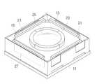
Translated fromKorean도 1은 본 발명의 일 실시예에 따른 VCM 액츄에이터의 결합된 상태를 도시한 사시도.1 is a perspective view showing a coupled state of the VCM actuator according to an embodiment of the present invention.
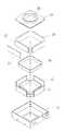
도 2는 도 1에 도시된 VCM 액츄에이터의 분해된 상태를 도시한 사시도.2 is a perspective view showing an exploded state of the VCM actuator shown in FIG.
도 3은 도 1에 도시된 VCM 액츄에이터의 내부 구성을 도시한 평면도.3 is a plan view showing the internal configuration of the VCM actuator shown in FIG.
도 4는 보빈의 구동에 의해 틸트가 발생한 상태를 도시한 사시도.4 is a perspective view showing a state in which the tilt is generated by the drive of the bobbin.
<도면 부호의 설명><Description of Drawing>
11: 홀더 13: 내부공간11: holder 13: inner space
15: 외측요크 17: 내측요크15: outer yoke 17: inner yoke
19: 코일 21: 구동 마그네트19: coil 21: drive magnet
23: 보빈 25: 렌즈23: bobbin 25: lens
27: 보정 마그네트27: calibration magnet
본 발명은 VCM 액츄에이터 및 그 틸트 보정방법에 관한 것이다.The present invention relates to a VCM actuator and its tilt correction method.
현재 모바일용 카메라 모듈은 고화소 및 고기능화 되어 가고 있으며, 일반 고사양의 디지털 카메라와 유사한 성능으로 급격히 기술개발이 진행되고 있다. 특히 오토 포커싱(auto focusing) 기술을 모바일용 크기에 구현하려는 시도가 다각도로 진행되고 있다. 이와 같이 정밀구동에 적용되는 구동기 또는 액츄에이터는 가장 일반적인 전기모터에서부터 압전소자를 이용한 것, 전자기 유도의 원리를 이용한 것에 까지 다양하다. 이 중 전자기 유도의 원리를 이용한 정밀 구동장치는 VCM(Voice Coil Motor)이라 일컬어지는 액츄에이터를 사용하는 것이 대표적이다.Currently, camera modules for mobile devices are becoming high pixels and high performance, and technology development is rapidly progressing with similar performance to general high-end digital cameras. In particular, attempts have been made to implement auto focusing technology in mobile-sized sizes. As such, the actuators or actuators applied to the precision driving may vary from the most common electric motors to those using piezoelectric elements and those using electromagnetic induction principles. Among them, the precision driving device using the principle of electromagnetic induction is typically using an actuator called a VCM (Voice Coil Motor).
이러한 VCM은 스피커의 진동원리를 구동기에 적용한 것으로서, 코일에 인가되는 전류의 극성에 따라 보빈이 왕복운동을 하는 것이다. 즉, VCM 액츄에이터는 마그네트에 의해 발생하는 자기장과 코일에 의해 생성되는 전기장의 상호 작용에 의해 발생하는 전자기적인 힘에 의해 렌즈를 구비한 보빈을 구동한다. 그러나, 종래의 VCM 액츄에이터는 마그네트의 표면 자속밀도의 차이 또는 마그네트와 코일 사이의 간격 차이 등과 같은 자기적 또는 기구적 불균형에 의해 보빈이 구동하면서 렌즈 틸트(tilt)가 발생하게 되는 문제점을 가진다. 이와 같은 틸트는 카메라 모듈과 같이 정밀성이 요구되는 장치에 있어서는, 장치의 작동 불량을 결정할 수 있는 중요한 요소가 된다.The VCM applies the vibration principle of the speaker to the driver, and the bobbin reciprocates according to the polarity of the current applied to the coil. That is, the VCM actuator drives the bobbin with a lens by electromagnetic force generated by the interaction of the magnetic field generated by the magnet and the electric field generated by the coil. However, the conventional VCM actuator has a problem in that lens tilt occurs while the bobbin is driven by magnetic or mechanical imbalance such as a difference in surface magnetic flux density of the magnet or a gap between the magnet and the coil. Such tilt is an important factor that can determine the malfunction of the device in a device requiring precision such as a camera module.
본 발명은 틸트를 보정할 수 있는 VCM 액츄에이터 및 그 틸트 보정방법에 관한 것이다.The present invention relates to a VCM actuator capable of correcting tilt and a tilt correction method thereof.
본 발명의 일 측면에 따른 VCM 액츄에이터는, 다각형의 내부공간을 구비한 홀더와, 내부공간에 다각형의 각 면에 대응하여 장착되는 구동 마그네트와, 내부공간에 장착되며 구동 마그네트에 인접하게 배치되는 코일과, 코일과 결합하며 중심에 렌즈를 구비하는 보빈과, 보빈의 구시 틸트가 발생하는 다각형의 적어도 일면에 대응하여 장착되는 보정 마그네트를 포함한다.According to an aspect of the present invention, a VCM actuator includes a holder having a polygonal inner space, a driving magnet mounted to correspond to each side of the polygon in the inner space, and a coil mounted in the inner space and disposed adjacent to the driving magnet. And a bobbin coupled to the coil and having a lens in the center, and a correction magnet mounted to correspond to at least one surface of the polygon in which the old tilt of the bobbin is generated.
본 발명의 실시예들은 다음과 같은 특징을 하나 또는 그 이상 구비할 수 있다. 예를 들면, 구동 마그네트는 사각 마그네트일 수 있고, 보정 마그네트는 구동 마그네트의 내측 또는 외측에 장착될 수 있다. 그리고 코일은 다각형 형상을 갖을 수 있다.Embodiments of the present invention may have one or more of the following features. For example, the driving magnet may be a square magnet, and the correction magnet may be mounted inside or outside the driving magnet. And the coil may have a polygonal shape.
또한, VCM 액츄에이터는 홀더의 내부에 장착되어 다각형 형상을 가지는 외측요크와, 외측요크와 일정 간격 이격되어 위치하며 외측요크에 대응하는 형상을 갖는 내측요크를 더 포함하며, 구동 마그네트, 보정 마그네트 및 코일은 외측요크와 내측요크 사이에 위치할 수 있다. 내측요크 및 외측요크는 일체로 형성될 수 있다.In addition, the VCM actuator further includes an outer yoke mounted inside the holder and having a polygonal shape, the inner yoke having a shape corresponding to the outer yoke, and spaced apart from the outer yoke at a predetermined interval, and including a driving magnet, a correction magnet, and a coil. May be located between the outer yoke and the inner yoke. The inner yoke and the outer yoke may be integrally formed.
그리고 내측요크 및 외측요크는 니켈 또는 니켈 합금으로 구성될 수 있다. 다각형은 사각형일 수 있다.The inner yoke and the outer yoke may be made of nickel or a nickel alloy. The polygon may be a rectangle.
본 발명의 일 측면에 따른 VCM 액츄에이터의 틸트 보정방법은, 코일에 전류를 인가하여 보빈을 구동하는 단계와, 보빈의 틸트량을 측정하는 단계와, 보빈의 구동시 틸트가 발생하는 부분에 대응하는 구동 마그네트에 인접하여 보정 마그네트를 장착하는 단계를 포함한다.Tilt correction method of the VCM actuator according to an aspect of the present invention, the step of driving the bobbin by applying a current to the coil, measuring the tilt amount of the bobbin, and corresponds to the portion where the tilt occurs when driving the bobbin Mounting a correction magnet adjacent the drive magnet.
본 발명의 실시예들은 다음과 같은 특징을 하나 또는 그 이상 구비할 수 있다. 예를 들면, 보정 마그네트를 장착하는 단계는 보빈의 틸트량의 범위에 따라 미리 크기가 정해진 보정 마그네트를 장착할 수 있다. 그리고 보정 마그네트는 구동 마그네트의 내측 또는 외측에 장착될 수 있다.Embodiments of the present invention may have one or more of the following features. For example, in the mounting of the correction magnet, the correction magnet may be mounted in a predetermined size according to the range of tilt amount of the bobbin. The correction magnet may be mounted inside or outside the driving magnet.
이하, 본 발명에 따른 VCM 액츄에이터 및 그 틸트 보정방법의 실시예를 첨부도면을 참조하여 상세히 설명하기로 하며, 첨부 도면을 참조하여 설명함에 있어, 동일하거나 대응하는 구성 요소는 동일한 도면번호를 부여하고 이에 대한 중복되는 설명은 생략하기로 한다.Hereinafter, an embodiment of the VCM actuator and its tilt correction method according to the present invention will be described in detail with reference to the accompanying drawings, in the description with reference to the accompanying drawings, the same or corresponding components are given the same reference numerals. Duplicate description thereof will be omitted.
도 1 및 도 2를 참조하면, 본 발명의 일 실시예에 따른 VCM 액츄에이터는, 다각형의 내부공간(13)을 구비한 홀더(11), 내부공간(13)의 다각형 각 면에 대응하여 장착되는 구동 마그네트(21), 내부공간(13)에 장착되며 구동 마그네트(21) 내에 위치하는 다각형의 코일(19), 코일(19)과 결합하며 중심에 렌즈(25)를 구비하는 보빈(23), 보빈(23)의 구동시 틸트가 발생하는 다각형의 적어도 일면에 대응하여 구동 마그네트(21)에 장착되는 보정 마그네트(27)를 포함한다. 그리고 구동 마그네트(21)에 의해 발생하는 자기력선을 코일(19)에 집중하게 하는 외측요크(15) 및 내측요크(17)를 포함한다.1 and 2, the VCM actuator according to an embodiment of the present invention, the
홀더(11)는 일정한 내부공간(13)을 가지며 상면이 개방된 직육면체 형상을 갖는다. 상기 홀더(11)의 내부공간(13)에는 외측요크(15), 내측요크(17), 코일(19), 구동 마그네트(21), 보정 마그네트(27) 및 보빈(23)이 수용된다. 도 1 내지 도 2에서는 홀더(11)를 직육면체로 도시하였지만, 본 발명은 이에 국한되는 것은 아니며, 홀더(11)는 육각형, 팔각형 등과 같은 다각형 형상을 구비할 수 있음은 물론이다. 이 경우, 홀더(11)의 내부공간(13)에 수용되는 외측요크(15), 내측요크(17), 코일(19), 구동 마그네트(21), 보정 마그네트(27) 및 보빈(23)의 형상도 이에 대응하는 다각형으로 구성 또는 배치된다.The
도 2 내지 도 3을 참조하면, 외측요크(15) 및 내측요크(17)는 홀더(11)의 내부공간(13)에 장착되며, 외측요크(15) 및 내측요크(17) 사이의 공간에는 코일(19), 구동 마그네트(21) 및 보정 마그네트(27)가 위치한다. 외측요크(15) 및 내측요크(17)는 구동 마그네트(21) 또는 보정 마그네트(27)에 의해 발생하는 자기장이 코일(19)로 집중되게 함으로써 자기 효율을 높이는 역할을 한다. 그리고 생산성의 향상을 위해, 외측요크(15) 및 내측요크(17)는 일체로 형성될 수 있다.2 to 3, the
외측요크(15)는 홀더(11)의 형상에 대응하여 다각형 형상으로 배열된다. 외측요크(15)의 내측면에는 구동 마그네트(21)가 부착된다. 내측요크(17)는 외측요크(15)와 일정 간격 이격되어 위치하며, 외측요크(15)의 형상에 대응하는 다각형으로 배열된다. 외측요크(15) 및 내측요크(17)는 자기투과율(magnetic permeability)이 우수한 철(Fe), 냉간압연강(SPCC), 니켈(Ni) 또는 니켈합금(Ni alloy) 등으로 형성할 수 있다.The
코일(19)은 구동 마그네트(21) 및 내측요크(17) 사이에 위치하며 보빈(23) 에 장착된다. 코일(19)은 PCB(미도시) 등을 통해 인가되는 전류에 의해 전기장을 생성한다. 코일(19)에는 구동 마그네트(21)에 의해 생성된 자기장이 투과하는데, 자기장과 전기장의 상호 작용에 의한 전자기적인 힘에 의해 코일(19) 및 이와 결합된 보빈(23)이 구동하게 된다.The
구동 마그네트(21)는 다각형 형상의 외측요크(15) 각각의 내면에 장착된다. 구동 마그네트(21)는 원형 마그네트 또는 사각 마그네트를 사용할 수 있다. 사각 마그네트의 경우에는 원형 마그네트에 비해 가격이 저렴할 뿐만 아니라 불량률도 낮고, 자기적 특성도 우수한 장점이 있다.The driving
도 2를 참조하면, 보빈(23)은 코일(19)과 결합하여, 코일(19)과 구동 마그네트(21)의 상호 작용또는 코일(19)과 보정 마그네트(27)의 상호 작용에 의해 발생하는 전자기적인 힘에 의해 구동한다. 보빈(23)의 중앙에는 렌즈(25)가 장착된다. 보빈(23)은 구동 마그네트(21) 각각의 자속밀도의 차이 또는 구동 마그네트(21)와 코일(19) 사이 간격의 불균일에 의해 구동시 한쪽이 기울어지는 틸트가 발생할 수 있다. 본 실시예에서는 이러한 틸트가 발생하는 부분에 대응하는 적어도 하나의 구동 마그네트(21)에 보정 마그네트(27)를 장착함으로써 보빈(23)의 틸트를 보정할 수 있다.Referring to FIG. 2, the
보빈(23)의 중앙에는 렌즈(25)가 장착된다. 렌즈(25)의 개수는 필요에 따라 하나 이상 장착될 수 있으며, 보빈(23)의 상하 운동에 의해 렌즈(25)의 초점이 조정된다. 보빈(23)의 상하 운동은 코일(19)에 인가하는 전류의 양을 조절함으로써 가능하다. 그리고 렌즈(25)가 보빈(23)의 틸트에 의해 기울어지는 경우에는, 위에 서 설명한 바와 같이, 구동 마그네트(21)의 외측 또는 내측에 보정 마그네트(27)를 장착하여 기울어진 부분의 전자기적인 힘을 증가시켜 틸트를 방지할 수 있다.The
도 2 내지 도 3을 참조하면, 보정 마그네트(27)는 구동 마그네트(21)의 외측 또는 내측에 고정되며, 구동 마그네트(21)와 함께 자기장을 생성하여 코일(19)에 의해 생성된 전기장과의 상호 작용에 의해 전자기적인 힘을 생성한다.2 to 3, the
외측요크(15)에 고정된 구동 마그네트(21)의 표면자속밀도의 차이 또는 구동 마그네트(21)와 코일(19) 사이의 간격의 불균일 등에 의해, 도 4에 도시된 바와 같이, 보빈(23)의 어느 한 방향으로 기울어지는 틸트가 발생할 수 있다. 이러한 보빈(23)의 틸트는 렌즈(25)의 광축을 기울어지게 하여 카메라 모듈 전체의 불량을 유발한다. 따라서, 보빈(23)의 구동시 기울어진 부분에 해당하는 다각형(도 4에서는 사각형)의 적어도 일면에 보정 마그네트(27)를 장착하여, 틸트가 발생한 부분에서의 전자기적인 힘을 상승시켜 틸트를 보정할 수 있다.As shown in FIG. 4, the
보빈(23)의 틸트를 보정하는 방법은, 코일(19)에 전류를 인가하여 보빈(23)을 구동시키면서 보빈(23)의 구동시 틸트가 발생하는 지를 검사한다. 보빈(23)의 틸트를 검사하는 방법은 레이저를 이용한 오토 콜리메이터(auto collimator) 를 사용하여 틸트의 발생을 검사할 수 있다. 그리고 틸트가 발생한 부분에 대응하는 구동 마그네트(21)의 다각형 부분에 보정 마그네트(27)를 장착하여 틸트를 보정할 수 있다. 보정 마그네트(27)의 크기는 틸트가 발생한 정도에 따라 달라질 수 있다. 그리고 틸트의 발생 범위에 따라 미리 그 크기가 정해진 보정 마그네트(27)가 장착될 수 있다. 예를 들면, 보빈(23)의 틸트가 30˚~40˚, 40˚~50˚, 50˚~60˚인 범위로 나누고, 보빈(23)의 틸트가 각각의 범위에 해당할 경우 그 범위 내에서 틸트를 보정할 수 있는 다양한 크기를 갖는 보정 마그네트(27)를 미리 준비한다. 그리고 보빈(23)의 틸트가 발생한 부분에 대응하는 구동 마그네트(21)의 다각형 부분에 보정 마그네트(27)를 부착함으로써 틸트를 용이하게 보정할 수 있다.In the method of correcting the tilt of the
이와 같이 본 발명에 따른 VCM 액츄에이터의 틸트 보정방법은, 보빈(23)의 틸트 정도에 따라 구동 마그네트(21)에 보정 마그네트(27)를 부착하기만 하면 되기 때문에 공정이 간단하고 생산성을 향상시킬 수 있다.As described above, the tilt correction method of the VCM actuator according to the present invention is simple because the
이상에서 본 발명의 실시예를 설명하였지만, 본 발명의 다양한 변경예와 수정예도 본 발명의 기술적 사상을 구현하는 한 본 발명의 범위에 속하는 것으로 해석되어야 한다.Although the embodiments of the present invention have been described above, various changes and modifications of the present invention should also be construed as falling within the scope of the present invention as long as the technical idea of the present invention is realized.
본 발명은 틸트를 보정할 수 있는 VCM 액츄에이터 및 그 틸트 보정방법을 제공할 수 있다.The present invention can provide a VCM actuator capable of correcting the tilt and a method of correcting the tilt.
Claims (11)
Translated fromKoreanPriority Applications (1)
| Application Number | Priority Date | Filing Date | Title |
|---|---|---|---|
| KR1020050104951AKR100723917B1 (en) | 2005-11-03 | 2005-11-03 | BCMC Actuator and its Tilt Compensation Method |
Applications Claiming Priority (1)
| Application Number | Priority Date | Filing Date | Title |
|---|---|---|---|
| KR1020050104951AKR100723917B1 (en) | 2005-11-03 | 2005-11-03 | BCMC Actuator and its Tilt Compensation Method |
Publications (2)
| Publication Number | Publication Date |
|---|---|
| KR20070047992A KR20070047992A (en) | 2007-05-08 |
| KR100723917B1true KR100723917B1 (en) | 2007-05-31 |
Family
ID=38272644
Family Applications (1)
| Application Number | Title | Priority Date | Filing Date |
|---|---|---|---|
| KR1020050104951AExpired - Fee RelatedKR100723917B1 (en) | 2005-11-03 | 2005-11-03 | BCMC Actuator and its Tilt Compensation Method |
Country Status (1)
| Country | Link |
|---|---|
| KR (1) | KR100723917B1 (en) |
Families Citing this family (6)
| Publication number | Priority date | Publication date | Assignee | Title |
|---|---|---|---|---|
| KR101230095B1 (en)* | 2009-10-12 | 2013-02-05 | 엘지이노텍 주식회사 | Voice coil motor |
| KR101721263B1 (en)* | 2010-09-08 | 2017-04-10 | 엘지이노텍 주식회사 | Voice coil motor |
| KR102232029B1 (en)* | 2014-03-17 | 2021-03-26 | 엘지이노텍 주식회사 | Lens moving unit and camera module having the same |
| KR102376814B1 (en)* | 2014-03-17 | 2022-03-21 | 엘지이노텍 주식회사 | Lens moving unit and camera module having the same |
| WO2019045439A1 (en) | 2017-08-30 | 2019-03-07 | 엘지이노텍(주) | Lens driving device, and camera module and optical device including same |
| KR102510574B1 (en)* | 2021-03-19 | 2023-03-16 | 엘지이노텍 주식회사 | Lens moving unit and camera module having the same |
Citations (3)
| Publication number | Priority date | Publication date | Assignee | Title |
|---|---|---|---|---|
| JPH0829668A (en)* | 1994-07-18 | 1996-02-02 | Olympus Optical Co Ltd | Optical element moving device |
| JP2003050343A (en) | 2002-07-26 | 2003-02-21 | Olympus Optical Co Ltd | Optical element driving device |
| KR200370322Y1 (en) | 2004-10-01 | 2004-12-10 | 김용필 | Actuator For Auto Focusing In Camera |
- 2005
- 2005-11-03KRKR1020050104951Apatent/KR100723917B1/ennot_activeExpired - Fee Related
Patent Citations (3)
| Publication number | Priority date | Publication date | Assignee | Title |
|---|---|---|---|---|
| JPH0829668A (en)* | 1994-07-18 | 1996-02-02 | Olympus Optical Co Ltd | Optical element moving device |
| JP2003050343A (en) | 2002-07-26 | 2003-02-21 | Olympus Optical Co Ltd | Optical element driving device |
| KR200370322Y1 (en) | 2004-10-01 | 2004-12-10 | 김용필 | Actuator For Auto Focusing In Camera |
Also Published As
| Publication number | Publication date |
|---|---|
| KR20070047992A (en) | 2007-05-08 |
Similar Documents
| Publication | Publication Date | Title |
|---|---|---|
| KR102370739B1 (en) | Lens Drive Device, Camera Module, and Terminal with Camera | |
| TWI457693B (en) | Optical image stabilizer | |
| US7675566B2 (en) | Camera module | |
| TWI435110B (en) | Suspension mechanism for optical image anti-shake device | |
| US8531789B2 (en) | Leaf spring with high thrust | |
| US9179048B2 (en) | Camera module | |
| US8503119B2 (en) | Leaf spring with high vickers hardness | |
| JP5417127B2 (en) | Lens drive device | |
| TWI525360B (en) | Lens drive | |
| US20120002102A1 (en) | Camera module | |
| WO2011068085A1 (en) | Lens driving device | |
| WO2007026830A1 (en) | Lens drive device | |
| KR20110096487A (en) | Lens drive | |
| JP2011090064A (en) | Lens driving device, autofocus camera and cellular phone with camera | |
| JP2010091894A (en) | Driving device and lens driving device | |
| KR100723917B1 (en) | BCMC Actuator and its Tilt Compensation Method | |
| JP2025123553A (en) | Lens drive unit and lens barrel equipped with same | |
| JP2011112709A (en) | Lens drive device, autofocus camera, and cellular phone having built-in camera | |
| JP2011053600A (en) | Lens driving device | |
| KR102560792B1 (en) | Lens moving unit and camera module having the same | |
| KR101082757B1 (en) | Voice coil motor | |
| KR100620790B1 (en) | Camera auto focus | |
| JP6827226B1 (en) | Lens drive unit and lens barrel equipped with this | |
| JP6432045B2 (en) | Actuator and lens barrel provided with actuator | |
| KR20150109894A (en) | Camera actuator for portable device |
Legal Events
| Date | Code | Title | Description |
|---|---|---|---|
| A201 | Request for examination | ||
| PA0109 | Patent application | St.27 status event code:A-0-1-A10-A12-nap-PA0109 | |
| PA0201 | Request for examination | St.27 status event code:A-1-2-D10-D11-exm-PA0201 | |
| D13-X000 | Search requested | St.27 status event code:A-1-2-D10-D13-srh-X000 | |
| D14-X000 | Search report completed | St.27 status event code:A-1-2-D10-D14-srh-X000 | |
| E902 | Notification of reason for refusal | ||
| PE0902 | Notice of grounds for rejection | St.27 status event code:A-1-2-D10-D21-exm-PE0902 | |
| P11-X000 | Amendment of application requested | St.27 status event code:A-2-2-P10-P11-nap-X000 | |
| P13-X000 | Application amended | St.27 status event code:A-2-2-P10-P13-nap-X000 | |
| R18-X000 | Changes to party contact information recorded | St.27 status event code:A-3-3-R10-R18-oth-X000 | |
| PG1501 | Laying open of application | St.27 status event code:A-1-1-Q10-Q12-nap-PG1501 | |
| E701 | Decision to grant or registration of patent right | ||
| PE0701 | Decision of registration | St.27 status event code:A-1-2-D10-D22-exm-PE0701 | |
| GRNT | Written decision to grant | ||
| PR0701 | Registration of establishment | St.27 status event code:A-2-4-F10-F11-exm-PR0701 | |
| PR1002 | Payment of registration fee | St.27 status event code:A-2-2-U10-U11-oth-PR1002 Fee payment year number:1 | |
| PG1601 | Publication of registration | St.27 status event code:A-4-4-Q10-Q13-nap-PG1601 | |
| LAPS | Lapse due to unpaid annual fee | ||
| PC1903 | Unpaid annual fee | St.27 status event code:A-4-4-U10-U13-oth-PC1903 Not in force date:20100526 Payment event data comment text:Termination Category : DEFAULT_OF_REGISTRATION_FEE | |
| PC1903 | Unpaid annual fee | St.27 status event code:N-4-6-H10-H13-oth-PC1903 Ip right cessation event data comment text:Termination Category : DEFAULT_OF_REGISTRATION_FEE Not in force date:20100526 | |
| R18-X000 | Changes to party contact information recorded | St.27 status event code:A-5-5-R10-R18-oth-X000 | |
| P22-X000 | Classification modified | St.27 status event code:A-4-4-P10-P22-nap-X000 | |
| R18-X000 | Changes to party contact information recorded | St.27 status event code:A-5-5-R10-R18-oth-X000 |